IEC Medical electrical equipment Part 1: General requirements for basic safety and essential performance
|
|
|
- Piers Stevens
- 5 years ago
- Views:
Transcription
1 12 Test Report issued under the responsibility of: Medical electrical equipment art 1: General requirements for basic safety and essential performance Report Reference No... : T /17 Date of issue... : Total number of pages... : 226 pages CB Testing Laboratory... : SIQ Testing and Certification GmbH Address... : Angerstarße 11, D Buchloe, Germany Applicant s name... : GlobTek, Inc. Address... : 186 Veterans Drive, Northvale, NJ 07647, USA Test specification: Standard... : :2005 (Third Edition) + CORR. 1: CORR. 2: A1:2012 (or : 2012 reprint) Test procedure... : CB Scheme Non-standard test method..: Test Report Form No... : IEC60601_1K Test Report Form Originator... : UL(US) Master TRF... : Copyright 2015 Worldwide System for Conformity Testing and Certification of Electrotechnical Equipment and Components (IECEE), Geneva, Switzerland. All rights reserved. This publication may be reproduced in whole or in part for non-commercial purposes as long as the IECEE is acknowledged as copyright owner and source of the material. IECEE takes no responsibility for and will not assume liability for damages resulting from the reader's interpretation of the reproduced material due to its placement and context. If this Test Report Form is used by non-iecee members, the IECEE/IEC logo and the reference to the CB Scheme procedure shall be removed. This report is not valid as a CB Test Report unless signed by an approved CB Testing Laboratory and appended to a CB Test Certificate issued by an NCB in accordance with IECEE 02. General disclaimer: The test results presented in this report relate only to the object tested. This report shall not be reproduced, except in full, without the written approval of the Issuing CB testing laboratory. The authenticity of this Test Report and its contents can be verified by contacting the NCB, responsible for this Test Report.
2 age 2 of 226 Report No. T /17 Test item description... : Direct lug-in or Open frame ower Supply Trade Mark... : GlobTek, Inc. Manufacturer... : GlobTek, Inc. 186 Veterans Drive, Northvale, NJ 07647, USA Model/Type reference... : GT (M or -) (- or CC) WWVV-X.XA-FW Family where: M or for marked identification and not related to safety 41060: Series code (- or CC): - = Constant Voltage Model, CC = Constant Current Model WW: is the rated output wattage designation, with a maximum value of "25" VV: is the standard rated output voltage designation, with a maximum value of "30" - X.X: Denotes the optional deviation, subtracted or added from standard output voltage in 0,1 volt increments or blank to indicate the no voltage different. A is optional for marked identification and not related to safety. - FW: is optional and means open frame power supply Models providing MO protection are additionally marked with 2MO near model name. Ratings... : I/: V~; Hz; 0,6 A; Class II O/: 5-30 V dc; Max. 3,0 A; Max. 25 W See table below. Direct plug-in ower supply: Model name Output voltage Max. output current Max. output power GTM41060(- or CC)-1505A 5,0 V dc 3,0 A 15 W GTM41060(- or CC)-1706-X.XA 5,1-6 V dc 3,0 A 18 W GTM41060(- or CC)-1807-X.XA 6,1-7 V dc 2,95 A 18 W GTM41060(- or CC)-1809-X.XA 7,1-9 V dc 2,54 A 18 W GTM41060(- or CC)-2512-X.XA 9,1-12 V dc 2,75 A 25 W GTM41060(- or CC)-2515-X.XA 12,1-15 V dc 2,07 A 25 W GTM41060(- or CC)-2518-X.XA 15,1-18 V dc 1,66 A 25 W GTM41060(- or CC)-2520-X.XA 18,1-20 V dc 1,38 A 25 W GTM41060(- or CC)-2524-X.XA 20,1-24 V dc 1,24 A 25 W GTM41060(- or CC)-2530-X.XA 24,1-30 V dc 1,04 A 25 W
3 age 3 of 226 Report No. T /17 Open-frame ower supply: Model name Output voltage Max. output current Max. output power GTM41060(- or CC)-1505A-FW 5,0 V dc 3,0 A 15 W GTM41060(- or CC)-1706-X.XA-FW 5,1-6 V dc 3,0 A 18 W GTM41060(- or CC)-1807-X.XA-FW 6,1-7 V dc 2,95 A 18 W GTM41060(- or CC)-1809-X.XA-FW 7,1-9 V dc 2,54 A 18 W GTM41060(- or CC)-2512-X.XA-FW 9,1-12 V dc 2,75 A 25 W GTM41060(- or CC)-2515-X.XA-FW 12,1-15 V dc 2,07 A 25 W GTM41060(- or CC)-2518-X.XA-FW 15,1-18 V dc 1,66 A 25 W GTM41060(- or CC)-2520-X.XA-FW 18,1-20 V dc 1,38 A 25 W GTM41060(- or CC)-2524-X.XA-FW 20,1-24 V dc 1,24 A 25 W GTM41060(- or CC)-2530-X.XA-FW 24,1-30 V dc 1,04 A 25 W
4 - ~ age 4 of226 Report No. T /17 Testing procedure and testing location: ~ CB Testing Laboratory: SIQ Testing and Certification GmbH Testing location/ address... : Angerstarl1e 11, D Buchloe, Germany D Associated CB Testing Laboratory: Testing location/ address : Tested by (name, function, signature)... : Alexander Mayr Approved by (name, function, signature).. : Bostjan Glavic D Testing procedure: CTF Stage 1: Testing location/ address : ~~ ~~-~ I Tested by (name, function, signature)... : Approved by (name, function, signature)... : D Testing procedure: CTF Stage 2: Testing location/ address... : Tested by (name, function, signature)... : Witnessed by (name, function, signature). : Approved by (name, function, signature)... : D Testing procedure: CTF Stage 3: D Testing procedure: CTF Stage 4: Testing location/ address... : Tested by (name, function, signature)..... : Witnessed by (name, function, signature).: Approved by (name, function, signature)... : Supervised by (name, function, signature): TRF No. IEC60601_1 K
5 age 5 of 226 Report No. T /17 List of Attachments (including a total number of pages in each attachment): 1. Test Report (165 pages) 2. National Differences to : AM1: 2012 Enclosure No. 1 (10 pages) 3. hoto documentation Enclosure No. 2 (16 pages) 4. Schematics, layouts and transformer drawings Enclosure No. 3 (35 pages) Summary of testing Tests performed (name of test and test clause): 4.11 ower Input 5.7 Humidity treatment Legibility of marking Durability of marking c) Working Voltage / ower Measurement ME equipment intended to be connected to a power source by a plug Working voltage Measurement Touch Current Dielectric Strength test of solid insulation materials with safety functions Measurement of creepage distances and air clearances 11.1 Excessive temperatures in ME EQUIMENT 13.2 Single Fault conditions ush test Impact test Drop test Mould-stress relief test Transformer short circuit Transformer overload Evaluation of voltage limiting components in SELV circuits Summary of compliance with National Differences List of countries addressed: Testing location: Initial report up to report Rev. No. 3.0 SIQ Ljubljana, Tržaška c. 2, SI-1000, Ljubljana, Slovenia Report Rev. No. 4.0 SIQ Testing and Certification GmbH, Angerstarße 11, D Buchloe, Germany Austria**, Canada*, France*, Slovenia*, Sweden**, Switzerland*, Turkey*, United Kingdom**, USA* as listed in online CB-Bulletin. * National differences according to : 2005 declared. ** EU group differences The product fulfils the requirements of EN : A1: A11:2011+ A12:2014


 Marking plate for models provided MOO protection (example")
6 age 6 of 226 Report No. T /17 Copy of marking plate The artwork below may be only a draft. The use of certification marks on a product must be authorized by the respective NCBs that own these marks. a) Marking plate for models provided MOO protection (example only): b) Marking plate for models provided MO protection (example only): Serial number label:

7 age 7 of 226 Report No. T /17 ackaging label
8 age 8 of 226 Report No. T /17 GENERAL INFORMATION Test item particulars (see also Clause 6): Classification of installation and use... : ortable (direct plug-in power supply) and power supply for building in (open frame power supply) Device type (component/sub-assembly/ equipment/ system) : Component level power supply (Direct plug-in power supply and open frame power supply for building in) Intended use (Including type of patient, application location) : ower supply is intended to provide power to medical devices with isolation grade MOO (Means of Operator rotection) or MO (Means of atient rotection) for models additionally marked with 2MO. Mode of operation... : Continuous Supply connection... Direct plug-in power supply: mains plug part of the power supply Open frame power supply: for connection to the mains by means of internal mains wirings (end product consideration) Accessories and detachable parts included... : No accessories and detachable parts included Other options include... : No other options included Testing Date of receipt of test item(s)... : Rev.No.: 4.0 Dates tests performed... : From to From to Rev.No.: 4.0 ossible test case verdicts: - test case does not apply to the test object... : - test object does meet the requirement... : ass () - test object was not evaluated for the requirement... : N/E (collateral standards only) - test object does not meet the requirement... : Fail (F) Abbreviations used in the report: - normal condition... : N.C. - single fault condition... : S.F.C. - means of Operator protection... : MOO - means of atient protection... : MO
9 age 9 of 226 Report No. T /17 General remarks: Before starting to use the TRF please read carefully the 4 instructions pages at the end of the report on how to complete the new version J of TRF for IEC for rd edition with Amendment 1. "(See Attachment #)" refers to additional information appended to the report. "(See appended table)" refers to a table appended to the report. The tests results presented in this report relate only to the object tested. This report shall not be reproduced except in full without the written approval of the testing laboratory. List of test equipment must be kept on file and available for review. Additional test data and/or information provided in the attachments to this report. Throughout this report a comma / point is used as the decimal separator. Manufacturer s Declaration per sub-clause of IECEE 02:2012 The application for obtaining a CB Test Certificate includes more than one factory location and a declaration from the Manufacturer stating that the sample(s) submitted for evaluation is (are) representative of the products from each factory has been provided... : Yes Not applicable When differences exist; they shall be identified in the General product information section. Name and address of factory (ies)...: 1) GlobTek, Inc. 186 Veterans Drive, Northvale, NJ 07647, USA 2) GlobTek (Suzhou) Co., Ltd. Building 4, No. 76, Jinling East Road, Suzhou Industrial ark, Jiangsu CN , China General product information: EUT is a protection class II direct plug-in power supply unit or open frame power supply unit intended for supplying end medical product by its output voltage or current. In respect to supply connection the unit is marked with the Model/Type reference number as direct plug-in or open frame. 2 x MOO (2 x Means of Operator rotection) isolation is provided between primary and secondary side of the power supply. Secondary output circuit is separated from mains by reinforced insulation and rated SELV non hazardous energy levels. For models additionally marked with 2MO near model name: 2 x MO (2 x Means of atient rotection) isolation is provided between primary and secondary side of the power supply. Secondary output circuit is separated from mains by reinforced insulation and rated SELV non hazardous energy levels. Model Differences: Differences within the GTM41060 family are limited to minor component changes to determine specific output voltage and current parameters. However change is related to the two different classifications of the use due design. Both models with last two letters of model name (-FW) are for built in use (open frame) and therefore are to be installed within the end product enclosure. End product evaluation is necessary for open frame power supplies.
10 age 10 of 226 Report No. T /17 Explanation of the test program: 1. The risk management requirements of the standard according to ISO were addressed. 2. Medical power supply does not provide any clinical function and has therefore no essential performance. 3. The MEE is not intended to be used in an oxygen rich environment and not to be used in conjunction with flammable anaesthetics. 4. The unit provides internally two fuses in line and neutral 5. The unit is a direct plug-in equipment. 6. ower supply was evaluated for Means of Operator rotection (MOO): - 2 x MOO between primary and secondary circuit - 2 x MOO between primary and external plastic enclosure surface (applicable for direct plug-in power supply) ower supply was evaluated for Means of atient rotection (MO) (for models additionally marked with 2MO near model name): - 2 x MO between primary and secondary circuit - 2 x MO between primary and external plastic enclosure surface (applicable for direct plug-in power supply). 7. Secondary output circuit is separated from mains by reinforced insulation and rated SELV. The output does not provide hazard energy level. 8. ower supply is provided only with technical specification. 9. ower supply is rated as class II (provided in fully plastic enclosure) construction. Open-frame power supply complies with Class II construction (end product consideration). 10. The transformer T1 provides reinforced insulation. This transformer is built up to fulfil the requirement of insulation class B (130 C). See also list of safety critical components. 11. The equipment has been evaluated for use in a ollution Degree 2 and overvoltage category II environment and a maximum altitude of 3000 m. 12. ower supply is provided with plastic enclosure made by non-flammable material UL94 V-1. See also list of safety critical components. Open-frame power supply is provided without external enclosure. Electrical / Fire enclosure shall be considered during end medical product approval. 13. The product was evaluated for a maximum ambient of 40 C. The temperature test was performed 100 mm above bench without forced air cooling 14. Cleaning/disinfection tests shall be considered within end product investigation.
11 age 11 of 226 Report No. T /17 History Sheet Date Report Number Change Revision No T /09 Initial Test Report issued T /13 Revision of the report. Corrected typing errors. No changes that influence on safety T /13 Modified nomenclature. After review, no additional tests were considered necessary T /14 Manufacturer added alternative models to comply with MO requirements (change of layouts, change of transformer construction (increase width of margin tapes), 2 x Y1 capacitors in series provided between primary and secondary circuit). No other changes on the product. Additional evaluation of Risk Management File complying with ISO was performed. Risk Management File provided by the manufacturer. After review, the following tests were considered necessary: - Working voltage measurements - Evaluation of creepage/clearance distances - Leakage current measurements - Dielectric strength test Update of list of critical components. See first page. See first page. Standard was upgraded to IEC :2005 (Third Edition) + A1:2012 No modification of the products. The following tests were performed: - RMF review Leakage current measurements List of critical components updated All additional tests marked with Rev. No. in order to fulfil traceability requirements
12 age 12 of 226 Report No. T /17 INSULATION DIAGRAM
13 age 13 of 226 Report No. T /17 TABLE: INSULATION DIAGRAM ollution degree... : D2 Overvoltage category... : OVC II Altitude... : Up to 3000 meters Additional details on parts considered as applied parts... : Area Number and type of Means of rotection: MOO, MO CTI Working voltage Required creepage (mm) Vrms None Areas (See Clause 4.6 for details) Required clearance (mm) ower supply unit evaluated for Means of Operator rotection (MOO) (Single Y1 capacitor provided between primary and secondary circuit) A 1 x MOO IIIb ,5 2,3 Vpk (2,0* 1,14) Measured creepage (mm) B -- IIIb Verified via short-circuiting. See abnormal testing. C1 2 x MOO IIIb ,0 4,6 (4,0 * 1,14) D1a 2 x MOO IIIb ,4 5,1 (4,4 * 1,14) D1b 2 x MOO IIIb ,4 5,1 Supplementary Information: (4,4 * 1,14) Both enclosure parts are fixed together by means of ultrasonic welding. Measured clearance (mm) Remarks 3,0 3,0 Before primary fuses. Minimum distance between primary component (Fuse F1) to inner enclosure: 1,2 mm 8,7 5,7 Measured between primary components and accessible enclosure 7,0 7,0 Measured on the transformer. 7,8 7,8 Measured on CB
 (Models additionally marked with 2MO")
14 age 14 of 226 Report No. T /17 ower supply unit evaluated for Means of atient rotection (MO) (Models additionally marked with 2MO near model name) (2 x Y1 capacitors in series provided between primary and secondary circuit)
15 age 15 of 226 Report No. T /17 A 1 x MOO IIIb ,5 2,3 (2,0 * 1,14) B -- IIIb Verified via short-circuiting. See abnormal testing. 3,0 3,0 Before primary fuses. C1 2 x MO IIIb ,0 5,0 8,7 5,7 Measured between primary components and accessible enclosure D1a 2 x MO IIIb ,4 7,0 10,0 10,0 Measured on the transformer. D1b 2 x MO IIIb ,4 7,0 9,0 9,0 Measured on CB below transformer D1c 2 x MO IIIb ,0 5,0 9,4 5,3 Measured on CB below transformer (in 2 to pin 6) D 2 x MO IIIb ,0 5,0 8,5 5,0 Between CY1 primary side to CY2 secondary side D2a 1 x MO IIIb ,0 2,5 5,5 2,5 Between CY1 secondary side to secondary D2b 1 x MO IIIb ,0 2,5 4,3 3,8 Between CY1 secondary side to primary D2c 1 x MO IIIb ,0 2,5 4,2 3,8 Between CY2 primary side to primary D2d 1 x MO IIIb ,0 2,5 5,5 2,5 Between CY2 primary side to secondary Supplementary information: Transformer core is considered as floating. Margin tape 5,0 mm provided on both sides of primary and secondary wires. 3 layers of insulation tape provided between primary and secondary windings. Both enclosure parts are fixed together by means of ultrasonic welding. Minimum distance between primary component (Fuse F1) to inner enclosure: 1,2 mm
16 age 16 of 226 Report No. T /17
17 age 17 of 226 Report No. T /17 INSULATION DIAGRAM CONVENTIONS and GUIDANCE: A measured value must be provided in the value columns for the device under evaluation. The symbol > (greater than sign) must not be used. Switch-mode power supplies must be re-evaluated in the device under evaluation therefore must not be used with a generic statement that the component is certified. Insulation diagram is a graphical representation of equipment insulation barriers, protective impedance and protective earthing. If feasible, use the following conventions to generate the diagram: - All isolation barriers are identified by letters between separate parts of diagram, for example separate transformer windings, optocouplers, wire insulation, creepage and clearance distances. - arts connected to earth with large dots are protectively earthed. Other connections to earth are functional - Applied parts are extended beyond the equipment enclosure and terminated with an arrow. - arts accessible to the operator only are extended outside of the enclosure, but are not terminated with an arrow.
18 age 18 of 226 Report No. T /17 4 GENERAL REQUIREMENTS 4.1 Requirements of this standard applied in NORMAL USE and reasonably foreseeable misuse RISK MANAGEMENT ROCESS FOR ME EQUIMENT OR ME SYSTEMS General requirement for RISK MANAGEMENT - ROCESS complies with ISO14971 (2007)... : See Appended RM Results Table Evaluating RISK a) Compliance with the standard reduces residual risk to an acceptable level b) Manufacturer has defined risk acceptability criteria in the RISK MANAGEMENT LAN... : c) When no specific technical requirements provided manufacturer has determined HAZARDS or HAZARDOUS SITUATIONS exists. - HAZARDS or HAZARDOUS SITUATIONS have been evaluated using the RISK MANAGEMENT ROCESS MANUFACTURER has addressed HAZARDS or HAZARDOUS SITUATIONS not specifically addressed in the series. 4.3 erformance of clinical functions necessary to achieve intended USE or that could affect the safety of the ME EQUIMENT or ME SYSTEM were identified during RISK ANALYSIS. - erformance limits were identified in both NORMAL CONDITION and SINGLE FAULT CONDITION. - Loss or degradation of performance beyond the limits specified by the MANUFACTURER were evaluated - Functions with unacceptable risks are identified as ESSENTIAL ERFORMANCE... : -- RISK MANAGEMENT LAN Document: GT-RMLAN ower supply unit is not end medical product. ower supply unit is not end medical product. - RISK CONTROL measures implemented - Methods used to verify the effectiveness of RISK CONTROL measures implemented 4.4 EXECTED SERVICE LIFE stated in RISK MANAGEMENT FILE... : The expected service life is specified by the manufacturer: 10 years. 4.5 Alternative RISK CONTROL methods utilized: No equivalent safety used.
19 age 19 of 226 Report No. T /17 RESIDUAL RISK resulting from the alternative RISK CONTROL measures or tests is acceptable and comparable to RESIDUAL RISK resulting from application of this standard... : (ISO Cl , 5, ) Alternative means based scientific data or clinical opinion or comparative studies... : 4.6 RISK MANAGEMENT ROCESS identifies parts that can come into contact with ATIENT but not defined as ALIED ARTS, subjected to the requirements for ALIED ARTS, except for Clause : MANUFACTURER assesses the risk of accessible parts coming into contact with the patient... : (ISO Cl , 5, ) Assessment identified the ALIED ART TYE requirements... : 4.7 ME EQUIMENT remained SINGLE FAULT SAFE, or the RISK remained acceptable as determined by Clause : MANUFACTURER RISK ANALYSIS was used to determine failures to be tested... : (ISO Cl ) Failure of any one component at a time that could result in a HAZARDOUS SITUATION, including those in 13.1, simulated physically or theoretically... : 4.8 All components and wiring whose failure could result in a HAZARDOUS SITUATION used according to their applicable ratings, unless specified... : Components and wiring exception in the standard or by RISK MANAGEMENT ROCESS RISK MANAGEMENT ROCESS assesses components to identify components where the failure results in a HAZARDOUS SITUATION for components used outside their ratings... : (ISO Cl , 5, ) MANUFACTURER identified components where the failure results in a HAZARDOUS SITUATION... : Components determined to be acceptable where used as a MEANS OF ROTECTION... : No equivalent safety used. No RM considered necessary See Appended Insulation Diagram Table and RM Results Table 4.6 No such parts. No such parts. No RM considered necessary Short circuit or open circuit of relevant single components performed. See Table 13.2: Single fault conditions in accordance with to , inclusive. RISK ANALYSIS reference: EL5 (ISO Cl ) See appended Table 13.2 for simulated physical test. All components are suitable and used within their rating. See appended table All components are suitable and used within their ratings. No RM considered necessary. All components are suitable and used within their ratings. All components are suitable and used within their ratings.
20 age 20 of 226 Report No. T /17 Reliability of components used as MEANS OF ROTECTION assessed for conditions of use in ME EQUIMENT, and they complied with one of the following -- a) Applicable safety requirements of a relevant IEC or ISO standard b) Requirements of this standard applied in the absence of a relevant IEC or ISO standard 4.9 A COMONENT WITH HIGH-INTEGRITY CHARACTERISTICS provided and selected appropriately... : RISK MANAGEMENT FILE includes an assessment to determine if the failure of components results in unacceptable RISK... : (ISO Cl , 5, ) Components identified and required to be COMONENTS WITH HIGH INTEGRITY CHARACTERISTIC: Approved critical components used. Considered. No such components provided. No RM considered necessary ower supply ME EQUIMENT is suitable for connection to indicated power source (select applicable)... : Maximum rated voltage for ME EQUIMENT intended to be connected to SULY MAINS: Supply mains V for HAND-HELD ME EQUIMENT (V)... : Not hand-held MEE. 250 V d.c. or single-phase a.c., or 500 V polyphase a.c. for ME EQUIMENT and ME SYSTEMS with a RATED input 4 kva (V)... : 500 V for all other ME EQUIMENT and ME SYSTEMS Vac 4.11 ower input Steady-state measured input of ME EQUIMENT or ME SYSTEM at RATED voltage or voltage range and at operating settings indicated in instructions for use didn t exceed marked rating by more than 10%... : See appended Table GENERAL REQUIREMENTS FOR TESTING ME EQUIMENT 5.1 Test not performed when analysis indicated condition being tested was adequately evaluated by other tests or methods... : --
21 age 21 of 226 Report No. T /17 RISK MANAGEMENT FILE identifies combinations of simultaneous independent faults that could result in a HAZARDOUS SITUATION. (ISO Cl ) 5.3 Tests conducted within the environmental conditions specified in technical description Type test performed according to all applicable clauses of standard : A1:2012. No RM considered necessary. -- Temperature (ºC), Relative Humidity (%)... : Temperature: 0-40 C Relative humidity: 0 to 90% RH Specified within technical specifications. Atmospheric ressure (ka)... : 70 to a) Supply voltage during tests was the least favourable of the voltages specified in or voltages marked on ME EQUIMENT (V)... : b) ME EQUIMENT marked with a RATED frequency range tested at the least favourable frequency within the range (Hz)... : c) ME EQUIMENT with more than one RATED voltage, both a.c./ d.c. or both external power and INTERNAL ELECTRICAL OWER SOURCE tested in conditions (see 5.4) related to the least favourable voltage, nature of supply, and type of current... : d) ME EQUIMENT intended for only d.c. supply connection tested with d.c. and influence of polarity considered... : e)me EQUIMENT tested with alternative ACCESSORIES and components specified in ACCOMANYING DOCUMENTS to result in the least favourable conditions... : f) ME EQUIMENT connected to a separate power supply as specified in instructions for use 5.7 ME EQUIMENT or parts thereof affected by climatic conditions were set up completely, or partially, with covers detached and subjected to a humidity preconditioning prior to tests of Clauses and : ME EQUIMENT heated to a temperature between T and T + 4 C for at least 4 h and placed in a humidity chamber and ambient within 2 C of T in range of +20 C to +32 C for indicated time Vac 50-60Hz Rated supply voltage: V ac AC supply voltage only. No accessories provided. Mains operated equipment. Complete MEE was subjected to humidity preconditioning treatment. T = 26 C Time 48H Humidity: 94,5% 5.9 Determination of ALIED ARTS and ACCESSIBLE ARTS
22 age 22 of 226 Report No. T / ALIED ARTS identified by inspection and reference to ACCOMANYING DOCUMENTS... : No ALIED ARTS provided ACCESSIBLE ARTS Accessibility determined using standard test finger of Fig Test hook of Fig. 7 inserted in all openings of ME EQUIMENT and pulled with a force of 20 N for 10 s Conductive parts of actuating mechanisms of electrical controls accessible after removal of handles, knobs, levers and the like regarded as ACCESSIBLE ARTS... : Conductive parts of actuating mechanisms not considered ACCESSIBLE ARTS when removal of handles, knobs, required use of a TOOL... : See Appended Table See Appended Table Direct plug-in version provided with plastic enclosure without openings. End product consideration for open frame version. No actuating mechanism. No actuating mechanism. 6 CLASSIFICATION OF ME EQUIMENT AND ME SYSTEMS 6.2 CLASS I ME EQUIMENT, externally powered Not Class I equipment. CLASS II ME EQUIMENT, externally powered INTERNALLY OWERED ME EQUIMENT No protective earth provided. Class II: Direct plug-in version Class II construction: Open frame version EUT is not internally powered equipment. Mains operated equipment. EQUIMENT with means of connection to a SULY MAINS complied with CLASS I or CLASS II ME EQUIMENT requirements when so connected, and when not connected to SULY MAINS with INTERNALLY OWERED ME EQUIMENT requirements TYE B ALIED ART Not applied parts provided. TYE BF ALIED ART TYE CF ALIED ART DEFIBRILLATION-ROOF ALIED ARTS 6.3 ENCLOSURES classified according to degree of protection against ingress of water and particulate matter as per IEC : I40 (relevant for direct plug-in power supply).
23 age 23 of 226 Report No. T / ME EQUIMENT or its parts intended to be sterilized classified according to method(s) of sterilization in instructions for use... : 6.5 ME EQUIMENT and ME SYSTEMS intended for use in an OXYGEN RICH ENVIRONMENT classified for such use and complied with No parts intended to be sterilized. Unit is not intended to be used in an oxygen rich environment. 6.6 CONTINUOUS or Non-CONTINUOUS OERATION... : Unit is intended for continuous operation. 7 ME EQUIMENT IDENTIFICATION, MARKING, AND DOCUMENTS Legibility of Markings Test for Markings specified in Clause : Required markings can be removed only with a TOOL or by appreciable force, are durable and remain CLEARLY LEGIBLE during EXECTED SERVICE LIFE of ME EQUIMENT in NORMAL USE See Appended Table See appended Tables Marking on the outside of ME EQUIMENT or ME EQUIMENT parts At least markings in 7.2.2, 7.2.5, 7.2.6, , and were applied when size of EQUIMENT, its part, an ACCESSORY, or ENCLOSURE did not permit application of all required markings... : Remaining markings fully recorded in ACCOMANYING DOCUMENTS... : Markings applied to individual packaging when impractical to apply to ME EQUIMENT Single use item marked... : All required markings provided on the marking plate. All necessary information are provided on the marking plate. MEE is not intended for single use ME EQUIMENT marked with: -- the name or trademark and contact information of the MANUFACTURER -- a MODEL OR TYE REFERENCE See attached copy of Marking late a serial number or lot or batch identifier; and -- the date of manufacture or use by date -- Detachable components of the ME EQUIMENT not marked; misidentification does not present an unacceptable risk, or RISK MANAGEMENT FILE includes an assessment of the RISKS relating to misidentification of all detachable parts... : (ISO Cl , 5, 6.4) No detachable components provided. No detachable components provided. No RM considered necessary.
24 age 24 of 226 Report No. T /17 Detachable components of the ME EQUIMENT are marked with the name or trademark of the MANUFACTURER, and a MODEL OR TYE REFERENCE Software forming part of a EMS identified with a unique identifier... : Symbol 11 on Table D.1 used, optionally, advice to OERATOR to consult ACCOMANYING DOCUMENTS Safety sign 10 on Table D.2) used, advising OERATOR that ACCOMANYING DOCUMENTS must be consulted ACCESSORIES marked with name or trademark and contact information of their MANUFACTURER, and... : No EMS. Not required for power supply. No accessories provided. - with a MODEL or TYE REFERENCE a serial number or lot or batch identifier the date of manufacture or use by date Markings applied to individual packaging when not practical to apply to ACCESSORIES ME EQUIMENT and ME SYSTEM intended to receive power from other equipment, provided with one of the following - the name or trademark of the manufacturer of the other electrical equipment and type reference marked adjacent to the relevant connection point; or Table D.2, safety sign No. 10 adjacent to the relevant connection point and listing of the required details in the instructions for use; or Special connector style used that is not commonly available on the market and listing of the required details in the instructions for use. MEE is not intended to receive power from other equipment. Mains operated equipment Connection to the Supply Mains Marking appearing on the outside of part containing SULY MAINS connection and, adjacent to connection point For ERMANENTLY INSTALLED ME EQUIMENT, NOMINAL supply voltage or range marked inside or outside of ME EQUIMENT RATED supply voltage(s) or RATED voltage range(s) with a hyphen (-) between minimum and maximum voltages (V, V-V)... : Marking plate provided on the outer side of the plastic enclosure. Not permanently installed equipment V~
25 age 25 of 226 Report No. T /17 Multiple RATED supply voltages or multiple RATED supply voltage ranges are separated by (V/V)... : -- Nature of supply and type of current... : The following symbol provided near supply voltage range: ~ on the marking plate. Symbols 1-5, Table D.1 (used for same parameters... : RATED supply frequency or RATED frequency range in hertz... : Symbol 9 of Table D.1 used for CLASS II ME EQUIMENT... : Symbol No. 1 provided near supply voltage range on the marking plate. Supply frequency expressed in Hz. Symbol No. 9 provided on the marking plate RATED input in amps or volt-amps, (A, VA)... : Rated input expressed in Amperes. RATED input in amps or volt-amps, or in watts when power factor exceeds 0.9 (A, VA, W)... : RATED input for one or more RATED voltage ranges provided for upper and lower limits of the range or ranges when the range(s) is/are greater than ± 10 % of the mean value of specified range (A, VA,W)... : Input at mean value of range marked when range limits do not differ by more than 10 % from mean value (A, VA, W)... : Marking includes long-time and most relevant momentary volt-ampere ratings when provided, each plainly identified and indicated in ACCOMANYING DOCUMENTS (VA)... : Marked input of ME EQUIMENT provided with means for connection of supply conductors of other electrical equipment includes RATED and marked output of such means (A, VA, W)... : Rated input expressed in Amperes. Not relevant for power supply Output connectors Output connectors are marked, except for MULTILE SOCKET-OUTLETS or connectors intended for specified ACCESSORIES or equipment Rating of the output provided on the marking plate. Rated Voltage (V), Rated Current (A)... : Rated output voltage and current provided on the marking plate. Rated ower (W), Output Frequency (Hz)... : DC output ME EQUIMENT or its parts marked with the I environmental Code per IEC according to classification in 6.3 (Table D.3, Code 2), marking optional for ME EQUIMENT or parts rated IX0... : I40 No protection against ingress of water provided (relevant for direct plug-in power supply).
26 age 26 of 226 Report No. T / Degrees of protection against electric shock as classified in 6.2 for all ALIED ARTS marked with relevant symbols... : TYE B ALIED ARTS with symbol 19 of Table D.1 TYE BF ALIED ARTS with symbol 20 of Table D.1... : TYE CF ALIED ARTS with symbol 21 of Table D.1... : DEFIBRILLATION-ROOF ALIED ARTS marked with symbols of Table D.1... : roper symbol marked adjacent to or on connector for ALIED ART... : Safety sign 2 of Table D.2 placed near relevant outlet... : An explanation indicating protection of ME EQUIMENT against effects of discharge of a cardiac defibrillator depends on use of proper cables included in instructions for use... : No ALIED ARTS in power supply ME EQUIMENT suitable for CONTINUOUS OERATION Equipment is intended for continuous operation; therefore no marking is required. DUTY CYCLE for ME EQUIMENT intended for non- CONTINUOUS OERATION appropriately marked to provide maximum on and off time... : Type and full rating of a fuse marked adjacent to ACCESSIBLE fuse-holder No fuse-holder provided. Fuse type... : -- Voltage (V) and Current (A) rating... : -- Operating speed (s) and Breaking capacity... : hysiological effects safety sign and warning statements... : Nature of HAZARD and precautions for avoiding or minimizing the associated RISK described in instructions for use... : (ISO Cl , 5, 6.3) HIGH VOLTAGE TERMINAL DEVICES on the outside of ME EQUIMENT accessible without the use of a TOOL marked with symbol 24 of Table D.1 Equipment does not produce physiological effects. MEE does not produce physiological effects. No RM considered necessary. No such voltage provided within power supply unit Requirements for cooling provisions marked.. : No cooling provided ackaging marked with special handling instructions for transport and/or storage... : No special handling requirements.
27 age 27 of 226 Report No. T /17 ermissible environmental conditions marked on outside of packaging... : ackaging marked with a suitable safety sign indicating premature unpacking of ME EQUIMENT could result in an unacceptable RISK... : RISK MANAGEMENT FILE includes the assessment to determine premature unpacking of ME EQUIMENT or its parts could result in an unacceptable RISK.... : (ISO Cl , 5, ) ackaging of sterile ME EQUIMENT or ACCESSORIES marked sterile and indicates the methods of sterilization RATED maximum supply pressure from an external source marked on ME EQUIMENT adjacent to each input connector, and... : ackage is marked with environmental conditions. No risk of premature unpacking. No RM considered necessary. No pressure used. - the RATED flow rate also marked Symbol 7 of Table D.1 marked on FUNCTIONAL EARTH TERMINAL... : Removable protective means marked to indicate the necessity for replacement when the function is no longer needed... : MOBILE ME EQUIMENT marked with its mass including its SAFE WORKING LOAD in kilograms... : No functional earth provided. 7.3 Marking on the inside of ME EQUIMENT or ME EQUIMENT parts Maximum power loading of heating elements or lamp-holders designed for use with heating lamps marked near or in the heater (W)... : A marking referring to ACCOMANYING DOCUMENTS provided for heating elements or lamp-holders designed for heating lamps that can be changed only by SERVICE ERSONNEL using a TOOL Symbol 24 of Table D.1, or safety sign No.3 of Table D.2 used to mark presence of HIGH VOLTAGE parts... : No heating elements provided. No HIGH VOLTAGE parts within the equipment Type of battery and mode of insertion marked : No battery provided. An identifying marking provided referring to instructions in ACCOMANYING DOCUMENTS for batteries intended to be changed only by SERVICE ERSONNEL using a TOOL... : A warning provided indicating replacement of lithium batteries or fuel cells when incorrect replacement would result in an unacceptable RISK... :
28 age 28 of 226 Report No. T /17 RISK MANAGEMENT FILE includes an assessment to determine the replacement of lithium batteries or fuel cells leads to an unacceptable RISK if replaced incorrectly... : (ISO Cl , 5, 6.3) ACCOMANYING DOCUMENTS contain a warning indicating the replacement of lithium batteries or fuel cells by inadequately trained personnel could result in a HAZARD... : Fuses, replaceable THERMAL CUT-OUTS and OVER- CURRENT RELEASES, accessible by use of a TOOL Identified... : Neither batteries nor battery compartments incorporated. No RM considered necessary. No batteries provided. No such fuses provided. Internal fuses marked as follows: F1: T1A/250VAC F2: T1A/250VAC Those fuses not intended to be replaced by the operator. Voltage (V) and Current (A) rating... : -- Operating speed(s), size & breaking capacity. : ROTECTIVE EARTH TERMINAL marked with symbol 6 of Table D.1 Markings on or adjacent to ROTECTIVE EARTH TERMINALS not applied to parts requiring removal to make the connection, and remained visible after connection made Symbol 7 of Table D.1 marked on FUNCTIONAL EARTH TERMINALS Terminals for supply conductors marked adjacent to terminals... : Terminals for supply connections are not marked, the RISK MANAGEMENT FILE includes an assessment of the RISKS resulting from misconnections... : (ISO Cl. 4.3) Terminal markings included in ACCOMANYING DOCUMENTS when ME EQUIMENT too small to accommodate markings Terminals exclusively for neutral supply conductor in ERMANENTLY INSTALLED ME EQUIMENT marked with Code 1 of Table D.3 Marking for connection to a 3-phase supply, complies with IEC No protective earth terminal provided. No functional earthing is provided. EUT is direct plug-in or open frame power supply unit intended for supplying medical product by its output voltage. No terminals for supply conductors provided. No terminals for supply conductors provided. No RM considered necessary.
29 age 29 of 226 Report No. T /17 Markings on or adjacent to electrical connection points not applied to parts requiring removal to make connection, and remained visible after connection made For supply connections, use wiring materials suitable for at least X C or equivalent, marked at the point of supply connections Statement not applied to parts requiring removal to make the connection, and CLEARLY LEGIBLE after connections made 7.4 Marking of controls and instruments The on & off positions of switch to control power to ME EQUIMENT or its parts, including mains switch, marked with symbols 12 and 13 of Table D.1 or No mains switch provided. indicated by an adjacent indicator light, or Green indicator light provided to indicate ower ON. indicated by other unambiguous means The on/off positions of push button switch with bi-stable positions marked with symbol 14 of Table D.1, and No push buttons provided. status indicated by adjacent indicator light status indicated by other unambiguous means The on/off positions of push button switch with momentary on position marked with symbol 15 of Table D.1 or status indicated by adjacent indicator light status indicated by other unambiguous means Different positions of control devices/switches indicated by figures, letters, or other visual means RISK MANAGEMENT FILE identifies controls where a change in setting during NORMAL USE results in an unacceptable RISK... : (ISO Cl , 5, 6.2, 6.3) Controls provided with an associated indicating device when change of setting of a control could result in an unacceptable RISK to ATIENT in NORMAL USE... : or an indication of direction in which magnitude of the function changes No control devices provided. No controls and instruments provided. No RM considered necessary.
30 age 30 of 226 Report No. T /17 Control device or switch that brings the ME EQUIMENT into the "stand-by" condition marked with symbol IEC Numeric indications of parameters on ME EQUIMENT expressed in SI units according to ISO except the base quantities listed in Table 1 expressed in the indicated units ISO applied for application of SI units, their multiples, and certain other units All Markings in Sub-clause 7.4 complied with tests and criteria of and : 7.5 Safety signs Safety sign with established meaning used No such safety sign provided. RISK MANAGEMENT ROCESS identifies markings used to convey a warning, prohibition or mandatory action that mitigate a RISK not obvious to the OERATOR... : (ISO Cl , 5, 6.3) Affirmative statement together with safety sign placed in instructions for use if insufficient space on ME EQUIMENT Specified colours in ISO used for safety signs... : Safety notices include appropriate precautions or instructions on how to reduce RISK(S) Safety signs including any supplementary text or symbols described in instructions for use - and in a language acceptable to the intended OERATOR No such markings provided. No RM considered necessary. 7.6 Symbols Meanings of symbols used for marking described in instructions for use... : Symbols used for controls and performance conform to the IEC or ISO publication where symbols are defined, as applicable Explanation provided within specifications. 7.7 Colours of the insulation of conductors ROTECTIVE EARTH CONDUCTOR identified by green and yellow insulation Insulation on conductors inside ME EQUIMENT forming ROTECTIVE EARTH CONNECTIONS identified by green and yellow at least at terminations Green and yellow insulation identify only following conductors: Class II MEE.
31 age 31 of 226 Report No. T /17 ROTECTIVE EARTH CONDUCTORS conductors specified in OTENTIAL EQUALIZATION CONDUCTORS FUNCTIONAL EARTH CONDUCTORS Neutral conductors of OWER SULY CORDS are light blue Colours of conductors in OWER SULY CORDS in accordance with IEC or IEC Indicator lights and controls Red indicator lights used only for Warning No red indicator light provided. Yellow indicator lights used only for Caution No yellow indicator light provided. Green indicator lights used only for Ready for use Other colours: Meaning other than red, yellow, or green (colour, meaning)... : Green indicator light indicate ower ON No other colours used Red used only for emergency control 7.9 ACCOMANYING DOCUMENTS ME EQUIMENT accompanied by documents containing instructions for use, and a technical description ACCOMANYING DOCUMENTS identify ME EQUIMENT by the following, as applicable: Name or trade-name of MANUFACTURER and contact information for the RESONSIBLE ORGANIZATION can be referred to... : ower supply unit is not end medical product. Shall be evaluated during end medical product approval. Only technical specifications provided by the manufacturer. Manufacturer name and address and contact information provided within Instruction for use. MODEL or TYE REFERENCE... : Model name provided within technical specifications provided by the manufacturer. When ACCOMANYING DOCUMENTS provided electronically, USABILITY ENGINEERING ROCESS includes instructions as to what is required in hard copy or as markings on ME EQUIMENT ACCOMANYING DOCUMENTS specify special skills, training, and knowledge required of OERATOR or RESONSIBLE ORGANIZATION and environmental restrictions on locations of use Technical specifications provided in hard copy. ower supply unit is not end medical product. End product consideration.
32 age 32 of 226 Report No. T /17 ACCOMANYING DOCUMENTS written at a level consistent with education, training, and other needs of individuals for whom they are intended Only technical specifications provided by the manufacturer (English version) Instructions for use include the required information use of ME EQUIMENT as intended by the MANUFACTURER: -- frequently used functions, known contraindication(s) to use of ME EQUIMENT - parts of the ME EQUIMENT that are not serviced or maintained while in use with the patient name or trademark and address of the MANUFACTURER ower supply unit is part of the investigation. No such parts. rovided within specifications. MODEL OR TYE REFERENCE rovided within specifications. Instruction for use included the following when the ATIENT is an intended OERATOR: End product consideration. ower supply unit is not end medical product. the ATIENT is an intended OERATOR warning against servicing and maintenance while the ME EQUIMENT is in use - functions the ATIENT can safely use and, where applicable, which functions the ATIENT cannot safely use; and maintenance the ATIENT can perform Classifications as in Clause 6, all markings per Clause 7.2, and explanation of safety signs and symbols marked on ME EQUIMENT Instructions for use are in a language acceptable to the intended operator Instructions for use include all warning and safety notices Warning statement for CLASS I ME EQUIMENT included Warnings regarding significant RISKS of reciprocal interference posed by ME EQUIMENT during specific investigations or treatments Information on potential electromagnetic or other interference and advice on how to avoid or minimize such interference Warning statement for ME EQUIMENT supplied with an integral MULTILE SOCKET-OUTLET provided rovided within specifications. English version provided and evaluated. Not Class I equipment, no protective earth provided. ower supply unit is not end medical product. ower supply unit is not end medical product. Not supplied from an integral multiple socket-outlet.
33 age 33 of 226 Report No. T /17 The RESONSIBLE ORGANIZATION is referred to this standard for the requirements applicable to ME SYSTEMS Statement on ME EQUIMENT for connection to a separate power supply provided in instructions Warning statement for mains- operated ME EQUIMENT with additional power source not automatically maintained in a fully usable condition indicating the necessity for periodic checking or replacement of power source RISK MANAGEMENT FILE assesses the RISK resulting from leakage of batteries... : (ISO Cl , 5, 6.3) Where the RISK is unacceptable, the IFU includes a warning to remove the battery if the ME EQUIMENT is not likely to be used for some time... : Specifications of replaceable INTERNAL ELECTRICAL OWER SOURCE when provided... : Warning indicating ME EQUIMENT must be connected to an appropriate power source when loss of power source would result in an unacceptable RISK... : Instructions for use include a description of ME EQUIMENT, its functions, significant physical and performance characteristics together with the expected positions of OERATOR, ATIENT, or other persons near ME EQUIMENT in NORMAL USE Information provided on materials and ingredients ATIENT or OERATOR is exposed to Restrictions specified on other equipment or NETWORK/DATA COULINGS, other than those forming part of an ME SYSTEM, to which a SIGNAL INUT/OUTUT ART may be connected Mains operated equipment. No additional power source incorporated. Neither batteries nor battery compartments incorporated. Loss of power does not result in an unacceptable risk. No RM considered necessary. No batteries provided. No internal replaceable power source provided. ower supply unit is not end medical product; shall be considered during end medical product approval. Not relevant for power supply unit. ALIED ARTS specified No applied parts provided Information provided indicating where the installation instructions may be found or information on qualified personnel who can perform the installation Instructions provided indicating not to position ME EQUIMENT to make it difficult to operate the disconnection device Mains plug is considered as disconnecting device (relevant for direct plug-in version). End product consideration for open frame version.
34 age 34 of 226 Report No. T / Necessary information provided for OERATOR to bring ME EQUIMENT into operation Not relevant for power supply unit. End medical product consideration Information provided to operate ME EQUIMENT Not relevant for power supply unit. Meanings of figures, symbols, warning statements, abbreviations and indicator lights described in instructions for use A list of all system messages, error messages, and fault messages provided with an explanation of messages including important causes and possible action(s) to be taken to resolve the problem indicated by the message Information provided for the OERATOR to safely terminate operation of ME EQUIMENT Information provided on cleaning, disinfection, and sterilization methods, and applicable parameters that can be tolerated by ME EQUIMENT parts or ACCESSORIES specified Components, ACCESSORIES or ME EQUIMENT marked for single use, except when required by MANUFACTURER to be cleaned, disinfected, or sterilized prior to use Instructions provided on preventive inspection, calibration, maintenance and its frequency Information provided for safe performance of routine maintenance necessary to ensure continued safe use of ME EQUIMENT arts requiring preventive inspection and maintenance to be performed by SERVICE ERSONNEL identified including periods of application Instructions provided to ensure adequate maintenance of ME EQUIMENT containing rechargeable batteries to be maintained by anyone other than SERVICE ERSONNEL A list of ACCESSORIES, detachable parts, and materials for use with ME EQUIMENT provided Other equipment providing power to ME SYSTEM sufficiently described End medical product consideration. Green indicator light provided on top side of the enclosure to indicate power ON. ower supply unit is not end medical product. End product consideration. No sterile parts. ower supply unit is not end medical product. End product consideration. No such parts specified within technical specifications.
35 age 35 of 226 Report No. T / Disposal of waste products, residues, etc., and of ME EQUIMENT and ACCESSORIES at the end of their EXECTED SERVICE LIFE are identified in the instruction for use... : Instructions for use include information specified in or identify where it can be found (e.g. in a service manual) Instruction for use for ME EQUIMENT emitting radiation for medical purposes, indicate the nature, type, intensity and distribution of this radiation The instructions for use for ME EQUIMENT or ACCESSORIES supplied sterile indicate that they have been sterilized and the method of sterilization The instructions for use indicate the necessary instructions in the event of damage to the sterile packaging, and where appropriate, details of the appropriate methods of resterilization The instructions for use contain a unique version identifier... : rovided within technical specifications. Not relevant for power supply unit. End product consideration. Equipment does not emit radiation for medical purposes. No parts supplied sterile. Version QA /11/15/ Technical description All essential data provided for safe operation, transport, storage, and measures or conditions necessary for installing ME EQUIMENT, and preparing it for use rovided within technical specifications provided by the manufacturer. Technical description separable from instructions for use contains required information, as follows all applicable classifications in Clause 6, warning and safety notices, and explanation of safety signs marked on ME EQUIMENT a brief description of the ME EQUIMENT, how the ME EQUIMENT functions and its significant physical and performance characteristics; and a unique version identifier... : -- MANUFACTURER S optional requirements for minimum qualifications of SERVICE ERSONNEL documented in technical description The technical description contains the following required information type and full rating of fuses used in SULY MAINS external to ERMANENTLY INSTALLED ME EQUIMENT... : a statement for ME EQUIMENT with a non- DETACHABLE OWER SULY CORD if OWER SULY CORD is replaceable by SERVICE ERSONNEL, and Not permanently installed. MEE does not provide a nondetachable power supply cord.
36 age 36 of 226 Report No. T /17 instructions for correct replacement of interchangeable or detachable parts specified by MANUFACTURER as replaceable by SERVICE ERSONNEL, and No such parts. RISK MANAGEMENT FILE includes an assessment to determine if replacement of components results in any unacceptable RISKS... : (ISO Cl , 5, ) warnings identifying nature of HAZARD when replacement of a component could result in an unacceptable RISK, and when replaceable by SERVICE ERSONNEL all information necessary to safely replace the component Technical description indicates, MANUFACTURER will provide circuit diagrams, component part lists, descriptions, calibration instructions to assist to SERVICE ERSONNEL in parts repair Means used to comply with requirements of clearly identified in technical description No replaceable components specified by the manufacturer. No RM considered necessary. The following provided within technical specifications: Globtek Inc. will not be liable for the safety and performance of these power supplies if unauthorized access and repair occurs. End user should consult applicable UL, CSA or EN standards for proper installation instructions. Mains plug is considered as disconnection device. End product consideration for open frame version. 8 ROTECTION AGAINST ELECTRICAL HAZARDS FROM ME EQUIMENT 8.1 Limits specified in Clause 8.4 not exceeded for ACCESSIBLE ARTS and ALIED ARTS in NORMAL or SINGLE FAULT CONDITIONS RISK MANAGEMENT FILE identifies conductors and connectors where breaking free results in a HAZARDOUS SITUATION... : (ISO Cl. 4.3) -- RMF Reference to specific RISKS: EL6 (ISO Cl. 4.3) 8.2 Requirements related to power sources Connection to a separate power source When ME EQUIMENT specified for connection to a separate power source other than SULY MAINS, separate power source considered as part of ME EQUIMENT or combination considered as an ME SYSTEM Tests performed with ME EQUIMENT connected to separate power supply when one specified When a generic separate power supply specified, specification in ACCOMANYING DOCUMENTS examined Mains operated equipment.
37 age 37 of 226 Report No. T / Connection to an external d.c. power source No HAZARDOUS SITUATION as described in 13.1 developed when a connection with wrong polarity made for ME EQUIMENT from an external d.c. source ME EQUIMENT connected with correct polarity maintained BASIC SAFETY and ESSENTIAL ERFORMANCE rotective devices that can be reset by anyone without a TOOL returns to NORMAL CONDITION on reset Mains operated equipment. 8.3 Classification of ALIED ARTS a) ALIED ART specified in ACCOMANYING DOCUMENTS as suitable for DIRECT CARDIAC ALICATION is TYE CF b) An ALIED ART provided with a ATIENT CONNECTION intended to deliver electrical energy or an electrophysiological signal to or from ATIENT is TYE BF or CF ALIED ART c) An ALIED ART not covered by a) or b) is a TYE B, BF, or CF No ALIED ARTS provided 8.4 Limitation of voltage, current or energy ACCESSIBLE ARTS and ALIED ARTS a) Currents from, to, or between ATIENT CONNECTIONS did not exceed limits for ATIENT LEAKAGE CURRENT & ATIENT AUXILIARY CURRENT : b) LEAKAGE CURRENTS from, to, or between ACCESSIBLE ARTS did not exceed limits for TOUCH CURRENT... : c) Limits specified in b) not applied to parts when probability of a connection to a ATIENT, directly or through body of OERATOR, is negligible in NORMAL USE, and the OERATOR is appropriately instructed Voltage to earth or to other ACCESSIBLE ARTS did not exceed 42.4 V peak a.c. or 60 V d.c. for above parts in NORMAL or single fault condition (V a.c. or d.c.)... : Energy did not exceed 240 VA for longer than 60 s or stored energy available did not exceed 20 J at a potential of 2 V or more (VA or J)... : d) Voltage and energy limits specified in c) above also applied to the following: No ALIED ARTS provided. See appended Table 8.7 Touch leakage current measured on output and plastic enclosure (metal foil used). -- No such output connectors provided.
38 age 38 of 226 Report No. T /17 internal parts touchable by test pin in Fig 8 inserted through an opening in an ENCLOSURE; and internal parts touchable by a metal test rod with a diameter of 4 mm and a length 100 mm, inserted through any opening on top of ENCLOSURE or through any opening provided for adjustment of pre-set controls by RESONSIBLE ORGANIZATION in NORMAL USE using a TOOL Test pin or the test rod inserted through relevant openings with minimal force of no more than 1 N Test rod inserted in every possible position through openings provided for adjustment of pre-set controls that can be adjusted in NORMAL USE, with a force of 10 N Test repeated with a TOOL specified in instructions for use Test rod freely and vertically suspended through openings on top of ENCLOSURE e) Devices used to de-energize parts when an ACCESS COVER opened without a TOOL gives access to parts at voltages above levels permitted by this Clause comply with for mains isolating switches and remain effective in SINGLE FAULT CONDITION A TOOL is required when it is possible to prevent the devices from operating Worst case voltage between pins of plug and between either supply pin and ENCLOSURE did not exceed 60 V one sec after disconnecting the plug of ME EQUIMENT or its parts (V)... : When voltage exceeded 60 V, calculated or measured stored charge didn t exceed 45 μc.. : Residual voltage of conductive parts of capacitive circuits, having become accessible after ME EQUIMENT was de-energized after removal of ACCESS COVERS, didn t exceed 60V or calculated stored charge didn t exceed 45μC... : A device manually discharging capacitors used when automatic discharging was not possible and ACCESS COVERS could be removed only with aid of a TOOL No parts accessible by test pin (plastic enclosure without openings provided). End product consideration for open frame power supply unit. No parts accessible by test pin (plastic enclosure without openings provided). End product consideration for open frame power supply unit. See appended Table The measured voltage did not exceed 60 V. No removable parts.
39 age 39 of 226 Report No. T /17 Capacitor(s) and connected circuitry marked with symbol 24 of Table D.1, and manual discharging device specified in technical description... : 8.5 Separation of parts MEANS OF ROTECTION (MO) Two MEANS of ROTECTION provided for ME EQUIMENT to prevent ALIED and other ACCESSIBLE ARTS from exceeding limits in Varnishing, enamelling, oxidation, and similar protective finishes and coatings with sealing compounds re-plasticizing at temperatures expected during operation and sterilization disregarded as MEANS OF ROTECTION No such protection provided. Components and wiring forming a MEANS OF ROTECTION comply with MEANS OF ATIENT ROTECTION (MO) ower supply unit evaluated for Means of atient protection (MO) (for models additionally marked with 2MO near model name). Solid insulation forming a MEANS OF ATIENT ROTECTION complied with dielectric strength test... : CREEAGE and CLEARANCES forming a MEANS OF ATIENT ROTECTION complied with Table ROTECTIVE EARTH CONNECTIONS forming a MEANS OF ATIENT ROTECTION complied with Cl. 8.6 No protective earth provided. Y1 or Y2 capacitor complying with standard IEC considered one MEANS OF ATIENT ROTECTION... : Single Y1 capacitor used for two MEANS OF ATIENT ROTECTION when the working voltage is less than 42,4 V peak a.c. or 60 V d.c.... : Two capacitors used in series, each RATED for total WORKING VOLTAGE across the pair and have the same NOMINAL capacitance See appended Tables and Y1 capacitors (CY1, CY2) in series provided between primary and secondary circuit. CY1=CY2=1,0 nf Both rated: 250 Vac
40 age 40 of 226 Report No. T /17 Voltage Total Working (V) and C Nominal (µf)... : GTM : GTM : GTM : MEANS OF OERATOR ROTECTION (MOO) ower supply unit evaluated for Means of Operator protection (MOO). Solid insulation forming a MEANS OF OERATOR ROTECTION complied with: -- dielectric strength test... : -- requirements of IEC for INSULATION CO-ORDINATION CREEAGE and CLEARANCES forming a MEANS OF OERATOR ROTECTION complied with: -- limits of Tables 13 to 16 (inclusive); or -- requirements of IEC for INSULATION CO-ORDINATION ROTECTIVE EARTH CONNECTIONS forming a MEANS OF OERATOR ROTECTION complied with Cl. 8.6 or with requirements and tests of IEC for protective earthing... : No protective earth provided.
41 age 41 of 226 Report No. T /17 A Y2 (IEC ) capacitor is considered one MEANS OF OERATOR ROTECTION... : A Y1 (IEC ) capacitor is considered two MEANS OF OERATOR ROTECTION... : Two capacitors used in series each RATED for total WORKING VOLTAGE across the pair and have the same NOMINAL capacitance Single Y1 capacitor provided between primary and secondary circuit. Single capacitor provided. Voltage Total Working (V) and C Nominal (µf)... : -- oints and applied parts at which impedances of components, CREEAGE, CLEARANCES, ROTECTIVE EARTH CONNECTIONS or insulation, prevent ACCESSIBLE ARTS from exceeding limits in 8.4 were examined whether a failure at any of these points is to be regarded as a NORMAL or SINGLE FAULT CONDITION A MEANS OF ROTECTION protecting ALIED ARTS, or parts identified by 4.6 as parts subject to the same requirements, considered MEANS OF ATIENT ROTECTION... : A MEANS OF ROTECTION protecting other parts considered MEANS OF OERATOR ROTECTION... : Separation of ATIENT CONNECTIONS ATIENT CONNECTIONS of F-TYE ALIED ART separated from all other parts by equivalent to one MEANS OF ATIENT ROTECTION for a WORKING VOLTAGE equal to the MAX. MAINS VOLTAGE... : Separation requirement not applied between multiple functions of a single F-TYE ALIED ART ATIENT CONNECTIONS treated as one ALIED ART in the absence of electrical separation between ATIENT CONNECTIONS of same or another function MANUFACTURER has defined if multiple functions are to be considered as all within one ALIED ART or as multiple ALIED ARTS...: Classification as TYE BF, CF, or DEFIBRILLATION- ROOF applied to one entire ALIED ART LEAKAGE CURRENT tests conducted per : -- Dielectric strength test conducted per : -- CREEAGE and CLEARANCES measured... : -- A protective device connected between ATIENT CONNECTIONS of an F-TYE ALIED ART and ENCLOSURE to protect against excessive voltages did not operate below 500 V r.m.s No patient connections provided. No applied parts provided.
42 age 42 of 226 Report No. T / ATIENT CONNECTIONS of a TYE B ALIED ART not ROTECTIVELY EARTHED are separated by one MEANS OF ATIENT ROTECTION from metal ACCESSIBLE ARTS not ROTECTIVELY EARTHED... : No TYE B ALIED ART provided. except when metal ACCESSIBLE ART is physically close to ALIED ART and can be regarded as a part of ALIED ART; and RISK that metal ACCESSIBLE ART will make contact with a source of voltage or LEAKAGE CURRENT above permitted limits is acceptably low LEAKAGE CURRENT tests conducted per : -- Dielectric strength test conducted per : -- Relevant CREEAGE and CLEARANCES measured -- RISK MANAGEMENT FILE includes an assessment of the RISK of metal ACCESSIBLE ARTS contacting a source of voltage or LEAKAGE CURRENT above the limits... : (ISO Cl , 5) No TYE B ALIED ART provided. No RM considered necessary A connector on a ATIENT lead or ATIENT cable located at the end of the lead or cable remote from ATIENT, with conductive part not separated from all ATIENT CONNECTIONS by one MEANS OF ATIENT ROTECTION for a WORKING VOLTAGE equal to MAXIMUM MAINS VOLTAGE - cannot be connected to earth or hazardous voltage while the ATIENT CONNECTIONS are in contact with ATIENT... : conductive part of connector not separated from all ATIENT CONNECTIONS did not come into contact with a flat conductive plate of not less than 100 mm diameter CLEARANCE between connector pins and a flat surface is at least 0.5 mm conductive part pluggable into a mains socket protected from making contact with parts at MAINS VOLTAGE by insulation with a CREEAGE DISTANCE of at least 1.0 mm, a 1500 V dielectric strength and complying with required test finger did not make electrical contact with conductive part when applied against access openings with a force of 10 N, Test finger test (10 N)... : -- Except when RISK MANAGEMENT ROCESS includes an assessment of RISKS resulting from contact with objects other than mains sockets or flat surfaces... : (ISO Cl , 5) No applied parts provided, no patient leads provided. Non-metal connector used for connection of applied part. No RM considered necessary.
43 age 43 of 226 Report No. T / WORKING VOLTAGE -- Input supply voltage to ME EQUIMENT was RATED voltage or voltage within RATED range resulting in highest measured value (V)... : WORKING VOLTAGE for d.c. voltages with superimposed ripple was average value when peak-to-peak ripple less than 10% of average value or peak voltage when peak-to-peak ripple exceeding 10% of average value (V)... : WORKING VOLTAGE for each MEANS OF ROTECTION forming DOUBLE INSULATION was voltage DOUBLE INSULATION, as a whole, subjected to (V)... : Intentional or accidental earthing of ATIENT regarded as a NORMAL CONDITION for WORKING VOLTAGE involving a ATIENT CONNECTION not connected to earth WORKING VOLTAGE between ATIENT CONNECTIONS of an F-TYE ALIED ART and ENCLOSURE was highest voltage appearing across insulation in NORMAL USE including earthing of any part of ALIED ART (V)... : WORKING VOLTAGE for DEFIBRILLATION-ROOF ALIED ARTS determined disregarding possible presence of defibrillation voltages WORKING VOLTAGE was equal to resonance voltage in case of motors provided with capacitors between the point where a winding and a capacitor are connected together and a terminal for external conductors (V)... : See Insulation Diagram and Insulation Table. See Insulation Diagram and Insulation Table. No motors provided DEFIBRILLATION-ROOF ALIED ARTS No applied parts provided Classification DEFIBRILLATION-ROOF ALIED ART applied to one ALIED ART in its entirety Isolation of ATIENT CONNECTIONS of a DEFIBRILLATION-ROOF ALIED ART from other parts of ME EQUIMENT accomplished as follows: a) No hazardous electrical energies appear during a discharge of cardiac defibrillator... : b) ME EQUIMENT complied with relevant requirements of this standard, providing BASIC SAFETY and ESSENTIAL ERFORMANCE following exposure to defibrillation voltage, and recovery time stated in ACCOMANYING DOCUMENTS... : Means provided to limit energy delivered to a 100 Ω load... : 8.6 rotective and functional earthing and potential equalization of ME EQUIMENT
44 age 44 of 226 Report No. T / Requirements of to applied No protective earthing, no functional earthing and no potential equalization provided. arts complying with IEC for protective earthing and serving as MEANS OF OERATOR ROTECTION but not ATIENT ROTECTION exempted from requirements of to ROTECTIVE EARTH TERMINAL is suitable for connection to an external protective earthing system by a ROTECTIVE EARTH CONDUCTOR in a OWER SULY CORD and a suitable plug or by a FIXED ROTECTIVE EARTH CONDUCTOR... : Clamping means of ROTECTIVE EARTH TERMINAL of ME EQUIMENT for FIXED supply conductors or OWER SULY CORDS comply with , and cannot be loosened without TOOL Screws for internal ROTECTIVE EARTH CONNECTIONS completely covered or protected against accidental loosening from outside... : Earth pin of ALIANCE INLET forming supply connection to ME EQUIMENT regarded as ROTECTIVE EARTH TERMINAL ROTECTIVE EARTH TERMINAL not used for mechanical connection between different parts of ME EQUIMENT or securing components not related to protective or functional earthing ROTECTIVE EARTH CONNECTION not used for a moving part, except when MANUFACTURER demonstrated in RISK MANAGEMENT FILE connection will remain reliable during EXECTED SERVICE LIFE... : (ISO Cl , 5, ) a) ROTECTIVE EARTH CONNECTIONS carried fault currents reliably and without excessive voltage drop... : b) Allowable TOUCH CURRENT and ATIENT LEAKAGE CURRENT in SINGLE FAULT CONDITION were not exceeded, when impedance of ROTECTIVE EARTH CONNECTIONS exceeded values in a) and Table 8.6.4, due to limited current capability of relevant circuits... : No moving parts provided. No RM considered necessary Surface coatings oorly conducting surface coatings on conductive elements removed at the point of contact
45 age 45 of 226 Report No. T /17 Coating not removed when requirements for impedance and current-carrying capacity met lugs and sockets ROTECTIVE EARTH CONNECTION where connection between SULY MAINS and ME EQUIMENT or between separate parts of ME EQUIMENT made via a plug and socket was made before and interrupted after supply connections - applied also where interchangeable parts are ROTECTIVELY EARTHED Terminal for connection of a OTENTIAL EQUALIZATION CONDUCTOR Terminal is accessible to OERATOR with ME EQUIMENT in any position of NORMAL USE accidental disconnection avoided in NORMAL USE Terminal allows conductor to be detached without a TOOL Terminal not used for a ROTECTIVE EARTH CONNECTION Terminal marked with symbol 8 of Table D.1 Instructions for use contain information on function and use of OTENTIAL EQUALIZATION CONDUCTOR together with a reference to requirements of this standard OWER SULY CORD does not incorporate a OTENTIAL EQUALIZATION CONDUCTOR FUNCTIONAL EARTH TERMINAL not used to provide a ROTECTIVE EARTH CONNECTION No functional earth terminal provided Class II ME EQUIMENT Third conductor of OWER SULY CORD connected to protective earth contact of MAINS LUG provided with CLASS II ME EQUIMENT with isolated internal screens used as functional earth connection to the screen s FUNCTIONAL EARTH TERMINAL, coloured green and yellow ACCOMANYING DOCUMENTS include a statement that the third conductor in the OWER SULY CORD is only a functional earth. Two MEANS OF ROTECTION provided between insulation of internal screens and all internal wiring connected to them and ACCESSIBLE ARTS Class II MEE with two conductors only. 8.7 LEAKAGE CURRENTS and ATIENT AUXILIARY CURRENTS a) Electrical isolation providing protection against electric shock limits currents to values in : See appended Tables 8.7
46 age 46 of 226 Report No. T /17 b) Specified values of EARTH LEAKAGE, TOUCH, ATIENT LEAKAGE, and ATIENT AUXILIARY CURRENTS applied in combination of conditions in appended Table : Allowable values specified in applied under SINGLE FAULT CONDITIONS of 8.1 b), except where insulation used in conjunction with a ROTECTIVE EARTH CONNECTION, insulation short circuited only under conditions in b) the only SINGLE FAULT CONDITION for EARTH LEAKAGE CURRENT was interruption of one supply conductor at a time LEAKAGE CURRENTS and ATIENT AUXILIARY CURRENT not measured in SINGLE FAULT CONDITION of short circuiting of one constituent part of DOUBLE INSULATION SINGLE FAULT CONDITIONS not applied at same time as special test conditions of MAXIMUM MAINS VOLTAGE on ALIED ARTS and non- ROTECTIVELY EARTHED parts of ENCLOSURE See appended Tables Allowable Values a) Allowable values in b), c), and d) measured based on, and are relative to currents in Fig 12 a), or by a device measuring frequency contents of currents as in Fig 12 b. : b) Allowable values of ATIENT LEAKAGE and AUXILIARY CURRENTS are according to Tables 3 & 4, and values of a.c. are relative to currents having a frequency not less than 0.1Hz... : c) TOUCH CURRENT did not exceed 100 μa in NORMAL CONDITION and 500 μa in SINGLE FAULT CONDITION (I TNC, I TSFC)... : d) EARTH LEAKAGE CURRENT did not exceed 5 ma in NORMAL CONDITION and 10 ma in SINGLE FAULT CONDITION (I ENC, I ESFC)... : Higher values of EARTH LEAKAGE CURRENT permitted for ERMANENTLY INSTALLED ME EQUIMENT connected to a supply circuit supplying only this ME EQUIMENT according to local regulations or IEC : e) LEAKAGE CURRENTS, regardless of waveform and frequency, did not exceed 10 ma r.m.s. in NORMAL or in SINGLE FAULT CONDITION (measured with a non-frequency-weighted device... : See appended Table 8.7 See appended Table 8.7 See appended Table 8.7 See appended Table 8.7 No protective earth; therefore earth leakage current not relevant. No protective earth. Maximum measured value with non-frequency weighted device was 0,18 ma. (Revision No. 4)
47 age 47 of 226 Report No. T /17 f) LEAKAGE CURRENTS flowing in a FUNCTIONAL EARTH CONDUCTOR in a non-ermanently INSTALLED ME EQUIMENT are 5 ma in NORMAL CONDITION, 10 ma in SINGLE FAULT CONDITION... : No functional earth conductor provided LEAKAGE and ATIENT AUXILIARY CURRENTS measurements... : See appended Table Insulation Insulation relied on as MEANS OF ROTECTION, including REINFORCED INSULATION subjected to testing Insulation exempted from test (complies with clause 4.8) Insulation forming MEANS OF OERATOR ROTECTION and complying with IEC for INSULATION CO-ORDINATION not tested as in Distance through solid insulation or use of thin sheet material Solid insulation forming SULEMENTARY or REINFORCED INSULATION for a EAK WORKING VOLTAGE greater than 71 V provided with: See below. a) 0.4 mm, min, distance through insulation, or Optocoupler between primary and secondary. b) does not form part of an ENCLOSURE and not subject to handling or abrasion during NORMAL USE, and comprised of: at least two layers of material, each passed the appropriate dielectric strength test... : or three layers of material, for which all combinations of two layers together passed the appropriate dielectric strength test... : Dielectric strength test for one or two layers was same as for one MEANS OF ROTECTION for SULEMENTARY INSULATION Dielectric strength test for one or two layers was same as for two MEANS OF ROTECTION for REINFORCED INSULATION BASIC, SULEMENTARY, and REINFORCED INSULATION required between windings of wound components separated by interleaved insulation complying with a) or b), or both, except when -- 3 layers of insulation tape provided between primary and secondary windings within transformer. Additional margin tape provided on all ends of transformer windings. See appended Table layers tested for reinforced insulation. --
48 age 48 of 226 Report No. T /17 c) Wire with solid insulation, other than solvent based enamel, complying with a) d) Wire with multi-layer extruded or spirally wrapped insulation complying with b) and complying with Annex L e) Finished wire with spirally wrapped or multilayer extruded insulation, complying with Annex L BASIC INSULATION: minimum two wrapped layers or one extruded layer SULEMENTARY INSULATION: minimum two layers, wrapped or extruded REINFORCED INSULATION: minimum three layers, wrapped or extruded In d) and e), for spirally wrapped insulation with CREEAGE DISTANCES between layers less than in Table 12 or 16 (ollution Degree 1) depending on type of insulation, path between layers sealed as a cemented joint in and test voltages of TYE TESTS in L.3 equal 1.6 times of normal values rotection against mechanical stress provided where two insulated wires or one bare and one insulated wire are in contact inside wound component, crossing at an angle between 45 and 90 and subject to winding tension... : Finished component complied with routine dielectric strength tests of : Tests of Annex L not repeated since material data sheets confirm compliance...: Dielectric Strength Solid insulating materials with a safety function withstood dielectric strength test voltages... : See appended Table Insulation other than wire insulation Resistance to heat retained by all insulation and insulating partition walls during EXECTED SERVICE LIFE of ME EQUIMENT ME EQUIMENT and design documentation examined... : RISK MANAGEMENT FILE examined in conjunction with resistance to moisture, dielectric strength, and mechanical strength tests... : (ISO Cl , 5, ) -- Approved components provided with adequate safety insulation. See appended table Approved components provided with adequate safety insulation. See appended Table No RM considered necessary.
49 age 49 of 226 Report No. T /17 Satisfactory evidence of compliance provided by manufacturer for resistance to heat... : Tests conducted in absence of satisfactory evidence for resistance to heat... : a) ENCLOSURE and other external parts of insulating material, except insulation of flexible cords and parts of ceramic material, subjected to ball-pressure test using Fig 21 apparatus... : b) arts of insulating material supporting uninsulated parts of MAINS ART subjected to ball-pressure test in a), except at 125 C ± 2 C or ambient indicated in technical description ±2 C plus temperature rise determined during test of 11.1 of relevant part, if higher ( C)... : Test not performed on parts of ceramic material, insulating parts of commutators, brush-caps, and similar, and on coil formers not used as REINFORCED INSULATION Approved materials used. See appended table No additional test was considered required. Ball pressure test performed on transformer bobbin Resistance to environmental stress Insulating characteristics and mechanical strength of all MEANS OF ROTECTION not likely to be impaired by environmental stresses including deposition of dirt resulting from wear of parts within EQUIMENT, potentially reducing CREEAGE and CLEARANCES below 8.9 Ceramic and similar materials not tightly sintered, and beads alone not used as SULEMENTARY or REINFORCED INSULATION Insulating material with embedded heating conductors considered as one MEANS OF ROTECTION but not two MEANS OF ROTECTION arts of natural latex rubber aged by suspending samples freely in an oxygen cylinder containing commercial oxygen to a pressure of 2.1 Ma ± 70 ka, with an effective capacity of at least 10 times volume of samples There were no cracks visible to naked eyes after samples kept in cylinder at 70 C ± 2 C for 96h, and afterwards, left at room temperature for at least 16h -- No such materials used for insulation. Rubber not used for insulation. 8.9 CREEAGE DISTANCES and AIR CLEARANCES CREEAGE DISTANCES and AIR CLEARANCES are equal to or greater than values in Tables 12 to 16 (inclusive)... : --
50 age 50 of 226 Report No. T / CREEAGE DISTANCES and AIR CLEARANCES for DEFIBRILLATION-ROOF ALIED ARTS are 4 mm or more to meet a) Short circuiting of each single one of CREEAGE DISTANCES and CLEARANCES in turn did not result in a HAZARDOUS SITUATION, min CREEAGE and CLEARANCES not applied... : No DEFIBRILLATION-ROOF ALIED ARTS provided. Sufficient creepage and clearance distances provided between parts of opposite polarity before mains fuses. Short circuit performed after primary fuses. No hazardous situation. See appended table Spaces filled by insulating compound Only solid insulation requirements applied where distances between conductive parts filled with insulating compound Thermal cycling, humidity preconditioning, and dielectric strength tests For insulating compound forming solid insulation between conductive parts, a single sample subjected to thermal cycling ROCEDURE of followed by humidity preconditioning per 5.7 (for 48 hours), followed by dielectric strength test (cl at 1,6 x test voltage)... : Cracks or voids in insulating compound affecting homogeneity of material didn t occur Where insulating compound forms a cemented joint with other insulating parts, three samples tested for reliability of joint A winding of solvent-based enamelled wire replaced for the test by a metal foil or by a few turns of bare wire placed close to cemented joint, and three samples tested as follows: One sample subjected to thermal cycling ROCEDURE of , and immediately after the last period at highest temperature during thermal cycling followed by dielectric strength test of cl at 1.6 x the test voltage... : The other two samples subjected to humidity preconditioning of 5.7, except for 48 hours only followed by a dielectric strength test of cl at 1.6 times the test voltage Minimum spacing of grooves transvers to the CREEAGE DISTANCES considered a MEANS OF OERATOR ROTECTION adjusted based on pollution degree Force was applied between bare conductors and outside metal enclosure when measuring CREEAGE DISTANCES and AIR CLEARANCES Thermal cycling performed on optocouplers separately. See appended Table ollution degree: 2
51 age 51 of 226 Report No. T / Components and wiring Components of ME EQUIMENT likely to result in an unacceptable RISK by their movements mounted securely... : RISK MANAGEMENT FILE includes an assessment of RISKS related to unwanted movement of components... : (ISO Cl , 5, ) Conductors and connectors of ME EQUIMENT adequately secured or insulated to prevent accidental detachment... : Stranded conductors are not solder-coated when secured by clamping means to prevent HAZARDOUS SITUATIONS Interconnecting flexible cords detachable without a TOOL used provided with means for connection to comply with requirements for metal ACCESSIBLE ARTS when a connection is loosened or broken... : All parts are secured. RMF Reference to specific RISKS: EL3 (ISO Cl , 5) See Appended RM Results Table No such flexible cord provided Cord-connected HAND-HELD parts and cord-connected foot-operated control devices Control devices of ME EQUIMENT and their connection cords contain only conductors and components operating at 42.4 V peak a.c., max, or 60 V d.c. in circuits isolated from MAINS ART by two MEANS OF ROTECTION Connection and anchorage of a flexible cord to a HAND-HELD or foot-operated control device of ME EQUIMENT, at both ends of the cable to the control device, complies with the requirements for OWER SULY CORDS in Cl Other HAND-HELD parts, if disturbance or breaking of one or more of the connections could result in a HAZARDOUS SITUATION, also comply with tests of Cl No cord-connected hand-held parts and cord-connected footoperated control device provided Mechanical protection of wiring a) Internal cables and wiring adequately protected against contact with a moving part or from friction at sharp corners and edges... : b) Wiring, cord forms, or components are not likely to be damaged during assembly or during opening or closing of ACCESS COVERS Guiding rollers prevent bending of movable insulated conductors around a radius of less than five times the outer diameter of the lead See Appended RM Results Table No moving parts provided. No access cover provided a) Insulating sleeve adequately secured... : Sleeves are heat-shrinkable.
52 age 52 of 226 Report No. T /17 b) Sheath of a flexible cord not used as a MEANS OF ROTECTION inside ME EQUIMENT when it is subject to mechanical or thermal stresses beyond its RATED characteristics c) Insulated conductors of ME EQUIMENT subject to temperatures exceeding 70 C... : 8.11 MAINS ARTS, components and layout a) ME EQUIMENT provided with means of electrically isolating its circuits from SULY MAINS simultaneously on all poles... : ERMANENTLY INSTALLED ME EQUIMENT connected to a poly-phase SULY MAINS equipped with a device not interrupting neutral conductor, provided local installation conditions prevent voltage on neutral conductor from exceeding limits in c) ERMANENTLY INSTALLED ME EQUIMENT provided with means to isolate its circuits electrically from the SULY MAINS are capable of being locked in the off position - the isolation device specified in the ACCOMANYING DOCUMENTS b) Means of isolation incorporated in ME EQUIMENT, or if external, described in technical description... : c) A SULY MAINS switch used to comply with a) complies with CREEAGE / CLEARANCES for a MAINS TRANSIENT VOLTAGE of 4 kv... : d) A SULY MAINS switch not incorporated in a OWER SULY CORD or external flexible lead e) Actuator of a SULY MAINS switch used to comply with a) complies with IEC f) A suitable plug device used in non- ERMANENTLY INSTALLED ME EQUIMENT with no SULY MAINS SWITCH... : EUT is direct plug-in or open frame power supply unit intended for supplying medical product by its output voltage. Direct plug-in power supply unit: Mains plug is considered as disconnecting device. Open frame power supply: End product consideration. Not permanently installed equipment. MEE is not permanently installed equipment. Final determination in the end product. Direct plug-in power supply unit: Mains plug is considered as disconnecting device. Open frame power supply: End product consideration. No mains switch provided. No power supply cord provided. Direct plug-in power supply unit: Mains plug is considered as disconnecting device. Open frame power supply: End product consideration.
53 age 53 of 226 Report No. T /17 g) A fuse or a semiconductor device not used as an isolating means h) ME EQUIMENT not provided with a device causing disconnection of ME EQUIMENT from SULY MAINS by producing a short circuit resulting in operation of an overcurrent protection device i) arts within ENCLOSURE of ME EQUIMENT with a circuit > 42.4 V peak a.c. or 60 V d.c. that cannot be disconnected from its supply by an external switch or a plug device accessible at all times is protected against touch even after opening ENCLOSURE by an additional covering A clear warning notice is marked on outside of ME EQUIMENT to indicate it exceeds allowable touch voltage For a part that could not be disconnected from supply by an external switch or a plug device accessible at all times, the required cover or warning notice complied with this clause -- Standard test finger applied MULTILE SOCKET-OUTLETS integral with ME EQUIMENT complied with 16.2 d), second dash; and No MULTILE SOCKET-OUTLETS provided OWER SULY CORDS MAINS LUG not fitted with more than one OWER SULY CORD OWER SULY CORDS are no less robust than ordinary tough rubber sheathed flexible cord (IEC :2003, Annex A, designation 53) or ordinary polyvinyl chloride sheathed flexible cord (IEC :1993, Annex A, design 53)... : Only polyvinyl chloride insulated OWER SULY CORD with appropriate temperature rating used for ME EQUIMENT having external metal parts with a temperature > 75 C touchable by the cord in NORMAL USE... : NOMINAL cross-sectional area of conductors of OWER SULY CORDS of ME EQUIMENT is not less than in Table : ALIANCE COULERS complying with IEC are considered to comply with and : No power supply cord provided Cord anchorage
54 age 54 of 226 Report No. T /17 a) Conductors of OWER SULY CORD provided with strain relief and insulation protected from abrasion at point of entry to ME EQUIMENT or a MAINS CONNECTOR by a cord anchorage No power supply cord provided. b) Cord anchorage of OWER SULY CORD is an insulating material, or metal, insulated from conductive ACCESSIBLE ARTS non-rotectively EARTHED by a MEANS OF ROTECTION, or metal provided with an insulating lining affixed to cord anchorage c) Cord anchorage prevents cord from being clamped by a screw bearing directly on cord insulation d) Screws to be operated when replacing OWER SULY CORD do not serve to secure any components e) Conductors of OWER SULY CORD arranged to prevent ROTECTIVE EARTH CONDUCTOR against strain as long as phase conductors are in contact with their terminals f) Cord anchorage prevents OWER SULY CORD from being pushed into ME EQUIMENT or MAINS CONNECTOR Conductors of OWER SULY CORD supplied by MANUFACTURER disconnected from terminals or from MAINS CONNECTOR and cord subjected 25 times to a pull applied with no jerks, each time for 1 s, on sheath of the value in Table : Cord subjected to a torque in Table 18 for one minute immediately after pull tests Cord anchorage did not allow cord sheath to be longitudinally displaced by more than 2 mm or conductor ends to move over a distance of more than 1 mm from their connected position CREEAGE and CLEARANCES not reduced below limits in 8.9 It was not possible to push the cord into ME EQUIMENT or MAINS CONNECTOR to an extent the cord or internal parts would be damaged OWER SULY CORDS protected against excessive bending at inlet opening of equipment Cord guard complied with test of IEC :2001, Clause 25.14, or
55 age 55 of 226 Report No. T /17 ME EQUIMENT placed such that axis of cord guard projected at an angle of 45 with cord free from stress, and a mass equal 10 x D 2 gram attached to the free end of cord (g)... : Cord guard of temperature-sensitive material tested at 23 C ± 2 C, and flat cords bent in the plane of least resistance Curvature of the cord radius, immediately after mass attached, was not less than 1.5 x D... : MAINS TERMINAL DEVICES ERMANENTLY INSTALLED and ME EQUIMENT with non-detachable OWER SULY CORD provided with MAINS TERMINAL DEVICES ensuring reliable connection Terminals alone are not used to keep conductors in position Terminals of components other than terminal blocks complying with requirements of this Clause and marked accordingly used as terminals intended for external conductors Screws and nuts clamping external conductors do not serve to secure any other component Arrangement of MAINS TERMINAL DEVICES a) Terminals provided for connection of external cords or OWER SULY CORDS together with ROTECTIVE EARTH TERMINAL grouped to provide convenient means of connection d) MAINS TERMINAL DEVICES not accessible without use of a TOOL e) A MEANS OF ROTECTION are not short circuited when one end of a flexible conductor with NOMINAL cross-sectional area is stripped 8 mm and a single free wire is bent in each possible direction Internal wiring not subjected to stress and CREEAGE and CLEARANCES not reduced after fastening and loosening a conductor of largest cross-sectional area 10 times Terminals with clamping means for a rewireable flexible cord did not require special preparation of conductors and conductors were not damaged and did not slip out when clamping means tightened Adequate space provided inside ME EQUIMENT designed for FIXED wiring or a rewireable OWER SULY CORD to allow for connection of conductors
56 age 56 of 226 Report No. T /17 Correct connection and positioning of conductors before ACCESS COVER verified by an installation test Mains fuses and OVER-CURRENT RELEASES A fuse or OVER-CURRENT RELEASE provided in each supply lead for CLASS I and CLASS II ME EQUIMENT with a functional earth connection.. : - in at least one supply lead for other singlephase CLASS II ME EQUIMENT... : neutral conductor not fused for ERMANENTLY INSTALLED ME EQUIMENT fuses or OVER-CURRENT RELEASES omitted due to provision of two MEANS OF ROTECTION between all parts within MAINS ART rotective devices have adequate breaking capacity to interrupt the max. fault current... : A fuse or OVER-CURRENT RELEASE not provided in a ROTECTIVE EARTH CONDUCTOR Justification for omission of fuses or OVER- CURRENT RELEASES documented... : Two primary fuses provided (in line and neutral). See appended table Not permanently installed equipment. See appended Table 8.10 No protective earth provided. Fuses or OVER-CURRENT RELEASES were not omitted Internal wiring of the MAINS ART a) Cross-sectional area of internal wiring in a MAINS ART between MAINS TERMINAL DEVICE or ALIANCE INLET and protective devices suitable... : b) Cross-sectional area of other wiring in MAINS ART and sizes of tracks on printed wiring circuits are sufficient... : No internal wiring provided between mains terminal device and protective device. CB tracks provided. 9 ROTECTION AGAINST MECHANICAL HAZARDS OF ME EQUIMENT AND ME SYSTEMS 9.2 HAZARDS associated with moving parts When ME EQUIMENT with moving parts ROERLY INSTALLED, used per ACCOMANYING DOCUMENTS or under foreseeable misuse, RISKS associated with moving parts reduced to an acceptable level... : RISK from contact with moving parts reduced to an acceptable level using protective measures, (access, function, shape of parts, energy, speed of motion, and benefits to ATIENT considered) No moving parts provided.
57 age 57 of 226 Report No. T /17 RESIDUAL RISK associated with moving parts considered acceptable when exposure was needed for ME EQUIMENT to perform its intended function, and RISK CONTROLS implemented... : -- RISK MANAGEMENT FILE includes an assessment of RISKS associated with moving parts... : (ISO Cl , 5, ) All RISKS associated with moving parts have been reduced to an acceptable level No moving parts provided. No RM considered necessary TRAING ZONE ME EQUIMENT with a TRAING ZONE complied with one or more of the following as feasible: No trapping zones. Gaps in Clause , or Safe distances in Clause , or GUARDS and other RISK CONTROL measures in , or Continuous activation in Clause Control of relevant motion complied with when implementation of above protective measures were inconsistent with INTENDED USE of ME EQUIMENT or ME SYSTEM A TRAING ZONE considered not to present a MECHANICAL HAZARD when gaps of TRAING ZONE complied with dimensions per Table : A TRAING ZONE considered not to present a MECHANICAL HAZARD when distances separating OERATOR, ATIENT, and others from TRAING ZONES exceeded values in ISO 13857: : GUARDS and other RISK CONTROL measures A TRAING ZONE do not to present a MECHANICAL HAZARD when GUARDS or other RISK CONTROL measures are of robust construction, not easy to bypass or render non-operational, and did not introduce additional unacceptable RISK... : FIXED GUARDS held in place by systems that can only be dismantled with a TOOL Movable GUARDS that can be opened without a TOOL remained attached when GUARD was open they are associated with an interlock preventing relevant moving parts from starting to move while TRAING ZONE is accessible, and stops movement when the GUARD is opened, No guards used. No movable guards used.
58 age 58 of 226 Report No. T /17 absence or failure of one of their components prevents starting, and stops moving parts Movable GUARDS complied with any applicable tests Other RISK CONTROL designed and incorporated into to the control system stops movement and SINGLE FAULT CONDITIONS have a second RISK CONTROL, or No protective measures used. ME EQUIMENT is SINGLE FAULT SAFE Continuous activation Continuous activation used as a RISK CONTROL, complies with the following a) movement was in OERATOR'S field of view b) movement of ME EQUIMENT or its parts was possible only by continuous activation of control by OERATOR c) a second RISK CONTROL provided for SINGLE FAULT CONDITION of continuous activation system, or - the continuous activation system is SINGLE FAULT SAFE Speed of movement(s) positioning parts of ME EQUIMENT or ATIENT limited to allow OERATOR control of the movement Over travel of such movement occurring after operation of a control to stop movement, did not result in an unacceptable RISK Other MECHANICAL HAZARDS associated with moving parts Controls positioned, recessed, or protected by other means so that they cannot be accidentally actuated - unless for the intended ATIENT, the USABILITY ENGINEERING ROCESS concludes otherwise (e.g. ATIENT with special needs), or - activation does not result in an unacceptable RISK Over travel past range limits of the ME EQUIMENT prevented... : Over travel means provided with mechanical strength to withstand loading in NORMAL CONDITION & reasonably foreseeable misuse... : No moving parts provided Emergency stopping devices
59 age 59 of 226 Report No. T /17 Where necessary to have one or more emergency stopping device(s), emergency stopping device complied with all the following, except for actuating switch capable of interrupting all power... : a) Emergency stopping device reduced RISK to an acceptable level RISK MANAGEMENT FILE indicates the use of an emergency stopping device reduces the RISK to an acceptable level... : (ISO Cl , 5, ) b) roximity and response of OERATOR to actuate emergency stopping device could be relied upon to prevent HARM c) Emergency stopping device actuator was readily accessible to OERATOR d) Emergency stopping device(s) are not part of normal operation of ME EQUIMENT e) Emergency switching operation or stopping means neither introduced further HAZARD nor interfered with operation necessary to remove original MECHANICAL HAZARD f) Emergency stopping device was able to break full load of relevant circuit, including possible stalled motor currents and the like No emergency stopping device provided. No emergency stopping device provided. No RM considered necessary. g) Means for stopping of movements operate as a result of one single action h) Emergency stopping device provided with an actuator in red and easily distinguishable and identifiable from other controls i) An actuator interrupting/opening mechanical -- movements marked on or immediately adjacent to face of actuator with symbol 18 of Table D.1 or STO j) Emergency stopping device, once actuated, maintained ME EQUIMENT in disabled condition until a deliberate action, different from that used to actuate it, was performed k) Emergency stopping device is suitable for its application Means provided to permit quick and safe release of ATIENT in event of breakdown of ME EQUIMENT or failure of power supply, activation of a RISK CONTROL measure, or emergency stopping... : and uncontrolled or unintended movement of ME EQUIMENT that could result in an unacceptable RISK prevented Equipment does not require fixation of patient.
60 age 60 of 226 Report No. T /17 Situations where ATIENT is subjected to unacceptable RISKS due to proximity of moving parts, removal of normal exit routes, or other HAZARDS prevented Measures provided to reduce RISK to an acceptable level when after removal of counterbalanced parts, other parts of ME EQUIMENT can move in a hazardous way RISK MANAGEMENT FILE includes an assessment of RISKS to the ATIENT related to breakdown of the ME EQUIMENT... : (ISO Cl , 5, ) 9.3 Rough surfaces, sharp corners and edges of ME EQUIMENT that could result in injury or damage avoided or covered... : No moving parts provided. No fixation of patient. No RM considered necessary. No rough surfaces, no sharp corners and no sharp edges. 9.4 Instability HAZARDS ME EQUIMENT and its parts, other than FIXED, for placement on a surface did not overbalance (tip over) or move unexpectedly in NORMAL USE Instability tests not applicable Instability overbalance ME EQUIMENT or its parts did not overbalance when prepared per ACCOMANYING DOCUMENTS, or when tested... : Instability excluding transport ME EQUIMENT or its did not overbalance when placed in different positions of NORMAL USE,... : A warning provided when overbalance occurred during 10 inclined plane test Instability from horizontal and vertical forces a) ME EQUIMENT or its parts with a mass of 25kg or more, intended to be used on the floor, didn t overbalance due to pushing, leaning against it Surfaces of ME EQUIMENT or its parts where a RISK of overbalancing exists from pushing, etc., permanently marked with a warning of the RISK ME EQUIMENT did not overbalance when tested according to Cl a) b) ME EQUIMENT, for use on the floor or on a table, did not overbalance due to sitting or stepping ME EQUIMENT or its parts, for use on the floor or on a table, where RISK of overbalancing exists, permanently marked with the RISK warning... :
61 age 61 of 226 Report No. T /17 ME EQUIMENT did not overbalance when tested according to Cl b)... : Castors and wheels Means used for transportation of MOBILE ME EQUIMENT did not result in an unacceptable RISK when MOBILE ME EQUIMENT moved or parked in NORMAL USE Force required to move MOBILE ME EQUIMENT did not exceed 200 N... : MOBILE ME EQUIMENT exceeding 45 kg able to pass over threshold... : No castors and wheels provided Instability from unwanted lateral movement (including sliding) a) Brakes of power-driven MOBILE ME EQUIMENT normally activated and could only be released by continuous actuation of a control b) MOBILE ME EQUIMENT provided with locking means to prevent unwanted movements c) No unwanted lateral movement resulted when MOBILE ME EQUIMENT placed in its transport position when test per Instability excluding transport a) MOBILE ME EQUIMENT provided with wheel locks or braking system compliant with 5 tilt test... : b) MOBILE ME EQUIMENT provided with wheel locks or braking system compliant with lateral stability test Grips and other handling devices a) ME EQUIMENT with a mass of over 20 kg requiring lifting in NORMAL USE or transport provided with suitable handling means, or ACCOMANYING DOCUMENTS specify safe lifting method Handles, suitably placed to enable ME EQUIMENT or its part to be carried by two or more persons and by examination of EQUIMENT, its part, or ACCOMANYING DOCUMENTS b) ORTABLE ME EQUIMENT with a mass > 20 kg provided with one or more carrying-handles suitably placed to enable carrying by two or more persons as confirmed by actual carrying c) Carrying handles and grips and their means of attachment withstood loading test... : No grips and other handling devices provided. 9.5 Expelled parts HAZARD
62 age 62 of 226 Report No. T / Suitability of means of protecting against expelled parts determined by assessment and examination of RISK MANAGEMENT FILE... : (ISO Cl. 4.3, 4.4, 5, ) All identified RISKS associated with expelled parts mitigated to an acceptable level Cathode Ray tube(s) complied with IEC 60065:2001, Clause 18, or IEC : No risk of expelled parts. No RM considered necessary. No cathode ray tubes. 9.6 Acoustic energy (including infra- and ultrasound) and vibration Human exposure to acoustic energy and vibration from ME EQUIMENT doesn t result in unacceptable RISK and If necessary, confirmed in RISK MANAGEMENT FILE including audibility of auditory alarm signals, and ATIENT sensitivity... : If necessary, confirmed in RISK MANAGEMENT FILE including audibility of auditory alarm signals, ATIENT sensitivity, and (ISO Cl , 5, ) All identified RISKS mitigated to an acceptable level Equipment does not produce significant acoustic energy or vibration. Equipment does not produce significant acoustic energy or vibration. No RM considered necessary Acoustic energy ATIENT, OERATOR, and other persons are not exposed to acoustic energy from ME EQUIMENT in NORMAL USE 80 dba for a cumulative exposure of 24 h over a 24 h period (dba)... : - 83 dba (when halving the cumulative exposure time) (dba)... : 140 dbc (peak) sound pressure level for impulsive or impact acoustic energy (db)... : RISK MANAGEMENT FILE examined... : (ISO Cl , 5, ) Equipment does not produce infrasound and ultrasound. No RM considered necessary Hand-transmitted vibration Means provided to protect ATIENT and OERATOR when hand-transmitted frequencyweighted r.m.s. acceleration generated in NORMAL USE exceeds specified values 2.5 m/s 2 for a cumulative time of 8 h during a 24 h period (m/s 2 )... : Accelerations for different times, inversely proportional to square root of time (m/s 2 )... : 9.7 ressure vessels and parts subject to pneumatic and hydraulic pressure
63 age 63 of 226 Report No. T / neumatic and hydraulic parts of ME EQUIMENT or ACCESSORIES met requirements based on examination of RISK MANAGEMENT FILE... : (ISO Cl , 5, ) No unacceptable RISK resulted from loss of pressure or loss of vacuum No unacceptable RISK resulted from a fluid jet caused by leakage or a component failure Elements of ME EQUIMENT or an ACCESSORY, especially pipes and hoses leading to an unacceptable RISK protected against harmful external effects Reservoirs and similar vessels leading to an unacceptable RISK are automatically depressurized when ME EQUIMENT is isolated from its power supply Means provided for isolation, or local depressurizing reservoirs and similar vessels, and pressure indication when above not possible All elements remaining under pressure after isolation of ME EQUIMENT or an ACCESSORY from its power supply resulting in an unacceptable RISK provided with clearly identified exhaust devices, and a warning to depressurize these elements before setting or maintenance activity Maximum pressure a part of ME EQUIMENT can be subjected to in NORMAL and SINGLE FAULT CONDITIONS considered to be highest of following: a) RATED maximum supply pressure from an external source b) ressure setting of a pressure-relief device provided as part of assembly c) Max pressure that can develop by a source of pressure that is part of assembly, unless pressure limited by a pressure-relief device Max pressure in NORMAL and SINGLE FAULT CONDITIONS did not exceed MAXIMUM ERMISSIBLE WORKING RESSURE for EQUIMENT part, except as allowed in 9.7.7, confirmed by inspection of THE MANUFACTURER'S data for the component, ME EQUIMENT, and by functional tests... : A pressure vessel withstood a HYDRAULIC TEST RESSURE when pressure was more than 50 ka, and product of pressure and volume was more than 200 kai... : No pneumatic and hydraulic parts. No RM considered necessary.
64 age 64 of 226 Report No. T / ressure-control device regulating pressure in ME EQUIMENT with pressure-relief device completed 100,000 cycles of operation under RATED load and prevented pressure from exceeding 90 % of setting of pressure-relief device in different conditions of NORMAL USE. : ressure-relief device(s) used where MAXIMUM ERMISSIBLE WORKING RESSURE could otherwise be exceeded met the following, as confirmed by MANUFACTURER S data, ME EQUIMENT, RISK MANAGEMENT FILE, and functional tests... : a) Connected as close as possible to pressure vessel or parts of system it is to protect b) Installed to be readily accessible for inspection, maintenance, and repair c) Could be adjusted or rendered inoperative without a TOOL d) With discharge opening located and directed as to not to release material towards any person e) With discharge opening located and directed as to not to deposit material on parts that could result in an unacceptable RISK f) Adequate discharge capacity provided to ensure that pressure will not exceed MAXIMUM ERMISSIBLE WORKING RESSURE of system it is connected to by more than 10 % when failure occurs in control of supply pressure g) No shut-off valve provided between a pressure-relief device and parts it is to protect h) Min number of cycles of operation , except for one-time use devices (bursting disks) RISK MANAGEMENT FILE includes an assessment of the risks associated with the discharge opening of the pressure relief device... : (ISO Cl. 4.3, 4.4, 5, ) No pressure-relief devices provided. No RM considered necessary. 9.8 HAZARDS associated with support systems ME EQUIMENT parts designed to support loads or provide actuating forces when a mechanical fault could constitute an unacceptable RISK.. : Construction of support, suspension, or actuation system complied with Table 21 and TOTAL LOAD Means of attachment of ACCESSORIES prevent possibility of incorrect attachment that could result in an unacceptable RISK Equipment does not have any support system.
65 age 65 of 226 Report No. T /17 RISK ANALYSIS of support systems included MECHANICAL HAZARDS from static, dynamic, vibration, foundation and other movements, impact and pressure loading, temperature, environmental, manufacture and service conditions... : (ISO Cl , 5, ) RISK ANALYSIS included effects of failures such as excessive deflection, plastic deformation, ductile/brittle fracture, fatigue fracture, instability (buckling), stress-assisted corrosion cracking, wear, material creep and deterioration, and residual stresses from manufacturing ROCESSES Instructions on attachment of structures to a floor, wall, ceiling, included in ACCOMANYING DOCUMENTS making adequate allowances for quality of materials used to make the connection and list the required materials Additional instructions provided on checking adequacy of surface of structure parts will be attached to Support systems maintain structural integrity during EXECTED SERVICE LIFE, and TENSILE SAFETY FACTORS are not less than in Table 21, except when an alternative method used to demonstrate structural integrity throughout EXECTED SERVICE LIFE, or for a foot rest Compliance with and confirmed by examination of ME EQUIMENT, RISK MANAGEMENT FILE, specifications and material processing.. : RISK MANAGEMENT FILE includes an assessment of the structural integrity of support system.. : (ISO Cl , 5, ) All identified RISKS are mitigated to an acceptable level When test were conducted, testing consisted of application of a test load to support assembly equal to TOTAL LOAD times required TENSILE SAFETY FACTOR while support assembly under test was in equilibrium after 1 min, or not resulted in an unacceptable RISK... : Where the equipment is not at equilibrium after 1 min, the RISK MANAGEMENT FILE includes an assessment of the test results... : (ISO Cl , 5, ) No support system provided. No RM considered necessary. No support system provided. No RM considered necessary. No support system provided. No RM considered necessary Strength of ATIENT or OERATOR support or suspension systems
66 age 66 of 226 Report No. T / ME EQUIMENT parts supporting or immobilizing ATIENTS presents no unacceptable RISK of physical injuries and accidental loosening of secured joints... : RISK MANAGEMENT FILE includes assessment of the RISKS associated with physical injuries and accidental loosening of fixings... : (ISO Cl , 5, ) SAFE WORKING LOAD of ME EQUIMENT or its parts supporting or suspending ATIENTS or OERATORS is sum of mass of ATIENTS or mass of OERATORS plus mass of ACCESSORIES supported by ME EQUIMENT or its parts Supporting and suspending parts for adult human ATIENTS or OERATORS designed for a ATIENT or OERATOR with a min mass of 135 kg and ACCESSORIES with a min mass of 15 kg, unless stated by MANUFACTURER Maximum mass of ATIENT included in SAFE WORKING LOAD of ME EQUIMENT or its parts supporting or suspending ATIENTS adapted when MANUFACTURER specified applications Max allowable ATIENT mass < 135 kg marked on ME EQUIMENT and stated in ACCOMANYING DOCUMENTS Max allowable ATIENT mass over 135 kg stated in ACCOMANYING DOCUMENTS Examination of markings, ACCOMANYING DOCUMENTS, and RISK MANAGEMENT FILE confirmed compliance... : a) Entire mass of ATIENT or OERATOR distributed over an area of 0.1 m 2 on a foot rest temporarily supporting a standing ATIENT or OERATOR... : Compliance confirmed by examination of ME EQUIMENT specifications of materials and their processing, and tests... : b) Deflection of a support surface from ATIENT or OERATOR loading on an area of support/ suspension where a ATIENT or OERATOR can sit did not result in an unacceptable RISK Compliance confirmed by examination of ME EQUIMENT, specifications of materials and their processing, and by a test... : No support system provided. No RM considered necessary.
67 age 67 of 226 Report No. T / Dynamic forces that can be exerted on equipment parts supporting or suspending a ATIENT or OERATOR in NORMAL USE maintained BASIC SAFETY and ESSENTIAL ERFORMANCE confirmed test Systems with MECHANICAL ROTECTIVE DEVICES a) A MECHANICAL ROTECTIVE DEVICE provided for the support system b) MECHANICAL ROTECTIVE complies with the requirements as follows: Designed based on TOTAL LOAD Has TENSILE SAFETY FACTORS for all parts not less than Table 21, row 7 Activated before travel produced an unacceptable RISK Takes into account Clauses and Compliance confirmed by examination of ME EQUIMENT over travel calculations and evaluation plus functional tests... : Activation of MECHANICAL ROTECTIVE DEVICE is made obvious to OERATOR when ME EQUIMENT can still be used after failure of suspension or actuation means and activation of a MECHANICAL ROTECTIVE DEVICE MECHANICAL ROTECTIVE DEVICE requires use of a TOOL to be reset or replaced MECHANICAL ROTECTIVE DEVICE intended to function once use of ME EQUIMENT not possible until replacement of MECHANICAL ROTECTIVE DEVICE : ACCOMANYING DOCUMENTS provided with required information on replacement by service personal ME EQUIMENT permanently marked with safety sign 2 of Table D. Marking is adjacent to MECHANICAL ROTECTIVE DEVICE Compliance confirmed by examination and following test... : A chain, cable, band, spring, belt, jack screw nut, pneumatic or hydraulic hose, structural part or the like, employed to support a load, defeated by a convenient means causing maximum normal load to fall from most adverse position permitted by construction of ME EQUIMENT
68 age 68 of 226 Report No. T /17 Load included SAFE WORKING LOAD in when system was capable of supporting a ATIENT or OERATOR No evidence of damage to MECHANICAL ROTECTIVE DEVICE affecting its ability to perform its intended function Systems without MECHANICAL ROTECTIVE DEVICES Support Systems does not require MECHANICAL ROTECTIVE DEVICES... : RISK MANAGEMENT FILE includes an assessment of RISKS associated with wear on the support system... : (ISO Cl. 4.3,4.4,5, ) No support system provided. No RM considered necessary. 10 ROTECTION AGAINST UNWANTED AND EXCESSIVE RADIATION HAZARDS 10.1 X-Radiation The air kerma did not exceed 5 µgy/hat 5 cm from surface of ME EQUIMENT... : Annual exposure reduced taking into account the irradiated body part, national regulations, and/or international recommendations for ME EQUIMENT that has permanent proximity to a ATIENT as part of the INTENDED USE RISK from unintended X-radiation from ME EQUIMENT producing X-radiation for diagnostic and therapeutic purposes addressed application of applicable particular and collateral standards, or... : RISK MANAGEMENT ROCESS as indicated in RISK MANAGEMENT FILE...: (ISO Cl , 5, ) 10.2 RISK associated with alpha, beta, gamma, neutron, and other particle radiation, addressed in RISK MANAGEMENT ROCESS as shown in RISK MANAGEMENT FILE... : (ISO Cl , 5, ) 10.3 The power density of unintended microwave radiation at frequencies between 1 GHz and 100 GHz does not exceed 10 W/m2 Microwave radiation is propagated intentionally Relevant requirements of IEC :2007 applied to lasers, laser light barriers or similar with a wavelength range of 180nm to 1 mm. Equipment does not produce X- radiations. MEE does not produce diagnostic or therapeutic X- radiation. No RM considered necessary. MEE does not produce alpha, beta, gamma, neutron and other radiation. No RM considered necessary. MEE does not produce microwave radiation. A
69 age 69 of 226 Report No. T / RISK associated with visible electromagnetic radiation other than emitted by lasers and LEDS, when applicable, addressed in RISK MANAGEMENT ROCESS as indicated in RISK MANAGEMENT FILE... : (ISO Cl , 5, ) 10.6 RISK associated with infrared radiation other than emitted by lasers and LEDS addressed in RISK MANAGEMENT ROCESS as indicated in RISK MANAGEMENT FILE... : (ISO Cl , 5, ) 10.7 RISK associated with ultraviolet radiation other than emitted by lasers and LEDS addressed in RISK MANAGEMENT ROCESS as indicated in RISK MANAGEMENT FILE... : (ISO Cl , 5, ) MEE does not produce other visible electromagnetic radiation. No RM considered necessary. Equipment does not produce infrared radiation. No RM considered necessary. Equipment does not produce ultraviolet radiation. No RM considered necessary. 11 ROTECTION AGAINST EXCESSIVE TEMERATURES AND OTHER HAZARDS 11.1 Excessive temperatures in ME EQUIMENT Temperatures on ME EQUIMENT parts did not exceed values in Tables 22 and... : Surfaces of test corner did not exceed 90 C -- THERMAL CUT-OUTS did not operate in NORMAL CONDITION RISK MANAGEMENT FILE includes an assessment of the duration of contact for all ALIED ARTS and ACCESSIBLE ARTS... : (ISO Cl , 5, ) See appended Table and appended RM Results Table No thermal cut-outs provided. RMF Reference to specific RISK: H2 (ISO Cl , 5, ) Temperature of ALIED ARTS ALIED ARTS (hot or cold intended to supply heat to a ATIENT comply... : Clinical effects determined and documented in the RISK MANAGEMENT FILE (ISO Cl , 5, ) Temperature (hot or cold) of ALIED ARTS intended to supply heat to a ATIENT disclosed in the instructions for use ALIED ARTS not intended to supply heat to a ATIENT complies with the limits of Table 24 in NORMAL CONDITION and SINGLE FAULT CONDITION : ALIED ARTS surface temperature exceeds 41 C disclosed in the instruction manual: No ALIED ARTS provided. No ALIED ARTS provided. No RM considered necessary. See appended Table and appended RM Results Table No applied parts provided. Maximum Temperature... : --
70 age 70 of 226 Report No. T /17 Conditions for safe contact, e.g. duration or condition of the ATIENT... : Clinical effects with respect to characteristics taken or surface pressure documented in the RISK MANAGEMENT FILE (ISO Cl , 5, ) ALIED ARTS surface temperature of equal to or less than 41 C Analysis documented in the RISK MANAGEMENT FILE show that ALIED ART temperatures are not affected by operation of the ME EQUIMENT including SINGLE FAULT CONDITIONS. Measurement of ALIED ART temperature according to is not conducted... : Surfaces of ALIED ARTS that are cooled below ambient temperatures evaluated in the RISK MANAGEMENT ROCESS... : (ISO Cl , 5, ) Measurements not made when engineering judgment and rationale by MANUFACTURER indicated temperature limits could not exceed, as documented in RISK MANAGEMENT FILE... : (ISO Cl , 5, ) Test corner not used where engineering judgment and rationale by MANUFACTURER indicated test corner will not impact measurements, as documented in RISK MANAGEMENT FILE... : (ISO Cl , 5, ) robability of occurrence and duration of contact for parts likely to be touched and for ALIED ARTS documented in RISK MANAGEMENT FILE... : (ISO Cl , 5, ) e) Where thermal regulatory devices make this method inappropriate, alternative methods for measurement are justified in the RISK MANAGEMENT FILE... : GUARDS preventing contact with hot or cold accessible surfaces removable only with a TOOL -- No applied parts provided. No RM considered necessary. No applied parts provided. No RM considered necessary. Temperature measurement was performed. No heating effect of nearby surfaces. No RM considered necessary. No heating effect of nearby surfaces. No RM considered necessary. RMF Reference to specific RISKS: H2 (ISO Cl , 5, ) Temperature measurement was performed Fire prevention ENCLOSURE has strength and rigidity necessary to prevent a fire and met mechanical strength tests for ENCLOSURES in 15.3 See clause Me equipment and me systems used in conjunction with OXYGEN RICH ENVIRONMENTS
71 age 71 of 226 Report No. T / RISK of fire in an OXYGEN RICH ENVIRONMENT reduced by means limiting spread of... : a) No sources of ignition discovered in an OXYGEN RICH ENVIRONMENT under any of the following conditions 1) when temperature of material raised to its ignition temperature 2) when temperatures affected solder or solder joints causing loosening, short circuiting, or other failures causing sparking or increasing material temperature to its ignition temperature 3) when parts affecting safety cracked or changed outer shape exposing temperatures higher than 300 C or sparks due to overheating 4) when temperatures of parts or components exceeded 300 C, atmosphere was 100 % oxygen, contact material solder, and fuel cotton 5) when sparks provided adequate energy for ignition by exceeding limits of Figs 35 to 37 (inclusive), atmosphere was 100 % oxygen, contact material solder, and fuel cotton Deviations from worst case limits in 4) and 5) above based on lower oxygen concentrations or less flammable fuels justified and documented in RISK MANAGEMENT FILE...: (ISO Cl , 5, ) Alternative test in this clause did not identify existence of ignition sources at highest voltage or current, respectively... : A safe upper limit determined by dividing upper limit of voltage or current, respectively, with safety margin factor of three... : b) RESIDUAL RISK of fire in an OXYGEN RICH ENVIRONMENT as determined by application of RISK MANAGEMENT ROCESS is based on following configurations, or in combination... : (ISO Cl , 5, ) 1) Electrical components in an OXYGEN RICH ENVIRONMENT provided with power supplies having limited energy levels lower than those considered sufficient for ignition in a) as determined by examination, measurement or calculation of power, energy, and temperatures in NORMAL and SINGLE FAULT CONDITIONS identified in : Equipment is not for use in an oxygen rich environment. MEE is not intended to be used in an oxygen rich environment. No RM considered necessary. MEE is not intended to be used in an oxygen rich environment. No RM considered necessary. A
72 age 72 of 226 Report No. T /17 2) Max oxygen concentration measured until it did not exceed 25 % in ventilated compartments with parts that can be a source of ignition only in SINGLE FAULT CONDITION and can be penetrated by oxygen due to an undetected leak (%)... : 3) A compartment with parts or components that can be a source of ignition only under SINGLE FAULT CONDITION separated from another compartment containing an OXYGEN RICH ENVIRONMENT by sealing all joints and holes for cables, shafts, or other purposes Effect of possible leaks and failures under SINGLE FAULT CONDITION that could cause ignition evaluated using a RISK ASSESSMENT to determine maintenance intervals by examination of documentation and RISK MANAGEMENT FILE... : 4) Fire initiated in ENCLOSURE of electrical components in a compartment with OXYGEN RICH ENVIRONMENT that can become a source of ignition only under SINGLE FAULT CONDITIONS self-extinguished rapidly and no hazardous amount of toxic gases reached ATIENT as determined by analysis of gases... : RISK of ignition did not occur and oxygen concentration did not exceed 25% in immediate surroundings due to location of external exhaust outlets of an OXYGEN RICH ENVIRONMENT Electrical connections within a compartment containing an OXYGEN RICH ENVIRONMENT under NORMAL USE did not produce sparks Screw-attachments protected against loosening during use by varnishing, use of spring washers, or adequate torques Soldered, crimped, and pin-and-socket connections of cables exiting ENCLOSURE include additional mechanical securing means SINGLE FAULT CONDITIONS related to OXYGEN RICH ENVIRONMENTS ME EQUIMENT and ME SYSTEMS considered Failure of a ventilation system constructed in accordance with b) 2)... : Failure of a barrier constructed in accordance with b) 3)... : Failure of a component creating a source of ignition (as defined in a)... : Equipment is not for use in an oxygen rich environment.
73 age 73 of 226 Report No. T /17 Failure of solid insulation or creepage and clearances providing equivalent of at least one MEANS OF ATIENT ROTECTION but less than two MEANS OF ATIENT ROTECTION that could create a source of ignition defined in a)... : Failure of a pneumatic component resulting in leakage of oxygen-enriched gas... : 11.3 Constructional requirements for fire ENCLOSURES of ME EQUIMENT ME EQUIMENT met this clause for alternate means of compliance with selected HAZARDOUS SITUATIONS and fault conditions in : Constructional requirements were met, or - constructional requirements specifically analysed in RISK MANAGEMENT FILE... : (ISO Cl , 5, ) Justification, when requirement not met... : -- a) Flammability classification of insulated wire within fire ENCLOSURE is FV-1, or better, based on IEC series as determined by examination of data on materials... : Flammability classification of connectors, printed circuit boards, and insulating material on which components are mounted is FV-2, or better, based on IEC as decided by examination of materials data... : If no FV Certification, FV tests based on IEC conducted on 3 samples of complete parts (or sections of it), including area with min. thickness, ventilation openings Equipment complies with the constructional requirements for fire enclosures. Not applicable for open-frame version (no external enclosure provided). Equipment fulfils the constructional requirements of the standard. Equipment complies with the constructional requirements for fire enclosure. No RM considered necessary. See appended Table 8.10 All internal materials are rated V-2 or better or are mounted on a CB rated V-0. See appended Table b) Fire ENCLOSURE met following: -- 1) No openings at bottom or, as specified in Fig 39, constructed with baffles as in Fig 38, or made of perforated metal as in Table 25, or a metal screen with a mesh 2 2 mm centre to centre and wire diameter of at least 0.45 mm 2) No openings on the sides within the area included within the inclined line C in Fig 39 3) ENCLOSURE, baffles, and flame barriers have adequate rigidity and are made of appropriate metal or of non-metallic materials... : lastic enclosure provided without openings. lastic enclosure provided without openings. lastic enclosure rated minimum V-1. See appended Table 8.10.
74 age 74 of 226 Report No. T / ME EQUIMENT and ME SYSTEMS intended for use with flammable anaesthetics ME EQUIMENT, ME SYSTEMS and parts described in ACCOMANYING DOCUMENTS for use with flammable with Annex G Equipment is not intended to use in conjunction with flammable agents ME EQUIMENT and ME SYSTEMS intended for use in conjunction with flammable agents MANUFACTURER S RISK MANAGEMENT ROCESS addresses possibility of fire and associated mitigations as confirmed by examination of RISK MANAGEMENT FILE... : (ISO Cl , 5, ) MEE is not intended to be used in conjunction with flammable agents. No RM considered necessary Overflow, spillage, leakage, ingress of water or particulate matter, cleaning, disinfection, sterilization and compatibility with substances used with the ME EQUIMENT Sufficient degree of protection provided against overflow, spillage, leakage, ingress of water or particulate matter, cleaning, disinfection and sterilization, and compatibility with substances used with ME EQUIMENT... : Overflow in ME EQUIMENT ME EQUIMENT incorporates a reservoir or liquid storage that did not wet any MEANS OF ROTECTION, nor result in the loss of BASIC SAFETY or ESSENTIAL ERFORMANCE... : Maximum fill level is indicated by marking on the ME EQUIMENT and a warning or safety notice is given, no HAZARDOUS SITUATION (as specified in 13.1) or unacceptable RISK due to overflow developed when the reservoir or liquid storage chamber is filled to its maximum capacity and the TRANSORTABLE ME EQUIMENT is tilted through an angle of 10, or for MOBILE ME EQUIMENT exceeding 45 kg, is moved over a threshold as described in No warning or safety notice provided regarding the maximum fill level, no HAZARDOUS SITUATION (as specified in 13.1) or unacceptable RISK due to overflow developed when the reservoir or liquid storage chamber was filled to 15 % above the maximum capacity and the TRANSORTABLE ME EQUIMENT was tilted through an angle of 10, or in MOBILE ME EQUIMENT exceeding 45 kg, was moved over a threshold as described in Equipment does not contain a reservoir or liquid storage chamber Spillage on ME EQUIMENT and ME SYSTEM
75 age 75 of 226 Report No. T /17 ME EQUIMENT and ME SYSTEMS handling liquids constructed that spillage does not wet parts as determined by review of the RISK MANAGEMENT FILE and test... : (ISO Cl , 5, ) RISK ANALYSIS identifies the type of liquid, volume, duration and location of the spill... : Equipment does not require handling of liquids in normal or foreseeable misuse. No RM considered necessary Ingress of water or particulate matter into ME EQUIMENT and ME SYSTEMS ME EQUIMENT with I Code placed in least favourable position of NORMAL USE and subjected to tests of IEC (I Code)... : ME EQUIMENT met dielectric strength and LEAKAGE CURRENT tests and there were no bridging of insulation or electrical components that could result in the loss of BASIC SAFETY or ESSENTIAL ERFORMANCE in NORMAL CONDITION or in combination with a SINGLE FAULT CONDITION...: MEE classified IX0. No testing required Cleaning and disinfection of ME EQUIMENT and ME SYSTEMS ME EQUIMENT/ME SYSTEM and their parts and ACCESSORIES cleaned or disinfected using methods specified in instructions for use... : Effects of multiple cleanings/disinfections during EXECTED SERVICE LIFE of EQUIMENT evaluated by MANUFACTURER... : Needs to be considered during end medical use Sterilization of ME EQUIMENT and ME SYSTEMS ME EQUIMENT, ME SYSTEMS and their parts or ACCESSORIES intended to be sterilized assessed and documented and compliant with tests... : RISK MANAGEMENT FILE includes an assessment of the RISKS associated with any deterioration following sterilization... : (ISO Cl , 5, ) RISKS associated with compatibility of substances used with ME EQUIMENT addressed in RISK MANAGEMENT ROCESS... : (ISO Cl , 5, ) 11.7 ME EQUIMENT, ME SYSTEM, and ACCESSORIES coming into direct or indirect contact with biological tissues, cells, or body fluids assessed and documented 11.8 Interruption and restoration of power supply did not result in a loss of BASIC SAFETY or ESSENTIAL ERFORMANCE No parts intended to be sterilized. No parts subjected to sterilization. No RM considered necessary. No special substances used in conjunction with the equipment. No RM considered necessary. No such parts.
76 age 76 of 226 Report No. T /17 12 ACCURACY OF CONTROLS AND INSTRUMENTS AND ROTECTION AGAINST HAZARDOUS OUTUTS 12.1 RISKS associated with accuracy of controls and instruments stated... : (ISO Cl , 5, ) 12.2 RISK of poor USABILITY, including identification, marking, and documents addressed in a USABILITY ENGINEERING... : No controls and instruments provided. No RM considered necessary. No usability required for medical power supply MANUFACTURER implemented an ALARM SYSTEM compliant with : No alarm system incorporated rotection against hazardous output RISKS associated with hazardous output arising from intentional exceeding of safety limits addressed in RISK MANAGEMENT ROCESS... : (ISO Cl , 5, ) need for indication associated with hazardous output addressed in RISK MANAGEMENT ROCESS... : (ISO Cl , 5, ) RISKS associated with accidental selection of excessive output values for ME EQUIMENT with a multi-purpose unit addressed in RISK MANAGEMENT ROCESS... : (ISO Cl , 5, ) RISKS associated with incorrect output addressed in RISK MANAGEMENT ROCESS... : (ISO Cl , 5, ) No multi-purpose equipment. No RM considered necessary. No incorrect output possible. No RM considered necessary Diagnostic or therapeutic radiation Adequate provisions to protect OERATORS, ATIENTS, other persons and sensitive devices in vicinity of unwanted or excessive radiation Radiation safety ensured by compliance with requirements of appropriate standards ME EQUIMENT and ME SYSTEMS designed to produce X-radiation for diagnostic imaging purposes complied with : RISKS associated with radiotherapy addressed in RISK MANAGEMENT ROCESS as... : (ISO Cl , 5, ) RISKS associated with ME EQUIMENT producing diagnostic or therapeutic radiation other than diagnostic X-rays and radiotherapy addressed in RISK MANAGEMENT ROCESS as... : (ISO Cl , 5, ) MEE does not produce diagnostic or therapeutic radiation. MEE does not produce diagnostic or therapeutic radiation. No RM considered necessary. MEE does not produce diagnostic or therapeutic radiation. No RM considered necessary.
77 age 77 of 226 Report No. T / RISKS associated with diagnostic or therapeutic acoustic pressure addressed in RISK MANAGEMENT... : (ISO Cl , 5, ) MEE does not produce diagnostic or therapeutic radiation. No RM considered necessary. 13 HAZARDOUS SITUATIONS AND FAULT CONDITIONS 13.1 Specific HAZARDOUS SITUATIONS Emissions, deformation of ENCLOSURE or exceeding maximum temperature Emission of flames, molten metal, poisonous or ignitable substance in hazardous quantities did not occur Deformation of ENCLOSURE impairing compliance with did not occur Temperatures of ALIED ARTS did not exceed allowable values in Table : Temperatures of ME EQUIMENT parts that are not ALIED ARTS likely to be touched did not exceed values in Table : Allowable values for other components and materials in Table 22 times 1.5 minus 12.5 C were not exceeded Limits for windings in Tables 26, 27, and 31 not exceeded No fire, emission of molten metal or ignition of substances was noted during the tests. No deformation was noted during the tests. No applied parts provided. See appended Tables 13.2 Considered. Temperature of transformer windings not exceeded. Table 22 not exceeded in all other cases -- After tests of this Clause, settings of THERMAL CUT-OUTS and OVER-CURRENT RELEASES did not change sufficiently to affect their safety function limits for LEAKAGE CURRENT in SINGLE FAULT CONDITION did not exceed... : voltage limits for ACCESSIBLE ARTS including ALIED ARTS did not exceed... : See appended Table 8.7 See appended Table SINGLE FAULT CONDITIONS During the application of the SINGLE FAULT CONDITIONS listed in to (inclusive), the NORMAL CONDITIONS identified in 8.1 a) also applied in the least favourable combination Considered. ME EQUIMENT complied with : See appended Table 13.2 RISK MANAGEMENT FILE includes and assessment of RISKS associated with leakage of liquid in a SINGLE FAULT CONDITION...: (ISO Cl , 5, ) RISK MANAGEMENT FILE defines the appropriate test conditions...: MEE does not contain liquids. No RM considered necessary. MEE does not contain liquids.
78 age 78 of 226 Report No. T / ME EQUIMENT remained safe after tests of to , and cooling down to within 3 C of test environment temperature ME EQUIMENT examined for compliance or appropriate tests such as dielectric strength of motor insulation according to conducted For insulation of thermoplastic materials relied upon as a MEANS OF ROTECTION, the ballpressure test specified in a) performed at a temperature 25 C higher than temperature of insulation measured during tests of to (inclusive) ME EQUIMENT with heating elements a 1) thermostatically controlled ME EQUIMENT with heating elements for building-in, r for unattended operation, or with a capacitor not protected by a fuse connected in parallel with THERMOSTAT contacts met tests a 2) ME EQUIMENT with heating elements RATED for non-continuous OERATION met tests a 3) other ME EQUIMENT with heating elements met test When more than one test was applicable to same ME EQUIMENT, tests performed consecutively Heating period stopped when a heating element or an intentionally weak part of a non- SELF-RESETTING THERMAL CUT-OUT ruptured, or current interrupted before THERMAL STABILITY without possibility of automatic restoration Test repeated on a second sample when interruption was due to rupture of a heating element or an intentionally weak part Both samples met , and open circuiting of a heating element or an intentionally weak part in second sample not considered a failure by itself b) ME EQUIMENT with heating elements without adequate heat discharge, and supply voltage set at 90 or 110 % of RATED supply voltage, least favourable of the two (V)... : Operating period stopped when a non-self- RESETTING THERMAL CUT-OUT operated, or current interrupted without possibility of automatic restoration before THERMAL STABILITY ME EQUIMENT switched off as soon as THERMAL STABILITY established and allowed to cool to room temperature when current not interrupted No heating elements provided.
79 age 79 of 226 Report No. T /17 Test duration was equal to RATED operating time for non-continuous OERATION c) Heating parts of ME EQUIMENT tested with ME EQUIMENT operated in NORMAL CONDITION at 110 % of RATED supply voltage and as in 11.1, and 1) Controls limiting temperature in NORMAL CONDITION disabled, except THERMAL CUT-OUTS 2) When more than one control provided, they were disabled in turn 3) ME EQUIMENT operated at RATED DUTY CYCLE until THERMAL STABILITY achieved, regardless of RATED operating time ME EQUIMENT with motors a 1) For the motor part of the ME EQUIMENT, compliance checked by tests of , b), c), and , as applicable To determine compliance with and motors in circuits running at 42.4 V peak a.c./ 60 V d.c. or less are covered with a single layer of cheesecloth which did not ignite during the test a 2) Tests on ME EQUIMENT containing heating parts conducted at prescribed voltage with motor & heating parts operated simultaneously to produce the least favourable condition a 3) Tests performed consecutively when more tests were applicable to the same ME EQUIMENT b) Motor met running overload protection test of this clause when: 1) it is intended to be remotely or automatically controlled by a single control device with no redundant protection, or 2) it is likely to be subjected to CONTINUOUS OERATION while unattended Motor winding temperature determined during each steady period and maximum value did not exceed Table 27 (Insulation Class, Maximum temperature measured C)... : Motor removed from ME EQUIMENT and tested separately when load could not be changed in appropriate steps Running overload test for motors operating at 42.4 V peak a.c./60 V d.c. or less performed only when examination and review of design indicated possibility of an overload No motor provided.
80 age 80 of 226 Report No. T /17 Test not conducted where electronic drive circuits maintained a substantially constant drive current Test not conducted based on other justifications (justification)... : c) ME EQUIMENT with 3-phase motors operated with normal load, connected to a 3-phase SULY MAINS with one phase disconnected, and periods of operation per ME EQUIMENT RATED for NON-CONTINUOUS OERATION ME EQUIMENT (other than HAND-HELD) operated under normal load and at RATED voltage or at upper limit of RATED voltage range until increase in temperature was 5 C in one hour, or a protective device operated When a load-reducing device operated in NORMAL USE, test continued with ME EQUIMENT running idle Motor winding temperatures did not exceed values in : Equipment is designed for continuous operation. No markings provided on the outer side of the equipment. Insulation Class... : -- Maximum temperature measured ( C)... : ROGRAMMABLE ELECTRICAL MEDICAL SYSTEMS (EMS) 14.1 Requirements in 14.2 to 14,12 not applied to EMS when it provides no functionality necessary for BASIC SAFETY or ESSENTIAL ERFORMANCE, or - when application of RISK MANAGEMENT showed that failure of ESS does not lead to unacceptable RISK... : RISK MANAGEMENT FILE contains an assessment of RISKS associated with the failure of the ESS: (ISO Cl , 5) Requirements of not applied to EMS intended to be incorporated into an IT NETWORK When the requirements of 14.2 to apply, the requirements of IEC 62304:2006 clause 4.3, 5, 7, 8 and 9 apply for the development or modification of software of each ESS Software development process for Software Classification applied in accordance with Clause 4.3 of IEC : Software development process applied according to Clause 5 of IEC : No EMS.
81 age 81 of 226 Report No. T /17 Software development process for Software risk management applied according to Clause 7 of IEC : Software development process Configuration Management applied according to Clause 8 of IEC : Software development process for Software roblem Resolution applied according to Clause 9 of IEC : 14.2 Documents required by Clause 14 reviewed, approved, issued and revised according to a formal document control process... : 14.3 RISK MANAGEMENT plan required by includes reference to EMS VALIDATION plan 14.4 A EMS DEVELOMENT LIFE-CYCLE including a set of defined milestones has been documented At each milestone, activities to be completed, and VERIFICATION methods to be applied to activities have been defined Each activity including its inputs and outputs defined, and each milestone identifies RISK MANAGEMENT activities that must be completed before that milestone EMS DEVELOMENT LIFE-CYCLE tailored for a specific development by making plans detailing activities, milestones, and schedules EMS DEVELOMENT LIFE-CYCLE includes documentation requirements 14.5 A documented system for problem resolution within and between all phases and activities of EMS DEVELOMENT LIFE-CYCLE has been developed and maintained 14.6 RISK MANAGEMENT ROCESS MANUFACTURER considered HAZARDS associated with software and hardware aspects of EMS including those associated with the incorporating EMS into an IT-NETWORK, components of third-party origin, legacy subsystems when compiling list of known or foreseeable HAZARDS...: RISK MANAGEMENT FILE includes known or foreseeable HAZARDS associated with software, hardware, incorporation of the EMS into an IT- NETWORK, components of 3rd party origin and legacy subsystems...: (ISO Cl. 4.3) No RM considered necessary.
82 age 82 of 226 Report No. T / Suitably validated tools and ROCEDURES assuring each RISK CONTROL measure reduces identified RISK(S) satisfactorily provided in addition to EMS requirements in Clause : RISK MANAGEMENT FILE documents the suitability of tools and procedures to validate each RISK CONTROL measure... : (ISO Cl. 6.1) 14.7 A documented requirement specification for EMS and each of its subsystems (e.g. for a ESS) which includes ESSENTIAL ERFORMANCE and RISK CONTROL measures implemented by that system or subsystem... : (ISO Cl. 6.3) 14.8 An architecture satisfying the requirement is specified for EMS and each of subsystems... : (ISO Cl. 6.3) 14.9 Design is broken up into sub systems and descriptive data on design environment documented... : A VERIFICATION plan containing the specified information used to verify and document functions implementing BASIC SAFETY, ESSENTIAL ERFORMANCE, or RISK CONTROL measures... : (ISO Cl. 6.3) milestone(s) when VERIFICATION is to be performed for each function selection and documentation of VERIFICATION strategies, activities, techniques, and appropriate level of independence of the personnel performing the VERIFICATION No RM considered necessary. No RM considered necessary. No RM considered necessary. No RM considered necessary. selection and utilization of VERIFICATION tools coverage criteria for VERIFICATION The VERIFICATION performed according to the VERIFICATION plan and results of the VERIFICATION activities documented A EMS VALIDATION plan containing validation of BASIC SAFETY & ESSENTIAL ERFORMANCE... : The EMS VALIDATION performed according to the EMS VALIDATION plan with results of EMS VALIDATION activities and methods used for EMS VALIDATION documented The person with overall responsibility for EMS VALIDATION is independent
83 age 83 of 226 Report No. T /17 All professional relationships of members of EMS VALIDATION team with members of design team documented in RISK MANAGEMENT FILE (ISO Cl. 6.3) Continued validity of previous design documentation assessed under a documented modification/change ROCEDURE Software Classification for Software changes applied in accordance with Clause 4.3 of IEC : Software rocess for Software changes applied according to Clause 5 of IEC : RISK MANAGEMENT for Software changes applied according to Clause 7 of IEC : Configuration management of software changes applied per Clause 8 of IEC : roblem resolution for Software changes applied according to Clause 9 of IEC : For EMS incorporated into an IT-NETWORK not VALIDATED by the EMS MANUFACTURER, instructions made available for implementing the connection include the following... : a) urpose of the EMS connection to an IT- NETWORK No RM considered necessary. b) required characteristics of the IT-NETWORK c) required configuration of the IT-NETWORK d) technical specifications of the network connection, including security specifications e) intended information flow between the EMS, the IT-NETWORK and other devices on the IT- NETWORK, and the intended routing through the IT-NETWORK f) a list of HAZARDOUS SITUATIONS resulting from failure of the IT-NETWORK to provide the required characteristics (ISO Cl , 5, ) No RM considered necessary. ACCOMANYING DOCUMENTS for the RESONSIBLE ORGANIZATION include the following: statement that connection to IT-NETWORKS including other equipment could result in previously unidentified RISKS TO ATIENTS, OERATORS or third parties Notification that the RESONSIBLE ORGANIZATION should identify, analyse, evaluate and control these RISKS
84 age 84 of 226 Report No. T /17 Notification that changes to the IT-NETWORK could introduce new RISKS that require additional analysis - Changes to the IT-NETWORK include: - changes in network configuration - connection of additional items - disconnection of items - update of equipment - upgrade of equipment 15 CONSTRUCTION OF ME EQUIMENT 15.1 RISKS associated with arrangement of controls and indicators of ME EQUIMENT addressed through the application of a USABILITY ENGINEERING ROCESS... : 15.2 arts of ME EQUIMENT subject to mechanical wear, electrical, environmental degradation or ageing resulting in unacceptable RISK when unchecked for a long period, are accessible for inspection, replacement, and maintenance Inspection, servicing, replacement, and adjustment of parts of ME EQUIMENT can easily be done without damage to or interference with adjacent parts or wiring Only green indicator light provided to indicate power on. No other controls or indicators provided. No such parts provided Mechanical strength Mould stress relief, push, impact, drop, and rough handling tests did not result in loss of BASIC SAFETY or ESSENTIAL ERFORMANCE ush test conducted... : See Appended Table 15.3 No damage resulting in an unacceptable RISK sustained Equipment does not sustain any damage during testing Impact test conducted... : See Appended Table 15.3 No damage resulting in an unacceptable RISK sustained Equipment does not sustain any damage during testing Drop test Sample of HAND-HELD ME EQUIMENT, ACCESSORIES and HAND-HELD part with SAFE WORKING LOAD tested... : No unacceptable RISK resulted Sample of ORTABLE ME EQUIMENT, ACCESSORIES and ORTABLE part with SAFE WORKING LOAD withstood stress as demonstrated by test... : No damage resulting in an unacceptable RISK sustained See Appended Table 15.3 Equipment does not sustain any damage during testing. See Appended Table 15.3 Equipment does not sustain any damage during testing.
85 age 85 of 226 Report No. T / MOBILE ME EQUIMENT and MOBILE part with SAFE WORKING LOAD and in most adverse condition in NORMAL USE passed Rough Handling tests... : Equipment is not mobile equipment. No damage resulting in an unacceptable RISK sustained Examination of ENCLOSURE made from moulded or formed thermoplastic material indicated that material distortion due to release of internal stresses by moulding or forming operations will not result in an unacceptable RISK Mould-stress relief test conducted by placing one sample of complete ME EQUIMENT, ENCLOSURE or a portion of larger ENCLOSURE, for 7 hours in a circulating air oven at 10 C over the max temperature measured on ENCLOSURE in , but no less than 70 C... : -- Duration: 7 hours Test temperature: 94 C No damage resulting in an unacceptable RISK Equipment does not sustain any damage during testing INTENDED USE, EXECTED SERVICE LIFE, and conditions for transport and storage were taken into consideration for selection and treatment of materials used in construction of ME EQUIMENT Based on review of EQUIMENT, ACCOMANYING DOCUMENTS, specifications and processing of materials, and MANUFACTURER S relevant tests or calculations, corrosion, ageing, mechanical wear, degradation of biological materials due to bacteria, plants, animals and the like, will not result in an unacceptable RISK 15.4 ME EQUIMENT components and general assembly Incorrect connection of accessible connectors, removable without a TOOL, prevented where an unacceptable RISK exists,... : (ISO Cl , 5, ) a) lugs for connection of ATIENT leads or ATIENT cables cannot be connected to outlets on same ME EQUIMENT intended for other functions,... : b) Medical gas connections on ME EQUIMENT for different gases to be operated in NORMAL USE are not interchangeable inspection... : No such connectors provided. No RM considered necessary. No patient leads provided. No medical gas connections provided Temperature and overload control devices a) THERMAL CUT-OUTS and OVER-CURRENT RELEASES with automatic resetting not used in ME EQUIMENT when their use could lead to a HAZARDOUS SITUATION... : (ISO Cl , 5) No automatic resetting thermal cut-out or over-current release provided. No RM considered necessary.
86 age 86 of 226 Report No. T /17 b) THERMAL CUT-OUTS with a safety function with reset by a soldering not fitted in ME EQUIMENT c) An additional independent non-self- RESETTING THERMAL CUT-OUT is provided... : (ISO Cl ) d) Operation of THERMAL CUT-OUT or OVER CURRENT RELEASE doesn t result in a HAZARDOUS SITUATION or loss of ESSENTIAL ERFORMANCE... : (ISO Cl ) e) Capacitors or other spark-suppression devices not connected between contacts of THERMAL CUT-OUTS f) Use of THERMAL CUT-OUTS or OVER-CURRENT RELEASES do not affect safety as verified by following tests - ositive temperature coefficient devices) complied with IEC : 2010, Clauses 15, 17, J.15, and J.17 - ME EQUIMENT containing THERMAL CUT-OUTS and OVER-CURRENT RELEASES operated under the conditions of Clause : - SELF-RESETTING THERMAL CUT-OUTS and OVER- CURRENT RELEASES including circuits performing equivalent functions Certified according to appropriate standards... - In the absence of Certification in accordance with IEC standards, SELF-RESETTING THERMAL CUT-OUTS and OVER-CURRENT RELEASES including circuits performing equivalent functions operated 200 times Manual reset THERMAL CUT-OUTS and OVER- CURRENT RELEASES Certified in accordance with appropriate IEC standards manual reset THERMAL CUT-OUTS and OVER- CURRENT RELEASES operated 10 times Thermal protective devices tested separately from ME EQUIMENT when engineering judgment indicated test results would not be impacted g) rotective device incorporating a fluid filled container with heating means, operated when heater switched on with container empty and prevented an unacceptable RISK due to overheating h) ME EQUIMENT with tubular heating elements provided with protection against overheating. : (ISO Cl ) Equipment does not use thermal cut-out that is reset by soldering. No thermostat provided. No RM considered necessary. No thermal cut-out or over current release provided. No RM considered required. No thermal cut-out or over current release provided. -- No fluid filled container with heating means provided. No tubular heating elements provided. No RM considered necessary.
87 age 87 of 226 Report No. T / Temperature settings clearly indicated when means provided to vary setting of THERMOSTATS No thermostats incorporated Batteries Battery housings provided with ventilation... : (ISO Cl ) Battery compartments designed to prevent accidental short circuiting Means provided to prevent incorrect connection of polarity... : RISK MANAGEMENT FILE includes an assessment of RISKS associated with incorrect connection or replacement of batteries... : (ISO Cl ) Overcharging of battery prevented by virtue of design... : RISK MANAGEMENT FILE includes an assessment of RISKS associated with overcharging of batteries... : (ISO Cl ) rimary lithium batteries comply with IEC Secondary lithium batteries comply with IEC A properly RATED protective device provided within INTERNAL ELECTRICAL OWER SOURCE to protect against fire... : rotective device has adequate breaking capacity Justification for OVER-CURRENT RELEASES or FUSE exclusion is documented Short circuit test between the positive and negative poles of an INTERNAL ELECTRICAL OWER SOURCE between the output and protective device(s) omitted where 2 MOOs provided, or Short circuit between the positive and negative poles of an INTERNAL ELECTRICAL OWER SOURCE between the output and protective device(s) does not result in any HAZARDOUS SITUATION Indicator lights provided to indicate ME EQUIMENT is ready for... : An additional indicator light provided on ME EQUIMENT with a stand-by state or a warm-up state exceeding 15 s, Neither batteries nor battery compartments incorporated. No RM considered necessary. Neither batteries nor battery compartments incorporated. No RM considered necessary. Neither batteries nor battery compartments incorporated. No RM considered necessary. No primary lithium battery used. No secondary lithium battery used. - Indicator lights provided and complying with clause
88 age 88 of 226 Report No. T /17 Indicator lights provided on ME EQUIMENT incorporating non-luminous heaters to indicate heaters are operational RISK MANAGEMENT FILE includes an assessment of RISKS associated with the use of indicator lights for EQUIMENT incorporating nonluminous heaters... : (ISO Cl ) Requirement not applied to heated stylus-pens for recording purposes Indicator lights provided on ME EQUIMENT to indicate an output exists No heaters provided. No heaters provided. No RM considered necessary. Colours of indicator lights complied with Only green indicator light provided to indicate connection to the mains. Charging mode visibly indicated RISKS associated with pre-set controls addressed in RISK MANAGEMENT ROCESS... : (ISO Cl , 5, ) No charging mode incorporated. No pre-set controls provided. No RM considered necessary Actuating parts of controls of ME EQUIMENT a) Actuating parts cannot be pulled off or loosened during NORMAL USE b) Controls secured so that the indication of any scale always corresponds to the position of the control c) Incorrect connection prevented by adequate construction when it could be separated without use of a TOOL When torque values per Table 30 applied knobs did not rotate... : Tests conducted with no unacceptable RISK.. : Stops on rotating/ movable parts of controls are of adequate mechanical strength... : Torque values in Table 30 applied... : -- No unexpected change of the controlled parameter when tested... : Cord-connected HAND-HELD and foot-operated control devices a) HAND-HELD control devices of ME EQUIMENT complied with See clause No cord-connected hand-held or foot-operated control devices provided.
89 age 89 of 226 Report No. T /17 b) Foot-operated control device supported an actuating force of 1350 N in its position of NORMAL USE with no damage... : Control device of HAND-HELD and foot-operated control devices turned in all possible abnormal positions and placed on a flat surface... : No unacceptable RISK caused by changing control setting when accidentally placed in an abnormal position a) Foot-operated control device is at least rated IX1...: b) ENCLOSURE of foot operated control devices containing electrical circuits is at least IX6...: Aluminium wires less than 16 mm 2 in crosssectional area are not used a) Oil container in ORTABLE ME EQUIMENT allows for expansion of oil and is adequately sealed b) Oil containers in MOBILE ME EQUIMENT sealed to prevent loss of oil during transport A pressure-release device operating during NORMAL USE is provided c) artially sealed oil-filled ME EQUIMENT and its parts provided with means for checking the oil level to detect leakage ME EQUIMENT and technical description examined, and manual tests conducted to confirm compliance with above requirements 15.5 MAINS SULY TRANSFORMERS OF ME EQUIMENT and transformers providing separation in accordance with Overheating Transformers of ME EQUIMENT are protected against overheating... : During tests, windings did not open, no HAZARDOUS SITUATION occurred, and maximum temperatures of windings did not exceed values in Table 31 Dielectric strength test conducted after short circuit and overload tests... : Transformer output winding short circuited, and test continued until protective device operated or THERMAL STABILITY achieved... : Short circuit applied directly across output windings See appended Tables and Dielectric strength test performed. See appended table See appended Table Short circuit performed on transformer output windings.
90 age 90 of 226 Report No. T / Multiple overload tests conducted on windings... : Transformers operating at a frequency above 1kHz tested according to clause : Transformer windings provided with adequate insulation Overload performed on output to verify transformer overload. Switch mode transformer tested in accordance with clause Switch mode transformer provided. Therefore this test is not applicable. Dielectric strength tests were conducted... : Switch mode transformer provided; therefore this test is not applicable Transformers forming MEANS OF ROTECTION as required by 8.5 comply with... : - Means provided to prevent displacement of end turns - protective earth screens with a single turn have insulated overlap - Exit of wires form internal windings of toroid transformers protected with double sleeving - insulation between primary and secondary windings complies with CREEAGE DISTANCES and AIR CLEARANCE comply with Dielectric strength according to Clause performed. See appended Table 8.10 Transformer tested within the equipment. Use of margin tape and tubed outlets. No toroid transformer construction. Thin sheet material used ME SYSTEMS 16.1 After installation or subsequent modification, ME SYSTEM didn t result in an unacceptable RISK RISK MANAGEMENT FILE includes an assessment of RISKS associated with installation and modification of an ME SYSTEM... : (ISO Cl , 5) Not electrical medical system. No RM considered necessary. Only HAZARDS arising from combining various equipment to form a ME SYSTEM considered ME SYSTEM provides the level of safety within the ATIENT ENVIRONMENT equivalent to ME EQUIMENT complying with this standard ME SYSTEM provides the level of safety outside ATIENT ENVIRONMENT equivalent to equipment complying with their respective IEC or ISO safety standards tests performed in NORMAL CONDITION, except as specified
91 age 91 of 226 Report No. T /17 tests performed under operating conditions specified by MANUFACTURER of ME SYSTEM Safety tests previously conducted on individual equipment of ME SYSTEM according to relevant standards not repeated RISK MANAGEMENT methods used by MANUFACTURER of an ME SYSTEM reconfigurable by RESONSIBLE ORGANIZATION or OERATOR Non-ME EQUIMENT used in ME SYSTEM complied with applicable IEC or ISO safety standards Equipment relying only on BASIC INSULATION for protection against electric shock not used in ME SYSTEM 16.2 ACCOMANYING DOCUMENTS of an ME SYSTEM Documents containing all data necessary for ME SYSTEM to be used as intended by MANUFACTURER including a contact address accompany ME SYSTEM or modified ME SYSTEM ACCOMANYING DOCUMENTS regarded as a part of ME SYSTEM a) ACCOMANYING DOCUMENTS provided for each item of ME EQUIMENT supplied by MANUFACTURER b) ACCOMANYING DOCUMENTS provided for each item of non-me EQUIMENT supplied by MANUFACTURER c) the required information is provided: specifications, instructions for use as intended by MANUFACTURER, and a list of all items forming the ME SYSTEM instructions for installation, assembly, and modification of ME SYSTEM to ensure continued compliance with this standard instructions for cleaning and, when applicable, disinfecting and sterilizing each item of equipment or equipment part forming part of the ME SYSTEM additional safety measures to be applied during installation of ME SYSTEM identification of parts of ME SYSTEM suitable for use within the ATIENT ENVIRONMENT additional measures to be applied during preventive maintenance a warning forbidding placement of MULTILE SOCKET-OUTLET, when provided and it is a separate item, on the floor
92 age 92 of 226 Report No. T /17 a warning indicating an additional MULTILE SOCKET-OUTLET or extension cord not to be connected to ME SYSTEM a warning to connect only items that have been specified as part of ME SYSTEM or specified as being compatible with ME SYSTEM maximum permissible load for any MULTILE SOCKET-OUTLET(S) used with ME SYSTEM instructions indicating MULTILE SOCKET- OUTLETS provided with the ME SYSTEM to be used only for supplying power to equipment intended to form part of ME SYSTEM an explanation indicating RISKS of connecting non-me EQUIMENT supplied as a part of ME SYSTEM directly to wall outlet when non-me EQUIMENT is intended to be supplied via a MULTILE SOCKET-OUTLET with a separating transformer an explanation indicating RISKS of connecting any equipment supplied as a part of ME SYSTEM to MULTILE SOCKET-OUTLET permissible environmental conditions of use for ME SYSTEM including conditions for transport and storage instructions to OERATOR not to, simultaneously, touch parts referred to in 16.4 and ATIENT d) the following instructions provided for use by RESONSIBLE ORGANIZATION: adjustment, cleaning, sterilization, and disinfection ROCEDURES assembly of ME SYSTEMS and modifications during actual service life shall be evaluated based on the requirements of this standard 16.3 Instructions for use of ME EQUIMENT intended to receive its power from other equipment in an ME SYSTEM, describe the other equipment to ensure compliance with these requirements Transient currents restricted to allowable levels for the specified IS or US... : Technical description and installation instructions specify the actual transient currents where an IS or US is not specified
93 age 93 of 226 Report No. T / arts of non-me EQUIMENT in ATIENT ENVIRONMENT subject to contact by OERATOR during maintenance, calibration, after removal of covers, connectors operated at a voltage voltage in c) 16.5 Safety measures incorporating a SEARATION DEVICE applied when FUNCTIONAL CONNECTION between ME EQUIMENT and other items of an ME SYSTEM or other systems can cause allowable values of LEAKAGE CURRENT to exceed SEARATION DEVICE has dielectric strength, CREEAGE and CLEARANCES required for one MEANS OF OERATOR ROTECTION WORKING VOLTAGE was highest voltage across SEARATION DEVICE during a fault condition, but not less than MAXIMUM MAINS VOLTAGE (V)... : 16.6 LEAKAGE CURRENTS TOUCH CURRENT in NORMAL CONDITION did not exceed 100 μa... : TOUCH CURRENT did not exceed 500 μa in event of interruption of any non-ermanently INSTALLED ROTECTIVE EARTH CONDUCTOR... : Current in ROTECTIVE EARTH CONDUCTOR of MULTILE SOCKET-OUTLET didn t exceed 5 ma... : ATIENT LEAKAGE CURRENT and total ATIENT LEAKAGE CURRENT of ME SYSTEM in NORMAL CONDITION did not exceed values... : 16.7 ME SYSTEM complied with applicable requirements of Clause 9... : 16.8 Interruption and restoration power to the ME SYSTEM or any part of the ME SYSTEM did not result in a loss of BASIC SAFETY or ESSENTIAL ERFORMANCE 16.9 ME SYSTEM connections and wiring Incorrect connection of accessible connectors, removable without a TOOL, prevented where unacceptable RISK can result... : RISK MANAGEMENT FILE includes an assessment of RISKS associated with plugs for connection of ATIENT leads or cables likely to be located in the ATIENT ENVIRONMENT... : (ISO Cl , 5, ) No RM considered necessary.
94 age 94 of 226 Report No. T /17 lugs for connection of ATIENT leads or ATIENT cables could not be connected to other outlets of the same ME SYSTEM likely to be located in ATIENT ENVIRONMENT, except when examination of connectors and interchanging them proved no unacceptable RISK results Medical gas connections on the ME SYSTEM for different gasses operated in NORMAL USE are not interchangeable MAINS ARTS, components and layout a) MULTILE SOCKET-OUTLET only allows connection using a TOOL, or MULTILE SOCKET-OUTLET is of a type that cannot accept MAINS LUGS of any of the kinds specified in IEC/TR 60083, or MULTILE SOCKET-OUTLET is supplied via a separating transformer b) MULTILE SOCKET-OUTLET marked with safety sign 2 of Table D.2 visible in NORMAL USE, and marked either individually or in combinations, with the maximum allowed continuous output in amperes or volt-amperes, or marked to indicate the equipment or equipment parts it may safely be attached to MULTILE SOCKET-OUTLET is a separate item or an integral part of ME EQUIMENT or non-me EQUIMENT c) MULTILE SOCKET-OUTLET complied with IEC and the following requirements: CREEAGE and CLEARANCES complied with 8.9 It is CLASS I, and ROTECTIVE EARTH CONDUCTOR is connected to earthing contacts in socketoutlets ROTECTIVE EARTH TERMINALS and ROTECTIVE EARTH CONNECTIONS comply with 8.6: ENCLOSURE complied with d) MAINS TERMINAL DEVICES and wiring complied with , when applicable RATINGS of components are not in conflict with conditions of use... : Electrical terminals and connectors of MULTILE SOCKET-OUTLETS prevent incorrect connection of accessible connectors removable without a TOOL OWER SULY CORD complied with
95 age 95 of 226 Report No. T /17 d) Additional requirements applied when MULTILE SOCKET-OUTLET combined with a separating transformer: Separating transformer complied with this standard or IEC ,... : Separating transformer is CLASS I Degree of protection against ingress of water specified as in IEC Separating transformer assembly marked according to 7.2 and 7.3 MULTILE SOCKET-OUTLET permanently connected to separating transformer, or socket-outlet of separating transformer assembly cannot accept MAINS LUGS as identified in IEC/TR The impedance between the protective earth pin in the MAINS LUG and any part that is ROTECTIVELY EARTHED did not exceed 200 mω Removal of any single item of equipment in ME SYSTEM will not interrupt the protective earthing of any other part without simultaneous disconnection of electrical supply to that part Additional ROTECTIVE EARTH CONDUCTORS can be detachable only by use of a TOOL Conductors connecting different items within an ME SYSTEM protected against mechanical damage 17 ELECTROMAGNETIC COMATIBILITY OF ME EQUIMENT AND ME SYSTEMS RISKS associated confirmed by review... : -- electromagnetic phenomena at locations where ME EQUIMENT or ME SYSTEM is to be used as stated in ACCOMANYING DOCUMENTS... : RISK MANAGEMENT FILE includes an assessment of risks associated with the introduction of electromagnetic phenomena into the environment by the EQUIMENT or SYSTEM... : (ISO Cl , 5, ) introduction of electromagnetic phenomena into environment by ME EQUIMENT or ME SYSTEM that might degrade performance of other devices, electrical equipment, and systems Shall be evaluated during end medical use. RMF Reference to specific RISKS: M1 (ISO Cl , 5, ) Shall be evaluated during end medical use. ANNEX G ROTECTION AGAINST HAZARDS OF IGNITION OF FLAMMABLE ANESTHETIC MIXTURES
96 age 96 of 226 Report No. T /17 G.2 Locations and basic requirements G.2.1 arts of CATEGORY AG ME EQUIMENT in which a FLAMMABLE ANAESTHETIC MIXTURE WITH AIR occurs are CATEGORY A or AG ME EQUIMENT and complied with G.3, G.4, and G.5 G.2.2 FLAMMABLE AESTHETIC MIXTURE WITH G.2.3 G.2.4 G.2.5 A FLAMMABLE AESTHETIC MIXTURE WITH OXYGEN or NITROUS OXIDE ME EQUIMENT specified for use with FLAMMABLE AESTHETIC MIXTURE WITH AIR complied with G.4 and G.5 ME EQUIMENT or parts thereof for use with FLAMMABLE AESTHETIC MIXTURE WITH OXYGEN OR NITROUS OXIDE comply with G.4 and G.6 ME EQUIMENT in G.2.4 to G.2.5 met appropriate tests of G.3-G.5 conducted after tests of and G.3 Marking, ACCOMANYING DOCUMENTS G.3.1 G.3.2 G.3.3 G.3.4 G.3.5 CATEGORY AG ME EQUIMENT prominently marked AG (symbol 23 in Table D.1)... : Length of green-coloured band is 4 cm, and size of marking is as large as possible for particular case When above marking not possible, relevant information included in instructions for use... : Marking complied with tests and criteria of and CATEGORY A ME EQUIMENT prominently marked, with a green-coloured circle A (symbol 22 in Table D.1)... : Marking is as large as possible for the particular case When above marking not possible, the relevant information included in instructions for use... : Marking complied with tests and criteria of and The marking placed on major part of ME EQUIMENT for CATEGORY A or AG parts ACCOMANYING DOCUMENTS contain an indication enabling the RESONSIBLE ORGANIZATION to distinguish between CATEGORY A and AG parts Marking clearly indicates which parts are CATEGORY A or AG when only certain ME EQUIMENT parts are CATEGORY A or AG
97 age 97 of 226 Report No. T /17 G.4 Common requirements for CATEGORY A and CATEGORY AG ME EQUIMENT G.4.1 a) CREEAGE and CLEARANCES are according to Table 12 for one MEANS OF ATIENT ROTECTION b) Connections protected against accidental disconnection c) CATEGORY A and AG not provided with a DETACHABLE OWER SULY CORD, G.4.2 Construction details G.4.3 G.4.4 a) Opening of an ENCLOSURE protecting against penetration of gases or vapours into ME EQUIMENT or its parts possible only with a TOOL b) ENCLOSURE complies with... : no openings on top covers of ENCLOSURE, openings in side-covers prevented penetration of a solid cylindrical test rod openings in base plates prevented penetration of a solid cylindrical test c) Short circuiting conductor(s) to a conductive part (when no explosive gasses) did not result in loss of integrity of the part, an unacceptable temperature, or any HAZARDOUS SITUATION a) Electrostatic charges prevented on CATEGORY A and AG ME EQUIMENT by a combination of appropriate measures Use of antistatic materials with a limited electrical resistance... : rovision of electrically conductive paths from ME EQUIMENT or its parts to a conductive floor, protective earth or potential equalization system, or via wheels to an antistatic floor b) Electrical resistance limits of aesthetic tubing, mattresses/ pads, castor tires & other antistatic material comply with ISO : Corona cannot be produced by components or parts of ME EQUIMENT operating at more than 2000 V a.c. or 2400 V d.c. and not included in ENCLOSURES complying with G.5.4 or G.5.5 G.5 Requirements and tests for CATEGORY A ME EQUIMENT, parts and components G.5.1 ME EQUIMENT, its parts or components do not ignite FLAMMABLE AESTHETIC MIXTURES WITH AIR under NORMAL USE and CONDITIONS based on compliance with G.5.2 to G.5.5
98 age 98 of 226 Report No. T /17 Alternatively, ME EQUIMENT, its parts, and components complied with requirements of IEC for pressurized ENCLOSURES (IEC ); for sand-filled ENCLOSURES, IEC ; or for oil immersed equipment, IEC ; and with this standard excluding G.5.2 to G : G.5.2 Temperature limits... : G.5.3 ME EQUIMENT, its parts, and components producing sparks in NORMAL USE and CONDITION complied with temperature requirements of G.5.2, and U max and I max occurring in their circuits, and complied as follows: Measured U max U zr with I zr as in Fig. G.1... : -- Measured U max U c with C max as in Fig. G.2... : -- Measured I max I zr with U zr as in Fig G.1... : -- Measured I max I zl with L max and a U max 24 V as in Fig G.3... : Combinations of currents and corresponding voltages within the limitations IzR.UzR 50 W extrapolated from Fig G.1 No extrapolation made for voltages above 42 V -- Combinations of capacitances and corresponding voltages within limitations of C/2U mj extrapolated from Fig G.2 No extrapolation made for voltages above 242V -- U max determined using actual resistance R Combinations of currents and corresponding inductances within limitations L/2I mj extrapolated from Fig G.3 No extrapolation made for inductances larger than 900 mh U max was the highest supply voltage occurring in circuit under investigation with sparking contact open I max was the highest current flowing in circuit under investigation with sparking contact closed C max and L max taken as values occurring at the component under investigation producing sparks eak value considered when a.c. supplied An equivalent circuit calculated to determine equivalent max capacitance, inductance, and equivalent U max and I max, either as d.c. or a.c. peak values in case of a complicated circuit... :
99 age 99 of 226 Report No. T /17 Temperature measurements made according to 11.1, and U max, I max, R, L max, and C max determined with application of Figs G.1-G.3.. : Alternatively, compliance was verified by examination of design data... : G.5.4 External ventilation with internal overpressure ME EQUIMENT, its parts, and components enclosed in an ENCLOSURE with external ventilation by means of internal overpressure complied with the following requirements: a) FLAMMABLE AESTHETIC MIXTURES WITH AIR t removed by ventilation before EQUIMENT energized, b) Overpressure inside ENCLOSURE was 75 a, min., in NORMAL CONDITION (a)... : Overpressure maintained at the site of potential ignition ME EQUIMENT could be energized only after the required minimum overpressure was present long enough to ventilate the ENCLOSURE ME EQUIMENT energized at will or repeatedly when overpressure was continuously present c) Ignition sources de-energized automatically when during operation overpressure dropped below 50 a (a)... : d) External surface of ENCLOSURE did not exceed 150 C in 25 C... : G.5.5 ENCLOSURES with restricted breathing ME EQUIMENT, its parts, and components enclosed in an ENCLOSURE with restricted breathing complied with the following: a) A FLAMMABLE AESTHETIC MIXTURE WITH AIR did not form inside ENCLOSURE with restricted breathing b) Gasket or sealing material used to maintain tightness complied with aging test B-b of IEC , Clause 15, at 70 C ± 2 C and 96 h : c) Gas-tightness of ENCLOSURE containing inlets for flexible cords maintained Cords are fitted with adequate anchorages to limit stresses as determined by test Overpressure not reduced below 200 a Tests waived when examination of ENCLOSURE indicated it is completely sealed or gas-tight without a doubt (100 % degree of certainty)
100 age 100 of 226 Report No. T /17 Operating temperature of external surface of ENCLOSURE was 150 C in 25 C ( C)... : Steady state operating temperature of ENCLOSURE also measured ( C)... : G.6 CATEGORY AG ME EQUIMENT, parts and components thereof G.6.1 G.6.2 G.6.3 ME EQUIMENT, its parts, and components did not ignite FLAMMABLE AESTHETIC MIXTURE WITH OXYGEN OR NITROUS OXIDE under NORMAL USE and SINGLE FAULT CONDITION ME EQUIMENT, its parts, and components not complying with G.6.3 subjected to a CONTINUOUS OERATION test arts and components of CATEGORY AG ME EQUIMENT operating in a FLAMMABLE AESTHETIC MIXTURE WITH OXYGEN OR NITROUS OXIDE supplied from a source isolated from earth by insulation equal to one MEANS OF ATIENT ROTECTION and from electrical parts by insulation twice the MEANS OF ATIENT ROTECTION... : Test of G.6.1 waived when the following requirements were met in NORMAL USE and under NORMAL and SINGLE FAULT CONDITIONS... : a) no sparks produced and temperatures did not exceed 90 C, or b) a temperature limit of 90 C not exceeded, sparks produced in NORMAL USE, and SINGLE FAULT CONDITIONS, except U max and I max occurring in their circuits complied with requirements, taking C max and L max into consideration: Measured U max U zr with I zr as in Fig. G.4... : -- Measured U max U zc with C max as in Fig. G.5... : -- Measured I max I zr with U zr as in Fig G.4... : -- Measured I max I zl with L max and a U max 24 V as in Fig G.6... : Extrapolation from Figs G.4, G.5, and G.6 was limited to areas indicated U max was the highest no-load voltage occurring in the circuit under investigation, taking into consideration mains voltage variations as in 4.10 I max was the highest current flowing in the circuit under investigation, taking into account MAINS VOLTAGE variations as in 4.10 C max and L max are values occurring in relevant circuit
101 age 101 of 226 Report No. T /17 G.6.4 U max additionally determined with actual resistance R when equivalent resistance R in Fig G.5 was less than 8000 Ω eak value considered when a.c. supplied An equivalent circuit calculated to determine max capacitance, inductance, and U max and I max, either as d.c. or a.c. peak values in case of a complicated circuit... : When energy produced in an inductance or capacitance in a circuit is limited by voltage or current-limiting devices, two independent components applied, to obtain the required limitation even when a first fault (short or open circuit) in one of these components - requirement not applied to transformers complying with this standard - requirement not applied to wire-wound current-limiting resistors provided with a protection against unwinding of the wire in case of rupture Compliance verified by examination of CATEGORY AG ME EQUIMENT, parts, and components, or Temperature measurements made in accordance with : - or U max, I max, R, L max and C max determined together with application of Figs G.4-G.6... : Alternatively, compliance verified by comparison with design data... : ME EQUIMENT, its parts, and components heating a FLAMMABLE AESTHETIC MIXTURE WITH OXYGEN OR NITROUS OXIDE provided with a non- SELF-RESETTING THERMAL CUT-OUT and complied with : Current-carrying part of heating element is not in direct contact with FLAMMABLE AESTHETIC MIXTURE WITH OXYGEN OR NITROUS OXIDE G.7 Test apparatus for flammable mixtures according to this Clause and Fig G.7 ANNEX L INSULATED WINDING WIRES FOR USE WITHOUT INTERLEAVED INSULATION L.1 BASIC, SULEMENTARY, DOUBLE, and REINFORCED INSULATION in wound components without interleaved insulation complied with this Annex No TIW incorporated within the transformer. L.2 Wire construction
102 age 102 of 226 Report No. T /17 Overlap of layers when wire is insulated with two or more spirally wrapped layers of tape is adequate to ensure continued overlap during manufacture of wound component Layers of spirally wrapped wire insulation are sufficiently secured to maintain the overlap L.3 Type Test The wire subjected to tests of L.3.1 to L.3.4 at a temperature and a relative humidity specified Temperature ( C)... : -- Humidity (%)... : -- L.3.1 Dielectric strength Dielectric strength test of Clause for the appropriate type and number of MO(s) conducted with no breakdown: 3000 V for BASIC and SULEMENTARY INSULATION (V)... : 6000 V for REINFORCED INSULATION (V)... : L.3.2 Flexibility and adherence Sample subjected to flexibility and adherence -- Sample examined per IEC : 1997, cl , followed by dielectric test of cl , with no breakdown Test voltage was at least the voltage in Tables 6 and 7 but not less than the following: 1500 V for BASIC and SULEMENTARY INSULATION (V)... : 3000 V for REINFORCED INSULATION (V)... : Tension applied to wire during winding on mandrel calculated from the wire diameter equivalent to 118 Ma ± 11.8 Ma... : L.3.3 Heat Shock Sample subjected to heat shock test 9 of IEC :1996, followed by dielectric strength test of clause Test voltage was at least the voltage in Tables 6 and 7, but not less than the following: 1500 V for BASIC and SULEMENTARY INSULATION (V)... : 3000 V for REINFORCED INSULATION (V)... : Oven temperature based on Table L.2 ( C)... : --
103 age 103 of 226 Report No. T /17 Mandrel diameter and tension applied as in clause L.3.2, (Ma; N/mm 2 )... : Dielectric strength test conducted at room temperature after removal from the oven L.3.4 Retention of electric strength after bending Five samples prepared as in L.3.2 subjected to dielectric strength and bending tests Test voltage was at least the voltage in Tables 6 and 7, but not less than the following: 1500 V for BASIC and SULEMENTARY INSULATION (V)... : 3000 V for REINFORCED INSULATION (V)... : Test voltage applied between the shot and conductor Mandrel diameter and tension applied as in L.3.2, (Ma; N/mm 2 )... : L.4 Tests during manufacture L.4.1 L.4.2 L.4.3 roduction line dielectric strength tests done by the manufacture per L.4.2 and L : Test voltage for routine testing (100 % testing) is at least the voltage in Tables 6 and 7 but not less than the following: 1500 V r.m.s. or 2100 V peak for BASIC and SULEMENTARY INSULATION (V)... : 3000 V r.m.s. or 4200 V peak for REINFORCED INSULATION (V)... : Sampling tests conducted using twisted pair samples (IEC :1996, clause 4.4.1)... : Minimum breakdown test voltage at least twice the voltage in Tables 6 and 7 but not less than: 3000 V r.m.s. or 4200 V peak for BASIC and SULEMENTARY INSULATION... : 6000 V r.m.s. or 8400 V peak for REINFORCED INSULATION... :
104 age 104 of 226 Report No. T / RM RESULTS TABLE: General requirements for RISK MANAGEMENT Clause of ISO Document Ref. in RMF (Document No. paragraph/clause, version) Result - Remarks Verdict General process articular Medical Device 3.1 GTQR05000; ; cl GTQR05000; ; cl GTQR05000; ; cl GTQR05000; ; cl GTQR05000; ; 3.4a 3.4b 3.4c 3.4d 3.4e 3.5 cl. 4 GTQR05000; ; cl. 6.1 GTQR05000; ; cl. 6.1 GTQR05000; ; cl. 6.1 GTQR05000; ; cl. 6.1 GTQR05000; ; cl. 6.1 GTQR05000; ; cl. 4 Risk Management rocess (excluding production and post-production) Adequate Resources Assignment of qualified personnel olicy for determining criteria for risk acceptability Qualification of personnel Document name : Attachment B: Risk Management lan for Device GTM41060 Document name : Attachment B: Risk Management lan for Device GTM41060 Document name : Attachment B: Risk Management lan for Device GTM41060 Document name : Attachment B: Risk Management lan for Device GTM41060 Document name : Attachment B: Risk Management lan for Device GTM41060 Document name : Risk Management Report; GT- RM contains all relevant attachments: Attachment A: ISO Gap Analysis Checklist Attachment B: Risk Management lan for Device GTM Attachment C: Risk Management rocedure
105 age 105 of 226 Report No. T / RM RESULTS TABLE: General requirements for RISK MANAGEMENT Clause of ISO Document Ref. in RMF (Document No. paragraph/clause, version) Result - Remarks Verdict General process articular Medical Device 4.1 GTQR05000; ; cl. 6 Risk analysis performed for particular medical device. A description and identification that was analysed is stated. Identification of the person(s) and organization that carried out the risk analysis is stated. 4.2 GTQR05000; ; cl GTQR05000; ; cl GTQR05000; ; cl. 6 5 GTQR05000; ; cl GTQR05000; ; cl GTQR05000; ; cl GTQR05000; ; cl The scope and date of risk analysis is stated. Document name : Risk Management Report; GT-RM Intended use and identification of characteristics related to safety stated. Document name : Risk Management Report; GT-RM Identification of hazards conducted during risk analysis. Document name : Risk Management Report; GT-RM Estimation of risk conducted during risk analysis. Document name : Risk Management Report; GT-RM Risk evaluation conducted during risk analysis. Document name : Risk Management Report; GT-RM Risk reduction conducted during risk analysis. Document name : Risk Management Report; GT-RM Implementation of risk control measure(s) conducted during risk analysis. Document name : Risk Management Report; GT-RM Residual risk evaluation conducted during risk analysis. Document name : Risk Management Report; GT-RM
106 age 106 of 226 Report No. T / RM RESULTS TABLE: General requirements for RISK MANAGEMENT Clause of ISO Document Ref. in RMF (Document No. paragraph/clause, version) Result - Remarks Verdict General process articular Medical Device 6.5 GTQR05000; ; cl No Risk/benefit analysis required. The residual risk was acceptable. Document name : Risk Management Report; GT-RM a GTQR05000; ; cl b GTQR05000; ; cl GTQR05000; ; cl. 6 7 GTQR05000; ; cl GTQR05000; ; cl. 6 There were no new risks identified after implementation of risk-reducing measures. Document name : Risk Management Report; GT-RM reviously identified hazardous situations were not affected by the introduction of risk control measures. Document name : Risk Management Report; GT-RM Completeness of risk control conducted during risk analysis. Document name : Risk Management Report; GT-RM Evaluation of overall risk acceptability conducted. Document name : Risk Management Report; GT-RM A risk management report was prepared by the manufacturer. Document name : Risk Management Report; GT-RM Supplementary Information: Document Ref should be with regards to the policy/procedure documents and documents containing device specific output. (Revision No. 4.0)
107 age 107 of 226 Report No. T / TABLE: ESSENTIAL ERFORMANCE List of ESSENTIAL ERFORMANCE functions MANUFACTURER S document number reference or reference from this standard or collateral or particular standard(s) Remarks Supplementary Information: ESSENTIAL ERFORMANCE is performance, the absence or degradation of which, would result in an unacceptable risk. Essential performance not defined for power supply unit. End product consideration TABLE: ower Input Operating Conditions / Ratings Voltage (V) Frequency (Hz) Current (A) ower (W or VA) ower factor (cos φ) Model: GTM Rated load 90,0 60 0,423 19,95 See 1) Rated load 100,0 60 0,400 19,85 Ditto. Rated load 110,0 60 0,381 19,75 Ditto. Rated load 120,0 60 0,356 19,65 Ditto. Rated load 132,0 60 0,327 19,59 Ditto. Rated load 216,0 50 0,231 20,16 Ditto. Rated load 220,0 50 0,227 20,12 Ditto. Rated load 230,0 50 0,220 20,20 Ditto. Rated load 240,0 50 0,213 20,22 Ditto. Rated load 253,0 50 0,206 20,35 Ditto. Rated load 264,0 50 0,199 20,42 Ditto. Model: GTM Rated load 90,0 60 0,580 29,40 See 2) Rated load 100,0 60 0,550 29,50 Ditto. Rated load 110,0 60 0,521 29,70 Ditto. Rated load 120,0 60 0,494 29,90 Ditto. Rated load 132,0 60 0,465 30,07 Ditto. Rated load 216,0 50 0,327 30,32 Ditto. Rated load 220,0 50 0,323 30,38 Ditto.
108 age 108 of 226 Report No. T / TABLE: ower Input Operating Conditions / Ratings Voltage (V) Frequency (Hz) Current (A) ower (W or VA) ower factor (cos φ) Rated load 230,0 50 0,312 30,30 Ditto. Rated load 240,0 50 0,303 30,44 Ditto. Rated load 253,0 50 0,291 30,40 Ditto. Rated load 264,0 50 0,283 30,65 Ditto. Model: GTM Rated load 90,0 60 0,555 29,40 See 3) Rated load 100,0 60 0,521 29,30 Ditto. Rated load 110,0 60 0,495 29,25 Ditto. Rated load 120,0 60 0,476 29,27 Ditto. Rated load 132,0 60 0,458 29,35 Ditto. Rated load 216,0 50 0,335 30,14 Ditto. Rated load 220,0 50 0,328 29,92 Ditto. Rated load 230,0 50 0,320 30,05 Ditto. Rated load 240,0 50 0,309 30,15 Ditto. Rated load 253,0 50 0,296 30,00 Ditto. Rated load 264,0 50 0,290 30,31 Ditto. Model: GTM Rated load 90,0 60 0,575 30,2 See 4) Rated load 100,0 60 0,516 30,0 Ditto. Rated load 110,0 60 0,472 29,8 Ditto. Rated load 120,0 60 0,437 29,7 Ditto. Rated load 132,0 60 0,401 29,5 Ditto. Rated load 216,0 50 0,285 30,2 Ditto. Rated load 220,0 50 0,281 30,1 Ditto. Rated load 230,0 50 0,272 30,2 Ditto. Rated load 240,0 50 0,261 30,2 Ditto. Rated load 253,0 50 0,250 30,4 Ditto. Rated load 264,0 50 0,238 30,2 Ditto.
109 age 109 of 226 Report No. T / TABLE: ower Input Operating Conditions / Ratings Voltage (V) Frequency (Hz) Current (A) ower (W or VA) ower factor (cos φ) Model: GTM FW Rated load 90,0 60 0,580 31,2 See 5) Rated load 100,0 60 0,523 30,8 Ditto. Rated load 110,0 60 0,480 30,6 Ditto. Rated load 120,0 60 0,440 30,4 Ditto. Rated load 132,0 60 0,393 30,2 Ditto. Rated load 216,0 50 0,277 30,1 Ditto. Rated load 220,0 50 0,272 30,1 Ditto. Rated load 230,0 50 0,263 30,1 Ditto. Rated load 240,0 50 0,254 30,2 Ditto. Rated load 253,0 50 0,241 30,3 Ditto. Rated load 264,0 50 0,233 30,3 Ditto. Model: GTM FW Rated load 90,0 60 0,567 30,5 See 6) Rated load 100,0 60 0,512 30,2 Ditto. Rated load 110,0 60 0,434 30,0 Ditto. Rated load 120,0 60 0,470 30,0 Ditto. Rated load 132,0 60 0,389 29,8 Ditto. Rated load 216,0 50 0,225 30,1 Ditto. Rated load 220,0 50 0,231 30,2 Ditto. Rated load 230,0 50 0,214 30,2 Ditto. Rated load 240,0 50 0,205 30,3 Ditto. Rated load 253,0 50 0,197 30,3 Ditto. Rated load 264,0 50 0,189 30,5 Ditto. Supplementary Information: 1) Nominal output conditions: 4,59 Vdc / 3,0 A 2) Nominal output conditions: 11,6 Vdc / 2,08 A 3) Nominal output conditions: 24,3 Vdc / 1,04 A 4) Nominal output conditions: 30,5 Vdc / 0,83 A
110 age 110 of 226 Report No. T / TABLE: ower Input Operating Conditions / Ratings Voltage (V) Frequency (Hz) Current (A) ower (W or VA) ower factor (cos φ) 5) Nominal output conditions: 18,2 Vdc / 1,41 A 6) Nominal output conditions: 24,5 Vdc / 1,04 A Rated input: Vac Hz 0,6 A Class II TABLE: Determination of ACCESSIBLE parts Location Determination method (NOTE1) Comments ower supply unit plastic enclosure Supplementary information: Visual, Rigid test finger lastic enclosure without openings provided. 1) NOTE: The determination methods are: visual; rigid test finger; jointed test finger; test hook. Applicable for Direct plug-in Direct lug-in ower Supply.
111 age 111 of 226 Report No. T / TABLE: Legibility of Marking Markings tested Outside Markings (Clause 7.2)... : 100 Inside Markings (Clause 7.3)... : Controls & Instruments (Clause 7.4)... : Safety Signs (Clause 7.5)... : Symbols (Clause 7.6)... : 100 Ambient Illuminance (lx) Remarks Legible markings Legible markings Supplementary information: Observer, with a visual acuity of 0 on the log Minimum Angle of Resolution (log MAR) scale or 6/6 (20/20) and is able to read N6 of the Jaeger test card in normal room lighting condition (~500lx), reads marking at ambient illuminance least favourable level in the range of 100 lx to 1,500 lx. The ME EQUIMENT or its part was positioned so that the viewpoint was the intended position of the OERATOR or if not defined at any point within the base of a cone subtended by an angle of 30 to the axis normal to the centre of the plane of the marking and at a distance of 1 m TABLE: Durability of marking test Characteristics of the Marking Label tested: Remarks Material of Marking Label... : olyester label Ink/other printing material or process... : Ink; rinted Material (composition) of Warning Label... : No warning labels provided on the outer side of the EUT. Ink/other printing material or process... : -- Other... : -- Marking Label Tested: Remarks Type label on the outside of the equipment. -- Supplementary information: Marking rubbed by hand, first for 15 s with a cloth rag soaked with distilled water, then for 15 s with a cloth rag soaked with ethanol 96%, and then for 15 s with a cloth rag soaked with isopropyl alcohol.
 ower W/VA GTM41060-1505 Transformer T1 Energy (J) in1 to GND 216 355 -- -- -- -- in2 to GND 219 360 -- -- -- --")
 rim.to Sec.")
112 age 112 of 226 Report No. T / TABLE: TABLE: Working Voltage / ower Measurement Test supply voltage/frequency (V/Hz) 1)... : 240V/50Hz Location From/To Vrms Vpk or Vdc Measured values eak-topeak ripple 2) ower W/VA GTM Transformer T1 Energy (J) in1 to GND in2 to GND in3 to GND Hot pin. in4 to GND Remarks in3 to in in3 to in Max. RMS and EAK Optocoupler C1 in1 to in in2 to in in1 to in in2 to in Y capacitors (CY1 and CY2) rim.to Sec ictures from oscilloscope Transformer T1 (in1 to GND): Transformer T1 (in2 to GND): Transformer T1 (in3 to GND): Transformer T1 (in4 to GND):


: Optocoupler C1 (in1 to")
: Optocoupler C1 (in1 to")
113 age 113 of 226 Report No. T / TABLE: TABLE: Working Voltage / ower Measurement Transformer T1 (in3 to in5): Transformer T1 (in3 to in6): Optocoupler C1 (in1 to in3): Optocoupler C1 (in2 to in3): Optocoupler C1 (in1 to in4): Optocoupler C1 (in2 to in4):

 The input supply voltage to the ME EQUIMENT was the RATED voltage or the")
114 age 114 of 226 Report No. T / TABLE: TABLE: Working Voltage / ower Measurement Y capacitors CY1,CY2 (rimary to secondary): Supplementary Information: 1) The input supply voltage to the ME EQUIMENT was the RATED voltage or the voltage within the RATED voltage range which results in the highest measured value. See clause ). If the d.c peak-to-peak ripple >10%, waveform considered as a.c. See clause
 ower W/VA GTM41060-2512 Transformer T1 Energy (J) in1 to GND 215 352 -- -- -- -- in2 to GND 217 357 -- -- -- --")
 rim.to Sec.")
115 age 115 of 226 Report No. T / TABLE: TABLE: Working Voltage / ower Measurement Test supply voltage/frequency (V/Hz) 1)... : 240V/50Hz Location From/To Vrms Vpk or Vdc Measured values eak-topeak ripple 2) ower W/VA GTM Transformer T1 Energy (J) in1 to GND in2 to GND in3 to GND Hot pin. in4 to GND Remarks in3 to in in3 to in Max. RMS and EAK Optocoupler C1 in1 to in in2 to in in1 to in in2 to in Y capacitors (CY1 and CY2) rim.to Sec ictures from oscilloscope Transformer T1 (in1 to GND): Transformer T1 (in2 to GND): Transformer T1 (in3 to GND): Transformer T1 (in4 to GND):

: Optocoupler C1")
: Optocoupler C1")
116 age 116 of 226 Report No. T / TABLE: TABLE: Working Voltage / ower Measurement Transformer T1 (in3 to in5): Transformer T1 (in3 to in6): Optocoupler C1 (in1 to in3): Optocoupler C1 (in2 to in3): Optocoupler C1 (in1 to in4): Optocoupler C1 (in2 to in4):
:")
.")
117 age 117 of 226 Report No. T / TABLE: TABLE: Working Voltage / ower Measurement Y capacitors CY1,CY2 (rimary to secondary): Supplementary Information: 1) The input supply voltage to the ME EQUIMENT was the RATED voltage or the voltage within the RATED voltage range which results in the highest measured value. See clause ). If the d.c peak-to-peak ripple >10%, waveform considered as a.c. See clause
 GTM41060-2524 Transformer T1 ower W/VA Energy (J) in1 to GND 216 356 -- -- -- -- in2 to GND 214 352 -- -- -- --")

118 age 118 of 226 Report No. T / TABLE: TABLE: Working Voltage / ower Measurement Test supply voltage/frequency (V/Hz) 1)... : 240V/50Hz Location From/To Vrms Vpk or Vdc Measured values eak-topeak ripple 2) GTM Transformer T1 ower W/VA Energy (J) in1 to GND in2 to GND in3 to GND Hot pin. in4 to GND Hot pin. Remarks in3 to in in3 to in Max. RMS in4 to in in4 to in Max.EAK. Optocoupler C1 in1 to in in2 to in in1 to in in2 to in Y capacitors (CY1 and CY2) rim.to Sec ictures from oscilloscope Transformer T1 (in1 to GND): Transformer T1 (in2 to GND):


: Transformer T1")
: Transformer T1")
: Optocoupler C1")
119 age 119 of 226 Report No. T / TABLE: TABLE: Working Voltage / ower Measurement Transformer T1 (in3 to GND): Transformer T1 (in4 to GND): Transformer T1 (in3 to in5): Transformer T1 (in3 to in6): Transformer T1 (in4 to in5): Transformer T1 (in4 to in6): Optocoupler C1 (in1 to in3): Optocoupler C1 (in2 to in3):

: Supplementary")

. If the d.")
120 age 120 of 226 Report No. T / TABLE: TABLE: Working Voltage / ower Measurement Optocoupler C1 (in1 to in4): Optocoupler C1 (in2 to in4): Y capacitors CY1,CY2 (rimary to secondary): Supplementary Information: 1) The input supply voltage to the ME EQUIMENT was the RATED voltage or the voltage within the RATED voltage range which results in the highest measured value. See clause ). If the d.c peak-to-peak ripple >10%, waveform considered as a.c. See clause

121 age 121 of 226 Report No. T / TABLE: ME EQUIMENT for connection to a power source by a plug - measurement of voltage or calculation of stored charge 1 s after disconnection of plug from mains supply Maximum allowable voltage (V)... : 60 Voltage measured (V) Voltage Measured Between: lug pins 1 and lug pin 1 and plug earth pin lug pin 2 and plug earth pin lug pin 1 and enclosure lug pin 2 and enclosure Maximum allowable stored charge when measured voltage exceeded 60 v (µc)...: 45 Calculated stored charge (µc) Voltage Measured Between: lug pins 1 and lug pin 1 and plug earth pin lug pin 2 and plug earth pin lug pin 1 and enclosure lug pin 2 and enclosure Supplementary information: A triggering circuit was used. EUT is class II. See pictures from oscilloscope below.
122 age 122 of 226 Report No. T /17


123 age 123 of 226 Report No. T /17
124 age 124 of 226 Report No. T / TABLE: Internal capacitive circuits measurement of residual voltage or calculation of the stored charge in capacitive circuits (i.e., accessible capacitors or circuit parts) after de-energizing ME EQUIMENT Maximum allowable residual voltage (V)... : 60 V Maximum allowable stored charge when residual voltage exceeded 60 V... : 45 µc Description of the capacitive circuit (i.e., accessible capacitor or circuit parts) Measured residual voltage (V) Calculated stored charge (µc) Remarks Supplementary information: / a TABLE: defibrillation-proof applied parts measurement of hazardous electrical energies Test Condition: Figs. 9 & 10 Measurement made on accessible part Applied part with test voltage Test voltage polarity Measured voltage between Y1 and Y2 (mv) Remarks Supplementary information: No applied parts provided b TABLE: defibrillation-proof applied parts verification of recovery time Applied part with test voltage Test voltage polarity Recovery time from documents (s) Measured recovery time (s) Remarks Supplementary information: No applied parts provided.
125 age 125 of 226 Report No. T / TABLE: DEFIBRILLATION-ROOF ALIED ARTS or ATIENT CONNECTIONS of DEFIBRILLATION-ROOF ALIED ARTS - Energy reduction test measurement of Energy delivered to a 100 Ω load Test Voltage applied to ATIENT CONNECTION 1 or ALIED ART with ATIENT CONNECTIONS 2, 3, and 4 of the same ALIED ART connected to earth ATIENT CONNECTION 2 or ALIED ART with ATIENT CONNECTIONS 1, 3, and 4 of the same ALIED ART connected to earth ATIENT CONNECTION 3 or ALIED ART with ATIENT CONNECTIONS 1, 2, and 4 of the same ALIED ART connected to earth ATIENT CONNECTION 4 or ALIED ART with ATIENT CONNECTIONS 1, 2, and 3 of the same ALIED ART connected to earth Measured Energy E1 (mj) Supplementary information: For compliance: E1 must at least 90% of E2 E1= Measured energy delivered to 100 Ω with ME Equipment connected; E2= Measured energy delivered to 100 Ω without ME equipment connected. Measured Energy E2 (mj) Energy E1 as % of E2 (%) TABLE: Impedance and current-carrying capability of ROTECTIVE EARTH CONNECTIONS Type of ME EQUIMENT & impedance measured between parts Test current (A) /Duration (s) Voltage drop measured between parts (V) Maximum calculated impedance (mω) Maximum allowable impedance (mω) Supplementary information: ERMANENTLY INSTALLED ME EQUIMENT, impedance between ROTECTIVE EARTH TERMINAL and a ROTECTIVELY EARTHED part - Limit 100 mωme EQUIMENT with an ALIANCE INLET, impedance between earth pin in the ALIANCE INLET and a ROTECTIVELY EARTHED part - Limit 100 mω ME EQUIMENT with an ALIANCE INLET, impedance between earth pin in the protective earth pin on the DETACHABLE OWER SULY CORD and a ROTECTIVELY EARTHED part - Limit 200 mω ME EQUIMENT with a non-detachable OWER SULY CORD, impedance between the protective earth pin in the MAINS LUG and a ROTECTIVELY EARTHED part - Limit 200 mω No protective earthing provided.
126 age 126 of 226 Report No. T / TABLE: leakage current Type of leakage current and test condition (including single faults) Supply voltage (V) Supply frequency (Hz) Measured max. value (µa) ower supply unit evaluated for Means of Operator rotection (MOO) (Single Y1 capacitor (1 nf) provided between primary and secondary circuit) Fig Earth Leakage (ER) Remarks Maximum allowed values: 5 ma NC; 10 ma SFC Fig Touch Current (TC) Touch Leakage Current on output plus Normal condition, normal polarity ,7 -- Normal condition, reverse polarity ,1 -- Single fault condition (supply interruption), normal polarity Single fault condition (supply interruption), reverse polarity , ,1 -- Touch Leakage Current on output minus Normal condition, normal polarity ,7 -- Normal condition, reverse polarity ,1 -- Single fault condition (supply interruption), normal polarity Single fault condition (supply interruption), reverse polarity , ,1 -- Touch Leakage Current on enclosure wrapped in aluminium foil Normal condition, normal polarity ,90 -- Normal condition, reverse polarity ,10 -- Single fault condition (supply interruption), normal polarity Single fault condition (supply interruption), reverse polarity , ,30 -- Maximum allowed values: 100 µa NC; 500 µa SFC
127 age 127 of 226 Report No. T /17 Type of leakage current and test condition (including single faults) Supply voltage (V) Supply frequency (Hz) Measured max. value (µa) Remarks Fig atient Leakage Current () Maximum allowed values: Type B or BF A: 10 µa NC; 50 µa SFC (d.c. current); 100 µa NC; 500 µa SFC (a.c.) Type CF A: 10 µa NC; 50 µa SFC (d.c. or a.c. current) Fig atient leakage current with mains on the F-type applied parts (M) Maximum allowed values: Type B: Type BF A: 5000 µa Type CF A: 50 µa Fig atient leakage current with external voltage on Signal Input/Output part (SI/SO) Maximum allowed values: Type B or BF A: 10 µa NC; 50 µa SFC(d.c. current); 100 µa NC; 500 µa SFC (a.c.) ; Type CF A: 10 µa NC; 50 µa SFC (d.c. or a.c. current) Fig atient leakage current with external voltage on metal Accessible art that is not rotectively Earthed Maximum allowed values: Type B or BF A: 500 µa Type CF: Fig. 19 atient Auxiliary Current Maximum allowed values: Type B or BF A: 10 µa NC; 50 µa SFC (d.c. current); 100 µa NC; 500 µa SFC (a.c.) ; Type CF A: 10 µa NC;50 µa SFC (d.c. or a.c. current) Fig. 15 and 20 Total atient Leakage Current with all A of same type connected together Maximum allowed values: Type B or BF A: 50 µa NC; 100µA SFC (d.c. current); 500 µa NC; 1000 µa SFC (a.c.); Type CF A: 50 µa NC; 100 µa SFC (d.c. or a.c. current) Fig. 17 and 20 Total atient Leakage Current with all A of same type connected together with external voltage on SI/SO Maximum allowed values: Type B or BF A: 50 µa NC; 100µA SFC (d.c. current); 500 µa NC;1000 µa SFC (a.c.); Type CF A: 50 µa NC; 100 µa SFC (d.c. or a.c. current) Fig. 16 and 20 Total atient Leakage Current with all A of same type connected together with external voltage on F-type A Maximum allowed values: Type B: NA Type BF: 5000 µa Type CF: 100 µa
128 age 128 of 226 Report No. T /17 Type of leakage current and test condition (including single faults) Fig. 18 and 20 Total atient Leakage Current with all A of same type connected together with external voltage on metal Accessible art not rotectively Earthed Supply voltage (V) Supply frequency (Hz) Measured max. value (µa) Remarks Maximum allowed values: Type B & BF: 1000 µa Type CF: Function Earth Conductor Leakage Current (FECLC) Maximum allowed values: 5 ma NC; 10 ma SFC ower supply unit evaluated for Means of atient rotection (MO) (Models additionally marked with 2MO near model name) (2 x Y1 capacitors (2 x 1 nf) in series provided between primary and secondary circuit) Fig Earth Leakage (ER) Maximum allowed values: 5 ma NC; 10 ma SFC Fig Touch Current (TC) Touch Leakage Current on output plus Normal condition, normal polarity ,0 -- Normal condition, reverse polarity ,1 -- Single fault condition (supply interruption), normal polarity Single fault condition (supply interruption), reverse polarity , ,0 -- Touch Leakage Current on output minus Normal condition, normal polarity ,4 -- Normal condition, reverse polarity ,5 -- Single fault condition (supply interruption), normal polarity Single fault condition (supply interruption), reverse polarity , ,1 -- Touch Leakage Current on enclosure wrapped in aluminium foil Normal condition, normal polarity ,90 -- Normal condition, reverse polarity ,10 -- Single fault condition (supply interruption), normal polarity Single fault condition (supply interruption), reverse polarity , ,30 -- Maximum allowed values: 100 µa NC; 500 µa SFC
129 age 129 of 226 Report No. T /17 Type of leakage current and test condition (including single faults) Supply voltage (V) Supply frequency (Hz) Measured max. value (µa) Remarks Fig atient Leakage Current () Maximum allowed values: Type B or BF A: 10 µa NC; 50 µa SFC (d.c. current); 100 µa NC; 500 µa SFC (a.c.) Type CF A: 10 µa NC; 50 µa SFC (d.c. or a.c. current) Fig atient leakage current with mains on the F-type applied parts (M) Maximum allowed values: Type B: Type BF A: 5000 µa Type CF A: 50 µa Fig atient leakage current with external voltage on Signal Input/Output part (SI/SO) Maximum allowed values: Type B or BF A: 10 µa NC; 50 µa SFC(d.c. current); 100 µa NC; 500 µa SFC (a.c.) ; Type CF A: 10 µa NC; 50 µa SFC (d.c. or a.c. current) Fig atient leakage current with external voltage on metal Accessible art that is not rotectively Earthed Maximum allowed values: Type B or BF A: 500 µa Type CF: Fig. 19 atient Auxiliary Current Maximum allowed values: Type B or BF A: 10 µa NC; 50 µa SFC (d.c. current); 100 µa NC; 500 µa SFC (a.c.) ; Type CF A: 10 µa NC;50 µa SFC (d.c. or a.c. current) Fig. 15 and 20 Total atient Leakage Current with all A of same type connected together Maximum allowed values: Type B or BF A: 50 µa NC; 100µA SFC (d.c. current); 500 µa NC; 1000 µa SFC (a.c.); Type CF A: 50 µa NC; 100 µa SFC (d.c. or a.c. current) Fig. 17 and 20 Total atient Leakage Current with all A of same type connected together with external voltage on SI/SO Maximum allowed values: Type B or BF A: 50 µa NC; 100µA SFC (d.c. current); 500 µa NC;1000 µa SFC (a.c.); Type CF A: 50 µa NC; 100 µa SFC (d.c. or a.c. current) Fig. 16 and 20 Total atient Leakage Current with all A of same type connected together with external voltage on F-type A Maximum allowed values: Type B: NA Type BF: 5000 µa Type CF: 100 µa
130 age 130 of 226 Report No. T /17 Type of leakage current and test condition (including single faults) Fig. 18 and 20 Total atient Leakage Current with all A of same type connected together with external voltage on metal Accessible art not rotectively Earthed Supply voltage (V) Supply frequency (Hz) Measured max. value (µa) Remarks Maximum allowed values: Type B & BF: 1000 µa Type CF: Function Earth Conductor Leakage Current (FECLC) Maximum allowed values: 5 ma NC; 10 ma SFC Supplementary information: Note 1: For EARTH LEAKAGE CURRENT see d) and ; Note 2: For TOUCH CURRENT see c) and ; Note 3: For ATIENT LEAKAGE CURRENT SEE b) and Note 4: Total ATIENT LEAKAGE CURRENT values are only relative to equipment with multiple ALIED ARTS of the same type. See h). The individual ALIED ARTS complied with the ATIENT LEAKAGE CURRENT values. Note 5: In addition to conditions indicated in the Table, tests conducted at operating temperature and after humidity preconditioning of 5.7, EQUIMENT energized in stand-by condition and fully operating, max rated supply frequency, at 110 % of the max RATED MAINS VOLTAGE, and after relevant tests of Clause 11.6 (i.e., overflow, spillage, leakage, ingress of water and particulate matter, cleaning & disinfection, & sterilization). Measurement was performed before and after humidity treatment with identical result. ER - Earth leakage current TC Touch current - atient leakage current A atient auxiliary current T Total atient current M - atient leakage current with mains on the applied parts MD - Measuring device A - After humidity conditioning B - Before humidity conditioning 1 - Switch closed or set to normal polarity 0 - Switch open or set to reversed polarity NC - Normal condition SFC - Single fault condition
131 age 131 of 226 Report No. T / TABLE: Dielectric strength test of solid insulating materials with safety function MEANS OF OERATOR ROTECTION (MOO) / MEANS OF ATIENT ROTECTION (MO) Insulation under test (area from insulation diagram) Insulation Type (1 or 2 MOO/MO) Reference Voltage EAK WORKING VOLTAGE (U) V peak EAK WORKING VOLTAGE (U) V d.c. ower supply unit evaluated for Means of Operator rotection (MOO) (Single Y1 capacitor provided between primary and secondary circuit) rimary to secondary (Direct plug-in power Supply) rimary to plastic enclosure (Direct plug-in power Supply) rimary to secondary (Open-frame ower Supply) 2 layers of insulation tape provided within transformer A.C. test voltages in V r.m.s 1) Dielectric breakdown after 1 minute Yes/No 2) 2 x MOO Vac No BD 2 x MOO Vac No BD 2 x MOO Vac No BD 2 x MOO Vac No BD ower supply unit evaluated for Means of atient rotection (MO) (Models additionally marked with 2MO near model name) (2 x Y1 capacitors in series provided between primary and secondary circuit) rimary to secondary (Direct plug-in power Supply) rimary to plastic enclosure (Direct plug-in power Supply) rimary to secondary (Open-frame ower Supply) 2 layers of insulation tape provided within transformer 2 x MO Vac No BD 2 x MO Vac No BD 2 x MO Vac No BD 2 x MO Vac No BD
132 age 132 of 226 Report No. T /17 Supplementary information: 1 Alternatively, per the Table (i.e., dc), a d.c. test voltage equal to the peak value of the a.c. test voltage used. 2 A) Immediately after humidity treatment of 5.7, ME EQUIMENT de-energized, B) after required sterilization ROCEDURE, ME EQUIMENT de-energized, C) after reaching steady state operating temperature as during heating test of , and D) after relevant tests of 11.6 (i.e., overflow, spillage, leakage, ingress of water, cleaning, disinfection, and sterilization) TABLE: Resistance to heat - Ball pressure test of thermoplastic parts art/material Allowed impression diameter (mm)... : 2 mm Force (N)... : 20 Test temperature ( C) Impression diameter (mm) Transformer bobbin Chang Chun lastics Co., Ltd, T375J 125 0,9 Supplementary information: Approved thermoplastic materials used. See table 8.10.
133 age 133 of 226 Report No. T / TABLE: Short circuiting of each single one of the CREEAGE DISTANCES and AIR CLEARANCES for insulation in the MAINS ART between parts of opposite polarity in lieu of complying with the required measurements in Specific areas of circuits shortcircuited and test conditions Test in lieu of CREEAGE DISTANCE or AIR CLEARANCE 1) Between parts of opposite polarity (after primary fuses) Varistor MOV1, Capacitor CX1 Short circuit 90 Vac / 60 Hz Varistor MOV1, Capacitor CX1 Short circuit 264 Vac / 50 Hz Resistor R1, Short circuit 90 Vac / 60 Hz Resistor R1, Short circuit 264 Vac / 50 Hz Capacitor C1, Short circuit 90 Vac / 60 Hz Capacitor C1, Short circuit 264 Vac / 50 Hz Transformer T1 Short circuit 90 Vac / 60 Hz Transformer T1 Short circuit 264 Vac / 50 Hz Supplementary information: 1) Note: AC - AIR CLEARANCE CD - CREEAGE DISTANCE HAZARDOUS SITUATION observed (i.e., fire hazard, shock hazard, explosion, discharge of parts, etc.)? Yes/No Remarks AC NO rimary fuses F1, F2 opened immediately. AC NO rimary fuses F1, F2 opened immediately. AC NO No effect on function. AC NO No effect on function. AC NO rimary fuses F1, F2 opened immediately. AC NO rimary fuses F1, F2 opened immediately. AC NO Unit switched off immediately. AC NO Unit switched off immediately. Sufficient creepage and air clearance distances between parts of opposite polarity provided before mains fuses. After mains fuses, distances verified by short circuit. See Table 13.2 for details.
134 age 134 of 226 Report No. T / Table: Thermal cycling tests on one sample of insulating compound forming solid insulation between conductive parts art Test Test duration and temperature for 10 cycles after which the sample was subjected to Humidity reconditioning per Cl h at T1 ± 2 C = C 1) 1 h at 25 C ± 2 C 2 h at 0 C ± 2 C 1 or more h at 25 C ± 2 C Dielectric test voltage Dielectric strength test after humidity preconditioning per cl. 5.7 except for 48 h only, Breakdown: Yes/No Crack or voids in the insulating compound: Yes/No Supplementary information: 1) T1 = 10 C above the maximum temperature of relevant part determined per , or 85 C, the higher of the two. 10 C not added to T1 when temperature measured by an embedded thermocouple. Used gradual transition from one temperature to another.
135 age 135 of 226 Report No. T / Table: Thermal cycling tests on one sample of cemented joint with other insulating parts (see ) art tested Sample Each test duration and temperature 1 10 Cycles conducted of the following: 1-68 h at T1 ± 2 C = C h at 25 C ± 2 C 3-2 h at 0 C ± 2 C 4-1 or more h at 25 C ± 2 C 2 Humidity Conditioning per Humidity Conditioning per 5.7 Dielectric test voltage Dielectric strength test Breakdown: Yes/No Supplementary information: 1) T1 = 10 C above the maximum temperature of relevant part determined per , or 85 C, the higher of the two. 10 C not added to T1 when temperature measured by an embedded thermocouple. Used gradual transition from one temperature to another.
136 age 136 of 226 Report No. T / TABLE: List of critical components Component/ art No. Enclosure (electrical, mechanical, fire) Manufacturer/ Trademark + Sabic Innovative lastics China Co., Ltd. + Sabic Innovative lastics China Co., Ltd. + Sabic Innovative lastics China Co., Ltd. + Sabic Innovative lastics China Co., Ltd. + Sabic Innovative lastics China Co., Ltd. + Sabic Innovative lastics China Co., Ltd. Type No./model No./ SE1X SE100 C2950 SE1 HF500R CX7211 Technical data Standard No./, Edition min. 94V-1 at min. 1,5 mm thickness; overall approx. 84 by 56 by 40 mm, min. 2,0 mm thick; 105 C min. 94V-1 at min. 1,5 mm thickness; overall approx. 84 by 56 by 40 mm, min. 2,0 mm thick; 95 C min. 94V-1 at min. 1,5 mm thickness; overall approx. 84 by 56 by 40 mm, min. 2,0 mm thick; 85 C min. 94V-1 at min. 0,75 mm thickness; overall approx. 84 by 56 by 40 mm, min. 2,0 mm thick; 105 C min. 94V-10at min. 1,5 mm thickness; overall approx. 84 by 56 by 40 mm, min. 2,0 mm thick; 125 C min. 94V-0 at min. 1,5 mm thickness; overall approx. 84 by 56 by 40 mm, min. 2,0 mm thick; 90 C IEC/EN UL 746 Complies to IEC IEC/EN UL 746 Complies to IEC IEC/EN UL 746 Complies to IEC IEC/EN UL 746 Complies to IEC IEC/EN UL 746 Complies to IEC IEC/EN UL 746 Complies to IEC Mark(s) & Certificates of conformity 1) Checked with appliance. UL E45329 Checked with appliance. UL E45329 Checked with appliance. UL E45329 Checked with appliance. UL E45329 Checked with appliance. UL E45329 Checked with appliance. UL E45329
137 age 137 of 226 Report No. T /17 + Sabic Innovative lastics China Co., Ltd. + Sabic Innovative lastics China Co., Ltd. Rev. No.: 4.0 EXCY0098 min. 94V-0 at min. 1,5 mm thickness; overall approx. 84 by 56 by 40 mm, min. 2,0 mm thick; 85 C 945 min. 94V-0 at min. 1,5 mm thickness; overall approx. 84 by 56 by 40 mm, min. 2,0 mm thick; 120 C + Chi Mei A-765A min. 94V-1 at min. 1,5 mm thickness; overall approx. 84 by 56 by 40 mm, min. 2,0 mm thick; 80 C Blade holder + Sabic Innovative lastics China Co., Ltd. Output cable with moulded connector, ferrite core and strain relief or stripped and tinned CB (plug-in version) + Yong Hao Electrical Industry Co., Ltd + Dongguan Guneetal Wire & Cable Co., Ltd. + Yuanman rinted Circuit Co. Ltd. SE1X Various Various Min. V-1, min. 1,5 mm thick, 105 C Min. 18AWG; VW-1; 80 C; 300V; one conductor and shield or two conductor minimum; polarized connector or open ends. Min. 18AWG; VW-1; 80 C; 300V; one conductor and shield or two conductor minimum; polarized connector or open ends. 1V0 OD: 77,3 by 50 mm Min. 1,5 mm IEC/EN UL 746 Complies to IEC IEC/EN UL 746 (QMFZ2) IEC/EN UL 746 Complies to IEC IEC/EN UL 746 Complies to IEC IEC/EN UL758 (AVLV2) IEC/EN UL758 (AVLV2) IEC/EN (ZMV2) Checked with appliance. UL E45329 Accepted UR E45329 Checked with appliance. UL E56070 Checked with appliance. UL E45329 Checked with appliance UR E Checked with appliance UR E Accepted. UR E74757
138 age 138 of 226 Report No. T /17 CB (FW open frame version) + Yuanman rinted Circuit Co. Ltd. Fuse (F1, F2) + Littelfuse Varistor (ZNR) (line to line) Bleeder resistors (RA, RB) X-capacitor (CX1) (line to neutral) thick Min. UL94 V-0 Min. 130 C 1V0 OD: 98,2 by 50 mm Microfuse, TE5, Type Conquer Microfuse, TE5, Type MST Min. 1,5 mm thick Min. UL94 V-0 Min. 130 C Time delay 1A; 250Vac; soldered to CB Time delay 1A; 250Vac; soldered to CB + Walter 2010 Time delay 1A; 250Vac; soldered to CB + Centra Science Corp. + Centra Science Corp. + Compostar or equivalent Ultra Tech Xiphi Enterprise Co., Ltd. + Cheng Tung Industrial Co., Ltd. + Tenta Electric Industrial Co., Ltd. + ilkor Electronics Co., Ltd. CNR-10D471K 300 V rms; 385 V dc diameter: 10 mm CNR-14D471K 300 V rms; 385 V dc diameter: 14 mm IEC/EN (ZMV2) IEC/EN /4 (JDYX2) IEC/EN /4 (JDYX2) IEC/EN /4 (JDYX2) IEC/EN (VZCA2) IEC/EN (VZCA2) Accepted. UR E74757 VDE UL E67006 VDE UL E82636 VDE UL E56092 VDE UR E VDE UR E ,25W; 510 kω IEC/EN Checked with appliance HQX CTX MEX CX2 Min. 250Vac, 0,47µF; min. X2 Min. 250Vac, 0,47µF; min. X2 Min. 250Vac, 0,47µF; min. X2 Min. 250Vac, 0,47µF; min. X2 IEC/EN (FOWX2) IEC/EN (FOWX2) IEC/EN (FOWX2) IEC/EN VDE UR E VDE UR E VDE UR E Checked with appliance
139 age 139 of 226 Report No. T /17 EMC common mode choke (NF1) Bridge rectifier (BD1) Bulk (C2) Transformer (T1) for models: 5 Vdc - 30 Vdc (primary to secondary) (reinforced insulation) +anasonic ECQUL Min. 250Vac, 0,47µF; min. X2 +EVOX RIFA GROU OYJ + Okaya Electri Industries Co., Ltd. +Vishay BC components HE LE Min. 250Vac, 0,47µF; min. X2 Min. 250Vac, 0,47µF; min. X2 339 Min. 250Vac, 0,47µF; min. X2 YAO Sheng Electronic, Top Nation Electronic, Ensign Electronic,GlobTek or equivalent NF00009B Open type construction 20 mh; 1,1 Ω core: ferrite; UU10,5 coil: copper magnet wire wound on bobbin bobbin (QMFZ2, min 94V-2): + Chang Chun, T373J and T375J, RTI, 94V-0, min. thickness (UL E59481S) Temperature Class: 130 C +Various + Samxon or equivalent DF06M or equivalent KM or equivalent YOUNG SHANG Electronic Co., Ltd. Alternative: GlobTek Models: XF00290 (5 Vdc) XF00290A (5,1-6 Vdc) XF00328 (6,1-10 Vdc) XF00291 (10,1-15 Vdc) XF00318 (15,1-18 Vdc) (FOWX2) IEC/EN (FOWX2) IEC/EN (FOWX2) IEC/EN (FOWX2) IEC/EN (FOWX2) UR E VDE UR E62674 Checked with appliance UR E73869 VDE UR E47474 VDE UR E IEC/EN Checked with appliance 1A; 600V IEC/EN Accepted 400V; 33 µf to 47 µf; 105 C IEC/EN Accepted IEC/EN Accepted
140 age 140 of 226 Report No. T /17 XF00295 (18,1-20 Vdc) XF00230 (20,1-24 Vdc) XF00292 (24,1-30 Vdc) Open type construction -core: ferrite, EF bobbin Chang Chun lastics Co., Ltd. -- UL insulation system -coil, primary: polyurethane enamelled magnet copper wire wound on bobbin; magnet wire: +acific Electric Wire & Cable Co., Ltd (OBMW2.E201757) -coil, secondary: polyurethane enamelled magnet copper wire wound on bobbin; magnet wire: +acific Electric Wire & Cable Co., Ltd (OBMW2.E201757) Insulation tape placed on the shield. Temperature class: Class B (130 C) Chang Chun lastics Co., Ltd. Sumitomo Bakelite Co., Ltd. Sumitomo Bakelite Co., Ltd. T375J T375HF M-9820 M-9630 henolic V-0 at min. 0,45 mm Min. 150 C henolic V-0 at min. 0,43 mm Min. 150 C henolic V-0 at min. 0,16 mm Min. 150 C henolic V-0 at min. 0,16 mm Min. 150 C GlobTek GTX-130-TM Class B (130 C) Yao Sheng M7AGHB Class B (130 C) Yao Sheng YCI-130 Class B (130 C) BOAM BOAM-01 Class B (130 C) Class B (130 C) (QMFZ2) (QMFZ2) (QMFZ2) (QMFZ2) (OBJY2) (OBJY2) (OBJY2) (OBJY2) (OBJY2) UL E59481 UL E59481 UL E41429 UL E41429 UL E UL E UL E UL E UL E Bridging +Murata MFG KX 250V; X1/Y1 IEC/EN VDE
141 age 141 of 226 Report No. T /17 capacitor (CY1) (reinforced) (between primary and secondary) (single capacitor for MOO) Bridging capacitor (CY1, CY2) (reinforced) (in series between primary and secondary) (for models marked with 2MO) Optical isolator (C1) (primary to secondary) Co., Ltd 1nF max TDK Corp. CD 250V; X1/Y1 1nF max. + Welson Industrial Co., Ltd + Chyun Fuh Electronic Co., Ltd + JYA-NAY Co., Ltd + Murata MFG Co., Ltd WD CD JN KX 250V; X1/Y1 1nF max. 250V; X1/Y1 1nF max. 250V; X1/Y1 1nF max. 250V; X1/Y1 1nF max. + TDK Corp. CD 250V; X1/Y1 1nF max. + Welson Industrial Co., Ltd + Chyun Fuh Electronic Co., Ltd + JYA-NAY Co., Ltd WD CD JN 250V; X1/Y1 1nF max. 250V; X1/Y1 1nF max. 250V; X1/Y1 1nF max. LITE-ON LTV-817C Thermal cycling test performed (Clause 8.9.3) Grid: 10,16 mm External clearance / creepage distance: 8,0 mm DTI: 0,4 mm 5000 Vac EVERLIGHT EL817 Thermal cycling test (FOWX2) IEC/EN (FOWX2) IEC/EN (FOWX2) IEC/EN IEC/EN (FOWX2) IEC/EN (FOWX2) IEC/EN (FOWX2) IEC/EN (FOWX2) IEC/EN IEC/EN (FOWX2) IEC/EN IEC/EN (FQU2) IEC/EN IEC/EN UL E37921 VDE UL E37861 VDE UL E VDE VDE UL E VDE UL E37921 VDE UL E37861 VDE UL E VDE VDE UL E T /12 VDE SGS FI M3 UL E T /13
142 age 142 of 226 Report No. T /17 Inductor (L1) + Ensign Electronics or Globtek RC00002 Open type construction 4,2 µh; 2A Core: ferrite; 6mm OD by 15mm performed (Clause 8.9.3) Grid: 10,16 mm External clearance / creepage distance: 8,0 mm DTI: 0,4 mm 5000 Vac Coil/magnet wire: +acific Electric Wire & Cable Co., Ltd (OBMW2.E84081) Class B (130 C); + TAI-I Electric Wire & Cable Co., Ltd (OBMW2.E85640) Class B (130 C); 2 (FQU2) VDE CQC UL E IEC/EN Accepted Supplementary information: 1) Indicates a mark which assures the agreed level of surveillance. See Licenses and Certificates of Conformity for verification b TABLE: List of identified components with HIGH INTEGRITY CHARACTERISTICS Component/ art No. Manufacturer/ Trademark Type No./model No./ Technical data Standard No./, Edition Mark(s) & Certificates of conformity 1) Supplementary information: 1) Indicates a mark which assures the agreed level of surveillance. See Licenses and Certificates of Conformity for verification.
143 age 143 of 226 Report No. T / TABLE: Cord anchorages Cord under test Mass of equipment (kg) ull (N) Torque Nm) Remarks Supplementary information: / TABLE: Cord guard Cord under test Test mass Measured curvature Remarks Supplementary information: / TABLE: Measurement of gap a according to Table 20 (ISO 13852: 1996) art of body Allowable adult gap 1), mm Measured adult gap, mm Body > 500 > 500 Allowable children gap 1), mm Head > 300 or < 120 > 300 or < 60 Leg > 180 > 180 Foot > 120 or < 35 > 120 or < 25 Toes > 50 > 50 Arm > 120 > 120 Hand, wrist, fist > 100 > 100 Finger > 25 or < 8 > 25 or < 4 Measured children gap, mm Supplementary information: 1) In general, gaps for adults used, except when the device is specifically designed for use with children, values for children applied TABLE: Over-travel End Stop Test ME EQUIMENT end stop Test Condition (cycles, load, speed) Remarks Supplementary information: No moving part.
144 age 144 of 226 Report No. T / TABLE: Instability overbalance in transport position ME EQUIMENT preparation Test Condition (transport position) Remarks Supplementary information: / TABLE: Instability overbalance excluding transport position ME EQUIMENT preparation Test Condition (excluding transport position) Test either 5 incline and verify Warning marking or 10 incline) Remarks Supplementary information: / TABLE: Instability overbalance from horizontal and vertical forces ME EQUIMENT preparation Test Condition (force used, direction of force, weight of equipment, location of force) Remarks Supplementary information: / TABLE: Castors and wheels Force for propulsion ME EQUIMENT preparation Test Condition (force location and height) Remarks Supplementary information: /
145 age 145 of 226 Report No. T / TABLE: Castors and wheels Movement over a threshold ME EQUIMENT preparation Test Condition (speed of movement) Remarks Supplementary information: / TABLE: Instability from unwanted lateral movement (including sliding) in transport position ME EQUIMENT reparation Test Condition (transport position, working load, locking device(s), caster position) Remarks Supplementary information: / TABLE: Instability from unwanted lateral movement (including sliding) excluding transport position ME EQUIMENT reparation Test Condition (working load, locking device(s), caster position, force, force location, force direction) Remarks Supplementary information: / TABLE: Grips and other handling devices Clause and Name of Test Test Condition Remarks Supplementary information: /
146 age 146 of 226 Report No. T / TABLE: ressure vessels Hydraulic, neumatic or Suitable Media and Test ressure Vessel Burst ermanent Deformation Leaks Vessel fluid substance Remarks Supplementary Information: No pressure vessels provided TABLE: ATIENT support/suspension system - Static forces ME EQUIMENT part or area osition Load Area Remarks Supplementary Information: / TABLE: Support/Suspension System Dynamic forces due to loading from persons ME EQUIMENT part or area osition Safe Working Load Area Remarks Supplementary Information: /
147 age 147 of 226 Report No. T / TABLE: Measurement of X - radiation Maximum allowable radiation pa/kg ( μsv/h) (mr/h) 36 (5 µsv/h) (0.5 mr/h) 1/ / 2/ / 3/ / 4/ / 5/ / 6/ / 7/ / 8/ / 9/ / 10/ / Surface area under test Surface no./ Description 1) Measured Radiation, pa/kg (μsv/h) (mr/h) Remarks Supplementary information: 1) Measurements made at a distance of 5 cm from any surface to which OERATOR (other than SERVICE ERSONNEL) can gain access without a TOOL, is deliberately provided with means of access, or is instructed to enter regardless of whether or not a TOOL is needed to gain access
148 age 148 of 226 Report No. T / TABLE: Excessive temperatures in ME EQUIMENT Model No.... : Test ambient ( C)... : Test supply voltage/frequency (V/Hz) 4).. : 90/60 264/50 90/60 264/50 Model No. Thermocouple No. Thermocouple location 3) GTM Max allowable temperature 1) from Table 22, 23 or 24 or RM file for A 5) ( C) Max measured temperature 2), ( C) Remarks 1 1 Transformer core , Transformer winding outer wrap , Bulk capacitor Top , Inductor NF1 winding primary side 5 Inductor L1 core (top) and Output lead (+ inside enclosure) , , Enclosure top (See note 1) 71 61, Enclosure bottom detachable blade assembly (See note 2) 86 65, Transformer core , Transformer winding outer wrap , Bulk capacitor Top , Inductor NF1 winding primary side 5 Inductor L1 core (top) and Output lead (+ inside enclosure) , , Enclosure top (See note 1) 71 61, Enclosure bottom detachable blade assembly (See note 2) GTM , Transformer core , Transformer winding outer wrap ,0 --
149 age 149 of 226 Report No. T /17 3 Bulk capacitor Top , Inductor NF1 winding primary side 5 Inductor L1 core (top) and Output lead (+ inside enclosure) ,9 *) , Enclosure top (See note 1) 71 70,9 *) -- 7 Enclosure bottom detachable blade assembly (See note 2) 86 83,9 *) Transformer core , Transformer winding outer wrap , Bulk capacitor Top , Inductor NF1 winding primary side 5 Inductor L1 core (top) and Output lead (+ inside enclosure) , , Enclosure top (See note 1) 71 70,4 *) -- 7 Enclosure bottom detachable blade assembly (See note 2) 86 77,0 -- Supplementary information: 1) Maximum allowable temperature on surfaces of test corner is 90 C 2) Max temperature determined in accordance with e) 3) When thermocouples used to determine temperature of windings, limits of Table 22 reduced by 10 C. 4) Supply voltage: - ME EQUIMENT with heating elements % of the maximum RATED voltage; - Motor operated ME EQUIMENT - least favourable voltage between 90 % of the minimum RATED and 110 % of the maximum RATED voltage. ME EQUIMENT operated under normal load and normal DUTY CYCLE. - Combined heating and motor operated and other ME EQUIMENT - tested both at 110 % of the maximum RATED voltage and at 90 % of the minimum RATED voltage. 5) ALIED ARTS intended to supply heat to a ATIENT - See RISK MANAGEMENT FILE containing temperatures and clinical effects. Also, see instructions for use. Information from Risk Management, as applicable: Note 1: External surface that is likely to be touched for the time less than 1 second. Note 2: External surface that is likely to be touched for the time between 1 and 10 seconds. ower supply unit is not end medical product, contact time for different external parts shall be additionally evaluated during end medical product approval. *) It is not possible to state compliance using a 95% coverage probability for the expanded uncertainty. Expanded uncertainty: U = 3 C (coverage factor kp = 2; confidence level: 95 %).
150 age 150 of 226 Report No. T / TABLE: Excessive temperatures in ME EQUIMENT Model No.... : Test ambient ( C)... : Test supply voltage/frequency (V/Hz) 4).. : 90/60 264/50 90/60 264/50 Model No. Thermocouple No. Thermocouple location 3) GTM Max allowable temperature 1) from Table 22, 23 or 24 or RM file for A 5) ( C) Max measured temperature 2), ( C) Remarks 1 1 Transformer core , Transformer winding outer wrap , Bulk capacitor Top , Inductor NF1 winding primary side 5 Inductor L1 core (top) and Output lead (+ inside enclosure) , , Enclosure top (See note 1) 71 67, Enclosure bottom detachable blade assembly (See note 2) 86 63, Transformer core , Transformer winding outer wrap , Bulk capacitor Top , Inductor NF1 winding primary side 5 Inductor L1 core (top) and Output lead (+ inside enclosure) , , Enclosure top (See note 1) 71 69,4 *) -- 7 Enclosure bottom detachable blade assembly (See note 2) GTM , Transformer core , Transformer winding outer wrap ,8 --
151 age 151 of 226 Report No. T /17 3 Bulk capacitor Top , Inductor NF1 winding primary side 5 Inductor L1 core (top) and Output lead (+ inside enclosure) , , Enclosure top (See note 1) 71 70,0 *) -- 7 Enclosure bottom detachable blade assembly (See note 2) 86 71, Transformer core , Transformer winding outer wrap , Bulk capacitor Top , Inductor NF1 winding primary side 5 Inductor L1 core (top) and Output lead (+ inside enclosure) , , Enclosure top (See note 1) 71 70,3 *) -- 7 Enclosure bottom detachable blade assembly (See note 2) 86 68,4 -- Supplementary information: 1) Maximum allowable temperature on surfaces of test corner is 90 C 2) Max temperature determined in accordance with e) 3) When thermocouples used to determine temperature of windings, limits of Table 22 reduced by 10 C. 4) Supply voltage: - ME EQUIMENT with heating elements % of the maximum RATED voltage; - Motor operated ME EQUIMENT - least favourable voltage between 90 % of the minimum RATED and 110 % of the maximum RATED voltage. ME EQUIMENT operated under normal load and normal DUTY CYCLE. - Combined heating and motor operated and other ME EQUIMENT - tested both at 110 % of the maximum RATED voltage and at 90 % of the minimum RATED voltage. 5) ALIED ARTS intended to supply heat to a ATIENT - See RISK MANAGEMENT FILE containing temperatures and clinical effects. Also, see instructions for use. Information from Risk Management, as applicable: Note 1: External surface that is likely to be touched for the time less than 1 second. Note 2: External surface that is likely to be touched for the time between 1 and 10 seconds. ower supply unit is not end medical product, contact time for different external parts shall be additionally evaluated during end medical product approval. *) It is not possible to state compliance using a 95% coverage probability for the expanded uncertainty. Expanded uncertainty: U = 3 C (coverage factor kp = 2; confidence level: 95 %).
152 age 152 of 226 Report No. T / TABLE: Excessive temperatures in me equipment Model No.... : Test ambient ( C)... : Test supply voltage/frequency (V/Hz) 4).. : 90/60 264/50 90/60 264/50 Model No. Thermocouple No. Thermocouple location 3) GTM FW Max allowable temperature 1) from Table 22, 23 or 24 or RM file for A 5) ( C) Max measured temperature 2), ( C) Remarks 1 1 Transformer core , Transformer winding outer wrap , Bulk capacitor Top , Inductor NF1 winding primary side 5 Inductor L1 core (top) and Output lead (+ inside enclosure) , , rimary heat sink -- 64, Secondary heat sink -- 66, Transformer core , Transformer winding outer wrap , Bulk capacitor Top , Inductor NF1 winding primary side 5 Inductor L1 core (top) and Output lead (+ inside enclosure) , , rimary heat sink -- 69, Secondary heat sink -- 68,0 -- GTM FW 3 1 Transformer core , Transformer winding outer wrap , Bulk capacitor Top , Inductor NF1 winding primary side ,1 --
153 age 153 of 226 Report No. T /17 5 Inductor L1 core (top) and Output lead (+ inside enclosure) 95 72, rimary heat sink -- 67, Secondary heat sink -- 63, Transformer core , Transformer winding outer wrap , Bulk capacitor Top , Inductor NF1 winding primary side , Inductor L1 core (top) and Output lead (+ inside enclosure) 95 63, rimary heat sink -- 64, Secondary heat sink -- 80,6 -- Supplementary information: 1) Maximum allowable temperature on surfaces of test corner is 90 C 2) Max temperature determined in accordance with e) 3) When thermocouples used to determine temperature of windings, limits of Table 22 reduced by 10 C. 4) Supply voltage: - ME EQUIMENT with heating elements % of the maximum RATED voltage; - Motor operated ME EQUIMENT - least favourable voltage between 90 % of the minimum RATED and 110 % of the maximum RATED voltage. ME EQUIMENT operated under normal load and normal DUTY CYCLE. - Combined heating and motor operated and other ME EQUIMENT - tested both at 110 % of the maximum RATED voltage and at 90 % of the minimum RATED voltage. 5) ALIED ARTS intended to supply heat to a ATIENT - See RISK MANAGEMENT FILE containing temperatures and clinical effects. Also, see instructions for use. Information from Risk Management, as applicable: No external enclosure provided.
154 age 154 of 226 Report No. T / d TABLE: Temperature of windings by change-of-resistance method Temperature T of winding: t 1 ( C) R 1 (Ω) t 2 ( C) R 2 (Ω) T ( C) Allowed T max ( C) Insulatio n class Supplementary information: Switch mode transformer incorporated. Temperature rise measured was measured on the transformer windings by thermocouple.
155 age 155 of 226 Report No. T / TABLE: Alternative method to a) 5) to determine existence of an ignition source Areas where sparking might cause ignition: Materials of the parts between which sparks could occur (Composition, Grade Designation, Manufacturer): Test parameters selected representing worst case conditions for ME EQUIMENT: Oxygen concentration (%)... : Fuel... : Current (A)... : Voltage (V)... : Remarks Remarks Remarks Capacitance (µf)... : Inductance or resistance (h or Ω)... : No. of trials (300 Min)... : Sparks resulted in ignition (Yes/No) : Supplementary information: Test procedure of a) 5) & Figs used for tests. For circuits not in Figs 35-37, test voltage or current set at 3 times the worst case values with other parameters set at worst case values to determine if ignition can occur. Information from Risk Management, as applicable:
156 age 156 of 226 Report No. T / TABLE: overflow, spillage, leakage, ingress of water, cleaning, disinfection, sterilization, compatibility with substances Clause / Test Name Test Condition art under test Remarks Supplementary information: Information from Risk Management, as applicable: TABLE: measurement of power or energy dissipation in parts & components to waive SINGLE FAULT CONDITIONS in 4.7, 8.1 b), 8.7.2, and relative to emission of flames, molten metal, or ignitable substances ower dissipated less than (W)... : 15 Energy dissipated less than (J)... : 900 art or component tested Measured power dissipated (W) Calculated energy dissipated (J) SINGLE FAULT CONDITIONS waived (Yes/No) Remarks Supplementary information: /
157 age 157 of 226 Report No. T / TABLE: SINGLE FAULT CONDITIONS in accordance with to , inclusive Clause No. Description of SINGLE FAULT CONDITION Results observed HAZARDOUS SITUATION (Yes/No) Electrical SINGLE FAULT CONDITIONS per Cl. 8.1: Varistor MOV1, Capacitor CX1 shorted Resistor R1 shorted Capacitor C1 shorted Capacitor C2 shorted Diode D4 shorted (30 V model) Capacitor C6 shorted Capacitor C7 shorted Capacitor C8 shorted Capacitor C9, C12, Diode ZD1 shorted F1, F2 opened immediately. No hazard. No effect on function. No defect. No hazard. F1, F2 opened immediately. No hazard. ower supply folds back Duration of test 4 h. No defect. No hazard. Normal operation after short removed. Unit switched off immediately. No defect. No hazard. ower supply does not operate. No defect. No hazard. Normal operation after short removed. ower supply folds back. Duration of test 1 h. No defect. No hazard. Normal operation after short removed. ower supply folds back. Duration of test 1 h. No defect. No hazard. Normal operation after short removed. ower supply folds back. Duration of test 1 h. No defect. No hazard. Normal operation after short removed. NO NO NO NO NO NO NO NO NO
158 age 158 of 226 Report No. T /17 Clause No. Description of SINGLE FAULT CONDITION Results observed HAZARDOUS SITUATION (Yes/No) Capacitor C13 shorted GTM Output voltage dropped to 5,4V due short on feedback ref. voltage amplifier. NO Duration of test 1 h. No defect. No hazard. Normal operation after short removed. Capacitor C15 shorted GTM Output voltage dropped to 1,2V due short on feedback ref. voltage amplifier. NO Duration of test 1 h. No defect. No hazard. Normal operation after short removed. Output overload GTM Output voltage: 3,70 Vdc. NO Output current: 4,03 A max. Maximum temperature on transformer: 89,4 C at 22,8 C ambient temperature. No hazard. No defect. Output shorted GTM Unit switched off. NO No hazard. No defect. Output overload GTM Output voltage: 9,70 Vdc. NO Output current: 2,33 A max. Maximum temperature on transformer: 107,6 C at 24,7 C ambient temperature. No hazard. No defect. Output shorted GTM Unit switched off. NO No hazard. No defect. Output overload GTM Output voltage: 16,3 Vdc. NO Output current: 1,55 A max. Maximum temperature on transformer: 102,6 C at 24,7 C ambient temperature. No hazard. No defect. Output shorted GTM Unit switched off. NO No hazard. No defect.
159 age 159 of 226 Report No. T /17 Clause No. Description of SINGLE FAULT CONDITION Output overload GTM Output shorted GTM Output overload GTM FW Output shorted GTM FW Output overload GTM FW Output shorted GTM FW Opto isolator C1, shorted pins 1, 2 (GTM ) Opto isolator C1, shorted pins 3, 4 (GTM ) Results observed Output voltage: 12,0 Vdc. Output current: 1,21 A max. Maximum temperature on transformer: 80,1 C at 24,7 C ambient temperature. No hazard. No defect. Unit switched off. No hazard. No defect. Output voltage: 17,6 Vdc. Output current: 2,20 A max. Maximum temperature on transformer: 126,8 C at 22,3 C ambient temperature. No hazard. No defect. Unit switched off. No hazard. No defect. Output voltage: 24,3 Vdc. Output current: 1,85 A max. Maximum temperature on transformer: 122,5 C at 22,8 C ambient temperature. No hazard. No defect. Unit switched off. No hazard. No defect. Output voltage: 36,0 Vdc. No hazard. No defect. Output voltage: 0,2 Vdc. No hazard. No defect. HAZARDOUS SITUATION (Yes/No) Overheating of transformers per Clause 15.5: Transformer short circuit Transformer overload Failure of THERMOSTATS according to & , overloading - THERMOSTATS short circuited or interrupted, the less favourable of the two: See Clause for details. See Clause for details. NO NO NO NO NO NO NO NO NO NO No thermostats incorporated -- --
160 age 160 of 226 Report No. T /17 Clause No. Description of SINGLE FAULT CONDITION Failure of temperature limiting devices according to & , overloading, THERMOSTATS short circuited or interrupted, the less favourable of the two: Results observed HAZARDOUS SITUATION (Yes/No) No temperature limiting devices incorporated Leakage of liquid - RISK MANAGEMENT FILE examined to determine the appropriate test conditions (sealed rechargeable batteries exempted) No liquid used Impairment of cooling that could result in a HAZARD using test method of 11.1: Single ventilation fans locked consecutively No fan provided. -- Ventilation openings on top and sides impaired by covering openings on top of ENCLOSURE or positioning of ME EQUIMENT against walls No opening provided. -- Simulated blocking of filters No such filter used. -- Flow of a cooling agent interrupted No cooling agent provided Locking of moving parts Only one part locked at a time Also see below: No moving part provided Interruption and short circuiting of motor capacitors Motor capacitors short & open circuited 1) Also see V measured = Additional test criteria for motor operated ME EQUIMENT in &13.2.9: For every test in SINGLE FAULT CONDITION of and , motor-operated EQUIMENT stared from COLD CONDITION at RATED voltage or upper limit of RATED voltage range for specified time: Temperatures of windings determined at the end of specified test periods or at the instant of operation of fuses, THERMAL CUT-OUTS, motor protective devices No motor provided. -- No motor provided. -- Temperatures measured as specified in d) No motor provided. -- Temperatures did not exceed limits of Table 26 No motor provided Failures of components in ME EQUIMENT used in conjunction with OXYGEN RICH ENVIRONMENTS: MEE is not intended to be used in an oxygen rich environment
161 age 161 of 226 Report No. T /17 Clause No. Description of SINGLE FAULT CONDITION Failure of parts that might result in a MECHANICAL HAZARD (See 9 & 15.3): Results observed HAZARDOUS SITUATION (Yes/No) No such parts Supplementary information: 1) Test with short-circuited capacitor not performed when motor provided with a capacitor complying with IEC and the ME EQUIMENT not intended for unattended use including automatic or remote control. See Attachment # and appended Table There was no flame, extensive smoke or melted metal. Information from Risk Management, as applicable: 15.3 TABLE: Mechanical Strength tests 1) Clause Name of Test Test conditions Observed results/remarks ush Test Force = 250 N ± 10 N for 5 s No damage on the plastic enclosure Impact Test Steel ball (50 mm in dia., 500 g ± 25 g) falling from a 1.3 m Test conducted on plug in version. No damage on the plastic enclosure. Test conducted on plug in version Drop Test (hand-held) Free fall height (m) = 1 m No damage on the plastic enclosure. Test conducted on plug in version Drop Test (portable) Drop height: 5 cm No damage on the plastic enclosure. Test conducted on plug in version Mould Stress Relief 7 h in oven at temperature ( C) = 94 C No damage on the plastic enclosure. Test conducted on plug in version ush Test Force = 250 N ± 10 N for 5 s No damage on the plastic enclosure Impact Test Steel ball (50 mm in dia., 500 g ± 25 g) falling from a 1.3 m Test conducted on plug in version. No damage on the plastic enclosure. Test conducted on plug in version.
162 age 162 of 226 Report No. T /17 Supplementary information: 1) As applicable, ush, Impact, Drop, Mould Stress Relief and Rough Handling Tests (delete not applicable rows or state in Remarks field) TABLE: actuating parts of controls of ME EQUIMENT torque & axial pull tests Rotating control under test Gripping diameter d of control knob (mm) 1) Torque from Table 30 (Nm) Axial force applied (N) Unacceptable RISK occurred Yes/No Remarks Supplementary information: 1) Gripping diameter (d) is the maximum width of a control knob regardless of its shape (e.g. control knob with pointer) No such parts provided TABLE: transformer short circuit test short-circuit applied at end of windings or at the first point that could be short circuited under SINGLE FAULT CONDITION rimary voltage (most adverse value from 90 % to 110 % of RATED voltage)(v) 1)... : 264 V RATED input frequency (Hz)... : 50 Hz Winding tested Class of insulation (A, B, E, F, or H) Type of protective device (fuse, circuit breaker) /Ratings rotective device operated Yes/No Time to THERMAL STABILITY (when protective device did not operate)(min) Maximum allowed temp from Table 31 (ºC) Maximum winding temp measured (ºC) Ambient (ºC) in 5-6 B Inherently No ,2 22,3 Supplementary information: 1) Loads on other windings between no load and their NORMAL USE load. Short-circuit applied at end of windings or at the first point that could be short circuited under SINGLE FAULT CONDITION. Short circuit of the transformer was performed between pin 5 and pin 6 of T1. EUT switched off immediately, therefore no temperature rise was observed during performing short circuit. Maximum allowed temperature from Table 31 is reduced for 10 C for TC measuring method TABLE: transformer overload test conducted only when protective device under short-circuit test operated rimary voltage, most adverse value between 90 % to 110 % of RATED voltage (V) 1)... : RATED input frequency (Hz)... : Test current just below minimum current that would activate protective device and achieve THERMAL STABILITY under method a) (A)... : Test current based on Table 32 when protective device that operated under method a) is external to transformer, and it was shunted (A)... : Winding tested Class of insulation (A, B, E, F, H) Type of protective device used (fuse, circuit breaker)/ratings GTM Maximum allowed temp from Table 31 (ºC) Maximum winding temp measured (ºC) 264 V 50 Hz Inherently protection -- Ambient (ºC) in 5-6 B Inherently ,4 22,8
163 age 163 of 226 Report No. T /17 GTM in 5-6 B Inherently ,6 24,7 GTM in 5-6 B Inherently ,6 24,7 GTM in 5-6 B Inherently ,1 24,7 GTM FW in 5-6 B Inherently ,8 22,3 GTM FW in 5-6 B Inherently ,5 22,8 Supplementary information: 1) Loads on other windings between no load and their NORMAL USE load. Time durations: - IEC fuse: 30 min at current from Table 32. Non IEC fuse: 30 min at the current based on characteristics supplied by fuse manufacturer, specifically, 30 min clearing-time current. When no 30 min clearing-time current data available, test current from Table 32 used until THERMAL STABILITY achieved. - Other types of protective devices: until THERMAL STABILITY achieved at a current just below minimum current operating the protective device in a). This portion concluded at specified time or when a second protective device opened TABLE: Transformer dielectric strength after humidity preconditioning of 5.7 Transformer Model/Type/ art No Test voltage applied between rimary & secondary windings rimary winding & frame Secondary winding & frame Test voltage, (V) Test frequency (Hz) Breakdown Yes/No Supplementary information: Tests conducted under the conditions of 11.1, in ME EQUIMENT or under simulated conditions on the bench. See Clause for test parameters & other details Switch mode transformers provided; therefore this test not relevant. Deterioration Yes/No
164 age 164 of 226 Report No. T / TABLE: LEAKAGE CURRENTS in ME SYSTEM _ TOUCH CURRENT MEASUREMENTS Specific area where TOUCH CURRENT measured (i.e., from or between parts of ME SYSTEM within ATIENT ENVIRONMENT) Supplementary information: / Allowable TOUCH CURRENT in NORMAL CONDITION (µa) Measured TOUCH CURRENT in NORMAL CONDITION (µa) Allowable TOUCH CURRENT in event of interruption of ROTECTIVE EARTH CONDUCTOR, (µa) Measured TOUCH CURRENT in event of interruption of ROTECTIVE EARTH CONDUCTOR, (µa) S TABLE: Additional or special tests conducted Clause and Name of Test Test type and condition Observed results Evaluation of voltage limiting components in SELV circuits Supplementary information: See tables below See tables below
165 age 165 of 226 Report No. T /17 TABLE: evaluation of voltage limiting components in SELV circuits Component (measured between) Transformer identification ower supply GTM Transformer output winding max. voltage (V) (normal operation) V peak V d.c. Secondary winding of T1 in ,2Vpk/ 8,1Vrms in 6 to cathode of D4 33,3 Vpk/ 30,2 Vdc D4 ower supply GTM Secondary winding of T1 in ,8 Vpk/ 22,3 Vrms in 6 to cathode of D4 13,0 Vpk/ 12,5 Vdc D4 ower supply GTM Secondary winding of T1 in Vpk/ 51,4 Vrms in 6 to cathode of D4 25,0 Vpk/ 24,7 Vdc D4 ower supply GTM Secondary winding of T1 in Vpk/ 62,0 Vrms in 6 to cathode of D4 31,0 Vpk/ 30,7 Vdc D4 ower supply GTM FW Secondary winding of T1 in Vpk/ 40,2 Vrms in 6 to cathode of D4 19,0 Vpk/ 18,4 Vdc D4 ower supply GTM FW Secondary winding of T1 in Vpk/ 51,1 Vrms in 6 to cathode of D4 25,2 Vpk/ 24,7 Vdc D4 Fault test performed on voltage limiting components Voltage Limiting Components Voltage measured (V) in SELV circuits (V peak or V d.c.) Supplementary information: SELV reliability test was required. See appended table 13.2.
166 age 166 of 226 Report No. T /17 Encl. No. 1 Enclosure No. 1 National Differences to : AM1: 2012 (10 pages including this cover page)
167 age 167 of 226 Report No. T /17 Encl. No 1 Clause Clause Result - Remark Verdict CANADA NATIONAL DIFFERENCES to Third edition National standard CAN/CSA-C22.2 No : Scope -- This standard applies to the BASIC SAFETY and ESSENTIAL ERFORMANCE of MEDICAL ELECTRICAL EQUIMENT and MEDICAL ELECTRICAL SYSTEMS designed to be installed in accordance with the Canadian Electrical Code (CEC), art I, CSA C22.1; CAN/CSA-C22.2 No. 0; and CAN/CSA-Z32. NOTE 1A: In the IEC standards series adopted for use in Canada, the Canadianparticular standards may modify, replace, or delete requirements contained in this standard as appropriate for the particular ME EQUIMENT and ME SYSTEMS under consideration, and may add other BASIC SAFETY and ESSENTIAL ERFORMANCE requirements. Considered. 1.3 Collateral standards -- Applicable Canadian collateral standards become normative at the date of their publication and apply together with this standard. NOTE 1: When evaluating compliance with CAN/CSA-C22.2 No , it is permissible to assess independently compliance with the adopted Canadian collateral standards Considered. 1.4 articular standards -- A requirement of a Canadian-particular safety standard takes precedence over this standard. 2 Normative references The following referenced documents are indispensable for the application of this document. For dated references, the applicable corresponding Canadian adopted IEC standards shall take precedence. For undated references, the latest edition of the referenced document (including any amendments) applies. All Canadian adopted IEC part 2 standards are referenced with the date of publication. CSA (Canadian Standards Association) B51-03: Boiler, pressure vessel, and pressure piping code C : Canadian Electrical Code, art I CAN/CSA-C22.2 No. 0-M91 (R2006): General Considered. Considered. Considered.
168 age 168 of 226 Report No. T /17 Encl. No 1 Clause Clause Result - Remark Verdict requirements Canadian Electrical Code, art II C22.2 No (R2004): Cord sets and power supply cords C22.2 No (R2004): General use receptacles, attachment plugs, and similar wiring devices C22.2 No : Flexible cords and cables CAN/CSA-E :03: Safety of power transformers, power supply units and similar art 2: articular requirements for separating transformers for general use CAN/CSA-Z32-04: Electrical safety and essential electrical systems in health care facilities Z305 series of Standards: CAN/CSA-Z (R2001): Non-flammable medical gas piping systems CAN/CSA-Z (R2007): Medical oxygen concentrator central supply system for use with non-flammable medical gas piping systems CAN/CSA-Z Medical supply units CAN/CSA-Z (R2004): Guide for the safe storage, handling and use of portable oxygen systems in home, domiciliary and healthcare settings CAN/CSA-Z : Low pressure hose assemblies for use with medical gases CAN/CSA-Z (R2005): Terminal units for medical gas pipeline systems art 1: Terminal units for use with compressed medical gases and vacuum CAN/CSA-Z (R2005): Terminal units for medical gas pipeline systems art 2: Terminal units for anaesthetic gas scavenging systems CAN/CSA-Z (R2005): Terminal units for medical gas pipeline systems art 2: Terminal units for anaesthetic gas scavenging systems CAN/CSA-Z (R2007): Flow-metering devices for connection to terminal units of medical gas pipeline systems ASME International (American Society of Mechanical Engineers) TC : ressure Relief Devices CGA (Compressed Gas Association): Considered.
169 age 169 of 226 Report No. T /17 Encl. No 1 Clause Clause Result - Remark Verdict V : Standard for Compressed Gas Cylinder Valve Outlet and Inlet Connections V : Diameter Index Safety System (Non interchangeable Low ressure Connections for Medical Gas Applications) ISO (International Organization for Standardization) 32:1977: Gas cylinders for medical use Marking for identification of content 407:2004: Small medical gas cylinders inindex yoke-type valve connections 3.41 HIGH VOLTAGE any voltage above 750 V, V peak, as defined in the Canadian Electrical Code (CEC), art I No such high voltage within the equipment. 4.8 Components of ME EQUIMENT -- a) the applicable safety requirements of a relevant CSA, IEC, or ISO standard; NOTE 1: For the components, it is not necessary to carry out identical or equivalent tests already performed to check compliance with the component standard. b) where there is no relevant CSA, IEC, or ISO standard, the requirements of this standard have to be applied NOTE 2: If there are neither requirements in this standard nor in a CSA, IEC, or ISO standard, any other applicable source (e.g., standards for other types of devices, national standards) could be used to demonstrate compliance with the RISK MANAGEMENT ROCESS SULY MAINS for ME EQUIMENT and ME SYSTEMS to and shall be in accordance with the Canadian Electrical Code (CEC), art I, CSA C22.1: A ROTECTIVE EARTH CONDUCTOR or a ROTECTIVE EARTH CONNECTION or insulation shall be identified by either green or green and yellow colour. Colours of neutral and OWER SULY CORD conductors shall be in accordance with the Canadian Electrical Code (CEC), art I, CSA C22.2 No. 21, and CSA C22.2 No Allowable values Allowable values shall be in accordance with the Canadian Electrical Code (CEC), art I, CSA Considered. Considered Considered. Touch current did not exceed 100 µa in NC and 300
170 age 170 of 226 Report No. T /17 Encl. No 1 Clause Clause Result - Remark Verdict C22.1. µa in SFC OWER SULY CORDS Types No power supply cord provided. a) The MAINS LUG of non-ermanently INSTALLED EQUIMENT shall be i) if molded-on type, hospital grade mains plug complying with CSA C22.2 No. 21; j) hospital grade disassembly attachment plug type complying with CSA C22.2 No. 42; or k) Class II equipment having fuses on the line side/sides and neutral and may use a nonpolarized attachment plug or a polarized attachment plug CSA configuration type 1-15 shall be required and shall meet all applicable requirements in CSA C22.2 No. 21 and CSA C22.2 No. 42. Where a polarized attachment plug is used, the OWER SULY CORD shall be connected to the wiring of the EQUIMENT on the ungrounded side of the line when any of the following devices are used in the primary circuit: 1- the centre contact of an Edison base lamp holder; 2- a single pole switch; 3- an automatic control with a marked off position; 4- a solitary fuse/fuse holder; or 5- any other single pole over-current protective device b) Detachable OWER SULY CORD for non- ERMANENTLY INSTALLED EQUIMENT (cordconnected equipment) shall be of a type that i) can be shown to be unlikely to become detached accidentally, unless it can be shown that detachment will not constitute a safety HAZARD to a ATIENT or OERATOR; j) can be shown that the impedance of the earth (ground) circuit contacts will not constitute a safety HAZARD to a ATIENT or OERATOR; and k) has a terminal configuration or other constructional feature that will minimize the possibility of its replacement by a detachable OWER SULY CORD which could create a HAZARDOUS SITUATION c) A detachable OWER SULY CORD shall i) comply with the applicable requirements of
171 age 171 of 226 Report No. T /17 Encl. No 1 Clause Clause Result - Remark Verdict CSA C22.2 No. 21; and j) not be smaller than No. 18 AWG, and the mechanical serviceability shall be not less than 1) Type SJ or equivalent for mobile or exposed to abuse ME EQUIMENT; and 2) Type SV or equivalent for ME EQUIMENT not exposed to abuse (or Type HN if required because of temperature). NOTE 1A: See CSA C22.2 No. 49 for requirements on the cord types mentioned in Sub-item 2). d) ower supply cords shall meet the requirements of the Canadian Electrical Code, art I, as applicable. Connecting cords between equipment parts shall meet the requirements of the Canadian Electrical Code, art I, as applicable Mains fuses and OVER-CURRENT RELEASES Mains fuses and OVER-CURRENT RELEASES shall be in accordance with the Canadian Electrical Code (CEC), art I, CSA C ressure vessels ressure vessels shall comply with the requirements of CSA B51, as applicable ressure-relief device A pressure-relief device shall also comply as applicable to the requirements of ASME TC 25 or equivalent Canadian requirements Construction of connectors The point of connection of gas cylinders to EQUIMENT shall be gas specific and clearly identified so that errors are avoided when a replacement is made. Medical gas inlet connectors on EQUIMENT shall be i) gas specific, yoke type, or nut and nipple type valve connections complying with CGA V-1 for pressures over ka (200 psi); or DISS type complying with CGA V-5 for pressures ka (200 psi) or less and configured to permit the supply of medical gases from low-pressure connecting assemblies complying with CAN/CSA-Z5359. NOTE 1A: Users of this standard should consult the CSA Z305 series of standards, CAN/CSA- Z9170-1, CAN/CSA-Z9170-2, CAN/CSA-Z10524, and CAN/CSA-Z15002 for further information See appended table No pressure vessels provided. No pressure-relief devices provided. No gas cylinders provided.
172 age 172 of 226 Report No. T /17 Encl. No 1 Clause Clause Result - Remark Verdict regarding inlet connectors; ISO 407 for requirements addressing yoke-type valve connections; and ISO 32 for colour coding Internal wiring of ME EQUIMENT Internal wiring of ME EQUIMENT shall be in accordance with the Canadian Electrical Code (CEC), art I, CSA C MULTILE SOCKET OUTLET The MULTILE SOCKET-OUTLET shall comply with the requirements of CSA C22.2 No. 42, CSA C22.2 No. 49, and the following requirements. - The separating transformer shall comply with the requirements of CAN/CSA- E with a rated output not exceeding - 1 kva for single-phase transformers; and - 5 kva for polyphase transformers The separating transformer shall also have a degree of protection not exceeding IX4. -- No multiple socket outlets provided.
173 age 173 of 226 Report No. T /17 Encl. No 1 Clause Clause Result - Remark Verdict SWITZERLAND NATIONAL DIFFERENCES to Third edition National standard SN EN :06 4 Ordinance on environmentally hazardous substances SR , Annex 1.7, Mercury - Annex 1.7 of SR applies for mercury. Switches containing mercury such as thermostats, relays and level controllers are not allowed. Ordinance on chemical hazardous risk reduction SR , Annex 2.15: Batteries Annex 2.15 of SR applies for batteries containing cadmium and mercury. Note: Ordinance relating to environmentally hazardous substances, SR of is not longer in force and superseded by SR of (ChemRRV). Supply cords of portable electrical appliances having a rated current not exceeding 10 A shall be provided with a plug complying with IEC (3.ed.) + am1, SEV 1011 and one of the following dimension sheets: - SEV :2009 lug type 11, L + N, 250V 10A - SEV :2009 lug type 12, L + N + E, 250V 10A - SEV :2009 lug type 15, 3L + N + E, 250/400V 10A 4 Supply cords of portable electrical appliances having a rated current not exceeding 16 A shall be provided with a plug complying with IEC (3.ed.) + am1, SEV 1011 and one of the following dimension sheets: - SEV :2009 lug type 21 L + N, 250 V, 16A - SEV :2009 lug type 23 L + N + E, 250 V, 16A - SEV :2009 lug type 25 3L + N + E, 250/400V 16A NOTE 16 A plugs are not often used in Swiss domestic installation system. See TRF template regulatory requirements Switzerland on IECEE Website R.R. TRF templates. No mercury used during normal use of the equipment. No batteries incorporated. ower supply cord not part of the investigation. ower supply cord not part of the investigation..
174 age 174 of 226 Report No. T /17 Encl. No 1 Clause Clause Result - Remark Verdict US NATIONAL DIFFERENCES to Third edition National standard ANSI/AAMI ES : Components of ME EQUIMENT -- When no relevant US ANSI standard existed, the requirements of this standard applied SULY MAINS for ME EQUIMENT and ME SYSTEMS Replacement: Reference to "500 V" replaced with "600 V" in the second and third dashes to agree with the National Electrical Code (NEC) "and the NEC" added after the reference to "IEC " in the text of the second-to-last dash of this sub-clause to agree with NEC Considered. -- Considered. 8.2 Requirements related to power sources Addition to agree with NEC: The requirement, ALL FIXED ME EQUIMENT and ERMANENTLY INSTALLED ME EQUIMENT are CLASS I ME EQUIMENT EUT is not fixed or permanently installed equipment Allowable values: Deleted the second sentence and note to subclause d) to read as follows to agree with NFA 99 which does not permit for allowances larger than the stated values: d) The allowable values of the EARTH LEAKAGE CURRENT are 5 ma in NORMAL CONDITION and 10 ma in SINGLE FAULT CONDITION MAINS ARTS, components and layout Addition to agree with NEC: The requirement, ermanently connected ME EQUIMENT shall have provision for the connection of one of the wiring systems that is in accordance with the NEC Fixed and stationary X-ray ME EQUIMENT supplied from a branch circuit rated at 30 A or less, and ME EQUIMENT not strictly portable but obviously intended to be stationary, considered acceptable when supply connection provided with a length of attached Type S hard service flexible cord, or equivalent: Installation of connecting cords between EQUIMENT parts comply with NEC, as applicable Cable used as external interconnection between units was: EUT is not permanently connected equipment. No connecting cord between equipment parts provided. Only output cable provided.
175 age 175 of 226 Report No. T /17 Encl. No 1 Clause Clause Result - Remark Verdict 1) Type SJT, SJTO, SJO, ST, SO, STO, or equivalent flexible cord when exposed to abuse, or similar multiple-conductor appliance-wiring material such as computer cable: 2) The cable was as in item 1) above when not exposed to abuse, or it was i) Type ST-2, S-2, or SE-2, or equivalent ii) Type SVr, SVRO, SVE, or equivalent flexible cord or similar multiple-conductor appliance wiring material, Or, ii) An assembly of insulated wires each with a nominal insulation thickness of 0.8 mm (1/32 inch) or more, enclosed in acceptable insulating tubing having a nominal wall thickness of 0.8 mm (1/32 inch) or more. Receptacles provided as part of ME EQUIMENT or ME SYSTEMS for use in the patient care areas of pediatric wards, rooms, or areas are listed (e.g., UL Certified) tamper resistant or employ a listed (e.g., UL Certified) tamper resistant cover in accordance with NEC Addition to agree with NEC: ower supply cord not part of the investigation. The flexible cord is a type acceptable for the particular application, and it is acceptable for use at a voltage not less than the rated voltage of the appliance and has an ampacity as in NEC, not less than the current rating of the appliance.
176 age 176 of 226 Report No. T /17 Encl. No. 2 Enclosure No. 2 hoto documentation (16 pages including this cover page)

 (Single Y1 capacitor provided")
177 age 177 of 226 Report No. T /17 Encl. No. 2 ower supply unit evaluated for Means of Operator rotection (MOO) (Single Y1 capacitor provided between primary and secondary circuit) Direct plug-in ower Supply


178 age 178 of 226 Report No. T /17 Encl. No. 2

179 age 179 of 226 Report No. T /17 Encl. No. 2


180 age 180 of 226 Report No. T /17 Encl. No. 2


181 age 181 of 226 Report No. T /17 Encl. No. 2


182 age 182 of 226 Report No. T /17 Encl. No. 2

183 age 183 of 226 Report No. T /17 Encl. No. 2 Open frame ower Supply


184 age 184 of 226 Report No. T /17 Encl. No. 2

 (Models")
 (2 x Y1 capacitors in series")
185 age 185 of 226 Report No. T /17 Encl. No. 2 ower supply unit evaluated for Means of atient rotection (MO) (Models additionally marked with 2MO near model name) (2 x Y1 capacitors in series provided between primary and secondary circuit)


186 age 186 of 226 Report No. T /17 Encl. No. 2


187 age 187 of 226 Report No. T /17 Encl. No. 2


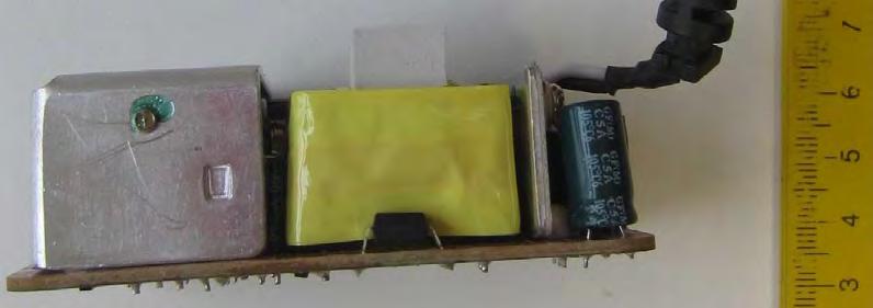

188 age 188 of 226 Report No. T /17 Encl. No. 2


189 age 189 of 226 Report No. T /17 Encl. No. 2


190 age 190 of 226 Report No. T /17 Encl. No. 2
191 age 191 of 226 Report No. T /17 Encl. No. 2
192 age 192 of 226 Report No. T /17 Encl. No. 3 Enclosure No. 3 Schematics, layouts and transformer drawings (35 pages including this cover page)
193 age 193 of 226 Report No. T /17 Encl. No. 3 ower supply unit evaluated for Means of Operator rotection (MOO) (Single Y1 capacitor provided between primary and secondary circuit)

194 age 194 of 226 Report No. T /17 Encl. No. 3
195 age 195 of 226 Report No. T /17 Encl. No. 3

196 age 196 of 226 Report No. T /17 Encl. No. 3

197 age 197 of 226 Report No. T /17 Encl. No. 3
198 age 198 of 226 Report No. T /17 Encl. No. 3

199 age 199 of 226 Report No. T /17 Encl. No. 3
200 age 200 of 226 Report No. T /17 Encl. No. 3
201 age 201 of 226 Report No. T /17 Encl. No. 3
202 age 202 of 226 Report No. T /17 Encl. No. 3
203 age 203 of 226 Report No. T /17 Encl. No. 3
204 age 204 of 226 Report No. T /17 Encl. No. 3
205 age 205 of 226 Report No. T /17 Encl. No. 3
206 age 206 of 226 Report No. T /17 Encl. No. 3
207 age 207 of 226 Report No. T /17 Encl. No. 3
208 age 208 of 226 Report No. T /17 Encl. No. 3
209 age 209 of 226 Report No. T /17 Encl. No. 3
210 age 210 of 226 Report No. T /17 Encl. No. 3
211 age 211 of 226 Report No. T /17 Encl. No. 3

 (Models additionally marked with 2MO near model name)")
212 age 212 of 226 Report No. T /17 Encl. No. 3 ower supply unit evaluated for Means of atient rotection (MO) (Models additionally marked with 2MO near model name) (2 x Y1 capacitors in series provided between primary and secondary circuit)
TEST REPORT IEC Part 1: General requirements for basic safety and essential performance
 Test Report issued under the responsibility of: TEST REORT art 1: General requirements for basic safety and essential performance Report Number.... : T221-0013/17 Date of issue... : 2017-03-31 Total number
Page 3 of 259 Report No
 age 3 of 259 List of Attachments (including a total number of pages in each attachment): Attachment No.1: 10 pages of National Differences for 3 rd editionas per IEC Bulletin. Attachment No.2: 5 pages
TEST REPORT IEC Information technology equipment Safety Part 1: General requirements
 Test Report issued under the responsibility of: TEST REPORT IEC 60950-1 Information technology equipment Safety Part 1: General requirements Report Number.... : 210282-CI3-2 CB DE1-56459 Date of issue...
TEST REPORT IEC Information technology equipment Safety Part 1: General requirements
 Test Report issued under the responsibility of www.nemko.com TEST REPORT IEC 60950-1 Information technology equipment Safety Part 1: General requirements Report Number....: 285573 Date of issue...: 2015-09-15
TEST REPORT IEC Information technology equipment Safety Part 1: General requirements
 Test Report issued under the responsibility of: TEST REPORT IEC 60950-1 Information technology equipment Safety Part 1: General requirements Report Number.... : 207721-AS3-1 CB/DE1-55140 Date of issue...
TEST REPORT IEC Information technology equipment Safety Part 1: General requirements
 Test Report issued under the responsibility of: TEST REPORT IEC 60950-1 Information technology equipment Safety Part 1: General requirements Report Number.... : 212475-CI3-1 CBDE1-52299/A1/M1 Date of issue...
TEST REPORT IEC Information technology equipment Safety Part 1: General requirements
 Test Report issued under the responsibility of: TEST REPORT IEC 60950-1 Information technology equipment Safety Part 1: General requirements Report Number....: T223-0102/16 Date of issue...: 2016-03-15
TEST REPORT IEC60950_1F. Information technology equipment - Safety - Part 1: General requirements
 Issue Date: 2017-05-23 Page 1 of 9 Report Reference # 4787989179 Test Report issued under the responsibility of: TEST REPORT IEC 60950-1 Information technology equipment - Safety - Part 1: General requirements
TEST REPORT IEC Information technology equipment Safety Part 1: General requirements
 Test Report issued under the responsibility of: TEST REPORT IEC 60950-1 Information technology equipment Safety Part 1: General requirements Report Number....: T223-0104/16 Date of issue...: 2016-03-15
TEST REPORT IEC : 2005 (2nd Edition) and/or EN :2006 Information technology equipment Safety Part 1: General requirements
 and/or EN :2006 Information technology equipment Safety Part 1: General requirements") Test Report issued under the responsibility of: TEST REPORT IEC 60950-1: 2005 (2nd Edition) and/or EN 60950-1:2006 Information technology equipment Safety Part 1: General requirements Report Reference
Test Report issued under the responsibility of: TEST REPORT IEC 60950-1: 2005 (2nd Edition) and/or EN 60950-1:2006 Information technology equipment Safety Part 1: General requirements Report Reference
TEST REPORT IEC Information technology equipment - Safety - Part 1: General requirements
 Issue Date: 2015-07-21 Page 1 of 119 Report Reference # 4786910622-5 Test Report issued under the responsibility of: TEST REPORT IEC 60950-1 Information technology equipment - Safety - Part 1: General
IfYcSXY]W!F^fUa!Id [h! IUU!FQWU!,! IB!FEM;H!;B;8JHED?8I!
![IfYcSXY]W!F^fUa!Id [h! IUU!FQWU!,! IB!FEM;H!;B;8JHED?8I!](/thumbs/80/81643598.jpg "IfYcSXY]W!F^fUa!Id [h! IUU!FQWU!,! IB!FEM;H!;B;8JHED?8I!") ! +), HUV(!8UacYV(!D^(.2$(**)$93?;8!IOIJ;C!
! +), HUV(!8UacYV(!D^(.2$(**)$93?;8!IOIJ;C!
IfYcSXY]W!F^fUa!Id [h! IUU!FQWU!,! IB!FEM;H!;B;8JHED?8I! 8J<!IcQWU!+!
![IfYcSXY]W!F^fUa!Id [h! IUU!FQWU!,! IB!FEM;H!;B;8JHED?8I! 8J<!IcQWU!+!](/thumbs/80/81390013.jpg "IfYcSXY]W!F^fUa!Id [h! IUU!FQWU!,! IB!FEM;H!;B;8JHED?8I! 8J<!IcQWU!+!") ! +), HUV(!8UacYV(!D^(.2$)*(($93?;8!IOIJ;C!
! +), HUV(!8UacYV(!D^(.2$)*(($93?;8!IOIJ;C!
TEST REPORT IEC Information technology equipment Safety Part 1: General requirements
 Test Report issued under the responsibility of: TEST REPORT IEC 60950-1 Information technology equipment Safety Part 1: General requirements Report Number....: T223-0042/16 Date of issue...: 2016-03-04
TEST REPORT IEC Audio, video and similar electronic apparatus - Safety requirements
 Test Report issued under the responsibility of www.nemko.com TEST REPORT IEC 60065 Audio, video and similar electronic apparatus - Safety requirements Report Number... : 246847 Date of issue... : October
DE Total. American Inc. IEC Test Report Form. If this. and appended to General disclaimer: the NCB, VDE File. No VDE File.
 1Fdar Test Report issued under the responsibility of: TEST REPORT IEC 60950-1 Information technology equipment Safety Part 1: General requirements Report Number....: 215009-CI3-1 Date of issue...: 2015-07-31
TEST REPORT IEC Information technology equipment - Safety - Part 1: General requirements
 Issue Date: 2015-10-19 Page 1 of 143 Report Reference # 4786910627-9 Test Report issued under the responsibility of: TEST REPORT IEC 60950-1 Information technology equipment - Safety - Part 1: General
Page 2 of 69 VDE Report No.: / DC - DC Converter for building in. TDK Innoveta Inc. iba - Series (see model matrix appendix 1)
") Page 2 of 69 VDE Report No.: 2520400-3336-0009/132550 Test item description... : Trade Mark...: Manufacturer...: Model/Type reference...: Serial Number..: Ratings...: Input: Output: Ambient: DC - DC Converter
Page 2 of 69 VDE Report No.: 2520400-3336-0009/132550 Test item description... : Trade Mark...: Manufacturer...: Model/Type reference...: Serial Number..: Ratings...: Input: Output: Ambient: DC - DC Converter
TEST REPORT IEC Information technology equipment - Safety - Part 1: General requirements
 Issue Date: 2017-05-23 Page 1 of 9 Report Reference # 4787989180 Test Report issued under the responsibility of: TEST REPORT IEC 60950-1 Information technology equipment - Safety - Part 1: General requirements
Amendment to Test Report
 Test Report issued under the responsibility of www.nemko.com Amendment to Test Report This Amendment is valid only together with the main Test Report Report No.... : 270292 Main Report No.... : 261294
TEST REPORT IEC Information technology equipment - Safety - Part 1: General requirements
 Issue Date: 2015-08-10 Page 1 of 27 Report Reference # E122103-A152-CB-2 Test Report issued under the responsibility of: Report Reference No... : TEST REPORT IEC 60950-1 Information technology equipment
TEST REPORT IEC Information technology equipment - Safety - Part 1: General requirements
 Issue Date: 2015-02-26 Page 1 of 61 Report Reference # E122103-A161-CB-1 Test Report issued under the responsibility of: Report Reference No... : TEST REPORT IEC 60950-1 Information technology equipment
TEST REPORT IEC Information technology equipment - Safety - Part 1: General requirements
 Issue Date: 2015-06-25 Page 1 of 78 Report Reference # E122103-A133-CB-2 Test Report issued under the responsibility of: Report Reference No... : TEST REPORT IEC 60950-1 Information technology equipment
TEST REPORT IEC Part 1: General requirements for basic safety and essential performance
 Test Report issued under the responsibility of: TEST REPORT IEC 60601-1 Part 1: General requirements for basic safety and essential performance Report Number.... : E349607-D13-CB-2 Date of issue... : 2017-07-25
SPECIFIC TECHNICAL CRITERIA
 Issue Date: 2009-04-10 Page 3 of 58 Report Reference # E116994-A48-UL-1 SPECIFIC TECHNICAL CRITERIA TEST REPORT UL 60601-1 Medical Electrical Equipment Part 1: General requirements for safety Report Reference
TEST REPORT IEC Safety of Transportable Motor-Operated Power Tools
 Test Report issued under the responsibility of: STAYER IBÉRICA S.A TEST REPORT Safety of Transportable Motor-Operated Power Tools REPORT IDS TR_POTENZA160_SEG_01 Report Reference No. : TR_POTENZA160_SEG_01
TEST REPORT IEC Electromagnetic Compatibility (EMC)
") Test Report issued under the responsibility of: STAYER IBÉRICA S.A TEST REPORT Electromagnetic Compatibility (EMC) REPORT IDS TR_ PLUS_140_EMC_01 Report Reference No. : TR_ PLUS_140_EMC_01 Date of issue...
Test Report issued under the responsibility of: STAYER IBÉRICA S.A TEST REPORT Electromagnetic Compatibility (EMC) REPORT IDS TR_ PLUS_140_EMC_01 Report Reference No. : TR_ PLUS_140_EMC_01 Date of issue...
TEST REPORT IEC Information technology equipment Safety Part 1: General requirements
 Test Report issued under the responsibility of: TEST REORT IEC 60950-1 Information technology equipment Safety art 1: General requirements Report Number.... : T221-0052/16 Date of issue... : 2016-07-14
TEST REPORT IEC Information technology equipment - Safety - Part 1: General requirements
 Issue Date: 2015-05-25 Page 1 of 97 Report Reference # E122103-A147-CB-2 Test Report issued under the responsibility of: Report Reference No... : TEST REPORT IEC 60950-1 Information technology equipment
HAND-HELD MULTIMETERS
 Test Report issued under the responsibility of: TEST REORT IEC 61010-1, and IEC 61010-2-033 Safety requirements for electrical equipment for measurement, control, and laboratory use. art 1: General requirements,
IEC60601_1K. Medical electrical equipment Part 1: General requirements for basic safety and essential performance
 Page 1 of 160 Report No.: E349607-D1007-1/A0/C0-ULCB CB - IEC REPORT: Test Report issued under the responsibility of: IEC 60601-1 Medical electrical equipment Part 1: General requirements for basic safety
TEST REPORT IEC , IEC
 Test Report issued under the responsibility of: TEST REORT IEC 61010-1, IEC 61010-2-032 and IEC 61010-2-033 Safety requirements for electrical equipment for measurement, control, and laboratory use. art
UL International Demko A/S
 Issue Date: 2010-12-01 Page 1 of 56 Report Reference # E252373-A31-CB-1 Test Report issued under the responsibility of: Report Reference No... : TEST REPORT IEC 60950-1 Information technology equipment
TEST REPORT IEC Safety requirements for electrical equipment for measurement, control, and laboratory use Part 1: General requirements
 Issue Date: 2013-07-22 Page 1 of 19 Report Reference # E331788-A13-CB-1 Test Report issued under the responsibility of: TEST REPORT IEC 61010-1 Safety requirements for electrical equipment for measurement,
TEST REPORT IEC Safety of laser products - Part 1: Equipment classification and requirements
 Test Report issued under the responsibility of: TEST REPORT IEC 60825-1 Safety of laser products - Part 1: Equipment classification and requirements Report Number.... : GZES160801248631 Date of issue...
UL International Demko A/S
 Issue Date: 2010-09-08 Page 1 of 8 Report Reference # E252373-A7-CB-2 Test Report issued under the responsibility of: Report Reference No... : TEST REPORT IEC 60950-1 Information technology equipment -
TEST REPORT IEC Medical Electrical Equipment Part 1:General requirements for safety
 Issue Date: 2015-10-09 Page 1 of 124 Report Reference # E349607-A8-CB-2 Test Report issued under the responsibility of: Report Reference No... : TEST REPORT IEC 60601-1 Medical Electrical Equipment Part
TEST REPORT IEC Information technology equipment - Safety - Part 1: General requirements
 Issue Date: 2016-12-19 Page 1 of 38 Report Reference # E122103-A211-CB-1 Test Report issued under the responsibility of: Report Reference No... : TEST REPORT IEC 60950-1 Information technology equipment
TEST REPORT IEC Uninterruptible power systems Part 3: Method of specifying the performance and test requirements
 Test Report issued under the responsibility of: TEST REORT IEC 62040-3 Uninterruptible power systems art 3: Method of specifying the performance and test requirements Report reference No...: 11-EL-0026.06
TEST REPORT IEC Safety requirements for electrical equipment for measurement, control, and laboratory use Part 1: General requirements
 Page 2 of 85 Report No. 222/7112462/2 of 2 TEST REPORT IEC 61010-1 Safety requirements for electrical equipment for measurement, control, and laboratory use Part 1: General requirements Report Reference
TEST REPORT. IEC DC or AC supplied electronic control gear for LED modules Performance requirements
 Test Report issued under the responsibility of: UL International Italia S.r.l. TEST REPORT IEC 62384 DC or AC supplied electronic control gear for LED modules Performance requirements Report Reference
TEST REPORT IEC Adjustable speed electrical power drive systems Part 5-1: Safety requirements Electrical, thermal and energy
 Test Report issued under the responsibility of: TEST REPORT Adjustable speed electrical power drive systems Part 5-1: Safety requirements Electrical, thermal and energy Report Reference No.... : 4787846262
TEST REPORT DIN V VDE V :2006 Automatic disconnecting device
 age 1 of 23 TEST REORT Automatic disconnecting device Report Reference No...: GZ10080033-1 Date of issue...: August 18, 2010 Total number of pages... 23 pages Testing Laboratory...: Address...: Tested
TEST REPORT IEC Medical Electrical Equipment Part 1:General requirements for safety
 Issue Date: Page 1 of 28 Report Reference # E349607-A26-CB-1 Test Report issued under the responsibility of: Report Reference No... : Date of issue... : Total number of pages... : 28 CB Testing Laboratory...
DM-45 Digital Multimeter
 INSTRUCTION MANUAL DM-45 Digital Multimeter Read and understand all of the instructions and safety information in this manual before operating or servicing this tool. Description The Greenlee DM-45 Digital
TEST REPORT IEC Low-voltage switchgear and controlgear - Part 2: Circuit-breakers
 Test Report issued under the responsibility of: TEST REORT Low-voltage switchgear and controlgear - art 2: Circuit-breakers Report Reference No.... : 3305316.50 Date of issue... : 2013-09-17 Total number
EN Information technology equipment Safety Part 1: General requirements
 EN 61010-1 Information technology equipment Safety Part 1: General requirements Report Number....: 14PP083-01_1 Date of issue...: 2013-09-05 Total number of pages... 25 Tested by...: Thomas Rogg (printed
SAUDI STANDARD NO. SASO IEC : 2007 SWITCHES FOR HOUSEHOLD AND SIMILAR FIXED ELECTRICAL INSTALLATIONS
 SAUDI STANDARD NO. SASO IEC 60669-2-2: 2007 SWITCHES FOR HOUSEHOLD AND SIMILAR FIXED ELECTRICAL INSTALLATIONS Part 2-2: Particular requirements Electromagnetic remote-control switches (RCS) SAUDI ARABIAN
SPECIFIC TECHNICAL CRITERIA
 Issue Date: 2007-10-24 Page 1 of 6 Report Reference # E210157-A29-UL-1 SPECIFIC TECHNICAL CRITERIA UL 60950-1, First Edition Information technology equipment - Safety- Part 1: General Requirements Report
IDEAL INDUSTRIES, INC. TECHNICAL MANUAL MODEL: MODEL: Multimeter Service Information
 IDEAL INDUSTRIES, INC. TECHNICAL MANUAL MODEL: 61-340 MODEL: 61-342 Multimeter Service Information The Service Information provides the following information: Precautions and safety information Specifications
USER MANUAL 600A AC Clamp Meter + NCV Model MA610
 USER MANUAL 600A AC Clamp Meter + NCV Model MA610 Additional User Manual Translations available at www.extech.com Introduction Thank you for selecting the Extech MA610 Clamp Meter. This meter measures
TEST REPORT IEC Information technology equipment - Safety - Part 1: General requirements
 Issue Date: 2015-01-12 Page 1 of 107 Report Reference # E252373-A7-CB-4 Test Report issued under the responsibility of: Report Reference No... : TEST REPORT IEC 60950-1 Information technology equipment
INSTITUTE OF TESTING AND CERTIFICATION (INDIA) PVT. LTD.
 PVT. LTD.") (INDIA) VT. LTD. Clause Requirement Test Results Remarks Verdict 5 Marking and documentation 5.1 Marking 5.1.1 General Markings shall be visible from the exterior, or be visible after removing a cover
(INDIA) VT. LTD. Clause Requirement Test Results Remarks Verdict 5 Marking and documentation 5.1 Marking 5.1.1 General Markings shall be visible from the exterior, or be visible after removing a cover
page 2 of 86 Report reference No:
 articulars: test item vs. test requirements 3. Classification 3.1. Utilization category: (A or B)... : A 3.2. Interruption medium: (air, vacuum, gas Break)... : Air 3.3. Design: (open construction, moulded
SI-125 Power Amplifier Manual 6205 Kestrel Road; Mississauga, Ontario; Canada; L5T 2A1 November 2016, Rev 0.5
 SI-125 Power Amplifier Manual 6205 Kestrel Road; Mississauga, Ontario; Canada; L5T 2A1 November 2016, Rev 0.5 Phone: (905) 564-0801 Fax: (905) 564-0806 www.telecor.com E:\T2-108\T2-M108-ABC\T2-M108-B.doc/AD
TEST REPORT EN Safety requirements for electrical equipment for measurement, control, and laboratory use Part 1: General requirements
 age 1 of 81 TEST REORT EN 61010-1 Safety requirements for electrical equipment for measurement, control, and laboratory use art 1: General requirements Report Number.... : S12WR-009 Date of issue... :
AC/DC Clamp Meter. Owner's Manual. Model No Safety Operation Maintenance Español
 Owner's Manual AC/DC Clamp Meter Model No. 82369 CAUTION: Read, understand and follow Safety Rules and Operating Instructions in this manual before using this product. Safety Operation Maintenance Español
SPAC265-8W. AC-DC power supply module. Features. Description. Applications
 AC-DC power supply module Datasheet production data Features Open frame switch mode power supply European input voltage range Single output 5 V, 8 W peak power, 4 W continuous operating mode EMC compliance
 Page 4 of 8 Report No. 11029568 003 Summary of testing: Tests performed (name of test and test clause): All applicable tests as described in Test Case and Measurement Sections were performed. Tests performed
CB Testing Laboratory...:EZÚ Address...:Pod Lisem Praha71-Trója Testing location/ procedure...: CBTL RMT SMT WMT TMP IEC60947_2C
 age 1 of 109 Report No.600332-04/01 TEST REORT Low-voltage switchgear and controlgear art 2: Circuit - breakers Report Reference No....: 600332-04/01 Tested by (name+signature)...:... Witnessed by (name+signature)...:...
INSTRUCTION MANUAL DIGITAL PSC-LOOP TESTER MODEL 4118A KYORITSU ELECTRICAL INSTRUMENTS WORKS,LTD.
 INSTRUCTION MANUAL DIGITAL PSC-LOOP TESTER MODEL 4118A KYORITSU ELECTRICAL INSTRUMENTS WORKS,LTD. CONTENTS 1. SAFE TESTING... 1 2. PROCEDURE OF REMOVING COVER... 4 3. FEATURES... 5 3.1 Instrument Layout...
TEST REPORT IEC Medical Electrical Equipment Part 1:General requirements for basic safety and essential performance
 Issue Date: 2015-01-13 Page 1 of 259 Report Reference # E349607-A14-CB-2 Test Report issued under the responsibility of: TEST REPORT IEC 60601-1 Medical Electrical Equipment Part 1:General requirements
USER'S MANUAL DMR-6700
 USER'S MANUAL Multimeter True RMS DMR-6700 CIRCUIT-TEST ELECTRONICS www.circuittest.com Introduction This meter measures AC/DC Voltage, AC/DC Current, Resistance, Capacitance, Frequency (electrical & electronic),
Instruction Manual ICM 3091N Digital AC Clampmeter EN FR IT DE ES
 Instruction Manual ICM 3091N Digital AC Clampmeter EN FR IT DE ES TABLE OF CONTENTS / EN TITLE TABLE OF CONTENTS PAGE 1. SAFETY INFORMATION... 1 2. TECHNICAL SPECIFICATIONS... 2 3. PARTS & CONTROLS...
Test Report. File No.: SHV01023/16 Test Report No.: Taizhou, Zhejiang , P.R. China
 Applicant... : Manufacturer... : Order No.... : Zhejiang ERA Solar Technology Co., Ltd. Sihai Road, Huangyan Economic Development Zone Taizhou, Zhejiang 318020, P.R. China Zhejiang ERA Solar Technology
Report no GZU-001. Growatt 30000TL3-S, Growatt 30000TL3-SE. Max. input current: 34A/34A 38A/38A
 age 2 of 27 Rating : Model Max. DC input Voltage: 30000TL3-S, 30000TL3-SE 33000TL3-S, 33000TL3-SE Input 1000Vdc 40000TL3- NS, 40000TL3- NSE 50000TL3-S, 50000TL3-SE Max. input current: 34A/34A 38A/38A DC
TEST REPORT IEC Safety of household and similar electrical appliances
 0 Test Report issued under the responsibility of: TEST REORT Safety of household and similar electrical appliances Report Number.... : T211-0704/13 Date of issue... : 2013-12-20 Total number of pages...
MS2030 CAT III 600 V A V AUTO RS232
 MS2030 AC Digital Clamp Meter User s Manual CAT III 600 V AUTO RS232 A V CONTENTS 1.Introduction...1 2.Safety Information...1 2.1 Precautions...1 2.2 Safety Symbols...3 3. Description...4 3.1 Front Panel...4
34134A AC/DC DMM Current Probe. User s Guide. Publication number April 2009
 User s Guide Publication number 34134-90001 April 2009 For Safety information, Warranties, Regulatory information, and publishing information, see the pages at the back of this book. Copyright Agilent
MW3105 DIGITAL CLAMP MULTIMETER
 MW3105 DIGITAL CLAMP MULTIMETER 2 M MW3105 A 01 INTRODUCTION 1.1 - Unpacking and inspection Upon removing your new Digital Clamp Meter from its packing, you should have the following items: 1. Digital
TEST REPORT IEC Part 2: Particular requirements Section Thirteen d.c. or a.c. supplied electronic controlgear for LED modules
 age 1 of 31 Test Report issued under the responsibility of: Intertek Testing Services Shenzhen Ltd. Guangzhou Branch TEST REORT art 2: articular requirements Section Thirteen d.c. or a.c. supplied electronic
TEST REPORT IEC Part 1: General requirements for basic safety and essential performance
 Page 1 of 181 Report No. E349607-D4-CB-1-ORIGINAL Test Report issued under the responsibility of: TEST REPORT IEC 60601-1 Part 1: General requirements for basic safety and essential performance Report
SPECIFIC TECHNICAL CRITERIA
 Issue Date: 2010-05-19 Page 3 of 49 Report Reference # E186249-A51-UL-3 SPECIFIC TECHNICAL CRITERIA UL 60950-1:2005 (2nd Edition) Information technology equipment - Safety - Part 1: General requirements
79/26 Series III Multimeter
 79/26 Series III Multimeter Instruction Sheet W Read First: Safety Information Never use the meter if the meter or test leads look damaged. Be sure the test leads and switch are in the correct position
MS8268 HANDHELD DIGITAL MULTIMETER OPERATOR S INSTRUCTION MANUAL
 MS8268 HANDHELD DIGITAL MULTIMETER OPERATOR S INSTRUCTION MANUAL Table of Contents TITLE PAGE 1. GENERAL INSTRUCTIONS 1 1.1 Precaution safety measures 1 1.1.1 Preliminary 1 1.1.2 During use 2 1.1.3 Symbols
Auftrags-Nr.: Order No.:
 www.tuv.com age 2 of 12 Report No.: 16064278 004 rüfbericht-nr.: Test Report No.: 16064278 004 Auftrags-Nr.: Order No.: 174037713 Seite 2 von 12 age 2 of 12 Sonstiges/ Other Aspects: - This report is based
UL TEST REPORT AND PROCEDURE
 Issue Date: 2013-10-30 Page 1 of 19 Report Reference # E122103-A151-UL UL TEST REPORT AND PROCEDURE Standard: Certification Type: CCN: Complementary CCN: Product: Model: Rating: Applicant Name and Address:
Portable Appliance Testers. OmegaPAT MI 2140 BetaPAT MI 2141 User Manual Ver Code No
 Portable Appliance Testers OmegaPAT MI 2140 BetaPAT MI 2141 User Manual Ver. 1.2. Code No. 20 750 684 Distributor: Producer: METREL d.d. Ljubljanska 77 SI-1354 Horjul E-mail: metrel@metrel.si http://www.metrel.si
Pag 1 of 15. Eurotest Laboratori S.r.l. Via Marconi, Brugine (PD) Italy
 Italy") Pag 1 of 15 TEST REPORT IEC 82/685/NP (not ACCREDIA accredited) IEC 60068-2-78 IEC 61215 IEC 61730-2 System voltage durability test for crystalline silicon modules Design qualification and type approval
Pag 1 of 15 TEST REPORT IEC 82/685/NP (not ACCREDIA accredited) IEC 60068-2-78 IEC 61215 IEC 61730-2 System voltage durability test for crystalline silicon modules Design qualification and type approval
IEC Information technology equipment Safety Part 1: General requirements
 Test Report issued under the responsibility of www.nemko.com TEST REORT IEC 60950-1 Information technology equipment Safety art 1: General requirements Report Number.... : 312253 Date of issue... : 2016-07-11
Model 3725/2M. Line Impedance Stabilization Network (LISN) User Manual
 User Manual") Model 3725/2M Line Impedance Stabilization Network (LISN) User Manual ETS-Lindgren L.P. reserves the right to make changes to any product described herein in order to improve function, design, or for any
Model 3725/2M Line Impedance Stabilization Network (LISN) User Manual ETS-Lindgren L.P. reserves the right to make changes to any product described herein in order to improve function, design, or for any
GETTING STARTED GUIDE NI AI, ±10 V, 24 Bit, 50 ks/s/ch Simultaneous
 GETTING STARTED GUIDE NI 9239 4 AI, ±10 V, 24 Bit, 50 ks/s/ch Simultaneous This document explains how to connect to the NI 9239. Note Before you begin, complete the software and hardware installation procedures
AC/DC Current Probe GCP-100 QUICK START GUIDE ISO-9001 CERTIFIED MANUFACTURER
 AC/DC Current Probe GCP-100 QUICK START GUIDE ISO-9001 CERTIFIED MANUFACTURER This manual contains proprietary information, which is protected by copyright. All rights are reserved. No part of this manual
TEST REPORT IEC : 2005 (2nd Edition) and/or EN :2006 Information technology equipment Safety Part 1: General requirements
 and/or EN :2006 Information technology equipment Safety Part 1: General requirements") Test Report issued under the responsibility of: NCB TÜV SÜD PSB Pte Ltd 1 Science Park Drive, Singapore 118221 TEST REPORT IEC 60950-1: 2005 (2nd Edition) and/or EN 60950-1:2006 Information technology
Test Report issued under the responsibility of: NCB TÜV SÜD PSB Pte Ltd 1 Science Park Drive, Singapore 118221 TEST REPORT IEC 60950-1: 2005 (2nd Edition) and/or EN 60950-1:2006 Information technology
IDEAL INDUSTRIES, INC. TECHNICAL MANUAL MODEL:
 IDEAL INDUSTRIES, INC. TECHNICAL MANUAL MODEL: 61-352 The Service Information provides the following information: Precautions and safety information Specifications Basic maintenance (cleaning, replacing
TEST REPORT EN 62233: 2008 Measurement methods for electromagnetic fields of household appliances and similar apparatus with regard to human exposure
 TEST REORT Measurement methods for electromagnetic fields of household appliances and similar apparatus with regard to human exposure Report Reference No....: GZES110400210331 Tested by (name + signature)...:
Prepared by Mick Maytum
 IEC Technical Committee 109: Standards on insulation co-ordination for low-voltage equipment Warning Prepared by Mick Maytum mjmaytum@gmail.com The document content is of a general nature only and is not
I P. /dt. di p V S Applications. Standards 1) IEC : 2007; IEC : ) IEC : 2016; IEC : 2017
 IEC : 2007; IEC : ) IEC : 2016; IEC : 2017") Ref: ART-B22-D70, ART-B22-D125, ART-B22-D175, ART-B22-D300 Flexible clip-around Rogowski coil for the electronic measurement of AC current with galvanic separation between the primary circuit (power) and
Ref: ART-B22-D70, ART-B22-D125, ART-B22-D175, ART-B22-D300 Flexible clip-around Rogowski coil for the electronic measurement of AC current with galvanic separation between the primary circuit (power) and
CBA 400M MHZ to 400 MHZ
 1 CBA 400M-100 1 MHZ to 400 MHZ 100 watt amplifier user Manual 601-298A CBA 400M-100 1 MHZ to 400 MHZ 100 watt amplifier USER Manual CBA 400M-100 User Manual contents 1 Safety information 5 2 Introduction
GETTING STARTED GUIDE NI AI, ±60 V, 24 Bit, 1 ks/s/ch Simultaneous
 GETTING STARTED GUIDE NI 9228 8 AI, ±60 V, 24 Bit, 1 ks/s/ch Simultaneous This document explains how to connect to the NI 9228. Note Before you begin, complete the software and hardware installation procedures
400Amp True RMS AC Clamp Meter + NCV
 User Guide 400Amp True RMS AC Clamp Meter + NCV Model MA410T Introduction Thank you for selecting the Extech MA410 Clamp Meter. This meter measures AC Current, AC/DC Voltage, Resistance, Capacitance, Frequency,
Summary of testing: The product has been tested according to standard IEC : 2010 & IEC : 2011.
 Summary of testing: The product has been tested according to standard IEC 62109-1: 2010 & IEC 62109-2: 2011. List of Attachments (including a total number of pages in each attachment): This test report
RIGOL. User s Guide. RP1000D Series High Voltage Differential Probe. Feb RIGOL Technologies, Inc
 User s Guide RP1000D Series High Voltage Differential Probe Feb. 2013 RIGOL Technologies, Inc Guaranty and Declaration Copyright 2012 RIGOL Technologies, Inc. All Rights Reserved. Trademark Information
HAWK5000 Operators Manual
 HAWK5000 Operators Manual Keison Products P.O. Box 2124, Chelmsford CM1 3UP, England Tel: +44 (0) 1245 600560 Fax: +44 (0) 1245 600030 Email: sales@keison.co.uk www.keison.co.uk KANE INTERNATIONAL LIMITED
User s Manual. Miniature Passive Probe. IM EN 3rd Edition
 User s Manual Miniature Passive Probe IM 701946-01EN 3rd Edition Thank you for purchasing the miniature passive probe. This miniature passive probe is designed for user s safety and excellent easyto-use
INSTRUCTION MANUAL LKG 601 Electrical Safety Analyzer
 INSTRUCTION MANUAL LKG 601 Electrical Safety Analyzer 110 Toledo Street Farmingdale, NY 11735 USA http://www.netech.org 510-USER-Manual Rev3 10/29/2007 Dear User, We appreciate your purchase of the LKG
TEST REPORT IEC Part 2: Particular requirements Section Thirteen d.c. or a.c. supplied electronic controlgear for LED modules
 age 1 of 38 Test Report issued under the responsibility of: Intertek Testing Services Shenzhen Ltd. Guangzhou Branch TEST REORT art 2: articular requirements Section Thirteen d.c. or a.c. supplied electronic
AM-510 Commercial / Residential Multimeter. AM-510-EUR Digital Multimeter. Users Manual
 AM-510 Commercial / Residential Multimeter AM-510-EUR Digital Multimeter Users Manual AM-510 Commercial / Residential Multimeter AM-510-EUR Digital Multimeter English Users Manual Limited Warranty and
IGS IGS-M-EL-22(1) Contactors APPROVED. Iranian Gas Standards
 Contactors APPROVED. Iranian Gas Standards") APPROVED IGS Iranian Gas Standards Contactors. Fax:(9821)-8131-5679 --. /012 34-52673892 :;395- 8? /@A7 B;CD /E FGH 34-52673892I2
APPROVED IGS Iranian Gas Standards Contactors. Fax:(9821)-8131-5679 --. /012 34-52673892 :;395- 8? /@A7 B;CD /E FGH 34-52673892I2
MODEL 3810/2 Line Impedance Stabilization Network
 EMC TEST SYSTEMS FEBRUARY 1996 REV C PN 399197 MODEL 3810/2 Line Impedance Stabilization Network OPERATION MANUAL USA P.O. Box 80589 Austin, Texas 78708-0589 2205 Kramer Lane, Austin, Texas 78758-4047