TEST REPORT IEC Safety of household and similar electrical appliances
|
|
|
- Ronald Taylor
- 6 years ago
- Views:
Transcription

1 0 Test Report issued under the responsibility of: TEST REORT Safety of household and similar electrical appliances Report Number.... : T /13 Date of issue... : Total number of pages... : 160 Applicant s name... : Address... : Egston System Electronics Eggenburg GmbH Grafenberger Strasse 37, A-3730 Eggenburg, Austria Test specification: Standard... : Test procedure... : Non-standard test method..: Test Report Form No.... : Test Report Form(s) Originator... : :2010 (Fifth Edition) CB Scheme IEC60335_1T Nemko AS Master TRF... : Dated Copyright 2013 Worldwide System for Conformity Testing and Certification of Electrotechnical Equipment and Components (IECEE), Geneva, Switzerland. All rights reserved. This publication may be reproduced in whole or in part for non-commercial purposes as long as the IECEE is acknowledged as copyright owner and source of the material. IECEE takes no responsibility for and will not assume liability for damages resulting from the reader's interpretation of the reproduced material due to its placement and context. If this Test Report Form is used by non-iecee members, the IECEE/IEC logo and the reference to the CB Scheme procedure shall be removed. This report is not valid as a CB Test Report unless signed by an approved CB Testing Laboratory and appended to a CB Test Certificate issued by an NCB in accordance with IECEE 02. Test item description... : Trade Mark... : Manufacturer... : Open Frame Switch Mode ower Supply EGSTON Model/Type reference... : E20FxW3 60 Ratings... : Egston System Electronics Eggenburg GmbH Input: V~; 1,4-0,7 A; 50/60 Hz Output: Output voltage: 12 V d.c. to 24 V d.c.; Output current: 2,5 A to 5,0 A; Maximum output power: 60 W;
2 -~ age 2 of 160 Report No. T !13 Testing procedure and testing location: [8J CB Testing Laboratory: SIQ - Slovenian Institute of Quality and Metrology, Ljubljana Testing Laboratory is accredited by Siovenian Accreditation, Reg. No.: L-009 Testing location! address... : Trzaska cesta 2, SI-1000 Ljubljana, Slovenia D Associated CB Testing Laboratory: Testing location! address... : D Tested by (name + signature)... : Bostjan Grum ~ Tested by (name + signature)... : Tibor Kokelj (/.~ /~, Approved by (name + signature)... : Tomaz Knez V:~7L. '""--7 u 1-7 Testing procedure: TM Testing location! address... : D Tested by (name + signature)... : Approved by (name + signature)... : Testing procedure: WMT Testing location! address... : D Tested by (name + signature)... : Witnessed by (name + signature)... : Approved by (name + signature)... : Testing procedure: SMT Testing location! address... : Tested by (name + signature)... : Approved by (name + signature)... : Supervised by (name + signature)... : TRF No. IEC60335_H
3 age 3 of 160 Report No. T /13 List of Attachments (including a total number of pages in each attachment): 1. Schematics, layouts, user manual, technical documentation Attachment No. 1; 2. hotos Attachment No. 2; 3. Annex BB extract from IEC :2009 Attachment No. 3; Summary of testing: Tests performed (name of test and test clause): All applicable clauses see test report for details. Testing location: Slovenian Institute of Quality and Metrology, Ljubljana Tržaška cesta 2 SI-1000 Ljubljana Slovenia Summary of compliance with National Differences List of countries addressed: Norway, all Cenelec countires, Ireland, United Kingdom The product fulfils the requirements of :2010 (5 th edition) The product fulfils the requirements of EN :2012 (5 th edition)
 Label on primary heatsink (12 V d.c. / 5 A): b) Label on primary heatsink (24 V d.")
4 age 4 of 160 Report No. T /13 Copy of marking plate The artwork below may be only a draft. The use of certification marks on a product must be authorized by the respective NCBs that own these marks. a) Label on primary heatsink (12 V d.c. / 5 A): b) Label on primary heatsink (24 V d.c. / 2,5 A):
5 age 5 of 160 Report No. T /13 Test item particulars... : Egston System Electronics Eggenburg GmbH Classification of installation and use... : Class I Supply Connection... : terminals... : ossible test case verdicts: - test case does not apply to the test object... : - test object does meet the requirement... : (ass) - test object does not meet the requirement... : F (Fail) Testing... : Date of receipt of test item... : Date (s) of performance of tests... : From to General remarks: The test results presented in this report relate only to the object tested. This report shall not be reproduced, except in full, without the written approval of the Issuing testing laboratory. "(See Attachment No. #)" refers to additional information appended to the report. "(See appended table)" refers to a table appended to the report. Throughout this report a comma / point is used as the decimal separator. Manufacturer s Declaration per sub-clause of IECEE 02: The application for obtaining a CB Test Certificate includes more than one factory location and a declaration from the Manufacturer stating that the sample(s) submitted for evaluation is (are) representative of the products from each factory has been provided... : Yes Not applicable When differences exist; they shall be identified in the General product information section. Name and address of factory (ies)... : 1. EGSTON System Electronics spol.s.r.o., rümyslová 20, Znojmo, Czech Republic
6 age 6 of 160 Report No. T /13 General product information: Essential performance shall be determined within the end equipment. Open Frame Switch Mode ower Supply E20FxW3 60 provides internally two fuses in line and neutral: F1, F2: T3,15 A 250 Vac Open Frame Switch Mode ower Supply E20FxW3 60 was evaluated for: - Reinforced insulation between primary and secondary circuit. - Basic insulation between primary circuit and protective earth. Secondary output circuit is separated from mains by reinforced insulation and rated SELV. The manual has to be part of end product (Open Frame Switch Mode ower Supply E20FxW3 60 is not end product). Open Frame Switch Mode ower Supply E20FxW3 60 is rated class I and shall be properly bonded to the main protective bonding termination in the end product. The earth leakage current is within the specified limits. Touch current measured on output plus and output minus only for reference. The transformer T1 provides reinforced insulation. This transformer is built up to fulfil the requirement of insulation class B. Triple insulated wire (TIW) used for secondary windings. See list of safety critical components. Open Frame Switch Mode ower Supply E20FxW3 60 has been evaluated for use in a ollution Degree 2 and overvoltage category II environment and a maximum altitude of 3000 m. A suitable Electrical and Fire enclosure shall be provided in the end equipment. The product was evaluated for a maximum ambient of 50 C with nominal output power and for maximum ambient temperature of 70 C with output derating 2,5%/ C (for 50 C to 70 C ambient temperature). Approval within the end product: - Leakage current measurement should be verified with the unit built into the end product. History sheet Report No. Date Change Revision No. T / Initial test report issued. --
7 age 7 of 160 Report No. T /13 5 GENERAL CONDITIONS FOR THE TESTS Tests performed according to clause 5, e.g. nature of supply, sequence of testing, etc. 6 CLASSIFICATION 6.1 rotection against electric shock: Class 0, 0I, I, II, III : Class I 6.2 rotection against harmful ingress of water I00 7 MARKING AND INSTRUCTIONS 7.1 Rated voltage or voltage range (V) : V~ Symbol for nature of supply, or : ~ Rated frequency (Hz) : Hz Rated power input (W), or : Rated current (A) : 1,4-0,7 A Manufacturer's or responsible vendor's name, trademark or identification mark : EGSTON Model or type reference : E20FxW3 60 Symbol IEC , for class II appliances I number, other than IX : I00 Symbol IEC , for class III appliances, unless the appliance is operated by batteries only Symbol IEC , for the enclosure of electrically-operated water valves in external hosesets for connection of an appliance to the water mains, if the working voltage exceeds extra-low voltage 7.2 Warning for stationary appliances for multiple supply Warning placed in vicinity of terminal cover 7.3 Range of rated values marked with the lower and upper limits separated by a hyphen Different rated values marked with the values separated by an oblique stroke 7.4 Appliances adjustable for different rated voltages, the voltage setting is clearly discernible Requirement met if frequent changes are not required and the rated voltage to which the appliance is to be adjusted is determined from a wiring diagram
8 age 8 of 160 Report No. T / Appliances with more than one rated voltage or one or more rated voltage ranges, marked with rated input or rated current for each rated voltage or range, unless the power input is related to the arithmetic mean value of the rated voltage range Relation between marking for upper and lower limits of rated power input or rated current and voltage is clear Marked input voltage range and input current range 7.6 Correct symbols used Symbol for nature of supply placed next to rated voltage Symbol for class II appliances placed unlikely to be confused with other marking Units of physical quantities and their symbols according to international standardized system 7.7 Connection diagram fixed to appliances to be connected to more than two supply conductors and appliances for multiple supply, unless correct mode of connection is obvious 7.8 Except for type Z attachment, terminals for connection to the supply mains indicated as follows: - marking of terminals exclusively for the neutral conductor (letter N) - marking of protective earthing terminals (symbol IEC ) - marking not placed on removable parts 7.9 Marking or placing of switches which may cause a hazard 7.10 Indications of switches on stationary appliances and controls on all appliances by use of figures, letters or other visual means : This applies also to switches which are part of a control If figures are used, the off position indicated by the figure 0 The figure 0 indicates only OFF position, unless no confusion with the OFF position 7.11 Indication for direction of adjustment of controls 7.12 Instructions for safe use provided Details concerning precautions during user maintenance -
9 age 9 of 160 Report No. T /13 The instructions state that: - - the appliance is not to be used by persons (including children) with reduced physical, sensory or mental capabilities, or lack of experience and knowledge, unless they have been given supervision or instruction - children being supervised not to play with the appliance For a part of class III construction supplied from a detachable power supply unit, the instructions state that the appliance is only to be used with the unit provided Instructions for class III appliances state that it must only be supplied at SELV, unless it is a battery-operated appliance, the battery being charged outside the appliance Sufficient details for installation supplied For an appliance intended to be permanently connected to the water mains and not connected by a hose-set, this is stated Stationary appliances not fitted with means for disconnection from the supply mains having a contact separation in all poles that provide full disconnection under overvoltage category III, the instructions state that means for disconnection must be incorporated in the fixed wiring in accordance with the wiring rules Insulation of the fixed wiring in contact with parts exceeding 50 K during clause 11; instructions state that the fixed wiring must be protected Instructions for built-in appliances: - - dimensions of space See technical documentation - dimensions and position of supporting and fixing See technical documentation - minimum distances between parts and surrounding structure - minimum dimensions of ventilating openings and arrangement - connection to supply mains and interconnection of separate components - allow disconnection of the appliance after installation, by accessible plug or a switch in the fixed wiring, unless See technical documentation Four holes in CB intended for fixing a switch complying with 24.3 No switch
10 age 10 of 160 Report No. T / Replacement cord instructions, type X attachment with a specially prepared cord Replacement cord instructions, type Y attachment Replacement cord instructions, type Z attachment Caution in the instructions for appliances incorporating a non-self-resetting thermal cut-out that is reset by disconnection of the supply mains, if this cut-out is required to comply with the standard Instructions for fixed appliances stating how the appliance is to be fixed Instructions for appliances connected to the water mains: - - max. inlet water pressure (a) : - min. inlet water pressure, if necessary (a)... : Instructions concerning new and old hose-sets for appliances connected to the water mains by detachable hose-sets 7.13 Instructions and other texts in an official language In English language 7.14 Marking clearly legible and durable, rubbing test as specified 7.15 Markings on a main part Marking clearly discernible from the outside, if necessary after removal of a cover For portable appliances, cover can be removed or opened without a tool For stationary appliances, name, trademark or identification mark and model or type reference visible after installation For fixed appliances, name, trademark or identification mark and model or type reference visible after installation according to the instructions Indications for switches and controls placed on or near the components. Marking not on parts which can be positioned or repositioned in such a way that the marking is misleading 7.16 Marking of a possible replaceable thermal link or fuse link clearly visible with regard to replacing the link 8 ROTECTION AGAINST ACCESS TO LIVE ARTS 8.1 Adequate protection against accidental contact with live parts Requirement applies for all positions, detachable parts removed No detachable parts
11 age 11 of 160 Report No. T /13 Lamps behind a detachable cover not removed, if conditions met Insertion or removal of lamps, protection against contact with live parts of the lamp cap Use of test probe B of IEC 61032, with a force not exceeding 1 N: no contact with live parts Use of test probe B of IEC through openings, with a force of 20N: no contact with live parts Use of test probe 13 of IEC 61032, with a force not exceeding 1 N, through openings in class 0 appliances and class II appliances/constructions: no contact with live parts Test probe 13 also applied through openings in earthed metal enclosures having a non-conductive coating: no contact with live parts For appliances other than class II, use of test probe 41 of IEC 61032, with a force not exceeding 1 N: no contact with live parts of visible glowing heating elements Accessible part not considered live if: - - safety extra-low a.c. voltage: peak value not exceeding 42.4 V - safety extra-low d.c. voltage: not exceeding 42.4 V - or separated from live parts by protective impedance If protective impedance: d.c. current not exceeding 2 ma, and a.c. peak value not exceeding 0.7 ma 0,2 mapk - for peak values over 42.4 V up to and including 450 V, capacitance not exceeding 0,1 µf - for peak values over 450 V up to and including 15 kv, discharge not exceeding 45 µc - for peak values over 15 kv, the energy in the discharge not exceeding 350 mj Live parts protected at least by basic insulation before installation or assembly: - - built-in appliances - fixed appliances - appliances delivered in separate units
12 age 12 of 160 Report No. T / Class II appliances and constructions constructed so that there is adequate protection against accidental contact with basic insulation and metal parts separated from live parts by basic insulation only Only possible to touch parts separated from live parts by double or reinforced insulation 9 STARTING OF MOTOR-OERATED ALIANCES Requirements and tests are specified in part 2 when necessary 10 OWER INUT AND CURRENT 10.1 ower input at normal operating temperature, rated voltage and normal operation not deviating from rated power input by more than shown in table 1. : Test carried out at upper and lower limits of the ranges for appliances with one or more rated voltage ranges, unless the rated power input is related to the arithmetic mean value 10.2 Current at normal operating temperature, rated voltage and normal operation not deviating from rated current by more than shown in table 2... : Test carried out at upper and lower limits of the ranges for appliances with one or more rated voltage ranges, unless the rated current is related to the arithmetic mean value of the range (see appended table) (see appended table) 11 HEATING 11.1 No excessive temperatures in normal use 11.2 The appliance is held, placed or fixed in position as described... : 11.3 Temperature rises, other than of windings, determined by thermocouples Temperature rises of windings determined by resistance method, unless the windings are non-uniform or it is difficult to make the necessary connections 11.4 Heating appliances operated under normal operation at 1.15 times rated power input (W)... : 11.5 Motor-operated appliances operated under normal operation at most unfavourable voltage between 0.94 and 1.06 times rated voltage (V)... : 94 V and 254,4 V
13 age 13 of 160 Report No. T / Combined appliances operated under normal operation at most unfavourable voltage between 0.94 and 1.06 times rated voltage (V)... : 11.7 Operation duration corresponding to the most unfavourable conditions of normal use 11.8 Temperature rises monitored continuously and not exceeding the values in table 3... : If the temperature rise of a motor winding exceeds the value of table 3, or if there is doubt with regard to classification of insulation, tests of Annex C are carried out Sealing compound does not flow out rotective devices do not operate, except components in protective electronic circuits tested for the number of cycles specified in (see appended table) 13 LEAKAGE CURRENT AND ELECTRIC STRENGTH AT OERATING TEMERATURE 13.1 Leakage current not excessive and electric strength adequate Heating appliances operated at 1.15 times the rated power input (W)... : Motor-operated appliances and combined appliances supplied at 1.06 times the rated voltage (V)... : rotective impedance and radio interference filters disconnected before carrying out the tests 13.2 For class 0, class II and class III appliances, leakage current measured by means of the circuit described in figure 4 of IEC For other appliances, a low impedance ammeter may be used 254,4 V Leakage current measurements... : (see appended table) 13.3 The appliance is disconnected from the supply Electric strength tests according to table 4... : (see appended table) No breakdown during the tests 14 TRANSIENT OVERVOLTAGES Appliances withstand the transient over-voltages to which they may be subjected
14 age 14 of 160 Report No. T /13 Clearances having a value less than specified in table 16 subjected to an impulse voltage test, the test voltage specified in table 6... : No flashover during the test, unless of functional insulation if the appliance complies with clause 19 with the clearance short-circuited (see appended table) 15 MOISTURE RESISTANCE 15.1 Enclosure provides the degree of moisture protection according to classification of the appliance Compliance checked as specified in , taking into account , followed by the electric strength test of 16.3 No trace of water on insulation which can result in a reduction of clearances or creepage distances below values specified in clause Appliances, other than IX0, subjected to tests as specified in IEC : Water valves containing live parts in external hoses for connection of an appliance to the water mains tested as specified for IX7 appliances Hand-held appliance turned continuously through the most unfavourable positions during the test Built-in appliances installed according to the instructions Appliances placed or used on the floor or table placed on a horizontal unperforated support Appliances normally fixed to a wall and appliances with pins for insertion into socket-outlets are mounted on a wooden board For IX3 appliances, the base of wall mounted appliances is placed at the same level as the pivot axis of the oscillating tube For IX4 appliances, the horizontal centre line of the appliance is aligned with the pivot axis of the oscillating tube, and for appliances normally used on the floor or table, the movement is limited to two times 90 for a period of 5 min, the support being placed at the level of the pivot axis of the oscillating tube Wall-mounted appliances, take into account the distance to the floor stated in the instructions I00
15 age 15 of 160 Report No. T /13 Appliances normally fixed to a ceiling are mounted underneath a horizontal unperforated support, the pivot axis of the oscillating tube located at the level of the underside of the support, and for IX4 appliances, the movement of the tube is limited to two times 90 from the vertical for a period of 5 min Appliances with type X attachment fitted with a flexible cord as described Detachable parts subjected to the relevant treatment with the main part However, if a part has to be removed for user maintenance and a tool is needed, this part is not removed 15.2 Spillage of liquid does not affect the electrical insulation Appliances with type X attachment fitted with a flexible cord as described Appliances incorporating an appliance inlet tested with or without an connector, whichever is most unfavourable Detachable parts are removed Overfilling test with additional amount of water, over a period of 1 min (l)... : The appliance withstands the electric strength test of 16.3 No trace of water on insulation that can result in a reduction of clearances or creepage distances below values specified in clause Appliances proof against humid conditions Checked by test Cab: Damp heat steady state in IEC Detachable parts removed and subjected, if necessary, to the humidity test with the main part Humidity test for 48 h in a humidity cabinet Reassembly of those parts that may have been removed The appliance withstands the tests of clause LEAKAGE CURRENT AND ELECTRIC STRENGTH 16.1 Leakage current not excessive and electric strength adequate
16 age 16 of 160 Report No. T /13 rotective impedance disconnected from live parts before carrying out the tests Tests carried out at room temperature and not connected to the supply 16.2 Single-phase appliances: test voltage 1.06 times rated voltage (V)... : Three-phase appliances: test voltage 1.06 times rated voltage divided by 3 (V)... : 254,4 V; 60 Hz Leakage current measurements... : (see appended table) Limit values doubled if: - - all controls have an off position in all poles, or - the appliance has no control other than a thermal cut-out, or - all thermostats, temperature limiters and energy regulators do not have an off position, or - the appliance has radio interference filters With the radio interference filters disconnected, the leakage current do not exceed limits specified... : (see appended table) 16.3 Electric strength tests according to table 7... : (see appended table) Test voltage applied between the supply cord and inlet bushing and cord guard and cord anchorage as specified... : No breakdown during the tests (see appended table) 17 OVERLOAD ROTECTION OF TRANSFORMERS AND ASSOCIATED CIRCUITS No excessive temperatures in transformer or associated circuits in event of short-circuits likely to occur in normal use... : Appliance supplied with 1.06 or 0.94 times rated voltage under the most unfavourable short-circuit or overload likely to occur in normal use (V)... : Basic insulation is not short-circuited Temperature rise of insulation of the conductors of safety extra-low voltage circuits not exceeding the relevant value specified in table 3 by more than 15 K Temperature of the winding not exceeding the value specified in table 8 However, limits do not apply to fail-safe transformers complying with sub-clause 15.5 of IEC (see appended table) 18 ENDURANCE
17 age 17 of 160 Report No. T /13 Requirements and tests are specified in part 2 when necessary 19 ABNORMAL OERATION 19.1 The risk of fire, mechanical damage or electric shock under abnormal or careless operation obviated Electronic circuits so designed and applied that a fault will not render the appliance unsafe... : Appliances incorporating heating elements subjected to the tests of 19.2 and 19.3, and if the appliance also has a control that limit the temperature during clause 11 it is subjected to the test of 19.4, and if applicable, to the test of 19.5 Appliances incorporating TC heating elements are also subjected to the test of 19.6 Appliances incorporating motors subjected to the tests of 19.7 to 19.10, as applicable Appliances incorporating electronic circuits subjected to the tests of and 19.12, as applicable Appliances incorporating contactors or relays subjected to the test of 19.14, being carried out before the tests of Appliances incorporating voltage selector switches subjected to the test of Unless otherwise specified, the tests are continued until a non-self-resetting thermal cut-out operates, or until steady conditions are established If a heating element or intentionally weak part becomes open-circuited, the relevant test is repeated on a second sample 19.2 Test of appliances with heating elements with restricted heat dissipation; test voltage (V), power input of 0.85 times rated power input (W)... : 19.3 Test of 19.2 repeated; test voltage (V), power input of 1.24 times rated power input (W)... : 19.4 Test conditions as in clause 11, any control limiting the temperature during tests of clause 11 short-circuited (see appended table)
18 age 18 of 160 Report No. T / Test of 19.4 repeated on Class 0I and I appliances with tubular sheathed or embedded heating elements. No short-circuiting, but one end of the element connected to the sheath The test repeated with reversed polarity and the other end of the heating element connected to the sheath The test is not carried out on appliances intended to be permanently connected to fixed wiring and on appliances where an all-pole disconnection occurs during the test of Appliances with TC heating elements tested at rated voltage, establishing steady conditions The working voltage of the TC heating element is increased by 5% and the appliance is operated until steady conditions are re-established. The voltage is then increased in similar steps until 1.5 times working voltage or until the TC heating element ruptures (V)... : 19.7 Stalling test by locking the rotor if the locked rotor torque is smaller than the full load torque, or locking moving parts of other appliances Locked rotor, capacitors open-circuited one at a time Test repeated with capacitors short-circuited one at a time, unless capacitor is of class 2 of IEC Appliances with timer or programmer supplied with rated voltage for each of the tests, for a period equal to the maximum period allowed... : Other appliances supplied with rated voltage for a period as specified... : Winding temperatures not exceeding values specified in table 8... : 19.8 Multi-phase motors operated at rated voltage with one phase disconnected 19.9 Running overload test on appliances incorporating motors intended to be remotely or automatically controlled or liable to be operated continuously Motor-operated and combined appliances for which is applicable and that use overload protective devices relying on electronic circuits to protect the motor windings, are also subjected to the test (see appended table)
19 age 19 of 160 Report No. T /13 Winding temperatures not exceeding values as specified... : Series motor operated at 1.3 times rated voltage for 1 min (V)... : During the test, parts not being ejected from the appliance Electronic circuits, compliance checked by evaluation of the fault conditions specified in for all circuits or parts of circuits, unless they comply with the conditions specified in Appliances incorporating an electronic circuit that relies upon a programmable component to function correctly, subjected to the test of , unless restarting does not result in a hazard Appliances having a device with an off position obtained by electronic disconnection, or a device placing the appliance in a stand-by mode, subjected to the tests of If the safety of the appliance under any of the fault conditions depends on the operation of a miniature fuse-link complying with IEC 60127, the test of is carried out (see appended table) During and after each test the following is checked: - - the temperature of the windings do not exceed the values specified in table 8 - the appliance complies with the conditions specified in any current flowing through protective impedance not exceeding the limits specified in If a conductor of a printed board becomes open-circuited, the appliance is considered to have withstood the particular test, provided both of the following conditions are met: - the base material of the printed circuit board withstands the test of Annex E - any loosened conductor does not reduce clearance or creepage distances between live parts and accessible metal parts below the values specified in clause Fault conditions a) to g) in are not applied to circuits or parts of circuits meeting both of the following conditions: - the electronic circuit is a low-power circuit, that is, the maximum power at low-power points does not exceed 15 W according to the tests specified - -
20 age 20 of 160 Report No. T /13 - the protection against electric shock, fire hazard, mechanical hazard or dangerous malfunction of other parts of the appliance does not rely on the correct functioning of the electronic circuit Fault conditions applied one at a time, the appliance operating under conditions specified in clause 11, but supplied at rated voltage, duration of the tests as specified: a) short circuit of functional insulation if clearances or creepage distances are less than the values specified in clause 29 b) open circuit at the terminals of any component c) short circuit of capacitors, unless they comply with IEC d) short circuit of any two terminals of an electronic component, other than integrated circuits This fault condition is not applied between the two circuits of an optocoupler e) failure of triacs in the diode mode f) failure of microprocessors and integrated circuits g) failure of an electronic power switching device Each low power circuit is short-circuited by connecting the low-power point to the pole of the supply source from which the measurements were made If the appliance incorporates a protective electronic circuit which operates to ensure compliance with clause 19, the relevant test is repeated with a single fault simulated, as indicated in a) to g) of Appliances having a device with an off position obtained by electronic disconnection, or a device that can be placed in the stand-by mode, subjected to the tests of to , the device being set in the off position or in the stand-by mode Appliances incorporating a protective electronic circuit subjected to the tests of to , the tests being carried out after the protective electronic circuit has operated, except that appliances operated for 30 s or 5 min during the test of 19.7 are not subjected to the tests for electromagnetic phenomena. Surge protective devices disconnected, unless -
21 age 21 of 160 Report No. T /13 They incorporate spark gaps The appliance is subjected to electrostatic discharges in accordance with IEC , test level The appliance is subjected to radiated fields in accordance with IEC , test level The appliance is subjected to fast transient bursts in accordance with IEC , test level 3 or 4 as specified The power supply terminals of the appliance subjected to voltage surges in accordance with IEC , test level 3 or 4 as specified Earthed heating elements in class I appliances disconnected The appliance is subjected to injected currents in accordance with IEC , test level Appliances having a rated current not exceeding 16 A are subjected to the Class 3 voltage dips and interruptions in accordance with IEC Appliances having a rated current exceeding 16 A are subjected to the Class 3 voltage dips and interruptions in accordance with IEC The appliance is subjected to mains signals in accordance with IEC , test level class The appliance is supplied at rated voltage and operated under normal operation. After 60s the power supply is reduced to a level such that the appliance ceases to respond or parts controlled by the programmable component cease to operate The appliance continues to operate normally, or requires a manual operation to restart If the safety of the appliance for any of the fault conditions specified in depends on the operation of a miniature fuse-link complying with IEC 60127, the test is repeated, measuring the current flowing through the fuse-link; measured current (A); rated current of the fuse-link (A)... : During the tests the appliance does not emit flames, molten metal, poisonous or ignitable gas in hazardous amounts Temperature rises not exceeding the values shown in table 9... : Compliance with clause 8 not impaired Measured: > 16 A; rated 3,15 A (see appended table)
22 age 22 of 160 Report No. T /13 If the appliance can still be operated it complies with 20.2 Insulation, other than of class III appliances or class III constructions that do not contain live parts, withstands the electric strength test of 16.3, the test voltage as specified in table 4: - basic insulation (V)... : 1285 V (Working voltage: 278 V) - supplementary insulation (V)... : 1785 V (Working voltage: 278 V) - reinforced insulation (V)... : 3070 V (Working voltage: 278 V) After operation or interruption of a control, clearances and creepage distances across the functional insulation withstand the electric strength test of 16.3, the test voltage being twice the working voltage The appliance does not undergo a dangerous malfunction, and no failure of protective electronic circuits, if the appliance is still operable Appliances tested with an electronic switch in the off position, or in the stand-by mode: - do not become operational, or - if they become operational, do not result in a dangerous malfunction during or after the tests of If the appliance contains lids or doors that are controlled by one or more interlocks, one of the interlocks may be released provided that: - the lid or door does not move automatically to an open position when the interlock is released, and - the appliance does not start after the cycle in which the interlock was released Appliances operated under the conditions of clause 11, any contactor or relay contact operating under the conditions of clause 11 being short-circuited For a relay or contactor with more than one contact, all contacts are short-circuited at the same time A relay or contactor operating only to ensure the appliance is energized for normal use is not shortcircuited If more than one relay or contactor operates in clause 11, they are short-circuited in turn - - -
23 age 23 of 160 Report No. T / For appliances with a mains voltage selector switch, the switch is set to the lowest rated voltage position and the highest value of rated voltage is applied 20 STABILITY AND MECHANICAL HAZARDS 20.1 Appliances having adequate stability Tilting test through an angle of 10, appliance placed on an inclined plane/horizontal support, not connected to the supply mains; appliance does not overturn Tilting test repeated on appliances with heating elements, angle of inclination increased to 15 ossible heating test in overturned position; temperature rise does not exceed values shown in table Moving parts adequately arranged or enclosed as to provide protection against personal injury rotective enclosures, guards and similar parts are non-detachable, and have adequate mechanical strength Enclosures that can be opened by overriding an interlock are considered to be detachable parts Self-resetting thermal cut-outs and overcurrent protective devices not causing a hazard by unexpected closure Not possible to touch dangerous moving parts with the test probe described Unit is intended for building in. 21 MECHANICAL STRENGTH 21.1 Appliance has adequate mechanical strength and is constructed as to withstand rough handling Checked by applying 3 blows to every point of the enclosure like to be weak, in accordance with test Ehb of IEC , spring hammer test, with an impact energy of 0,5 J The appliance shows no damage impairing compliance with this standard, and compliance with 8.1, 15.1 and clause 29 not impaired If doubt, supplementary or reinforced insulation subjected to the electric strength test of 16.3 If necessary, repetition of groups of three blows on a new sample Open frame power supply (see appended table)
24 age 24 of 160 Report No. T / Accessible parts of solid insulation having strength to prevent penetration by sharp implements Test not applicable if the thickness of supplementary insulation is at least 1 mm and reinforced insulation at least 2 mm The insulation is tested as specified, and does withstand the electric strength test of CONSTRUCTION 22.1 Appliance marked with the first numeral of the I system, relevant requirements of IEC are fulfilled 22.2 Stationary appliance: means to ensure all-pole disconnection from the supply being provided: I00 - a supply cord fitted with a plug, or - a switch complying with 24.3, or - a statement in the instruction sheet that a disconnection incorporated in the fixed wiring is to be provided, or - an appliance inlet Singe-pole switches and single-pole protective devices for the disconnection of heating elements in single-phase, permanently connected class 01 and class I appliances, connected to the phase conductor 22.3 Appliance provided with pins: no undue strain on socket-outlets Applied torque not exceeding 0.25 Nm ull force of 50N to each pin after the appliance has being placed in the heating cabinet; when cooled to room temperature the pins are not displaced by more than 1mm Each pin subjected to a torque of 0.4Nm; the pins are not rotating, unless rotating does not impair compliance with this standard 22.4 Appliance for heating liquids and appliance causing undue vibration not provided with pins for insertion into socket-outlets 22.5 No risk of electric shock when touching the pins of the plug, for appliances having a capacitor with rated capacitance exceeding 0,1µF, the appliance being disconnected from the supply at the instant of voltage peak -
25 age 25 of 160 Report No. T /13 Voltage not exceeding 34 V (V)... : 22.6 Electrical insulation not affected by condensing water or leaking liquid Electrical insulation of Class II appliances not affected if a hose ruptures or seal leaks In case of doubt, test as described 22.7 Adequate safeguards against the risk of excessive pressure in appliances containing liquid or gases or having steam-producing devices 22.8 Electrical connections not subject to pulling during cleaning of compartments to which access can be gained without the aid of a tool, and that are likely to be cleaned in normal use 22.9 Insulation, internal wiring, windings, commutators and slip rings not exposed to oil, grease or similar substances, unless the substance has adequate insulating properties Not possible to reset voltage-maintained non-selfresetting thermal cut-outs by the operation of an automatic switching device incorporated within the appliance, if: - a non-self-resetting thermal cut-out is required by the standard, and - a voltage maintained non-self-resetting thermal cut-out is used to meet it Non-self-resetting thermal motor protectors have a trip-free action, unless they are voltage maintained Reset buttons of non-self-resetting controls so located or protected that accidental resetting is unlikely Reliable fixing of non-detachable parts that provide the necessary degree of protection against electric shock, moisture or contact with moving parts Obvious locked position of snap-in devices used for fixing such parts No deterioration of the fixing properties of snap-in devices used in parts that are likely to be removed during installation or servicing Tests as described Handles, knobs etc. fixed in a reliable manner
26 age 26 of 160 Report No. T /13 Fixing in wrong position of handles, knobs etc. indicating position of switches or similar components not possible Axial force 15 N applied to parts, the shape being so that an axial pull is unlikely to be applied Axial force 30 N applied to parts, the shape being so that an axial pull is likely to be applied Unlikely that handles, when gripped as in normal use, make the operator s hand touch parts having a temperature rise exceeding the value specified for handles which are held for short periods only No ragged or sharp edges creating a hazard for the user in normal use, or during user maintenance No exposed pointed ends of self-tapping screws or other fasteners, likely to be touched by the user in normal use or during user maintenance Storage hooks and the like for flexible cords smooth and well rounded Automatic cord reels cause no undue abrasion or damage to the sheath of the flexible cord, no breakage of conductors strands and no undue wear of contacts Cord reel tested with 6000 operations, as specified Electric strength test of 16.3, voltage of 1000 V applied Spacers not removable from the outside by hand or by means of a screwdriver or a spanner Current-carrying parts and other metal parts resistant to corrosion Driving belts not relied upon to provide the required level of insulation, unless constructed to prevent inappropriate replacement Direct contact between live parts and thermal insulation effectively prevented, unless material used is non-corrosive, non-hygroscopic and non-combustible Wood, cotton, silk, ordinary paper and fibrous or hygroscopic material not used as insulation, unless impregnated This requirement does not apply to magnesium oxide and mineral ceramic fibres used for the electrical insulation of heating elements No metal parts No driving belts No that kind of material used
27 age 27 of 160 Report No. T / Appliances not containing asbestos No asbestos Oils containing polychlorinated biphenyl (CB) not used Bare heating elements, except in class III appliances or class III constructions that do not contain live parts, adequately supported In case of rupture, the heating conductor is unlikely to come in contact with accessible metal parts Sagging heating conductors, except in class III appliances or class III constructions that do not contain live parts, cannot come into contact with accessible metal parts For class III constructions the insulation between parts operating at safety extra-low voltage and other live parts complies with the requirements for double or reinforced insulation arts connected by protective impedance separated by double or reinforced insulation Metal parts of Class II appliances conductively connected to gas pipes or in contact with water, separated from live parts by double or reinforced insulation Class II appliances permanently connected to fixed wiring so constructed that the required degree of access to live parts is maintained after installation arts serving as supplementary or reinforced insulation fixed so that they cannot be removed without being seriously damaged, or so constructed that they cannot be replaced in an incorrect position, and so that if they are omitted, the appliance is rendered inoperable or manifestly incomplete Neither clearances nor creepage distances over supplementary and reinforced insulation reduced below values specified in clause 29 as a result of wear Neither clearances nor creepage distances between live parts and accessible parts reduced below values for supplementary insulation if wires, screws etc. become loose Supplementary and reinforced insulation constructed or protected against pollution so that clearances or creepage distances are not reduced below the values in clause 29 No oils No bare heating elements C6, C9 Open frame power supply
28 age 28 of 160 Report No. T /13 Supplementary insulation of natural or synthetic rubber resistant to ageing, or arranged and dimensioned so that creepage distances are not reduced below values specified in 29.2 Ceramic material not tightly sintered, similar materials or beads alone not used as supplementary or reinforced insulation Insulating material in which heating conductors are embedded is considered to be basic insulation, not reinforced insulation Oxygen bomb test at 70 C for 96 h and 16 h at room temperature Conductive liquids that are or may become accessible in normal use and conductive liquids that are in contact with unearthed accessible metal parts are not in direct contact with live parts Electrodes not used for heating liquids No electrodes For class II constructions, conductive liquids that are or may become accessible in normal use and conductive liquids that are in contact with unearthed accessible metal parts, not in direct contact with basic or reinforced insulation, unless the reinforced insulation consists of at least 3 layers For class II constructions, conductive liquids which are in contact with live parts, not in direct contact with reinforced insulation, unless the reinforced insulation consists of at least 3 layers An air layer not used as basic or supplementary insulation in a double insulation system if likely to be bridged by leaking liquid Shafts of operating knobs, handles, levers etc. not live, unless the shaft is not accessible when the part is removed For other than class III constructions, handles, levers and knobs, held or actuated in normal use, not becoming live in the event of a failure of basic insulation Such parts being of metal, and their shafts or fixings are likely to become live in the event of a failure of basic insulation, are either adequately covered by insulation material or their accessible parts are separated from their shafts or fixings by supplementary insulation
29 age 29 of 160 Report No. T /13 This requirement does not apply to handles, levers and knobs on stationary appliances, other than those of electrical components, provided they are reliably connected to an earthing terminal or earthing contact, or separated from live parts by earthed metal Insulating material covering metal handles, levers and knobs withstand the electric strength test of 16.3 for supplementary insulation For appliances other than class III, handles continuously held in the hand in normal use so constructed that when gripped as in normal use, the operators hand is not likely to touch metal parts, unless they are separated from live parts by double or reinforced insulation Capacitors in Class II appliances not connected to accessible metal parts and their casings, if of metal, separated from accessible metal parts by supplementary insulation, unless the capacitors comply with Capacitors not connected between the contacts of a thermal cut-out No thermal cut-out Lamp holders used only for the connection of lamps Motor-operated appliances and combined appliances intended to be moved while in operation, or having accessible moving parts, fitted with a switch to control the motor. The actuating member of the switch being easily visible and accessible If the appliance cannot operate continuously, automatically or remotely without giving rise to a hazard, appliances for remote operation being fitted with a switch for stopping the operation. The actuating member of the switch being easily visible and accessible No components, other than lamps, containing mercury rotective impedance consisting of at least two separate components Values specified in not exceeded if any one of the components are short-circuited or opencircuited Resistors checked by the test of 14.1 a) in IEC C6, C9
30 age 30 of 160 Report No. T /13 Capacitors checked by the tests for class Y capacitors in IEC Appliances adjustable for different voltages, accidental changing of the setting of the voltage unlikely to occur Appliances not having an enclosure that is shaped or decorated like a toy When air is used as reinforced insulation, clearances not reduced below the values specified in due to deformation as a result of an external force applied to the enclosure For programmable protective electronic circuits used to ensure compliance with the standard, the software contains measures to control the fault/error conditions in table R.1 Software that contains measures to control the fault/error conditions specified in table R.2 is to be specified in parts 2 for particular constructions or to address specific hazards These requirements are not applicable to software used for functional purpose or compliance with clause Appliances connected to the water mains withstand the water pressure expected in normal use No leakage from any part, including any inlet water hose Appliances connected to the water mains constructed to prevent backsiphonage of nonpotable water For remote operation, the duration of operation is to be set before the appliance can be started, unless the appliance switches off automatically or can operate continuously without hazard Controls incorporated in the appliance take priority over controls actuated by remote operation There is a control on the appliance manually adjusted to the setting for remote operation before the appliance can be operated in this mode There is a visual indication showing that the appliance is adjusted for remote operation Open frame power supply These requirements not necessary on appliances that can operate as follows, without giving rise to a hazard: - continuously, or - automatically, or -
31 age 31 of 160 Report No. T /13 - remotely Socket-outlets on appliances accessible to the user in accordance with the socket-outlet system used in the country in which the appliance is sold 23 INTERNAL WIRING 23.1 Wireways smooth and free from sharp edges Wires protected against contact with burrs, cooling fins etc. Wire holes in metal well-rounded or provided with bushings Wiring effectively prevented from coming into contact with moving parts 23.2 Beads etc. on live wires cannot change their position, and are not resting on sharp edges Beads inside flexible metal conduits contained within an insulating sleeve 23.3 Electrical connections and internal conductors movable relatively to each other not exposed to undue stress Flexible metallic tubes not causing damage to insulation of conductors Open-coil springs not used Adequate insulating lining provided inside a coiled spring, the turns of which touch one another No damage after flexings for conductors flexed during normal use, or 100 flexings for conductors flexed during user maintenance Electric strength test of 16.3, 1000 V between live parts and accessible metal parts Not more than 10% of the strands of any conductor broken, and not more than 30% for wiring supplying circuits that consume no more than 15W No moving parts 23.4 Bare internal wiring sufficiently rigid and fixed No bare internal wiring 23.5 The insulation of internal wiring subjected to the supply mains voltage withstanding the electrical stress likely to occur in normal use Basic insulation electrically equivalent to the basic insulation of cords complying with IEC or IEC 60245, or
32 age 32 of 160 Report No. T /13 no breakdown when a voltage of 2000 V is applied for 15 min between the conductor and metal foil wrapped around the insulation 23.6 Sleeving used as supplementary insulation on internal wiring retained in position by clamping at both ends, or be such that it can only be removed by breaking or cutting 23.7 The colour combination green/yellow only used for earthing conductors No earthing conductors 23.8 Aluminium wires not used for internal wiring Copper wires used 23.9 Stranded conductors not consolidated by soldering where they are subjected to contact pressure, unless the contact pressure is provided by spring terminals The insulation and sheath of internal wiring, incorporated in external hoses for the connection of an appliance to the water mains, at least equivalent to that of light polyvinyl chloride sheathed flexible cord (60227 IEC 52) 24 COMONENTS 24.1 Components comply with safety requirements in relevant IEC standards List of components... : (see appended table) If components have not been tested and found to comply with relevant IEC standard for the number of cycles specified, they are tested in accordance with to For components mentioned in to no additional tests specified in the relevant component standard are necessary other than those specified in to Components not tested and found to comply with relevant IEC standard and components not marked or not used in accordance with its marking, tested under the conditions occurring in the appliance Lampholders and starterholders that have not being tested and found to comply with the relevant IEC standard, tested as a part of the appliance and additionally according to the gauging and interchangeability requirements of the relevant IEC standard
33 age 33 of 160 Report No. T /13 No additional tests specified for nationally standardized plugs such as those detailed in IEC/TR or connectors complying with the standard sheets of IEC and IEC Capacitors likely to be permanently subjected to the supply voltage and used for radio interference suppression or for voltage dividing, complying with IEC If the capacitors have to be tested, they are tested according to Annex F Safety isolating transformers complying with IEC If they have to be tested, they are tested according to Annex G Switches complying with IEC , the number of cycles of operation being at least If they have to be tested, they are tested according to Annex H If the switch operates a relay or contactor, the complete switching system is subjected to the test If the switch only operates a motor staring relay complying with IEC with the number of cycles of a least as specified, the complete switching system need not be tested Unit is intended for building in Switch mode transformer acc. to IEC Annex BB (see Attachment No.3) Automatic controls complying with IEC with the relevant part 2. The number of cycles of operation being at least: - thermostats: temperature limiters: self-resetting thermal cut-outs: voltage maintained non-self-resetting thermal cut-outs: other non-self-resetting thermal cut-outs: 30 - timers: energy regulators: The number of cycles for controls operating during clause 11 need not be declared, if the appliance meets the requirements of this standard when they are short-circuited Thermal motor protectors are tested in combination with their motor under the conditions specified in Annex D -
34 age 34 of 160 Report No. T /13 For water valves containing live parts and that are incorporated in external hoses for connection of an appliance to the water mains, the degree of protection declared for subclause of IEC is IX Appliance couplers complying with IEC No appliance coupler However, for appliances classified higher than IX0, the appliance couplers complying with IEC Interconnection couplers complying with IEC Small lamp holders similar to E10 lampholders complying with IEC 60238, the requirements for E10 lampholders being applicable For remote operation of the appliance via a telecommunication network, the relevant standard for the telecommunication interface circuitry in the appliance is IEC The relevant standard for thermal links is IEC Thermal links not complying with IEC are considered to be an intentionally weak part for the purposes of Clause Contactors and relays, other than motor starting relays, tested as part of the appliance They are also tested in accordance with Clause 17 of IEC , the number of cycles of operations in selected according to the contactor or relay function in the appliance... : No lampholders 24.2 Appliances not fitted with: - - switches or automatic controls in flexible cords - devices causing the protective device in the fixed wiring to operate in the event of a fault in the appliance - thermal cut-outs that can be reset by soldering, unless the solder has a melding point of at least 230 C 24.3 Switches intended for all-pole disconnection of stationary appliances are directly connected to the supply terminals and have a contact separation in all poles, providing full disconnection under overvoltage category III conditions No thermal cut-out
35 age 35 of 160 Report No. T / lugs and socket-outlets for extra-low voltage circuits and heating elements, not interchangeable with plugs and socket-outlets listed in IEC/TR or IEC or with connectors and appliance inlets complying with the standard sheets of IEC Capacitors in auxiliary windings of motors marked with their rated voltage and capacitance, and used accordingly Voltage across capacitors in series with a motor winding does not exceed 1,1 times rated voltage, when the appliance is supplied at 1,1 times rated voltage under minimum load 24.6 Working voltage of motors connected to the supply mains and having basic insulation that is inadequate for the rated voltage of the appliance, not exceeding 42 V In addition, the motors comply with the requirements of Annex I 24.7 Detachable hose-sets for connection of appliances to the water mains comply with IEC They are supplied with the appliance Appliances intended to be permanently connected to the water mains not connected by a detachable hose-set 24.8 Motor running capacitors in appliances for which is applicable and that are permanently connected in series with a motor winding, not causing a hazard in event of a failure One or more of the following conditions are to be met: - - the capacitors are of class 2 according to IEC the capacitors are housed within a metallic or ceramic enclosure - the distance of separation of the outer surface to adjacent non-metallic parts exceeds 50 mm - adjacent non-metallic parts within 50 mm withstand the needle-flame test of Annex E - adjacent non-metallic parts within 50 mm classified as at least V-1 according to IEC SULY CONNECTION AND EXTERNAL FLEXIBLE CORDS 25.1 Appliance not intended for permanent connection to fixed wiring, means for connection to the supply: -
36 age 36 of 160 Report No. T /13 - supply cord fitted with a plug, - an appliance inlet having at least the same degree of protection against moisture as required for the appliance, or - pins for insertion into socket-outlets 25.2 Appliance not provided with more than one means of connection to the supply mains Stationary appliance for multiple supply may be provided with more than one means of connection, provided electric strength test of 1250 V for 1 min between each means of connection causes no breakdown terminals, marked polarity with N for neutral and L for phase conductor, symbol for ground to connect E 25.3 Appliance intended to be permanently connected to fixed wiring provided with one of the following means for connection to the supply mains: - a set of terminals allowing the connection of a flexible cord - a fitted supply cord - a set of supply leads accommodated in a suitable compartment - a set of terminals for the connection of cables of fixed wiring, cross-sectional areas specified in 26.6, and the appliance allows the connection of the supply conductors after the appliance has been fixed to its support - a set of terminals and cable entries, conduit entries, knock-outs or glands, allowing connection of appropriate types of cable or conduit, and the appliance allows the connection of the supply conductors after the appliance has been fixed to its support For a fixed appliance constructed so that parts can be removed to facilitate easy installation, this requirement is met if it is possible to connect the fixed wiring without difficulty after a part of the appliance has been fixed to its support 25.4 Cable and conduit entries, rated current of appliance not exceeding 16 A, dimension according to table 10 (mm)... : Introduction of conduit or cable does not reduce clearances or creepage distances below values specified in clause Method for assembling the supply cord to the appliance: - - type X attachment -
37 age 37 of 160 Report No. T /13 - type Y attachment - type Z attachment, if allowed in relevant part 2 Type X attachment, other than those with a specially prepared cord, not used for flat twin tinsel cords For multi-phase appliances supplied with a supply cord and that are intended to be permanently connected to fixed wiring, the supply cord is assembled to the appliance by type Y attachment 25.6 lugs fitted with only one flexible cord 25.7 Supply cords, other than for class III appliances, being one of the following types: - - rubber sheathed (at least IEC 53) - polychloroprene sheathed (at least IEC 57) - cross-linked polyvinyl chloride sheathed (at least IEC 88) - polyvinyl chloride sheathed. Not used if they are likely to touch metal parts having a temperature rise exceeding 75 K during the test of clause 11 light polyvinyl chloride sheathed cord (60227 IEC 52), for appliances not exceeding 3 kg ordinary polyvinyl chloride sheathed cord (60227 IEC 53), for other appliances - heat resistant polyvinyl chloride sheathed. Not used for type X attachment other than specially prepared cords heat-resistant light polyvinyl chloride sheathed cord (60227 IEC 56), for appliances not exceeding 3 kg heat-resistant polyvinyl chloride sheathed cord (60227 IEC 57), for other appliances Supply cords for class III appliances adequately insulated Test with 500 V for 2 min for supply cords of class III appliances that contain live parts 25.8 Nominal cross-sectional area of supply cords not less than table 11; rated current (A); cross-sectional area (mm²)... : 25.9 Supply cords not in contact with sharp points or edges Supply cord of class I appliances have a green/yellow core for earthing - -
38 age 38 of 160 Report No. T / Conductors of supply cords not consolidated by soldering where they are subject to contact pressure, unless the contact pressure is provided by spring terminals Insulation of the supply cord not damaged when moulding the cord to part of the enclosure Inlet openings so constructed as to prevent damage to the supply cord If the enclosure at the inlet opening is not of insulating material, a non-detachable lining or bushing complying with 29.3 for supplementary insulation provided If unsheathed supply cord, a similar additional bushing or lining is required, unless the appliance is class 0, or a class III appliance not containing live parts Supply cords moved while in operation adequately protected against excessive flexing Flexing test, as described: - - applied force (N)... : - number of flexings... : The test does not result in: - - short-circuit between the conductors, such that the current exceeds a value of twice the rated current - breakage of more than 10% of the strands of any conductor - separation of the conductor from its terminal - loosening of any cord guard - damage to the cord or the cord guard - broken strands piercing the insulation and becoming accessible For appliances with supply cord and appliances to be permanently connected to fixed wiring by a flexible cord, conductors of the supply cord relieved from strain, twisting and abrasion by use of cord anchorage The cord cannot be pushed into the appliance to such an extent that the cord or internal parts of the appliance can be damaged
39 age 39 of 160 Report No. T /13 ull and torque test of supply cord, values shown in table 12: mass (kg); pull (N); torque (not on automatic cord reel) (Nm)... : Cord not damaged and max. 2 mm displacement of the cord Cord anchorages for type X attachments constructed and located so that: - - replacement of the cord is easily possible - it is clear how the relief from strain and the prevention of twisting are obtained - they are suitable for different types of supply cord - cord cannot touch the clamping screws of cord anchorage if these screws are accessible, unless they are separated from accessible metal parts by supplementary insulation - the cord is not clamped by a metal screw which bears directly on the cord - at least one part of the cord anchorage securely fixed to the appliance, unless it is part of a specially prepared cord - screws which have to be operated when replacing the cord do not fix any other component, unless the appliance becomes inoperative or incomplete or the parts cannot be removed without a tool - if labyrinths can be bypassed the test of is nevertheless withstood - for class 0, 0I and I appliances they are of insulating material or are provided with an insulating lining, unless failure of the insulation of the cord does not make accessible metal parts live - for class II appliances they are of insulating material, or if of metal, they are insulated from accessible metal parts by supplementary insulation After the test of 25.15, under the conditions specified, the conductors have not moved by more than 1 mm in the terminals Adequate cord anchorages for type Y and Z attachment, test with the cord supplied with the appliance Cord anchorages only accessible with the aid of a tool, or
40 age 40 of 160 Report No. T /13 Constructed so that the cord can only be fitted with the aid of a tool Type X attachment, glands not used as cord anchorage in portable appliances Tying the cord into a knot or tying the cord with string not used The insulated conductors of the supply cord for type Y and Z attachment additionally insulated from accessible metal parts Space for supply cord for type X attachment or for connection of fixed wiring constructed: - to permit checking of conductors with respect to correct positioning and connection before fitting any cover - so there is no risk of damage to the conductors or their insulation when fitting the cover - for portable appliances, so that the uninsulated end of a conductor, if it becomes free from the terminal, prevented from contact with accessible metal parts 2 N test to the conductor for portable appliances; no contact with accessible metal parts Appliance inlets: - - live parts not accessible during insertion or removal Requirement not applicable to appliance inlets complying with IEC connector can be inserted without difficulty - the appliance is not supported by the connector - not for cold conditions if temp. rise of external metal parts exceeds 75 K during clause 11, unless the supply cord is unlikely to touch such metal parts Interconnection cords comply with the requirements for the supply cord, except that: - the cross-sectional area of the conductors is determined on the basis of the maximum current during clause 11 - the thickness of the insulation may be reduced If necessary, electric strength test of Interconnection cords not detachable without the aid of a tool if compliance with this standard is impaired when they are disconnected -
41 age 41 of 160 Report No. T / Dimensions of pins that are inserted into socketoutlets compatible with the dimensions of the relevant socket-outlet. Dimensions of pins and engagement face in accordance with the dimensions of the relevant plug in IEC/TR TERMINALS FOR EXTERNAL CONDUCTORS 26.1 Appliances provided with terminals or equally effective devices for connection of external conductors Terminals only accessible after removal of a nondetachable cover, except for class III appliances that do not contain live parts Earthing terminals may be accessible if a tool is required to make the connections and means are provided to clamp the wire independently from its connection 26.2 Appliances with type X attachment and appliances for the connection of cables to fixed wiring provided with terminals in which connections are made by means of screws, nuts or similar devices, unless the connections are soldered Screws and nuts not used to fix any other component, except internal conductors, if so arranged that they are unlikely to be displaced when fitting the supply conductors If soldered connections used, the conductor so positioned or fixed that reliance is not placed on soldering alone, unless barriers provided so that neither clearances nor creepage distances between live parts and other metal parts reduced below the values for supplementary insulation if the conductor becomes free at the soldered joint 26.3 Terminals for type X attachment and for connection of cables of fixed wiring so constructed that the conductor is clamped between metal surfaces with sufficient contact pressure but without damaging the conductor No cover (end-use must provide proper installation of the unit) Terminals fixed so that when the clamping means is tightened or loosened: - - the terminal does not become loose - internal wiring is not subjected to stress
42 age 42 of 160 Report No. T /13 - neither clearances nor creepage distances are reduced below the values in clause 29 Compliance checked by inspection and by the test of subclause 9.6 of IEC , the torque applied being equal to two-thirds of the torque specified (Nm)... : No deep or sharp indentations of the conductors 26.4 Terminals for type X attachment, except those having a specially prepared cord and those for the connection of cables of fixed wiring, no special preparation of conductors such as by soldering, use of cable lugs, eyelets or similar, and so constructed or placed that conductors prevented from slipping out when clamping screws or nuts are tightened 26.5 Terminals for type X attachment so located or shielded that if a wire of a stranded conductor escapes, no risk of accidental connection to other parts that result in a hazard Stranded conductor test, 8 mm insulation removed No contact between live parts and accessible metal parts and, for class II constructions, between live parts and metal parts separated from accessible metal parts by supplementary insulation only 26.6 Terminals for type X attachment and for connection of cables of fixed wiring suitable for connection of conductors with cross-sectional area according to table 13; rated current (A); nominal cross-sectional area (mm²)... : If a specially prepared cord is used, terminals need only be suitable for that cord 26.7 Terminals for type X attachment, except in class III appliances not containing live parts, accessible after removal of a cover or part of the enclosure 26.8 Terminals for the connection of fixed wiring, including the earthing terminal, located close to each other 26.9 Terminals of the pillar type constructed and located as specified Terminals with screw clamping and screwless terminals not used for flat twin tinsel cords, unless conductors ends fitted with means suitable for screw terminals No accessible metal parts Max. Input current: 1,2 A Max. Output current: 5 A Special Molex connectors No flat tinsel cords
43 age 43 of 160 Report No. T /13 ull test of 5 N to the connection For type Y and Z attachment, soldered, welded, crimped or similar connections may be used For Class II appliances, the conductor so positioned or fixed that reliance is not placed on soldering, welding or crimping alone If soldering, welding or crimping alone used, barriers provided so that clearances and creepage distances between live parts and other metal parts are not reduced below the values for supplementary insulation if the conductor becomes free 27 ROVISION FOR EARTHING 27.1 Accessible metal parts of Class 0I and I appliances permanently and reliably connected to an earthing terminal or earthing contact of the appliance inlet Earthing terminals and earthing contacts not connected to the neutral terminal Class 0, II and III appliances have no provision for earthing Safety extra-low voltage circuits not earthed, unless protective extra-low voltage circuits 27.2 Clamping means of earthing terminals adequately secured against accidental loosening Terminals for the connection of external equipotential bonding conductors allow connection of conductors of 2.5 to 6 mm², and do not provide earthing continuity between different parts of the appliance, and conductors cannot be loosened without the aid of a tool 27.3 For a detachable part having an earth connection and being plugged into another part of the appliance, the earth connection is made before and separated after current-carrying connections when removing the part For appliances with supply cords, current-carrying conductors become taut before earthing conductor, if the cord slips out of the cord anchorage 27.4 No risk of corrosion resulting from contact between parts of the earthing terminal and the copper of the earthing conductor or other metal arts providing earthing continuity, other than parts of a metal frame or enclosure, have adequate resistance to corrosion Open frame power supply
44 age 44 of 160 Report No. T /13 If of steel, these parts provided with an electroplated coating with a thickness at least 5 µm Adequate protection against rusting of parts of coated or uncoated steel, only intended to provide or transmit contact pressure In the body of the earthing terminal is a part of a frame or enclosure of aluminium or aluminium alloys, precautions taken to avoid risk of corrosion 27.5 Low resistance of connection between earthing terminal and earthed metal parts This requirement does not apply to connections providing earthing continuity in the protective extralow voltage circuit, provided the clearances of basic insulation are based on the rated voltage of the appliance Resistance not exceeding 0,1 Ω at the specified low-resistance test (Ω )... : 27.6 The printed conductors of printed circuit boards not used to provide earthing continuity in hand-held appliances. They may be used to provide earthing continuity in other appliances if at least two tracks are used with independent soldering points and the appliance complies with 27.5 for each circuit 0,01 Ω 28 SCREWS AND CONNECTIONS 28.1 Fixings, electrical connections and connections providing earthing continuity withstand mechanical stresses Screws not of soft metal liable to creep, such as zinc or aluminium Diameter of screws of insulating material min. 3 mm Screws of insulating material not used for any electrical connections or connections providing earthing continuity Screws used for electrical connections or connections providing earthing continuity screwed into metal Screws not of insulating material if their replacement by a metal screw can impair supplementary or reinforced insulation For type X attachment, screws to be removed for replacement of supply cord or for user maintenance, not of insulating material if their replacement by a metal screw impairs basic insulation
45 age 45 of 160 Report No. T /13 For screws and nuts; torque-test as specified in table : 28.2 Electrical connections and connections providing earthing continuity constructed so that contact pressure is not transmitted through non-ceramic insulating material liable to shrink or distort, unless there is resiliency in the metallic parts to compensate for shrinkage or distortion of the insulating material (see appended table) This requirement does not apply to electrical connections in circuits of appliances for which: is applicable and that carry a current not exceeding 0,5 A is applicable and that carry a current not exceeding 0,2 A 28.3 Space-threaded (sheet metal) screws only used for electrical connections if they clamp the parts together Thread-cutting (self-tapping) screws and thread rolling screws only used for electrical connections if they generate a full form standard machine screw thread Thread-cutting (self-tapping) screws not used if they are likely to be operated by the user or installer Thread-cutting, thread rolling and space threaded screws may be used in connections providing earthing continuity provided it is not necessary to disturb the connection: - in normal use, - during user maintenance, - when replacing a supply cord having a type X attachment, or - during installation At least two screws being used for each connection providing earthing continuity, unless the screw forms a thread having a length of at least half the diameter of the screw 28.4 Screws and nuts that make mechanical connection secured against loosening if they also make electrical connections or connections providing earthing continuity This requirement does not apply to screws in the earthing circuit if at least two screws are used, or if an alternative earthing circuit is provided - -
46 age 46 of 160 Report No. T /13 Rivets for electrical connections or connections providing earthing continuity secured against loosening if the connections are subjected to torsion 29 CLEARANCES, CREEAGE DISTANCES AND SOLID INSULATION Clearances, creepage distances and solid insulation withstand electrical stress For coatings used on printed circuits boards to protect the microenvironment (Type 1) or to provide basic insulation (Type 2), Annex J applies... : The microenvironment is pollution degree 1 under type 1 protection For type 2 protection, the spacing between the conductors before the protection is applied is not less than the values specified in Table 1 of IEC These values apply to functional, basic, supplementary and reinforced insulation... : 29.1 Clearances not less than the values specified in table 16, taking into account the rated impulse voltage for the overvoltage categories of table 15, unless... : for basic insulation and functional insulation they comply with the impulse voltage test of clause 14 However, if the distances are affected by wear, distortion, movement of the parts or during assembly, the clearances for rated impulse voltages of 1500V and above are increased by 0,5 mm and the impulse voltage test is not applicable (see appended table) Impulse voltage test is not applicable: - - when the microenvironment is pollution degree 3, or - for basic insulation of class 0 and class 01 appliances Appliances are in overvoltage category II A force of 2 N is applied to bare conductors, other than heating elements A force of 30 N is applied to accessible surfaces Clearances of basic insulation withstand the overvoltages, taking into account the rated impulse voltage The values of table 16 or the impulse voltage test of clause 14 are applicable... : (see appended table)
47 age 47 of 160 Report No. T /13 Clearance at the terminals of tubular sheathed heating elements may be reduced to 1,0 mm if the microenvironment is pollution degree 1 Lacquered conductors of windings considered to be bare conductors Clearances of supplementary insulation not less than those specified for basic insulation in table 16 : Clearances of reinforced insulation not less than those specified for basic insulation in table 16, using the next higher step for rated impulse voltage... : For double insulation, with no intermediate conductive part between basic and supplementary insulation, clearances are measured between live parts and the accessible surface, and the insulation system is treated as reinforced insulation (see appended table) (see appended table) Input and output terminals Clearances for functional insulation are the largest values determined from: - - table 16 based on the rated impulse voltage... : (see appended table) - table F.7a in IEC , frequency not exceeding 30 khz - clause 4 of IEC , frequency exceeding 30 khz If values of table 16 are largest, the impulse voltage test of clause 14 may be applied instead, unless the microenvironment is pollution degree 3, or the distances can be affected by wear, distortion, movement of the parts or during assembly However, clearances are not specified if the appliance complies with clause 19 with the functional insulation short-circuited Lacquered conductors of windings considered to be bare conductors However, clearances at crossover points are not measured Clearance between surfaces of TC heating elements may be reduced to 1mm Unit is intended for building in Appliances having higher working voltages than rated voltage, clearances for basic insulation are the largest values determined from: - table 16 based on the rated impulse voltage... : - table F.7a in IEC , frequency not exceeding 30 khz - clause 4 of IEC , frequency exceeding 30 khz -
48 age 48 of 160 Report No. T /13 If clearances for basic insulation are selected from Table F.7a of IEC or Clause 4 of IEC , the clearances of supplementary insulation are not less than those specified for basic insulation If clearances for basic insulation are selected from Table F.7a of IEC , the clearances of reinforced insulation dimensioned as specified in Table F.7a are to withstand 160% of the withstand voltage required for basic insulation If clearances for basic insulation are selected from Clause 4 of IEC , the clearances of reinforced insulation are twice the value required for basic insulation If the secondary winding of a step-down transformer is earthed, or if there is an earthed screen between the primary and secondary windings, clearances of basic insulation on the secondary side not less than those specified in table 16, but using the next lower step for rated impulse voltage Circuits supplied with a voltage lower than rated voltage, clearances of functional insulation are based on the working voltage used as the rated voltage in table Creepage distances not less than those appropriate for the working voltage, taking into account the material group and the pollution degree... : (see appended table) ollution degree 2 applies, unless 2 - precautions taken to protect the insulation; pollution degree 1 - insulation subjected to conductive pollution; pollution degree 3 A force of 2 N is applied to bare conductors, other than heating elements A force of 30 N is applied to accessible surfaces In a double insulation system, the working voltage for both the basic and supplementary insulation is taken as the working voltage across the complete double insulation system Creepage distances of basic insulation not less than specified in table : However, if the working voltage is periodic and has a frequency exceeding 30 khz, the creepage distances are also determined from table 2 of IEC , these values being used if exceeding the values in table : (see appended table)
49 age 49 of 160 Report No. T /13 Except for pollution degree 1, corresponding creepage distance not less than the minimum specified for the clearance in table 16, if the clearance has been checked according to the test of clause : Creepage distances of supplementary insulation at least those specified for basic insulation in table 17, or... : Table 2 of IEC , as applicable... : Creepage distances of reinforced insulation at least double those specified for basic insulation in table 17, or... : Table 2 of IEC , as applicable... : Creepage distances of functional insulation not less than specified in table : However, if the working voltage is periodic and has a frequency exceeding 30 khz, the creepage distances are also determined from table 2 of IEC , these values being used if exceeding the values in table : Creepage distances may be reduced if the appliance complies with clause 19 with the functional insulation short-circuited 29.3 Supplementary and reinforced insulation have adequate thickness, or a sufficient number of layers, to withstand the electrical stresses (see appended table) (see appended table) (see appended table) Two layers of tape Compliance checked: - - by measurement, in accordance with , or - by an electric strength test in accordance with , or - by an assessment of the thermal quality of the material combined with an electric strength test, in accordance with , and for accessible parts of reinforced insulation consisting of a single layer, by measurement in accordance with , or - as specified in subclause 6.3 of IEC for insulation that is subjected to any periodic voltage having a frequency exceeding 30 khz Supplementary insulation have a thickness of at least 1 mm Reinforced insulation have a thickness of at least 2 mm
50 age 50 of 160 Report No. T / Each layer of material withstand the electric strength test of 16.3 for supplementary insulation Supplementary insulation consist of at least 2 layers Reinforced insulation consist of at least 3 layers The insulation is subjected to the dry heat test Bb of IEC , followed by the electric strength test of 16.3 If the temperature rise during the tests of clause 19 does not exceed the value specified in table 3, the test of IEC is not carried out Thickness of accessible parts of reinforced insulation consisting of a single layer not less than specified in table : 30 RESISTANCE TO HEAT AND FIRE 30.1 External parts of non-metallic material, parts supporting live parts, and terminals parts of thermoplastic material providing supplementary or reinforced insulation sufficiently resistant to heat Ball-pressure test according to IEC External parts tested at 40 C plus the maximum temperature rise determined during the test of clause 11, or at 75 C, whichever is the higher; temperature ( C)... : arts supporting live parts tested at 40 C plus the maximum temperature rise determined during the test of clause 11, or at 125 C, whichever is the higher; temperature ( C)... : arts of thermoplastic material providing supplementary or reinforced insulation tested at 25 C plus the maximum temperature rise determined during clause 19, if higher; temperature ( C)... : 30.2 arts of non-metallic material resistant to ignition and spread of fire (see appended table) (see appended table) (see appended table) This requirement does not apply to: - parts having a mass not exceeding 0,5 g, provided the cumulative effect is unlikely to propagate flames that originate inside the appliance by propagating flames from one part to another, or decorative trims, knobs and other parts unlikely to be ignited or to propagate flames that originate inside the appliance
51 age 51 of 160 Report No. T /13 Compliance checked by the test of , and in addition: - for attended appliances, applies - for unattended appliances, applies For appliances for remote operation, applies For base material of printed circuit boards, applies arts of non-metallic material subjected to the glowwire test of IEC at 550 C However, test not carried out if the material is classified as having a glow-wire flammability index according to IEC of at least 550 C, or the material is classified at least HB40 according to IEC arts for which the glow-wire test cannot be carried out need to meet the requirements in ISO 9772 for material classified HBF Appliances operated while attended, parts of nonmetallic material supporting current-carrying connections, and parts of non-metallic material within a distance of 3mm of such connections, subjected to the glow-wire test of IEC The test severity is: C, for connections carrying a current exceeding 0,5 A during normal operation C, for other connections Glow-wire applied to an interposed shielding material, if relevant The glow-wire test is not carried out on parts of material classified as having a glowwire flammability index according to IEC of at least: C, for connections carrying a current exceeding 0,5 A during normal operation C, for other connections The glow-wire test is also not carried out on small parts. These parts are to: - - comprise material having a glow-wire flammability index of at least 750 C, or 650 C as appropriate, or - comply with the needle-flame test of Annex E, or - comprise material classified as V-0 or V-1 according to IEC : - -
52 age 52 of 160 Report No. T /13 Glow-wire test not applicable to conditions as specified... : Appliances operated while unattended, tested as specified in and The tests are not applicable to conditions as specified... : arts of non-metallic material supporting connections carrying a current exceeding 0,2 A during normal operation, and parts of non-metallic material, other than small parts, within a distance of 3 mm, subjected to the glow-wire test of IEC with a test severity of 850 C Glow-wire applied to an interposed shielding material, if relevant The glow-wire test is not carried out on parts of material classified as having a glow-wire flammability index according to IEC of at least 850 C arts of non-metallic material supporting connections, and parts of non-metallic material within a distance of 3mm, subjected to glow-wire test of IEC See table 30 The test severity is: C, for connections carrying a current exceeding 0,2 A during normal operation C, for other connections Glow-wire applied to an interposed shielding material, if relevant However, the glow-wire test of 750 C or 650 C as appropriate, is not carried out on parts of material fulfilling both or either of the following classifications: - a glow-wire ignition temperature according to IEC of at least: 775 C, for connections carrying a current exceeding 0,2 A during normal operation 675 C, for other connections - a glow-wire flammability index according to IEC of at least: C, for connections carrying a current exceeding 0,2 A during normal operation -
53 age 53 of 160 Report No. T / C, for other connections The glow-wire test is also not carried out on small parts. These parts are to: - - comprise material having a glow-wire ignition temperature of at least 775 C or 675 C as appropriate, or - comprise material having a glow-wire flammability index of at least 750 C or 650 C as appropriate, or - comply with the needle-flame test of Annex E, or - comprise material classified as V-0 or V-1 according to IEC The consequential needle-flame test of Annex E applied to non-metallic parts that encroach within the vertical cylinder placed above the centre of the connection zone and on top of the non-metallic parts supporting current-carrying connections, and parts of non-metallic material within a distance of 3 mm of such connections if these parts are those: - parts that withstood the glow-wire test of IEC of 750 C or 650 C as appropriate, but produce a flame that persist longer than 2 s, or - parts that comprised material having a glow-wire flammability index of at least 750 C or 650 C as appropriate, or - small parts, that comprised material having a glow-wire flammability index of at least 750 C or 650 C as appropriate, or - small parts for which the needle-flame test of Annex E was applied, or - small parts for which a material classification of V- 0 or V-1 was applied However, the consequential needle-flame test is not carried out on non-metallic parts, including small parts, within the cylinder that are: - parts having a glow-wire ignition temperature of at least 775 C or 675 C as appropriate, or - parts comprising material classified as V-0 or V-1 according to IEC , or - parts shielded by a flame barrier that meets the needle-flame test of Annex E or that comprises material classified as V-0 or V-1 according to IEC Base material of printed circuit boards subjected to the needle-flame test of Annex E Test not applicable to conditions as specified... : 31 RESISTANCE TO RUSTING - -
54 age 54 of 160 Report No. T /13 Relevant ferrous parts adequately protected against rusting Tests specified in part 2 when necessary 32 RADIATION, TOXICITY AND SIMILAR HAZARDS A B Appliance does not emit harmful radiation or present a toxic or similar hazard due to their operation in normal use Compliance is checked by the limits or tests specified in part 2, if relevant ANNEX A (INFORMATIVE) ROUTINE TESTS Description of routine tests to be carried out by the manufacturer ANNEX B (NORMATIVE) ALIANCES OWERED BY RECHARGEABLE BATTERIES The following modifications to this standard are applicable for appliances powered by batteries that are recharged in the appliance This annex does not apply to battery chargers Appliance operated under the following conditions: - - the appliance, supplied by its fully charged battery, operated as specified in relevant part 2 - the battery is charged, the battery being initially discharged to such an extent that the appliance cannot operate -if possible, the appliance is supplied from the supply mains through its battery charger, the battery being initially discharged to such an extent that the appliance cannot operate. The appliance is operated as specified in relevant part 2 - if the appliance incorporates inductive coupling between two parts that are detachable from each other, the appliance is supplied from the supply mains with the detachable part removed art to be removed in order to discard the battery is not considered to be detachable 5.B.101 Appliances supplied from the supply mains tested as specified for motor-operated appliances 7.1 Battery compartment for batteries intended to be replaced by the user, marked with battery voltage and polarity of the terminals
55 age 55 of 160 Report No. T /13 The positive terminal indicated by symbol IEC and the negative terminal by symbol IEC Symbols and IEC The instructions give information regarding charging The instructions for appliances incorporating batteries intended to be replaced by the user includes required information Details about how to remove batteries containing materials hazardous to the environment given 7.15 Markings placed on the part of the appliance connected to the supply mains 8.2 Appliances having batteries that according to the instruction may be replaced by the user need only have basic insulation between live parts and the inner surface of the battery compartment If the appliance can be operated without batteries, double or reinforced insulation required 11.7 The battery is charged for the period stated in the instructions or 24 h... : 19.1 Appliances subjected to tests of 19.B.101, 19.B.102 and 19.B Not applicable 19.B B B B.101 Appliances supplied at rated voltage for 168 h, the battery being continually charged For appliances having batteries that can be removed without the aid of a tool, short-circuit of the terminals of the battery, the battery being fully charged, Appliances having batteries replaceable by the user supplied at rated voltage under normal operation with the battery removed or in any position allowed by the construction Appliances having pins for insertion into socketoutlets have adequate mechanical strength art of the appliance incorporating the pins subjected to the free fall test, procedure 2, of IEC , the number of falls being: - 100, if the mass of the part does not exceed 250 g (g)... : - 50, if the mass of the part exceeds 250 g... : After the test, the requirements of 8.1, , 16.3 and clause 29 are met -
56 age 56 of 160 Report No. T / Appliances having pins for insertion into socketoutlets tested as fully assembled as possible An additional lining or bushing not required for interconnection cords in class III appliances or class III constructions operating at safety extra-low voltage not containing live parts 30.2 For parts of the appliance connected to the supply mains during the charging period, applies C D E For other parts, applies ANNEX C (NORMATIVE) AGEING TEST ON MOTORS Tests, as described, carried out when doubt with regard to the temperature classification of the insulation of a motor winding Test conditions as specified ANNEX D (NORMATIVE) THERMAL MOTOR ROTECTORS Applicable to appliances having motors that incorporate thermal motor protectors necessary for compliance with the standard Test conditions as specified ANNEX E (NORMATIVE) NEEDLE-FLAME TEST Needle-flame test carried out in accordance with IEC , with the following modifications: 7 Severities The duration of application of the test flame is 30 s ± 1 s 9 Test procedure The specimen so arranged that the flame can be applied to a vertical or horizontal edge as shown in the examples of Figure The first paragraph does not apply If possible, the flame is applied at least 10 mm from a corner 9.3 The test is carried out on one specimen If the specimen does not withstand the test, the test may be repeated on two additional specimens, both withstanding the test 11 Evaluation of test results - The duration of burning not exceeding 30 s -
57 age 57 of 160 Report No. T /13 F However, for printed circuit boards, the duration of burning not exceeding 15 s ANNEX F (NORMATIVE) CAACITORS Capacitors likely to be permanently subjected to the supply voltage, and used for radio interference suppression or voltage dividing, comply with the following clauses of IEC , with the following modifications: 1.5 Terms and definitions Class X capacitors tested according to subclass X This subclause is applicable 1.6 Marking - Items a) and b) are applicable 3.4 Approval testing Table 3 is applicable as described 4.1 Visual examination and check of dimensions - This subclause is applicable 4.2 Electrical tests This subclause is applicable This subclause is applicable Only table 11 is applicable Values for test A apply However, for capacitors in heating appliances the values for test B or C apply 4.12 Damp heat, steady state - This subclause is applicable Only insulation resistance and voltage proof are checked 4.13 Impulse voltage - This subclause is applicable 4.14 Endurance - Subclauses , , and are applicable Only insulation resistance and voltage proof are checked No visible damage 4.17 assive flammability test - This subclause is applicable -
58 age 58 of 160 Report No. T / Active flammability test - G This subclause is applicable ANNEX G (NORMATIVE) SAFETY ISOLATING TRANSFORMERS The following modifications to this standard are applicable for safety isolating transformers: 7 Marking and instructions 7.1 Transformers for specific use marked with: - -name, trademark or identification mark of the manufacturer or responsible vendor... : Requirements of IEC Annex BB considered (See Enclosure No.3) -model or type reference... : Requirements of IEC Annex BB considered (See Enclosure No.3) 17 Overload protection of transformers and associated circuits - Fail-safe transformers comply with subclause 15.5 of IEC Construction Subclauses 19.1 and of IEC are applicable Requirements of IEC Annex BB considered (See Attachment No.3) 29 Clearances, creepage distances and solid insulation , 29.2, 29.3 H The distances specified in items 2a, 2c and 3 in table 13 of IEC apply For insulated winding wires complying with subclause of IEC there are no requirements for clearances or creepage distances For windings providing reinforced insulation, the distance specified in item 2c of table 13 of IEC is not assessed For safety isolating transformers subjected to periodic voltages with a frequency exceeding 30 khz, the clearances, creepage distances and solid insulation values specified in IEC are applicable, if greater than the values specified in items 2a, 2c and 3 in table 13 of IEC ANNEX H (NORMATIVE) SWITCHES Switches comply with the following clauses of IEC , as modified below: The tests of IEC carried out under the conditions occurring in the appliance - -
59 age 59 of 160 Report No. T /13 Before being tested, switches are operated 20 times without load 8 Marking and documentation - Switches are not required to be marked However, a switch that can be tested separately from the appliance marked with the manufacturer s name or trade mark and the type reference 13 Mechanism - The tests may be carried out on a separate sample 15 Insulation resistance and dielectric strength 15.1 Not applicable 15.2 Not applicable 15.3 Applicable for full disconnection and microdisconnection 17 Endurance Compliance is checked on three separate appliances or switches For , the number of cycles declared according to is , unless otherwise specified in of the relevant part 2 of IEC : Switches for operation under no load and which can be operated only by a tool, and switches operated by hand that are interlocked so that they cannot be operated under load, are not subjected to the tests However, switches without this interlock are subjected to the test of for 100 cycles of operation Subclauses and not applicable The ambient temperature during the test is that occurring in the appliance during the test of Clause 11 in The temperature rise of the terminals not more than 30 K above the temperature rise measured in clause 11 of (K)... : 20 Clearances, creepage distances, solid insulation and coatings of rigid printed board assemblies -
60 age 60 of 160 Report No. T /13 I This clause is applicable to clearances and creepage distances for functional insulation, across full disconnection and micro-disconnection, as stated in table 24 ANNEX I (NORMATIVE) MOTORS HAVING BASIC INSULATION THAT IS INADEQUATE FOR THE RATED VOLTAGE OF THE ALIANCE The following modifications to this standard are applicable for motors having basic insulation that is inadequate for the rated voltage of the appliance: 8 rotection against access to live parts 8.1 Metal parts of the motor are considered to be bare live parts 11 Heating 11.3 The temperature rise of the body of the motor is determined instead of the temperature rise of the windings 11.8 The temperature rise of the body of the motor, where in contact with insulating material, not exceeding values in table 3 for the relevant insulating material 16 Leakage current and electric strength 16.3 Insulation between live parts of the motor and its other metal parts is not subjected to the test 19 Abnormal operation 19.1 The tests of 19.7 to 19.9 are not carried out 19.I.101 Appliance operated at rated voltage with each of the following fault conditions: - - short circuit of the terminals of the motor, including any capacitor incorporated in the motor circuit - short circuit of each diode of the rectifier - open circuit of the supply to the motor - open circuit of any parallel resistor, the motor being in operation Only one fault simulated at a time, the tests carried out consecutively 22 Construction 22.I.101 For class I appliances incorporating a motor supplied by a rectifier circuit, the d.c. circuit being insulated from accessible parts of the appliance by double or reinforced insulation Compliance checked by the tests specified for double and reinforced insulation
61 age 61 of 160 Report No. T /13 J ANNEX J (NORMATIVE) COATED RINTED CIRCUIT BOARDS Testing of protective coatings of printed circuit boards carried out in accordance with IEC with the following modifications: 5.7 Conditioning of the test specimens When production samples are used, three samples of the printed circuit board are tested Cold The test is carried out at -25 C Rapid change of temperature Severity 1 is specified 5.9 Additional tests K L M This subclause is not applicable ANNEX K (NORMATIVE) OVERVOLTAGE CATEGORIES The information on overvoltage categories is extracted from IEC Overvoltage category is a numeral defining a transient overvoltage condition Equipment of overvoltage category IV is for use at the origin of the installation Equipment of overvoltage category III is equipment in fixed installations and for cases where the reliability and the availability of the equipment is subject to special requirements Equipment of overvoltage category II is energy consuming equipment to be supplied from the fixed installation If such equipment is subjected to special requirements with regard to reliability and availability, overvoltage category III applies Equipment of overvoltage category I is equipment for connection to circuits in which measures are taken to limit transient overvoltages to an appropriate low level ANNEX L (INFORMATIVE) GUIDANCE FOR THE MEASUREMENT OF CLEARANCES AND CREEAGE DISTANCES Information for the determination of clearances and creepage distances ANNEX M (NORMATIVE) OLLUTION DEGREE -
62 age 62 of 160 Report No. T /13 N The information on pollution degrees is extracted from IEC ollution The microenvironment determines the effect of pollution on the insulation, taking into account the macroenvironment Means may be provided to reduce pollution at the insulation by effective enclosures or similar Minimum clearances specified where pollution may be present in the microenvironment Degrees of pollution in the microenvironment For evaluating creepage distances, the following degrees of pollution in the microenvironment are established: - pollution degree 1: no pollution or only dry, nonconductive pollution occurs. The pollution has no influence - pollution degree 2: only non-conductive pollution occurs, except that occasionally a temporary conductivity caused by condensation is to be expected - pollution degree 3: conductive pollution occurs or dry non-conductive pollution occurs that becomes conductive due to condensation that is to be expected - pollution degree 4: the pollution generates persistent conductivity caused by conductive dust or by rain or snow ANNEX N (NORMATIVE) ROOF TRACKING TEST The proof tracking test is carried out in accordance with IEC with the following modifications: 7 Test apparatus 7.3 Test solutions Test solution A is used 10 Determination of proof tracking index (TI) 10.1 rocedure The proof voltage is 100V, 175V, 400V or 600V... : The test is carried out on five specimens In case of doubt, additional test with proof voltage reduced by 25V, the number of drops increased to
63 age 63 of 160 Report No. T / Report O The report states if the TI value was based on a test using 100 drops with a test voltage of (TI-25) V ANNEX O (INFORMATIVE) SELECTION AND SEQUENCE OF THE TESTS OF CLAUSE 30 Description of tests for determination of resistance to heat and fire ANNEX (INFORMATIVE) GUIDANCE FOR THE ALICATION OF THIS STANDARD TO ALIANCES USED IN WARM DAM EQUABLE CLIMATES Modifications applicable for class 0 and 01 appliances having a rated voltage exceeding 150V, intended to be used in countries having a warm damp equable climate and that are marked WDaE Modifications may also be applied to class 1 appliances having a rated voltage exceeding 150V, intended to be used in countries having a warm damp equable climate and that are marked WdaE, if liable to be connected to a supply mains that excludes the protective earthing conductor 5.7 The ambient temperature for the tests of clauses 11 and 13 is 40 +3/0 C 7.1 The appliance marked with the letters WDaE 7.12 The instructions state that the appliance is to be supplied through a residual current device (RCD) having a rated residual operating current not exceeding 30 ma The instructions state that the appliance is considered to be suitable for use in countries having a warm damp equable climate, but may also be used in other countries 11.8 The values of Table 3 are reduced by 15 K 13.2 The leakage current for class I appliances not exceeding 0,5 ma 15.3 The value of t is 37 C 16.2 The leakage current for class I appliances not exceeding 0,5 ma (ma): The leakage current test of 16.2 is applied in addition to the electric strength test of 16.3 Q R ANNEX Q (INFORMATIVE) SEQUENCE OF TESTS FOR THE EVALUATION OF ELECTRONIC CIRCUITS Description of tests for appliances incorporating electronic circuits ANNEX R (NORMATIVE) SOFTWARE EVALUATION
64 age 64 of 160 Report No. T /13 rogrammable electronic circuits requiring software incorporating measures to control the fault/error conditions specified in table R.1 or R.2 validated in accordance with the requirements of this annex R.1 rogrammable electronic circuits using software rogrammable electronic circuits requiring software incorporating measures to control the fault/error conditions specified in table R.1 or R.2 constructed so that the software does not impair compliance with the requirements of this standard R.2 Requirements for the architecture R rogrammable electronic circuits requiring software incorporating measures to control the fault/error conditions specified in table R.1 or R.2 use measures to control and avoid software-related faults/errors in safety-related data and safetyrelated segments of the software rogrammable electronic circuits requiring software incorporating measures to control the fault/error conditions specified in table R.2 have one of the following structures: - single channel with periodic self-test and monitoring - dual channel (homogenous) with comparison - dual channel (diverse) with comparison rogrammable electronic circuits requiring software incorporating measures to control the fault/error conditions specified in table R.1 have one of the following structures: - single channel with functional test - single channel with periodic self-test - dual channel without comparison R.2.2 Measures to control faults/errors R R When redundant memory with comparison is provided on two areas of the same component, the data in one area is stored in a different format from that in the other area rogrammable electronic circuits with functions requiring software incorporating measures to control the fault/error conditions specified in table R.2 and that use dual channel structures with comparison, have additional fault/error detection means for any fault/errors not detected by the comparison - -
65 age 65 of 160 Report No. T /13 R R R R For programmable electronic circuits with functions requiring software incorporating measures to control the fault/error conditions specified in table R.1 or R.2, means are provided for the recognition and control of errors in transmissions to external safety-related data paths For programmable electronic circuits with functions requiring software incorporating measures to control the fault/error conditions specified in table R.1 or R.2, the programmable electronic circuits incorporate measures to address the fault/errors in safety-related segments and data indicated in table R.1 and R.2 as appropriate For programmable electronic circuits with functions requiring software incorporating measures to control the fault/error conditions specified in table R.1 or R.2, detection of a fault/error occur before compliance with clause 19 is impaired The software is referenced to relevant parts of the operating sequence and the associated hardware functions R Labels used for memory locations are unique R R The software is protected from user alteration of safety-related segments and data Software and safety-related hardware under its control is initialized and terminates before compliance with clause 19 is impaired R.3 Measures to avoid errors R.3.1 General For programmable electronic circuits with functions requiring software incorporating measures to control the fault/error conditions specified in table R.1 or R.2, the following measures to avoid systematic fault in the software are applied Software that incorporates measures used to control the fault/error conditions specified in table R.2 is inherently acceptable for software required to control the fault/error conditions specified in table R.1 R.3.2 Specification R Software safety requirements: Software Id: The specification of the software safety requirements includes the descriptions listed R Software architecture
66 age 66 of 160 Report No. T /13 R R The specification of the software architecture includes the aspects listed - techniques and measures to control software faults/errors (refer to R.2.2); - interactions between hardware and software; - partitioning into modules and their allocation to the specified safety functions; - hierarchy and call structure of the modules (control flow); - interrupt handling; - data flow and restrictions on data access; - architecture and storage of data; - time-based dependencies of sequences and data The architecture specification is validated against the specification of the software safety requirements by static analysis Document ref. No: R Module design and coding R Based on the architecture design, software is suitably refined into modules Software module design and coding is implemented in a way that is traceable to the software architecture and requirements R Software code is structured R Coded software is validated against the module specification by static analysis The module specification is validated against the architecture specification by static analysis R Software validation The software is validated with reference to the requirements of the software safety requirements specification Compliance is checked by simulation of: - input signals present during normal operation - anticipated occurrences - undesired conditions requiring system action
67 age 67 of 160 Report No. T /13 Component a 1 CU TABLE R.1 e GENERAL FAULT/ERROR CONDITIONS Fault/error Acceptable measures b, c Definitions Document reference for applied measure 1.1 Registers Stuck at Functional test, or periodic self-test using either: - static memory test, or - word protection with single bit redundancy H H H H Document reference for applied test 1.2 VOID 1.3 rogramme counter 2 Interrupt handling and execution 3 Clock 4. Memory 4.1 Invariable memory 4.2 Variable memory Stuck at No interrupt or too frequent interrupt Wrong frequency (for quartz synchroniz ed clock: harmonics/ subharmonics only) All single bit faults DC fault Functional test, or eriodic self-test, or Independent time-slot monitoring, or Logical monitoring of the programme sequence Functional test, or time-slot monitoring Frequency monitoring, or time slot monitoring eriodic modified checksum, or multiple checksum, or word protection with single bit redundancy eriodic static memory test, or word protection with single bit redundancy H H H H H H H H H H H H H Verdict 4.3 Addressing (relevant to variable and invariable memory) Stuck at Word protection with single bit redundancy including the address H
68 Component a 5 Internal data path age 68 of 160 Report No. T /13 TABLE R.1 e GENERAL FAULT/ERROR CONDITIONS Fault/error Acceptable measures b, c Definitions Document reference for applied measure Stuck at Word protection with single bit redundancy H Document reference for applied test 5.1 VOID 5.2 Addressing 6 External communicat ion Wrong address Hamming distance 3 Word protection with single bit redundancy including the address Word protection with multi-bit redundancy, or CRC single work, or Transfer redundancy, or rotocol test H H H H H VOID 6.2 VOID 6.3 Timing 7 Input/output periphery Wrong point in time Wrong sequence Fault conditions specified in Time-slot monitoring, or scheduled transmission Time-slot and logical monitoring, or comparison of redundant communication channels by either: - reciprocal comparison - independent hardware comparator Logical monitoring, or time-slot monitoring, or Scheduled transmission H H H H H H H H Verdict lausibility check H VOID 7.2 Analog I/O A/D and D/Aconverter Analog multiplexer Fault conditions specified in Wrong addressing lausibility check H lausibility check H VOID
69 Component a 9 Custom chips d e.g. ASIC, GAL, gate array age 69 of 160 Report No. T /13 TABLE R.1 e GENERAL FAULT/ERROR CONDITIONS Fault/error Acceptable measures b, c Definitions Document reference for applied measure Any output outside the static and dynamic functional specificatio n Document reference for applied test Verdict eriodic self-test H NOTE A Stuck-at fault model denotes a fault model representing an open circuit or a non-varying signal level. A DC fault model denotes a stuck-at fault model incorporating short circuit between signal lines. a) For fault/error assessment, some components are divided into their sub-functions. b) For each sub-function in the table, the Table R.2 measure will cover the software fault/error. c) Where more than one measure is given for a sub-function, these are alternatives. d) To be divided as necessary by the manufacturer into sub-functions. e) Table R.1 is applied according to the requirements of R.1 to R inclusive.
70 age 70 of 160 Report No. T /13 IEC60335_1T - ATTACHMENT Clause Requirement - Test Result - Remark Verdict ATTACHMENT TO TEST REORT EUROEAN GROU DIFFERENCES AND NATIONAL DIFFERENCES Household and similar electrical appliances Safety art 1: GENERAL REQUIREMENTS Differences according to : EN :2012 Attachment Form No. : Attachment Originator : EU_GD_IEC60335_1T Nemko AS Master Attachment : Copyright 2013 IEC System for Conformity Testing and Certification of Electrical Equipment (IECEE), Geneva, Switzerland. All rights reserved.
71 age 71 of 160 Report No. T /13 IEC60335_1T - ATTACHMENT Clause Requirement - Test Result - Remark Verdict CENELEC COMMON MODIFICATIONS 6.1 Delete class 0 and class Single-phase appliances to be connected to the supply mains: 230 V covered Multi-phase appliances to be connected to the supply mains: 400 V covered 7.10 Devices used to start/stop operational functions of the appliance distinguished from other manual devices by means of shape, size, surface texture, position, etc. An indication that the device has been operated is given by: - a tactile feedback, or an audible and visual feedback 7.12 The instructions include the substance of the following: Z1 - this appliance can be used by children aged from 8 years and above and persons with reduced physical, sensory or mental capabilities or lack of experience and knowledge if they have been given supervision or instruction concerning use of the appliance in a safe way and understand the hazards involved Unit is intended for building-in - children shall not play with the appliance Unit is intended for building-in - cleaning and user maintenance shall not be made by children without supervision The specific instructions related to the safe operation of this appliance is collated together in the front section of the user instructions The height of the characters, measured on the capital letters, is at least 3 mm These instructions are also available in an alternative format, e.g. on a website Unit is intended for building-in Unit is intended for building-in Unit is intended for building-in Also test probe 18 of EN is applied The appliance being in every possible position during the test The force on the probe in the straight position is increased to 10 N when probe 18 is used When using test probe 18 the appliance is fully assembled as in normal use without any parts removed, and Unit is intended for building-in
72 age 72 of 160 Report No. T /13 IEC60335_1T - ATTACHMENT Clause Requirement - Test Result - Remark Verdict parts intended to be removed for user maintenance are also not removed 8.2 Compliance is checked by applying the test probes of EN For built-in appliances and fixed appliances, the test probe B and probe 18 of EN are applied only after installation 11.8 Footnotes to External enclosure of motor-operated appliances to be taken into account Appliances with an automatic cord reel tested with the cord in the most unfavourable position so that the reeling of the wet cord may affect electrical insulation during operation, the cord not being dried before reeling 20.2 When using the test probe similar to test probe B with a circular stop face, the accessories and detachable covers are removed Test probe 18 applied with a force of 2,5 N on the appliance fully assembled 24.1 Components comply with the safety requirements specified in the relevant standards as far as they reasonably apply The requirements of Clause 29 of this standard apply between live parts of components and accessible parts of the appliance. The requirements of 30.2 of this standard apply to parts of non-metallic material in components including parts of non-metallic material supporting current-carrying connections inside components Components that have not been previously tested or do not comply with the standard for the relevant component are tested according to the requirements of 30.2 Components that have been previously tested and shown to comply with the resistance to fire requirements in the standard for the relevant component need not be retested provided that: - the severity specified in the component standard is not less than the severity specified in 30.2, and - the test report for the component states whether it complied with the standard for the relevant component with or without flame, flames not exceeding 2 s during the test are ignored -
73 age 73 of 160 Report No. T /13 IEC60335_1T - ATTACHMENT Clause Requirement - Test Result - Remark Verdict Unless components have been previously tested and found to comply with the relevant standard for the number of cycles specified, they are tested in accordance with to For components mentioned in to , no additional tests specified in the relevant standard for the component are necessary other than those specified in to Components that have not been separately tested and found to comply with the relevant standard, and components that are not marked or not used in accordance with their marking, are tested in accordance with the conditions occurring in the appliance, the number of samples being that required by the relevant standard Lamp holders and starter holders that have not been previously tested and found to comply with the relevant standard are tested as a part of the appliance and additionally comply with the gauging and interchangeability requirements of the relevant standard under the conditions occurring in the appliance Where the relevant standard specifies these gauging and interchangeability requirements at elevated temperatures, the temperatures measured during the tests of Clause 11 are used lugs and socket-outlets and other connecting devices of interconnection cords are not interchangeable with plugs and socket-outlets listed in IEC/TR or IEC , or with connectors and appliance inlets complying with the standard sheets of IEC , if direct supply to these parts from the supply mains gives rise to a hazard If the remote operation of the appliance is via a telecommunication network, the relevant standard for the telecommunication interface circuitry in the appliance is EN Compliance with Clause 8 of this standard is not impaired by connecting the appliance to a device covered by EN Z1 For motor running capacitors (IEC type 2) with a metallic enclosure having an overpressure fuse the flame testing of internal plastic parts supporting current carrying connections as required in and is not necessary
74 age 74 of 160 Report No. T /13 IEC60335_1T - ATTACHMENT Clause Requirement - Test Result - Remark Verdict 25.6 Supply cords of single-phase portable appliances having a rated current not exceeding 16 A, fitted with a plug complying with the following standard sheets of IEC/TR 60083: - for Class I appliances: standard sheet C2b, C3b or C4... : - for Class II appliances: standard sheet C5 or C6... : 25.7 Rubber sheathed cords (60245 IEC 53) are not suitable for appliances intended to be used outdoors or when they are liable to be exposed to significant amount of ultraviolet radiation Halogen-free thermoplastic compound sheathed supply cords have properties at least those of: halogen-free thermoplastic compound sheathed cords (H03Z1Z1H2-F or H03Z1Z1-F), for appliances having a mass not exceeding 3 kg halogen-free thermoplastic compound sheathed cords (H05Z1Z1H2-F or H05Z1Z1-F), for other appliances Cross-linked halogen-free compound sheathed supply cords have properties at least those of cross-linked halogen-free compound sheathed cords (H07ZZ-F) Conductors connected by soldering are not considered to be positioned or fixed so that reliance is not placed upon the soldering alone to maintain them in position unless they are held in place near the terminals independently of the solder 29.3.Z1 Appliance constructed so that if there is a possibility of damaging the insulation during installation, the insulation withstands the scratch and penetration test of Compliance regarding electromagnetic fields is checked according to EN Annex I, 19.I.101 The appliance is supplied at rated voltage and operated under normal operation with each of the fault conditions specified The duration of the test is as specified in
75 age 75 of 160 Report No. T /13 IEC60335_1T - ATTACHMENT Clause Requirement - Test Result - Remark Verdict ZA ANNEX ZA (NORMATIVE) SECIAL NATIONAL CONDITIONS Norway The test is also applicable to appliances intended to be permanently connected to fixed wiring Norway 22.2 The second paragraph of this subclause, dealing with single-phase, permanently connected class I appliances having heating elements, is not applicable due to the supply system - All CENELEC countries and Information concerning National plug and socketoutlets is available from the CENELEC website. Normative national requirements concerning plug and socket-outlets are shown in the relevant National standard Unit is intended for building-in Ireland and United Kingdom In the table, the lines for 10 A and 16 A are replaced by: - > 10 and 13 1,25 > 13 and 16 1,5 ZB ANNEX ZB (INFORMATIVE) A-DEVIATIONS Ireland 25.6 These regulations apply to all plugs for domestic use at a voltage of not less than 200 V and in general allow only plugs complying with I.S. 401:1997, or equivalent, to be fitted to domestic appliances Unit is intended for building-in - United Kingdom -
76 age 76 of 160 Report No. T /13 IEC60335_1T - ATTACHMENT Clause Requirement - Test Result - Remark Verdict 25.6 These regulations apply to all plugs for domestic use at a voltage of not less than 200 V and in general allow only plugs to BS 1363 to be fitted to domestic appliances. It also allows plugs to BS 4573 and EN to be fitted to shavers and toothbrushes Unit is intended for building-in ZC ANNEX ZC (NORMATIVE) NORMATIVE REFERENCES TO INTERNATIONAL UBLICATIONS WITH THEIR CORRESONDING EUROEAN UBLICATIONS A list of referenced documents in this standard ZD ANNEX ZD (INFORMATIVE) IEC and CENELEC CODE DESIGNATIONS FOR FLEXIBLE CORDS A table with IEC and CENELEC code designations for flexible cords ZE ANNEX ZE (INFORMATIVE) SECIFIC ADDITIONAL REQUIREMENTS FOR ALIANCES AND MACHINES INTENDED FOR COMMERCIAL USE 7.1 Business name and full address of the manufacturer and, where applicable, his authorized representative... : Model or type reference... : Serial number, if any... : roduction year Designation of the appliance... : 7.12 Instructions provided with the appliance so that the appliance can be used safely The instructions contain at least the following information: - - the business name and full address of the manufacturer and, where applicable, his authorized representative - model or type reference of the appliance as marked on the appliance itself, except for the serial number - the designation of the appliance together with its explanation in case it is given by a combination of letters and/or numbers - the general description of the appliance, when needed due to the complexity of the appliance
77 age 77 of 160 Report No. T /13 IEC60335_1T - ATTACHMENT Clause Requirement - Test Result - Remark Verdict - specific precautions if required during installation, operation, adjusting, user maintenance, cleaning, repairing or moving - when needed drawings, diagrams, descriptions and explanations necessary for the safe use and user maintenance of the appliance - the possible reasonably foreseeable misuse and, whenever relevant, a warning against the effects it may have on the safe use of the appliance The words Original instructions appear on the language version(s) verified by the manufacturer or by the authorized representative When a translation of the original instructions has been provided by a person introducing the appliance on the market; the meaning of the sentence Translation of the original instructions appear in the relevant instructions delivered with the appliance The instructions for maintenance/service to be done by specialized personnel, mandated by the manufacturer or the authorized representative may be supplied in only one Community language which the specialized personnel understand The instructions indicate the type and frequency of inspections and maintenance required for safe operation including the preventive maintenance measures 7.12.ZE1 If needed for specific appliances, the following information to be given: - on use, transportation, assembly, dismantling when out of service, testing or foreseeable breakdowns, if these operations have consequences on stability of the appliance in order to avoid overturning, falling or uncontrolled movements of the appliance or of its component parts on how to maintain adequate mechanical stability when in use, during transportation, assembly, dismantling, scrapping and any other action involving the appliance on the protective measures to be taken by the user, including, where appropriate, the personal protective equipment to be provided
78 age 78 of 160 Report No. T /13 IEC60335_1T - ATTACHMENT Clause Requirement - Test Result - Remark Verdict 7.12.ZE2 on the operating method to be followed in the event of accident or breakdown; if a blockage is likely to occur the operating method to safely unblock the appliance on the specifications on the spare parts to be used, when these affect the health and safety of the operator on airborne noise emissions, determined and declared in accordance with the relevant art 2, which includes: - the A-weighted emission sound pressure level at workstations, where this exceeds 70 db(a)... ; - where this level does not exceed 70 db(a), this fact is indicated - the peak C-weighted instantaneous sound pressure value at workstations, where this exceeds 63 a (130 db in relation to 20 µa)... : - the A-weighted sound power level emitted by the machinery, where the A-weighted emission sound pressure level at workstations exceeds 80 db(a)... : The instructions includes a warning to disconnect the appliance from its power source during service and when replacing parts If the removal of the plug is foreseen, it is clearly indicated that the removal of the plug has to be such that an operator can check from any of the points to which he has access that the plug remains removed If this is not possible, due to the construction of the appliance or its installation, a disconnection with a locking system in the isolated position is provided The appliance continues to operate, without causing any hazard to the user, from the same point in its operating cycle at which the voltage fluctuation occurred, or a manual operation is required to restart it 20.1 Appliances and their components and fittings have adequate mechanical stability during transportation, assembly, dismantling and any other action involving the appliance 20.2 Dangerous moving transmission parts safeguarded either by design or guards -
79 age 79 of 160 Report No. T /13 IEC60335_1T - ATTACHMENT Clause Requirement - Test Result - Remark Verdict When guards are used, they are fixed guards, interlocking movable guards or protective devices Moving parts directly involved in the function of the appliance which cannot be made completely inaccessible fitted with: - fixed guards or interlocking movable guards preventing access to those sections of the parts that are not used in the work, and - adjustable guards restricting access to those sections of the moving parts where access is necessary Interlocking movable guards used where frequent access is required 21.1 Appliances and their components and fittings have adequate mechanical strength and is constructed to withstand such rough handling that may be expected in normal use, during transportation, assembly, dismantling, scrapping and any other action involving the appliance 22.ZE.1 22.ZE.2 22.ZE.3 22.ZE.4 For appliances provided with a seat, the seat gives adequate stability The distance between the seat and the control devices capable of being adapted to the operator For appliances provided with separate devices for the start and the stop functions, the stop function is unambiguously identifiable and does always override the start function For appliances provided with one device performing the start and the stop function, the stop function is unambiguously identifiable and does always override the start function Appliances designed in such a way that incorrect mounting is avoided, if this can lead to an unsafe situation If this is not possible, information on the correct mounting is given directly on the part and/or the enclosure Where the weight, size or shape prevents appliances from being moved manually, they are fitted with attachments for lifting gear, or so designed that they can be fitted with such attachments, or be shaped in such a way that standard lifting gear can easily be used -
80 age 80 of 160 Report No. T /13 IEC60335_1T - ATTACHMENT Clause Requirement - Test Result - Remark Verdict 22.ZE.5 22.ZE.6 Appliances to be moved manually are constructed or equipped so that they can be moved easily and safely The fixing systems of fixed guards which prevent access to dangerous moving transmission parts only removable with the use of tools If such guards have to be removed by the user for routine cleaning or maintenance their fixing systems remain attached to the fixed guards or to the machine after removal Where possible, guards are incapable of remaining in place without their fixings This does not apply if, after removal of the screws, or if the component is incorrectly repositioned, the appliance becomes inoperative Movable guards are interlocked The interlocking devices prevent the start of hazardous appliance functions until the guards are fixed in their position, and give a stop command whenever they are no longer closed Where it is possible for an operator to reach the danger zone before the risk due to hazardous appliance functions has ceased, movable guards associated with a guard locking device in addition to an interlocking device that: - prevents the start of hazardous appliance functions until the guard is closed and locked, and - keeps the guard closed and locked until the risk of injury from the hazardous appliance functions has ceased Interlocking movable guards remain attached to the appliance when open, and they are designed and constructed in such a way that they can be adjusted only by means of an intentional action Interlocking movable guards designed in such a way that the absence or failure of one of their components prevents starting or stops the hazardous appliance functions The guard is opened to the extent needed to cause the interlocking to operate and is then closed, the number of operations being defined in the specific art 2... : -
81 age 81 of 160 Report No. T /13 IEC60335_1T - ATTACHMENT Clause Requirement - Test Result - Remark Verdict 22.ZE.7 22.ZE.8 22.ZE.9 After this test any defect that may be expected in normal use is applied to the interlock system, including interruption of the supply, only one defect being simulated at a time After these tests the interlock system is fit for further use Adjustable guards restricting access to areas of the moving parts strictly necessary for the work are: - adjustable manually or automatically, depending on the type of work involved, and - readily adjustable without the use of tools In case of interruption, re-establishment after an interruption or fluctuation in whatever manner of the power supply, the appliance does not restart However, automatic restarting of the operation is allowed if the appliance may continue to operate, without causing any hazard to the user, from the same point in its operating cycle at which the voltage interruption or fluctuation occurred Appliances fitted with means to isolate them from all energy sources Such isolators are clearly identified, and they are capable of being locked if reconnection endanger persons After the energy source is disconnected, it is possible to dissipate any energy remaining or stored in the circuits of the appliance without risk to persons - ZF ANNEX ZF (INFORMATIVE) CRITERIA ALIED FOR THE ALLOCATION OF RODUCTS COVERED BY STANDARDS IN THE EN SERIES UNDER LVD OR MD List of standards under CENELEC/TC61 with the allocation under the LVD (Low Voltage Directive) or the MD (Machinery Directive)... : ZG ANNEX ZG (NORMATIVE) UV ALIANCES The following modifications to this standard apply to appliances having UV emitters
82 age 82 of 160 Report No. T /13 IEC60335_1T - ATTACHMENT Clause Requirement - Test Result - Remark Verdict 7.12.ZG This annex is not applicable to appliances covered by the scopes of IEC , IEC or IEC The instructions for appliances incorporating UVC emitters include the substance of the following: WARNING This appliance contains a UV emitter. Do not stare at the light source 32 For appliances incorporating UV emitters the manufacturer delivers a declaration providing evidence that the plastic material exposed to the radiation is UV resistant ZZ ANNEX ZZ (INFORMATIVE) COVERAGE OF ESSENTIAL REQUIREMENTS OF EC DIRECTIVES Description of the relation between this European standard and the LVD (Low Voltage Directive, 2006/95/EC) and the MD (Machinery Directive, 2006/42/EC) Annex EN 62233:2008 EMF- ELECTROMAGNETICS FIELDS The tested product also complies with the requirements of EN 62233:2008 Limit 100% Measured max. :<10%
83 age 83 of 160 Report No. T / TABLE: ower input deviation Input deviation of/at: rated (W) measured (W) Required Remark Supplementary information: 10.2 TABLE: Current deviation Current deviation of/at: I rated (A) I measured (A) I Required I Remark E20FxW3 60 (12 Vdc / 5 A); 100 V; 50 Hz E20FxW3 60 (12 Vdc / 5 A); 100 V; 60 Hz E20FxW3 60 (12 Vdc / 5 A); 240 V; 50 Hz E20FxW3 60 (12 Vdc / 5 A); 240 V; 60 Hz E20FxW3 60 (24 Vdc / 2,5 A); 100 V; 50 Hz E20FxW3 60 (24 Vdc / 2,5 A); 100 V; 60 Hz E20FxW3 60 (24 Vdc / 2,5 A); 240 V; 50 Hz E20FxW3 60 (24 Vdc / 2,5 A); 240 V; 60 Hz Supplementary information: 1,4 1,27-9,3 % + 20 % 1,4 1,30-7,1 % + 20 % 0,7 0,65-7,1 % + 20 % 0,7 0,64-8,6 % + 20 % 1,4 1,22-12,9 % + 20 % 1,4 1,25-10,7 % + 20 % 0,7 0,63-10,0 % + 20 % 0,7 0,62-11,4 % + 20 % rated output current rated output current rated output current rated output current rated output current rated output current rated output current rated output current
84 age 84 of 160 Report No. T / a TABLE: Heating test (E20FxW3 60; 12 V / 5 A version) Test voltage (V)... : 94 V / 254,4 V Ambient ( C)... : 50 C Thermocouple locations Max. temperature rise measured, T (K) Test voltage: 94 V 254,4 V Max. temperature rise limit, T (K) 1) Input connector X ) Output connector X ) CB near capacitors C1 and C ) CB near diode bridge BR ) Inductor L * 6) Input fuse F ) X capacitor C ) Bulk capacitor C ) CB near transistor Q ) CB near resistor R ) Transformer T1 core * 12) Transformer T1 winding * 13) CB near Y capacitors C6 & C ) Inductor L ) Between capacitors C7 and C ) CB near diode D ) Capacitor C ) Inductor L ) Optocoupler IC ) Chip IC Supplementary information: Temperature of transformer windings measured directly on the transformer windings; Class B transformer incorporated. CB rated 130 C. SU is intended for building-in; * Class B insulation systems: Thermocouple method 11.8 b TABLE: Heating test (E20FxW3 60; 12 V / 5 A version) Test voltage (V)... : 94 V / 254,4 V
85 age 85 of 160 Report No. T /13 Ambient ( C)... : 70 C Thermocouple locations Max. temperature rise measured, T (K) Test voltage: 94 V 254,4 V Max. temperature rise limit, T (K) 1) Input connector X ) Output connector X ) CB near capacitors C1 and C ) CB near diode bridge BR ) Inductor L * 6) Input fuse F ) X capacitor C ) Bulk capacitor C ) CB near transistor Q ) CB near resistor R ) Transformer T1 core * 12) Transformer T1 winding * 13) CB near Y capacitors C6 & C ) Inductor L ) Between capacitors C7 and C ) CB near diode D ) Capacitor C ) Inductor L ) Optocoupler IC ) Chip IC Supplementary information: De-rating of output current to 2,5 A at 70 C. Temperature of transformer windings measured directly on the transformer windings; Class B transformer incorporated. CB rated 130 C. SU is intended for building-in; 11.8 c TABLE: Heating test (E20FxW3 60; 24 V / 2,5 A version) Test voltage (V)... : 94 V / 254,4 V Ambient ( C)... : 50 C Thermocouple locations Max. temperature rise measured, T (K) Max. temperature rise limit, T (K)
86 age 86 of 160 Report No. T /13 Test voltage: 94 V 254,4 V 1) Input connector X ) Output connector X ) CB near capacitors C1 and C ) CB near diode bridge BR ) Inductor L * 6) Input fuse F ) X capacitor C ) Bulk capacitor C ) CB near transistor Q ) CB near resistor R ) Transformer T1 core * 12) Transformer T1 winding * 13) CB near Y capacitors C6 & C ) Inductor L ) Between capacitors C7 and C ) CB near diode D ) Capacitor C ) Inductor L ) Optocoupler IC ) Chip IC Supplementary information: Temperature of transformer windings measured directly on the transformer windings; Class B transformer incorporated. CB rated 130 C. SU is intended for building-in; 11.8 d TABLE: Heating test (E20FxW3 60; 24 V / 2,5 A version) Test voltage (V)... : 94 V / 254,4 V Ambient ( C)... : 70 C Thermocouple locations Max. temperature rise measured, T (K) Test voltage: 94 V 254,4 V Max. temperature rise limit, T (K) 1) Input connector X ) Output connector X
87 age 87 of 160 Report No. T / d TABLE: Heating test (E20FxW3 60; 24 V / 2,5 A version) Test voltage (V)... : 94 V / 254,4 V Ambient ( C)... : 70 C Thermocouple locations Max. temperature rise measured, T (K) Test voltage: 94 V 254,4 V Max. temperature rise limit, T (K) 3) CB near capacitors C1 and C ) CB near diode bridge BR ) Inductor L * 6) Input fuse F ) X capacitor C ) Bulk capacitor C ) CB near transistor Q ) CB near resistor R ) Transformer T1 core * 12) Transformer T1 winding * 13) CB near Y capacitors C6 & C ) Inductor L ) Between capacitors C7 and C ) CB near diode D ) Capacitor C ) Inductor L ) Optocoupler IC ) Chip IC Supplementary information: De-rating of output current to 1,25 A at 70 C. Temperature of transformer windings measured directly on the transformer windings; Class B transformer incorporated. CB rated 130 C. SU is intended for building-in; 11.8 TABLE: Heating test, resistance method Test voltage (V)... : Ambient, t 1 ( C)... : Ambient, t 2 ( C)... :
88 age 88 of 160 Report No. T /13 Temperature rise of winding R1 (Ω) R2 (Ω) T (K) Max. T (K) Insulation class Supplementary information: 13.2 TABLE: Leakage current Heating appliances: 1,15 x rated input (W).. : Motor-operated and combined appliances: 1,06 x rated voltage (V)... : 254,4 V; 60 Hz Leakage current between I (ma) Max. allowed I (ma) L to Enclosure E (max. value) 0,28 ma* 3,5 ma N to Enclosure E (max. value) 0,28 ma* 3,5 ma L to Output (max. value) 0,2 mapk* 0,35 mapk N to Output (max. value) 0,21 mapk* 0,35 mapk Supplementary information: *leakage current measurement only informative should be checked also with end product TABLE: Dielectric strength Test voltage applied between: Test potential applied (V) Breakdown / flashover (Yes/No) Input - output 3070 V No L to N (fuse removed) 1000 V No Supplementary information: 14 TABLE: Transient overvoltages Clearance between: Cl (mm) Required Cl (mm) Rated impulse voltage (V) Impulse test voltage (V) Flashover (Yes/No)
89 age 89 of 160 Report No. T /13 14 TABLE: Transient overvoltages Clearance between: Cl (mm) Required Cl (mm) Rated impulse voltage (V) Impulse test voltage (V) Flashover (Yes/No) Supplementary information: 16.2 TABLE: Leakage current Single phase appliances: 1,06 x rated voltage (V)... : Three phase appliances 1,06 x rated voltage divided by 3 (V)... : 254,4 V; 60 Hz Leakage current between I (ma) Max. allowed I (ma) Live parts to Enclosure E (max. value) 0,55 ma* 3,5 ma Live parts to Output (max. value) 0,15 ma* 0,25 ma Supplementary information: *leakage current measurement only informative should be checked also with end product TABLE: Dielectric strength Test voltage applied between: Test potential applied (V) Breakdown / flashover (Yes/No) Input - output 3070 V No L to N (fuse removed) 1250 V No Supplementary information: 17 A TABLE: Overload protection Thermocouple locations Max. temperature rise measured, T (K) Measured ( C) Input voltage: 90 V~ / 264 V~ Max. temperature rise limit, T (K) Max. allowed temp. 1) Input connector X1 74 / 65-2) Output connector X6 99 / 117-3) CB near capacitors C1 and C2 77 / 73-4) CB near diode bridge BR1 105 / 105 -
90 age 90 of 160 Report No. T /13 17 A TABLE: Overload protection Thermocouple locations Max. temperature rise measured, T (K) Measured ( C) Input voltage: 90 V~ / 264 V~ Max. temperature rise limit, T (K) Max. allowed temp. 5) Inductor L1 116 / C 6) Input fuse F2 84 / 71-7) X capacitor C3 88 / 76-8) Bulk capacitor C5 100 / 96-9) CB near transistor Q1 120 / ) CB near resistor R2 122 / ) Transformer T1 core 107 / C 12) Transformer T1 winding 120 / C 13) CB near Y capacitors C6 & C9 86 / 97-14) Inductor L2 113 / C 15) Between capacitors C7 and C8 116 / ) CB near diode D3 122 / ) Capacitor C10 99 / ) Inductor L3 130 / C 19) Optocoupler IC2 95 / 98-20) Chip IC1 103 / Supplementary information: 12 V / 5 A version; Ambient temperature: 50 C; Overload was performed at maximum input current. Uin=90 V a.c.; Iin=1,58 A; Iout=6,05 A; Uin=264 V a.c.; Iin=0,86 A; Iout=7,14 A; Dielectric strength test passed after each abnormal operation. * Class B insulation systems: Thermocouple method 17 B TABLE: Overload protection Thermocouple locations Max. temperature rise measured, T (K) Measured ( C) Input voltage: 90 V~ / 264 V~ Max. temperature rise limit, T (K) Max. allowed temp. 1) Input connector X1 74 / 65-2) Output connector X6 99 / 117-3) CB near capacitors C1 and C2 77 / 73 -
91 age 91 of 160 Report No. T /13 17 B TABLE: Overload protection Thermocouple locations Max. temperature rise measured, T (K) Measured ( C) Input voltage: 90 V~ / 264 V~ Max. temperature rise limit, T (K) Max. allowed temp. 4) CB near diode bridge BR1 89 / 80-5) Inductor L1 103 / C 6) Input fuse F2 92 / 86-7) X capacitor C3 112 / 111-8) Bulk capacitor C5 120 / 100-9) CB near transistor Q1 97 / 85-10) CB near resistor R2 100 / 88-11) Transformer T1 core 105 / C 12) Transformer T1 winding 123 / C 13) CB near Y capacitors C6 & C9 125 / ) Inductor L2 110 / C 15) Between capacitors C7 and C8 120 / ) CB near diode D3 97 / ) Capacitor C / ) Inductor L3 117 / C 19) Optocoupler IC2 123 / ) Chip IC1 104 / Supplementary information: 12 V / 5 A version; Ambient temperature: 70 C; Overload was performed at maximum input current. Uin=90 V a.c.; Iin=1,58 A; Iout=6,05 A; Uin=264 V a.c.; Iin=0,86 A; Iout=7,14 A; Dielectric strength test passed after each abnormal operation. * Class B insulation systems: Thermocouple method 17 C TABLE: Overload protection Thermocouple locations Max. temperature rise measured, T (K) Measured ( C) Input voltage: 90 V~ / 264 V~ Max. temperature rise limit, T (K) Max. allowed temp. 1) Input connector X1 74 / 65-2) Output connector X6 99 / 117 -
92 age 92 of 160 Report No. T /13 17 C TABLE: Overload protection Thermocouple locations Max. temperature rise measured, T (K) Measured ( C) Input voltage: 90 V~ / 264 V~ Max. temperature rise limit, T (K) Max. allowed temp. 3) CB near capacitors C1 and C2 71 / 66-4) CB near diode bridge BR1 74 / 92-5) Inductor L1 75 / C 6) Input fuse F2 99 / 108-7) X capacitor C3 113 / 93-8) Bulk capacitor C5 84 / 74-9) CB near transistor Q1 87 / 79-10) CB near resistor R2 94 / 93-11) Transformer T1 core 108 / C 12) Transformer T1 winding 109 / C 13) CB near Y capacitors C6 & C9 95 / ) Inductor L2 107 / C 15) Between capacitors C7 and C8 74 / 88-16) CB near diode D3 80 / 99-17) Capacitor C10 86 / ) Inductor L3 88 / C 19) Optocoupler IC2 70 / 88-20) Chip IC1 75 / Supplementary information: 24 V / 2,5 A version; Ambient temperature: 50 C; Overload was performed at maximum input current. Uin=90 V a.c.; Iin=1,56 A; Iout=2,95 A; Uin=264 V a.c.; Iin=1,00 A; Iout=4,48 A; Dielectric strength test passed after each abnormal operation. * Class B insulation systems: Thermocouple method 17 D TABLE: Overload protection Thermocouple locations Max. temperature rise measured, T (K) Measured ( C) Input voltage: 90 V~ / 264 V~ Max. temperature rise limit, T (K) Max. allowed temp. 1) Input connector X1 86 / 82 -
93 age 93 of 160 Report No. T /13 17 D TABLE: Overload protection Thermocouple locations Max. temperature rise measured, T (K) Measured ( C) Input voltage: 90 V~ / 264 V~ Max. temperature rise limit, T (K) Max. allowed temp. 2) Output connector X6 92 / 102-3) CB near capacitors C1 and C2 90 / 88-4) CB near diode bridge BR1 113 / 114-5) Inductor L1 122 / C 6) Input fuse F2 97 / 88-7) X capacitor C3 99 / 91-8) Bulk capacitor C5 105 / 103-9) CB near transistor Q1 120 / ) CB near resistor R2 122 / ) Transformer T1 core 108 / C 12) Transformer T1 winding 119 / C 13) CB near Y capacitors C6 & C9 91 / ) Inductor L2 97 / C 15) Between capacitors C7 and C8 101 / ) CB near diode D3 104 / ) Capacitor C10 89 / 99-18) Inductor L3 93 / C 19) Optocoupler IC2 100 / ) Chip IC1 107 / Supplementary information: 24 V / 2,5 A version; Ambient temperature: 70 C; Overload was performed at maximum input current. Uin=90 V a.c.; Iin=1,51 A; Iout=2,83 A; Uin=264 V a.c.; Iin=0,78 A; Iout=3,44 A; Dielectric strength test passed after each abnormal operation. * Class B insulation systems: Thermocouple method 17 TABLE: Overload protection, resistance method Test voltage (V)... : Ambient, t 1 ( C)... : Ambient, t 2 ( C)... :
94 age 94 of 160 Report No. T /13 Temperature of winding R1 (Ω) R2 (Ω) T (K) T ( C) Max. T ( C) Supplementary information: 19 Abnormal operation conditions Operational characteristics YES/NO Operational conditions Are there electronic circuits to control the appliance operation? Are there off or stand-by position? The unintended operation of the appliance results in dangerous malfunction? Subclause Operating conditions description Test results description EC description EM Software type required EC 19.2 N.A N.A ,4 V V 19.10X Supplementary information: Final result 19.7 TABLE: Abnormal operation, locked rotor/moving parts Test voltage (V)... : Ambient, t 1 ( C)... :
95 age 95 of 160 Report No. T /13 Ambient, t 2 ( C)... : Temperature of winding R 1 (Ω) R 2 (Ω) T (K) T ( C) Max. T ( C) Supplementary information: 19.9 TABLE: Abnormal operation, running overload Test voltage (V)...: Ambient, t 1 ( C)...: Ambient, t 2 ( C)...: Temperature of winding R 1 (Ω) R 2 (Ω) T (K) T ( C) Max. T ( C) Supplementary information: TABLE: Abnormal operation, temperature rises Thermocouple locations Max. temperature rise measured, T (K) Max. temperature rise limit, T (K) Supplementary information: TABLE: Abnormal operation, temperature rises
96 age 96 of 160 Report No. T /13 Thermocouple locations 1. Short circuit of C17 (24 V; 2,5 A version; 264 V input) 2. Short circuit of C17 (12 V; 5 A version; 264 V input) 3. Short circuit of C10 (24 V; 2,5 A version; 264 V input) 4. Short circuit of L2 (24 V; 2,5 A version; 264 V input) 5. Short circuit of C7 (24 V; 2,5 A version; 264 V input) 6. Short circuit of C7 (12 V; 5 A version; 264 V input) 7. Short circuit of IC2 (pin 1 - pin 2) (24 V; 2,5 A version; 264 V input) 8. Short circuit of IC2 (pin 1 - pin 2) (12 V; 5 A version; 264 V input) 9. Short circuit of IC2 (pin 1 - pin 2) (24 V; 2,5 A version; 264 V input) at no-load 10. Short circuit of IC2 (pin 1 - pin 2) (12 V; 5 A version; 264 V input) at no-load 11. Short circuit of IC2 (pin 3 - pin 4) (24 V; 2,5 A version; 264 V input) 12. Short circuit of IC2 (pin 3 - pin 4) (12 V; 5 A version; 264 V input) 13. Short circuit of IC2 (pin 3 - pin 4) (24 V; 2,5 A version; 264 V input) at no-load Max. temperature rise measured, T (K) Max. temperature rise limit, T (K) Input current went in hiccup mode (0,04 A-0,50 A). Output current went in hiccup mode (0 A-2,5 A). No defect. No hazard. No overheating. Input current went in hiccup mode (0,04 A-0,18 A). Output current went in hiccup mode (0 A-5 A). No defect. No hazard. No overheating. Input current went in hic-cup mode (0,04 A-0,15 A). Output immediately dropped to 0 V d.c. / 0 A. No defect. No hazard. No overheating. No neg. effect. No damage. No overheating. Input current went in hic-cup mode (0,02 A-0,85 A). Output immediately dropped to 0 V d.c. / 0 A. No defect. No hazard. No overheating. Input current went in hic-cup mode (0,04 A-0,26 A). Output current went in hic-cup mode (0 A-1,0 A). No defect. No hazard. No overheating. Input current increase to 0,616 A. Output voltage rose to 29,3 V d.c. No defect. No hazard. Input current increase to 0,670 A. Output voltage rose to 17,4 V d.c. No defect. No hazard. Output voltage increase to 30,0 V d.c. No defect. No hazard. No overheating. Output voltage increase to 17,8 V d.c. No defect. No hazard. No overheating. Input current dropped to 0,04 A. Output immediately dropped to 0 V d.c. / 0 A. No defect. No hazard. No overheating. Input current dropped to 0,04 A. Output immediately dropped to 0 V d.c. / 0 A. No defect. No hazard. No overheating. No effect while the IC2 was in short mode. After removal of short output voltage increases to 25 V d.c. and immediately dropped to 0 V d.c. No defect. No hazard. No overheating.
97 age 97 of 160 Report No. T / TABLE: Abnormal operation, temperature rises Thermocouple locations 14. Short circuit of IC2 (pin 3 - pin 4) (12 V; 5 A version; 264 V input) at no-load 15. Short circuit of IC3 (pin 1 - pin 2) (24 V; 2,5 A version; 264 V input) 16. Short circuit of IC3 (pin 1 - pin 2) (12 V; 5 A version; 264 V input) 17. Short circuit of IC3 (pin 1 - pin 2) (24 V; 2,5 A version; 264 V input) at no-load 18. Short circuit of IC3 (pin 1 - pin 2) (12 V; 5 A version; 264 V input) at no-load 19. Short circuit of IC3 (pin 3 - pin 4) (24 V; 2,5 A version; 264 V input) 20. Short circuit of IC3 (pin 3 - pin 4) (12 V; 5 A version; 264 V input) 21. Short circuit of IC3 (pin 3 - pin 4) (24 V; 2,5 A version; 264 V input) at no-load 22. Short circuit of IC3 (pin 3 - pin 4) (12 V; 5 A version; 264 V input) at no-load 23. Short circuit of D3 (24 V; 2,5 A version; 264 V input) 24. Short circuit of Q1 (D to S) (24 V; 2,5 A version; 90 V input) 25. Short circuit of Q1 (D to S) (12 V; 5 A version; 90 V input) 26. Short circuit of Q1 (G to S) (24 V; 2,5 A version; 90 V input) 27. Short circuit of Q1 (G to D) (24 V; 2,5 A version; 90 V input) Max. temperature rise measured, T (K) Max. temperature rise limit, T (K) Output voltage slowly dropped to 0 V d.c. (1 min). No defect. No hazard. No overheating. No negative effect. No defect. No hazard. No overheating. No negative effect. No defect. No hazard. No overheating. No negative effect. No defect. No hazard. No overheating. No negative effect. No defect. No hazard. No overheating. No negative effect. No defect. No hazard. No overheating. No negative effect. No defect. No hazard. No overheating. No effect while the IC3 was in short mode. After removal of short output voltage increase to 24,8 V d.c. and immediately dropped to 0 V d.c. No defect. No hazard. No overheating. Output voltage slowly dropped to 0 V d.c. (1 min). No defect. No hazard. No overheating. Input current went in hic-cup mode (0,04 A-0,17 A). Output immediately dropped to 0 V d.c. / 0 A. No defect. No hazard. No overheating. Input current dropped to 0 A. Output immediately dropped to 0 V d.c. / 0 A. Unit damaged. No hazard. No overheating. Input current dropped to 0 A. Output immediately dropped to 0 V d.c. / 0 A. Unit damaged. No hazard. No overheating. Input current dropped to 0,03 A. Output immediately dropped to 0 V d.c. / 0 A. No defect. No hazard. No overheating. Input current dropped to 0 A. Output immediately dropped to 0 V d.c. / 0 A. Unit damaged. No hazard. No overheating.
98 age 98 of 160 Report No. T / TABLE: Abnormal operation, temperature rises Thermocouple locations 28. Short circuit of C4 (24 V; 2,5 A version; 90 V input) 29. Short circuit of C5 (24 V; 2,5 A version; 90 V input) 30. Short circuit of C5 (12 V; 5 A version; 90 V input) 31. Short circuit of BR1 (24 V; 2,5 A version; 90 V input) 32. Short circuit of BR1 (12 V; 5 A version; 90 V input) 33. Short circuit of C3 (24 V; 2,5 A version; 90 V input) 34. Short circuit of C3 (12 V; 5 A version; 90 V input) 35. Transformer T1 secondary winding ( pin X4 pin X5) (24 V; 2,5 A version; 264 V input) Max. temperature rise measured, T (K) Input current dropped to 0,04 A. Output immediately dropped to 0V / 0A. No defect. No hazard. No overheating. Max. temperature rise limit, T (K) Input current increase to 4,54 A and then immediately dropped to 0 A. Output immediately dropped to 0 V d.c. / 0 A. Input fuses F1 and F2 opened. Unit damaged. No hazard. Input current increase to 4,1 A and then immediately dropped to 0 A. Output immediately dropped to 0 V d.c. / 0 A. Input fuse F1 opened. Unit damaged. No hazard. Input current increase to 4,25 A and then immediately dropped to 0 A. Output immediately dropped to 0 V d.c. / 0 A. Input fuse F1 opened. Unit damaged. No hazard. Input current increase to 4,75 A and then immediately dropped to 0 A. Output immediately dropped to 0 V d.c. / 0 A. Input fuse F2 opened. Unit damaged. No hazard. Input current increase to 4,25 A and then immediately dropped to 0 A. Output immediately dropped to 0 V d.c. / 0 A. Input fuse F2 opened. Unit damaged. No hazard. Input current increase to 4,3 A and then immediately dropped to 0 A. Output immediately dropped to 0 V d.c. / 0 A. Input fuses F1 and F2 opened. Unit damaged. No hazard. Input current went in hic-cup mode (0,04 A-0,13 A). Output current dropped and went in hiccup mode (0 A- 1,5 A). No defect. No hazard. No overheating.
99 age 99 of 160 Report No. T / TABLE: Abnormal operation, temperature rises Thermocouple locations 36. Transformer T1 secondary winding ( pin X4 pin X5) (12 V; 5 A version; 264 V input) 37. Short circuit of output (24 V; 2,5 A version; 264 V input) 38. Short circuit of output (12 V; 5 A version; 264 V input) Supplementary information: Max. temperature rise measured, T (K) Max. temperature rise limit, T (K) Input current went in hic-cup mode (0,04 A-0,17 A). Output current dropped and went in hiccup mode (0 A- 4,25 A). No defect. No hazard. No overheating. Input current went in hic-cup mode (0,04 A-0,23 A). Output current went in hic-cup mode (0 A-11,52 A). No defect. No hazard. No overheating. Input current went in hic-cup mode (0,04 A-0,54 A). Output current went in hic-cup mode (0 A-19,75 A). No defect. No hazard. No overheating. Overload was performed at maximum input power. No fire or melted material during abnormal operation. Dielectric strength test passed after each abnormal operation TABLE: Impact resistance Impacts per surface Surface tested Impact energy (Nm) Comments Supplementary information: Unit is intended for building in TABLE: Components Component/ art No. Manufacturer/ Trademark Type No./ model No./ Technical data Standard No./ Edition Mark(s) & Certificates of conformity 1 rinted circuit board (CB) + Leader rinted Circuit Board Ltd. Dimensions: 102 x 51 mm Minimum thickness: 1,5 mm FR4, V-0, min. 130 C IEC/EN (ZMV2) Tested with the unit UL E Tak Shing Wiring Board Co., Ltd. Dimensions: 102 x 51 mm Minimum thickness: 1,5 mm FR4, V-0, min. 130 C IEC/EN (ZMV2) Accepted UL E99664
100 age 100 of 160 Report No. T / TABLE: Components Component/ art No. Manufacturer/ Trademark Type No./ model No./ Technical data Standard No./ Edition Mark(s) & Certificates of conformity 1 Bridge rectifier (BR1) + TSC GBU406 Min. 800 V Min. 4 A IEC/EN Tested with the unit Input connector (X1) + Molex 3 position header Min. V C Min. 250 V Min. 7 A IEC/EN (ECBT2) UL 1977 Tested with the unit UL E29179 TUV R Output connector (X6) + Molex 4 position header Min. V C Min. 250V Min. 7A IEC/EN (ECBT2) UL 1977 Tested with the unit UL E29179 TUV R Y1 Capacitor (C1, C2) + Murata DE series KX222M X1Y1 type 250 Vac 100 C 2200 pf IEC/EN (FOWX2) ANSI/UL VDE curus E Vishay D series S222M X1Y1 type 250 Vac 100 C 2200 pf IEC/EN (FOWX2) ANSI/UL ENEC curus + Welson WD series WD14E222M X1Y1 type 250 Vac 100 C 2200 pf IEC/EN (FOWX2) ANSI/UL VDE curus E X2 capacitor (C3) + Carli Electronics Co., Ltd. MX series X2 capacitor Min. 275 Vac 470 nf 100 C IEC/EN (FOWX2) ANSI/UL VDE curus E120045
101 age 101 of 160 Report No. T / TABLE: Components Component/ art No. Fuse (F1, F2) NTC Thermistor (R1) Input choke (L1) Electrolytic capacitor (C4) Mosfet transistor (Q1) Bulk capacitor (C5) Manufacturer/ Trademark Type No./ model No./ Technical data Conquer MST series Micro fuse 250 Vac 3,15 A Time delay 125 C + Cantherm MF72 5D9 5 Ω at 25 C ambient 200 C + Thinking SCK Ω at 25 C ambient + 3L Coils LFT U-1A-B15 + Nipon Chemicon LE series 170 C Class B (130 C) Open type construction Magnet wire wound on core. Diameter min. 0,4 mm Min. 25 V 100 µf Min. 105 C + Rubycon XYM series Min. 25 V 100 µf Min. 105 C + Infineon SA11N80C3 Min. 600 V + Nipon Chemicon KXG series Min. 11 A 100 C Min. 400 V 120 µf Min. 105 C + Rubycon YXG series Min. 400 V 120 µf Min. 105 C Standard No./ Edition IEC/EN /4 (JDYX2) ANSI/UL IEC/EN (XGU2) UL 1434 IEC/EN (XGU2) UL 1434 IEC/EN IEC/EN IEC/EN IEC/EN IEC/EN IEC/EN Mark(s) & Certificates of conformity 1 VDE curus E82636 CQC UL E TUV curus E Tested with the unit Tested with the unit. Tested with the unit. Tested with the unit. Tested with the unit. Tested with the unit.
102 age 102 of 160 Report No. T / TABLE: Components Component/ art No. Glue under C5 Transformer T1 (12 Vdc output) Transformer T1 (24 Vdc output) Manufacturer/ Trademark + GE Bayer Silicones + GE Bayer Silicones + GE Bayer Silicones Egston Type No./ model No./ RTV 133 Technical data Black V-0 TSE3854D-G Gray V-0 TSE3854D-W White V-0 Triple insulated wire (TIW) used for secondary windings. Transformer core is considered as primary. Top and bottom side of the transformer core is wrapped with 2 layers of insulation tape. 2 layers of insulation tape provided between TIW and primary windings (on both sides). UL insulation system designed EA1F, Class 130 (B). Egston Bobbin Sumitomo Bakelite Triple insulated wire (TIW) used for secondary windings. Transformer core is considered as primary. Top and bottom side of the transformer core is wrapped with 2 layers of insulation tape. 2 layers of insulation tape provided between TIW and primary windings (on both sides). UL insulation system designed EA1F, Class 130 (B). Sumitomo Bakelite M-9630 Min. 150 C Min. V-0 M-9820 Min. 150 C Min. V-0 Standard No./ Edition IEC/EN IEC/EN IEC/EN IEC/EN IEC/EN Annex BB IEC/EN IEC/EN Annex BB IEC/EN (QFMZ2) IEC/EN (QFMZ2) -- Copper wire + Elektrisola MW79, MW80 Min. 155 C IEC/EN (OBMW2) ANSI/UL 1446 Mark(s) & Certificates of conformity 1 Tested with the unit. Tested with the unit. Tested with the unit. Tested with the unit. Tested with the unit. curus E41429 curus E41429 curus E331840
103 age 103 of 160 Report No. T / TABLE: Components Component/ art No. - Triple insulated wire (TIW) Manufacturer/ Trademark Type No./ model No./ FURUKAWA TEX-E Technical data Diameter: 0,8 mm Min. 130 C Standard No./ Edition IEC/EN Annex U IEC/EN (OBJT2) UL Tape + 3 M 1350F-1 Min. 130 C IEC/EN Tubing / sleeving + Yahua (Jing Jiang) + Yahua (Dong Guan) (OANZ2) UL 510 #CT Min. 130 C IEC/EN (OANZ2) UL 510 #CT Min. 130 C IEC/EN (OANZ2) UL LEO 1801 Min. 130 C IEC/EN (OANZ2) UL LEO 1802 Min. 130 C IEC/EN (OANZ2) UL Zeus TFE Min. 200 C IEC/EN Great Holding TFL, TFT, TFS Min. 200 C (YDU2) ANSI/UL 224 IEC/EN (YDU2) ANSI/UL 224 Mark(s) & Certificates of conformity 1 Tested with the unit. VDE: Reg. No.: curus E Tested with the unit. curus E17385 curus E curus E UL E UL E UL E64007 UL E156256
104 age 104 of 160 Report No. T / TABLE: Components Component/ art No. Manufacturer/ Trademark Type No./ model No./ Technical data Standard No./ Edition Mark(s) & Certificates of conformity 1 + LEO 2T-TFL, 2T- TFS, 2T-TFT Min. 200 C IEC/EN curus E (YDU2) ANSI/UL 224 Y1 capacitor (C6, C9) + Murata DE series KX222M X1Y1 type 250 Vac 100 C 2200 pf IEC/EN (FOWX2) VDE curus E Vishay D series S222M X1Y1 type 250 Vac 100 C IEC/EN (FOWX2) ENEC curus 2200 pf + Welson WD series WD14E222M X1Y1 type 250 Vac 100 C 2200 pf IEC/EN (FOWX2) VDE curus E Schottky diode (D2, D3) + ON Semiconduct or NTST40120C TG Min. 120 V Min. 40 A IEC/EN Tested with the unit. (12 V model) Schottky diode (D3) + ON Semiconduct or NTST40120C TG Min. 120 V Min. 40 A IEC/EN Tested with the unit. (24 V model) Capacitor (C7, C8) + Nipon Chemicon KZH series Min. 16 Vdc 2200 µf IEC/EN Tested with the unit. (12 V model) Min. 105 C + Rubycon ZLH series Min. 16 Vdc 2200 µf IEC/EN Tested with the unit. Min. 105 C Capacitor (C7, C8) + Nipon Chemicon KZH series Min. 35 Vdc 1000 µf IEC/EN Tested with the unit. (24 V model) Min. 105 C
105 age 105 of 160 Report No. T / TABLE: Components Component/ art No. Insulation tape provided over capacitor C8 Optocoupler (IC2, IC3) Manufacturer/ Trademark Type No./ model No./ Technical data + Rubycon ZLH series Min. 35 Vdc 1000 µf Min. 105 C Standard No./ Edition IEC/EN M 1350F-1 Min. 130 C IEC/EN Yahua (Jing Jiang) + Yahua (Dong Guan) (OANZ2) UL 510 #CT Min. 130 C IEC/EN (OANZ2) UL 510 #CT Min. 130 C IEC/EN (OANZ2) UL LEO 1801 Min. 130 C IEC/EN (OANZ2) UL510 + LEO 1802 Min. 130 C IEC/EN Liteon LTV817S-V Thermal cycling test performed (Clause 8.9.3) Grid: 10,16 mm External clearance / creepage distance: 8,0 mm DTI: 0,4 mm 5000 Vac (OANZ2) UL 510 IEC/EN IEC/EN (FQU2) UL 1577 Mark(s) & Certificates of conformity 1 Tested with the unit. curus E17385 curus E curus E UL E UL E T /12 VDE SGS FI M3 UL E113898
106 age 106 of 160 Report No. T / TABLE: Components Component/ art No. Manufacturer/ Trademark Supplementary information: Type No./ model No./ Technical data + Cosmo K1010 SMD Thermal cycling test performed (Clause 8.9.3) Grid: 10,16 mm External clearance / creepage distance: 8,0 mm DTI: 0,4 mm 5000 Vac Standard No./ Edition IEC/EN IEC/EN (FQU2) UL ) An asterisk indicates a mark which assures the agreed level of surveillance. See Licenses and Certificates of Conformity for verification. Mark(s) & Certificates of conformity 1 T /12 VDE SGS FI A2 UL E means, that components from other vendor and other model number, but with the same rating and equivalent approvals are accepted TABLE: Threaded part torque test Threaded part identification Diameter of thread (mm) Column number (I, II, or III) Applied torque (Nm) Supplementary information: no screws 29.1 TABLE: Clearances Overvoltage category : II Type of insulation: Rated impulse voltage (V): Min. cl (mm) Basic (mm) Supplementary (mm) Reinforced (mm) Functional (mm) Verdict / Remark 330 0,2* / 0,5 / 0,8** 500 0,2* / 0,5 / 0,8** 800 0,2* / 0,5 / 0,8** ,5 / 0,8** / 1,0***
107 age 107 of 160 Report No. T / TABLE: Clearances Overvoltage category : II Type of insulation: Rated impulse voltage (V): Min. cl (mm) Basic (mm) Supplementary (mm) Reinforced (mm) Functional (mm) Verdict / Remark ,5 / 2,0*** 6,6 4, ,0 / 3,5*** 8, ,5 / 6,0*** ,0 / 8,5*** ,0 / 11,5*** Supplementary information: *) For tracks on printed circuit boards if pollution degree 1 and 2 **) For pollution degree 3 ***) If the construction is affected by wear, distortion, movement of the parts or during assembly 29.2 TABLE: Creepage distances, basic, supplementary and reinforced insulation Working voltage (V) Creepage distance (mm) ollution degree Type of insulation Material group Material group I II IIIa/IIIb I II IIIa/IIIb* B** S** R** Verdict 50 0,18 0,6 0,85 1,2 1,5 1,7 1,9 50 0,18 0,6 0,85 1,2 1,5 1,7 1,9 50 0,36 1,2 1,7 2,4 3,0 3,4 3, ,28 0,75 1,05 1,5 1,9 2,1 2, ,28 0,75 1,05 1,5 1,9 2,1 2, ,56 1,5 2,1 3,0 3,8 4,2 4, ,56 1,25 1,8 2,5 3,2 3,6 4, ,56 1,25 1,8 2,5 3,2 3,6 4, ,12 2,5 3,6 5,0 6,4 7,2 8, ,0 2,0 2,8 4,0 5,0 5,6 6,3 x 400 1,0 2,0 2,8 4,0 5,0 5,6 6,3 x
108 age 108 of 160 Report No. T / TABLE: Creepage distances, basic, supplementary and reinforced insulation Working voltage (V) Creepage distance (mm) ollution degree Type of insulation Material group Material group I II IIIa/IIIb I II IIIa/IIIb* B** S** R** Verdict 400 2,0 4,0 5,6 8,0 10,0 11,2 12,6 x 500 1,3 2,5 3,6 5,0 6,3 7,1 8, ,3 2,5 3,6 5,0 6,3 7,1 8, ,6 5,0 7,2 10,0 12,6 14,2 16,0 >630 and 800 1,8 3,2 4,5 6,3 8,0 9,0 10,0 >630 and 800 1,8 3,2 4,5 6,3 8,0 9,0 10,0 >630 and 800 3,6 6,4 9,0 12,6 16,0 18,0 20,0 >800 and ,4 4,0 5,6 8,0 10,0 11,0 12,5 >800 and ,4 4,0 5,6 8,0 10,0 11,0 12,5 >800 and ,8 8,0 11,2 16,0 20,0 22,0 25,0 >1000 and ,2 5,0 7,1 10,0 12,5 14,0 16,0 >1000 and ,2 5,0 7,1 10,0 12,5 14,0 16,0 >1000 and ,4 10,0 14,2 20,0 25,0 28,0 32,0 >1250 and ,2 6,3 9,0 12,5 16,0 18,0 20,0 >1250 and ,2 6,3 9,0 12,5 16,0 18,0 20,0 >1250 and ,4 12,6 18,0 25,0 32,0 36,0 40,0 >1600 and ,6 8,0 11,0 16,0 20,0 22,0 25,0 >1600 and ,6 8,0 11,0 16,0 20,0 22,0 25,0 >1600 and ,2 16,0 22,0 32,0 40,0 44,0 50,0 >2000 and ,5 10,0 14,0 20,0 25,0 28,0 32,0 >2000 and ,5 10,0 14,0 20,0 25,0 28,0 32,0 >2000 and ,0 20,0 28,0 40,0 50,0 56,0 64,0 >2500 and ,0 12,5 18,0 25,0 32,0 36,0 40,0 >2500 and ,0 12,5 18,0 25,0 32,0 36,0 40,0 >2500 and ,0 25,0 36,0 50,0 64,0 72,0 80,0
109 age 109 of 160 Report No. T / TABLE: Creepage distances, basic, supplementary and reinforced insulation Working voltage (V) Creepage distance (mm) ollution degree Type of insulation Material group Material group I II IIIa/IIIb I II IIIa/IIIb* B** S** R** Verdict >3200 and ,5 16,0 22,0 32,0 40,0 45,0 50,0 >3200 and ,5 16,0 22,0 32,0 40,0 45,0 50,0 >3200 and ,0 32,0 44,0 64,0 80,0 90,0 100,0 >4000 and ,0 20,0 28,0 40,0 50,0 56,0 63,0 >4000 and ,0 20,0 28,0 40,0 50,0 56,0 63,0 >4000 and ,0 40,0 56,0 80,0 100,0 112,0 126,0 >5000 and ,0 25,0 36,0 50,0 63,0 71,0 80,0 >5000 and ,0 25,0 36,0 50,0 63,0 71,0 80,0 >5000 and ,0 50,0 72,0 100,0 126,0 142,0 160,0 >6300 and ,0 32,0 45,0 63,0 80,0 90,0 100,0 >6300 and ,0 32,0 45,0 63,0 80,0 90,0 100,0 >6300 and ,0 64,0 90,0 126,0 160,0 180,0 200,0 >8000 and ,0 40,0 56,0 80,0 100,0 110,0 125,0 >8000 and ,0 40,0 56,0 80,0 100,0 110,0 125,0 >8000 and ,0 80,0 112,0 160,0 200,0 220,0 250,0 >10000 and ,0 50,0 71,0 100,0 125,0 140,0 160,0 >10000 and ,0 50,0 71,0 100,0 125,0 140,0 160,0 >10000 and ,0 100,0 142,0 200,0 250,0 280,0 320,0 Supplementary information: * ) Material group IIIb is allowed if the working voltage does not exceed 50 V ** ) B = Basic insulation, S = Supplementary insulation, R = Reinforced insulation 29.2 TABLE: Creepage distances, functional insulation Working voltage (V) Creepage distance (mm) ollution degree 1 2 3
110 age 110 of 160 Report No. T /13 Material group Material group I II IIIa/IIIb I II IIIa/IIIb* Verdict / Remark 10 0,08 0,4 0,4 0,4 1,0 1,0 1,0 50 0,16 0,56 0,8 1,1 1,4 1,6 1, ,25 0,71 1,0 1,4 1,8 2,0 2, ,42 1,0 1,4 2,0 2,5 2,8 3, ,75 1,6 2,2 3,2 4,0 4,5 5, ,0 2,0 2,8 4,0 5,0 5,6 6,3 >630 and 800 1,8 3,2 4,5 6,3 8,0 9,0 10,0 >800 and ,4 4,0 5,6 8,0 10,0 11,0 12,5 >1000 and ,2 5,0 7,1 10,0 12,5 14,0 16,0 >1250 and ,2 6,3 9,0 12,5 16,0 18,0 20,0 >1600 and ,6 8,0 11,0 16,0 20,0 22,0 25,0 >2000 and ,5 10,0 14,0 20,0 25,0 28,0 32,0 >2500 and ,0 12,5 18,0 25,0 32,0 36,0 40,0 >3200 and ,5 16,0 22,0 32,0 40,0 45,0 50,0 >4000 and ,0 20,0 28,0 40,0 50,0 56,0 63,0 >5000 and ,0 25,0 36,0 50,0 63,0 71,0 80,0 >6300 and ,0 32,0 45,0 63,0 80,0 90,0 100,0 >8000 and ,0 40,0 56,0 80,0 100,0 110,0 125,0 >10000 and ,0 50,0 71,0 100,0 125,0 140,0 160,0 Supplementary information: * ) Material group IIIb is allowed if the working voltage does not exceed 50 V
111 age 111 of 160 Report No. T /13 30 TABLE: Resistance to heat and fire Object/ part No. Manufacturer/ trademark Type/ model Ball pressure test C Glow wire test (GWT) C Glow-wire flammability index (GWFI) C Glow- wire ignition temp. (GWIT) C Needleflame test (NFT) Verdict cl cl te ti te ti Transformer bobbin T1 Transformer bobbin T1 Sumitomo Bakelite M ,5 mm Sumitomo Bakelite M ,7 mm Input terminals Molex Output terminals CB Molex Leader rinted Circuit Board Ltd. - 1,1 mm - 1,1 mm FR Supplementary information: 1) arts of material classified at least HB40 or if relevant HBF 2) arts of material classified as V-0 or V-1 3) Flame persisting longer than 2 s (= te ti) need only be reported for unattended appliances 4) Surrounding parts subjected to the needle-flame test of annex E 5) Base material classified as V-0 or if relevant VTM-0 6) The GWIT pre-selection option, the 850 C GWFI pre-selection option, and the 850 C GWT are not applicable for attended appliances
112 age 112 of 160 Report No. T /13 Attachment No. 1 (Technical documentation)
113 age 113 of 160 Report No. T /13

114 age 114 of 160 Report No. T /13
115 age 115 of 160 Report No. T /13
116 age 116 of 160 Report No. T /13
117 age 117 of 160 Report No. T /13
118 age 118 of 160 Report No. T /13
119 age 119 of 160 Report No. T /13
120 age 120 of 160 Report No. T /13
121 age 121 of 160 Report No. T /13

122 age 122 of 160 Report No. T /13

123 age 123 of 160 Report No. T /13

124 age 124 of 160 Report No. T /13
125 age 125 of 160 Report No. T /13

126 age 126 of 160 Report No. T /13

127 age 127 of 160 Report No. T /13

128 age 128 of 160 Report No. T /13
129 age 129 of 160 Report No. T /13

130 age 130 of 160 Report No. T /13

131 age 131 of 160 Report No. T /13
132 age 132 of 160 Report No. T /13
133 age 133 of 160 Report No. T /13
134 age 134 of 160 Report No. T /13
135 age 135 of 160 Report No. T /13
136 age 136 of 160 Report No. T /13
137 age 137 of 160 Report No. T /13 Attachment No. 2 (hotos)
138 age 138 of 160 Report No. T /13


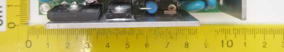


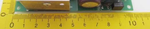
139 age 139 of 160 Report No. T /13

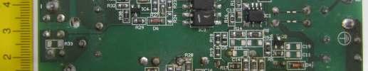
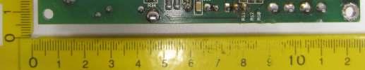
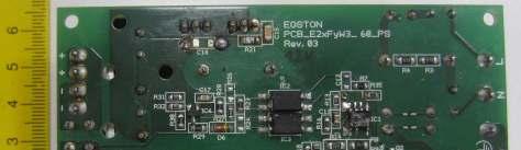
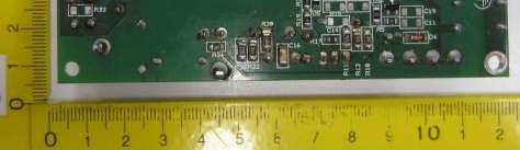
140 age 140 of 160 Report No. T /13

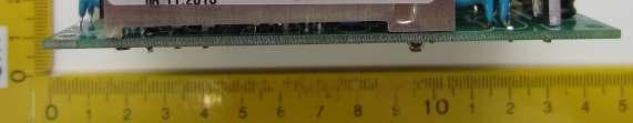

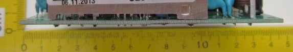
141 age 141 of 160 Report No. T /13
TEST REPORT IEC Audio, video and similar electronic apparatus - Safety requirements
 Test Report issued under the responsibility of www.nemko.com TEST REPORT IEC 60065 Audio, video and similar electronic apparatus - Safety requirements Report Number... : 246847 Date of issue... : October
TEST REPORT IEC Information technology equipment Safety Part 1: General requirements
 Test Report issued under the responsibility of: TEST REPORT IEC 60950-1 Information technology equipment Safety Part 1: General requirements Report Number.... : 210282-CI3-2 CB DE1-56459 Date of issue...
page 2 of 86 Report reference No:
 articulars: test item vs. test requirements 3. Classification 3.1. Utilization category: (A or B)... : A 3.2. Interruption medium: (air, vacuum, gas Break)... : Air 3.3. Design: (open construction, moulded
TEST REPORT IEC : 2005 (2nd Edition) and/or EN :2006 Information technology equipment Safety Part 1: General requirements
 and/or EN :2006 Information technology equipment Safety Part 1: General requirements") Test Report issued under the responsibility of: TEST REPORT IEC 60950-1: 2005 (2nd Edition) and/or EN 60950-1:2006 Information technology equipment Safety Part 1: General requirements Report Reference
Test Report issued under the responsibility of: TEST REPORT IEC 60950-1: 2005 (2nd Edition) and/or EN 60950-1:2006 Information technology equipment Safety Part 1: General requirements Report Reference
SAUDI STANDARD NO. SASO IEC : 2007 SWITCHES FOR HOUSEHOLD AND SIMILAR FIXED ELECTRICAL INSTALLATIONS
 SAUDI STANDARD NO. SASO IEC 60669-2-2: 2007 SWITCHES FOR HOUSEHOLD AND SIMILAR FIXED ELECTRICAL INSTALLATIONS Part 2-2: Particular requirements Electromagnetic remote-control switches (RCS) SAUDI ARABIAN
TEST REPORT IEC Information technology equipment Safety Part 1: General requirements
 Test Report issued under the responsibility of: TEST REPORT IEC 60950-1 Information technology equipment Safety Part 1: General requirements Report Number.... : 207721-AS3-1 CB/DE1-55140 Date of issue...
Amendment to Test Report
 Test Report issued under the responsibility of www.nemko.com Amendment to Test Report This Amendment is valid only together with the main Test Report Report No.... : 270292 Main Report No.... : 261294
TEST REPORT IEC Information technology equipment Safety Part 1: General requirements
 Test Report issued under the responsibility of www.nemko.com TEST REPORT IEC 60950-1 Information technology equipment Safety Part 1: General requirements Report Number....: 285573 Date of issue...: 2015-09-15
HAND-HELD MULTIMETERS
 Test Report issued under the responsibility of: TEST REORT IEC 61010-1, and IEC 61010-2-033 Safety requirements for electrical equipment for measurement, control, and laboratory use. art 1: General requirements,
CB Testing Laboratory...:EZÚ Address...:Pod Lisem Praha71-Trója Testing location/ procedure...: CBTL RMT SMT WMT TMP IEC60947_2C
 age 1 of 109 Report No.600332-04/01 TEST REORT Low-voltage switchgear and controlgear art 2: Circuit - breakers Report Reference No....: 600332-04/01 Tested by (name+signature)...:... Witnessed by (name+signature)...:...
INSTITUTE OF TESTING AND CERTIFICATION (INDIA) PVT. LTD.
 PVT. LTD.") (INDIA) VT. LTD. Clause Requirement Test Results Remarks Verdict 5 Marking and documentation 5.1 Marking 5.1.1 General Markings shall be visible from the exterior, or be visible after removing a cover
(INDIA) VT. LTD. Clause Requirement Test Results Remarks Verdict 5 Marking and documentation 5.1 Marking 5.1.1 General Markings shall be visible from the exterior, or be visible after removing a cover
TEST REPORT IEC Information technology equipment Safety Part 1: General requirements
 Test Report issued under the responsibility of: TEST REPORT IEC 60950-1 Information technology equipment Safety Part 1: General requirements Report Number.... : 212475-CI3-1 CBDE1-52299/A1/M1 Date of issue...
TEST REPORT IEC , IEC
 Test Report issued under the responsibility of: TEST REORT IEC 61010-1, IEC 61010-2-032 and IEC 61010-2-033 Safety requirements for electrical equipment for measurement, control, and laboratory use. art
TEST REPORT IEC Information technology equipment Safety Part 1: General requirements
 Test Report issued under the responsibility of: TEST REPORT IEC 60950-1 Information technology equipment Safety Part 1: General requirements Report Number....: T223-0102/16 Date of issue...: 2016-03-15
Test Report. The safety testing has been performed on the submitted samples and found in compliance with the council LVD directive 2006/95/EC.
 Test Report Applicant: GUANGDONG EAST OWER CO., LTD roduct: FULLY AUTOMATIC AC VOLTAGE REGULATOR Brand Name: EAST Model No: ZTY-20KVA, ZTY-10KVA, ZTY-15KVA repared by: Most Technology Service Co., Limited
Test Report THREE PHASE FULLY AUTOMATIC AC VOLTAGE REGULATOR
 Test Report Applicant: GUANGDONG EAST OWER CO., LTD roduct: THREE HASE FULLY AUTOMATIC AC VOLTAGE REGULATOR Brand Name: EAST Model No: ZTY-30KVA repared by: Most Technology Service Co., Limited The safety
TEST REPORT IEC Information technology equipment Safety Part 1: General requirements
 Test Report issued under the responsibility of: TEST REPORT IEC 60950-1 Information technology equipment Safety Part 1: General requirements Report Number....: T223-0104/16 Date of issue...: 2016-03-15
Page 2 of 69 VDE Report No.: / DC - DC Converter for building in. TDK Innoveta Inc. iba - Series (see model matrix appendix 1)
") Page 2 of 69 VDE Report No.: 2520400-3336-0009/132550 Test item description... : Trade Mark...: Manufacturer...: Model/Type reference...: Serial Number..: Ratings...: Input: Output: Ambient: DC - DC Converter
Page 2 of 69 VDE Report No.: 2520400-3336-0009/132550 Test item description... : Trade Mark...: Manufacturer...: Model/Type reference...: Serial Number..: Ratings...: Input: Output: Ambient: DC - DC Converter
TEST REPORT IEC Adjustable speed electrical power drive systems Part 5-1: Safety requirements Electrical, thermal and energy
 Test Report issued under the responsibility of: TEST REPORT Adjustable speed electrical power drive systems Part 5-1: Safety requirements Electrical, thermal and energy Report Reference No.... : 4787846262
TEST REPORT IEC Information technology equipment Safety Part 1: General requirements
 Test Report issued under the responsibility of: TEST REPORT IEC 60950-1 Information technology equipment Safety Part 1: General requirements Report Number....: T223-0042/16 Date of issue...: 2016-03-04
TEST REPORT. Building 24 (floors1,3,4,5) and 28 (floors1-4) Central Science and Technology Park, Shennan Rd, Nanshan, Shenzhen, China Standards used:
 and 28 (floors1-4) Central Science and Technology Park, Shennan Rd, Nanshan, Shenzhen, China Standards used:") TEST REPORT To: Address: TP-LINK TECHNOLOGIES CO., LTD. Building 24 (floors1,3,4,5) and 28 (floors1-4) Central Science and Technology Park, Shennan Rd, Nanshan, Shenzhen, China Factory name: TP-LINK TECHNOLOGIES
TEST REPORT To: Address: TP-LINK TECHNOLOGIES CO., LTD. Building 24 (floors1,3,4,5) and 28 (floors1-4) Central Science and Technology Park, Shennan Rd, Nanshan, Shenzhen, China Factory name: TP-LINK TECHNOLOGIES
TEST REPORT IEC Low-voltage switchgear and controlgear - Part 2: Circuit-breakers
 Test Report issued under the responsibility of: TEST REORT Low-voltage switchgear and controlgear - art 2: Circuit-breakers Report Reference No.... : 3305316.50 Date of issue... : 2013-09-17 Total number
TEST REPORT IEC Information technology equipment Safety Part 1: General requirements
 Test Report issued under the responsibility of: TEST REORT IEC 60950-1 Information technology equipment Safety art 1: General requirements Report Number.... : T221-0052/16 Date of issue... : 2016-07-14
TEST REPORT IEC Part 2: Particular requirements Section Thirteen d.c. or a.c. supplied electronic controlgear for LED modules
 age 1 of 32 Test Report issued under the responsibility of: Intertek Testing Services Shenzhen Ltd. Guangzhou Branch TEST REORT art 2: articular requirements Section Thirteen d.c. or a.c. supplied electronic
TEST REPORT IEC Part 2: Particular requirements Section Thirteen d.c. or a.c. supplied electronic controlgear for LED modules
 age 1 of 31 Test Report issued under the responsibility of: Intertek Testing Services Shenzhen Ltd. Guangzhou Branch TEST REORT art 2: articular requirements Section Thirteen d.c. or a.c. supplied electronic
USER'S MANUAL DMR-6700
 USER'S MANUAL Multimeter True RMS DMR-6700 CIRCUIT-TEST ELECTRONICS www.circuittest.com Introduction This meter measures AC/DC Voltage, AC/DC Current, Resistance, Capacitance, Frequency (electrical & electronic),
TEST REPORT IEC Safety of Transportable Motor-Operated Power Tools
 Test Report issued under the responsibility of: STAYER IBÉRICA S.A TEST REPORT Safety of Transportable Motor-Operated Power Tools REPORT IDS TR_POTENZA160_SEG_01 Report Reference No. : TR_POTENZA160_SEG_01
IfYcSXY]W!F^fUa!Id [h! IUU!FQWU!,! IB!FEM;H!;B;8JHED?8I!
![IfYcSXY]W!F^fUa!Id [h! IUU!FQWU!,! IB!FEM;H!;B;8JHED?8I!](/thumbs/80/81643598.jpg "IfYcSXY]W!F^fUa!Id [h! IUU!FQWU!,! IB!FEM;H!;B;8JHED?8I!") ! +), HUV(!8UacYV(!D^(.2$(**)$93?;8!IOIJ;C!
! +), HUV(!8UacYV(!D^(.2$(**)$93?;8!IOIJ;C!
DE Total. American Inc. IEC Test Report Form. If this. and appended to General disclaimer: the NCB, VDE File. No VDE File.
 1Fdar Test Report issued under the responsibility of: TEST REPORT IEC 60950-1 Information technology equipment Safety Part 1: General requirements Report Number....: 215009-CI3-1 Date of issue...: 2015-07-31
TEST REPORT DIN V VDE V :2006 Automatic disconnecting device
 age 1 of 23 TEST REORT Automatic disconnecting device Report Reference No...: GZ10080033-1 Date of issue...: August 18, 2010 Total number of pages... 23 pages Testing Laboratory...: Address...: Tested
TEST REPORT IEC Electromagnetic Compatibility (EMC)
") Test Report issued under the responsibility of: STAYER IBÉRICA S.A TEST REPORT Electromagnetic Compatibility (EMC) REPORT IDS TR_ PLUS_140_EMC_01 Report Reference No. : TR_ PLUS_140_EMC_01 Date of issue...
Test Report issued under the responsibility of: STAYER IBÉRICA S.A TEST REPORT Electromagnetic Compatibility (EMC) REPORT IDS TR_ PLUS_140_EMC_01 Report Reference No. : TR_ PLUS_140_EMC_01 Date of issue...
IfYcSXY]W!F^fUa!Id [h! IUU!FQWU!,! IB!FEM;H!;B;8JHED?8I! 8J<!IcQWU!+!
![IfYcSXY]W!F^fUa!Id [h! IUU!FQWU!,! IB!FEM;H!;B;8JHED?8I! 8J<!IcQWU!+!](/thumbs/80/81390013.jpg "IfYcSXY]W!F^fUa!Id [h! IUU!FQWU!,! IB!FEM;H!;B;8JHED?8I! 8J<!IcQWU!+!") ! +), HUV(!8UacYV(!D^(.2$)*(($93?;8!IOIJ;C!
! +), HUV(!8UacYV(!D^(.2$)*(($93?;8!IOIJ;C!
TEST REPORT IEC Contactors and motor-starters Electromechanical contactors and motor-starters
 Test Report issued under the responsibility of: TEST REORT Contactors and motor-starters Electromechanical contactors and motor-starters Report Number.... : SH11090656-001 Date of issue... : October 19,
TEST REPORT IEC Safety of laser products - Part 1: Equipment classification and requirements
 Test Report issued under the responsibility of: TEST REPORT IEC 60825-1 Safety of laser products - Part 1: Equipment classification and requirements Report Number.... : GZES160801248631 Date of issue...
TEST REPORT IEC Information technology equipment - Safety - Part 1: General requirements
 Issue Date: 2015-07-21 Page 1 of 119 Report Reference # 4786910622-5 Test Report issued under the responsibility of: TEST REPORT IEC 60950-1 Information technology equipment - Safety - Part 1: General
TEST REPORT IEC Part 2: Particular requirements Section Thirteen d.c. or a.c. supplied electronic controlgear for LED modules
 age 1 of 38 Test Report issued under the responsibility of: Intertek Testing Services Shenzhen Ltd. Guangzhou Branch TEST REORT art 2: articular requirements Section Thirteen d.c. or a.c. supplied electronic
TEST REPORT. IEC DC or AC supplied electronic control gear for LED modules Performance requirements
 Test Report issued under the responsibility of: UL International Italia S.r.l. TEST REPORT IEC 62384 DC or AC supplied electronic control gear for LED modules Performance requirements Report Reference
120/240 Watt AC-DC Front End with PFC W Series Convert Select 120 Convert Select 240
 Industrial Environment AC-DC Converters >100 Watt W Series 120/240 Watt AC-DC Front End with PFC W Series Convert Select 120 Convert Select 240 Rugged 35 mm DIN-rail snap-fit design 3000 V AC input to
AC/DC Clamp Meter. Owner's Manual. Model No Safety Operation Maintenance Español
 Owner's Manual AC/DC Clamp Meter Model No. 82369 CAUTION: Read, understand and follow Safety Rules and Operating Instructions in this manual before using this product. Safety Operation Maintenance Español
IDEAL INDUSTRIES, INC. TECHNICAL MANUAL MODEL: MODEL: Multimeter Service Information
 IDEAL INDUSTRIES, INC. TECHNICAL MANUAL MODEL: 61-340 MODEL: 61-342 Multimeter Service Information The Service Information provides the following information: Precautions and safety information Specifications
TEST REPORT IEC Safety requirements for electrical equipment for measurement, control, and laboratory use Part 1: General requirements
 Page 2 of 85 Report No. 222/7112462/2 of 2 TEST REPORT IEC 61010-1 Safety requirements for electrical equipment for measurement, control, and laboratory use Part 1: General requirements Report Reference
10/2 Product overview. 10/3 4AC3 0, 4AC3 1 bell transformers. 10/5 4AC AC3 6 transformers for permanent loads. 10/8 4AC2 4 power supply units
 BETA Switching Transformers, Bells and Socket Outlets /2 Product overview /3 4AC3 0, 4AC3 1 bell transformers /5 4AC3 4... 4AC3 transformers for permanent loads /8 4AC2 4 power supply units / 7LQ2 2 bells
Prepared by Mick Maytum
 IEC Technical Committee 109: Standards on insulation co-ordination for low-voltage equipment Warning Prepared by Mick Maytum mjmaytum@gmail.com The document content is of a general nature only and is not
DM-45 Digital Multimeter
 INSTRUCTION MANUAL DM-45 Digital Multimeter Read and understand all of the instructions and safety information in this manual before operating or servicing this tool. Description The Greenlee DM-45 Digital
DIGITAL MULTIMETER CONTENTS DIGITAL MULTIMETER CONTENTS
 CONTENTS CONTENTS CONTENTS 1. SAFETY INFORMATION...1 1.1 Preliminary...1 1.2 Dos and don ts...2 1.3 Symbols...3 1.4 Precautions...4 2. DESCRIPTION...5 2.1 Names of parts...6 2.2 Switches, buttons and input
TEST REPORT IEC60950_1F. Information technology equipment - Safety - Part 1: General requirements
 Issue Date: 2017-05-23 Page 1 of 9 Report Reference # 4787989179 Test Report issued under the responsibility of: TEST REPORT IEC 60950-1 Information technology equipment - Safety - Part 1: General requirements
USER MANUAL 600A AC Clamp Meter + NCV Model MA610
 USER MANUAL 600A AC Clamp Meter + NCV Model MA610 Additional User Manual Translations available at www.extech.com Introduction Thank you for selecting the Extech MA610 Clamp Meter. This meter measures
Standard ECMA-287 Technical Report EACEM TR-027
 EACEM Safety of electronic equipment Standard ECMA-287 Technical Report EACEM TR-027 ECMA Standardizing Information and Communication Systems Phone: +41 22 849.60.00 - Fax: +41 22 849.60.01 - www.ecma.ch
PEN TYPE DIGITAL MULTIMETER OPERATION MANUAL T8211D
 PEN TYPE DIGITAL MULTIMETER OPERATION MANUAL T8211D T8211D 1 1. SAFETY INFORMATION BE EXTREMELY CAREFUL IN THE USE OF THIS METER. Improper use of this device can result in electric shock or destroy of
IGS IGS-M-EL-22(1) Contactors APPROVED. Iranian Gas Standards
 Contactors APPROVED. Iranian Gas Standards") APPROVED IGS Iranian Gas Standards Contactors. Fax:(9821)-8131-5679 --. /012 34-52673892 :;395- 8? /@A7 B;CD /E FGH 34-52673892I2
APPROVED IGS Iranian Gas Standards Contactors. Fax:(9821)-8131-5679 --. /012 34-52673892 :;395- 8? /@A7 B;CD /E FGH 34-52673892I2
Power supply CP-E 24/2.5
 2CDC 271 015 F0t06 a OUTPUT L+, L : terminals output b DC OK: terminal signalling output c INPUT L, N, PE: terminals input d OUTPUT OK: green LED output voltage OK e OUTPUT Adjust: potentiometer adjustment
returned to your distributor for attention. 14. Do not operate the function switch while the instrument is connected to a circuit.
 1. This instrument must only be used by a competent and trained person and operated in strict accordance with the instructions. KYORITSU will not accept liability for any damage or injury caused by misuse
Power supply CP-E 24/20.0
 2CDC 271 027 F0008 a OUTPUT L+, L+, L, L-: terminals output b INPUT L, N, PE: terminals input c 13-14: terminals - signalling contact d OUTPUT OK: green LED output voltage OK e OUTPUT LOW: red LED output
INSTRUCTION MANUAL DIGITAL PSC-LOOP TESTER MODEL 4118A KYORITSU ELECTRICAL INSTRUMENTS WORKS,LTD.
 INSTRUCTION MANUAL DIGITAL PSC-LOOP TESTER MODEL 4118A KYORITSU ELECTRICAL INSTRUMENTS WORKS,LTD. CONTENTS 1. SAFE TESTING... 1 2. PROCEDURE OF REMOVING COVER... 4 3. FEATURES... 5 3.1 Instrument Layout...
TEST REPORT. Date: September 27, 2016 Date: September 27, 2016
 TEST REORT To: Address: T-LINK TECHNOLOGIES CO., LTD. Building 24 (floors1,3,4,5) and 28 (floors1-4) Central Science and Technology ark, Shennan Rd, Nanshan, Shenzhen, China Factory name: T-LINK TECHNOLOGIES
IDEAL INDUSTRIES, INC. TECHNICAL MANUAL MODEL:
 IDEAL INDUSTRIES, INC. TECHNICAL MANUAL MODEL: 61-352 The Service Information provides the following information: Precautions and safety information Specifications Basic maintenance (cleaning, replacing
Power supply CP-D 24/4.2 Primary switch mode power supply
 Data sheet Power supply CP-D 24/4.2 Primary switch mode power supply The CP-D range of modular power supply units in MDRC design (modular DIN rail components) is ideally suited for installation in distribution
TEST REPORT IEC Information technology equipment - Safety - Part 1: General requirements
 Issue Date: 2015-10-19 Page 1 of 143 Report Reference # 4786910627-9 Test Report issued under the responsibility of: TEST REPORT IEC 60950-1 Information technology equipment - Safety - Part 1: General
AMM-1022 Digital Multimeter USER`S MANUAL
 Digital Multimeter USER`S MANUAL www.tmatlantic.com CONTENTS 1. SAFETY INFORMATION.3 2. DESCRIPTION..6 3. SPECIFICATIONS.8 4. OPERATING INSTRUCTION..11 4.1 Voltage measurement...11 4.2 Current measurement
TEST REPORT IEC Part 5: Control circuit devices and switching elements Electromechanical control circuit devices
 Test Report issued under the responsibility of: TEST REORT art 5: Control circuit devices and switching elements Electromechanical control circuit devices Report Number.... : 131000403SHA-003 Date of issue...
Compact Autoranging Clamp Meters. Models (400 A AC), (400 A AC/DC)
, (400 A AC/DC)") User Manual Compact Autoranging Clamp Meters with NIST-Traceable Calibration Models 20250-55 (400 A AC), 20250-56 (400 A AC/DC) THE STANDARD IN PRECISION MEASUREMENT 1065DGMAN_20250-55,-56 DS Clamp Meter
User Manual Compact Autoranging Clamp Meters with NIST-Traceable Calibration Models 20250-55 (400 A AC), 20250-56 (400 A AC/DC) THE STANDARD IN PRECISION MEASUREMENT 1065DGMAN_20250-55,-56 DS Clamp Meter
TEST REPORT IEC Information technology equipment - Safety - Part 1: General requirements
 Issue Date: 2015-02-26 Page 1 of 61 Report Reference # E122103-A161-CB-1 Test Report issued under the responsibility of: Report Reference No... : TEST REPORT IEC 60950-1 Information technology equipment
3B SCIENTIFIC PHYSICS
 3B SCIENTIFIC PHYSICS Analogue Multimeter Escola 100 1013527 Instruction sheet 12/15 SD/JS 1 Display with mirror scale 2 Slotted screw for zero calibration 3 Calibration trimmer for setting centre zero
400Amp True RMS AC Clamp Meter + NCV
 User Guide 400Amp True RMS AC Clamp Meter + NCV Model MA410T Introduction Thank you for selecting the Extech MA410 Clamp Meter. This meter measures AC Current, AC/DC Voltage, Resistance, Capacitance, Frequency,
MINI-PS AC/24DC/1.3
 Power supply unit INTERFACE Data sheet 102894_en_03 1 Description PHOENIX CONTACT 2015-11-17 Features MINI POWER power supplies for MCR technology In measurement and control technology (MCR), modular electronics
AC/DC DIGITAL CLAMP METER OPERATION MANUAL
 AC/DC DIGITAL CLAMP METER OPERATION MANUAL HYS005661 A0 ACCESSORIES 6. ACCESSORIES 1) Test Leads: Electric Ratings 1000V 10A 1 pair (set) 2) Operating Manual 1 copy 3) 1.5V AAA Battery 3 piece - - 55 -
TEST REPORT IEC Information technology equipment - Safety - Part 1: General requirements
 Issue Date: 2015-08-10 Page 1 of 27 Report Reference # E122103-A152-CB-2 Test Report issued under the responsibility of: Report Reference No... : TEST REPORT IEC 60950-1 Information technology equipment
Overtravel of 3.5 mm max. Power source DC D5C-1DS0 D5C-1DP0 D5C-1DA0 AC D5C-1AS0 D5C-1AP0 D5C-1AA0 Antenna only D5C-00S0 D5C-00P0 D5C-00A0
 Touch Switch Unique 18 mm Capacitive Touch Switch with Choice of Three Actuators is Activated with Only a Very Slight Physical Contact Lightweight objects, such as thin wire or foil can be accurately detected.
TEST REPORT IEC Uninterruptible power systems Part 3: Method of specifying the performance and test requirements
 Test Report issued under the responsibility of: TEST REORT IEC 62040-3 Uninterruptible power systems art 3: Method of specifying the performance and test requirements Report reference No...: 11-EL-0026.06
OPERATOR S INSTRUCTION MANUAL M-2625 AUTO RANGING DIGITAL MULTIMETER
 OPERATOR S INSTRUCTION MANUAL M-2625 AUTO RANGING DIGITAL MULTIMETER with Temperature Probe Copyright 2007 Elenco Electronics, Inc. Contents 1. Safety Information 3,4 2. Safety Symbols 5 3. Front Plate
EASQ ELECTRICAL APPLIANCE SERVICEPERSON (QUALIFIED) MARKING SCHEDULE. SECTION 1 Marks Reference Marking notes Qu 1 A 10 MΩ (2 marks)
 MARKING SCHEDULE. SECTION 1 Marks Reference Marking notes Qu 1 A 10 MΩ (2 marks)") EASQ ELECTRICAL APPLIANCE SERVICEPERSON (QUALIFIED) MARKING SCHEDULE Notes: 1. (1mark) means that the preceding statement/answer earns 1 mark. 2. This schedule sets out the expected answers to the examination
EASQ ELECTRICAL APPLIANCE SERVICEPERSON (QUALIFIED) MARKING SCHEDULE Notes: 1. (1mark) means that the preceding statement/answer earns 1 mark. 2. This schedule sets out the expected answers to the examination
TEST REPORT IEC Audio, video and similar electronic apparatus - Safety requirements
 Test Report issued under the responsibility of: TEST REORT IEC 60065 Audio, video and similar electronic apparatus - Safety requirements Report Number.... : 17706907 001 Date of issue... : See cover page
UL International Demko A/S
 Issue Date: 2010-12-01 Page 1 of 56 Report Reference # E252373-A31-CB-1 Test Report issued under the responsibility of: Report Reference No... : TEST REPORT IEC 60950-1 Information technology equipment
Power supply CP-D 24/1.3
 2CDC 271 027 F0t07 a OUTPUT ++/ : terminals output Features Rated output voltage 24 V DC Output voltage adjustable via front face potentiometer OUTPUT Adjust Rated output current 1.3 A Rated output power
200Amp AC Clamp Meter + NCV Model MA250
 User's Guide 200Amp AC Clamp Meter + NCV Model MA250 Introduction Congratulations on your purchase of this Extech MA250 Clamp Meter. This meter measures AC Current, AC/DC Voltage, Resistance, Capacitance,
Power supply CP-D 12/2.1
 2CDC 271 025 F0t07 a OUTPUT ++/ : terminals output Features Rated output voltage 12 V DC Output voltage adjustable via front face potentiometer OUTPUT Adjust Rated output current 2.1 A Rated output power
ADC5000 SERIES. AC/DC Switch Mode Power Supplies and Rectifiers for Industrial and Telecom Applications. 60W, 125W and 250 W
 ADC5000 SERIES AC/DC Switch Mode Power Supplies and Rectifiers for Industrial and Telecom Applications 60W, 125W and 250 W Input voltage 230/115 VAC voltages 12, 24, 36 or 48 VDC Statistical MTBF >3 000
Power supply CP-E 48/5.0 Primary switch mode power supply Data sheet
 2CDC 271 028 F0008 OUTPUT L+, L+, L-, L-: terminals - output Features Rated output voltage 48 V DC Output voltage adjustable via front-face rotary potentiometer OUTPUT Adjust Rated output current 5 A Rated
TEST REPORT. Reference No.:A Report No.:LVDA Page:2 of 34 Date:Feb. 20, 2003
 age:2 of 34 Type of test object... : Wireless 11b Card Bus Trademark... : MSI Model and/or type reference... : MS-6802 Manufacturer... : MICRO-STAR IT L CO., LTD. Rating(s)... : DC 3.3V, 400 ma articulars:
SUGGESTED SPECIFICATION for Series 300 Automatic Transfer Switches
 SUGGESTED SPECIFICATION for Series 300 Automatic Transfer Switches PART 1 GENERAL 1.01 Scope Furnish and install automatic transfer switches (ATS) with number of poles, amperage, voltage, and withstand
3B SCIENTIFIC PHYSICS
 3B SCIENTIFIC PHYSICS Digital Multimeter E 1018832 Instruction sheet 12/16 SD/UD 1 probe 1a Finger guards 2 Measurement socket 10 A for current measurement in 10-A (positive) 3 Measurement socket COM (negative)
Power supply CP-E 24/0.75
 2CDC 271 016 F0t06 a OUTPUT L+, L : terminals output b INPUT L, N, PE: terminals input c LOW: red LED output voltage too low d OK: green LED output voltage OK e OUTPUT Adjust: rotary potentiometer output
Power supply CP-T 48/20.0 Primary switch mode power supply
 Data sheet Power supply CP-T 48/20.0 Primary switch mode power supply The CP-T range of three-phase power supply units is the youngest member of ABB s power supply family. In terms of design and functionality,
MINI-PS AC/2X15DC/1
 MII-PS-100-240AC/2X15DC/1 Power supply unit ITERFACE Data sheet 100299_en_04 1 Description PHOEIX COTACT - 2010-10-20 Features MII POWER is the extremely slim power supply unit with constructional widths
Analogue Demo Multimeter ADM
 Analogue Demo Multimeter ADM 2 3820-0 PHYWE Systeme GmbH & Co. KG Robert-Bosch-Breite 0 D-37079 Göttingen Telefon +49 (0) 55 604-0 Fax +49 (0) 55 604-07 E-mail info@phywe.de Operating instructions The
TEST REPORT IEC Information technology equipment - Safety - Part 1: General requirements
 Issue Date: 2015-06-25 Page 1 of 78 Report Reference # E122103-A133-CB-2 Test Report issued under the responsibility of: Report Reference No... : TEST REPORT IEC 60950-1 Information technology equipment
Keysight U1461A Insulation Multimeter/ U1453A Insulation Tester
 Keysight U46A Insulation Multimeter/ U453A Insulation Tester Quick Start Guide Standard Accessories Included In Your Purchase Standard Accessories Included In Your Purchase The following accessories are
SOLARLOK PV BAR Junction Box
 SOLARLOK PV BAR Junction Box Table of contents 1. SCOPE... 2 1.1. Content... 2 1.2. Qualification... 3 2. APPLICABLE DOCUMENTS... 3 2.1. TE Connectivity Documents... 3 2.2. Commercial Standard... 3 3.
Tube Facing Tool.
 www.swagelok.com Tube Facing Tool This manual contains important information for the safe and effective operation of the Swagelok TF72 series tube facing tool. Users should read and understand its contents
Power supply CP-E 12/10.0 Primary switch mode power supply Data sheet
 2CDC 271 024 F0008 OUTPUT L+, L+, L-, L-: terminals - output INPUT L, N, PE: terminals - input OUTPUT OK: green LED - output voltage OK OUTPUT LOW: red LED - output voltage too low OUTPUT Adjust: potentiometer
User s Manual. MiniTec TM Series. Model MN26 (Model MN26T includes temperature probe) Mini Autoranging MultiMeter
 Mini Autoranging MultiMeter") User s Manual MiniTec TM Series Model MN26 (Model MN26T includes temperature probe) Mini Autoranging MultiMeter Introduction Congratulations on your purchase of Extech s MN26 Autoranging Multimeter. This
User s Manual MiniTec TM Series Model MN26 (Model MN26T includes temperature probe) Mini Autoranging MultiMeter Introduction Congratulations on your purchase of Extech s MN26 Autoranging Multimeter. This
7. INSPECTION AND TEST PROCEDURES
 7.1 Switchgear and Switchboard Assemblies A. Visual and Mechanical Inspection 1. Compare equipment nameplate data with drawings and specifications. 2. Inspect physical and mechanical condition. 3. Inspect
TEST REPORT IEC Part 1: General requirements for basic safety and essential performance
 Test Report issued under the responsibility of: TEST REORT art 1: General requirements for basic safety and essential performance Report Number.... : T221-0013/17 Date of issue... : 2017-03-31 Total number
FINAL - EST Electrical Service Technician Answer Schedule
 FINAL - EST 2069 - Electrical Service Technician Answer Schedule Notes:1. means that the preceding statement/answer earns 1 mark. 2. This schedule sets out the accepted answers to the examination questions.
Model ST Instruction Manual. True RMS Autoranging Digital Multimeter. reedinstruments. www. com
 Model ST-9933 True RMS Autoranging Digital Multimeter Instruction Manual reedinstruments com Table of Contents Safety... 3 Features... 4 Specifications...4-8 Technical...4-5 Accuracy...5-8 Display Description...
400 MHz Passive High-Voltage Probe R&S RT-ZH
 Manual 400 MHz Passive High-Voltage Probe R&S RT-ZH11 1409.7737.02 Printed in Germany Test and Measurment Manufacturer ROHDE & SCHWARZ For comprehensive information about Rohde and Schwarz, please visit
MS8268 HANDHELD DIGITAL MULTIMETER OPERATOR S INSTRUCTION MANUAL
 MS8268 HANDHELD DIGITAL MULTIMETER OPERATOR S INSTRUCTION MANUAL Table of Contents TITLE PAGE 1. GENERAL INSTRUCTIONS 1 1.1 Precaution safety measures 1 1.1.1 Preliminary 1 1.1.2 During use 2 1.1.3 Symbols
Warning, refer to accompanying documents V CAT II Overvoltage category II device. CSA Canadian Standards Association
 About this Manual To the best of our knowledge and at the time written, the information contained in this document is technically correct and the procedures accurate and adequate to operate this instrument
EM420A/420B DIGITAL MULTIMETER OWNERS MANUAL Read this owners manual thoroughly before use
 http://www.all-sun.com EM420A/420B DIGITAL MULTIMETER OWNERS MANUAL V Read this owners manual thoroughly before use WARRANTY This instrument is warranted to be free from defects in material and workmanship
Autoranging Multimeter Extech EX503
 User's Guide Autoranging Multimeter Extech EX503 Introduction Congratulations on your purchase of the Extech EX503 Autoranging Multimeter. This meter measures AC/DC Voltage, AC/DC Current, Resistance,