Improving the ADF5355 synthesizer board (Version with Touch-Display)
|
|
|
- Patrick Ramsey
- 5 years ago
- Views:
Transcription

1 Improving the ADF5355 synthesizer board (Version with Touch-Display) Hello, Matthias, DD1US, March 24 th 2018, rev 1.1 Searching for a way to extend the frequency range of my test equipment I decided to buy a ready-made kit from Ali Express in China. Introduction: It is a board with the ADF5355 synthesizer IC, which covers the frequency range from 54 MHz to 13.6 GHz, a 125 MHz crystal oscillator and an 32bit ARM based microcontroller STM32F103 RCT6. A second PCB is included which is sandwiched on top and included a resistive color touch display which provides a simple user interface. The price is approximately 110 USD. Here is how is looks and what was included: The board is powered by the mini-usb port or via 5V which need to be supplied to a respective socket next to the mini-usb-port. When I got the board, it powered up properly and at a first glance provided the specified output signals in the full frequency range. 1/27


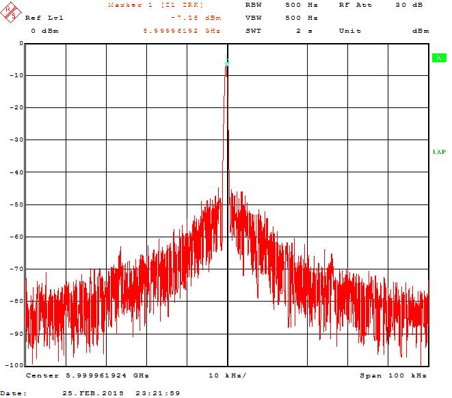
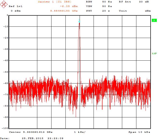
2 First detailed measurements: When checking the signal quality more in detail with a spectrum analyzer, I found that the signal was badly contaminated by noise. Here are 2 screen shots of the poor output signal at 6 GHz. Rechecking the website of the seller I found various spectrum plots but all with a span of 20 MHz which of course do not reveal such a poor signal quality close to the carrier. 2/27


3 Pictures of the board: Here are some pictures of the synthesizer board before doing any modifications: 3/27
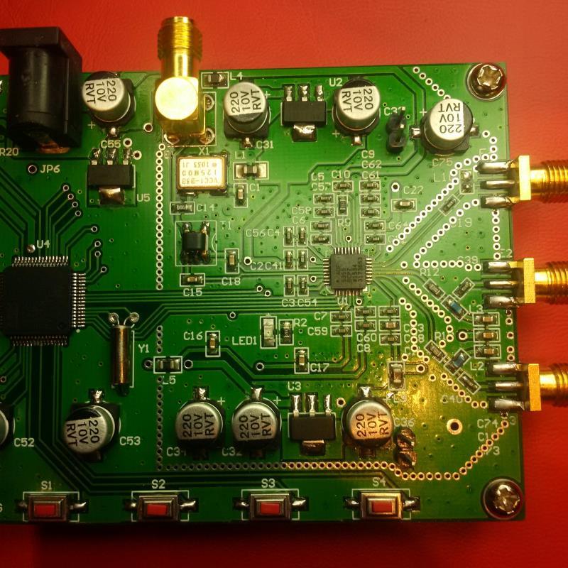
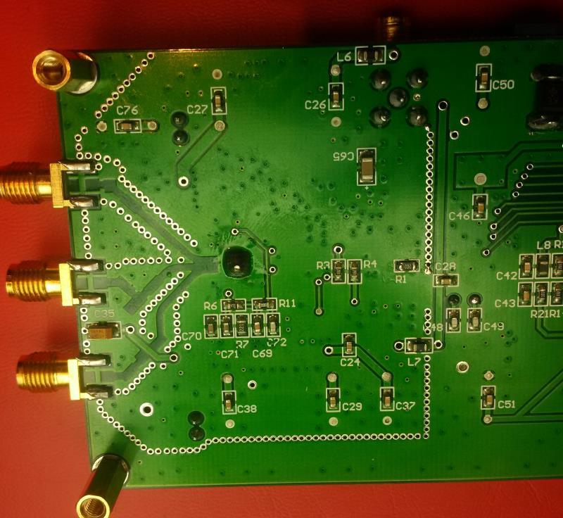
4 4/27


5 Analysis of the PCB: I analyzed the board and was first positively surprised that quite some good RF practice was used in the layout. However, I was shocked when I noticed, that the supply voltage for the VCOs was directly supplied from the external power supply. Only other (less critical blocks) were supplied by some on board regulators. There are some inductors and capacitors for blocking the 5V DC voltage for the VCO but when consulting the datasheet and application notes from Analog Devices it became clear, that special care has to be taking with respect to the power supply for the ADF5355. Even though the synthesizer chip has 4 fully integrated VCO and uses several clever tricks to improve the signal quality, the tuning sensitivity of the VCO is specified with 15 MHz/V. A disturbing signal of 1 mv would thus result in an unwanted modulation of the VCO of 15 khz. Searching the internet, I found an excellent article from Brain Flynn GM8BJF. Here is a link to his website where you can find the article and many more helpful information about synthesizer boards based on the ADF4xxx and ADF5xxx series: Thanks to this information and subsequent frequent exchanges with Brian, I decided to optimize the power supply of my board. Unfortunately, I have a different board compared to the two Brian has been experimenting with. As there is no schematic of my board publicly available I analyzed the board and made my own sketch of the schematic. In order to be able to operate the board and perform measurements on it I had to move the display board aside. I was also suspecting that some of the interference of the RF signal might come from intercoupling between the 2 stacked boards. Thus, I prepared a ribbon cable and separated the boards. 5/27
6 In later investigations it turned out that the display board is not generating additional interference when plugged directly to the synthesizer PCB. Later I received enclosed schematics of the synthesizer board from Reinhard, DL3BR, which I enclose below. 6/27
7 How to improve the performance: I focused especially on the various power supply domains. Besides the 5V supply which is needed for some critical circuitry there are 3 voltage regulators for 3.3V supplies on the board. All are using AMS 1117 regulators. Comparing the output noise performance of various available 5V voltage regulators showed that the respective output RMS noise performance in the frequency range 10Hz to 100 khz varies a lot: A standard L7805CV regulator has for instance 200uV noise, the AMS1117 (5V) is specified with 150uV (from 10Hz to 10kHz), the LT and LT are already much better with 20uV. Looking on the recommended ultra-low noise voltage regulators ADM7150 ACPZ-5.0 showing astonishing 1.6uV. Talking with Brian about this it turned out that he was already preparing a power supply board with 1 piece of ADM7150 ACPZ-5.0 and 2 pieces of ADM7150 ACPZ-3.3 voltage regulators. He was kind enough to provide me a blank PCB and thus I assembled and used this for my purpose. On that board I used the following low ESR 100uF / 6.3V capacitors from Vishay: T55B107M6R3C0035. They feature a ESR of only 35mOhms. The other blocking capacitors are ceramic type. In addition, I needed another 5V supply domain for the touch display board and decided to use a small PCB which I had at hands using an AMS1117. On the synthesizer board also the 3.3V supply for the microcontroller is derived. To reduce the power dissipation in the regulators and provide additional decoupling from the external power supply I added a 9V regulator which powers all following 5V and 3.3V regulators. The nominal external supply voltage range is 12V. The possible supply voltage range is 11V to 20V, limited by the heat dissipation of the 9V regulator which is mounted only on a small heat sink. I assembled the complete power supply comprised of the 2 boards, the primary 9V regulator, reverse supply protection diode and some additional Low ESR capacitors on a carrier board. 7/27
8 Here is a sketch of the schematic of the complete power supply board: On the next page you will find some pictures of the power supply board: 8/27


9 On each output of the power supply board I added a big low ESR 1000uF/6.3V capacitor and I parallel a ceramic 470nF capacitor. 9/27

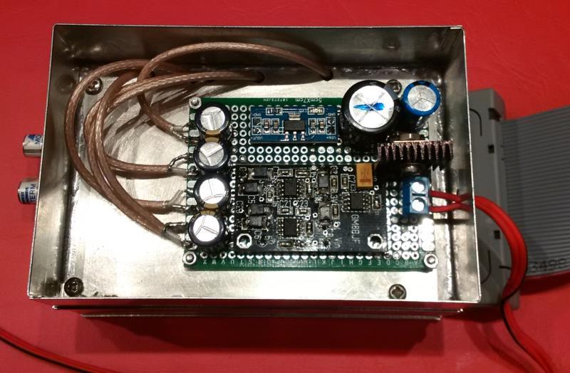
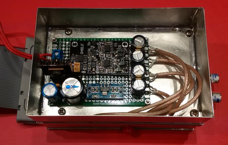
10 In addition, I decided to mount both, the RF synthesizer board and the power supply each in separated tin-plated cabinets to shield them properly from any possibly interferences. Here are pictures of the metal cans which are stacked on each other: Next you can find some pictures with the boards assembled in the metal cases. The power supply connections between the power supply board and the synthesizer board are implemented using thin Teflon based coaxial cables. This shielding should avoid unwanted intercoupling from / to those lines. Before that all voltage regulators except the 3.3V regulator for the microcontroller had been removed from the PCB. In addition, the two inductors marked L4 and L5 were removed to disconnect the VCO supply from the 5V supply of the display board. Finally, I also removed the power supply jack and used the space to add an additional 100uF/6.3V Low- ESR capacitor. 10/27


11 You might have noticed that the color of the round electrolyte capacitors changed. I replaced most of the original capacitors by a 100uF/6.3V type capacitor from PXA with a low ESR of 27mOhms (exact part number is APXA6R3ARA101MF55G). On the backside of the PCB I replaced the Tantal capacitor buffering the power supply for the output stage of the synthesizer with a low ESR 47uF / 6.3V capacitor from Vishay. This T55A476M6R3C0070 features a low ESR of only 70 mohms. 11/27
12 12/27

13 I plan to assembly the synthesizer with the display and additional accessories, such as a ALC (automatic level control) unit and a switchable attenuator, in a nice enclosure. Therefore, I wanted to keep the display separate from the RF board to have optimum flexibility where to place the RF unit relative to the touch-display which has to go into the front panel. I added ferrite RF chokes on each end of the ribbon cable to suppress possible interference in the future setup. Measurement results: On the next pages you will find various measurement results of the modified setup. There are 3 sections with measurements performed on 3 GHz, 6 GHz and 12 GHz. In each section you will first find a wideband spectrum plot showing the harmonics and at the doubler-output also showing the subharmonic. Then you find spectrum plots with the carrier centered and spans of 10 MHz, 1 MHz, 100kHz and 10 khz. Finally, you will find a plot of the measured phase noise. The measurements at 3 GHz and 6 GHz were performed at the output port A+, the measurements at 12 GHz at the doubler-output. Unused RF ports were terminated with a 50 Ohm load. 13/27
14 a) 3 GHz measurements: 14/27
15 15/27


16 The reference line in the last plot s the phase noise of a R&S SME03 signal generator operating at its maximum frequency of 3 GHz. Below 60 khz offset the SME03 is significantly better. 16/27

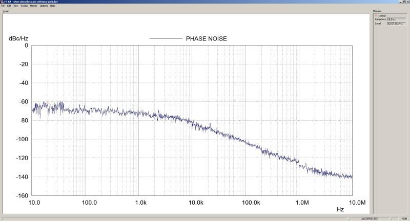
17 b) 6 GHz measurements: 17/27
18 18/27
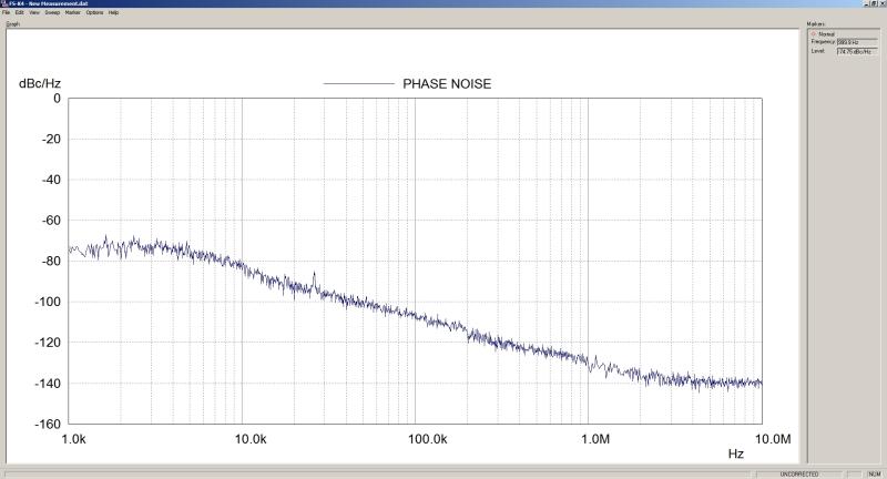
19 19/27

20 c) 12 GHz measurements: 20/27
21 21/27
22 22/27

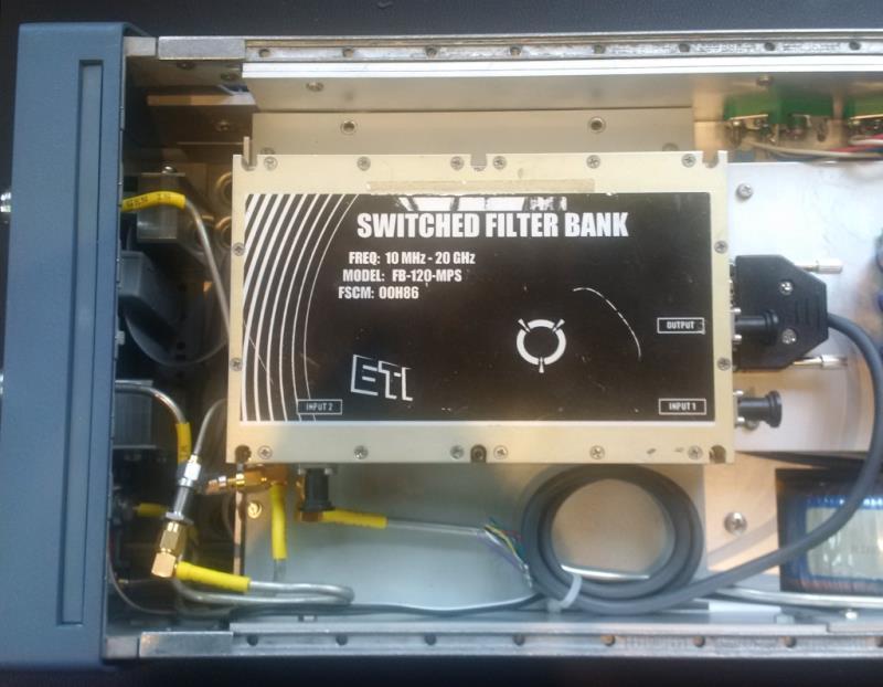
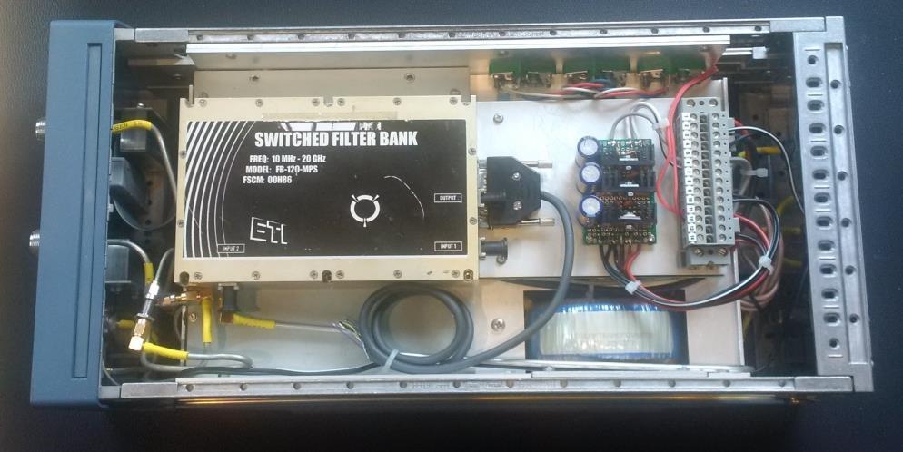
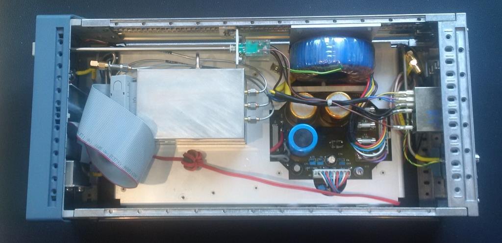
23 Additional notes on other components used on the PCB: The crystal oscillator is a VCC1-B3B-125M00 from Vectron. It provides a single ended 125 MHz output signal. The oscillator operates from a 3.3V supply voltage with a current consumption of max. 50mA. The oscillator can drive loads up to 15 pf. The enable/disable pin is left open and due to the internal pull-up resistor, the oscillator is therefore always running when the supply voltage is applied to the board. It could be disabled if the Enable/Disable pin is connected to ground. The temperature stability of the device is specified with ± 50 ppm in the temperature range from -40 to +70 degree C. The microcontroller STM32F103 RCT6 is based on an 32bit ARM-cortex-M3 core and features 256 kbyte embedded flash and 48 kbyte SRAM memory. It uses a 64 pin LQFP package. Thanks to the flash the code and latest settings can be restored. Thus, the board always starts with the settings like frequency such as it had been used before powering it down. The supply voltage range in this application is 3.3V. The specified temperature range of the microcontroller is -40 to +85 degree C. Adding a nice encasing, mains supply and filter: After optimizing the synthesizer module I decided to integrate it in an old encasing from R&S, which I had bought some years ago. I could reuse the mains power supply in that encasing which delivers +5V, +15V and - 15V. I added a switched filter module FB120-MPS which removes the harmonics when using the outputs A+ and A- respectively the subharmonics when using the output B. As the synthesizer module needs +12V and the filter module needs +12V, -12V and +5V added another voltage regulator board. The filter module is not yet activated as I need some control circuits to switch the various frequency bands. 23/27
24 24/27


25 In order to mount the touch display in the front cover of the encasing a friend designed a 3D printable frame. Many thanks to Edgar, DF2MZ for the kind help. I got the frame printed by They are very nice people and delivered very quickly for a very reasonale price. BTW the color was chosen so it matched the frames of other R&S test equipment I have in the same test equipment rack.here is a sketch and pictures of the frame: 25/27


26 In the next picture you can see the3d printed frame glued into the front-plate. Finally, here are some pictures of the complete unit after integrating the touch-display. 26/27

27 Summary: I now have a very nice synthesizer which I can use to generate signals up to 13 GHz which extends my measurement capabilities. The synthesizer can be used as a fixed frequency source and also for sweeping to measure for instance the frequency response of amplifiers and filters. The phase noise results in the frequency offset range below 10 khz are not on par with the results Brian Flynn had achieved and measured. He reported that optimizing the charge pump output current allowed him to reduce the phase noise in the loop bandwidth. As I do not have access to the source code of the controller board I am not able to perform such optimizations. In the future I hope to get access to a UART-Interface board will try to control the synthesizer by a PC. I will then see, whether I can improve the performance by tweaking internal control registers of the synthesizer. Also, the switched filter module needs to be controlled, preferably also by the UART-Interface. I would like to thank Brian Flynn GM8BJF for his excellent articles, his advice and the PCB for the optimized power supply, Reinhard Beck DL3BR for the schematics of the synthesizer board and Edgar Kaiser DF2MZ for designing the 3D printable frame for the touch-display. I always appreciate feedback. Please send it to the address given below. Many thanks in advance. Best regards Matthias DD1US DD1US@AMSAT.ORG Homepage: 27/27
A low cost signal generator for 54 MHz to 13.4 GHz. Matthias Bopp DD1US
 A low cost signal generator for 54 MHz to 13.4 GHz Matthias Bopp DD1US Microwave & EME Symposium in Gajow / Poland, June 9 th 2018 Agenda Motivation ADF5355 IC Chinese low cost modules Module including
Frequency Doubler 4-8 GHz based on HMC204MS
 Frequency Doubler 4-8 GHz based on HMC204MS Matthias, DD1US, December 2 nd 2018, Rev 2.0 Hello, recently, PCBs with the Hittite HMC204MS passive frequency doubler became available for very low cost on
Frequency Doubler 3,2 6,4 GHz to 6,2 12,8 GHz based on HMC204MS
 Frequency Doubler 3,2 6,4 GHz to 6,2 12,8 GHz based on HMC204MS Matthias, DD1US, January 4 th 2018, Rev 3.0 Hello, as I just finished refurbishing a R&S SMIQ06 signal generator, which covers the frequency
Chinese Microwave Synthesiser PCBs Using ADF4351 and the. Brian Flynn GM8BJF
 Chinese Microwave Synthesiser PCBs Using ADF4351 and the ADF5355 Brian Flynn GM8BJF Overview of Talk Brief review of PLL chips with integrated VCOs. Look at what is readily available. Background on Intand
AN Demonstration of a 1GHz discrete VCO based on the BFR92A. Document information. Keywords Abstract
 Rev. 1.0 26 June 2012 Application note Document information Info Keywords Abstract Content Discrete, VCO, BFR92A, EVB, Design, Evaluation, Measurements This document provides an example of a discrete Voltage
EVALUATION KIT AVAILABLE 10MHz to 1050MHz Integrated RF Oscillator with Buffered Outputs. Typical Operating Circuit. 10nH 1000pF MAX2620 BIAS SUPPLY
 19-1248; Rev 1; 5/98 EVALUATION KIT AVAILABLE 10MHz to 1050MHz Integrated General Description The combines a low-noise oscillator with two output buffers in a low-cost, plastic surface-mount, ultra-small
VCO Design Project ECE218B Winter 2011
 VCO Design Project ECE218B Winter 2011 Report due 2/18/2011 VCO DESIGN GOALS. Design, build, and test a voltage-controlled oscillator (VCO). 1. Design VCO for highest center frequency (< 400 MHz). 2. At
Demo Circuit DC550A Quick Start Guide.
 May 12, 2004 Demo Circuit DC550A. Introduction Demo circuit DC550A demonstrates operation of the LT5514 IC, a DC-850MHz bandwidth open loop transconductance amplifier with high impedance open collector
LBI-30398N. MAINTENANCE MANUAL MHz PHASE LOCK LOOP EXCITER 19D423249G1 & G2 DESCRIPTION TABLE OF CONTENTS. Page. DESCRIPTION...
 MAINTENANCE MANUAL 138-174 MHz PHASE LOCK LOOP EXCITER 19D423249G1 & G2 LBI-30398N TABLE OF CONTENTS DESCRIPTION...Front Cover CIRCUIT ANALYSIS... 1 MODIFICATION INSTRUCTIONS... 4 PARTS LIST AND PRODUCTION
SPECIFICATIONS: Subcarrier Frequency 5.5MHz adjustable, FM Modulated +/- 50KHz. 2nd 11MHz >40dB down from 5.5MHz
 Mini-kits AUDIO / SUBCARRIER KIT EME75 Version4 SPECIFICATIONS: Subcarrier Frequency 5.5MHz adjustable, FM Modulated +/- 50KHz Subcarrier Output 1.5v p-p Output @ 5.5MHz DESCRIPTION & FEATURES: The Notes
ERICSSONZ LBI-30398P. MAINTENANCE MANUAL MHz PHASE LOCKED LOOP EXCITER 19D423249G1 & G2 DESCRIPTION TABLE OF CONTENTS
 MAINTENANCE MANUAL 138-174 MHz PHASE LOCKED LOOP EXCITER 19D423249G1 & G2 TABLE OF CONTENTS Page DESCRIPTION... Front Cover CIRCUIT ANALYSIS...1 MODIFICATION INSTRUCTIONS...4 PARTS LIST...5 PRODUCTION
Glossary of VCO terms
 Glossary of VCO terms VOLTAGE CONTROLLED OSCILLATOR (VCO): This is an oscillator designed so the output frequency can be changed by applying a voltage to its control port or tuning port. FREQUENCY TUNING
10MHz to 1050MHz Integrated RF Oscillator with Buffered Outputs
 9-24; Rev 2; 2/02 EVALUATION KIT AVAILABLE 0MHz to 050MHz Integrated General Description The combines a low-noise oscillator with two output buffers in a low-cost, plastic surface-mount, ultra-small µmax
Package and Pin Assignment SSOP-6 (0.64mm pitch) OSCIN OSCOUT TXEN 3 VSS 4 TXOUT 5 VSS 6 7 MODIN 8 HiMARK SW DO RES RESB VREFP VSS Symbol
 OSCIN OSCOUT TXEN 3 VSS 4 TXOUT 5 VSS 6 7 MODIN 8 HiMARK SW DO RES RESB VREFP VSS Symbol") Low Power ASK Transmitter IC HiMARK Technology, Inc. reserves the right to change the product described in this datasheet. All information contained in this datasheet is subject to change without prior
Low Power ASK Transmitter IC HiMARK Technology, Inc. reserves the right to change the product described in this datasheet. All information contained in this datasheet is subject to change without prior
Features. = +25 C, Vcc = +5V [1]
![Features. = +25 C, Vcc = +5V [1]](/thumbs/80/81652748.jpg "Features. = +25 C, Vcc = +5V [1]") Typical Applications Low Noise wideband MMIC VCO is ideal for: Features Wide Tuning Bandwidth Industrial/Medical Equipment Test & Measurement Equipment Military Radar, EW & ECM Functional Diagram Pout:
Typical Applications Low Noise wideband MMIC VCO is ideal for: Features Wide Tuning Bandwidth Industrial/Medical Equipment Test & Measurement Equipment Military Radar, EW & ECM Functional Diagram Pout:
A precise reference frequency not only for your ham radio station Rev 0.5
 Langenbrettach, April 2nd 2010 Matthias Bopp A precise reference frequency not only for your ham radio station Rev 0.5 A ham radio station needs a stable reference frequency if you want to move to very
ADVANCED EMBEDDED MONITORING SYSTEM FOR ELECTROMAGNETIC RADIATION
 98 Chapter-5 ADVANCED EMBEDDED MONITORING SYSTEM FOR ELECTROMAGNETIC RADIATION 99 CHAPTER-5 Chapter 5: ADVANCED EMBEDDED MONITORING SYSTEM FOR ELECTROMAGNETIC RADIATION S.No Name of the Sub-Title Page
PART MAX2605EUT-T MAX2606EUT-T MAX2607EUT-T MAX2608EUT-T MAX2609EUT-T TOP VIEW IND GND. Maxim Integrated Products 1
 19-1673; Rev 0a; 4/02 EVALUATION KIT MANUAL AVAILABLE 45MHz to 650MHz, Integrated IF General Description The are compact, high-performance intermediate-frequency (IF) voltage-controlled oscillators (VCOs)
The CYF115 transmitter solution is ideal for industrial and consumer applications where simplicity and form factor are important.
 CYF115 Datasheet 300M-450MHz RF Transmitter General Description The CYF115 is a high performance, easy to use, single chip ASK Transmitter IC for remote wireless applications in the 300 to 450MHz frequency
12.92 GHz to GHz MMIC VCO with Half Frequency Output HMC1169
 Data Sheet 12.92 GHz to 14.07 GHz MMIC VCO with Half Frequency Output FEATURES Dual output frequency range fout = 12.92 GHz to 14.07 GHz fout/2 = 6.46 GHz to 7.035 GHz Output power (POUT): 11.5 dbm SSB
PCB Design Guidelines for GPS chipset designs. Section 1. Section 2. Section 3. Section 4. Section 5
 PCB Design Guidelines for GPS chipset designs The main sections of this white paper are laid out follows: Section 1 Introduction Section 2 RF Design Issues Section 3 Sirf Receiver layout guidelines Section
12.17 GHz to GHz MMIC VCO with Half Frequency Output HMC1167
 9 0 3 4 5 6 9 7 6.7 GHz to 3.33 GHz MMIC VCO with Half Frequency Output FEATURES Dual output frequency range fout =.7 GHz to 3.330 GHz fout/ = 6.085 GHz to 6.665 GHz Output power (POUT): 0.5 dbm Single-sideband
Beta-test ED1 PCB installed in I0CG s K1
 K1 SSB Modification (Ed.2) This description provides the receiver (RX) modifications, assembly, alignment and operation as a first step. In a second step you can add the remaining transmitter (TX) modifications,
11.41 GHz to GHz MMIC VCO with Half Frequency Output HMC1166
 9 6 3 30 29 VTUNE 28 27 26.4 GHz to 2.62 GHz MMIC VCO with Half Frequency Output FEATURES Dual output frequency range fout =.4 GHz to 2.62 GHz fout/2 = 5.705 GHz to 6.3 GHz Output power (POUT): dbm Single-sideband
Maxim Integrated Products 1
 19-3533; Rev 0; 1/05 MAX9996 Evaluation Kit General Description The MAX9996 evaluation kit (EV kit) simplifies the evaluation of the MAX9996 UMTS, DCS, and PCS base-station downconversion mixer. It is
The 144MHz Anglian 3 transverter
 The 144MHz Anglian 3 transverter A high performance 144/28MHz transverter G4DDK document issue 1 12/9/16 Introduction Anglian 3 is an update to the 144MHz Anglian 2 transverter. The Anglian 2 is no longer
ALX-SSB 5 Band Filter Assembly Manual 19 November 2018
 ALX-SSB 5 Band Filter Assembly Manual 19 November 2018 Contents Theory of Operation:... 1 Figure 1... 2 Parts Included:... 4 Board Overview:... 5 Figure 2... 5 Figure 3... 5 Board Assembly:... 6 Cable
Features. = +25 C, Vcc = +5V. Parameter Min. Typ. Max. Units Frequency Range GHz Power Output 3 dbm SSB Phase 10 khz Offset -60 dbc/hz
 Typical Applications Low Noise wideband MMIC VCO is ideal for: Industrial/Medical Equipment Test & Measurement Equipment Military Radar, EW & ECM Functional Diagram Features Wide Tuning Bandwidth Pout:
ATV Modulator User Manual
 ATV Modulator User Manual FMTV Modulator by Grant ZL1WTT & Keith ZL1BQE 20 February 2004 Page 1 Display board layout The controller consists of a 2x 16 LCD display with three push buttons and a rotary
10MHz to 500MHz VCO Buffer Amplifiers with Differential Outputs
 19-4797; Rev 0; 2/99 EVALUATION KIT MANUAL FOLLOWS DATA SHEET 10MHz to 500MHz VCO Buffer Amplifiers General Description The / are flexible, low-cost, highreverse-isolation buffer amplifiers for applications
HF Amateur SSB Receiver
 HF Amateur SSB Receiver PCB Set for radio club project http://rhelectronics.net PCB for DIY HF Amateur SSB Receiver 20M The receiver is a simple syperheterodyne type with quartz crystal filter. The circuit
Ocean Controls KT-5198 Dual Bidirectional DC Motor Speed Controller
 Ocean Controls KT-5198 Dual Bidirectional DC Motor Speed Controller Microcontroller Based Controls 2 DC Motors 0-5V Analog, 1-2mS pulse or Serial Inputs for Motor Speed 10KHz, 1.25KHz or 156Hz selectable
HMC6380LC4B. WIDEBAND VCOs - SMT. Electrical Specifications, T A. Typical Applications. Features. General Description. Functional Diagram
 Typical Applications Low Noise wideband MMIC VCO is ideal for: Industrial/Medical Equipment Test & Measurement Equipment Satcom Military Radar, EW, & ECM Functional Diagram Features Wide Tuning Bandwidth
Instruction Manual. SSQ-2F Controller Board. For the. v1.41 For Rife Plasma Tube Systems. Manual v by Ralph Hartwell Spectrotek Services
 Instruction Manual For the SSQ-2F Controller Board v1.41 For Rife Plasma Tube Systems Manual v1.00 2012 by Ralph Hartwell Spectrotek Services This page intentionally blank. 2 Index and Table of Contents
PARAMETER CONDITIONS TYPICAL PERFORMANCE Operating Supply Voltage 3.1V to 3.5V Supply Current V CC = 3.3V, LO applied 152mA
 DESCRIPTION LT5578 Demonstration circuit 1545A-x is a high linearity upconverting mixer featuring the LT5578. The LT 5578 is a high performance upconverting mixer IC optimized for output frequencies in
MTS2500 Synthesizer Pinout and Functions
 MTS2500 Synthesizer Pinout and Functions This document describes the operating features, software interface information and pin-out of the high performance MTS2500 series of frequency synthesizers, from
DEMO CIRCUIT 1004 ADC DRIVER AND 7X7MM HIGH-PERFORMANCE ADC QUICK START GUIDE ADC Driver and 7x7mm High-Performance ADC DESCRIPTION
 DEMO CIRCUIT 1004 QUICK START GUIDE ADC Driver and 7x7mm High-Performance ADC DESCRIPTION Demonstration circuit 1004 is a reference design featuring Linear Technology Corporation s Analog- Digital Converter
AltiumLive 2017: Component selection for EMC
 AltiumLive 2017: Component selection for EMC Martin O Hara Victory Lighting Ltd Munich, 24-25 October 2017 Component Selection Passives resistors, capacitors and inductors Discrete diodes, bipolar transistors,
Wideband Amplifier MITEQ AMF5S P
 Wideband Amplifier MITEQ AMF5S-040080-12-13P Matthias, DD1US, December 2 nd 2018 I am presently building a frequency doubler to extend my measurement setup to higher frequencies. I am using a frequency
Filterless 3W Class- D Mono Audio Amplifier
 Preliminary Datasheet LPA00 Filterless 3W Class- D Mono Audio Amplifier General Description The LPA00 is a 3W, class-d audio amplifier. It offers low THD+N, allowing it to achieve high-quality Power Supply
Clocking the Data ABSTRACT INTRODUCTION KEY WORDS
 Clocking the Data By Jerry Shirar N9XR 6847 Edgebrook Lane Hanover Park, IL 60133 radio.n9xr@gmail.com ABSTRACT Many oscillators attached to the microprocessors and microcontrollers today are simply inverter
HIGH-VALUE PHASE-LOCKED COAXIAL RESONATOR OSCILLATOR
 OSCILLATOR SECTION HIGH-VALUE PHASE-LOCKED COAXIAL RESONATOR OSCILLATOR BCO SERIES: 0.20 4 GHz (Fundamental) 4 16 GHz (Multiplied) FEATURES Low cost Phase locked to external standard or internal crystal
Assembly and Operations Manual Z10000B U Buffer Amplifier
 Assembly and Operations Manual Z10000B U Buffer Amplifier Version 1.02 / 23 November 2009 7236 Clifton Road Clifton Virginia 20124 Telephone: (703) 830 0368 Fax: (703) 830 0711 http://www.cliftonlaboratories.com
SYN113 Datasheet. ( MHz ASK Transmitter) Version 1.0
 Version 1.0") Datasheet (300 450MHz ASK Transmitter) Version 1.0 Contents 1. General Description... 1 2. Features... 1 3. Applications... 1 4. Typical Application... 2 5. Pin Configuration... 2 6. Pin Description...
Datasheet (300 450MHz ASK Transmitter) Version 1.0 Contents 1. General Description... 1 2. Features... 1 3. Applications... 1 4. Typical Application... 2 5. Pin Configuration... 2 6. Pin Description...
Features. = +25 C, Vcc = +5V
 Typical Applications Low noise wideband MMIC VCO for applications such as: Industrial/Medical Equipment Test & Measurement Equipment Military Radar, EW & ECM Functional Diagram Features Wide Tuning Bandwidth
UHF RFID Micro Reader Reference Design Hardware Description
 Application Micro Note Reader Reference Design AS399x UHF RFID Reader ICs UHF RFID Micro Reader Reference Design Hardware Description Top View RF Part Bottom View RF Part www.austriamicrosystems.com/rfid
Military End-Use. Phased Array Applications. FMCW Radar Systems
 Features RF Bandwidth: 9.05 ghz to 10.15 ghz Fractional or Integer Modes Ultra Low Phase Noise 9.6 ghz; 50 MHz Ref. -106 / -102 dbc/hz @ 10 khz (Int / frac) dbc/hz @ 1 MHZ (Open Loop) Figure of Merit (FOM)
High Speed Clock Distribution Design Techniques for CDC 509/516/2509/2510/2516
 High Speed Clock Distribution Design Techniques for CDC 509/516/2509/2510/2516 APPLICATION REPORT: SLMA003A Boyd Barrie Bus Solutions Mixed Signals DSP Solutions September 1998 IMPORTANT NOTICE Texas Instruments
Analog Devices Welcomes Hittite Microwave Corporation NO CONTENT ON THE ATTACHED DOCUMENT HAS CHANGED
 Analog Devices Welcomes Hittite Microwave Corporation NO CONTENT ON THE ATTACHED DOCUMENT HAS CHANGED www.analog.com www.hittite.com THIS PAGE INTENTIONALLY LEFT BLANK Features RF Bandwidth: 9.05 GHz to
ISM Band FSK Receiver IC ADF7902
 ISM Band FSK Receiver IC FEATURES Single-chip, low power UHF receiver Companion receiver to ADF7901 transmitter Frequency range: 369.5 MHz to 395.9 MHz Eight RF channels selectable with three digital inputs
CMT2300AW Schematic and PCB Layout Design Guideline
 AN141 CMT2300AW Schematic and PCB Layout Design Guideline Introduction This document is the CMT2300AW Application Development Guideline. It will explain how to design and use the CMT2300AW schematic and
The Design and Construction of a DDS based Waveform Generator
 1 The Design and Construction of a DDS based Waveform Generator Darrell Harmon Abstract A direct digital synthesis (DDS) based signal generator was designed and constructed to cover the frequency range
G6ALU 20W FET PA Construction Information
 G6ALU 20W FET PA Construction Information The requirement This amplifier was designed specifically to complement the Pic-A-Star transceiver developed by Peter Rhodes G3XJP. From the band pass filter an
AN4819 Application note
 Application note PCB design guidelines for the BlueNRG-1 device Introduction The BlueNRG1 is a very low power Bluetooth low energy (BLE) single-mode system-on-chip compliant with Bluetooth specification
LM2462 Monolithic Triple 3 ns CRT Driver
 LM2462 Monolithic Triple 3 ns CRT Driver General Description The LM2462 is an integrated high voltage CRT driver circuit designed for use in color monitor applications. The IC contains three high input
EVALUATION KIT AVAILABLE 3.5GHz Downconverter Mixers with Selectable LO Doubler. PART MAX2683EUE MAX2684EUE *Exposed pad TOP VIEW IFOUT+ IFOUT-
 -; Rev ; / EVALUATION KIT AVAILABLE.GHz Downconverter Mixers General Description The MAX/MAX are super-high-performance, low-cost downconverter mixers intended for wireless local loop (WLL) and digital
MARTIN - G8JNJ ECLECTIC AETHER - ADVENTURES WITH AMATEUR RADIO
 MARTIN - G8JNJ ECLECTIC AETHER - ADVENTURES WITH AMATEUR RADIO REDUCING RTL DONGLE INTERNAL SPURII AND NOISE SIGNALS I ve recently bought quite a few RTL DVB-T RTL 2832U / Rafael Micro R820T dongles to
Features. = +25 C, 50 Ohm System, Vcc= 5V
 Typical Applications Prescaler for 1 MHz to 13 GHz PLL Applications: Point-to-Point / Multi-Point Radios VSAT Radios Fiber Optic Test Equipment Space & Military Functional Diagram Features Ultra Low ssb
Fabricate a 2.4-GHz fractional-n synthesizer
 University of Malaya From the SelectedWorks of Professor Mahmoud Moghavvemi Summer June, 2013 Fabricate a 2.4-GHz fractional-n synthesizer H Ameri Mahmoud Moghavvemi, University of Malaya a Attaran Available
Maxim Integrated Products 1
 19-0569; Rev 0; 5/06 MAX2041 Evaluation Kit General Description The MAX2041 evaluation kit (EV kit) simplifies the evaluation of the MAX2041 UMTS, DCS, and PCS base-station up/downconversion mixer. It
Analog Devices Welcomes Hittite Microwave Corporation NO CONTENT ON THE ATTACHED DOCUMENT HAS CHANGED
 Analog Devices Welcomes Hittite Microwave Corporation NO CONTENT ON THE ATTACHED DOCUMENT HAS CHANGED www.analog.com www.hittite.com THIS PAGE INTENTIONALLY LEFT BLANK Typical Applications Low noise wideband
SynthNV - Signal Generator / Power Detector Combo
 SynthNV - Signal Generator / Power Detector Combo The Windfreak SynthNV is a 34.4MHz to 4.4GHz software tunable RF signal generator controlled and powered by a PC running Windows XP, Windows 7, or Android
Super Low Noise Preamplifier
 PR-E 3 Super Low Noise Preamplifier - Datasheet - Features: Outstanding Low Noise (< 1nV/ Hz, 15fA/ Hz, 245 e - rms) Small Size Dual and Single Channel Use Room temperature and cooled operation down to
BassAce - Midi Bass Synthesizer. BassAce Features
 Untitled Document BassAce - Midi Bass Synthesizer The BassAce is a small midi-synth based loosely on the TB303. It can be built many different ways. Depending on how it's configured it can be anything
24-bit Step Size, Resolution 3 Hz typ Exact Frequency Mode Built-in Digital Self Test 40 Lead 6x6 mm SMT Package: 36 mm 2. Phased Array Applications
 Features Tri-band RF Bandwidth: Ultra Low Phase Noise -105 dbc/hz in Band Typ. Figure of Merit (FOM) -227 dbc/hz < 180 fs RMS Jitter 24-bit Step Size, Resolution 3 Hz typ Exact Frequency Mode Built-in
DIY Function Generator XR2206
 DIY Function Generator XR2206 20Hz 100KHz http://radiohobbystore.com Components List: Resistors: R1, R2 1% Metal Film 5K1 R4 1% Metal Film 10K R5 1% Metal Film 3K R10 5% Carbon Film 10R R3, R9 Potentiometer
Features. Future Electronics (
 / ASB Embedding the wireless future.. Low-Cost SAW-stabilized surface mount OOK RF transmitter Typical Applications Remote Keyless Entry (RKE) Remote Lighting Controls On-Site Paging Asset Tracking Wireless
24-bit Step Size, Resolution 3 Hz typ Exact Frequency Mode Built-in Digital Self Test 40 Lead 6x6mm SMT Package: 36mm 2. Phased Array Applications
 FRACTIONAL-N PLL WITH INTEGRATED VCO, 80-80 MHz Features RF Bandwidth: 80 to 80 MHz Ultra Low Phase Noise -110 dbc/hz in Band Typ. Figure of Merit (FOM) -22 dbc < 180 fs RMS Jitter 24-bit Step Size, Resolution
433MHz front-end with the SA601 or SA620
 433MHz front-end with the SA60 or SA620 AN9502 Author: Rob Bouwer ABSTRACT Although designed for GHz, the SA60 and SA620 can also be used in the 433MHz ISM band. The SA60 performs amplification of the
HAMTRONICS TB901 FM EXCITER INSTALLATION, OPERATION, & MAINTENANCE
 HAMTRONICS TB901 FM EXCITER INSTALLATION, OPERATION, & MAINTENANCE GENERAL INFORMATION. The TB901 is a single-channel low power fm transmitter (exciter) designed to provide 300-600 milliwatts continuous
PR-E 3 -SMA. Super Low Noise Preamplifier. - Datasheet -
 PR-E 3 -SMA Super Low Noise Preamplifier - Datasheet - Features: Low Voltage Noise (0.6nV/ Hz, @ 1MHz single channel mode) Low Current Noise (12fA/ Hz @ 10kHz) f = 0.5kHz to 4MHz, A = 250V/V (customizable)
Application Note TH7122 and TH71221 used with Narrow-Band IF Circuit
 1 Why use the TH7122 or TH71221 with a narrow-band IF IC when fully integrated narrow-band transceiver ICs are available 1.1 Frequency Coverage TH7122 or TH71221 13.56 to 960MHz 160 to 916MHz 402-960MHz
Laboratory Exercises for Analog Circuits and Electronics as Hardware Homework with Student Laptop Computer Instrumentation
 Laboratory Exercises for Analog Circuits and Electronics as Hardware Homework with Student Laptop Computer Instrumentation Marion O. Hagler Department of Electrical and Computer Engineering Mississippi
QUICK START GUIDE FOR DEMONSTRATION CIRCUIT 678A 40MHZ TO 900MHZ DIRECT CONVERSION QUADRATURE DEMODULATOR
 DESCRIPTION QUICK START GUIDE FOR DEMONSTRATION CIRCUIT 678A LT5517 Demonstration circuit 678A is a 40MHz to 900MHz Direct Conversion Quadrature Demodulator featuring the LT5517. The LT 5517 is a direct
N3ZI Kits General Coverage Receiver, Assembly & Operations Manual (For Jun 2011 PCB ) Version 3.33, Jan 2012
 Version 3.33, Jan 2012") N3ZI Kits General Coverage Receiver, Assembly & Operations Manual (For Jun 2011 PCB ) Version 3.33, Jan 2012 Thank you for purchasing my general coverage receiver kit. You can use the photo above as a
N3ZI Kits General Coverage Receiver, Assembly & Operations Manual (For Jun 2011 PCB ) Version 3.33, Jan 2012 Thank you for purchasing my general coverage receiver kit. You can use the photo above as a
A COMPACT, AGILE, LOW-PHASE-NOISE FREQUENCY SOURCE WITH AM, FM AND PULSE MODULATION CAPABILITIES
 A COMPACT, AGILE, LOW-PHASE-NOISE FREQUENCY SOURCE WITH AM, FM AND PULSE MODULATION CAPABILITIES Alexander Chenakin Phase Matrix, Inc. 109 Bonaventura Drive San Jose, CA 95134, USA achenakin@phasematrix.com
Rakon Product Proposal
 IT2200A -- SMD Temperature Compensated Crystal Oscillators -- -- Low cost SMD TCXO with voltage control option using an analogue IC for compensation. Frequencies ranging from 10MHz to 52MHz. -- Product
Analysis of Phase Noise Profile of a 1.1 GHz Phase-locked Loop
 Analysis of Phase Noise Profile of a 1.1 GHz Phase-locked Loop J. Handique, Member, IAENG and T. Bezboruah, Member, IAENG 1 Abstract We analyzed the phase noise of a 1.1 GHz phaselocked loop system for
Features. = +25 C, Vcc = +3.3V, Z o = 50Ω
 Typical Applications The is ideal for: LO Generation with Low Noise Floor Software Defined Radios Clock Generators Fast Switching Synthesizers Military Applications Test Equipment Sensors Functional Diagram
MC-1010 Hardware Design Guide
 MC-1010 Hardware Design Guide Version 1.0 Date: 2013/12/31 1 General Rules for Design-in In order to obtain good GPS performances, there are some rules which require attentions for using MC-1010 GPS module.
Low Jitter, Low Emission Timing Solutions For High Speed Digital Systems. A Design Methodology
 Low Jitter, Low Emission Timing Solutions For High Speed Digital Systems A Design Methodology The Challenges of High Speed Digital Clock Design In high speed applications, the faster the signal moves through
SC5307A/SC5308A 100 khz to 6 GHz RF Downconverter. Datasheet SignalCore, Inc.
 SC5307A/SC5308A 100 khz to 6 GHz RF Downconverter Datasheet 2017 SignalCore, Inc. support@signalcore.com P RODUCT S PECIFICATIONS Definition of Terms The following terms are used throughout this datasheet
Documentation. DDS Signal Generator DH5YM. April 8, Document information
 Documentation DDS Signal Generator April 8, 2009 Document information Info Keywords Abstract Content AD9832, DDS, signal generator This document describes a small signal generator with either AD9832 or
Low Distortion Mixer AD831
 a FEATURES Doubly-Balanced Mixer Low Distortion +2 dbm Third Order Intercept (IP3) + dbm 1 db Compression Point Low LO Drive Required: dbm Bandwidth MHz RF and LO Input Bandwidths 2 MHz Differential Current
Dual Band Filter Assembly Manual
 Dual Band Filter Assembly Manual 12 January 2018 Rev D Version Theory of Operation: The purpose of a Bandpass Filter is to filter out or reject all unwanted signals. The original KN-Q7A Receive Filter
2m Weak Signal Sources January 2018
 2m Weak Signal Sources January 2018 Rick Campbell This white paper describes a set of signal sources at power levels from -30dBm to +12dBm in the 144 MHz amateur radio band. All are legal for direct connection
IC-781: Installing the Inrad Roofing Filter Mod
 IC-781: Installing the Inrad Roofing Filter Mod The Icom IC-781 roofing filter mod consists of a 6-pole, 4 to 5 khz wide filter followed by a high dynamic range, feedback amplifier. The amplifier provides
TRXQ1 RXQ1 FM NARROW BAND TRANSCEIVERS. RXQ1 Version. Applications. TRXQ1 Version
 RF Transceiver or Intelligent Modem Versions Host Data Rate upto 19,200 Baud Data Rates to 20 K baud. 2 Selectable RF Channels Narrowband Crystal Controlled Optimal Range 200m Supply Voltage 3-5V Very
Features. = +25 C, 50 Ohm System, Vcc = 5V
 Typical Applications Prescaler for DC to X Band PLL Applications: Satellite Communication Systems Fiber Optic Point-to-Point and Point-to-Multi-Point Radios VSAT Functional Diagram v4.9 Features DIVIDE-BY-8,
RadiØKit Μ CW HAM RADIO TRANSCEIVER KIT. Assembly and operating manual
 RadiØKit-120 20Μ CW HAM RADIO TRANSCEIVER KIT Assembly and operating manual Boreiou Ipirou 78 Kolonos Athens- Greece - 10444 Tel: 210.5150527 210.5132673 www.freebytes.com Thank you for buying RadiØKit-1,
Low-Jitter, Precision Clock Generator with Two Outputs
 19-2456; Rev 0; 11/07 E V A L U A T I O N K I T A V A I L A B L E Low-Jitter, Precision Clock Generator Ethernet Networking Equipment General Description The is a low-jitter precision clock generator optimized
Industry s First 0.8µV RMS Noise LDO Has 79dB Power Supply Rejection Ratio at 1MHz Amit Patel
 April 15 Volume 25 Number 1 I N T H I S I S S U E patent-pending boost-buck ED driver topology 8 I 2 C programmable supervisors with EEPROM 12 Industry s First 0.8µV RMS Noise DO Has 79dB Power Supply
MICRF113. Features. General Description. Applications. Ordering Information. 300MHz to 450MHz +10dBm ASK Transmitter in SOT23
 300MHz to 450MHz +10dBm ASK Transmitter in SOT23 General Description The is a high-performance, easy-to-use, singlechip ASK Transmitter IC for remote wireless applications in the 300MHz to 450MHz frequency
Evaluates: MAX2686/MAX2688. MAX2686/MAX2688 Evaluation Kit. General Description. Quick Start. Features. Required Equipment
 MAX2686/MAX2688 Evaluation Kit Evaluates: MAX2686/MAX2688 General Description The MAX2686/MAX2688 evaluation kits (EV kits) simplify the evaluation of the MAX2686/MAX2688 GPS/ GNSS low-noise amplifiers
Application Note 5011
 MGA-62563 High Performance GaAs MMIC Amplifier Application Note 511 Application Information The MGA-62563 is a high performance GaAs MMIC amplifier fabricated with Avago Technologies E-pHEMT process and
Norfolk Amateur Radio Club
 Norfolk Amateur Radio Club The Transmitter & Transmitter Interference Nick M0HGU & Steve G3PND Plan for the Day The Transmitter Introduction, Block diagrams Oscillators, Buffers & Multipliers Modulation
RX3400 Low Power ASK Receiver IC. Description. Features. Applications. Block Diagram
 Low Power ASK Receiver IC Princeton Technology Corp. reserves the right to change the product described in this datasheet. All information contained in this datasheet is subject to change without prior
MAX1002/MAX1003 Evaluation Kits
 9-50; Rev 0; 6/97 MAX00/MAX00 Evaluation Kits General Description The MAX00/MAX00 evaluation kits (EV kits) simplify evaluation of the 60Msps MAX00 and 90Msps MAX00 dual, 6-bit analog-to-digital converters
Revision RCT-433-UTR DATASHEET
 Revision 1.1.0 RCT-433-UTR DATASHEET RADIOTRONIX, INC. RCT-433-UTR DATASHEET Radiotronix 905 Messenger Lane Moore, Oklahoma 73160 Phone 405.794.7730 Fax 405.794.7477 www.radiotronix.com 1 Document Control
Data Sheet SC5317 & SC5318A. 6 GHz to 26.5 GHz RF Downconverter SignalCore, Inc. All Rights Reserved
 Data Sheet SC5317 & SC5318A 6 GHz to 26.5 GHz RF Downconverter www.signalcore.com 2018 SignalCore, Inc. All Rights Reserved Definition of Terms 1 Table of Contents 1. Definition of Terms... 2 2. Description...