Beta-test ED1 PCB installed in I0CG s K1
|
|
|
- Gervase Newton
- 6 years ago
- Views:
Transcription
 modifications, assembly and alignment. Then you have converted your K1 into a QRP CW / SSB transceiver.")
1 K1 SSB Modification (Ed.2) This description provides the receiver (RX) modifications, assembly, alignment and operation as a first step. In a second step you can add the remaining transmitter (TX) modifications, assembly and alignment. Then you have converted your K1 into a QRP CW / SSB transceiver. Beta-test ED1 PCB installed in I0CG s K1
2 K1 RF Board RX Modifications RX Part Assembly Remove the following components: R21, C38, RFC1 R21 is only suitable for CW (cut off of frequencies higher than 1 khz). R21 is removed in order to obtain a flat audio response for SSB Add the following components: Insert a 4 pin (female) connector in place of C38 and RFC1. (See K1 RF Board Photo on page 10) (To restore the normal K1 functionality you can fit C38 and RFC1 into this connector) Insert a single pin (female) connector to made available the XFILT/TONE signal. This signal is located near the RF-P1 connector (X5). Insert the Noise blanker connector J1 (8 pin female) Insert a 68-pF NPO capacitor in parallel to C2 (120-pF), this will extend the K1 frequency range up to 250 khz (e.g or ) Replace the following components: Replace C63 with 100-pF (I suggest you to disconnect only one pin of C63 and put the new capacitor on the bottom side of the K1 RF PCB, so that restoring the original value becomes very easy). Replace X6 with the supplied 4915 KHz crystal and connect the original X6 crystal in parallel to the existing X5 crystal. I suggest you to put the crystal on the bottom side of the K1 RF PCB (isolate the crystal case to avoid undue short circuits). This modification provides a better frequency control over the VXCO. This technique (known as Super VCXO ) has been also used in Elecraft s K2 transceivers and requires two crystals of the same lot connected in parallel. That is the reason because you have been suggested to use the new 4915 khz crystal to replace the non-critical X6 and to use the original X6 crystal as same lot companion of the original X5 crystal. By this way you can minimise the risks of any misplaced oscillations. 2
. RX alignment Set V1 on the SSB board to 4.")
3 RX SSB board assembly Install all components of the RX section (see schematic and top layout). The SMD components on the bottom side of the SSB board are preassembled. When ready, the SSB board can be plugged on the K1 RF board trough the Noise blanker and new added connectors (no wires are necessary). RX alignment Set V1 on the SSB board to 4.9 Vdc (test point, pin 2 - U1) Set V2 on the SSB board to 1.1 Vdc (test point, pin 5 - U1) 3
4 Set filter 3 to 200 Hz (FL3) then adjust C12 for khz (+/-50 Hz) for USB mod. (frequency test point, pin 7 - U3, verify Vpp > 200 mv) Set filter 1 to 850 Hz (FL1) then adjust C11 for khz (+/-50Hz) for LSB mod. (frequency test point, pin 7 - U3, verify Vpp > 200 mv) Adjust C34 (filter FL2) fo r the best CW note (about khz with 600 Hz Cw filter) Set once again filter 1 and adjust again C12 for khz. Set filter 2 in the range Hz to select the CW filter bandwidth preferred for CW operation. Verify that relay RL1 goes switched on when FL1 or FL3 are selected. Operation: Press WPM+ and select FL1 (SSB filter with LSB is selected) to set your K1 into LSB mode Press WPM+ and select FL3 (SSB filter with USB is selected) to set your K1 into USB mode Select FL2 To set your K1 into CW mode. All 3 CW filters are still available for CW only mode if they are selected in the Hz range. In this case the SSB filters will be not activated 4
 of the SSB mod. board. 5")
5 TX Part Assembly Preliminary K1 RF Board Modification Add the following components: Solder a wire (about 2 (50mm) of length )into pin 6 of U8 on the RF board (you can solder the wire in the C13 side connected to pin 6. This wire must be connected with the P6 connector (pin n1) of the SSB mod. board. 5
6 Add one connector pin (female) to have a 8V supply for the SSB modification board. (this supply voltage is available on the K1 RF Board next to the C18 capacitor, see page 8 for reference) The following components should be inserted into the K1 RF board to change the operating mode of class the final TX amplifier into AB- Operation. (instead of Class-C operation). This changes are necessary to improve the linearity of the final power amplifier which improves greatly the SSB signal quality. To change the TX amplifier into AB-Mode follow these steps: remove R31 and R32 from its GND connection (do not remove the Q7 base connection!) add a standard diode (e.g. 1N4148 ) in series to R31, R32. Solder the Cathode to GND and anode to R31/32 (the cathode its where the ring of the diode is located) polarize the diode via the 6T voltage (available on the R38/R28 terminals) through an 1K ohm resistor. Unsolder wire no. 4 of T3 from GND and connect it to the anode of the previously installed diode. bypass the diode with a 0.1 capacitor 6
7 For more clarity the Class AB modification is shown in the following schematic diagram of the performed modification. : Class-AB Modification of the K1 final TX amplifier 7
8 TX board assembly: Unplug the SSB board from the K1 RF board and complete its assembly with both TX and RX parts (see complete list for all missing parts). When ready, plug-in it back on the K1 RF board. TX alignment Select K1 filter 1 or 3 then go in TX mode (see below) then adjust Potentiometer V4 for maximum carrier suppression (you can use a Scope or another Receiver) In order to access the microphone jack J1 you need to drill a hole into the left side panel at the corresponding position of J1. It is also possible to add a microphone jack on the back panel of your K1 and run a shielded cable from this jack to the K1 SSB board. For this purpose an additional 2-pin connector (in parallel to the jack J1) has been provided on the SSB board. Plug the microphone into J1 (or the back panel jack, if preferred) then adjust the potentiometer V3 for a suitable mike sensitivity and SSB modulation. I suggest you to prefer an Electrete mike; I used a low cost PC Mike for sound card. The connector is compatible (3.5 mm Jack). The BFO settings, must be revised for TX operation too: Set filter 3 to 200 Hz (FL3) then adjust C12 for KHz (+/-50 Hz)for USB mod. (frequency test point, pin 7 - U3, verify Vpp > 200 mv) Set filter 1 to 850 Hz (FL1) then adjust KHz (+/-50 Hz)for LSB mod. (frequency test point, pin 7 - U3, verify Vpp > 200 mv) Adjust C34 (filter FL2) for the best CW note (about KHz) Set once again filter 1 and adjust again C12 for KHz. Switch on TX and verify the TX BFO offset setting (about KHz) (frequency test point, pin7 - U8 of the K1 RF board) This CW offset set-up can be made as described at the page 47 of the K1 manual, or by using an AF spectrum analyser (many AF spectrum analysers are available on line, they use the PC Sound blaster) To perform this test you need to install the jumper parallel to the zener Z1 and close the S2 switch (on the K1 board) on the test position. The SSB signal can be verified with a scope at the P6 connector as following (not strictly necessary ): Set LSB (FL1) or USB (FL3): Then set V4 for minimum carrier level without modulation (alternatively you can use an additional receiver to minimise the suppressed carrier) The SSB signal at 4915 khz can be observed at this point (>700 mv during modulation) The SSB quality can be also verified on the K1 speaker: place a short circuit by the supplied Jumper (P8) in parallel to the zener Z1. Turn the switch S2, (bottom of the K1 RF board) in the Test position. Verify the SSB modulation on the K1 speaker (I suggest you to use head phones in order to avoid a noisy audio feedback). Remember to turn S2 back to the Operation position and to remove the jumper on Z1 at the end of this test. 8
9 OPERATION: Reception: Press WPM+ and select FL1 (SSB filter with LSB is selected) to set your K1 into LSB mode Press WPM+ and select FL3 (SSB filter with USB is selected) to set your K1 into USB mode Select FL2 To set your K1 into CW mode. All 3 CW filters are still available for CW only mode if they are selected in the Hz range. In this case the SSB filters will be not activated. Transmission: The PTT function is performed through the key jack. Before to use it, it is necessary this set-up: Set hand key (Hnd on the menu ) Set sidetone level to 0 (Stl on the menu) A special interface with two 3.5 mm stereo connectors must be made available in the case you use a standard Mike with PTT. Autotuner compatibility: You can perform the tuning as described in the K1 manual in CW mode. No problems if you use the internal autotuner. PSK31 compatibility No problems to use PSK31 or RTTY transmission. The data tone must be input to the mike jack. Adjust carefully the PSK31 modulation to avoid overload in the AF or RF section.overload can generate high IMD products SSB modification performance RX & TX crystal filter bandwidth: db SSB carrier suppression: > 40 db Sideband suppression: > 50 db TX Spurious and harmonic suppression > 50 db TX IMD (third order) > 20 db TX power: > 5 Watts Frequency coverage: 250 KHz 9
10 Overall Power requirement RX: 85 ma USB & LSB, 65 ma CW ED1 to ED2 K1 SSB Mod. Changes. C65 no change value. C65 = 22 pf as original Isn t necesary remove the X6 quartz Add a 56 pf trimmer as C11. Install it on the top board from RFC1 and D3 anode (this mode is necessary for a better LSB freq. Setup) On the SMD side C11 has removed C13 become 68 pf (smd side) Cut the track from Q8 collector and U3 Pin 1 (cut near U3) Connect a wire from Q8 collector and Q7 base Add 1N4148 diode series with Q7 emitter Add 1N4148 diode from R27 and GND. Isn t necesary use a shield cable from the SSB board and the K1 RF board, but only a wire 2 long R27 become 47 KHohm (necessary to reduce the Mike amplification) Zener Z1 become 6.2 V Verify R5 and R9 must be 22 Khohm Shortcircuit to D4 (old schematic) See the actual schematic for detail. 10
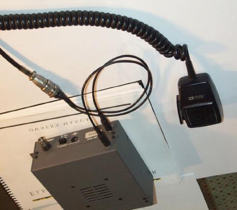
11 Mike installation 11
12 Schematic Diagram of RX and TX K1 SSB modification. 12

13 Ed2 Ed2 PCB (see the Class AB mod.) 13
 connection pins must be added on the K1 RF")
14 The red points indicate the locations at which (female) connection pins must be added on the K1 RF Board. 14

15 K1 SSB modification board upper side layout ATTENTION!: ERRATE POLARIZATION INDICATION on C16 and C17 on PCB only (schematic is correct) 15

16 Bottom layout. The SMD components are pre-assembled on the board On this side only the following non-surface mount components are installed: ( male connectors used to plug the modification board into the K1) 8 pin connector P2 2 pin connector K1/c30 1 pin connector XFIL 1 pin connector P7_1 1 pin connector P7_2 1 pin connector +8V 16
17 SSB Modification Parts List NAME VALUE RS - Code C1 100PF C2 100PF C3 100kpF C4 33PF C5 47PF C6 47PF C7 47PF C8 33PF C9 220pF C10 33pF C pF TRIM (green) C12 1/10PF TRIM. (yellow)rs-code C13 47pF C14 10nF C15 10nF C16 1 UF C17 1 UF C18 1 UF C19 1 UF C20 100PF C21 100pF C22 10nF C23 10nF C24 33PF C25 47PF C26 47PF C27 4.7nF C28 10nF C29 1 UF C30 1uF C pF C32 47pF C33 33PF C34 5/65pF TRIM. (big yellow) Rs-code C35 33pF C pf D1 1N4148 D2 1N
18 D3 1N4148 D4 1N4148 D5 1N4148 J1 NC/3-Ckt L1 100uH P1 2-pin P2 8-pin P6 2-pin P7 2-pin Q1 2n4401 Rs-code Q2 2N3819 Rs-code Q3 2n4401 Q4 BC318 Q5 2n4401 Q6 BCY70 Rs-code Q7 2n4401 Q8 2n4401 R1 27k OHM R2 27k OHM R OHM R OHM R5 22 kohm R6 2.2 kohm R7 330 kohm R8 2.2 kohm R9 22k OHM R10 47k KOHM R11 47k KOHM R kohm R kohm R14 15k OHM R kohm R16 47 OHM R17 15 KOHM R18 1 kohm R19 22 kohm R20 47 kohm R kohm R22 10 kohm R23 10 kohm R24 22 kohm R25 47 kohm 18
19 R26 47K OHM R kohm R OHM R29 15K OHM R kohm REL1 TF2-5V NAIS Rs code RFC1 U1a LM2904 RS-code U1b U2a LM2904 RS-code U2b U3 SA602 RS-code V1 10k OHM Pot Rs-code V2 10k OHM Pot Rs-code V3 1M OHM Pot Rs-code V4 1M OHM Pot Rs-code X1 XTAL 4915KHz RS-code X2 XTAL 4915KHz RS-code X3 XTAL 4915KHz RS-code X4 XTAL 4915KHz RS-code X5 XTAL 4915KHz RS-code X6 XTAL 4915KHz RS-code X7 XTAL 4915KHz RS-code X8 XTAL 4915KHz RS-code X9 XTAL 4915KHz RS-code X10 XTAL 4915KHz RS-code X11 XTAL 4915KHz RS-code X12 XTAL 4915KHz RS-code Z1 Zener 6.2 V 19
CW-ADD. Universal CW Adapter for SSB Transceivers. Assembly manual. Last updated: October 1,
 CW-ADD Universal CW Adapter for SSB Transceivers Assembly manual Last updated: October 1, 2017 ea3gcy@gmail.com Updates and news at: www.ea3gcy.com Thanks for building the Universal CW Adapter kit CW-ADD
12kHz LIF Converter V2.43 9Mhz version
 12kHz LIF Converter V2.43 9Mhz version Please Note: This document supersedes all previously released documents and drawings on the LIF subject. This is the latest and most up-to-date document at this time.
Improving the Performance of the KSB2
 Introduction Improving the Performance of the KSB2 John Grebenkemper, KI6WX KI6WX@pacbell.net July 18, 2002 The following is a set of changes that I have done to my KSB2 and related circuits to improve
IC-781: Installing the Inrad Roofing Filter Mod
 IC-781: Installing the Inrad Roofing Filter Mod The Icom IC-781 roofing filter mod consists of a 6-pole, 4 to 5 khz wide filter followed by a high dynamic range, feedback amplifier. The amplifier provides
Hendricks QRP Kits BITX20A to BITX17A Conversion Instructions
 Hendricks QRP Kits BITX20A to BITX17A Conversion Instructions 30 November 2008 Converting your BITX20A Kit to a BITX17A Kit is not all that complex. It only requires that you change crystals and some resonance
HT-1A Dual Band CW QRP Transceiver. Kit Building Instructions
 HT-A Dual Band CW QRP Transceiver Kit Building Instructions Rev B, July 8, 08 Designed by BD4RG Exclusively distributed by CRKITS.COM and its worldwide distributors Join the group http://groups.io/g/crkits
Building a Bitx20 Version 3
 Building a Bitx20 Version 3 The board can be broken into sections and then built and tested one section at a time. This will make troubleshooting easier as any problems will be confined to one small section.
ILER MK2. Appendices
 ILER MK2 QRP SSB Transceiver in Kit Form Appendices Last update: July 20, 2015 ea3gcy@gmail.com Most recent updates and news at: www.qsl.net/ea3gcy ILER-17 MK2 SSB QRP Transceiver Kit Page 1 APPENDIX 1:
Status Tone Generator
 Eclipse Series RF Technology rfinfo@rftechnology.com.au January 004 Status Tone Generator Operation and Installation This manual is produced by RF technology Pty Ltd 0/8 Leighton Place, Hornsby 077, Australia
N3ZI Kits General Coverage Receiver, Assembly & Operations Manual (For Jun 2011 PCB ) Version 3.33, Jan 2012
 Version 3.33, Jan 2012") N3ZI Kits General Coverage Receiver, Assembly & Operations Manual (For Jun 2011 PCB ) Version 3.33, Jan 2012 Thank you for purchasing my general coverage receiver kit. You can use the photo above as a
N3ZI Kits General Coverage Receiver, Assembly & Operations Manual (For Jun 2011 PCB ) Version 3.33, Jan 2012 Thank you for purchasing my general coverage receiver kit. You can use the photo above as a
S-Pixie QRP Kit. Student Manual. Revision V 1-0
 S-Pixie QRP Kit Student Manual Revision V 1-0 Introduction The Pixie 2 is a small, versatile radio transceiver that is very popular with QRP (low power) amateur radio operators the world over. It reflects
HAMTRONICS TB901 FM EXCITER INSTALLATION, OPERATION, & MAINTENANCE
 HAMTRONICS TB901 FM EXCITER INSTALLATION, OPERATION, & MAINTENANCE GENERAL INFORMATION. The TB901 is a single-channel low power fm transmitter (exciter) designed to provide 300-600 milliwatts continuous
MFJ-752C SIGNAL ENHANCER II
 MFJ-752C SIGNAL ENHANCER II INTRODUCTION The improved MFJ-752C SIGNAL ENHANCER II is comprised of two tunable audio filtering systems designed to clarity and remove interfering signals from both voice
HF Amateur SSB Receiver
 HF Amateur SSB Receiver PCB Set for radio club project http://rhelectronics.net PCB for DIY HF Amateur SSB Receiver 20M The receiver is a simple syperheterodyne type with quartz crystal filter. The circuit
ILER MK2. QRP SSB Transceiver in Kit Form Appendices. Last update: May 01, ILER-17 MK2 SSB QRP Transceiver Kit Page 1
 ILER MK2 QRP SSB Transceiver in Kit Form Appendices Last update: May 01, 2018 ea3gcy@gmail.com Most recent updates and news at: www.qsl.net/ea3gcy ILER-17 MK2 SSB QRP Transceiver Kit Page 1 APPENDIX 1:
A NEW LIFE FOR THE FT-290R TRANSCEIVER! By F5RCT
 A NEW LIFE FOR THE FT-290R TRANSCEIVER! By F5RCT The FT290R is an old amateur radio workhorse which was a very popular transceiver during the 80 s. It is a 2metre multimode portable which can run with
IC-765: Installing the Inrad Roofing Filter Mod
 IC-765: Installing the Inrad Roofing Filter Mod The Icom IC-765 roofing filter mod consists of a 6-pole, 4 khz wide filter followed by a high dynamic range, feedback amplifier. The amplifier provides enough
Connecting the FCC-2 to the Hendricks DC Kits Bob Okas, W3CD
 Connecting the FCC-2 to the Hendricks DC Kits Bob Okas, W3CD This is an application note that describes how you can connect the NorCal FCC-1/2 combination to the DC kits. It involves a few extra components
Step by Step Building PJ meter ARDF Receiver Kit. CRKITS.COM August 5, 2013
 Step by Step Building PJ-80 80-meter ARDF Receiver Kit CRKITS.COM August 5, 2013 What is ARDF? ARDF is the abbreviation of Amateur Radio Direction Finding, or so called Fox Hunting. If you are looking
ICOM IC-201 Allmode Transceiver
 ICOM IC-201 Allmode Transceiver Alignment Procedure Please note: This procedure is reengineered by myself and may be not in accordance with the original procedure from the manufacturer! So I can t accept
TS-950: Installing the Roofing Filter Mod
 TS-950: Installing the Roofing Filter Mod The Kenwood TS-950 Roofing Filter Mod consists of a 6 pole, 4 to 5 khz wide filter followed by a high dynamic range feedback amplifier. The amplifier provides
BITX40 with Raduino - tips and mods
 BITX40 with Raduino - tips and mods Also check out hfsigs blogspot http://bitxhacks.blogspot.co.uk/ Clicks during tuning I assume you are talking about the Raduino clicking as you tune. I'm not having
KWM-2/2A Transceiver THE COLLINS KWM-2/2A TRANSCEIVER
 KWM-2/2A Transceiver Click the photo to see a larger photo Click "Back" button on browser to return Courtesy of Norm - WA3KEY THE COLLINS KWM-2/2A TRANSCEIVER Unmatched for versatility, dependability and
Assembly Manual for VFO Board 2 August 2018
 Assembly Manual for VFO Board 2 August 2018 Parts list (Preliminary) Arduino 1 Arduino Pre-programmed 1 Faceplate Assorted Header Pins Full Board Rev A 10 104 capacitors 1 Rotary encode with switch 1 5-volt
Read This Page First
 Read This Page First If you are reading this you know the manuals are always available at QRPKITS.com. This is version 8.0 of the manual dated 4/27/2016. There is no need to print out the whole assembly
MDT DSB TRANSCEIVER CONSTRUCTION MANUAL. MDT Construction Manual Issue 2 Page 1
 MDT DSB TRANSCEIVER CONSTRUCTION MANUAL MDT Construction Manual Issue 2 Page 1 CONTENTS 1 Introduction... 4 2 DSB vs SSB... 5 3 DSB transmitter... 6 4 Direct Conversion receiver... 7 5 MDT Block Diagram...
The Uniden Grant XL Owners Site
 The Uniden Grant XL Owners Site Modifications page for the Grant XL (For Informational purposes only) The author of this site takes NO responsibility for illegal modifications and/or use of illegally modified
TS-870: Installing the Inrad Roofing Filter Mod
 TS-870: Installing the Inrad Roofing Filter Mod The TS-870 roofing filter mod consists of a 6 pole, 4 to 5 khz wide filter followed by a high dynamic range feedback amplifier. The amplifier provides enough
MST3 SSB TRANSCEIVER BOARD KIT CONSTRUCTION AND OPERATION MANUAL. MST3 Construction and Operation Manual Issue 1 Page 1
 MST3 SSB TRANSCEIVER BOARD KIT CONSTRUCTION AND OPERATION MANUAL MST3 Construction and Operation Manual Issue 1 Page 1 CONTENTS 1 Introduction... 5 2 Block Diagram... 7 3 Circuit Description... 8 3.1 Carrier
FREQUENCY AGILE FM MODULATOR INSTRUCTION BOOK IB
 FMT615C FREQUENCY AGILE FM MODULATOR INSTRUCTION BOOK IB1215-02 TABLE OF CONTENTS SECTION SUBJECT 1.0 Introduction 2.0 Installation & Operating Instructions 3.0 Specification 4.0 Functional Description
FT-897 Alignment. Local Oscillator Adjustment. PLL Adjustment
 FT-897 Local Oscillator Adjustment Reference Frequency Adjustment a. Connect a frequency counter to TP1032. b. Adjust the trimmer capacitor (TC5001) for 67.875000MHz ±5Hz on the frequency counter. c. Connect
Treetop Circuits Owner s Manual for SB-SB-600 Adapter Version 1
 The SB-600 SSB adapter from Treetop Circuits (Fig. 1) is designed specifically as an accessory to the Hammarlund SP-600 series of receivers. It provides enhanced performance on SSB and CW signals, using
: Hacking Bitx Version3B, C: : 20mt to 40mt band: PART I
 : Hacking Bitx Version3B, C: : 20mt to 40mt band: PART I Fig 1: Bitx Ver3C SBL-1 20 Conversion for Bitx40 The picture in Fig1 is a Bitx3C SBL-1 for 40mt band, constructed from the Bitx Version 3C SBL-1
200GTL ALIGNMENT REVISION: 1.0 BURKE MODEL: 200GTL REVISION: 1.2 DATE: 02/14/06. Total Pages: 6 pages. Page:1 print date: 9/23/09
 ALIGNMENT PROCEDURE MODEL: 200GTL REVISION: 1.2 DATE: 02/14/06 PREPARED BY: BURKE Total Pages: 6 pages Page:1 print date: 9/23/09 1 TEST CONDITION: 200GTL ALIGNMENT INSTRUCTION 1.0. TEST TEMPERTAURE: 77
Simple LFO Features. 2. Application. 3. Description. Simple and easy to build LFO module for Analog Synthesizers.
 Simple LFO. Simple and easy to build LFO module for Analog Synthesizers.. Features Square and Triangle waveforms (90 phase shifted) Dual range frequencies Frequency ranges from under Hz up to several khz
CX7 Troubleshooting Index
 CX7 Troubleshooting Index Modification S/1 Newsletter Guide Board Description A/TO A/TO MODE Intermod V1,12 P4.4 A11 Shut off one 35 MHz osc in receive, done sn 244 A/TO Spur V1,12 P1 Reduce A/TO spur,
RS cm transceiver
 RS9044 70cm transceiver ATF-2 Base-unit Modification Dennis Koller (PA4DEN) Schoollaan 2 8392 NM Boyl 0622379901 / 0561421557 1 The receiver Lets start with the receiver, this is the most difficult part.
DEM Part Number L144-28INTCK 144 MHz Transverter Kit and complete kit
 DEM Part Number L144-28INTCK 144 MHz Transverter Kit and complete kit Power Out: Noise Figure and Gain: DC Power Requirement: 50 mw linear minimum 3.5 db NF nominal, 5 dbg maximum 12-15.5 VDC, 13.8 nominal
TS-850: Installing the Inrad Roofing Filter Mod
 TS-850: Installing the Inrad Roofing Filter Mod The TS-850 Roofing Filter Mod consists of a 6 pole, 4 to 5 khz wide filter followed by a high dynamic range feedback amplifier. The amplifier provides enough
RadiØKit Μ CW HAM RADIO TRANSCEIVER KIT. Assembly and operating manual
 RadiØKit-120 20Μ CW HAM RADIO TRANSCEIVER KIT Assembly and operating manual Boreiou Ipirou 78 Kolonos Athens- Greece - 10444 Tel: 210.5150527 210.5132673 www.freebytes.com Thank you for buying RadiØKit-1,
LBI-30398N. MAINTENANCE MANUAL MHz PHASE LOCK LOOP EXCITER 19D423249G1 & G2 DESCRIPTION TABLE OF CONTENTS. Page. DESCRIPTION...
 MAINTENANCE MANUAL 138-174 MHz PHASE LOCK LOOP EXCITER 19D423249G1 & G2 LBI-30398N TABLE OF CONTENTS DESCRIPTION...Front Cover CIRCUIT ANALYSIS... 1 MODIFICATION INSTRUCTIONS... 4 PARTS LIST AND PRODUCTION
hallicrafters PERFORMANCE SPECIFICATIONS MODEL: SR-2000 LATEST REVISION: 18 JAN 66 Code ident # Specification #
 hallicrafters PERFORMANCE SPECIFICATIONS MODEL: SR-2000 LATEST REVISION: 18 JAN 66 Code ident # 26916 Specification # 093-002154 I. GENERAL A. Power input 117V 50-60 cycles from a source capable of delivering
Group build proposal Michael G3WOE
 Group build proposal Michael G3WOE MISSION A 10 radio for Whitton Members BITX Group build project A new mission with a worthwhile and tangible outcome. To provide a new practical focus for the club meetings.
Easy Transmitter. Support ETX_REV5_Manual V2.7 Revised
 Easy Transmitter Introduction The Easy Transmitter kit from qrpkits.com provides a basic, crystal controlled transmitter with VXO tuning to provide a small tuning range around the crystal frequency. It
ERICSSONZ LBI-30398P. MAINTENANCE MANUAL MHz PHASE LOCKED LOOP EXCITER 19D423249G1 & G2 DESCRIPTION TABLE OF CONTENTS
 MAINTENANCE MANUAL 138-174 MHz PHASE LOCKED LOOP EXCITER 19D423249G1 & G2 TABLE OF CONTENTS Page DESCRIPTION... Front Cover CIRCUIT ANALYSIS...1 MODIFICATION INSTRUCTIONS...4 PARTS LIST...5 PRODUCTION
20-27B. Tone Panel. Version 1.10
 20-27B Tone Panel Version 1.10 Printings Version 1.00: 1/16/01 Version 1.10: 10/11/02 TABLE OF CONTENTS SPECIFICATIONS... 1 1.0 GENERAL DESCRIPTION... 2 1.1 Description... 2 1.2 Capabilities and Features...
ALX-SSB Transceiver Kit Assembly Manual
 ALX-SSB Transceiver Kit Assembly Manual 20 August 2018 REV A Transceiver This radio is based on the popular CS-Series SSB Transceiver Kit developed by Adam Rong, BD6CR/4 CRKITS.com. Thanks to B. Bartosh
The ROSE 80 CW Transceiver (Part 1 of 3)
") Build a 5 watt, 80 meter QRP CW Transceiver!!! Page 1 of 10 The ROSE 80 CW Transceiver (Part 1 of 3) Build a 5 watt, 80 meter QRP CW Transceiver!!! (Designed by N1HFX) A great deal of interest has been
Build a 5 watt, 80 meter QRP CW Transceiver!!! Page 1 of 10 The ROSE 80 CW Transceiver (Part 1 of 3) Build a 5 watt, 80 meter QRP CW Transceiver!!! (Designed by N1HFX) A great deal of interest has been
SPECIFICATIONS: Subcarrier Frequency 5.5MHz adjustable, FM Modulated +/- 50KHz. 2nd 11MHz >40dB down from 5.5MHz
 Mini-kits AUDIO / SUBCARRIER KIT EME75 Version4 SPECIFICATIONS: Subcarrier Frequency 5.5MHz adjustable, FM Modulated +/- 50KHz Subcarrier Output 1.5v p-p Output @ 5.5MHz DESCRIPTION & FEATURES: The Notes
BLOCK DIAGRAM - I J Li) N 6. w IS) AF D RIVE R R F D RIVE R R F P OWE R AMP PL L OSC UNIT. LL co X X X Lti X. C X W N O C..) 4 C.
 N 6. w IS) AF D RIVE R R F D RIVE R R F P OWE R AMP PL L OSC UNIT. LL co X X X Lti X. C X W N O C..) 4 C.") MODEL 1-632 BLOCK DIAGRAM tl LL co a. LL O ox X X X X < X C.) W N C U) LL CO aa 1.11 t O - I J Ul Li) Lti N w IS) 1 X. C X Ir t AF D RIVE R X - LL C.) CD r.--1111 MOP U) N N 6 PL L OSC UNIT R F D RIVE
MODEL 1-632 BLOCK DIAGRAM tl LL co a. LL O ox X X X X < X C.) W N C U) LL CO aa 1.11 t O - I J Ul Li) Lti N w IS) 1 X. C X Ir t AF D RIVE R X - LL C.) CD r.--1111 MOP U) N N 6 PL L OSC UNIT R F D RIVE
ALX-SSB 5 Band Filter Assembly Manual 19 November 2018
 ALX-SSB 5 Band Filter Assembly Manual 19 November 2018 Contents Theory of Operation:... 1 Figure 1... 2 Parts Included:... 4 Board Overview:... 5 Figure 2... 5 Figure 3... 5 Board Assembly:... 6 Cable
From German Radio Amateur Jochen Heilemann (DG2IAQ) Dragon SS-201 Version MHz AM/FM/SSB Handheld Transceiver, 4-6 Watts
 Dragon SS-201 Version MHz AM/FM/SSB Handheld Transceiver, 4-6 Watts") Introduction The beautiful handheld transceiver came with a very quiet and low modulation. The original FM deviation was only 1,5 khz on mine! With the FM deviation pot on maximum! Normally you should
Introduction The beautiful handheld transceiver came with a very quiet and low modulation. The original FM deviation was only 1,5 khz on mine! With the FM deviation pot on maximum! Normally you should
Building the Sawdust Regenerative Receiver
 Building the Sawdust Regenerative Receiver Introduction The Sawdust is a super regenerative receiver using the basic Armstrong design architecture. The receiver uses one toroidal transformer to provide
ISOTERM-MULTICON TRAVELLER
 ISOTERM-MULTICON TRAVELLER SETTING UP INSTRUCTIONS FOR DATA INTERFACE de G3LIV July 2012 Page 1-1 Welcome to the World of PSK-31. Thank you for purchasing this ISOTERM. I hope it will give you hours of
Microphone audio, from the MFJ-1278B to your transmitter. Ground, audio and PTT common. Push-to-talk, to allow the MFJ-1278B to key your transmitter.
 Computer interfacing, covered in the previous chapter, is only half the interfacing task. The other half is connecting your MFJ-1278B to your radios. MFJ-1278B Radio Ports Interfacing the MFJ-1278B to
KN-Q10 Assembly Manual
 KN-Q10 Assembly Manual Translated by Adam Rong, BD6CR/4 with permission from Ke Shi, BA6BF Edited by Stephen, VK2RH Revision B, Oct 14, 2010 Thank you for purchasing the KN-Q10 4 Band SSB/CW Dual Mode
Building and Operating: Son of Zerobeat A PIC based CW zerobeat indicator from Jackson Harbor Press
 Building and Operating: Son of Zerobeat A PIC based CW zerobeat indicator from Jackson Harbor Press Ed Nisley, KE4ZNU, wrote an article published in the August, September and October of 1996 issues of
GRAND STRAND AMATEUR RADIO CLUB
 The GRAND STRAND AMATEUR RADIO CLUB (GSARC) Myrtle Beach SC is offering used amateur related equipment for sale. Written bids may be submitted to the GSARC up to Friday, November 23 rd, 2018. Only currently
Assembly Manual V1R2B-Rev1.0D
 Assembly Manual V1R2B-Rev1.0D for 4 State QRP MagicBox - Solid State Transmit/Receive System Designed by: Jim Kortge, K8IQY Copyright 2009-2012 - All rights reserved This system is the result of some brainstorming
Polyphase network kit
 Polyphase network kit 1. Introduction This polyphase network module is designed to be used with the QRP Labs receiver module kit. It takes as inputs, four phase audio from the Quadrature Sampling Detector
MFJ SIGNAL ENHANCER II
 MFJ SIGNAL ENHANCER II Model MFJ-752D INSTRUCTION MANUAL CAUTION: Read All Instruction Before Operating Equipment MFJ ENTERPRISES, INC. P.O. BOX 494, MISSISSIPPI STATE, MS 39762, USA 925-0037D-752D-REV
INTERNATIONAL RADIO CORP
 I N R A D INTERNATIONAL RADIO CORP 13620 Tyee Road Umpqua, OR 97486 (541) 459-5623 fax (541) 459 5632 E-mail: inrad@rosenet.net www.qth.com/inrad IC-775 ROOFING FILTER INSTALLATION INSTRUCTIONS The IC-775
The LZA2027 Tone Termination Panel Instruction and Programming Manual
 The LZA2027 Tone Termination Panel Instruction and Programming Manual BK Radio 7100 Technology Drive West Melbourne, FL 32904 Phone: (800) 648-0947 Fax: (321) 984-0434 www.relm.com 0300-30944-900 Rev.
CS Series SSB Transceiver
 CS Series SSB Transceiver Single Band SSB Transceiver Kit Manual Rev. Preliminary Release CRKITS.COM April 8, 2017 Preliminary Release Original written by Adam Rong, BD6CR/4 Modified by Larry Lovell, N7RGW
BITX40 with Raduino - tips and mods
 BITX40 with Raduino - tips and mods Also check out hfsigs blogspot http://bitxhacks.blogspot.co.uk/ IMPORTANT NOTE DO NOT let the final pa transistor tag touch ground. Any heatsink used must be isolated
TS-930: Installing the Inrad Roofing Filter Mod
 TS-930: Installing the Inrad Roofing Filter Mod The TS-930 roofing filter mod consists of a 6 pole, 4 to 5 khz wide filter followed by a high dynamic range, feedback amplifier. The amplifier provides enough
SoftRock v6.0 Builder s Notes. April 6, 2006
 SoftRock v6.0 Builder s Notes April 6, 006 Be sure to use a grounded tip soldering iron in building the v6.0 SoftRock circuit board. The soldering iron needs to have a small tip, (0.05-0. inch diameter),
HAMTRONICS TA51 (REV A) VHF FM EXCITER: INSTALLATION, OPERATION, & MAINTENANCE
 VHF FM EXCITER: INSTALLATION, OPERATION, & MAINTENANCE") HAMTRONICS TA51 (REV A) VHF FM EXCITER: INSTALLATION, OPERATION, & MAINTENANCE GENERAL INFORMATION. The TA51-144 is a single-channel vhf fm exciter designed to provide 2 to 3 Watts continuous duty output
HAMTRONICS TA51 (REV A) VHF FM EXCITER: INSTALLATION, OPERATION, & MAINTENANCE GENERAL INFORMATION. The TA51-144 is a single-channel vhf fm exciter designed to provide 2 to 3 Watts continuous duty output
Frequency Coverage MHz RF Power Output 30W SSB / 9W AM/ 30W FM Dual Finals on Heat Sink Modes AM, FM, USB, LSB Microprocessor
 MAGNUM M-257 30W AM/ /FM/SSB 10--11 Meterr Mobile Trranscei ivverr n Prri iiccee: : US$ 250..00 eexx ssttoocckk JJaakkaarrttaa (Arrrri ( iivvi iinngg 2 d weeeekk iinn i Maarrcchh) ) SPECIFICATIONS Frequency
Cross-Connect Interface
 Cross-Connect Interface User Manual Document #: 050-015-0036R01 November 2006 TASC Systems Inc. Langley, BC Canada Cross-Connect System User Manual Preface This document describes the installation, commissioning
RECEIVER TEST OSCILLATOR Rev G, January 16, 2018 Copyright 2018, Elecraft, Inc., All Rights Reserved
 E L E C R A F T XG RECEIVER TEST OSCILLATOR Rev G, January 6, 08 Copyright 08, Elecraft, Inc., All Rights Reserved Introduction The Elecraft XG is a crystal oscillator with accurate µv and 50 µv output
PC to Radio Audio and Key-line Interface
 PC to Radio Audio and Key-line Interface Background - This simple interface was developed to capacitive couple audio signals between a radio and PC, to provide a means of adjusting audio levels between
Demo Circuit DC550A Quick Start Guide.
 May 12, 2004 Demo Circuit DC550A. Introduction Demo circuit DC550A demonstrates operation of the LT5514 IC, a DC-850MHz bandwidth open loop transconductance amplifier with high impedance open collector
University of North Carolina, Charlotte Department of Electrical and Computer Engineering ECGR 3157 EE Design II Fall 2009
 University of North Carolina, Charlotte Department of Electrical and Computer Engineering ECGR 3157 EE Design II Fall 2009 Lab 1 Power Amplifier Circuits Issued August 25, 2009 Due: September 11, 2009
OBJECTIVES EQUIPMENT LIST
 1 Reception of Amplitude Modulated Signals AM Demodulation OBJECTIVES The purpose of this experiment is to show how the amplitude-modulated signals are demodulated to obtain the original signal. Also,
Complete your carrier-current audio system with an AM or FA4 receiver:
 r LAST MONTH WE WENT OVER the operating theory of a carrier-current transmitter, and then showed you how to build one. Now we will describe two receivers that can be used with that transmitter. One receiver
Construction Guide of TH300S
 Construction Guide of TH300S TH300S is a 2-band SSB/CW transceiver, used with DDS as LO, and features dual operation system ham band and general coverage band. A doubly balanced diode ring mixer is used
QRPver 20M Transceiver Review By Edward R. Breneiser, WA3WSJ
 QRPver 20M Transceiver Review By Edward R. Breneiser, WA3WSJ I was looking around for a door prize for the Boschveldt QRP Club MOC 2018 Event and found a unique QRP site. The website is QRPver.com and
Cubic Astro 103 Restoration Notes
 Cubic Astro 103 Restoration Notes W7CPA February 2016 I restored a Cubic Astro 103 a few years ago and have enjoyed operating it for years. It s a very nice geezer wireless and the last amateur radio product
ICOM IC-7200 Military
 DG2IAQ Modification notes 20-Jul-2003, rev. 21. Feb. 2009 / p. 1 The famous ICOM IC-7200 is a great transceiver and I like it very much. As announced in several forums I realized that it has some (few)
HF Receivers, Part 2
 HF Receivers, Part 2 Superhet building blocks: AM, SSB/CW, FM receivers Adam Farson VA7OJ View an excellent tutorial on receivers NSARC HF Operators HF Receivers 2 1 The RF Amplifier (Preamp)! Typical
Norfolk Amateur Radio Club
 Norfolk Amateur Radio Club The Transmitter & Transmitter Interference Nick M0HGU & Steve G3PND Plan for the Day The Transmitter Introduction, Block diagrams Oscillators, Buffers & Multipliers Modulation
Goals: Board ID's in System Transmitter components/modules TLD5321A exciter board
 Micor Unified Chassis Base Station Conversion to A Ham Band Repeater by Lawrence Glaister VE7IT November 2002 Goals: -To duplex a base station radio set for repeater usage. - To mount and tune a micor
RITEK RIT for Collins KWM-2/2A 10/01/2002
 RITEK RIT for Collins KWM-2/2A 10/01/2002 The RITEK RIT (receiver incremental tuning) control was developed for KWM-2/2A in 1992 to "clarify" received signals differing from the transmit frequency indicated
LnR Precision, Inc. 107 East Central Avenue, Asheboro, NC
 LD5 CW/SSB QRP Transceiver Quick guide manual Description: At the development base of the digital signal processing unit, an algorithm is embedded for IQ processing of the channels with phase suppression
Stereo 3.7W Class D Audio Amplifier
 Stereo 3.7W Class D Audio Amplifier Created by Bill Earl Last updated on 2014-10-28 10:45:16 AM EDT Guide Contents Guide Contents Overview Specifications: What is a Class D Amplifier? Other Audio amps
BAND DECODER and CONTROLLE R. Accessibility Upgrade and Operating Instructions
 ELE CRAFT KRC2 BAND DECODER and CONTROLLE R Accessibility Upgrade and Operating Instructions Revision A, March 4, 2004. Copyright 2004, Elecraft; All Rights Reserved Introduction The KRC2 Accessibility
Bitx Version 3 Linear Amplifier Assembly
 Bitx Version 3 Linear Amplifier Assembly The power supply section has 2 options. 1 - AC input and a higher voltage on the IRF510 and +12 volts to the bitx. 2 - +12 volts applied to both the final and the
Pacific Antenna - Easy TR Switch
 Pacific Antenna - Easy TR Switch Kit Description The Easy TR Switch is an RF sensing switch that can be used to switch an antenna between a receiver and transmitter. It also has a second switched pair
ATV Modulator User Manual
 ATV Modulator User Manual FMTV Modulator by Grant ZL1WTT & Keith ZL1BQE 20 February 2004 Page 1 Display board layout The controller consists of a 2x 16 LCD display with three push buttons and a rotary
Model AAA-1C. Addendum to AAA-1B documentation
 Model AAA-1C. Addendum to AAA-1B documentation 1. Specifications for Model AAA-1C (11) General Output impedance Power supply (1) Maximal output voltage (10) Physical size 50 Ohms, BNC connector on control
FM Audio/Squelch Board by Steve Dold, W6KCS w6kcs (at) stevedold (dot) com
 stevedold (dot) com") FM Audio/Squelch Board by Steve Dold, W6KCS w6kcs at stevedold dot com Board hardware version 7-8 Firmware version 7.x This board connects to an FM receiver's discriminator/detector and provides squelched,
FM Audio/Squelch Board by Steve Dold, W6KCS w6kcs at stevedold dot com Board hardware version 7-8 Firmware version 7.x This board connects to an FM receiver's discriminator/detector and provides squelched,
INSTRUCTION MANUAL MODEL 2779 SUBCARRIER MODULATOR
 INSTRUCTION MANUAL MODEL 2779 SUBCARRIER MODULATOR Data, drawings, and other material contained herein are proprietary to Cross Technologies, Inc., and may not be reproduced or duplicated in any form without
MAINTENANCE MANUAL AUDIO MATRIX BOARD P29/
 MAINTENANCE MANUAL AUDIO MATRIX BOARD P29/5000056000 TABLE OF CONTENTS Page DESCRIPTION................................................ Front Cover CIRCUIT ANALYSIS.............................................
An Experimental Polyphase Receiver by Bozidar Pasaric 9A2HL, Croatia Introduction
 An Experimental Polyphase Receiver by Bozidar Pasaric 9A2HL, Croatia Introduction The Tayloe receiver is a new type of digital SSB and single-sided CW RX, invented and patented by Dan Tayloe, N7VE. It
HAMTRONICS R313 VHF FM RECEIVER: INSTALLATION, OPERATION, & MAINTENANCE
 HAMTRONICS R313 VHF FM RECEIVER: INSTALLATION, OPERATION, & MAINTENANCE GENERAL INFORMATION. The R313 is the latest in a series of popular receivers for demanding applications which require exceptional
Handy dandy little circuit #17 #17
 Handy dandy little circuit #17 #17 Download # 17 in PDF There are a lot of alarm systems on the market but you might be inclined to build your own. This little project can be put together using inexpensive
Operation Manual. Model SG Elenco Precision Wide Band Signal Generator
 99 Washington Street Melrose, MA 02176 Phone 781-665-1400 Toll Free 1-800-517-8431 Visit us at www.testequipmentdepot.com Elenco Precision Wide Band Signal Generator Model SG-9000 Operation Manual CONTENTS
DIY Function Generator XR2206
 DIY Function Generator XR2206 20Hz 100KHz http://radiohobbystore.com Components List: Resistors: R1, R2 1% Metal Film 5K1 R4 1% Metal Film 10K R5 1% Metal Film 3K R10 5% Carbon Film 10R R3, R9 Potentiometer
HAMTRONICS TA & TA VHF FM EXCITER: ASSEMBLY, INSTALLATION, OPERATION, & MAINTENANCE
 HAMTRONICS TA51-144 & TA51-220 VHF FM EXCITER: ASSEMBLY, INSTALLATION, OPERATION, & MAINTENANCE GENERAL INFORMATION. The TA51-144 is a single-channel vhf fm exciter designed to provide 2 Watts continuous