Frequency Doubler 3,2 6,4 GHz to 6,2 12,8 GHz based on HMC204MS
|
|
|
- Gerard Jones
- 5 years ago
- Views:
Transcription


1 Frequency Doubler 3,2 6,4 GHz to 6,2 12,8 GHz based on HMC204MS Matthias, DD1US, January 4 th 2018, Rev 3.0 Hello, as I just finished refurbishing a R&S SMIQ06 signal generator, which covers the frequency range up to 6.4 GHz, I wanted to extend my measurement setup now to cover also the 3cm ham radio band / KUband up to 12 GHz. As Es Hail-2 will now hopefully soon gets activated I needed to modify some KU- Band LNBs. Recently, PCBs with the Hittite HMC204MS passive frequency doubler became available for very low cost on Ebay. Thus, I decided to build a frequency doubler based on such a board in order to be able to generate signals also in the frequency range 6,4 12,8 GHz. The boards are available as a PCB with a tin-plated lid for shielding or embedded in a milled aluminium encasing. Both units are using female SMA connectors for the input and output ports. Here are pictures of the 2 versions: As I planned to integrate the doubler together with other components in a larger encasing I decided to go for the cheaper PCB with the simple lid for shielding. Hindsight I should have decided for the version in the milled aluminium casing as the PCB board is very thin and fragile. The HMC204MS (from Hittite, which is now part of Analog Devices Inc.) is a passive frequency doubler for an input frequency range of 4-8 GHz with a conversion loss of typically 17dB (max. 21dB). The suppression of undesired fundamental and higher order harmonics is typically 42 db (min. 35dB) with respect to the input signal level. The optimum input power level is +15dBm. 1

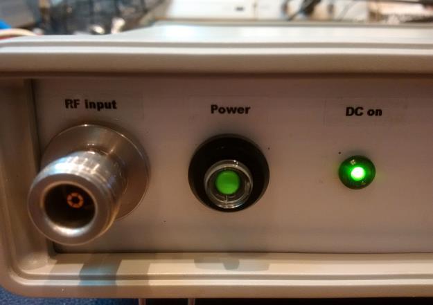
2 Here is a sketch of the block diagram of my initially planned setup: As I was lacking a suitable input amplifier I build the setup above also omitting the bypass relays, which I might add at a later stage. Here are pictures of my setup: 2


3 3

4 Unfortunately, it turned out that the diplex filter at the output, which I wanted to use to terminate the unwanted subharmonic signal and filter out the frequency doubled signal, was not suitable. The part number is P/N M and they were produced by a company in Roma/Italy called Elettronica S.p.A. Roma. You can find a detailed description of the diplexer in a separate document on my website. The high pass section of the diplexer was in fact a band pass filter which did strongly attenuate signals already at 6.5 GHz and above. Therefore, I removed this diplexer and the subsequent measurements were done only with the passive doubler and a broadband amplifier. The amplifier MITEQ is boosting the output levels by about db at 5 GHz and above. You can also find a description of this amplifier in a separate document on my website. Here is a diagram of the measured output signals: The green curve P(2xfin) shows the output level of the wanted output signal (at twice the input frequency) as a function of the input frequency. Please note that I did not calibrate for the losses of the coaxial cable between the output of the unit and the input of the spectrum analyser which I used for the measurements. Thus, the real output level will be a bit higher, I estimate 0.5 db at the lower frequencies (4 GHz) and 2dB at the higher frequencies (13 GHz). The red curve P(fin) shows the 4
.")
5 residual input signal of the doubler measured at the output port. The input level was always set to +16 dbm (minus the losses of the coaxial cable between the signal generator and input of the doubler which I did not calibrate out). The brown and the yellow curves show the corresponding output signals at 3x and 4x of the input frequency. The measurement limit was about -37dBm. The measurement results are in line with the datasheet parameters of the HMC204MS. In the next step I inserted an amplifier before the doubler in order to reduce the needed input power to -20dBm. I also added a high pass filter after the second amplifier to reduce the level of the subharmonic signal. Descriptions of the high-gain amplifier MITEQ AMF-5S P and the 5.5 GHz high-pass filter HPF5500 are available in separate documents on my website. Here is a diagram of the measured output signals: The input signal with the frequency fin is suppressed nicely by the high-pass filter in the range up to 5 GHz. However, the 3 rd harmonic 3xfin increased significantly probably due to the first amplifier with a P1dB=13dBm driven into compression. Even the 4 th harmonic 4xfin increased in some areas. 5

6 Thus, next I added a 12GHz low-pass filter between the 5.5 GHz high-pass filter and the RF-output port. The lowpass filter is from Bendix. The part number is no longer readable. It features a very flat passband and a cut-off frequency of slightly above 12 GHz. The attenuation at 13.5 GHz is 40dB. Here is a diagram of the measured output signals: As can be seen the filter improved the output level of the unwanted harmonics 3xfin and 4xfin above 12 GHz effectively. The compromise here is that also the wanted signal at 2xfin is attenuated above 12 GHz. 6


7 Still, I was not completely happy because the 3 rd harmonic (3xfin) in the frequency range fin = MHz was quite high. After some search I found a low-pass filter from HP Agilent which were supposedly used in HP test equipment such as 8671B, 8672B, 8672A, 8673D and 8970B. Its cut-off frequency is specified to be 6.2 GHz. I measured the 3dB cut-off frequency to be 6.5 GHz which fitted well for my system. I inserted this low-pass filter between the input amplifier and the frequency doubler. Here is a diagram of the measured output signals: The unwanted the 3 rd harmonic (3xfin) is improved nicely in the frequency range fin = MHz. Whether it also improved in the range 4500 MHz to 6400 MHz is unclear as the previous measurement was limited to -40dBm. Anyway, with the improved measurement range down to - 55dBm it can be guaranteed that the 3 rd harmonic is -55dBm or below at 4250 MHz and above. 7


8 Here are some pictures of the final setup: 8

9 I have not yet decided whether I will add relays as I had originally envisioned in order to be able to bypass the frequency doubler when not needed. Anyhow, I have now a frequency doubler covering the range fin = GHz respectively fout = GHz with quite good performance. The needed input level is approx. -20dBm and the output level between 6.4 and 12 GHz is dbm rolling off to -9dBm at 12.8 GHz. I am always interested in feedback. Please send it to the address given below. Best regards Matthias dd1us@amsat.org Homepage: 9
Frequency Doubler 4-8 GHz based on HMC204MS
 Frequency Doubler 4-8 GHz based on HMC204MS Matthias, DD1US, December 2 nd 2018, Rev 2.0 Hello, recently, PCBs with the Hittite HMC204MS passive frequency doubler became available for very low cost on
Wideband Amplifier MITEQ AMF5S P
 Wideband Amplifier MITEQ AMF5S-040080-12-13P Matthias, DD1US, December 2 nd 2018 I am presently building a frequency doubler to extend my measurement setup to higher frequencies. I am using a frequency
Analysis of an unknow biconical omni antenna for S-band
 Analysis of an unknow biconical omni antenna for S-band Matthias, DD1US, January 3 rd 2019 Recently I found some interesting omnidirectional active antennas on Ebay. The original purpose and application
Improving the ADF5355 synthesizer board (Version with Touch-Display)
") Improving the ADF5355 synthesizer board (Version with Touch-Display) Hello, Matthias, DD1US, March 24 th 2018, rev 1.1 Searching for a way to extend the frequency range of my test equipment I decided to
Improving the ADF5355 synthesizer board (Version with Touch-Display) Hello, Matthias, DD1US, March 24 th 2018, rev 1.1 Searching for a way to extend the frequency range of my test equipment I decided to
The logarithmic periodic antenna Hyperlog 7025
 The logarithmic periodic antenna Hyperlog 7025 Matthias Bopp DD1US April 20 th 2012 I have been interested in broadband antennas for a long time. Recently I updated my little portable setup which I use
The WellGood active loop antenna tested in combination with the Airspy HF+ SDR
 The WellGood active loop antenna tested in combination with the Airspy HF+ SDR Matthias DD1US, April 9 th 2018 I was always interested in active loop antennas, especially for portable operations. However,
Data Sheet SC5317 & SC5318A. 6 GHz to 26.5 GHz RF Downconverter SignalCore, Inc. All Rights Reserved
 Data Sheet SC5317 & SC5318A 6 GHz to 26.5 GHz RF Downconverter www.signalcore.com 2018 SignalCore, Inc. All Rights Reserved Definition of Terms 1 Table of Contents 1. Definition of Terms... 2 2. Description...
A low cost signal generator for 54 MHz to 13.4 GHz. Matthias Bopp DD1US
 A low cost signal generator for 54 MHz to 13.4 GHz Matthias Bopp DD1US Microwave & EME Symposium in Gajow / Poland, June 9 th 2018 Agenda Motivation ADF5355 IC Chinese low cost modules Module including
Dressler ARA-2000 active antenna what s inside?
 Dressler ARA-2000 active antenna what s inside? Matthias Bopp Updated October 23 rd 2011 Dressler active antennas have an excellent reputation and thus I was interested how they are comprised before buying
87415A microwave system amplifier A microwave. system amplifier A microwave system amplifier A microwave.
 20 Amplifiers 83020A microwave 875A microwave 8308A microwave 8307A microwave 83006A microwave 8705C preamplifier 8705B preamplifier 83050/5A microwave The Agilent 83006/07/08/020/050/05A test s offer
Harmonic Mixers And their application with Spectrum Analysers Application Note Revision: February 2009
 General A harmonic mixer is another term for a sub-harmonic mixer (SHM) but is more commonly used for systems using higher multiples of the input local oscillator (LO) to produce the mixing LO. They lend
HAM RADIO. 1 KW SSPA 144 MHz RF POWER AMPLIFIER SWR 65:1
 AMD 1000 AR 144 November 2011 First Edition HAM RADIO 1 KW SSPA 144 MHz RF POWER AMPLIFIER SWR 65:1 RF Dispositive : MRF6VP61K25HR6 Freescale Frequency Range 142-146 MHz 4 W Input ± 0.5 W ( @ 1 KW Carrier
FREQUENCY MULTIPLIERS
 FREQUENCY MULTIPLIERS ISO 9001 REGISTERED COMPANY PASSIVE AND ACTIVE Doublers Triplers Higher-Order Products TABLE OF CONTENTS CONTENTS PAGE INTRODUCTION 2 TECHNICAL OVERVIEW 2 Technical Discussion 3 Design
PRODUCT APPLICATION NOTES
 Extending the HMC189MS8 Passive Frequency Doubler Operating Range with External Matching General Description The HMC189MS8 is a miniature passive frequency doubler in a plastic 8-lead MSOP package. The
The 144MHz Anglian 3 transverter
 The 144MHz Anglian 3 transverter A high performance 144/28MHz transverter G4DDK document issue 1 12/9/16 Introduction Anglian 3 is an update to the 144MHz Anglian 2 transverter. The Anglian 2 is no longer
PARAMETER CONDITIONS TYPICAL PERFORMANCE Operating Supply Voltage 3.1V to 3.5V Supply Current V CC = 3.3V, LO applied 152mA
 DESCRIPTION LT5578 Demonstration circuit 1545A-x is a high linearity upconverting mixer featuring the LT5578. The LT 5578 is a high performance upconverting mixer IC optimized for output frequencies in
GaAs MMIC Double Balanced Mixer. Description Package Green Status
 GaAs MMIC Double Balanced Mixer MM1-0212SSM 1. Device Overview 1.1 General Description The MM1-0212SSM is a highly linear GaAs MMIC double balanced mixer. MM1-0212SSM is a low frequency, high linearity
SHF Communication Technologies AG. Wilhelm-von-Siemens-Str. 23D Berlin Germany. Phone Fax
 SHF Communication Technologies AG Wilhelm-von-Siemens-Str. 23D 12277 Berlin Germany Phone +49 30 772051-0 Fax ++49 30 7531078 E-Mail: sales@shf.de Web: http://www.shf.de Datasheet SHF 100 BPP Broadband
Broadcast Concepts Inc NW 102 Road Suite 4 Medley FL Tel: : Fax Model P50FM42MH-SMA2 FM Pallet Amplifier Module
 Model P50FM42MH-SMA2 FM Pallet Amplifier Module This amplifier module is ideal for driver stages in FM Broadcast transmitters. 86 110MHz 28Volts Pout: 50W CW minimum 40dB Gain Class AB MACOM MRF173 Mosfet
Voltage Variable Equalizer
 Surface Mount Voltage Variable Equalizer 5Ω 95 to 2 MHz The Big Deal Adjustable attenuation slope Supply voltage from + to + IP3 +55 dbm typical Minimal deviation from linear loss, ±.5dB CASE STYLE: HE1354
Low Power GaAs MMIC Double Balanced Mixer. Refer to our website for a list of definitions for terminology presented in this table.
 Low Power GaAs MMIC Double Balanced Mixer MM1-0212LSM 1. Device Overview 1.1 General Description The MM1-0212LSM is a low power GaAs MMIC double balanced mixer that operates at LO powers as a low as +1
A precise reference frequency not only for your ham radio station Rev 0.5
 Langenbrettach, April 2nd 2010 Matthias Bopp A precise reference frequency not only for your ham radio station Rev 0.5 A ham radio station needs a stable reference frequency if you want to move to very
Physical Test Setup for Impulse Noise Testing
 Physical Test Setup for Impulse Noise Testing Larry Cohen Overview Purpose: Use measurement results for the EM coupling (Campbell) clamp to determine a stable physical test setup for impulse noise testing.
FEU (Front End Unit) for Optic Repeater
 for Optic Repeater") FEU (Front End Unit) for Optic Repeater 1. Specification 1.1. All Items Parameter Specification Comments RX1 RX2 TX Frequency Range. 1750.625 ~ 1769.375MHz 1750.625 ~ 1769.375MHz 1840.625 ~ 1859.375MHz
FEU (Front End Unit) for Optic Repeater 1. Specification 1.1. All Items Parameter Specification Comments RX1 RX2 TX Frequency Range. 1750.625 ~ 1769.375MHz 1750.625 ~ 1769.375MHz 1840.625 ~ 1859.375MHz
BROADBAND DISTRIBUTED AMPLIFIER
 ADM1-26PA The ADM1-26PA is a complete LO driver solution for use with all Marki mixers up to 26. GHz. This single-stage packaged GaAs MMIC distributed amplifier integrates all required biasing circuitry.
Alcatel White Box 24GHz Transceiver experiments and modifications
 Alcatel White Box 24GHz Transceiver experiments and modifications A set of working notes, measurements and comments PSU Need to supply : -5V up to ~ 30mA for Rx and PA modules +5.2V 1A for Rx and Tx mixer
DC to 400 MHz (40 db Typ. Isolation up to 20 GHz)
") Coaxial Low Pass Filter 5Ω DC to 4 MHz (4 db Typ. Isolation up to 2 GHz) The Big Deal Very good rejection, 4 db typ. up to 2 GHz Excellent power handling, 1W Rugged unibody construction CASE STYLE: FF1118
Coaxial Low Pass Filter 5Ω DC to 4 MHz (4 db Typ. Isolation up to 2 GHz) The Big Deal Very good rejection, 4 db typ. up to 2 GHz Excellent power handling, 1W Rugged unibody construction CASE STYLE: FF1118
With these 2 sections option we try to get the most out of your LD Mosfet Transistor.
 LPF 2M 1KW+ LDMOS LPF 2M 1KW+ LDMOS is an 1KW+ Filter, developed for use with the latest generation High Power LD Mosfet transistors. These extreme high power semiconductors have very high gain and often
Improving Amplitude Accuracy with Next-Generation Signal Generators
 Improving Amplitude Accuracy with Next-Generation Signal Generators Generate True Performance Signal generators offer precise and highly stable test signals for a variety of components and systems test
and GHz. ECE Radiometer. Technical Description and User Manual
 E-mail: sales@elva-1.com http://www.elva-1.com 26.5-40 and 76.5-90 GHz ECE Radiometer Technical Description and User Manual November 2008 Contents 1. Introduction... 3 2. Parameters and specifications...
EEC 134AB. Application Note. Radar System Design for RF. By: Yharo Torres. Group: Diode Hard 3. Fundamental Design of Radar:
 EEC 134AB Application Note Radar System Design for RF By: Yharo Torres Group: Diode Hard 3 Fundamental Design of Radar: The radar design we decided to go with for the quarter 2 design is one that is fundamentally
EE 3324 Electromagnetics Laboratory
 EE 3324 Electromagnetics Laboratory Experiment #10 Microstrip Circuits and Measurements 1. Objective The objective of Experiment #8 is to investigate the application of microstrip technology. A precision
Parameter Symbol Units MIN MAX. RF Input power (CW) Pin dbm +20
 Pin dbm +20") AMT-A0119 0.8 GHz to 3 GHz Broadband High Power Amplifier W P1dB Data Sheet Features 0.8 GHz to 3GHz Frequency Range Class AB, High Linearity Gain db min 55 db Typical Gain Flatness < ± 1.2 db Typical
AMT-A0119 0.8 GHz to 3 GHz Broadband High Power Amplifier W P1dB Data Sheet Features 0.8 GHz to 3GHz Frequency Range Class AB, High Linearity Gain db min 55 db Typical Gain Flatness < ± 1.2 db Typical
User Manual CXE Rev.002 Broadband Cable Networks March 3, (10) CXX Series. User Manual. Teleste Corporation CXE880.
 CXX Series. User Manual. Teleste Corporation CXE880.") Broadband Cable Networks March 3, 2008 1(10) CXX Series User Manual Teleste Corporation CXE880 Fibre Node Broadband Cable Networks March 3, 2008 2(10) Introduction The CXE880 is a fibre deep optical node
Broadband Cable Networks March 3, 2008 1(10) CXX Series User Manual Teleste Corporation CXE880 Fibre Node Broadband Cable Networks March 3, 2008 2(10) Introduction The CXE880 is a fibre deep optical node
With these 2 sections option we try to get the most out of your LD Mosfet Transistor.
 LPF 6M 1KW+ LDMOS LPF 6M 1KW+ LDMOS is an 1KW+ Filter, developed for use with the latest generation High Power LD Mosfet transistors. These extreme high power semiconductors have very high gain and often
S.A. Torchinsky, A. van Ardenne, T. van den Brink-Havinga, A.J.J. van Es, A.J. Faulkner (eds.) 4-6 November 2009, Château de Limelette, Belgium
 4-6 November 2009, Château de Limelette, Belgium") WIDEFIELD SCIENCE AND TECHNOLOGY FOR THE SKA SKADS CONFERENCE 29 S.A. Torchinsky, A. van Ardenne, T. van den Brink-Havinga, A.J.J. van Es, A.J. Faulkner (eds.) 4-6 November 29, Château de Limelette, Belgium
WIDEFIELD SCIENCE AND TECHNOLOGY FOR THE SKA SKADS CONFERENCE 29 S.A. Torchinsky, A. van Ardenne, T. van den Brink-Havinga, A.J.J. van Es, A.J. Faulkner (eds.) 4-6 November 29, Château de Limelette, Belgium
SHF Communication Technologies AG. Wilhelm-von-Siemens-Str. 23D Berlin Germany. Phone Fax
 SHF Communication Technologies AG Wilhelm-von-Siemens-Str. 23D 12277 Berlin Germany Phone +49 30 772 051-0 Fax +49 30 753 10 78 E-Mail: sales@shf-communication.com Web: www.shf-communication.com Datasheet
V1.0 TBFL1 TBFL1 TRANSIENT LIMITER
 V1.0 TBFL1 TBFL1 TRANSIENT LIMITER The TBFL1 is a combined transient limiter / attenuator / high pass filter, designed to provide optimum protection of spectrum analyzer or measurement receiver inputs
SHF Communication Technologies AG. Wilhelm-von-Siemens-Str. 23D Berlin Germany. Phone Fax
 SHF Communication Technologies AG Wilhelm-von-Siemens-Str. 23D 12277 Berlin Germany Phone ++49 30 772 051-0 Fax ++49 30 753 10 78 E-Mail: sales@shf.de Web: http://www.shf.de Datasheet SHF D837 A Differential
GPS Active Antenna With GPRS Measurement Report
 GPS Active Antenna With GPRS Measurement Report Summary: This report is to account for the measurement setup and results of 4x23mm and mm height GPS active antenna combined with GPRS antenna measurement.
Using the OML Millimeter Wave Vector Network Analyzer Frequency Extension Modules with the HP 8510 Vector Network Analyzer
 Using the OML Millimeter Wave Vector Network Analyzer Frequency Extension Modules with the HP 8510 Vector Network Analyzer OML has developed a series of millimeter wave Frequency Extension Modules (Modules)
SHF Communication Technologies AG. Wilhelm-von-Siemens-Str. 23D Berlin Germany. Phone Fax
 SHF Communication Technologies AG Wilhelm-von-Siemens-Str. 23D 12277 Berlin Germany Phone ++49 30 772 051-0 Fax ++49 30 753 10 78 E-Mail: sales@shf.de Web: http://www.shf.de Datasheet SHF D836 A Differential
ENGINEERING COMMITTEE Interface Practices Subcommittee AMERICAN NATIONAL STANDARD
 ENGINEERING COMMITTEE Interface Practices Subcommittee AMERICAN NATIONAL STANDARD ANSI/SCTE 48-2 2008 Test Procedure for Measuring Relative Shielding Properties of Active and Passive Coaxial Cable Devices
RF power measurement in. three-mixer method
 RF power measurement in D-band using downconverter calibrated by three-mixer method Katsumi Fujii a), Toshihide Tosaka, Kaori Fukunaga, and Yasushi Matsumoto National Institute of Information and Communications
Features. = +25 C, 50 Ohm System, Vcc= 5V
 Typical Applications Prescaler for 1 MHz to 13 GHz PLL Applications: Point-to-Point / Multi-Point Radios VSAT Radios Fiber Optic Test Equipment Space & Military Functional Diagram Features Ultra Low ssb
Agilent AN Applying Error Correction to Network Analyzer Measurements
 Agilent AN 287-3 Applying Error Correction to Network Analyzer Measurements Application Note 2 3 4 4 5 6 7 8 0 2 2 3 3 4 Table of Contents Introduction Sources and Types of Errors Types of Error Correction
AMPLIFIER/DOUBLER/AMPLIFIER
 AMPLIFIER/DOUBLER/AMPLIFIER ADA-2052 1. Device Overview 1.1 General Description The ADA-2052 can be used as a frequency extender to enhance the frequency range of a
QUICK START GUIDE FOR DEMONSTRATION CIRCUIT 678A 40MHZ TO 900MHZ DIRECT CONVERSION QUADRATURE DEMODULATOR
 DESCRIPTION QUICK START GUIDE FOR DEMONSTRATION CIRCUIT 678A LT5517 Demonstration circuit 678A is a 40MHz to 900MHz Direct Conversion Quadrature Demodulator featuring the LT5517. The LT 5517 is a direct
ModBox - Spectral Broadening Unit
 ModBox - Spectral Broadening Unit The ModBox Family The ModBox systems are a family of turnkey optical transmitters and external modulation benchtop units for digital and analog transmission, pulsed and
Noise & gain measures from 2 to 18 GHz with Eaton 2075 & HP 8971b and adds
 Noise & gain measures from 2 to 18 GHz with Eaton 2075 & HP 8971b and adds 1 2 Overview - This 2nd Powerpoint is illustrating hits and kinks about gain and NF measurements OVER 2 GHz with both Eaton 2075a
HIGH-VALUE PHASE-LOCKED COAXIAL RESONATOR OSCILLATOR
 OSCILLATOR SECTION HIGH-VALUE PHASE-LOCKED COAXIAL RESONATOR OSCILLATOR BCO SERIES: 0.20 4 GHz (Fundamental) 4 16 GHz (Multiplied) FEATURES Low cost Phase locked to external standard or internal crystal
Analysis of RF transceivers used in automotive
 Scientific Bulletin of Politehnica University Timisoara TRANSACTIONS on ELECTRONICS and COMMUNICATIONS Volume 60(74), Issue, 0 Analysis of RF transceivers used in automotive Camelia Loredana Ţeicu Abstract
ME1000 RF Circuit Design. Lab 1. Calibration with Spectrum Analyzer
 ME1000 RF Circuit Design Lab 1 Calibration with Spectrum Analyzer This courseware product contains scholarly and technical information and is protected by copyright laws and international treaties. No
Parameter Symbol Units MIN MAX. RF Input power (CW) Pin dbm +10
 Pin dbm +10") AMT-A0112 11 GHz to 18 GHz Broadband Low Noise Amplifier Data Sheet Features 11 GHz to 18 GHz Frequency Range Typical Noise Figure < 1.4 db Typical Gain 40 db Gain Flatness < ± 2 db +14 dbm P1dB Internally
AMT-A0112 11 GHz to 18 GHz Broadband Low Noise Amplifier Data Sheet Features 11 GHz to 18 GHz Frequency Range Typical Noise Figure < 1.4 db Typical Gain 40 db Gain Flatness < ± 2 db +14 dbm P1dB Internally
RMS Communications TECHNICAL BRIEF
 TECHNICAL BRIEF BROADBAND CATV Coaxial Network Demands Today: Introducing Intermodulation: Its Role in Cable Modem and Reverse Path Operation RF Products Division A History of CATV Coaxial Network Design:
LightWork Memo 6: LNA Config. - Rev 6
 Subject: Radio Astronomy Low Noise Amplifier Configuration Sketch-Rev 6 Date: 2015 December 5 From: Glen Langston This note is a sketch of an amplifier chain for citizen-science radio astronomy projects.
Preamplifiers for Callisto Solar Radio Spectrometer
 Preamplifiers for Callisto Solar Radio Spectrometer Whitham Reeve and Christian Monstein 1. Introduction We investigated the performance of three amplifiers (figure 1) for Callisto applications by measuring
772D coaxial dual-directional coupler 773D coaxial directional coupler. 775D coaxial dual-directional coupler 776D coaxial dual-directional coupler
 72 772D coaxial dual-directional coupler 773D coaxial directional coupler 775D coaxial dual-directional coupler 776D coaxial dual-directional coupler 777D coaxial dual-directional coupler 778D coaxial
Oscillator for 122GHz: Frequency multiplier from 61GHz and amplifier
 Sigurd Werner, DL9MFV Oscillator for 122GHz: Frequency multiplier from 61GHz and amplifier The design of a passive frequency doubler and a sub-harmonic mixer for 122GHz requires a strong signal on 61GHz.
P I M. Low PIM, High-Power Filter Solutions for Monitoring Broadband Emissions. Features: Broadband PIM Monitoring. General Concept for Low PIM ATE
 Features: Patent pending solution enables monitoring of PIM (Passive IM) up to 13 GHz, with high-power capabilities Near end monitoring: carriers are rejected -90 db by the notch filter and travel through
Features. OUT Intercept dbm Variation of OUT with Temperature from -40 C to dbm Input
 v.1 DETECTOR / CONTROLLER, 5-7 MHz Typical Applications The HMC713MS8(E) is ideal for: Cellular Infrastructure WiMAX, WiBro & LTE/G Power Monitoring & Control Circuitry Receiver Signal Strength Indication
Parameter Symbol Units MIN MAX. RF Input power (CW) Pin dbm +37
 Pin dbm +37") AMT-A0060 6 GHz to 18 GHz Broadband Low Noise Amplifier with 5W CW Limiter Data Sheet Features 6 GHz to 18 GHz Frequency Range Typical Noise Figure < 2.2 db Typical Gain 25 db Gain Flatness < ± 1.5 db
AMT-A0060 6 GHz to 18 GHz Broadband Low Noise Amplifier with 5W CW Limiter Data Sheet Features 6 GHz to 18 GHz Frequency Range Typical Noise Figure < 2.2 db Typical Gain 25 db Gain Flatness < ± 1.5 db
Block Upconverters for Integration in High Power Amplifiers
 R Back to Block/Fixed Tuned Converters Block Upconverters for Integration in High Power Amplifiers Block Upconverters For Integration In High Power Amplifiers C-, X- and Ku-Band Models (except UPBA-13)
Preliminary RFI Survey for IIP
 Preliminary RFI Survey for IIP Steven W. Ellingson June 11, 2002 1 Introduction This report describes a preliminary survey of radio frequency interference (RFI) made in support of ESL s IIP radiometer
SC5407A/SC5408A 100 khz to 6 GHz RF Upconverter. Datasheet. Rev SignalCore, Inc.
 SC5407A/SC5408A 100 khz to 6 GHz RF Upconverter Datasheet Rev 1.2 2017 SignalCore, Inc. support@signalcore.com P R O D U C T S P E C I F I C A T I O N S Definition of Terms The following terms are used
FREQUENCY MULTIPLIERS
 MULTIPLIERS A series of broadband frequency multipliers is available with output frequencies between 18 and 110 GHz. The use of GaAs diodes on a suspended substrate circuit allows an extremely compact
Broadband Power Amplifier
 601L Broadband Power Amplifier HIGH RF VOLTAGES MAY BE PRESENT AT THE OUTPUT OF THIS UNIT. All operating personnel should use extreme caution in handling these voltages and be thoroughly familiar with
12.92 GHz to GHz MMIC VCO with Half Frequency Output HMC1169
 Data Sheet 12.92 GHz to 14.07 GHz MMIC VCO with Half Frequency Output FEATURES Dual output frequency range fout = 12.92 GHz to 14.07 GHz fout/2 = 6.46 GHz to 7.035 GHz Output power (POUT): 11.5 dbm SSB
Coaxial Attenuators Low, medium and high power
 Coaxial Attenuators Low, medium and high power Product description 8 Low power attenuators, up to 2 Watts BNC 9 N 0 PC2.4 PC7 QMA SK 2 SMA 2 TNC 3 Medium power attenuators, up to 50 Watts N 4 SMA 5 DIN
Parameter Symbol Units MIN MAX. RF Input power (CW) Pin dbm +10
 Pin dbm +10") AMT-A0091 0.01 GHz to 6 GHz Broadband Low Noise Medium Power Amplifier Data Sheet Features 0.01 GHz to 6 GHz Frequency Range Typical Noise Figure < 1.2 db Typical Gain 45 db Gain Flatness < ± 1.2 db +20
AMT-A0091 0.01 GHz to 6 GHz Broadband Low Noise Medium Power Amplifier Data Sheet Features 0.01 GHz to 6 GHz Frequency Range Typical Noise Figure < 1.2 db Typical Gain 45 db Gain Flatness < ± 1.2 db +20
Development of high cost performance signal analyzer MS2830A -044/045
 Development of high cost performance signal analyzer MS2830A -044/045 Yuji Kishi, Shuichi Matsuda, Koichiro Tomisaki, Kozo Yokoyama, Yoshiaki Yasuda, Tsukasa Yasui, Kota Kuramitsu [Summary] We have developed
12.17 GHz to GHz MMIC VCO with Half Frequency Output HMC1167
 9 0 3 4 5 6 9 7 6.7 GHz to 3.33 GHz MMIC VCO with Half Frequency Output FEATURES Dual output frequency range fout =.7 GHz to 3.330 GHz fout/ = 6.085 GHz to 6.665 GHz Output power (POUT): 0.5 dbm Single-sideband
PNRRKIT. Portable Networked Re-Radiating Kit Technical Product Data. Features. Description. Utilizes Existing Roof Antenna
 PNRRKIT Portable Networked Re-Radiating Kit Technical Product Data Features Utilizes Existing Roof Antenna Re-Radiating Amplifier with Power Supply Typical Gain 30dB Optional Mounting Kit Hardware Adjustable
Modulated Wideband Power Amplifier
 1 Introduction The modulated wideband power amplifier is designed in order to create an inexpensive signal source for immunity testing of electronic building blocks and products. It is designed to be driven
11.41 GHz to GHz MMIC VCO with Half Frequency Output HMC1166
 9 6 3 30 29 VTUNE 28 27 26.4 GHz to 2.62 GHz MMIC VCO with Half Frequency Output FEATURES Dual output frequency range fout =.4 GHz to 2.62 GHz fout/2 = 5.705 GHz to 6.3 GHz Output power (POUT): dbm Single-sideband
Understanding Mixers Terms Defined, and Measuring Performance
 Understanding Mixers Terms Defined, and Measuring Performance Mixer Terms Defined Statistical Processing Applied to Mixers Today's stringent demands for precise electronic systems place a heavy burden
Ku-Band VSAT Block Up Converters
 FEATURES Single box BUC output power levels to 10W RS485 M&C capability Accurate RF Power Monitoring Maintenance Free Operation +24VDC or +48 VDC input voltage OPTIONS 10W L-Band to Ku-Band Block Up Converter
Features. = +25 C, 50 Ohm System, Vcc = 5V. Parameter Conditions Min. Typ. Max. Units. Maximum Input Frequency GHz
 v2.1 DIVIDE-BY-, DC - 13 GHz Typical Applications Prescaler for DC to Ku Band PLL Applications: Point-to-Point / Multi-Point Radios VSAT Radios Fiber Optic Test Equipment Space & Military Functional Diagram
Microwave. Accessories for Microwave Scalar and System Analyzers
 Microwave Accessories for Microwave Scalar and System Analyzers The following optional accessories are designed for use with the 6200B series of Microwave Test Sets, the 6820 series Scalar Analyzers and
Driver Amplifier for 7 Tesla MRI Smart Power Amplifier
 Driver Amplifier for 7 Tesla MRI Smart Power Amplifier presented by Kevin Kolpatzeck supervised by Prof. Dr.-Ing. Klaus Solbach Institute of Microwave and RF Technology University of Duisburg Essen Contents
MAX2023 Evaluation Kit. Evaluates: MAX2023. Features
 19-0748; Rev 0; 2/07 MAX2023 Evaluation Kit General Description The MAX2023 evaluation kit (EV kit) simplifies the evaluation of the MAX2023 direct upconversion (downconversion) quadrature modulator (demodulator)
"High Frequency Ceramic Solutions"
 Page 1 of 12 AEC-Q200 qualification available. General Specifications Part Number Frequency (MHz Peak Gain (dbi typ. Impedance Input Power 3 min. 1 Measured on a 30x40mm GND plane. Eval Board p/n 0900AD47A2450-EB1SMA
Application Note 5525
 Using the Wafer Scale Packaged Detector in 2 to 6 GHz Applications Application Note 5525 Introduction The is a broadband directional coupler with integrated temperature compensated detector designed for
ACE3 INTELLIGENT BROADBAND AMPLIFIER
 12.4.2017 1(8) ACE3 INTELLIGENT BROADBAND AMPLIFIER Features ACE3 is the most advanced compact amplifier on the market. It has 1.2 GHz frequency range and integrated electrical controls in both up- and
HMMC-1002 DC 50 GHz Variable Attenuator. Data Sheet
 HMMC-12 DC 5 GHz Variable Attenuator Data Sheet Description The HMMC-12 is a monolithic, voltage variable, GaAs IC attenuator that operates from DC to 5 GHz. It is fabricated using MWTC s MMICB process
How to use the new VNWA Power Sweep Utility
 How to use the new VNWA Power Sweep Utility Preface: From VNWA experimental version 36.6.9.5, released November 5 2015 and onward, the new VNWA Power Sweep Utility is available. The purpose of the utility
Millimeter Wave Product Catalogue VivaTech Consulting S.A.R.L.
 VivaTech Consulting S.A.R.L. sales@vivatech.biz Telephone: +33 04 89 01 14 61 Fax: +33 04 93 87 08 66 Table of Contents Millimeter Wave Low Noise Amplifiers VTLNA Series...3 Millimeter Wave Power Amplifiers
AC2000 AMPLIFIER PLATFORM
 Broadband Cable Networks / Kari Mäki June 26, 2008 1(6) 2000 AMPLIFIER PLATFORM The 2000 is a dual active output amplifier with 2 x 39 of gain. The input and output amplifier stages are both based on high
Voltage Sensors URV5-Z
 Data sheet Version 05.00 Voltage Sensors URV5-Z May 2005 Universal voltage measurements from RF to microwaves The voltage sensors of the URV5-Z series are indispensable tools in RF and microwave laboratories,
User Manual CXE Rev (12) CXX Series. User Manual. Teleste Corporation. CXE880 Fibre node
 CXX Series. User Manual. Teleste Corporation. CXE880 Fibre node") 17.12.2012 1(12) CXX Series User Manual Teleste Corporation CXE880 Fibre node 17.12.2012 2(12) Contents Introduction... 3 Installation... 3 Housing... 3 Powering... 3 Status monitoring card (optional)...
17.12.2012 1(12) CXX Series User Manual Teleste Corporation CXE880 Fibre node 17.12.2012 2(12) Contents Introduction... 3 Installation... 3 Housing... 3 Powering... 3 Status monitoring card (optional)...
ENGINEERING COMMITTEE Interface Practices Subcommittee AMERICAN NATIONAL STANDARD ANSI/SCTE
 ENGINEERING COMMITTEE Interface Practices Subcommittee AMERICAN NATIONAL STANDARD ANSI/SCTE 145 2013 Test Method for Second Harmonic Distortion of ives Using a Single Carrier NOTICE The Society of Cable
Features. = +25 C, 50 Ohm System, Vcc = 5V
 Typical Applications Prescaler for DC to X Band PLL Applications: Satellite Communication Systems Fiber Optic Point-to-Point and Point-to-Multi-Point Radios VSAT Functional Diagram v4.9 Features DIVIDE-BY-8,
Amplifier Systems. Ultra Low Noise LNAs. Back to. C-band LNAs X-band LNAs Ku-band LNAs
 R Back to Amplifier Systems Ultra Low Noise LNAs C-band LNAs X-band LNAs Ku-band LNAs 100 Davids Drive Hauppauge NY 11788 631-436-7400 Fax: 631-436-7431 www.miteq.com AMFW SATCOM AMPLIFIER SERIES ULTRA
10 GHz Power Combiner
 10 GHz Power Combiner More elegant, omitting Magic-T s 1 Introduction Agenda Traditional Method: Band-Combiner with 50 Ohm Load Narrow Band Solution The Goal of this Project Practical Design of a 10 GHz
BROADBAND DROP AMPLIFIER
 BDA BROADBAND DROP AMPLIFIER FEATURES 1 GHz Gallium Arsenide Technology 2.5 db Noise Figure Patented Auto-Seize P-Series F- Connector One, Two or Four Port Versions Two-Way Capable LED Power Verification
INTRODUCTION STANDARD FEATURES. Option: High ambient temperature operation (up to 60 C) APPLICATION KU-BAND BOOSTER AMPLIFIER
 APPLICATION KU-BAND BOOSTER AMPLIFIER") KU-BAND BOOSTER AMPLIFIER Output Power 16 W to 50 W AWSB-K16; AWSB-K20; AWSB-K25; AWSB-K32; AWSB-K40; AWSB-K50 INTRODUCTION The AWSB-K series described in this section are Advantech s line of medium gain
KU-BAND BOOSTER AMPLIFIER Output Power 16 W to 50 W AWSB-K16; AWSB-K20; AWSB-K25; AWSB-K32; AWSB-K40; AWSB-K50 INTRODUCTION The AWSB-K series described in this section are Advantech s line of medium gain
Configuration of PNA-X, NVNA and X parameters
 Configuration of PNA-X, NVNA and X parameters VNA 1. S-Parameter Measurements 2. Harmonic Measurements NVNA 3. X-Parameter Measurements Introducing the PNA-X 50 GHz 43.5 GHz 26.5 GHz 13.5 GHz PNA-X Agilent
SC5307A/SC5308A 100 khz to 6 GHz RF Downconverter. Datasheet SignalCore, Inc.
 SC5307A/SC5308A 100 khz to 6 GHz RF Downconverter Datasheet 2017 SignalCore, Inc. support@signalcore.com P RODUCT S PECIFICATIONS Definition of Terms The following terms are used throughout this datasheet
PXIe Contents SPECIFICATIONS. 14 GHz and 26.5 GHz Vector Signal Analyzer
 SPECIFICATIONS PXIe-5668 14 GHz and 26.5 GHz Vector Signal Analyzer These specifications apply to the PXIe-5668 (14 GHz) Vector Signal Analyzer and the PXIe-5668 (26.5 GHz) Vector Signal Analyzer with
SC5306B 1 MHz to 3.9 GHz RF Downconverter Core Module. Datasheet SignalCore, Inc.
 SC5306B 1 MHz to 3.9 GHz RF Downconverter Core Module Datasheet 2015 SignalCore, Inc. support@signalcore.com SC5306B S PECIFICATIONS Definition of Terms The following terms are used throughout this datasheet