ENGINEERING COMMITTEE Interface Practices Subcommittee AMERICAN NATIONAL STANDARD
|
|
|
- Barrie Matthews
- 5 years ago
- Views:
Transcription

1 ENGINEERING COMMITTEE Interface Practices Subcommittee AMERICAN NATIONAL STANDARD ANSI/SCTE Test Procedure for Measuring Relative Shielding Properties of Active and Passive Coaxial Cable Devices Using Agilent Magnetic Close Field Probe
2 NOTICE The Society of Cable Telecommunications Engineers (SCTE) Standards are intended to serve the public interest by providing specifications, test methods and procedures that promote uniformity of product, interchangeability and ultimately the long term reliability of broadband communications facilities. These documents shall not in any way preclude any member or nonmember of SCTE from manufacturing or selling products not conforming to such documents, nor shall the existence of such standards preclude their voluntary use by those other than SCTE members, whether used domestically or internationally. SCTE assumes no obligations or liability whatsoever to any party who may adopt the Standards. Such adopting party assumes all risks associated with adoption of these Standards, and accepts full responsibility for any damage and/or claims arising from the adoption of such Standards. Attention is called to the possibility that implementation of this standard may require the use of subject matter covered by patent rights. By publication of this standard, no position is taken with respect to the existence or validity of any patent rights in connection therewith. SCTE shall not be responsible for identifying patents for which a license may be required or for conducting inquiries into the legal validity or scope of those patents that are brought to its attention. Patent holders who believe that they hold patents which are essential to the implementation of this standard have been requested to provide information about those patents and any related licensing terms and conditions. Any such declarations made before or after publication of this document are available on the SCTE web site at All Rights Reserved Society of Cable Telecommunications Engineers, Inc Philips Road Exton, PA i
3 TABLE OF CONTENTS 1.0 SCOPE/DISCLAIMER CAUTION AND WARNINGS THE PROBE THEORY OF OPERATION EQUIPMENT REQUIRED POST AMPLIFIER AND "K" FACTOR TEST PROCEDURE...6 LIST OF FIGURES FIGURE 1: NEAR FIELD PROBE VIEWS 1 FIGURE 2: PROBE SENSITIVITY 3 FIGURE 3: RFI SCALAR NETWORK ANALYZER TEST SET 4 FIGURE 4: RFI TRACKING GENERATOR/ANALYZER TEST SETUP 4 FIGURE 5: RFI MODULATOR-SIGNAL LEVEL METER SETUP 5 FIGURE 6: 50 Ω TO 75 Ω TYPE "N" TRANSITION 6 FIGURE 7A: DIRECT OR MINIMUM LOSS PAD CALIBRATION 7 FIGURE 8: -30DBMV ON SCREEN DISPLAY 8 FIGURE 9: SPECTRUM ANALYZER DISPLAY 9 FIGURE 10: TYPICAL SCALAR TEST SETUP 10 FIGURE 11: PHYSICAL SEPARATION TO PREVENT FALSE READINGS 11 FIGURE 11B: OPERATIONAL CHECK 11 FIGURE 12: INDOOR SPLITTER 12 ii
4 FIGURE 13: FOUR-PORT DROP AMPLIFIER 13 FIGURE 14: TRUNK/BRIDGER AMPLIFIER HIGHEST SIGNAL POINT 14 FIGURE 15: SHOWS THE PROBE BEING HELD WITH THE LONG TIP EDGE PARALLEL TO AN AMPLIFIER HOUSING LID SEAL. 15 FIGURE 15B: SHOWS A READING OF -115DB (-75DB + 40DB K FACTOR)15 FIGURE 16: PROBE TIP HELD PARALLEL TO CABLE/CORD 15 iii
5 1.0 SCOPE/DISCLAIMER Hewlett-Packard is a registered trademark of AGILENT Corp. This document is intended to outline the use of the Agilent 10940A/10941A Close Field probes (or similar devices) in determining the Relative Shielding Effectiveness of various cable telecommunication system devices. Throughout this document are details, paraphrasing, formulae and procedures derived from various Hewlett-Packard printed documents, used with their permission, but with no acknowledgement or responsibility as to their accuracy or suitability with regards their applicability to the intended measurement result. All procedures and conclusions are those of the authors of this document. This document outlines the procedures for determining the relative Shielding Effectiveness of cable telecommunication system devices employing a combination of Close Field probes and various Scalar Test equipment packages, through the use of defined, repeatable test practices. For clarity, the various models of close field probes are hereinafter referred to as the probe. Figure 1 HP 11940/41 NEAR FIELD PROBE VIEWS 50 OHM SMA ANTENNA FACTOR LABEL CONNECTOR Figure 1 FIGURE 1: Near Field Probe Views 1
6 2.0 CAUTION AND WARNINGS 2.1 The tests proposed in this document involve the use of RF Signal levels which could be damaging or destructive to some cable telecommunication system equipment. Read all procedures completely before beginning any testing. After testing, restore test equipment settings to safe levels to avoid inadvertent problems with future tests. If in doubt, consult the equipment manufacturer for approval prior to testing. 2.2 This procedure may suggest the direct interconnection of 50 Ω and 75 Ω devices. RF implications aside, such interconnections must only be performed with a universally mechanically compatible connector type, such as "BNC". Under no circumstances may 50 Ω and 75 Ω type "N" connectors be interconnected. Connecting a 75 Ω type "N" Male connector to a 50 Ω type "N" Female connector results in no contact. Connecting a 50 Ω type "N" Male connector to a 75 Ω type "N" Female connector results in the destruction of the female type "N" connector. 3.0 THE PROBE The Probe is a Balanced Magnetic Field sensor, which delivers an output voltage dependent on the Magnetic or "H" field present. The Probe senses magnetic fields through two printed circuit loops at the probe tip. Maximum sensitivity is orthogonal to the long edge of the Probe tip as shown in Figure 2. Available probe types are employed depending on the frequency range to be tested. Usually Probes are classified as High or Low Frequency 30 MHz to 1 GHz and 5-30 MHz. Most available probes are 50 Ω devices, which can present some operational difficulties when employed with conventional cable telecommunication system 75 Ω test equipment. Adaptation of these devices to 75 Ω systems is detailed in the "Set-up and Calibration" section
7 MAXIMUM SENSITIVITY PROBE SENSITIVITY MAXIMUM SENSITIVITY Figure 2 FIGURE 2: Probe Sensitivity 4.0 THEORY OF OPERATION Theoretically, every source of Electromagnetic Radiation must be comprised of both a Magnetic (or "H") field, and an Electric (or "E") Field. While the absolute correlation between the magnitude of the Magnetic field detected, and the absolute magnitude of the radiated Electromagnetic field is dependent on many factors, there is a direct Relative relationship between the two. Any improvement in suppression of the "H" field results in a corresponding reduction in the Open Air Electromagnetic radiated field strength. For purposes of this document, most cable telecommunication system operators have accepted that Near Field measurement capabilities of at least than 100 db lower than the highest internal signal level are required, and this procedure is intended to allow measurements in excess of 120 db. 5.0 EQUIPMENT REQUIRED 5.1 Scalar Signal Level Measurement test setup having the following capabilities: A signal transmitter, operating over the desired frequency range, with an output capability of 2 mw ( dbmv). A signal detector, capable of receiving signals lower in level than 2 pw (-40 dbmv). For convenience, a swept test system is recommended, although a tunable single frequency setup can be employed. Some typical swept equipment configurations are: 3
8 1: Scalar Network Analyzer (Agilent 871*) Series or equivalent. (Figure 3) 2: Spectrum Analyzer with Tracking Generator Agilent 8591 OPT 11, Agilent 85640A (Figure 4) 3: Analog Cable Sweep system If only a Tunable Single Frequency setup is considered, then the equipment should consist of: (Figure 5) 1: Agile Modulator or variable signal generator 2: Signal Level Meter or Spectrum Analyzer. RFI SCALAR NETWORK ANALYZER TEST SET Figure 3 TRANSMITTER RECEIVER FIGURE 3: RFI Scalar Network Analyzer Test Set RFI TRACKING GENERATOR/ANALYZER TEST SETUP Figure TRANSMITTER RECEIVER FIGURE 4: RFI Tracking Generator/Analyzer Test Setup 4
9 MODEL POWER WAVELENGTH BANDWIDTH MAX TEST -30dB SLOPE MAX LEVEL MAJOR ALARM MODEL TSM LASER CONTROL MODULE LAST ENTER NEXT LEFT/RIGHT MODEL POWER SUPPLY TYPE WAVELENGTH BANDWIDTH POWER TEST RX MAX TEST -30dB SLOPE MAX LEVEL RFI MODULATOR-SIGNAL LEVEL METER SETUP Figure 5 TRANSMITTER RECEIVER FIGURE 5: RFI Modulator-Signal Level Meter Setup 5.2 Post Amplifier having the following capabilities: Gain 42 to 47 db (+/- 1 db) across the desired frequency band. As this amplifier will be operating at very low RF levels, it can be safely built up of two amplifiers cascaded. As an example, two close coupled 30 db gain Line amplifiers, with ~10 db interstage attenuation pads will suffice. 5.3 Highly shielded interconnect cables and "F" Terminators. Due to the very sensitive nature of this test, it is imperative that the cable or interconnect employed between the transmission device and the device to be tested have a leakage suppression at least 20 db better than the target measurement. Where physically feasible, depending on the form factor and mass of the device to be tested, the ideal test condition is a direct Connector interconnect between the device under test and the transmission device. This can involve connecting small light devices such as splitters directly to the transmission port with a connector adapter. If this type of connection is not possible, then a multiple shield or semi-rigid cable interconnect is required. All connectors and terminators should be threaded type (avoid push-on connectors) and torqued to 30 in/lb. 6.0 POST AMPLIFIER AND "K" FACTOR The total gain or loss between the Probe and the Receiving device is referred to as the "K" factor. For ease of measurement, the "K" factor should be an even number, with 40 db being ideal. The Probe is a 50 Ω device, and if directly connected to a 75 Ω load, will exhibit a Return Loss of 14dB, and a signal transformation apparent Voltage Gain of db. While this value expressed as a decimal is somewhat irrelevant in the context of a 120 db dynamic range test, it is included for sake of accuracy. The Return Loss is irrelevant in this measurement. Alternatively, a Minimum Loss Pad having a loss of 5.7 db may be employed between the Probe and the Post Amplifier if absolute accuracy is demanded. 5
10 If a direct connection is to be employed (NOTE THE WARNING CONCERNING "N" CONNECTOR MATING), then the Post amplifier should be set up to db flat gain across the band of interest. The net result will be a "K" factor of 40 db. If a Minimum Loss Pad is employed, the amplifier should be set to 45.7 db gain, again resulting in a 40 db "K" factor. Figure 6 TO RECEIVER POST AMPLIFIER 1.75dB VOLTAGE GAIN HP 11940/41 Figure 6 50/75 OHM ADAPTER 5.7dB LOSS HP 11940/41 MINIMUM LOSS PAD 7.0 TEST PROCEDURE FIGURE 6: 50 Ω to 75 Ω type "N" Transition NOTE: Due to the extremely low recovered signal levels and high dynamic range employed in this test, it is practically impossible to achieve measurement accuracy closer than +/- 3 db. As will be seen however, in a test for relative level ratios in excess of 100 db, this error is insignificant. 7.1 SET-UP AND CALIBRATION With the test equipment set to a safe drive level (+20 dbmv Max), sweep and align the Post Amplifier to a flat gain +/-0.75 db of either 38.5 or 45.7 db, depending on the Probe interconnect manner to be employed. (Figure 7, typically shown in the detailed response of Figure 7A.) 6
11 FIGURE 7: RFI Post Amplifier Set-up db :Transmission &M Log Mag 5.0 db/ Ref db C? 2:Off Meas1:Mkr MHz dB 1: M Start MHz Stop MHz 1:Mkr (MHz) db 2:Mkr (MHz) db 1: : > : Figure 7A FIGURE 7A: Direct or Minimum Loss Pad Calibration RFI POST AMPLIFIER SET-UP 38.5 db or 45.7 db Gain Figure 7 POST AMPLIFIER 7
12 Disconnect the Post Amplifier from the Measurement equipment and set aside. Set the test equipment transmission level to +50 dbmv, and establish a receive reference of +50 dbmv. On a Scalar Analyzer, this can be accomplished by setting the received +50 dbmv at the top line of the display and storing the trace. On a Spectrum Analyzer, set the received +50 dbmv at the top line of the display and note the Attenuator setting. In either case, a display setting of 10 db/div is desirable. It is now necessary to locate the 30 dbmv reference point. If using a Scalar analyzer having 10 Graticule divisions of 10 db/div on screen range, this point is 8 divisions below the reference. (Figure 8) 1: db -10 1:Transmission &M Log Mag 10.0 db/ Ref 1.25 db C? 2:Off Meas1:Mkr MHz M dB Rel Start MHz Stop MHz FIGURE 8: -30dBmV On Screen Display If using a device such as a Spectrum analyzer or Signal Level meter having less Dynamic Range, the reference point can be established by using db of input attenuation during the 50 dbmv reference stage, and then removing the attenuation during the test phase. The received level will then be equal to the display plus the amount of attenuation removed. (Figure 9) 8
13 SPECTRUM ANALYZER DISPLAY 0dB +50dBmV Reference through 40dB pad -40dB -40dB with pad removed is actually -80dB Figure 9 Reference -80dB - Post Amp Gain =Reference - 120dB FIGURE 9: Spectrum Analyzer Display For example: if the receive device has only 40 db of dynamic range, then set the +50 dbmv reference through a 40 db attenuator. When the attenuator is removed, the 40 db display will be (+50 dbmv 40 db 40 db = -30 dbmv) Connect the Probe to the Post Amplifier Input and connect the Post Amplifier output to the receive device. The 30 dbmv reference point is now 120 db below the +50 dbmv reference. 7.2 PREVENTING FALSE READINGS Connect the proposed transmission cable or connector to the signal transmission port. (Figure 10) 9
14 HP 8712ET Network Analyzer REFERENCE AT dBmV DISPLAY AT 10dB/DIV ADD AMP GAIN TO MEASURED VALUE 862MHz Amplifier 40dB K FACTOR DRIVE DEVICE TO +50dBmV AT HIGHEST SIGNAL LEVEL POINT RFI Probe HP 11940A TERMINATED TEST LEAD PROBE PHYSICALLY CONTACTING DEVICE MEASURE ALL JOINTS AND CONNECTORS AT ALL ORIENTATIONS OF PROBE Figure 10 FIGURE 10: Typical Scalar Test Setup Bring the Probe near the open end of the transmission cable and note that significant signal is received. This is a quick determination that the system is operating correctly. An example is seen as the upper trace in Figure 11B. Terminate the transmission cable, and move the Probe tip all over the transmission cable, connectors, test equipment face, and power cords, and note that no signals are received higher than the 30 dbmv reference. This will establish that the system is not generating leakage prior to device testing. If signals above the 30 dbmv level are noted, replace cables and connectors, or extend cables to move the transmission equipment further away from the test area. 10
15 HP 8712ET Network Analyzer SEPARATE TEST EQUIPMENT AND DUT TO PREVENT FALSE READINGS Figure 11 POST AMPLIFIER LENGTH OF PROBE LEAD 6FT (2M) RFI Probe HP 11940A Device under Test Power Source FIGURE 11: Physical Separation to prevent False Readings 1: db -10 1:Transmission &M Log Mag 10.0 db/ Ref 1.25 db C? 2:Off Meas1:Mkr MHz dB M Rel 4 1 Start MHz Stop MHz Figure 11B FIGURE 11B: Operational Check Once the test setup is established with no readings above the 30 dbmv reference, we now have a 120 db capable measurement setup. 11
16 7.3 DETERMINING THE DEVICE UNDER TEST (DUT) MAXIMUM SIGNAL LEVEL POINT This test involves driving the DUT so as to achieve a signal level of +50 dbmv at the highest level point within the device. This signal level will not harm conventional cable telecommunication system actives or passive devices, but Ultra Low Noise or Optical devices may be damaged. Before performing this test on such devices, approval of the equipment supplier should be obtained. The highest signal level point in the DUT can be determined from the block diagram or schematic. It is the intent of this test procedure to apply an input signal level that will drive the highest signal point to +50 dbmv. Some examples are: Splitter The Highest Level Point in a passive splitter is the input port. Figure 12 HIGHEST SIGNAL POINT 4 WAY SPLITTER Figure 12 FIGURE 12: Indoor Splitter 12
17 7.3.2 Four Port Drop Amplifier The Highest Level Point is the output of the gain stage prior to the output splitter (Figure 13) RF INPUT HIGHEST SIGNAL POINT RF OUTPUT 4 PORT DROP AMP Figure 13 FIGURE 13: Four-Port Drop Amplifier Line Amplifier The Highest Level Point will be the output of the Post Amplifier hybrid prior to any diplex filtering or splitting. Figure 14 13
18 HIGHEST SIGNAL POINT LEVEL SLOPE BRIDGER OUTPUT OUTPUT Figure 14 HYBRID INPUT INPUT EQUALIZER INPUT HYBRID LEVEL SLOPE TRUNK OUTPUT OUTPUT ATTENUATOR HYBRID HYBRID TRUNK/BRIDGER AMPLIFIER HIGHEST SIGNAL POINT 7.4 Measurement Technique FIGURE 14: Trunk/Bridger Amplifier Highest Signal Point Set equipment as in Figure 11. The Standard method is to have the non-conductive Probe tip in physical contact with the DUT. Should the particular user's test specification require spacing the Probe Tip some defined distance from the DUT, a non-metallic, non-conductive spacer may be fabricated from LEXAN or similar material, to ensure a consistent spacing. Such spacing should be noted in the final report form. An example of such spacer is shown in Appendix A Set the transmission level so as to drive the DUT Highest Level Point to +50 dbmv Probe all openings or potential leakage points on the device with particular attention to slots and seams, which are most likely to exhibit a "Slot Antenna" effect Use the Probe at all orientations but with specific attention to testing with the long edge of the probe parallel to any lengthwise openings or joints. Figure 15 Figure 15 14
19 FIGURE 15: Shows the probe being held with the long tip edge parallel to an amplifier housing lid seal. 1: db -10 1:Memory Log Mag 10.0 db/ Ref 1.25 db C? 2:Off Meas1:Mkr MHz dB M Rel 1 Start MHz Stop MHz Figure 15B FIGURE 15B: Shows a reading of 115 db (-75 db + 40 db K factor) If the device being tested incorporates a powering cord or lead, probe along the lead for at least 6 ft (2 m) from the device. The antenna effect of a cable can result in a leakage hot spot some distance from the device being tested. The Probe tip should be held parallel to the cable or cord as in Figure 16. Figure 16 FIGURE 16: Probe Tip Held Parallel to cable/cord 15
20 Depending on the Test Equipment being employed, several items should be noted: When employing a Tracking Generator or other slow sweep, the Probe should be held in each test location for one complete sweep across the frequency band. When employing a Single Frequency test setup, the test should be repeated at 50MHz intervals across the frequency band. 16
21 ANSI/SCTE 48-2 RFI Near Field Test Summary Date Tested By Equipment Setup Transmitter Receiver Equipment under Test Post Amplifier Post K Factor DUT Max RF Level Probe Tip Spacing Probe Model Number Displayed RFI Corrected RFI RFI Location on DUT Frequency General Test Environment : Temperature, Relative Humidity and Altitude (ASL) Sketch or Photo if Req,d 17

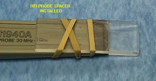
22 APPENDIX A PROBE SPACER 18
ENGINEERING COMMITTEE Interface Practices Subcommittee AMERICAN NATIONAL STANDARD ANSI/SCTE
 ENGINEERING COMMITTEE Interface Practices Subcommittee AMERICAN NATIONAL STANDARD ANSI/SCTE 145 2013 Test Method for Second Harmonic Distortion of ives Using a Single Carrier NOTICE The Society of Cable
SOCIETY OF CABLE TELECOMMUNICATIONS ENGINEERS INC
 SOCIETY OF CABLE TELECOMMUNICATIONS ENGINEERS INC ENGINEERING COMMITTEE Interface Practices Subcommittee AMERICAN NATIONAL STANDARD ANSI/SCTE 151 2008 Mechanical, Electrical, and Environmental Requirements
ENGINEERING COMMITTEE Interface Practices Subcommittee AMERICAN NATIONAL STANDARD ANSI/SCTE
 ENGINEERING COMMITTEE Interface Practices Subcommittee AMERICAN NATIONAL STANDARD ANSI/SCTE 126 2013 Test Method for Distortion of 2-way Amplifiers Caused by Insufficient Isolation of Built in Diplex Filter
ENGINEERING COMMITTEE Interface Practices Subcommittee AMERICAN NATIONAL STANDARD ANSI/SCTE Measurement Procedure for Noise Power Ratio
 ENGINEERING COMMITTEE Interface Practices Subcommittee AMERICAN NATIONAL STANDARD ANSI/SCTE 119 2006 Measurement Procedure for Noise Power Ratio NOTICE The Society of Cable Telecommunications Engineers
ENGINEERING COMMITTEE Interface Practices Subcommittee AMERICAN NATIONAL STANDARD ANSI/SCTE Test Method For Coaxial Cable Impedance
 ENGINEERING COMMITTEE Interface Practices Subcommittee AMERICAN NATIONAL STANDARD ANSI/SCTE 66 2008 Test Method For Coaxial Cable Impedance NOTICE The Society of Cable Telecommunications Engineers (SCTE)
AMERICAN NATIONAL STANDARD
 ENGINEERING COMMITTEE Interface Practices Subcommittee AMERICAN NATIONAL STANDARD ANSI/SCTE 151 2015 Mechanical, Electrical, and Environmental Requirements for RF Traps and Filters NOTICE The Society of
AMERICAN NATIONAL STANDARD
 Interface Practices Subcommittee AMERICAN NATIONAL STANDARD Measurement Procedure for Noise Power Ratio NOTICE The Society of Cable Telecommunications Engineers (SCTE) / International Society of Broadband
ENGINEERING COMMITTEE
 ENGINEERING COMMITTEE Interface Practices Subcommittee AMERICAN NATIONAL STANDARD ANSI/SCTE 45 2012 Test Method for Group Delay NOTICE The Society of Cable Telecommunications Engineers (SCTE) Standards
ENGINEERING COMMITTEE Interface Practices Subcommittee AMERICAN NATIONAL STANDARD ANSI/SCTE
 ENGINEERING COMMITTEE Interface Practices Subcommittee AMERICAN NATIONAL STANDARD ANSI/SCTE 115 2011 Test Method for Reverse Path (Upstream) Intermodulation Using Two Carriers NOTICE The Society of Cable
ENGINEERING COMMITTEE Interface Practices Subcommittee AMERICAN NATIONAL STANDARD ANSI/SCTE
 ENGINEERING COMMITTEE Interface Practices Subcommittee AMERICAN NATIONAL STANDARD ANSI/SCTE 82 2012 Test Method for Low Frequency and Spurious Disturbances NOTICE The Society of Cable Telecommunications
AMERICAN NATIONAL STANDARD
 ENGINEERING COMMITTEE Interface Practices Subcommittee AMERICAN NATIONAL STANDARD ANSI/SCTE 91 2015 Specification for 5/8-24 RF & AC Equipment Port, Female NOTICE The Society of Cable Telecommunications
AMERICAN NATIONAL STANDARD
 Interface Practices Subcommittee AMERICAN NATIONAL STANDARD ANSI/SCTE 78 2017 Test Method for Transfer Impedance NOTICE The Society of Cable Telecommunications Engineers (SCTE) / International Society
AMERICAN NATIONAL STANDARD
 ENGINEERING COMMITTEE Interface Practices Subcommittee AMERICAN NATIONAL STANDARD ANSI/SCTE 81 2007 Surge Withstand Test Procedure NOTICE The Society of Cable Telecommunications Engineers (SCTE) Standards
ENGINEERING COMMITTEE Interface Practices Subcommittee AMERICAN NATIONAL STANDARD ANSI/SCTE
 ENGINEERING COMMITTEE Interface Practices Subcommittee AMERICAN NATIONAL STANDARD ANSI/SCTE 108 2006 Test Method for Dielectric Withstand of Coaxial Cable NOTICE The Society of Cable Telecommunications
ENGINEERING COMMITTEE Interface Practices Subcommittee AMERICAN NATIONAL STANDARD ANSI/SCTE
 ENGINEERING COMMITTEE Interface Practices Subcommittee AMERICAN NATIONAL STANDARD ANSI/SCTE 177 2012 Specification for Braided 75 Ω, Mini-Series Quad Shield Coaxial Cable for CMTS and SDI cables NOTICE
ENGINEERING COMMITTEE Hybrid Management Sub-Layer Subcommittee AMERICAN NATIONAL STANDARD ANSI/SCTE
 ENGINEERING COMMITTEE Hybrid Management Sub-Layer Subcommittee AMERICAN NATIONAL STANDARD ANSI/SCTE 25-1 2008 Hybrid Fiber Coax Outside Plant Status Monitoring Physical (PHY) Layer Specification v1. NOTICE
ENGINEERING COMMITTEE Interface Practices Subcommittee SCTE Test Procedure for Hum Modulation
 ENGINEERING COMMITTEE Interface Practices Subcommittee SCTE 16 2012 Test Procedure for Hum Modulation NOTICE The Society of Cable Telecommunications Engineers (SCTE) Standards are intended to serve the
87415A microwave system amplifier A microwave. system amplifier A microwave system amplifier A microwave.
 20 Amplifiers 83020A microwave 875A microwave 8308A microwave 8307A microwave 83006A microwave 8705C preamplifier 8705B preamplifier 83050/5A microwave The Agilent 83006/07/08/020/050/05A test s offer
Microwave. Accessories for Microwave Scalar and System Analyzers
 Microwave Accessories for Microwave Scalar and System Analyzers The following optional accessories are designed for use with the 6200B series of Microwave Test Sets, the 6820 series Scalar Analyzers and
NOTICE. (Formulated under the cognizance of the CTA R4 Video Systems Committee.)
") ANSI/CTA Standard Antenna Control Interface ANSI/CTA-909-B (Formerly ANSI/) January 2011 NOTICE Consumer Technology Association (CTA) Standards, Bulletins and other technical publications are designed
ANSI/CTA Standard Antenna Control Interface ANSI/CTA-909-B (Formerly ANSI/) January 2011 NOTICE Consumer Technology Association (CTA) Standards, Bulletins and other technical publications are designed
User Manual CXE Rev (12) CXX Series. User Manual. Teleste Corporation. CXE880 Fibre node
 CXX Series. User Manual. Teleste Corporation. CXE880 Fibre node") 17.12.2012 1(12) CXX Series User Manual Teleste Corporation CXE880 Fibre node 17.12.2012 2(12) Contents Introduction... 3 Installation... 3 Housing... 3 Powering... 3 Status monitoring card (optional)...
17.12.2012 1(12) CXX Series User Manual Teleste Corporation CXE880 Fibre node 17.12.2012 2(12) Contents Introduction... 3 Installation... 3 Housing... 3 Powering... 3 Status monitoring card (optional)...
User Manual CXE Rev.002 Broadband Cable Networks March 3, (10) CXX Series. User Manual. Teleste Corporation CXE880.
 CXX Series. User Manual. Teleste Corporation CXE880.") Broadband Cable Networks March 3, 2008 1(10) CXX Series User Manual Teleste Corporation CXE880 Fibre Node Broadband Cable Networks March 3, 2008 2(10) Introduction The CXE880 is a fibre deep optical node
Broadband Cable Networks March 3, 2008 1(10) CXX Series User Manual Teleste Corporation CXE880 Fibre Node Broadband Cable Networks March 3, 2008 2(10) Introduction The CXE880 is a fibre deep optical node
Advanced Test Equipment Rentals ATEC (2832)
") Established 1981 Advanced Test Equipment Rentals www.atecorp.com 800-404-ATEC (2832) 6500 Series Loop Antennas User Manual ETS-Lindgren Inc. reserves the right to make changes to any product described
Established 1981 Advanced Test Equipment Rentals www.atecorp.com 800-404-ATEC (2832) 6500 Series Loop Antennas User Manual ETS-Lindgren Inc. reserves the right to make changes to any product described
Current Probes. User Manual
 Current Probes User Manual ETS-Lindgren Inc. reserves the right to make changes to any product described herein in order to improve function, design, or for any other reason. Nothing contained herein shall
Optiva OTS-2 40 GHz Amplified Microwave Band Fiber Optic Links
 5 MHz to 4 GHz Amplified Microwave Transport System The Optiva OTS-2 4 GHz Microwave Band transmitter and receiver are ideal to construct transparent fiber optic links in the 5 MHz to 4 GHz frequency range
Log Periodic Dipole Array Antenna
 Model 3148B Log Periodic Dipole Array Antenna User Manual ETS-Lindgren L.P. reserves the right to make changes to any product described herein in order to improve function, design, or for any other reason.
ECE 4670 Spring 2014 Lab 1 Linear System Characteristics
 ECE 4670 Spring 2014 Lab 1 Linear System Characteristics 1 Linear System Characteristics The first part of this experiment will serve as an introduction to the use of the spectrum analyzer in making absolute
NRSC-2 Emission Limitation for AM Broadcast Transmission June, 1988
 NRSC-2 Emission Limitation for AM Broadcast Transmission June, 1988 NOTICE NRSC Standards, Bulletins and other technical publications are designed to serve the public interest through eliminating misunderstandings
Contents. CALIBRATION PROCEDURE NI PXIe-5698
 CALIBRATION PROCEDURE NI PXIe-5698 This document contains the verification and adjustment procedures for the National Instruments PXIe-5698 (NI 5698). See ni.com/calibration for more information about
Optiva OTS-2 40 GHz Amplified Microwave Band Fiber Optic Links
 2 GHz to 4 GHz Amplified Microwave Transport System The Optiva OTS-2 4 GHz Microwave Band transmitter and receiver are ideal to construct transparent fiber optic links in the 5 MHz to 4 GHz frequency range
MODEL BLN GHz FIBER DEEP NODE STARLINE SERIES
 MODEL BLN100 1 1 GHz FIBER DEEP NODE STARLINE SERIES The BLN100 optical node is an essential building block in evolving Hybrid Fiber Coaxial (HFC) network architectures enabling amplifier to node conversions.
772D coaxial dual-directional coupler 773D coaxial directional coupler. 775D coaxial dual-directional coupler 776D coaxial dual-directional coupler
 72 772D coaxial dual-directional coupler 773D coaxial directional coupler 775D coaxial dual-directional coupler 776D coaxial dual-directional coupler 777D coaxial dual-directional coupler 778D coaxial
Optiva OTS-2 18 GHz Amplified Microwave Band Fiber Optic Links
 MHz to 18 GHz Amplified Microwave Transport System The Optiva OTS-2 18 GHz Microwave Band transmitter and receiver are ideal to construct transparent fiber optic links in the MHz to 18 GHz frequency range
Model 3725/2M. Line Impedance Stabilization Network (LISN) User Manual
 User Manual") Model 3725/2M Line Impedance Stabilization Network (LISN) User Manual ETS-Lindgren L.P. reserves the right to make changes to any product described herein in order to improve function, design, or for any
Model 3725/2M Line Impedance Stabilization Network (LISN) User Manual ETS-Lindgren L.P. reserves the right to make changes to any product described herein in order to improve function, design, or for any
This is a preview - click here to buy the full publication
 TECHNICAL REPORT IEC TR 63170 Edition 1.0 2018-08 colour inside Measurement procedure for the evaluation of power density related to human exposure to radio frequency fields from wireless communication
PXIe Contents. Required Software CALIBRATION PROCEDURE
 CALIBRATION PROCEDURE PXIe-5113 This document contains the verification and adjustment procedures for the PXIe-5113. Refer to ni.com/calibration for more information about calibration solutions. Contents
Circuit Characterization with the Agilent 8714 VNA
 Circuit Characterization with the Agilent 8714 VNA By: Larry Dunleavy Wireless and Microwave Instruments University of South Florida Objectives 1) To examine the concepts of reflection, phase shift, attenuation,
Advanced Test Equipment Rentals ATEC (2832)
") Established 1981 Advanced Test Equipment Rentals www.atecorp.com 800-404-ATEC (2832) A.H. Systems Model Active Monopole Antennas Active Monopole Antenna Series Operation Manual 1 TABLE OF CONTENTS INTRODUCTION
Established 1981 Advanced Test Equipment Rentals www.atecorp.com 800-404-ATEC (2832) A.H. Systems Model Active Monopole Antennas Active Monopole Antenna Series Operation Manual 1 TABLE OF CONTENTS INTRODUCTION
NATIONAL RADIO SYSTEMS COMMITTEE
 NRSC STANDARD NATIONAL RADIO SYSTEMS COMMITTEE NRSC-2-A Emission Limitation for Analog AM Broadcast Transmission September, 2007 NAB: 1771 N Street, N.W. CEA: 1919 South Eads Street Washington, DC 20036
MICROWAVE MICROWAVE TRAINING BENCH COMPONENT SPECIFICATIONS:
 Microwave section consists of Basic Microwave Training Bench, Advance Microwave Training Bench and Microwave Communication Training System. Microwave Training System is used to study all the concepts of
Keysight Technologies Differences in Application Between Power Dividers and Power Splitters. Application Note
 Keysight Technologies Differences in Application Between Dividers and Splitters Application Note 02 Keysight Differences in Application Between Dividers and Splitters Application Note Introduction dividers
Demo / Application Guide for DSA815(-TG) / DSA1000 Series
 / DSA1000 Series") Demo / Application Guide for DSA815(-TG) / DSA1000 Series TX1000 Mobile Phone Frontend Mixer Bandpass Filter PA The schematic above shows a typical front end of a mobile phone. Our TX1000 RF Demo Kit shows
Demo / Application Guide for DSA815(-TG) / DSA1000 Series TX1000 Mobile Phone Frontend Mixer Bandpass Filter PA The schematic above shows a typical front end of a mobile phone. Our TX1000 RF Demo Kit shows
Matric Limited Hill City Road R.R. #1 Box 421A Seneca, PA 16346
 FCC CERTIFICATION TEST REPORT for Hill City Road R.R. #1 Box 421A Seneca, PA 16346 FCC ID: K5B-TP105 May 14, 2001 Revised: June 18, 2001 WLL PROJECT #: 6182X This report may not be reproduced, except in
Screening Attenuation of Long Cables
 Screening Attenuation of Long Cables Carl W. Dole, John W. Kincaid Belden Electronics Division Richmond, Indiana Abstract The characteristics of a triaxial test fixture, which has been developed for screening
Ave output power ANT 1(dBm) Ave output power ANT 2 (dbm)
 Ave output power ANT 2 (dbm)") Page 41 of 103 9.6. Test Result The test was performed with 802.11b Channel Frequency (MHz) power ANT 1(dBm) power ANT 2 (dbm) power ANT 1(mW) power ANT 2 (mw) Limits dbm / W Low 2412 7.20 7.37 5.248 5.458
Page 41 of 103 9.6. Test Result The test was performed with 802.11b Channel Frequency (MHz) power ANT 1(dBm) power ANT 2 (dbm) power ANT 1(mW) power ANT 2 (mw) Limits dbm / W Low 2412 7.20 7.37 5.248 5.458
NON-AMPLIFIED HIGH SPEED PHOTODETECTOR USER S GUIDE
 NON-AMPLIFIED HIGH SPEED PHOTODETECTOR USER S GUIDE Thank you for purchasing your Non-amplified High Speed Photodetector. This user s guide will help answer any questions you may have regarding the safe
Spectrum Analyzers 2680 Series Features & benefits
 Data Sheet Features & benefits n Frequency range: 9 khz to 2.1 or 3.2 GHz n High Sensitivity -161 dbm/hz displayed average noise level (DANL) n Low phase noise of -98 dbc/hz @ 10 khz offset n Low level
Model BiConiLog Antenna. User Manual
 Model 3149 BiConiLog Antenna User Manual ETS-Lindgren Inc. reserves the right to make changes to any products herein to improve functioning or design. Although the information in this document has been
Compact Model Fiber Deep Node 862 MHz with 42/54 MHz Split
 Optoelectronics Compact Model 90090 Fiber Deep Node 862 MHz with 42/54 MHz Split Description The Scientific-Atlanta Compact Model 90090 Fiber Deep Node is a small, low-cost, 110V AC powered node that addresses
AMERICAN NATIONAL STANDARD
 Interface Practices Subcommittee AMERICAN NATIONAL STANDARD Test Procedure for Hum Modulation NOTICE The Society of Cable Telecommunications Engineers (SCTE) Standards and Operational Practices (hereafter
HP 86290B RF PLUG-IN GHz HEWLETT PACKARD
 OPERATING AND SERVICE MANUAL. HP 86290B RF PLUG-IN 2.0-18.6 GHz HEWLETT PACKARD COPYRIGHT AND DISCLAIMER NOTICE Copyright - Agilent Technologies, Inc. Reproduced with the permission of Agilent Technologies
Copyright Teletronics International, Inc. Patent Pending
 Copyright 2003 By Teletronics International, Inc. Patent Pending FCC NOTICES Electronic Emission Notice: This device complies with Part 15 of the FCC rules. Operation is subject to the following two conditions:
TELESTE AC NODE SPECIFIC MODULES
 TELESTE AC NODE SPECIFIC MODULES AC 6310 Power supply module for Teleste AC8000 and AC8800 optical nodes. Can work alone or it can be operated parallel to split the work load and create the redundancy
10 GHz Microwave Link
 10 GHz Microwave Link Project Project Objectives System System Functionality Testing Testing Procedures Cautions and Warnings Problems Encountered Recommendations Conclusion PROJECT OBJECTIVES Implement
Model 3180B Mini-Bicon Antenna User Manual
 Model 3180B Mini-Bicon Antenna User Manual Model 3180B with conical elements Model 3180B with cage elements ETS-Lindgren L.P. reserves the right to make changes to any product described herein in order
SAS-563B Active Loop Antenna Operation Manual
 SAS-563B Active Loop Antenna Operation Manual 1 TABLE OF CONTENTS INTRODUCTION 3 SPECIFICATIONS 5 OPERATING INSTRUCTIONS 7 CALCULATIONS 11 ANTENNA FORMULAS 12 MAINTENANCE 13 WARRANTY 14 2 INTRODUCTION
SAS-562B Active Loop Antenna Operation Manual
 SAS-562B Active Loop Antenna Operation Manual 1 TABLE OF CONTENTS INTRODUCTION 3 SPECIFICATIONS 5 OPERATING INSTRUCTIONS 7 CALCULATIONS 11 ANTENNA FORMULAS 12 MAINTENANCE 13 WARRANTY 14 2 INTRODUCTION
ECC Recommendation (16)04
04") ECC Recommendation (16)04 Determination of the radiated power from FM sound broadcasting stations through field strength measurements in the frequency band 87.5 to 108 MHz Approved 17 October 2016 Edition
ECC Recommendation (16)04 Determination of the radiated power from FM sound broadcasting stations through field strength measurements in the frequency band 87.5 to 108 MHz Approved 17 October 2016 Edition
rf link 870 mhz mini-bridger
 application ANTEC s 870 MHz Mini-Bridger is deployed in the RF network as either a two or three output device. The Mini-Bridger provides a flexible high gain and high level PHD platform that is cost-effective
BDA Broadband Drop Amplifier
 BDA Broadband Drop Amplifier FEATURES 1 GHz Gallium Arsenide Technology 2.5 db Noise Figure Patented Auto Seize FFT F Connector One, Two, or Four Port Versions Two Way Capable LED Power Verification Local
Application Note: Swept Return Loss & VSWR Antenna Measurements using the Eagle Technologies RF Bridge
 : Swept Return Loss & VSWR Antenna Measurements using the Eagle Technologies RF Bridge FCT-1008A Introduction Return loss and VSWR are a measure of the magnitude of a transmitted RF Signal in relation
Diamond Line Type 1 and Type 2 Amplifiers
 TM Diamond Line Type 1 and Type 2 Amplifiers Reference & Installation Manual Part Number: 2244001 Rev. D 06/03 Diamond Line Series Type 1 and Type 2 Amplifiers Reference and Installation Manual 2244001
INTERNATIONAL STANDARD
 INTERNATIONAL STANDARD IEC 61726 Second edition 1999-11 Cable assemblies, cables, connectors and passive microwave components Screening attenuation measurement by the reverberation chamber method Câbles,
Compact Nodes and 90071
 Fiber ptics Compact Nodes 90070 and 90071 Dedicated ptimized Nodes The 90070 receiver node is designed for long distance trunk applications to feed architectures of any density. Dual output with enhanced
Model 3140B BiConiLog Antenna User Manual
 Model 3140B BiConiLog Antenna User Manual Model 3140B mounted onto a 7-TR tripod (not included) ETS-Lindgren L.P. reserves the right to make changes to any product described herein in order to improve
750 MHz Magnamax series
 750 MHz Magnamax series MLE3007RMLE Magnamax Line Extender (Legacy RMLE style) Description: The 750 MHz Magnamax series broadband line extender is essentially a drop-in-upgrade module that allows the customer
OPEN TEM CELLS FOR EMC PRE-COMPLIANCE TESTING
 1 Introduction Radiated emission tests are typically carried out in anechoic chambers, using antennas to pick up the radiated signals. Due to bandwidth limitations, several antennas are required to cover
New Ultra-Fast Noise Parameter System... Opening A New Realm of Possibilities in Noise Characterization
 New Ultra-Fast Noise Parameter System... Opening A New Realm of Possibilities in Noise Characterization David Ballo Application Development Engineer Agilent Technologies Gary Simpson Chief Technology Officer
Swept Return Loss & VSWR Antenna Measurements using the Eagle Technologies RF Bridge
 Swept Return Loss & VSWR Antenna Measurements using the Eagle Technologies RF Bridge April, 2015 Page 1 of 7 Introduction Return loss and VSWR are a measure of the magnitude of a transmitted RF Signal
8370 Court Avenue, Suite B-1 Ellicott City, Maryland (410) FCC CERTIFICATION
 FCC CERTIFICATION") IKUSI FCC INFORMATION RF Measurement Report Prepared by:: National Certification Laboratory 8370 Court Avenue, Suite B-1 Ellicott City, Maryland 21043 (410) 461-5548 IIn Supportt off:: FCC CERTIFICATION
IKUSI FCC INFORMATION RF Measurement Report Prepared by:: National Certification Laboratory 8370 Court Avenue, Suite B-1 Ellicott City, Maryland 21043 (410) 461-5548 IIn Supportt off:: FCC CERTIFICATION
The Precision Spherical Dipole Source
 The Precision Spherical Dipole Source Freedom to make accurate and repeatable measurements!! Presented by: Bruce Archambeault, Ph.D. Partner / Technical Director bruce@appliedemtech.com (AET) Mission:
EIA STANDARD TP-27B. Mechanical Shock (Specified Pulse) Test Procedure for Electrical Connectors EIA B ELECTRONIC INDUSTRIES ASSOCIATION
 Test Procedure for Electrical Connectors EIA B ELECTRONIC INDUSTRIES ASSOCIATION") ANSI/-1996 Approved: April 17, 1996 EIA STANDARD TP-27B Mechanical Shock (Specified Pulse) Test Procedure for Electrical Connectors (Revision of EIA-364-27A) MAY 1996 ELECTRONIC INDUSTRIES ASSOCIATION
ANSI/-1996 Approved: April 17, 1996 EIA STANDARD TP-27B Mechanical Shock (Specified Pulse) Test Procedure for Electrical Connectors (Revision of EIA-364-27A) MAY 1996 ELECTRONIC INDUSTRIES ASSOCIATION
Bill Ham Martin Ogbuokiri. This clause specifies the electrical performance requirements for shielded and unshielded cables.
 098-219r2 Prepared by: Ed Armstrong Zane Daggett Bill Ham Martin Ogbuokiri Date: 07-24-98 Revised: 09-29-98 Revised again: 10-14-98 Revised again: 12-2-98 Revised again: 01-18-99 1. REQUIREMENTS FOR SPI-3
BluePhase 1000 PHASE NOISE TEST SYSTEM. Operations Manual
 BluePhase 1000 PHASE NOISE TEST SYSTEM Operations Manual WENZEL ASSOCIATES, INC. 2215 Kramer Lane Austin, TX 78758 USA 512-835-2038 fax 512-719-4086 http://www.wenzel.com e-mail: sales@wenzel.com Table
Contents. CALIBRATION PROCEDURE NI PXIe-5668R 14 GHz and 26.5 GHz Signal Analyzer
 CALIBRATION PROCEDURE NI PXIe-5668R 14 GHz and 26.5 GHz Signal Analyzer This document contains the verification procedures for the National Instruments PXIe-5668R (NI 5668R) vector signal analyzer (VSA)
SWR/Return Loss Measurements Using System IIA
 THE GLOBAL SOURCE FOR PROVEN TEST SWR/Return Loss Measurements Using System IIA SWR/Return Loss Defined Both SWR and Return Loss are a measure of the divergence of a microwave device from a perfect impedance
product note Using Power Leveling to Control Test Port Output Power Product Note 8510XF XF Network Analyzer
 This literature was published years prior to the establishment of Agilent Technologies as a company independent from Hewlett-Packard and describes products or services now available through Agilent. It
Shielding Effectiveness Report HQDP
 HQDP Mates with QSH-DP, QTH-DP Description: 0.50mm 100Ω Differential 30 AWG Twinax Cable Assembly Samtec, Inc. 2005 All Rights Reserved Table of Contents Product Overview... 1 Test Overview... 1 Shielded
A Noise-Temperature Measurement System Using a Cryogenic Attenuator
 TMO Progress Report 42-135 November 15, 1998 A Noise-Temperature Measurement System Using a Cryogenic Attenuator J. E. Fernandez 1 This article describes a method to obtain accurate and repeatable input
TELESTE AC AMPLIFIER MODULES
 TELESTE AC AMPLIFIER MODULES AC 6110 INPUT MODULE AC6110 is an input module with 0 db attenuation. Supports frequencies up to 1.2 GHz. 0 db jumper module to be used as an input module in AC-amplifier platform
This is a preview - click here to buy the full publication INTERNATIONAL ELECTROTECHNICAL COMMISSION
 INTERNATIONAL ELECTROTECHNICAL COMMISSION CISPR 22 Fifth edition 2005-04 INTERNATIONAL SPECIAL COMMITTEE ON RADIO INTERFERENCE Information technology equipment Radio disturbance characteristics Limits
Diamond Line 3 Single Output Amplifiers
 Diamond Line 3 Single Output Amplifiers About this Section In this section, you will find the following reference information about the Diamond Line 3 single output amplifiers: Item...Page Equipment Description...9
Model 6942 Four Port Optoelectronic Node 870 MHz with 42/54 MHz Split
 Optoelectronics Model 6942 Four ort Optoelectronic Node 870 MHz with 42/54 MHz Split Description The Model 6942 Node is a high performance, four output optoelectronic node. The Model 6942 Node can be configured
OPEN TEM CELLS FOR EMC PRE-COMPLIANCE TESTING
 1 Introduction Radiated emission tests are typically carried out in anechoic chambers, using antennas to pick up the radiated signals. Due to bandwidth limitations, several antennas are required to cover
TIA-527 Balanced Optical/Electrical Converter. Operating Instructions
 TIA-527 Balanced Optical/Electrical Converter Operating Instructions Terahertz Technologies Inc.169 Clear Road Oriskany NY 13424 (315) 736-3642 FAX (315) 736-4078 E-mail sales@terahertztechnologies.com
DSA700 Series Spectrum Analyzer
 DSA700 Series Spectrum Analyzer Product Features: All-Digital IF Technology Frequency Range from 100 khz up to 1 GHz Min. -155 dbm Displayed Average Noise Level (Typ.) Min.
Contents. 1 Introduction. 2 System-Level Electrostatic Discharge (ESD) and Electrical Fast Transient. 3 Electromagnetic Interference
 and Electrical Fast Transient. 3 Electromagnetic Interference") Issue 3, October 2002 Electromagnetic Compatibility and Electrical Safety Contents Telcordia GR-1089 - Documentation Information Generic Requirements Notice Of Disclaimer................. iii Contents.......................................
Issue 3, October 2002 Electromagnetic Compatibility and Electrical Safety Contents Telcordia GR-1089 - Documentation Information Generic Requirements Notice Of Disclaimer................. iii Contents.......................................
Agilent X-Series Signal Analyzer This manual provides documentation for the following X-Series Analyzer: CXA Signal Analyzer N9000A
 Agilent X-Series Signal Analyzer This manual provides documentation for the following X-Series Analyzer: CXA Signal Analyzer N9000A N9000A CXA Functional Tests Notices Agilent Technologies, Inc. 2006-2008
Microwave Circuit Design and Measurements Lab. INTRODUCTION TO MICROWAVE MEASUREMENTS: DETECTION OF RF POWER AND STANDING WAVES Lab #2
 EE 458/558 Microwave Circuit Design and Measurements Lab INTRODUCTION TO MICROWAVE MEASUREMENTS: DETECTION OF RF POWER AND STANDING WAVES Lab #2 The purpose of this lab is to gain a basic understanding
NON-AMPLIFIED PHOTODETECTOR USER S GUIDE
 NON-AMPLIFIED PHOTODETECTOR USER S GUIDE Thank you for purchasing your Non-amplified Photodetector. This user s guide will help answer any questions you may have regarding the safe use and optimal operation
Model 6940 Four Port Optoelectronic Node 870 MHz with 42/54 MHz Split
 Optoelectronics Model 6940 Four ort Optoelectronic Node 870 MHz with 42/54 MHz Split Description The Model 6940 Node is a high performance, four output optoelectronic node. The Model 6940 Node can be configured
EFFECT OF SHIELDING ON CABLE RF INGRESS MEASUREMENTS LARRY COHEN
 EFFECT OF SHIELDING ON CABLE RF INGRESS MEASUREMENTS LARRY COHEN OVERVIEW Purpose: Examine the common-mode and differential RF ingress levels of 4-pair UTP, F/UTP, and F/FTP cables at an (RJ45) MDI port
Broadband System - J
 Broadband System - J Satellites are spaced every 2nd degrees above earth "C" Band Toward satellite 6.0 GHz Toward earth 4.0 GHz "L" Band Toward satellite 14.0 GHz Toward earth 12.0 GHz TV TRANSMITTER Headend
Comparison of IC Conducted Emission Measurement Methods
 IEEE TRANSACTIONS ON INSTRUMENTATION AND MEASUREMENT, VOL. 52, NO. 3, JUNE 2003 839 Comparison of IC Conducted Emission Measurement Methods Franco Fiori, Member, IEEE, and Francesco Musolino, Member, IEEE
BDA Broadband Drop Amplifier
 BDA Broadband Drop Amplifier FEATURES 1 GHz Gallium Arsenide Technology 2.5 db Noise Figure Patented Auto Seize FFT P Series F Connector One, Two, or Four Port Versions Two Way Capable LED Power Verification
Documentation. PerfectPulse Fast Edge Signal Generator
 PerfectPulse Fast Edge Signal Generator Documentation Version 1.1, 2018 Copyright 2018 Picotest and PMK Mess- und Kommunikationstechnik GmbH All Rights Reserved Trademarks The Picotest logo is a trademark
Calibrating the NI 5653 requires you to install one of the following packages on the calibration system. NI-RFSA 2.4 or later NI-RFSG 1.
 CALIBRATION PROCEDURE NI PXIe-5653 This document contains the verification and adjustment procedures for the National Instruments PXIe-5653 RF synthesizer (NI 5653). Refer to ni.com/calibration for more
Contents. Software Requirements. CALIBRATION PROCEDURE NI PXIe-5663E
 CALIBRATION PROCEDURE NI PXIe-5663E This document contains instructions for writing a manual calibration procedure for the NI PXIe-5663E (NI 5663E) RF vector signal analyzer. For more information about
Measuring Photonic, Optoelectronic and Electro optic S parameters using an advanced photonic module
 Measuring Photonic, Optoelectronic and Electro optic S parameters using an advanced photonic module APPLICATION NOTE This application note describes the procedure for electro-optic measurements of both
ISO INTERNATIONAL STANDARD. Non-destructive testing Ultrasonic inspection Evaluating electronic characteristics of ultrasonic test instruments
 INTERNATIONAL STANDARD ISO 12710 First edition 2002-09-15 Non-destructive testing Ultrasonic inspection Evaluating electronic characteristics of ultrasonic test instruments Essais non destructifs Contrôle