Norfolk Amateur Radio Club
|
|
|
- Merry Tucker
- 5 years ago
- Views:
Transcription
1 Norfolk Amateur Radio Club The Transmitter & Transmitter Interference Nick M0HGU & Steve G3PND
2 Plan for the Day The Transmitter Introduction, Block diagrams Oscillators, Buffers & Multipliers Modulation Mixing (up), PAs, ALC & SWR Transmitter Interference Stability & Drift Unwanted emissions Operator faults Harmonics RF or AF?
3 The Transmitter We are revising & extending the intermediate material What does a transmitter need to do? Create an RF signal inside the amateur band For the signal to be nice and clean For the signal to be stable For the signal to have minimum band width for the type of transmission For the signal to have the correct power output For the transmitter to have minimum output on other frequencies
4 The block diagram An SSB transmitter using mixers to generate the final RF (though it is common now for the modulator to be switchable to generate AM, SSB or FM)
5 The block diagram A FM transmitter using frequency multipliers to generate the final RF
6 Oscillators Steve G3PND
7 Modulation We need to look at the following: AM SSB FM Digital
8 Modulation types You will remember from intermediate (and foundation) the two basic types of modulation:
9 AM Amplitude Modulation: Generated by mixing the Audio Frequency & either Radio Frequency or Intermediate Frequency in an un-balanced

10 AM The unbalanced mixer produces all 4 mixing products at it s output
11 AM or single balanced mixer
12 AM The single balanced mixer produces Only 3 of the possible outputs and is configured to include the carrier (usually)

13 AM The Modulation Depth indicates how modulated the carrier is, more modulation results is a louder received audio. When m=1 the carrier is doubled on the peaks and 0 in the troughs M>1 = distortion Aim for m=0.8 m=0.9
14 AM When m=1 the amplitude of each sideband is exactly half the carrier amplitude.
15 SSB Here we don t want the carrier nor one of the side bands (USB or LSB) and a double balanced mixer is used.
16 SSB The unwanted sideband is removed by a filter, the carrier is suppressed by the DBM. We do not need both sidebands as they contain the same information So saving bandwidth, & power, one sideband cannot exceed ¼ the power of the carrier (see AM)
17 SSB/AM If a DC offset is applied to the RF input of the DBM then the carrier will not be rejected and an AM signal will result.
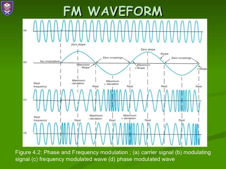
18 FM Remember the amplitude of the FM signal is constant and the frequency changes with the amplitude of the audio input. This can be done in two ways Changing the frequency of the oscillator Changing the phase of the oscillator output
19 FM A colpitts oscillator and be pushed & pulled
20 FM By applying the audio to the buffer after the oscillator it is possible arrange to change the instantaneous phase of the signal, this has the same effect as changing it s frequency. (not to be confused with Phase shift keying see later)
21
22 FM Peak deviation: Is the maximum amount that the frequency may vary - there is no theoretical limit but FM entertainment is limited to 75KHz Amateur are either 5KHz or 2.5KHz Deviation Ratio:
23 FM Modulation Index Is the ratio of Peak Deviation to Max Audio Frequency e.g. VHF FM Broadcasts 75KHz/15KHz = 5 This is Wide Band FM MI>1 e.g. Amateur 2M 2.5KHz/3KHz = 0.8 This is Narrow Band FM MI<1
24 FM Bandwidth Mathematically it can be argued to be infinite
25 FM The sidebands extend beyond the Peak Deviation, increasing the PD just means more of the sidebands have significant power, it will not alter the separation of the bands (if a single tone is used). Real audio is a range of tones and the spectrum will be continuous A general rule is Carson s Rule: Bandwidth = 2 * (Max Audio Freq. + Peak Deviation)
26 FM Carson s Rule: e.g Amateur 70cm transmission 2*(3KHz+5KHz) = 16KHz hence 25KHz channel separation At VHF 2*(2.8KHz+2.5KHz) = KHz channels are used
27 CW Carrier Wave or Morse Code Can be thought of as AM with a modulation depth of 10% There will be sidebands, these depend on speed and shape of the keying A fast rise time will cause sidebands several KHz wide think of the square wave keying as having many high frequency components modulating the AM signal
28 CW A rise time of around 5ms is considered a good compromise between readability and suppression of key clicks. A small R/C filter can be used to achieve this, or much more sophisticated methods can be devised.


29 Key Clicks Key clicks evident Clean signal
30 Data Early data was RTTY, using a 5bit code, followed by PSK31, MFSK16, Packet etc. There are three ways to Tx data Data is converted to audio tones which are sent to a FM transmitter Data is converted to audio tones which are sent to an SSB transmitter Directly modulating the carrier
 is present and the bandwidth is determined by the highest audio tone and the peak")
31 Data On FM, the carrier is modulated by one or more audio tones This is Audio Frequency Shift Keying, be aware that there will be a carrier even when no data (audio sub carrier) is present and the bandwidth is determined by the highest audio tone and the peak deviation
32 Data AFSK spectrum (7.002MHz carrier RTTY & KHz)
33 Data If we feed the data directly into the FM modulator (varicap diode in a modified colpitts oscillator) here we do not convert to audio and the bandwidth is small. This is FSK (7.002MHz carrier RTTY & KHz)
34 Data If we feed the tones used to modulate our FM signal above into an SSB transmitter the result is identical to that of FSK (7.002MHz carrier RTTY & KHz)


35 PSK Not in the syllabus but Binary Phase Shift Keying (at 31 baud)
36 Emission codes AFSK on FM is F2B F = FM 2 = Audio sub carrier B = Data for automatic reception FSK is F1B 1 = digital signals with no sub carrier SSB AFSK is J2B J= SSB
37 Mixing up, Pas, ALC & SWR Steve G3PND
38 Transmitter Interference Stability & drift You will remember from earlier that we need our Tx to: Create an RF signal inside the amateur band For the signal to be nice and clean For the signal to be stable
39 Stability & Drift Drift is where the (or one of the) master oscillators changes frequency over a period of time. There are several possible causes: Temperature change Supply voltage change Change to output loading / stray capacitances Mechanical shock Ageing
40 Temperature The temperature can affect inductance and capacitance in tuned circuits all transmitters warm up usually 30 minutes or so is enough Long overs (especially high duty cycle ones like data) can have an effect. It is possible to mix +ve & -ve temperature coefficient components to get close 0 temperature drift
41 Temperature
42 Supply Voltage/Chirp Supply voltage can affect the capacitance of active devices Use a separate, isolated, regulated supply for master oscillators Keep oscillators & buffers powered continuously
43 Output Loading A change in loading can pull an oscillator, a buffer amp will help as it isolated the oscillator from the load Stray capacitance, a hand, can also pull the frequency of an oscillator, screening with a tin can will avoid this (and spillage into other circuits) along with insulated couplings on controls
44 Mechanical shock Loose free wound inductors will move if knocked and so change their value. Always use stout connections, if te coil is on;y 2-3 turns and made with thick wire they should be OK. Capacitors should be high quality and again robustly connected
45 Ageing This is more an effect of crystals. The specification is given by the manufacturer in ppm (parts per million) e.g. a crystal with 5ppm initial accuracy and 10ppm/yr could be up to 15ppm off by the end of the first year so if 10MHz, it may be 150Hz off frequency
46 Stability & Drift Keep oscillators away from sources of heat the PA Ensure voltage supplies to oscillators are stable & well decoupled Screen sensitive sections to prevent stray capacitance effects and leakage of signals into or our of the circuit Buffer oscillators to reduce loading effects Use robust construction to reduce mechanical effects Allow for ageing od crystals by providing trimmer capacitors Use high quality components & construction methods
47 Unwanted Emissions etc. Steve G3PND
Technician License Course Chapter 2. Lesson Plan Module 3 Modulation and Bandwidth
 Technician License Course Chapter 2 Lesson Plan Module 3 Modulation and Bandwidth The Basic Radio Station What Happens During Radio Communication? Transmitting (sending a signal): Information (voice, data,
The G4EGQ RAE COURSE Lesson 9 Transmitters Lesson 8 looked at a simple transmitter exciter comprising of oscillator, buffer and multiplier stages.
 Lesson 8 looked at a simple transmitter exciter comprising of oscillator, buffer and multiplier stages. The power amplifier The output from the exciter is usually very low and it is necessary to amplify
4/29/2012. General Class Element 3 Course Presentation. Signals and Emissions. SignalSignals and Emissionsissions. Subelement G8
 General Class Element 3 Course Presentation ti ELEMENT 3 SUB ELEMENTS General Licensing Class Subelement G8 Signals and Emissions 2 Exam Questions, 2 Groups G1 Commission s Rules G2 Operating Procedures
Amplitude Modulated Systems
 Amplitude Modulated Systems Communication is process of establishing connection between two points for information exchange. Channel refers to medium through which message travels e.g. wires, links, or
Technician License Course Chapter 2. Lesson Plan Module 2 Radio Signals and Waves
 Technician License Course Chapter 2 Lesson Plan Module 2 Radio Signals and Waves The Basic Radio Station What Happens During Radio Communication? Transmitting (sending a signal): Information (voice, data,
HF Receivers, Part 2
 HF Receivers, Part 2 Superhet building blocks: AM, SSB/CW, FM receivers Adam Farson VA7OJ View an excellent tutorial on receivers NSARC HF Operators HF Receivers 2 1 The RF Amplifier (Preamp)! Typical
Test Equipment. PHYS 401 Physics of Ham Radio
 Test Equipment Voltmeter - an instrument that is used to measure voltage. It is used in parallel with a circuit to be measured. a series resistor extends the range of the meter. Ammeter - an instrument
Lesson 2 HF Procedures and Practices Overview
 Lesson 2 HF Procedures and Practices Overview On Display QSL Cards On Display Icom IC-7000 On Display Buxcomm Rascal Sound card interface: PSK31 SSTV RTTY Packet Digital Voice MFSK16 -more- Operating Techniques
General Class License Theory II. Dick Grote K6PBF
 General Class License Theory II Dick Grote K6PBF k6pbfdick@gmail.com 1 Introduction In the first theory class we talked about basic electrical principles and components. Now we will build on this to learn
KWM-2/2A Transceiver THE COLLINS KWM-2/2A TRANSCEIVER
 KWM-2/2A Transceiver Click the photo to see a larger photo Click "Back" button on browser to return Courtesy of Norm - WA3KEY THE COLLINS KWM-2/2A TRANSCEIVER Unmatched for versatility, dependability and
Module 8 Theory. dbs AM Detector Ring Modulator Receiver Chain. Functional Blocks Parameters. IRTS Region 4
 Module 8 Theory dbs AM Detector Ring Modulator Receiver Chain Functional Blocks Parameters Decibel (db) The term db or decibel is a relative unit of measurement used frequently in electronic communications
Technician License Course Chapter 3 Types of Radios and Radio Circuits. Module 7
 Technician License Course Chapter 3 Types of Radios and Radio Circuits Module 7 Radio Block Diagrams Radio Circuits can be shown as functional blocks connected together. Knowing the description of common
Amateur Wireless Station Operators License Exam
 Amateur Wireless Station Operators License Exam Study material 2017 South India Amateur Radio Society, Chennai CHAPTER 5 1 Chapter 5 Amateur Wireless Station Operators License Exam Study Material Chapter
Elmer Session Hand Out for 3/3/11 de W6WTI. Some Common Controls Found On Amateur Radio Transceivers. (From ARRL web site tutorial)
") Elmer Session Hand Out for 3/3/11 de W6WTI Some Common Controls Found On Amateur Radio Transceivers. (From ARRL web site tutorial) The placement of the controls may vary from manufacturer to manufacturer
Elmer Session Hand Out for 3/3/11 de W6WTI Some Common Controls Found On Amateur Radio Transceivers. (From ARRL web site tutorial) The placement of the controls may vary from manufacturer to manufacturer
Ham Radio Training. Level 1 Technician Level. Presented by Richard Bosch KJ4WBB
 Ham Radio Training Level 1 Technician Level Presented by Richard Bosch KJ4WBB In this chapter, you ll learn about: What is a radio signal The characteristics of radio signals How modulation adds information
Radio Receivers. Al Penney VO1NO
 Radio Receivers Al Penney VO1NO Role of the Receiver The Antenna must capture the radio wave. The desired frequency must be selected from all the EM waves captured by the antenna. The selected signal is
Barrett 950 HF transceiver specifications Using measurement methods described in European Telecommunication Standard
 Barrett 950 HF transceiver specifications Using measurement methods described in European Telecommunication Standard 300 373. General Specifications Equipment Standards Transmit frequency range Receive
Second Hand Yaesu FTDX5000MP HF base station transceiver
 263 Walsall Road, Great Wyrley, Walsall, WS6 6DL Established 1997. Open Monday - Friday 9am - 5pm and Saturday 9.30am - 4pm Tel: 01922 414 796 Fax: 01922 417829 Skype: radioworld_uk Second Hand Yaesu FTDX5000MP
Radio Receivers. Al Penney VO1NO
 Radio Receivers Role of the Receiver The Antenna must capture the radio wave. The desired frequency must be selected from all the EM waves captured by the antenna. The selected signal is usually very weak
Using measurement methods described in Australian/New Zealand Standard AS/NZS 4770:2000
 Barrett 2050 HF transceiver Using measurement methods described in Australian/New Zealand Standard AS/NZS 4770:2000 General Specifications Equipment Standards Transmit frequency range Receive frequency
Department of Examination, Sri Lanka
 Department of Examination, Sri Lanka EXAMINATION FOR THE AMATEUR RADIO OPERATORS CERTIFICATE OF PROFICIENCY ISSUED BY THE DIRECTOR GENERAL OF TELECOMMUNICATION OF SRI LANKA 2000 (GENERAL CLASS) Answer
Technician Licensing Class. Lesson 4. presented by the Arlington Radio Public Service Club Arlington County, Virginia
 Technician Licensing Class Lesson 4 presented by the Arlington Radio Public Service Club Arlington County, Virginia 1 Quiz Sub elements T6 & T7 2 Good Engineering Practice Sub element T8 3 A Basic Station
Technician License Course Chapter 5. Lesson Plan Module 11 Transmitters, Receivers and Transceivers
 Technician License Course Chapter 5 Lesson Plan Module 11 Transmitters, Receivers and Transceivers Generalized Transceiver Categories Mobile Single Band Dual Band All Band Multimode Handheld (HT) VHF/UHF
Modulation Methods Frequency Modulation
 Modulation Methods Frequency Modulation William Sheets K2MQJ Rudolf F. Graf KA2CWL The use of frequency modulation (called FM) is another method of adding intelligence to a carrier signal. While simple
Interference & Suppression Page 59
 INTERFERENCE Interference & Suppression Page 59 Front-End Overload, Cross-Modulation What is meant by receiver overload? Interference caused by strong signals from a nearby transmitter What is one way
3000 Hz. Average Noise
 PSK-31 Dave, K6AIX ddanner@earthlink.net 01-21-2007, 2007, D. H. Danner 1 What is PSK-31? Digital Text, ASCII Narrow Bandwidth, PSK, 31 Hz Low Power, < 25 watts Out Performs Teletype, Packet Low Cost,
FREQUENCY AGILE FM MODULATOR INSTRUCTION BOOK IB
 FMT615C FREQUENCY AGILE FM MODULATOR INSTRUCTION BOOK IB1215-02 TABLE OF CONTENTS SECTION SUBJECT 1.0 Introduction 2.0 Installation & Operating Instructions 3.0 Specification 4.0 Functional Description
Overview of NBEMS modes using FLDIGI
 Overview of NBEMS modes using FLDIGI K3EUI Barry Overview K3EUI - know your subject/subjects Digi Modes - can you identify them by sound Hardware needed to receive / transmit Modulation basics: AM, FM,
Chapter 3. Amplitude Modulation Fundamentals
 Chapter 3 Amplitude Modulation Fundamentals Topics Covered 3-1: AM Concepts 3-2: Modulation Index and Percentage of Modulation 3-3: Sidebands and the Frequency Domain 3-4: AM Power 3-5: Single-Sideband
LBI-30398N. MAINTENANCE MANUAL MHz PHASE LOCK LOOP EXCITER 19D423249G1 & G2 DESCRIPTION TABLE OF CONTENTS. Page. DESCRIPTION...
 MAINTENANCE MANUAL 138-174 MHz PHASE LOCK LOOP EXCITER 19D423249G1 & G2 LBI-30398N TABLE OF CONTENTS DESCRIPTION...Front Cover CIRCUIT ANALYSIS... 1 MODIFICATION INSTRUCTIONS... 4 PARTS LIST AND PRODUCTION
2. Capacitors of 8µF, 4µF and 2µF are connected in Parallel. What is the effective Capacitance? (a) 1.14µF (b) 14µF (c) 14 F (d) 1.
 1.14µF (b) 14µF (c) 14 F (d) 1.") 1 DEPARTMENT OF EXAMINATION SRI LANKA EXAMINATION FOR THE AMATEUR RADIO OPERATORS CERTIFICATE OF PROFICIENCY ISSUED BY THE DIRECTOR OF TELECOMMUNICATIONS OF SRI LANKA-APRIL 1993 (GENERAL CLASS) Index No.
1 DEPARTMENT OF EXAMINATION SRI LANKA EXAMINATION FOR THE AMATEUR RADIO OPERATORS CERTIFICATE OF PROFICIENCY ISSUED BY THE DIRECTOR OF TELECOMMUNICATIONS OF SRI LANKA-APRIL 1993 (GENERAL CLASS) Index No.
TSEK02: Radio Electronics Lecture 2: Modulation (I) Ted Johansson, EKS, ISY
 Ted Johansson, EKS, ISY") TSEK02: Radio Electronics Lecture 2: Modulation (I) Ted Johansson, EKS, ISY 2 Basic Definitions Time and Frequency db conversion Power and dbm Filter Basics 3 Filter Filter is a component with frequency
TSEK02: Radio Electronics Lecture 2: Modulation (I) Ted Johansson, EKS, ISY 2 Basic Definitions Time and Frequency db conversion Power and dbm Filter Basics 3 Filter Filter is a component with frequency
Exercise 1: RF Stage, Mixer, and IF Filter
 SSB Reception Analog Communications Exercise 1: RF Stage, Mixer, and IF Filter EXERCISE OBJECTIVE DISCUSSION On the circuit board, you will set up the SSB transmitter to transmit a 1000 khz SSB signal
Quadrature Upconverter for Optical Comms subcarrier generation
 Quadrature Upconverter for Optical Comms subcarrier generation Andy Talbot G4JNT 2011-07-27 Basic Design Overview This source is designed for upconverting a baseband I/Q source such as from SDR transmitter
ERICSSONZ LBI-30398P. MAINTENANCE MANUAL MHz PHASE LOCKED LOOP EXCITER 19D423249G1 & G2 DESCRIPTION TABLE OF CONTENTS
 MAINTENANCE MANUAL 138-174 MHz PHASE LOCKED LOOP EXCITER 19D423249G1 & G2 TABLE OF CONTENTS Page DESCRIPTION... Front Cover CIRCUIT ANALYSIS...1 MODIFICATION INSTRUCTIONS...4 PARTS LIST...5 PRODUCTION
RADIO AMATEUR EXAM GENERAL CLASS
 RAE-Lessons by 4S7VJ 1 CHAPTER-5 RADIO AMATEUR EXAM GENERAL CLASS By 4S7VJ 5.1 RECEIVER The main purpose of a radio receiver is receive RF signal and convert to AF signal or get the audio signal out from
Topic Advanced Radio Receivers. Explain that an RF amplifier can be used to improve sensitivity;
 Learning Objectives: At the end of this topic you will be able to; Explain that an RF amplifier can be used to improve sensitivity; Explain that a superheterodyne receiver offers improved selectivity and
The amazing evolution of the 706 series
 The amazing evolution of the 706 series The IC-706MKIIG carries on the 706 series tradition of base station performance and features in a mobile reg-sized package. Building on this legacy, frequency coverage
Glossary of VCO terms
 Glossary of VCO terms VOLTAGE CONTROLLED OSCILLATOR (VCO): This is an oscillator designed so the output frequency can be changed by applying a voltage to its control port or tuning port. FREQUENCY TUNING
GRID DIP METER DESIGN
 GRID DIP METER DESIGN BY G0CWA MAY 2013 This, my next offering of test equipment is an exceptionally useful item of test equipment with many uses, some are listed below. To coin a phrase given to me by
RADIO RECEIVERS ECE 3103 WIRELESS COMMUNICATION SYSTEMS
 RADIO RECEIVERS ECE 3103 WIRELESS COMMUNICATION SYSTEMS FUNCTIONS OF A RADIO RECEIVER The main functions of a radio receiver are: 1. To intercept the RF signal by using the receiver antenna 2. Select the
DMR Tx Test Solution. Signal Analyzer MS2830A. Reference Specifications
 Product Introduction DMR Tx Test Solution Signal Analyzer MS2830A Reference Specifications ETSI EN 300 113 Version 2.1.1 (2016-08) / Technical characteristics of the transmitter ETSI TS 102 361-1 Version
UNIT-2 Angle Modulation System
 UNIT-2 Angle Modulation System Introduction There are three parameters of a carrier that may carry information: Amplitude Frequency Phase Frequency Modulation Power in an FM signal does not vary with modulation
AM, PM and FM mo m dula l ti t o i n
 AM, PM and FM modulation What is amplitude modulation In order that a radio signal can carry audio or other information for broadcasting or for two way radio communication, it must be modulated or changed
Sound Card Oscilloscopes and Digital Modes. K3EUI Barry Feierman June 2016
 Sound Card Oscilloscopes and Digital Modes K3EUI Barry Feierman June 2016 Hardware for Digital Modes Interface - between computer and radio by two audio cables or by a single usb cable Sound Card INPUT
Applications Note RF Transmitter and Antenna Design Hints
 This application note covers the TH7107,TH71071,TH71072,TH7108,TH71081,TH72011,TH72031,TH7204 Single Frequency Transmitters. These transmitters have different features and cover different bands but they
HF Receivers, Part 3
 HF Receivers, Part 3 Introduction to frequency synthesis; ancillary receiver functions Adam Farson VA7OJ View an excellent tutorial on receivers Another link to receiver principles NSARC HF Operators HF
Beta-test ED1 PCB installed in I0CG s K1
 K1 SSB Modification (Ed.2) This description provides the receiver (RX) modifications, assembly, alignment and operation as a first step. In a second step you can add the remaining transmitter (TX) modifications,
General Class Digital Modes Presentation
 Question groups: G1E, G2E, G8A, G8B, G8C General Class Digital Modes Presentation General Segment of the 20 meter band used for digital transmissions? (14.070-14.100 MHz) Segment of the 80 meter band used
TSEK02: Radio Electronics Lecture 2: Modulation (I) Ted Johansson, EKS, ISY
 Ted Johansson, EKS, ISY") TSEK02: Radio Electronics Lecture 2: Modulation (I) Ted Johansson, EKS, ISY An Overview of Modulation Techniques: chapter 3.1 3.3.1 2 Introduction (3.1) Analog Modulation Amplitude Modulation Phase and
TSEK02: Radio Electronics Lecture 2: Modulation (I) Ted Johansson, EKS, ISY An Overview of Modulation Techniques: chapter 3.1 3.3.1 2 Introduction (3.1) Analog Modulation Amplitude Modulation Phase and
FT-897 Alignment. Local Oscillator Adjustment. PLL Adjustment
 FT-897 Local Oscillator Adjustment Reference Frequency Adjustment a. Connect a frequency counter to TP1032. b. Adjust the trimmer capacitor (TC5001) for 67.875000MHz ±5Hz on the frequency counter. c. Connect
ARCC COORDINATION POLICIES FOR NARROWBAND ANALOG/DIGITAL AND WIDEBAND DIGITAL OPERATIONS
 ARCC Incorporated PO Box 244 Plumsteadville, PA 18949 Email: info@arcc-inc.org Web: www.arcc-inc.org ARCC COORDINATION POLICIES FOR NARROWBAND ANALOG/DIGITAL AND WIDEBAND DIGITAL OPERATIONS Revision D
Single Conversion LF Upconverter Andy Talbot G4JNT Jan 2009
 Single Conversion LF Upconverter Andy Talbot G4JNT Jan 2009 Mark 2 Version Oct 2010, see Appendix, Page 8 This upconverter is designed to directly translate the output from a soundcard from a PC running
CHAPTER 13 TRANSMITTERS AND RECEIVERS
 CHAPTER 13 TRANSMITTERS AND RECEIVERS Frequency Modulation (FM) Receiver Frequency Modulation (FM) Receiver FREQUENCY MODULATION (FM) RECEIVER Superheterodyne Receiver Heterodyning The word heterodyne
Operating Station Equipment
 Amateur Radio License Class Operating Station Equipment Presented by Steve Gallafent October 3, 2007 Operating Station Equipment Modulation Modulation is the process of adding information to a radio signal
Operating Manual Ver 1.1
 Frequency Modulation and Demodulation Trainer ST2203 Operating Manual Ver 1.1 An ISO 9001 : 2000 company 94-101, Electronic Complex Pardesipura, Indore- 452010, India Tel : 91-731- 2570301/02, 4211100
Joe Cupano, NE2Z HOPE XII
 Using Amateur Radio Digital Modes Joe Cupano, NE2Z HOPE XII Disclaimer To perform any of the exercises within this tutorial you either MUST have an FCC Technician Class license or greater OR perform the
Amateur Radio Examination EXAMINATION PAPER No. 260 MARKER S COPY
 01-7-(a) An authorised officer from the Ministry of Business, Innovation & Employment can inspect a General Amateur Operator's Certificate of Competency: a at any time b during business hours c at any
Amateur Radio License. Radios, Power, RFI
 Amateur Radio License Radios, Power, RFI Todays Topics Types of Modulation : Chapter 2 Radio Equipment : Chapter 5 Radios Digital Communications Power Supplies and Batteries RF Interference, Grounding
Rec. ITU-R F RECOMMENDATION ITU-R F *,**
 Rec. ITU-R F.240-6 1 RECOMMENDATION ITU-R F.240-6 *,** SIGNAL-TO-INTERFERENCE PROTECTION RATIOS FOR VARIOUS CLASSES OF EMISSION IN THE FIXED SERVICE BELOW ABOUT 30 MHz (Question 143/9) Rec. ITU-R F.240-6
OBJECTIVES EQUIPMENT LIST
 1 Reception of Amplitude Modulated Signals AM Demodulation OBJECTIVES The purpose of this experiment is to show how the amplitude-modulated signals are demodulated to obtain the original signal. Also,
2m Weak Signal Sources January 2018
 2m Weak Signal Sources January 2018 Rick Campbell This white paper describes a set of signal sources at power levels from -30dBm to +12dBm in the 144 MHz amateur radio band. All are legal for direct connection
4/30/2012. General Class Element 3 Course Presentation. Practical Circuits. Practical Circuits. Subelement G7. 2 Exam Questions, 2 Groups
 General Class Element 3 Course Presentation ti ELEMENT 3 SUB ELEMENTS General Licensing Class Subelement G7 2 Exam Questions, 2 Groups G1 Commission s Rules G2 Operating Procedures G3 Radio Wave Propagation
Lesson 9: Base Stations
 Lesson 9: Base Stations Preparation for Amateur Radio Technician Class Exam Topics Home Stations Basic Station Layout RTTY and Data Communications Station Accessories Wavelengths Feed Lines Impedance-matching
: Triple PLL, lowest reference frequency 10 khz. : ± 5 khz in 10 Hz steps, synthesized.
 PETER DE CONINCK HAGENUK RX 1001MVB RECEIVER ONL4234 SERIAL N 5820-310-6162 BELGIAN SWL DRAWING N 97 8 2.164 Technical data Frequency range Frequency resolution Frequency tuning Frequency synthesizer Frequency
Keyboarding on HF. by Mikel Lechner, KN6QI Foothills Amateur Radio Society
 Keyboarding on HF by What is it? Texting or IM ing via Amateur Radio Utilizes Digital Signal Processing Technology Simple Inexpensive Interface (no TNC needed) Performance Similar to CW, but easier Usually
AM and FM MODULATION Lecture 5&6
 AM and FM MODULATION Lecture 5&6 Ir. Muhamad Asvial, MEng., PhD Center for Information and Communication Engineering Research Electrical Engineering Department University of Indonesia Kampus UI Depok,
ELECRAFT KX3 EXTENDED VFO TEMPERATURE COMPENSATION PROCEDURE Copyright 2012 Elecraft LLC Rev. A9, November 14, 2012
 ELECRAFT KX3 EXTENDED VFO TEMPERATURE COMPENSATION PROCEDURE Copyright 2012 Elecraft LLC Rev. A9, November 14, 2012 Introduction The KX3 standard VFO temperature compensation is entirely adequate for most
QUICK START GUIDE FOR DEMONSTRATION CIRCUIT 678A 40MHZ TO 900MHZ DIRECT CONVERSION QUADRATURE DEMODULATOR
 DESCRIPTION QUICK START GUIDE FOR DEMONSTRATION CIRCUIT 678A LT5517 Demonstration circuit 678A is a 40MHz to 900MHz Direct Conversion Quadrature Demodulator featuring the LT5517. The LT 5517 is a direct
Software Defined Radio! Primer + Project! Gordie Neff, N9FF! Columbia Amateur Radio Club! March 2016!
 Software Defined Radio! Primer + Project! Gordie Neff, N9FF! Columbia Amateur Radio Club! March 2016! Overview! What is SDR?! Why should I care?! SDR Concepts! Potential SDR project! 2! Approach:! This
Third-Method Narrowband Direct Upconverter for the LF / MF Bands
 Third-Method Narrowband Direct Upconverter for the LF / MF Bands Introduction Andy Talbot G4JNT February 2016 Previous designs for upconverters from audio generated from a soundcard to RF have been published
B.Tech II Year II Semester (R13) Supplementary Examinations May/June 2017 ANALOG COMMUNICATION SYSTEMS (Electronics and Communication Engineering)
 Supplementary Examinations May/June 2017 ANALOG COMMUNICATION SYSTEMS (Electronics and Communication Engineering)") Code: 13A04404 R13 B.Tech II Year II Semester (R13) Supplementary Examinations May/June 2017 ANALOG COMMUNICATION SYSTEMS (Electronics and Communication Engineering) Time: 3 hours Max. Marks: 70 PART A
Code: 13A04404 R13 B.Tech II Year II Semester (R13) Supplementary Examinations May/June 2017 ANALOG COMMUNICATION SYSTEMS (Electronics and Communication Engineering) Time: 3 hours Max. Marks: 70 PART A
The Icom IC Adam Farson VA7OJ. A New Top-class HF/6m Transceiver. IC-7700 Information & Links
 The Icom IC-7700 A New Top-class HF/6m Transceiver Adam Farson VA7OJ IC-7700 Information & Links Copyright 2008 North Shore Amateur Radio Club NSARC HF Operators IC-7700 1 IC-7700 front panel This is a
SUBELEMENT T4. Amateur radio practices and station set up. 2 Exam Questions - 2 Groups
 SUBELEMENT T4 Amateur radio practices and station set up 2 Exam Questions - 2 Groups 1 T4A Station setup: connecting microphones; reducing unwanted emissions; power source; connecting a computer; RF grounding;
CHAPTER 2! AMPLITUDE MODULATION (AM)
") CHAPTER 2 AMPLITUDE MODULATION (AM) Topics 2-1 : AM Concepts 2-2 : Modulation Index and Percentage of Modulation 2-3 : Sidebands and the Frequency Domain 2-4 : Single-Sideband Modulation 2-5 : AM Power
CHAPTER 2 AMPLITUDE MODULATION (AM) Topics 2-1 : AM Concepts 2-2 : Modulation Index and Percentage of Modulation 2-3 : Sidebands and the Frequency Domain 2-4 : Single-Sideband Modulation 2-5 : AM Power
Agilent 8657A/8657B Signal Generators
 Agilent / Signal Generators Profile Spectral performance for general-purpose test Overview The Agilent Technologies and signal generators are designed to test AM, FM, and pulsed receivers as well as components.
SC5306B 1 MHz to 3.9 GHz RF Downconverter Core Module. Datasheet SignalCore, Inc.
 SC5306B 1 MHz to 3.9 GHz RF Downconverter Core Module Datasheet 2015 SignalCore, Inc. support@signalcore.com SC5306B S PECIFICATIONS Definition of Terms The following terms are used throughout this datasheet
Low voltage high performance mixer FM IF system
 DESCRIPTION The is a low voltage high performance monolithic FM IF system incorporating a mixer/oscillator, two limiting intermediate frequency amplifiers, quadrature detector, logarithmic received signal
SC5407A/SC5408A 100 khz to 6 GHz RF Upconverter. Datasheet. Rev SignalCore, Inc.
 SC5407A/SC5408A 100 khz to 6 GHz RF Upconverter Datasheet Rev 1.2 2017 SignalCore, Inc. support@signalcore.com P R O D U C T S P E C I F I C A T I O N S Definition of Terms The following terms are used
LnR Precision, Inc. 107 East Central Avenue, Asheboro, NC
 LD5 CW/SSB QRP Transceiver Quick guide manual Description: At the development base of the digital signal processing unit, an algorithm is embedded for IQ processing of the channels with phase suppression
Results for sample general2015 test paper
 1 / 8 2016/09/22 15:51 Your answers are marked like this: A. You got this question right, this is your correct answer. A. You got this question wrong, this is your incorrect answer. A. You got this question
RF/IF Terminology and Specs
 RF/IF Terminology and Specs Contributors: Brad Brannon John Greichen Leo McHugh Eamon Nash Eberhard Brunner 1 Terminology LNA - Low-Noise Amplifier. A specialized amplifier to boost the very small received
SC5307A/SC5308A 100 khz to 6 GHz RF Downconverter. Datasheet SignalCore, Inc.
 SC5307A/SC5308A 100 khz to 6 GHz RF Downconverter Datasheet 2017 SignalCore, Inc. support@signalcore.com P RODUCT S PECIFICATIONS Definition of Terms The following terms are used throughout this datasheet
UNIT-3. Electronic Measurements & Instrumentation
 UNIT-3 1. Draw the Block Schematic of AF Wave analyzer and explain its principle and Working? ANS: The wave analyzer consists of a very narrow pass-band filter section which can Be tuned to a particular
COMM 704: Communication Systems
 COMM 704: Communication Lecture 1: Introduction Dr. Mohamed Abd El Ghany, Mohamed.abdel-ghany@guc.edu.eg Course Objective Give an introduction to the basic concepts of electronic communication systems
1. What is the unit of electromotive force? (a) volt (b) ampere (c) watt (d) ohm. 2. The resonant frequency of a tuned (LRC) circuit is given by
 volt (b) ampere (c) watt (d) ohm. 2. The resonant frequency of a tuned (LRC) circuit is given by") Department of Examinations, Sri Lanka EXAMINATION FOR THE AMATEUR RADIO OPERATORS CERTIFICATE OF PROFICIENCY ISSUED BY THE DIRECTOR GENERAL OF TELECOMMUNICATIONS, SRI LANKA 2004 (NOVICE CLASS) Basic Electricity,
Department of Examinations, Sri Lanka EXAMINATION FOR THE AMATEUR RADIO OPERATORS CERTIFICATE OF PROFICIENCY ISSUED BY THE DIRECTOR GENERAL OF TELECOMMUNICATIONS, SRI LANKA 2004 (NOVICE CLASS) Basic Electricity,
HF Amateur SSB Receiver
 HF Amateur SSB Receiver PCB Set for radio club project http://rhelectronics.net PCB for DIY HF Amateur SSB Receiver 20M The receiver is a simple syperheterodyne type with quartz crystal filter. The circuit
12kHz LIF Converter V2.43 9Mhz version
 12kHz LIF Converter V2.43 9Mhz version Please Note: This document supersedes all previously released documents and drawings on the LIF subject. This is the latest and most up-to-date document at this time.
4.1 REPRESENTATION OF FM AND PM SIGNALS An angle-modulated signal generally can be written as
 1 In frequency-modulation (FM) systems, the frequency of the carrier f c is changed by the message signal; in phase modulation (PM) systems, the phase of the carrier is changed according to the variations
Outline. Communications Engineering 1
 Outline Introduction Signal, random variable, random process and spectra Analog modulation Analog to digital conversion Digital transmission through baseband channels Signal space representation Optimal
THE AMAZING BARLOW WADLEY XCR-30 CRYSTAL CONTROLLED 30 BAND TRANSISTOR RADIO. (A method to set the AGC) H. Holden, 2018.
 H. Holden, 2018.") THE AMAZING BARLOW WADLEY XCR-30 CRYSTAL CONTROLLED 30 BAND TRANSISTOR RADIO. (A method to set the AGC) H. Holden, 2018. Introduction: The Barlow Wadley XCR-30 radio is well known to amateur radio enthusiasts
THE AMAZING BARLOW WADLEY XCR-30 CRYSTAL CONTROLLED 30 BAND TRANSISTOR RADIO. (A method to set the AGC) H. Holden, 2018. Introduction: The Barlow Wadley XCR-30 radio is well known to amateur radio enthusiasts
ANALOG COMMUNICATION
 ANALOG COMMUNICATION TRAINING LAB Analog Communication Training Lab consists of six kits, one each for Modulation (ACL-01), Demodulation (ACL-02), Modulation (ACL-03), Demodulation (ACL-04), Noise power
Application Note Receivers MLX71120/21 With LNA1-SAW-LNA2 configuration
 Designing with MLX71120 and MLX71121 receivers using a SAW filter between LNA1 and LNA2 Scope Many receiver applications, especially those for automotive keyless entry systems require good sensitivity
Chapter 5 AM Receivers
 Chapter 5 AM Receivers Prepared by Prof.V.K.Jain 1 Lecture outcome After studying this lecture, you should be able to: Describe the basic superheterodyne system Choose suitable intermediate frequencies
RECOMMENDATION ITU-R F *, ** Signal-to-interference protection ratios for various classes of emission in the fixed service below about 30 MHz
 Rec. ITU-R F.240-7 1 RECOMMENDATION ITU-R F.240-7 *, ** Signal-to-interference protection ratios for various classes of emission in the fixed service below about 30 MHz (Question ITU-R 143/9) (1953-1956-1959-1970-1974-1978-1986-1990-1992-2006)
CHAPTER 8 MODULATION, PROTOCOLS, AND MODES
 8.1 MODULATING SYSTEMS (page 8-1) This chapter is on FM (Frequency Modulation) and similar systems. FCC EMISSION DESIGNATIONS AND TERMS (page 8-1) EMISSION TYPES (page 8-3) FM/PM MODULATION AND MODULATORS
 Modulations Analog Modulations Amplitude modulation (AM) Linear modulation Frequency modulation (FM) Phase modulation (PM) cos Angle modulation FM PM Digital Modulations ASK FSK PSK MSK MFSK QAM PAM Etc.
Circuit description BTR18 by Peter Solf DK1HE. 1. Receiveer unit: 1.1 Receiver input
 Circuit description BTR18 by Peter Solf DK1HE 1. Receiveer unit: 1.1 Receiver input The received signal coming from the antenna socket Bu4 passes through the transmitter low-pass filter L2/L3 and reaches
FREQUENCY SYNTHESIZERS, SIGNAL GENERATORS
 SYNTHESIZED SIGNAL GENERATOR MG3641A/MG3642A 12 khz to 1040/2080 MHz NEW New Anritsu synthesizer technology permits frequency to be set with a resolution of 0.01 Hz across the full frequency range. And
Understanding Mixers Terms Defined, and Measuring Performance
 Understanding Mixers Terms Defined, and Measuring Performance Mixer Terms Defined Statistical Processing Applied to Mixers Today's stringent demands for precise electronic systems place a heavy burden