GRID DIP METER DESIGN
|
|
|
- Bonnie Martin
- 6 years ago
- Views:
Transcription

1 GRID DIP METER DESIGN BY G0CWA MAY 2013 This, my next offering of test equipment is an exceptionally useful item of test equipment with many uses, some are listed below.
2 To coin a phrase given to me by one of my friends a GDO is the radio test equipment equivalent of a Swiss army pen-knife, thanks Pete. I have taken it several stages further than normal for a GDO and included a few more features. Although I have only made coils for use up to 70 MHz from 800 KHz by making additional coils the range can be increased to give from around 200 KHz to over 100 MHz with ease. I have owned a GDO for over 30 years and it has proven its worth many times over. I actually wanted to cover a larger low frequency range than my commercial unit would allow so decided to make another to fill in the gaps The GDO uses are legion, amongst them are: 1. Measuring approximate resonant frequencies of items (antennas, traps, and tuned circuits). 2. Rough frequency and harmonic measurements 3. AM signal monitor receiver. 4. Simple RF signal generator including AM modulation if required. 5. Crystal Testing. 6. Use as a BFO for SSB and CW reception 7. Measurement of unknown capacitors and inductors I decided to include some extra features above the normal in functionality RF output from the oscillator enabling use of an external frequency meter and for use as a simple RF signal generator. I decided against putting an internal frequency meter in the unit as the current requirements were high and it would reduce battery life significantly. AF output from the modulation oscillator, a point often overlooked, to enable its use as a simple fixed frequency audio source, in the case of this design around 400Hz. A simple go/no go battery tester The final addition is an extra meter control enabling the meters ground reference voltage to be adjusted. This simple addition allows measurement of any dips or peaks in the meter readings to be measured at much higher sensitivities as the static oscillator levels can effectively be zeroed out. The use of a centre zero meter movement would actually be a good idea instead of a standard meter, it s easy with 20/20 hind sight to come up with these ideas!!
3 The method of use of a GDO is too wide to be contained within the design and build document but a wealth of information is readily available on the net and many whole books have been written on the subject. Enough introduction now the circuit. The GDO Circuit The circuit can be reduced down to several main areas, identified on the circuit diagram and will be talked about as separate modules although mainly all on two PCB s. My design although called a grid dip meter is technically a transistor DIP meter, the name grid dip is historical and comes from the earliest meters of this type using valves, where the dip in a grid voltage/current was measured to indicate resonance. This name has historically been applied to instruments that do this function. Dip oscillator This is the main part of the instrument (many different configurations are used in practice) is a very basic Colpits RF Oscillator using a VHF/UHF transistor (An MPSH10), although any similar transistor could be used. If another is used you may have to play with the R4 C8 and R3 values to obtain reliable oscillations. As is good normal RF practice the oscillator is fed its power though an RF choke to reduce RF feedback to the power supply, now for the clever bit! The choke coil is actually the secondary winding of an 8 ohm output transformer (eagle LT 700) the centre tapped primary forming the inductance for the modulation oscillator section. When the modulation oscillator is running the induced secondary voltage changes the supply voltage to the DIP osc., not normally an effect you want, by the nature of the circuit this varies the PTP output and frequency (slightly). Instant AM and FM modulation. I was lucky with my tuning capacitor and got a beautiful miniature 4 gang tuning capacitor off ebay that had two 350pF and two 21pF gangs, don t worry about the exact values they only alter the tuning range, if you can only get a dual gang no problem it will at worst only mean more coils to cover the frequencies. The important point is that the gangs are the same value or the oscillator won t ossel! The next step was to make the coils themselves. The coils are wound on 20 mm OD Perspex tube using 28SWG enamelled copper wire. The windings are soldered to a 7 pin din plug keeping the wires as short as possible. The use of internal shorting links enables the variable capacitor gangs to be used in parallel for the lower frequencies. The assembly and coil label are then covered with clear heat shrink to hold it together and give a nice professional looking and solid end product. I would suggest colour coding both the coils and tuning scales to identify the coils quickly. For ease so you can reproduce the

4 design yourself I have included a blank scale and coil labels later for you to copy into a drawing package to add your own numbers. The number of turns on the coils depend on the frequency coverage required. Mine are listed in the table below and unless your capacitor is identical to mine you will have a different number of turns. The best way is to make them empirically (a posh name for trial and error!). Make a coil with say 20 turns on it, plug it in and see what the oscillation frequency is and work from there, as a rough guide, multiply the number of turns by 4 to halve the frequency and divide it by 4 to double the frequency for a given value of capacitance. It is also possible to use cores to fine tune this but this is best avoided if it can be. I have also made a Range extender unit which plugs between the main unit and coil to add extra capacitance so changing the coil tuning range. Coil Number 1 and extender Close wound Both Gangs Turns Low frequency MHz High frequency MHz Yes Yes Yes Yes Yes Yes Yes Yes Yes Yes Yes No No No No Yes
5 The final part of the circuit is an optional 7806 voltage regulator if excessive drift is a problem, it shouldn t be if the oscillator is solidly made with the shortest wires possible between the circuit board and variable capacitor/coil socket. Calibration can be done by using either a calibrated RF signal generator and using the unit as a wave meter or using a calibrated comms. receiver using the unit as a modulated oscillator to provide a signal. Note in both cases make sure the coupling is as loose as possible so as to not load the GDO and hence distort the calibration. AF / modulation oscillator This is just a standard inductive feedback audio oscillator using a widely available FET and an 8 ohm output transformer. The secondary of the transformer feeds the dip oscillator and a further signal is tapped off the drain to provide an audio output. The frequency is defined by the transformer characteristics in the main and in the case of the LT700 transformer gives around 400Hz. The oscillator is switchable depending if modulation is wanted or not. Buffer detector There is nothing special here a high impedance (~1 M ohm) unity gain FET buffer is coupled to the dip oscillator so as to reduce any degradation of oscillator performance due to loading. The clever bit here is the use of a 2.2K preset to provide the loading of the output this enables setting of the maximum RF output level available at the output of the unit. This is needed to ensure your frequency meter etc. Is not destroyed by excessive voltages, some of the modern ones have a maximum level of 5V, in theory this circuit can produce over 9V PTP when being modulated. Please note if intending to use as a signal generator the RF output may need a simple amplifier, based on for example a mar 1. The other output feeds a standard diode detector which supplies both the meter and a crystal earphone output. Meter Circuit The level of input to this part of the circuit is controlled by VR1 a 10 K ohm linear pot and from there to either the optional meter amplifier or meter directly.
.")
6 The amplifier is only really needed for meters in the high microa and ma sensitivity range and not for low microa units, if in doubt put it in. No pcb was included as this was built on standard perf board (vero type). The amplifier gain can be changed by altering the value of R12 as required, increasing it to decrease gain or decreasing it to increase the gain. The clever bit here is not to feed the meter in a conventional manner but to make the earthy ends voltage variable by use of VR4 another 10K linear pot, this effectively allows you to zeo out most of the base signal from the oscillator while allowing measurement of any signal troughs and peaks at a much higher sensitivity, in doing so making them far more pronounced. Battery test This is the final part and is simple enough in its operation if the combined voltage drops across the LED and zener diodes is less than the supply voltage the LED lights saying the battery voltage is ok. Finally please note any components not shown on the circuit boards are mounted elsewhere eg VR3 and C20 are mounted on the AF output socket.

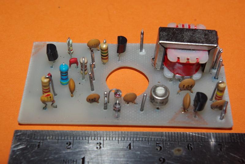
7 Completed main board


8 Component placement Real World Silk screen

9 Track layout (Xray view) Circuit diagram Hope you find this is a useful design and enjoy building it, 73 for now de Nick G0CWA Any comments will be gratefully received and as usual I can be contacted by at n.strong@hotmail.co.uk or via the Radio Board and QRZ forums as G0CWA. I cannot guarantee to see your questions if posted elsewhere REMEMBER TO CHECK THE PCB TRACK LAYOUTS AND MIRROR THEM IF NEEDED. I HAVE PRESENTED THEM AS X-RAY VIEWS OF THE FINAL BOARD!!!!
10 PLEASE NOTE if you downloaded this document from anywhere but or I can not guarantee you will have the latest version, Please inform Dave if it was downloaded from another site. Dave s site is the ONLY ONE I HAVE AUTHORISED to distribute/display my projects and documents. However links to the projects are permitted with Daves permission. I do not supply kits, parts, PCB's or build boards for my projects but am more than willing to help talk you through a build or fault finding via my normal contact methods, or even SKYPE if required for direct contact.


11 Coil labels Tuning Scale
G0CWA ANALOG AF/MF SIGNAL GENERATOR APRIL 2013
 G0CWA ANALOG AF/MF SIGNAL GENERATOR APRIL 2013 INTRODUCTION Hi here is my design for a simple easily customizable signal generator generating variable levels of sin, triangular and square wave signals
G0CWA Mk2 RTL SDR RADIO SEPTEMBER 2012
 G0CWA Mk2 RTL SDR RADIO SEPTEMBER 2012 For use with RTL2832U-based DVB-T USB dongle with the Elonics E4000 tuner Hi, welcome to my latest project my improved version of my SDR radio. This is based on my
Norfolk Amateur Radio Club
 Norfolk Amateur Radio Club The Transmitter & Transmitter Interference Nick M0HGU & Steve G3PND Plan for the Day The Transmitter Introduction, Block diagrams Oscillators, Buffers & Multipliers Modulation
THE INTERMEDIATE VFO
 THE INTERMEDIATE VFO Some Intermediate tutors have reported difficulties in either obtaining parts for the RSGB Intermediate textbook VFO or in getting the VFO going once they have the parts. This alternative
HF Receivers, Part 2
 HF Receivers, Part 2 Superhet building blocks: AM, SSB/CW, FM receivers Adam Farson VA7OJ View an excellent tutorial on receivers NSARC HF Operators HF Receivers 2 1 The RF Amplifier (Preamp)! Typical
The ROSE 80 CW Transceiver (Part 1 of 3)
") Build a 5 watt, 80 meter QRP CW Transceiver!!! Page 1 of 10 The ROSE 80 CW Transceiver (Part 1 of 3) Build a 5 watt, 80 meter QRP CW Transceiver!!! (Designed by N1HFX) A great deal of interest has been
Build a 5 watt, 80 meter QRP CW Transceiver!!! Page 1 of 10 The ROSE 80 CW Transceiver (Part 1 of 3) Build a 5 watt, 80 meter QRP CW Transceiver!!! (Designed by N1HFX) A great deal of interest has been
ZN414Z, ZN415E, ZN416E AM RADIO RECEIVERS
 GEC PLESSEY [SEMICONDUCTORS ZN414Z, ZN415E, ZN416E AM RADIO RECEIVERS FEATURES Single cell operation (1.1 to 1.6 volt, operating range) Low current consumption 150kHz to 3MHz frequency range (i.e. full
The G4EGQ RAE COURSE Lesson 9 Transmitters Lesson 8 looked at a simple transmitter exciter comprising of oscillator, buffer and multiplier stages.
 Lesson 8 looked at a simple transmitter exciter comprising of oscillator, buffer and multiplier stages. The power amplifier The output from the exciter is usually very low and it is necessary to amplify
Homebrew and Experimenters Group HF Inductance Bridge (Compiled by VK2TOX)
") Homebrew and Experimenters Group HF Inductance Bridge (Compiled by VK2TOX) There are a number of ways to measure inductances used in construction of RF equipment. One of the most versatile ways is with
Homebrew and Experimenters Group HF Inductance Bridge (Compiled by VK2TOX) There are a number of ways to measure inductances used in construction of RF equipment. One of the most versatile ways is with
ASSEMBLY MANUAL FOR R3500D DIRECTION FINDING RECEIVER KIT
 SDR-Kits www.sdr-kits.net SDR-Kits is CRKITS Authorised Distributor for Europe ASSEMBLY MANUAL FOR R3500D DIRECTION FINDING RECEIVER KIT Rev. A May 24, 2015 Written by CRKITS http://www.crkits.com Thanks
G6ALU 20W FET PA Construction Information
 G6ALU 20W FET PA Construction Information The requirement This amplifier was designed specifically to complement the Pic-A-Star transceiver developed by Peter Rhodes G3XJP. From the band pass filter an
A GOOD REGENERATIVE RECEIVER WITH SIMPLE FINE TUNING (2008)
") A GOOD REGENERATIVE RECEIVER WITH SIMPLE FINE TUNING (2008) A good SSB-CW-AM regenerative receiver with a fine tuning by moving the wooden stick with a grounded piece of PCB towards the coil. A good regenerative
A GOOD REGENERATIVE RECEIVER WITH SIMPLE FINE TUNING (2008) A good SSB-CW-AM regenerative receiver with a fine tuning by moving the wooden stick with a grounded piece of PCB towards the coil. A good regenerative
RADIO AMATEUR EXAM GENERAL CLASS
 RAE-Lessons by 4S7VJ 1 CHAPTER-7 RADIO AMATEUR EXAM GENERAL CLASS MEASURMENTS By 4S7VJ 7.1 TEST EQUIPMENT & MEASUREMENTS Correct operation of amateur radio equipment involves measurements to ensure optimum
Step by Step Building PJ meter ARDF Receiver Kit. CRKITS.COM August 5, 2013
 Step by Step Building PJ-80 80-meter ARDF Receiver Kit CRKITS.COM August 5, 2013 What is ARDF? ARDF is the abbreviation of Amateur Radio Direction Finding, or so called Fox Hunting. If you are looking
Simple SWL HF- VHF Receiver
 ANTENTOP- 01-2007, # 009 Simple SWL HF- VHF Receiver From the book DX Reception (by Igor Grigorov (RK3ZK), Belgorod, 1994), pp.:76-81. (Article published with inessential cutting) See ANTENTOP- 01-2007,
The Walford Electronics Ford Receiver Kit Project Construction Manual
 The Walford Electronics Ford Receiver Kit Project Construction Manual Walford Electronics Ford Receiver construction manual V1.5 Page 1 of 22 Introduction The Ford receiver has four stages: The first stage
1 TRANSISTOR CIRCUITS
 FM TRANSMITTERS The first group of circuits we will discuss are FM TRANSMITTERS. They can be called SPY TRANSMITTERS, FM BUGS, or a number of other interesting names. They all do the same thing. They transmit
KWM-2/2A Transceiver THE COLLINS KWM-2/2A TRANSCEIVER
 KWM-2/2A Transceiver Click the photo to see a larger photo Click "Back" button on browser to return Courtesy of Norm - WA3KEY THE COLLINS KWM-2/2A TRANSCEIVER Unmatched for versatility, dependability and
RadiØKit Μ CW HAM RADIO TRANSCEIVER KIT. Assembly and operating manual
 RadiØKit-120 20Μ CW HAM RADIO TRANSCEIVER KIT Assembly and operating manual Boreiou Ipirou 78 Kolonos Athens- Greece - 10444 Tel: 210.5150527 210.5132673 www.freebytes.com Thank you for buying RadiØKit-1,
1. What is the unit of electromotive force? (a) volt (b) ampere (c) watt (d) ohm. 2. The resonant frequency of a tuned (LRC) circuit is given by
 volt (b) ampere (c) watt (d) ohm. 2. The resonant frequency of a tuned (LRC) circuit is given by") Department of Examinations, Sri Lanka EXAMINATION FOR THE AMATEUR RADIO OPERATORS CERTIFICATE OF PROFICIENCY ISSUED BY THE DIRECTOR GENERAL OF TELECOMMUNICATIONS, SRI LANKA 2004 (NOVICE CLASS) Basic Electricity,
Department of Examinations, Sri Lanka EXAMINATION FOR THE AMATEUR RADIO OPERATORS CERTIFICATE OF PROFICIENCY ISSUED BY THE DIRECTOR GENERAL OF TELECOMMUNICATIONS, SRI LANKA 2004 (NOVICE CLASS) Basic Electricity,
FM RADIO KIT ESSENTIAL INFORMATION. Version 2.0 GET IN TUNE WITH THIS
 ESSENTIAL INFORMATION BUILD INSTRUCTIONS CHECKING YOUR PCB & FAULT-FINDING MECHANICAL DETAILS HOW THE KIT WORKS GET IN TUNE WITH THIS FM RADIO KIT Version 2.0 Build Instructions Before you start, take
HT-1A Dual Band CW QRP Transceiver. Kit Building Instructions
 HT-A Dual Band CW QRP Transceiver Kit Building Instructions Rev B, July 8, 08 Designed by BD4RG Exclusively distributed by CRKITS.COM and its worldwide distributors Join the group http://groups.io/g/crkits
DEM Part Number L144-28INTCK 144 MHz Transverter Kit and complete kit
 DEM Part Number L144-28INTCK 144 MHz Transverter Kit and complete kit Power Out: Noise Figure and Gain: DC Power Requirement: 50 mw linear minimum 3.5 db NF nominal, 5 dbg maximum 12-15.5 VDC, 13.8 nominal
Quadrature Upconverter for Optical Comms subcarrier generation
 Quadrature Upconverter for Optical Comms subcarrier generation Andy Talbot G4JNT 2011-07-27 Basic Design Overview This source is designed for upconverting a baseband I/Q source such as from SDR transmitter
Application Note Receivers MLX71120/21 With LNA1-SAW-LNA2 configuration
 Designing with MLX71120 and MLX71121 receivers using a SAW filter between LNA1 and LNA2 Scope Many receiver applications, especially those for automotive keyless entry systems require good sensitivity
N3ZI Kits General Coverage Receiver, Assembly & Operations Manual (For Jun 2011 PCB ) Version 3.33, Jan 2012
 Version 3.33, Jan 2012") N3ZI Kits General Coverage Receiver, Assembly & Operations Manual (For Jun 2011 PCB ) Version 3.33, Jan 2012 Thank you for purchasing my general coverage receiver kit. You can use the photo above as a
N3ZI Kits General Coverage Receiver, Assembly & Operations Manual (For Jun 2011 PCB ) Version 3.33, Jan 2012 Thank you for purchasing my general coverage receiver kit. You can use the photo above as a
Electronic Measurements & Instrumentation. 1. Draw the Maxwell s Bridge Circuit and derives the expression for the unknown element at balance?
 UNIT -6 1. Draw the Maxwell s Bridge Circuit and derives the expression for the unknown element at balance? Ans: Maxwell's bridge, shown in Fig. 1.1, measures an unknown inductance in of standard arm offers
Practical Tricks with Transformers. Larry Weinstein K0NA
 Practical Tricks with Transformers Larry Weinstein K0NA Practical Tricks with Transformers Quick review of inductance and magnetics Switching inductive loads How many voltages can we get out of a $10 Home
The Electro-Magnetic Spectrum
 The Electro-Magnetic Spectrum Part Three In This Issue: All about Tubes How a diode rectifier works How a triode amplifier works How the mixer in your receiver works Dear Friends: For quite some time I
4/30/2012. General Class Element 3 Course Presentation. Practical Circuits. Practical Circuits. Subelement G7. 2 Exam Questions, 2 Groups
 General Class Element 3 Course Presentation ti ELEMENT 3 SUB ELEMENTS General Licensing Class Subelement G7 2 Exam Questions, 2 Groups G1 Commission s Rules G2 Operating Procedures G3 Radio Wave Propagation
LM1866 Low Voltage AM FM Receiver
 LM1866 Low Voltage AM FM Receiver General Description The LM1866 has been designed for high quality battery powered medium wave AM and FM receiver applications requiring operation down to 3V The AM section
MFJ-249B HF/VHF SWR ANALYZER
 TABLE OF CONTENTS MFJ-249B... 2 Introduction... 2 Powering The MFJ-249B... 3 Battery Installation... 3 Alkaline Batteries... 3 NiCd Batteries... 4 Power Saving Mode... 4 Operation Of The MFJ-249B...5 SWR
HOMEBREW Q-MULTIPLIER
 HOMEBREW Q-MULTIPLIER This circuit can boost the signal strength in your receiver by 1 or 2 S-units, giving approximately 10 db gain. A Q-multiplier amplifies the Q of the first IF transformer so that
THE AMAZING BARLOW WADLEY XCR-30 CRYSTAL CONTROLLED 30 BAND TRANSISTOR RADIO. (A method to set the AGC) H. Holden, 2018.
 H. Holden, 2018.") THE AMAZING BARLOW WADLEY XCR-30 CRYSTAL CONTROLLED 30 BAND TRANSISTOR RADIO. (A method to set the AGC) H. Holden, 2018. Introduction: The Barlow Wadley XCR-30 radio is well known to amateur radio enthusiasts
THE AMAZING BARLOW WADLEY XCR-30 CRYSTAL CONTROLLED 30 BAND TRANSISTOR RADIO. (A method to set the AGC) H. Holden, 2018. Introduction: The Barlow Wadley XCR-30 radio is well known to amateur radio enthusiasts
Building a Bitx20 Version 3
 Building a Bitx20 Version 3 The board can be broken into sections and then built and tested one section at a time. This will make troubleshooting easier as any problems will be confined to one small section.
HAMTRONICS TB901 FM EXCITER INSTALLATION, OPERATION, & MAINTENANCE
 HAMTRONICS TB901 FM EXCITER INSTALLATION, OPERATION, & MAINTENANCE GENERAL INFORMATION. The TB901 is a single-channel low power fm transmitter (exciter) designed to provide 300-600 milliwatts continuous
WA3RNC 30 METER CRYSTALPLEXER TRANSMITTER KIT ASSEMBLY INSTRUCTIONS
 WA3RNC 30 METER CRYSTALPLEXER TRANSMITTER KIT ASSEMBLY INSTRUCTIONS Description The WA3RNC 30 Meter Crystalplexer is a low power crystal controlled QRP transmitter offering a significantly improved tuning
The Hartley Oscillator
 The Hartley Oscillator One of the main disadvantages of the basic LC Oscillator circuit we looked at in the previous tutorial is that they have no means of controlling the amplitude of the oscillations
HF Amateur SSB Receiver
 HF Amateur SSB Receiver PCB Set for radio club project http://rhelectronics.net PCB for DIY HF Amateur SSB Receiver 20M The receiver is a simple syperheterodyne type with quartz crystal filter. The circuit
Copyright 2012, R. Eckweiler & OCARC, Inc. Page 1 of 5
 Heathkit of the Month #42: by Bob Eckweiler, AF6C Heathkit HD-1422-A Antenna Noise Bridge Introduction: If you work with antennas, an antenna noise bridge can be a very handy tool. Table 1 lists some of
A 100-Watt Transmitter Using a Pair of VT1625s
 12/16/2007 6:00 PM VT1625 100 Watt Transmitter A 100-Watt Transmitter Using a Pair of VT1625s FIG. 10.6 A 100-watt transmitter for five bands, using salvaged TV power transformer and surplus 1625 amplifier
Hendricks QRP Kits BITX20A to BITX17A Conversion Instructions
 Hendricks QRP Kits BITX20A to BITX17A Conversion Instructions 30 November 2008 Converting your BITX20A Kit to a BITX17A Kit is not all that complex. It only requires that you change crystals and some resonance
The 6LE8 One Tube Broadcaster
 The 6LE8 One Tube Broadcaster Introduction The purpose of this broadcaster is to transmit your favorite music to every AM radio in your home. The transmitting power is so low that it should not bother
Receiver Operation at the Component Level
 Receiver Operation at the Component Level Unit 9. Activity 9.4. How a Receiver Works Purpose: The objective of this lesson is to allow the student to explore how a receiver works at the component level.
Technical Info Doc: Galileo2 A simple Direct Conversion Receiver for 20.1MHZ
 Fox Delta Amateur Radio Projects & Kits FD Galileo2 Technical Info Doc: Galileo2 A simple Direct Conversion Receiver for 20.1MHZ This Project is dedicated to our beloved scientist Galileo: Galileo was
Handy dandy little circuit #17 #17
 Handy dandy little circuit #17 #17 Download # 17 in PDF There are a lot of alarm systems on the market but you might be inclined to build your own. This little project can be put together using inexpensive
2-Tone Generator For 145Mhz
 Wolfgang Schneider, DJ8ES 2-Tone Generator For 145Mhz An RF amplifier stage is not only classified by amplification, which is as high as possible, and thus by its maximum output. What is frequently not
The KW 76A MOBILE RECEIVER
 The KW 76A MOBILE RECEIVER The KW 76A Receiver is designed primarily for mobile operation. The compact layout makes it particularly suitable for under dash mounting in a vehicle. When used at a Home station
PRACTICE. Amateur Radio Operator Certificate Examination. Advanced Qualification
 Amateur Radio Operator ertificate Examination Advanced Qualification 2019-04-03 To pass this exam, you must correctly answer 35 out of 50 questions Exam Number: 115916 1. (A-007-008-002) Why would one
About LC Meter This is one of the most accurate and simplest LC inductance / capacitance Meters that one can find, yet one that you can easily build y
 Home Electronic Store Electronic Blog Electronic Schematics Tutorials Downloads Lin Very Accurate LC Meter based on PIC16F84A IC. LC Meter Part's List: 2x 1K 2x 6.8K 1x 47K 3x 100K 1x 10K POT 2x 10pF 1x
KN-Q10 Assembly Manual
 KN-Q10 Assembly Manual Translated by Adam Rong, BD6CR/4 with permission from Ke Shi, BA6BF Edited by Stephen, VK2RH Revision B, Oct 14, 2010 Thank you for purchasing the KN-Q10 4 Band SSB/CW Dual Mode
Antenna Design for FM-02
 Antenna Design for FM-02 I recently received my FM-02 FM transmitter which I purchased from WLC. I researched the forum on what antennas where being used by the DIY community and found a nice write-up
Some hints/tips on how to assemble nice COAX TRAPS!
 Some hints/tips on how to assemble nice COAX TRAPS! Before we start to assemble our traps, here some general info as introduction : Coax traps are cheap, easy to assemble in a reproducible manner, very
AN IMPROVED SHORTWAVE REGENERATIVE RECEIVER
 AN IMPROVED SHORTWAVE REGENERATIVE RECEIVER Ramón Vargas Patrón rvargas@inictel-uni.edu.pe INICTEL-UNI Sensitivity and selectivity are issues that will invariably concern a short wave listener when he
Wimborne Publishing, reproduce for personal use only
 In part 1 we looked at some of the principles involved with measuring magnetic fields. This time, we take a more practical approach and look at some experimental circuits. The circuits illustrated are
Topic Advanced Radio Receivers. Explain that an RF amplifier can be used to improve sensitivity;
 Learning Objectives: At the end of this topic you will be able to; Explain that an RF amplifier can be used to improve sensitivity; Explain that a superheterodyne receiver offers improved selectivity and
LM1868 AM FM Radio System
 LM1868 AM FM Radio System General Description The combination of the LM1868 and an FM tuner will provide all the necessary functions for a 0 5 watt AM FM radio Included in the LM 1868 are the audio power
Treetop Circuits Owner s Manual for SB-SB-600 Adapter Version 1
 The SB-600 SSB adapter from Treetop Circuits (Fig. 1) is designed specifically as an accessory to the Hammarlund SP-600 series of receivers. It provides enhanced performance on SSB and CW signals, using
MFJ-203 Bandswitched Dip Meter
 MFJ-203 Bandswitched Dip Meter Thank you for purchasing the MFJ-203 Bandswitched Dip Meter. The MFJ-203 Bandswitched Dip Meter is a solid state bandswitched adaptation of the traditional grid dip meter.
Low voltage high performance mixer FM IF system
 DESCRIPTION The is a low voltage high performance monolithic FM IF system incorporating a mixer/oscillator, two limiting intermediate frequency amplifiers, quadrature detector, logarithmic received signal
Frequency range: BAND RANGE MHz MHz
 INSTRUCTION SHEET NO. 20 POWER-MITE PM3 and PM3A DESCRIPTION The Power-Mite 3 and 3A are self-contained CW transceivers covering 40 and 20 meters. The receiver is compromised of a variable oscillator operating
: Hacking Bitx Version3B, C: : 20mt to 40mt band: PART I
 : Hacking Bitx Version3B, C: : 20mt to 40mt band: PART I Fig 1: Bitx Ver3C SBL-1 20 Conversion for Bitx40 The picture in Fig1 is a Bitx3C SBL-1 for 40mt band, constructed from the Bitx Version 3C SBL-1
ATUs - ANTENNA TUNING UNITS THE ATU. An Antenna Tuning Unit MAKE YOUR OWN ATU
 ATUs - ANTENNA TUNING UNITS THE ATU An Antenna Tuning Unit MAKE YOUR OWN ATU The circuit diagram below shows the circuit for a typical Pi type ATU which seems to be a popular arrange ment for many ATUs.
Pacific Antenna 20 and 40M Lightweight Dipole Kit
 Pacific Antenna 20 and 40M Lightweight Dipole Kit Antenna diagram showing configuration and lengths when assembled 7 8 16 9 16 9 Description The Pacific Antenna lightweight dual band dipole kit provides
ericssonz LBI-38640E MAINTENANCE MANUAL FOR VHF TRANSMITTER SYNTHESIZER MODULE 19D902780G1 DESCRIPTION
 MAINTENANCE MANUAL FOR VHF TRANSMITTER SYNTHESIZER MODULE 19D902780G1 TABLE OF CONTENTS Page DESCRIPTION........................................... Front Cover GENERAL SPECIFICATIONS...................................
You Just Brought an Old Radio Home: Now What Do You Do?
 You Just Brought an Old Radio Home: Now What Do You Do? Raymond Cady goldenageradiorestoration.com Whether you are just beginning to collect antique radios or you have been at it for a number of years,
ssb transceiver single-band using the LM373 communications IC
 single-band ssb transceiver using the LM373 communications IC How to use the versatile LM373 and several other ICs to build a compact ssb transceiver for 14 MHz About two years ago a new products announcement
Knight Kit V44 VFO Stabilized by the Cumbria Design X-Lock 3.0
 Knight Kit V44 VFO Stabilized by the Cumbria Design X-Lock 3.0 The Knight V44 VFO has a place in history. It was designed in the late 1950 s as a self contained VFO intended to plug into the crystal socket
Amateur Radio Examination EXAMINATION PAPER No. 276 MARKER S COPY
 01-3-(a) The Amateur Service in New Zealand is administered through this prime document: a the New Zealand Radiocommunications Regulations b the Broadcasting Act c the Telecommunications Act d the Radio
Take another look at the Noise Bridge:
 Take another look at the Noise Bridge: Author K.P.Barnsdale ZL3KB Date 21 October 1998 Diagrams: 1. Circuit diagram. 2. PCB layout 3. Front panel layout 4. Internal layout diagram 5. Inductance chart Introduction
S-RockMite QRP Kit User Manual. Welcome to visit the home page to obtain the latest data. 1 / 23. Revision V161101
 S-RockMite QRP Kit User Manual Revision V161101 Welcome to visit the home page www.lxqqfy.com to obtain the latest data. 1 / 23 1. Introduction This is a very small volume of simple 40 meter band micro-power
EE12: Laboratory Project (Part-2) AM Transmitter
 AM Transmitter") EE12: Laboratory Project (Part-2) AM Transmitter ECE Department, Tufts University Spring 2008 1 Objective This laboratory exercise is the second part of the EE12 project of building an AM transmitter in
EE12: Laboratory Project (Part-2) AM Transmitter ECE Department, Tufts University Spring 2008 1 Objective This laboratory exercise is the second part of the EE12 project of building an AM transmitter in
Construction Guide of TH300S
 Construction Guide of TH300S TH300S is a 2-band SSB/CW transceiver, used with DDS as LO, and features dual operation system ham band and general coverage band. A doubly balanced diode ring mixer is used
- have been successfully combined in the RCA -developed insulated -gate metal -oxide -
 A PUBLICATION OF RCA ELECTRONIC COMPONENTS AND DEVICES VOL. 27, NO. 3 1967, RADIO CORPORATION OF AMERICA OCTOBER, 1967 Using the MOS Field -Effect Transistor As a Product Detector and AGC Gate By W. M.
Technical Bulletin A Versatile Pulse Tester Page 1 of 6
 Technical Bulletin A Versatile Pulse Tester Page 1 of 6 A Versatile Pulse Tester By G8MNY (BATC's CQTV No 195, Updated Oct 07) (8 Bit ASCII Graphics use code page 437 or 850) This tester based on ideas
33609/J Limiter/Compressor
 33609/J Limiter/Compressor Technical Handbook 527-149 Issue 3 2002 AMS Neve plc own the copyright of all information and drawings contained in this manual which are not to be copied or reproduced by any
For the filter shown (suitable for bandpass audio use) with bandwidth B and center frequency f, and gain A:
 with bandwidth B and center frequency f, and gain A:") Basic Op Amps The operational amplifier (Op Amp) is useful for a wide variety of applications. In the previous part of this article basic theory and a few elementary circuits were discussed. In order to
Basic Op Amps The operational amplifier (Op Amp) is useful for a wide variety of applications. In the previous part of this article basic theory and a few elementary circuits were discussed. In order to
S-Pixie QRP Kit. Student Manual. Revision V 1-0
 S-Pixie QRP Kit Student Manual Revision V 1-0 Introduction The Pixie 2 is a small, versatile radio transceiver that is very popular with QRP (low power) amateur radio operators the world over. It reflects
AA-35 ZOOM. RigExpert. User s manual. Antenna and cable analyzer
 AA-35 ZOOM Antenna and cable analyzer RigExpert User s manual . Table of contents Introduction Operating the AA-35 ZOOM First time use Main menu Multifunctional keys Connecting to your antenna SWR chart
ALX-SSB 5 Band Filter Assembly Manual 19 November 2018
 ALX-SSB 5 Band Filter Assembly Manual 19 November 2018 Contents Theory of Operation:... 1 Figure 1... 2 Parts Included:... 4 Board Overview:... 5 Figure 2... 5 Figure 3... 5 Board Assembly:... 6 Cable
VCO Design Project ECE218B Winter 2011
 VCO Design Project ECE218B Winter 2011 Report due 2/18/2011 VCO DESIGN GOALS. Design, build, and test a voltage-controlled oscillator (VCO). 1. Design VCO for highest center frequency (< 400 MHz). 2. At
Radio Receivers. Al Penney VO1NO
 Radio Receivers Al Penney VO1NO Role of the Receiver The Antenna must capture the radio wave. The desired frequency must be selected from all the EM waves captured by the antenna. The selected signal is
Construction Manual 4m-Linear-Transverter XV4-15
 Construction Manual 4m-Linear-Transverter XV4-15 Holger Eckardt DF2FQ Kirchstockacherstr. 33 D-85662 Hohenbrunn 3207 Technical data exciter frequency: 21.0... 21.5 MHz RF frequency: 70.0.. 70.5 MHz supply
onlinecomponents.com FET Circuit Applications FET Circuit Applications AN-32 National Semiconductor Application Note 32 February 1970
 FET Circuit Applications National Semiconductor Application Note 32 February 1970 Polycarbonate dielectric Sample and Hold With Offset Adjustment TL H 6791 1 Long Time Comparator TL H 6791 2 The 2N4393
EE301 ELECTRONIC CIRCUITS CHAPTER 2 : OSCILLATORS. Lecturer : Engr. Muhammad Muizz Bin Mohd Nawawi
 EE301 ELECTRONIC CIRCUITS CHAPTER 2 : OSCILLATORS Lecturer : Engr. Muhammad Muizz Bin Mohd Nawawi 2.1 INTRODUCTION An electronic circuit which is designed to generate a periodic waveform continuously at
Low-voltage mixer FM IF system
 DESCRIPTION The is a low-voltage monolithic FM IF system incorporating a mixer/oscillator, two limiting intermediate frequency amplifiers, quadrature detector, logarithmic received signal strength indicator
50 (FET) Field Effect Transistor Projects F. G. RAYER, T. ENG. (CEI), ASSOC. IERE
 Field Effect Transistor Projects F. G. RAYER, T. ENG. (CEI), ASSOC. IERE") 50 (FET) Field Effect Transistor Projects F. G. RAYER, T. ENG. (CEI), ASSOC. IERE 50 (F.E.T.) Field Effect Transistor Projects by F. G. RAYER, T. Eng. (CEI), Assoc. IERE BABANI PRESS The Publishing Division
50 (FET) Field Effect Transistor Projects F. G. RAYER, T. ENG. (CEI), ASSOC. IERE 50 (F.E.T.) Field Effect Transistor Projects by F. G. RAYER, T. Eng. (CEI), Assoc. IERE BABANI PRESS The Publishing Division
A 75-Watt Transmitter for 3 Bands Simplified Shielding and Filtering for TVI BY DONALD H. MIX, W1TS ARRL Handbook 1953 and QST, October 1951
 A 75-Watt Transmitter for 3 Bands Simplified Shielding and Filtering for TVI BY DONALD H. MIX, W1TS ARRL Handbook 1953 and QST, October 1951 The transmitter shown in the photographs is a 3-stage 75-watt
BITX40 with Raduino - tips and mods
 BITX40 with Raduino - tips and mods Also check out hfsigs blogspot http://bitxhacks.blogspot.co.uk/ Clicks during tuning I assume you are talking about the Raduino clicking as you tune. I'm not having
2m Weak Signal Sources January 2018
 2m Weak Signal Sources January 2018 Rick Campbell This white paper describes a set of signal sources at power levels from -30dBm to +12dBm in the 144 MHz amateur radio band. All are legal for direct connection
FC3 Project Info: PIC18F /500MHZ Frequency Counter & RF Meter. This project is developed for Amateur Radio Community by:
 Fox Delta Amateur Radio Projects & Kits FC3-0915 FC3 Project Info: PIC18F4550 50/500MHZ Frequency Counter & RF Meter This project is developed for Amateur Radio Community by: Antonio Alfinito / I2TZK Dinesh
LPF-9B Nine band low pass filter module kit ( meters)
") LPF-9B Nine band low pass filter module kit (80-60-40-30-20-17-15-12-10 meters) Assembly manual Last update: March 1, 2018 ea3gcy@gmail.com Most recent updates and news at: www.ea3gcy.com Thanks for constructing
LPF-9B Nine band low pass filter module kit (80-60-40-30-20-17-15-12-10 meters) Assembly manual Last update: March 1, 2018 ea3gcy@gmail.com Most recent updates and news at: www.ea3gcy.com Thanks for constructing
Operation Manual. Model SG Elenco Precision Wide Band Signal Generator
 99 Washington Street Melrose, MA 02176 Phone 781-665-1400 Toll Free 1-800-517-8431 Visit us at www.testequipmentdepot.com Elenco Precision Wide Band Signal Generator Model SG-9000 Operation Manual CONTENTS
Type Ordering Code Package TDA Q67000-A5168 P-DIP-18-5
 Video Modulator for FM-Audio TDA 5666-5 Preliminary Data Bipolar IC Features FM-audio modulator Sync level clamping of video input signal Controlling of peak white value Continuous adjustment of modulation
The Amazing MFJ 269 Author Jack Tiley AD7FO
 The Amazing MFJ 269 Author Jack Tiley AD7FO ARRL Certified Emcomm and license class Instructor, Volunteer Examiner, EWA Technical Coordinator and President of the Inland Empire VHF Club What Can be Measured?
A SDR-based receiver for Es hail-2 and the BACAR 6, 10 GHz beacons 30 July 2018
 A SDR-based receiver for Es hail-2 and the BACAR 6, 10 GHz beacons 30 July 2018 Hannes Coetzee, ZS6BZP Introduction If all goes according to plan the Qatar Satellite Company (Es hailsat) will place its
Cricket 80a Assembly Manual v Copyright David Cripe NM0S The 4 State QRP Group
 Cricket 80a Assembly Manual v. 1.0 Copyright 2017 David Cripe NM0S The 4 State QRP Group Introduction Thank you for purchasing a CRICKET 80a Transceiver. We hope you will enjoy building it and find it
Hear SSB amateurs on your shortwave receiver
 Hear SSB amateurs on your shortwave receiver Peter Parker VK3YE Since most amateurs switched from AM to single sideband more than 40 years ago, it hasn't been possible to receive them with an unaided shortwave
Power Pulse Modulator A High Performance Versatile Square Pulse Generator
 Power Pulse Modulator A High Performance Versatile Square Pulse Generator Model: PWM-OCXi v2.2 Type: High Voltage, 9A, 340V, 1.5MHz, Active Protection Features and Specifications * Max current varies with
SWR myths and mysteries.
 SWR myths and mysteries. By Andrew Barron ZL3DW September 2012 This article will explain some of the often misunderstood facts about antenna SWR at HF and uncover some popular misconceptions. The questions