FX Type: Distortion 1.95 W x H Terms of Use: Slow Loris Slow Loris
|
|
|
- Adam Barber
- 5 years ago
- Views:
Transcription

1 Slow Loris 2015 edition madbeanpedals FX Type: Distortion Based on the ProCo Rat Changes for the 2015 edition: Slight layout adjustments. No circuit changes. Previous version: W x H Terms of Use: You are free to use purchased Slow Loris circuit boards for both DIY and small commercial operations. You may not offer Slow Loris boards for resale or as part of a kit in a commercial fashion. Peer to peer re-sale is, of course, okay
2 B.O.M. Resistors Caps Diodes R1 1M C1 22n D1, D2 Red LED R2 1k C2 1n D3 1N5817 R3 1M C3 30pF D4, D5 1N914 R4 47R C4 100pF Transistors R5 560R C5 4u7 Q1 2N5457 R6 1k C6 2u2 IC R7 1k5 C7 1uf IC1 LM308 R8 1M C8 3n3 Switch R9 10k C9 1uf CLIP SPDT R10 10k C10 100uF Pots R11 4k7 C11 47uF SWEEP 1kB R12 47R C12 22n VOL 100kA R13 100k C13 100n CUT 100kA R14 100k C14 10n GAIN 100kA Shopping List Value QTY Type Rating 47R 2 Carbon / Metal Film 1/4W 560R 1 Carbon / Metal Film 1/4W 1k 2 Carbon / Metal Film 1/4W 1k5 1 Carbon / Metal Film 1/4W 4k7 1 Carbon / Metal Film 1/4W 10k 2 Carbon / Metal Film 1/4W 100k 2 Carbon / Metal Film 1/4W 1M 3 Carbon / Metal Film 1/4W 30pF 1 Ceramic 16v min. 100pF 1 Ceramic 16v min. 1n 1 Film 16v min. 3n3 1 Film 16v min. 22n 2 Film 16v min. 10n 1 Film 16v min. 100n 1 Film 16v min. 1uf 2 Film 16v min. 2u2 1 Electroltyic 16v min. 4u7 1 Electroltyic 16v min. 47uF 1 Electroltyic 16v min. 100uF 1 Electroltyic 16v min. Red LED 2 3 or 5mm, Diffused 1N N N LM308 1 SPDT 1 On/On 1kB 1 PCB Right Angle 16mm 100kA 3 PCB Right Angle 16mm If you cannot find a 30pF cap, use 33pF for C3. 2
3 3


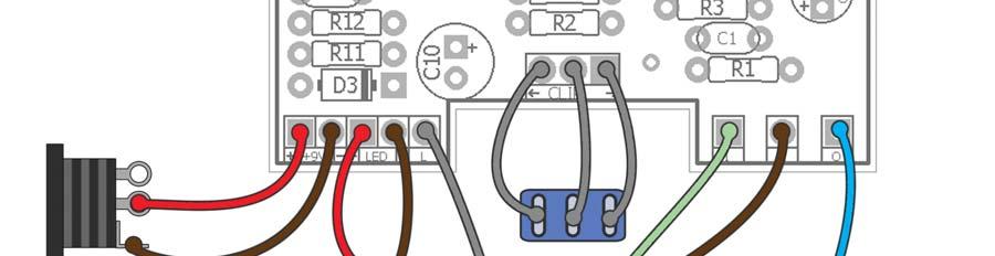

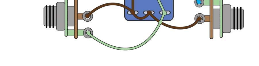
4 Wiring Diagram 4
5 1590B Drill Template 4.44 W x 6.45 H Photoshop Drill Template: 5
.")
6 Overview: Much like the venerated Ibanez Tube Screamer the Rat needs little introduction. It is part of the holy trinity of dirt pedals that nearly every rock guitar player has owned or played through at some point (the other being the Big Muff ). But, unlike the smooth and refined sound of the Tube Screamer, the Rat is more like a distant uncle you know, the one that always smells like stale cigars and bottom-of-the-well whiskey; rude, abrasive and sometimes just plain ol mean. While the Rat lacks smoothness (and pushes the boundaries on acceptable signal to noise ratio) it makes up for it with lots of character. It is a textured distortion; like putting a fine layer of gritty sand over your guitar tone. One can almost imagine ripping fat riffs while playing Round and Round at your local bar gig, flipping your long mane of hair while the ladies swoon over your tiger striped spandex. Well, maybe that s just me. Anyway, the Slow Loris is a clone of the Rat with a couple extra mods. The first is an additional knob labeled Sweep. This is a 1k pot in series with R4 (also known as the Ruetz mod ). The Sweep pot lets you change the clipping frequency of the gain stage. It is most useful at lower gain settings and will darken up the tone a bit as you turn it up. Fully counter-clockwise is the stock Rat sound. The second mod is a switch that lets you select between the stock 1n914 clipping diodes and LED clipping. LEDs are louder and crunchy. The 2014 version of the Slow Loris added C14, which will help smooth out some of the high frequencies in LED clipping mode. C14 is optional. 6
7 Circuit Analysis: R1 is a pulldown resistor. It helps reduce popping when the effect is switched on. C1 is a coupling cap. It lets the AC guitar signal through while preventing the DC voltage the circuit uses from escaping back into the guitar. R3 is a biasing resistor for IC1. It connects to the biasing voltage supply (Vb) to provide the proper current to the op-amp for operation. It also sets the input impedance of the op-amp (R2 adds a very small amount to the total input impedance but can be ignored). R2 is a small signal limiting resistor at the non-inverted input of the op-amp. It also forms an LP filter with C2 centered at 159KHz to reduce RF interference. C3 is the slew rate compensation capacitor. Slew is actually a bit more complicated to explain but the basic idea is it measures how quickly the op-amp reacts to voltage and/or frequency changes at its input. In many other op-amps, this is pre-determined, but in the LM308 it can be adjusted, or compensated, by an external capacitor. Here s a good read on the slew rate of the Rat. C4 is a filtering cap used in the feedback loop of IC1. At high gain settings, it helps reduce high frequency noise. The Gain pot sets the overall distortion level from lowest to highest as it goes clockwise. It works in parallel with C4, so at low gain settings there is little filtering effect. At high gain settings, the resistance value of the Gain pot is high which creates an audible filter. R4 and R5 set the maximum amount of gain. The lower the values, the higher the gain. These resistors are in parallel, so their total value is equivalent to about 43R. However, they form different frequency cutoff ranges with the two caps. One is 1540Hz and the other is 60Hz. What this means is that frequencies below those ranges are clipped less, and vice versa. This filter combo probably has a lot to do with the graininess of the Rat. The Sweep pot has already been explained, but note that at higher settings of the Sweep pot, the maximum gain of IC1 is reduced. This is because R4 and the 1k pot are additive, and we already know that high resistor values on either R4 or R5 will reduce the maximum gain of IC1. Additionally, that 1540Hz filter set by the 47R/2u2 combo becomes 69Hz at 1.047k/2u2. This is why the tone gets darker as the Sweep pot goes up. R6 is another signal limiting resistor. This is a common technique used on the outputs of opamps to reduce noise. C7 is a coupling cap. It blocks the DC coming from IC1 while permitting the AC signal to pass onto the amp or next effect. The large value (1uF) means that all guitar frequencies will pass. D1, D2, D4 and D5 are the clipping diodes. These diodes clip the AC signal corresponding to their forward voltage drop. High forward voltages means the signal is clipped less and vice versa. This is why the LEDs are louder they have a higher forward voltage than the 1n914. Since our DC is sitting at 0v, these diodes are connected to ground (without C7, they would have to be connected to the Vb supply to perform the clipping operation). C10 is an additional smoothing cap used only with the LED clippers. The tone section of the Slow Loris is comprised of the Cut knob, R7 and C8. This forms a passive LP filter which is variable from bright to dark. At full counter-clockwise, the series resistance of the Cut knob is 0, and the filter reduces to R7/C8 which centers around 32KHz: well above human hearing range. When the Cut knob is turned up, the series resistance increases so that we are left with 101.5k/3n3 when it is full clockwise. This filter then centers around 475Hz. This gives the tone knob a very large range of frequency cutting. You could shift it further down the frequency spectrum simply by increasing the value of 3n3. This would be useful when using the Slow Loris for bass guitar. C12 is a coupling cap between the tone and output buffer section. It also forms a very low HP filter with the R8 resistor. 7
8 R8, Q1 and R9 form the output buffer, which is used to compensate for signal loss due to the passive tone filter in the previous section. R8 sets the input impedance of Q1 and serves to bias the gate of the 2n5457. Side note: in previous versions of the Slow Loris, this was connected to the Vb supply. Either way works the same, but most schematics of the Rat have this resistor connected to ground, so the change was made to keep it true to the original. R9 sets the output impedance of the buffer. The value here is not too critical. It needs to be large enough so that the source of Q1 is not connected to ground, but not too large. I m sure there is a better explanation of that. C9 is out final coupling cap. It restores our AC signal to deliver it to the amp, or next effect. The value here is large so that all frequencies pass. R10 was included because I saw it on at least one Rat schematic. I don t know how prevalent this resistor was over the history of the pedal, and I ve never used it. But, it was included nonetheless to be as accurate as possible. I suggest leaving it off. Its function seems to be to set the output impedance of the circuit, but is superfluous since our Volume pot already does this. In fact, it will reduce the total volume output of the circuit since it is in parallel with the volume pot: another reason to leave it off. Our Volume pot sets the total output of the circuit via a voltage divider. At full counter clockwise, it pulls the output to ground, i.e. no output. At full clockwise it delivers the full output. R11 is the current limiting resistor for the LED indicator used on the bypass switch. 4k7 is standard, but other values will work. Higher values result in a less bright LED. D3 is used for reverse polarity protection. This prevents inebriated rockers from connecting a positive tip DC supply to our Slow Loris and destroying it. The 1n5817 is used here due to its low voltage drop. R12 is a series resistor used to reduce noise on our power supply. It forms a filter network with C10 and C13. C10 and C13 are used for smoothing out our power supply signal. The 100uF stores plenty of charge to deliver to our effect consistently. The 100n is used in parallel to reduce any DC ripple coming from our power supply. Finally, R13, and R14 form a voltage divider to create our bias supply voltage. Since they are equal value the incoming 9v voltage is reduced by half to 4.5v. The high values used here (100k) also reduce the total current available for the biasing resistors used in our circuit. C11 completes the circuit and keeps charged up to keep the Vb supply constant. 8
Dirtbaby FX TYPE: Delay Based on the EHX DMM 2016 madbeanpedals
 Dirtbaby FX TYPE: Delay Based on the EHX DMM 2016 madbeanpedals 3.325 W x 2.325 H Terms of Use: You are free to use purchased circuit boards for both DIY and small commercial operations. You may not offer
2.15 W x 1.95 H. Changes to the 2015 edition
 NOM NOM FX Type: Filter 2015 edition Based on the MXR Phase 90 2015 madbeanpedals Download the previous version documentation here: http://www.madbeanpedals.com/projects/nomnom/nomnom.zip 2.15 W x 1.95
Stage Fright 2015 edition FX TYPE: Phaser Based on the Maestro Phaser 2015 madbeanpedals
 Stage Fright 2015 edition FX TYPE: Phaser Based on the Maestro Phaser 2015 madbeanpedals 2.3" W x 3.45" H Previous Version: http://www.madbeanpedals.com/stagefright/stagefright.zip Terms of Use: You are
Cave Dweller 2015 edition FX Type: Delay 2015 madbeanpedals
 Cave Dweller 2015 edition FX Type: Delay 2015 madbeanpedals 1.3" W x 1.975" H (main board) Previous Version: http://www.madbeanpedals.com/projects/cavedweller/cavedweller_drill.zip Terms of Use: You are
Aquaboy FX TYPE: Delay Based on the Boss DM madbeanpedals
 Aquaboy FX TYPE: Delay Based on the Boss DM-2 2016 madbeanpedals 2.3 W x 3.125 H 1.29.17 Correction see page 6. Note: the M pad by the Delay pot is for modulation control (see the AB_MOD documentation
Weener Wah FX TYPE: Wah Wah Based on the Clyde McCoy 2016 edition madbeanpedals
 Weener Wah FX TYPE: Wah Wah Based on the Clyde McCoy 2016 edition madbeanpedals 1.95 W x 2.275 H Terms of Use: You are free to use purchased WeenerWah circuit boards for both DIY and small commercial operations.
Blues King. FX TYPE: Overdrive Images VFE and MBP Project Doc madbeanpedals W x H
 Blues King FX TYPE: Overdrive Images VFE and MBP Project Doc madbeanpedals 2.17 W x 2.025 H Note: Use the values listed on the image above not the values indicated on the silk-screen of the PCB. Some values
Triumvirate. FX TYPE: Multi-Band Distortion Images VFE and MBP Project Doc madbeanpedals W x 2.01 H
 Triumvirate FX TYPE: Multi-Band Distortion Images VFE and MBP Project Doc madbeanpedals 2.17 W x 2.01 H Note: Use the values listed on the image above not the values indicated on the silk-screen of the
FREEKOUT FX TYPE: Ring Modulator Based on the EHX Frequency Analyzer 2015 madbeanpedals
 FREEKOUT FX TYPE: Ring Modulator Based on the EHX Frequency Analyzer 2015 madbeanpedals 2.3 W x 3.025 H This project requires an 18v 100mA (or more) center tip negative power supply. I recommend the Dunlop
Total Recall FX Type: Delay Based on the EHX Deluxe Memory Man 2015 madbeanpedals
 Total Recall FX Type: Delay Based on the EHX Deluxe Memory Man 2015 madbeanpedals 3.34" W x 3.875" H Terms of Use: You are free to use purchased Total Recall circuit boards for both DIY and small commercial
VFE Choral Reef. FX TYPE: Chorus Images VFE and MBP Project Doc madbeanpedals Aug. 2 nd update see pg W x 2.05 H
 VFE Choral Reef FX TYPE: Chorus Images VFE and MBP Project Doc madbeanpedals Aug. 2 nd update see pg.4 2.17 W x 2.05 H Terms of Use: These projects are intended for DIY use only and may not be used in
Dig Dug madbeanpedals FX Type: Sequencer W x 3.25 H
 Dig Dug2 2015 madbeanpedals FX Type: Sequencer 4.15 W x 3.25 H B.O.M. Resistors Caps Diodes R1 1M C1 100n D1 1N5817 R2 1M C2 220n D2 - D4 1n914 R3 10k C3 15n LED1-8 3mm Red R4 330k C4 2n2 PATT 3mm Red
Blueprint. FX TYPE: Delay Images VFE and MBP Project Doc madbeanpedals W x H
 Blueprint FX TYPE: Delay Images VFE and MBP Project Doc madbeanpedals 2.17 W x 2.025 H Note: Use the values listed on the image above not the values indicated on the silk-screen of the PCB. Some values
Tractor BEam. FX TYPE: Phaser Images VFE and MBP Project Doc madbeanpedals
 Tractor BEam FX TYPE: Phaser Images VFE and MBP Project Doc madbeanpedals 2.17 W x 2.02 H Note: This project is built on the Enterprise PCB. It s the same circuit as the Tractor Beam with a few value modifications.
BMC018. Analog Drum. Last updated
 BMC018. Analog Drum. Last updated 11-26-2013 I Features II Schematics A.Master Schematic. B.Input/Decay C.VCO D.VCA E.Power Connections. III Construction A.Parts List B.The Board I. Features This module
Super Nova Distortion
 Super Nova Distortion The Super Nova is a reworking of the Marshall Guv'nor circuit. It uses the same gain structure as its parent design but is EQ'ed quite differently. The basic tone from the gain stages
Mobius Strip. FX TYPE: Dual Delay Images VFE and MBP Project Doc madbeanpedals W x H
 Mobius Strip FX TYPE: Dual Delay Images VFE and MBP Project Doc madbeanpedals 2.17 W x 2.025 H Note: Use the values listed on the image above not the values indicated on the silk-screen of the PCB. Some
VFE Merman. FX TYPE: Overdrive Images VFE and MBP Project Doc madbeanpedals W x H
 VFE Merman FX TYPE: Overdrive Images VFE and MBP Project Doc madbeanpedals 2.17 W x 2.025 H Note: Use the values listed on the image above not the values indicated on the silk-screen of the PCB. Some values
INTO THE UNKNOWN Build Document last updated may 2016 Version
 INTO THE UNKNOWN Build Document last updated may 2016 Version 1.0 2015 'Into the Unknown Guitar Synthesizer Deluxe' is a CMOS based fuzz centered around the CD4046 PLL (phase locked loop) chip and a CD4015
Build Guide CascadiA. GeFet Preamp
 Build Guide CascadiA GeFet Preamp Disclaimery stuff: This project is meant to be assembled by fellow DIYers from the Madbean forum and should only be used for the forces of good. Any other uses prohibited
Rangemaster Treble Booster Kit Building Manual
 Rangemaster Treble Booster Kit Building Manual Effect Pedal Kits: Rangemaster Treble Booster The Dallas Rangemaster is the most famous treble booster effect pedal, and it was the first pedal of its kind.
SC Series. SC Series High Voltage Power Supply
 High Voltage Power Supply General Description The high voltage power supplies are the workhorse of the high voltage industry. They provide isolated outputs of up 9kV and 10 Watts in power (depending on
Axis Fuzz Kit Building Manual
 Axis Fuzz Kit Building Manual Effect Pedal Kits: Axis Fuzz The Axis Fuzz Kit is based in the Roger Mayer Axis Fuzz, the effect pedal responsible for Jimi Hendrix sound in Axis Bold As Love. What else is
THE GREEN CURRANT TREMOLO Build Document last updated june 2017 for PCB version 1.5
 THE GREEN CURRANT TREMOLO Build Document last updated june 2017 for PCB version 1.5 The Green Currant tremolo is a very percussive and vibey tremolo based around the TDA7052A amplifier chip. It splits
TWIN PEAKS TREMOLO. Build Guide for v3.1
 TWIN PEAKS TREMOLO Build Guide for v3.1 Revision 3.1 David Rolo 2017 Reference Quantity Value Description Switches Multiplier 1 1 pole 6 pos. rotary switch Shape 1 1 pole 8 pos. rotary switch Trem Type
Tone Stack and Frequency Response. for Regal/Lifco Model 630 and Amplifiers
 Tone Stack and Frequency Response for Regal/Lifco Model 630 and 630 2 Amplifiers (rev last updated April 28, 206) The noted amplifiers are fitted with two knobs for tone control labelled Treble and Bass.
The Triplet. FX TYPE: Comp+Oct+Dist Images VFE and MBP Project Doc madbeanpedals W x H
 The Triplet FX TYPE: Comp+Oct+Dist Images VFE and MBP Project Doc madbeanpedals 2.17 W x 2.025 H Note: Use the values listed on the image above not the values indicated on the silk-screen of the PCB. Some
Chapter 9: Operational Amplifiers
 Chapter 9: Operational Amplifiers The Operational Amplifier (or op-amp) is the ideal, simple amplifier. It is an integrated circuit (IC). An IC contains many discrete components (resistors, capacitors,
Ibanez Tube Screamer 808
 History Ibanez Tube Screamer 808 The Ibanez Tube Screamer is an overdrive pedal. The most popular use of a tube screamer is to push a tube amp to make it overdrive more. The pedal has a characteristic
2015 ed. FX Type: Univibe 2015 madbeanpedals W x 3.29 H
 Harbinger One 2015 ed. FX Type: Univibe 2015 madbeanpedals 3.25 W x 3.29 H Harbinger One PCBs purchased form madbeanpedals may be used for small amounts of commercial building without prior consent. Keep
Electric Druid 4 second Digital Delay Project
 Electric Druid 4 second Digital Delay Project Overview! 2 Build Instructions! 2 Populate the PCB! 2 Resistors! 2 Cup of tea and soldering check! 3 Power protection diode! 4 Ground link wire! 4 IC sockets!
presents FX TYPE: VIBRATO m2011 madbeanpedals Release date: revised see highlighted notes Thanks, Paul!
 http://www.madbeanpedals.com presents Quadrovibe FX TYPE: VIBRATO m2011 madbeanpedals Release date: 07.1.11 revised 10.26 see highlighted notes Thanks, Paul! The Quadrovibe is a unique Vibrato/Tremolo
LM2900 LM3900 LM3301 Quad Amplifiers
 LM2900 LM3900 LM3301 Quad Amplifiers General Description The LM2900 series consists of four independent dual input internally compensated amplifiers which were designed specifically to operate off of a
Multiwave. Guitar Synthesizer. Build Document last updated november 2018 Version
 Multiwave Guitar Synthesizer Build Document last updated november 2018 Version 1.0 2018 The Multiwave is a guitar controlled oscillator with 3 different waveshapes: saw, triangle and square. Combined,
VENUE Full Isolation D.I.
 VENUE Full Isolation D.I. USER S GUIDE www.lrbaggs.com INTRODUCTION Thank you for purchasing our Venue D.I. This is the first all-discrete acoustic guitar preamp to combine a transformer-coupled D.I. output
Programmable analog compandor
 DESCRIPTION The NE572 is a dual-channel, high-performance gain control circuit in which either channel may be used for dynamic range compression or expansion. Each channel has a full-wave rectifier to
Build Your Own Clone British Blues Overdrive Kit Instructions
 Build Your Own Clone British Blues Overdrive Kit Instructions Warranty: BYOC, LLC guarantees that your kit will be complete and that all parts and components will arrive as described, functioning and free
Ground. Input: 0-24VDC
 High Voltage Power Supply General Description The high voltage power supplies are designed to provide very high output voltages. They provide isolated outputs of up 50 kv with power levels to 20 Watts
Final Project Report Stereo Audio Amplifier
 The George Washington University School Of Engineering And Applied Science Department Of Electrical And Computer Engineering Final Project Report Stereo Audio Amplifier By Ben Ruppel 145-82-8718 ECE 20-32
BYOC Vibrato Kit Instructions BA662A version
 BYOC Vibrato Kit Instructions BA662A version Please read these instructions very thoroughly before building even if you are an experience builder. Because of the layout, there is a certain order which
VFE Switching Board madbeanpedals Some images 2017 VFE Pedals, used with permission 8.7 update: see pg W x 1.33 H
 VFE Switching Board 2017 madbeanpedals Some images 2017 VFE Pedals, used with permission 8.7 update: see pg. 7 2.16 W x 1.33 H The VFE Switching Board and micro-controller are included with all the VFE
Discrete Op-Amp Kit MitchElectronics 2019
 Discrete Op-Amp Kit MitchElectronics 2019 www.mitchelectronics.co.uk CONTENTS Introduction 3 Schematic 4 How It Works 5 Materials 9 Construction 10 Important Information 11 Page 2 INTRODUCTION Even if
Minimalist Discrete Hi-Fi Preamp
 Minimalist Discrete Hi-Fi Preamp Rod Elliott (ESP) Introduction A preamp designed for the minimalist, and having no frills at all is the design goal for this project. It is designed as a preamp for the
OBJECTIVE TYPE QUESTIONS
 OBJECTIVE TYPE QUESTIONS Q.1 The breakdown mechanism in a lightly doped p-n junction under reverse biased condition is called (A) avalanche breakdown. (B) zener breakdown. (C) breakdown by tunnelling.
HAQ Series High Temperature High Voltage Power Supply
 High Temperature High Voltage Power Supply General Description The high voltage power supplies are designed specifically for use in high temperature environments. They provide isolated outputs of up 3kV
Build Your Own Clone Mouse Kit Instructions
 Build Your Own Clone Mouse Kit Instructions Warranty: BYOC, Inc. guarantees that your kit will be complete and that all parts and components will arrive as described, functioning and free of defect. Soldering,
9 Feedback and Control
 9 Feedback and Control Due date: Tuesday, October 20 (midnight) Reading: none An important application of analog electronics, particularly in physics research, is the servomechanical control system. Here
Ludwig Phase II Synthesizer Tech Overview
 Ludwig Phase II Synthesizer Tech Overview Filter 1 Lo-Z Filter 2 Output switch/output Mixer-Amp Amplifier Hi-Z Dry Buffer Rpts/ mix/ffm level Trajectory switches Anim/LFO Dry signal to output Rocker/ Ctl
LunarBlast v1.0. Optical Tremolo. Description:
 LunarBlast v1.0 Optical Tremolo Description: Based on the venerable DIY Tremulus Lune classic circuit, www.madbean.com forum member CultureJam created this awesome sounding tremolo dubbed the Shoot the
Tweed Champ 5F1 (assembling the board)
") Tweed Champ 5F1 (assembling the board) The Beginning of Great Tone - In 1958, the Fender Champ with it's 8 speaker and 5 watts of power became the mother of great tone. By combining the new 12AX7 with
Tweed Champ 5F1 (assembling the board) The Beginning of Great Tone - In 1958, the Fender Champ with it's 8 speaker and 5 watts of power became the mother of great tone. By combining the new 12AX7 with
BMC029. Single Multiplier/Divider Last updated
 BMC029. Single Multiplier/Divider Last updated 1-4-2015 I Features -What it does/controls -Demos II Schematics -Pinout -Controls -Inputs -Output III Construction -Parts List -PCB information -How to Install
4.2.2 Metal Oxide Semiconductor Field Effect Transistor (MOSFET)
") 4.2.2 Metal Oxide Semiconductor Field Effect Transistor (MOSFET) The Metal Oxide Semitonductor Field Effect Transistor (MOSFET) has two modes of operation, the depletion mode, and the enhancement mode.
4.2.2 Metal Oxide Semiconductor Field Effect Transistor (MOSFET) The Metal Oxide Semitonductor Field Effect Transistor (MOSFET) has two modes of operation, the depletion mode, and the enhancement mode.
BMC017. 2LFOSH Last updated I Features II Schematics III Construction
 BMC017. 2LFOSH Last updated 12-3-2013 I Features II Schematics III Construction I. Features The 2LFOSH module is a combination of three different modules on one board, designed to be easy to be easy to
Learning Objectives:
 Learning Objectives: At the end of this topic you will be able to; recall the conditions for maximum voltage transfer between sub-systems; analyse a unity gain op-amp voltage follower, used in impedance
BYOC Vibrato Kit Instructions BA6110 version
 BYOC Vibrato Kit Instructions BA6110 version Please read these instructions very thoroughly before building even if you are an experience builder. Because of the
Analyzing the Dynaco Stereo 120 Power Amplifier
 Analyzing the Dynaco Stereo 120 Power Amplifier The Stereo 120 Power Amplifier came out around 1966. It was the first powerful (60 watts per channel) solid state amplifier in wide production. Each channel
Quick Start. Overview Blamsoft, Inc. All rights reserved.
 User Manual 2 Quick Start XFX Distortion Pack are modules that works as plug-ins inside VCV Rack. The pack includes Grunge, Overdrive, and Tube. To start using XFX Distortion Pack, open up VCV Rack. Click
Build Your Own Clone Classic Overdrive Kit Instructions
 Build Your Own Clone Classic Overdrive Kit Instructions Warranty: BYOC, LLC guarantees that your kit will be complete and that all parts and components will arrive as described, functioning and free of
PHYSICS 107 LAB #9: AMPLIFIERS
 Section: Monday / Tuesday (circle one) Name: Partners: PHYSICS 107 LAB #9: AMPLIFIERS Equipment: headphones, 4 BNC cables with clips at one end, 3 BNC T connectors, banana BNC (Male- Male), banana-bnc
Build Your Own Clone B.G. Fuzz Kit Instructions
 Build Your Own Clone B.G. Fuzz Kit Instructions Warranty: BYOC, Inc. guarantees that your kit will be complete and that all parts and components will arrive as described, functioning and free of defect.
Guitarpedalkits.com Overdrive Pedal Build Instructions
 Page 1 Guitarpedalkits.com Overdrive Pedal Build Instructions Follow the instructions in this guide to build your very own DIY overdrive pedal from GuitarPedalKits.com. If you re a first time builder,
nonlinearcircuits NULL-A 2 Build & BOM
 nonlinearcircuits NULL-A 2 Build & BOM Null-A 2 is an all-in-one analogue synth packed into 42HP. It features: 2 VCOs 1 state variable VCF 1 ladder VCF 1 VC Delay 3 VCAs 2 LFOs Mixer Headphone amp Sequencer
Fast IC Power Transistor with Thermal Protection
 Fast IC Power Transistor with Thermal Protection Introduction Overload protection is perhaps most necessary in power circuitry. This is shown by recent trends in power transistor technology. Safe-area,
The B7 Discrete Operational Amplifier Author: Tamas G. Kohalmi 7/5/2004
 The B7 Discrete Operational Amplifier Author: Tamas G. Kohalmi 7/5/2004 Table of Contents Part 1... pages 2-4 Part 2 pages 5-7 Part 1. This document describes a simple discrete operational amplifier that
Chapter 9: Operational Amplifiers
 Chapter 9: Operational Amplifiers The Operational Amplifier (or op-amp) is the ideal, simple amplifier. It is an integrated circuit (IC). An IC contains many discrete components (resistors, capacitors,
Read This Page First
 Read This Page First If you are reading this you know the manuals are always available at QRPKITS.com. This is version 8.0 of the manual dated 4/27/2016. There is no need to print out the whole assembly
Build Your Own Clone Crown Jewel Kit Instructions
 Build Your Own Clone Crown Jewel Kit Instructions Warranty: BYOC, Inc. guarantees that your kit will be complete and that all parts and components will arrive as described, functioning and free of defect.
IPR LA-3 KIT last update 15 march 06
 IPR LA-3 KIT last update 15 march 06 PART-2: Audio Circuitry CIRCUIT BOARD LAYOUT: Power and Ground Distribution Now that your power supply is functional, it s time to think about how that power will be
ECE 310L : LAB 9. Fall 2012 (Hay)
") ECE 310L : LAB 9 PRELAB ASSIGNMENT: Read the lab assignment in its entirety. 1. For the circuit shown in Figure 3, compute a value for R1 that will result in a 1N5230B zener diode current of approximately
ECE 310L : LAB 9 PRELAB ASSIGNMENT: Read the lab assignment in its entirety. 1. For the circuit shown in Figure 3, compute a value for R1 that will result in a 1N5230B zener diode current of approximately
A 3-STAGE 5W AUDIO AMPLIFIER
 ECE 2201 PRELAB 7x BJT APPLICATIONS A 3-STAGE 5W AUDIO AMPLIFIER UTILIZING NEGATIVE FEEDBACK INTRODUCTION Figure P7-1 shows a simplified schematic of a 3-stage audio amplifier utilizing three BJT amplifier
Love Filter Technical data
 Love Filter Technical data Power: Input voltage: 9v or 12v - center negative. (The analysis below is made with 9v input) Current consumption: 65mA maximum. Dimensions: H/W/L: 39mm/95mm/120mm Weight: 450g
 Distributed by: www.jameco.com 1-800-831-4242 The content and copyrights of the attached material are the property of its owner. LM2900 LM3900 LM3301 Quad Amplifiers General Description The LM2900 series
Summer 2015 Examination
 Summer 2015 Examination Subject Code: 17445 Model Answer Important Instructions to examiners: 1) The answers should be examined by key words and not as word-to-word as given in the model answer scheme.
Physics 310 Lab 6 Op Amps
 Physics 310 Lab 6 Op Amps Equipment: Op-Amp, IC test clip, IC extractor, breadboard, silver mini-power supply, two function generators, oscilloscope, two 5.1 k s, 2.7 k, three 10 k s, 1 k, 100 k, LED,
BMC055. Sallen-Key Voltage Controlled Filter Last updated
 BMC055. Sallen-Key Voltage Controlled Filter Last updated 0-6-208 If you have any questions, or need help trouble shooting, please e-mail Michael@Bartonmusicalcircuits.com I What The Knobs And Jacks Do
ELR 4202C Project: Finger Pulse Display Module
 EEE 4202 Project: Finger Pulse Display Module Page 1 ELR 4202C Project: Finger Pulse Display Module Overview: The project will use an LED light source and a phototransistor light receiver to create an
Audio Amplifier. November 27, 2017
 Audio Amplifier November 27, 2017 1 Pre-lab No pre-lab calculations. 2 Introduction In this lab, you will build an audio power amplifier capable of driving a 8 Ω speaker the way it was meant to be driven...
Ultimatum Fuzz. The Ultimate experience in vintage-style octave-up fuzz
 Ultimatum Fuzz The Ultimate experience in vintage-style octave-up fuzz Contents of this document are 2015 Pedal Parts Ltd. No reproduction permitted without the express written permission of Pedal Parts
Op Amp Booster Designs
 Op Amp Booster Designs Although modern integrated circuit operational amplifiers ease linear circuit design, IC processing limits amplifier output power. Many applications, however, require substantially
Analog Effect Pedals. EE333 Project 1. Francisco Alegria and Josh Rolles
 Analog Effect Pedals EE333 Project 1 Francisco Alegria and Josh Rolles Introduction For the first project, we ve chosen to design two analog guitar effect pedals. This report will discuss the schematic
Electric Druid Flangelicious Flanger Project
 Electric Druid Flangelicious Flanger Project (Using either 4KNOBFLANGE or MULTIFLANGE chips) Overview! 2 Build Instructions! 2 Populate the PCB! 2 1N4148 Diodes! 2 Resistors! 2 Cup of tea and soldering
How to build a Cracklebox. Red Wierenga Brooklyn College Center for Computer Music October 13, 2015
 How to build a Cracklebox Red Wierenga Brooklyn College Center for Computer Music October 13, 2015 What s a Cracklebox? What s a Cracklebox? The Cracklebox was developed by Michel Waisvisz and others at
hij Teacher Resource Bank GCE Electronics Exemplar Examination Questions ELEC2 Further Electronics
 hij Teacher Resource Bank GCE Electronics Exemplar Examination Questions ELEC2 Further Electronics The Assessment and Qualifications Alliance (AQA) is a company limited by guarantee registered in England
Linear IC s and applications
 Questions and Solutions PART-A Unit-1 INTRODUCTION TO OP-AMPS 1. Explain data acquisition system Jan13 DATA ACQUISITION SYSYTEM BLOCK DIAGRAM: Input stage Intermediate stage Level shifting stage Output
Standard JFET input buffer and Standard NPN Output buffer
 Board Standard JFET input buffer and Standard NPN Output buffer By PCB Guitar mania Mania Project link The buffers are normally added into a circuit to prevent loading and loss of definition of the guitar
THD FLEXI-50 INSTRUCTION MANUAL 1
 THD Flexi-50 Instruction Manual Thank you for your purchase of the THD Flexi-50 amplifier! The Flexi-50 is a precision hand-built 50-watt Class-AB amplifier with foot-switchable overdrive/boost, footswitchable
Testing and Stabilizing Feedback Loops in Today s Power Supplies
 Keywords Venable, frequency response analyzer, impedance, injection transformer, oscillator, feedback loop, Bode Plot, power supply design, open loop transfer function, voltage loop gain, error amplifier,
Build Your Own Clone Green Pony Kit Instructions
 Build Your Own Clone Green Pony Kit Instructions Warranty: BYOC, Inc. guarantees that your kit will be complete and that all parts and components will arrive as described, functioning and free of defect.
Infrared Communications Lab
 Infrared Communications Lab This lab assignment assumes that the student knows about: Ohm s Law oltage, Current and Resistance Operational Amplifiers (See Appendix I) The first part of the lab is to develop
Op-Amp Simulation Part II
 Op-Amp Simulation Part II EE/CS 5720/6720 This assignment continues the simulation and characterization of a simple operational amplifier. Turn in a copy of this assignment with answers in the appropriate
TONE TATTOO ANALOG MULTI-EFFECT PEDAL featuring METAL MUFF, NEO CLONE & MEMORY TOY
 TONE TATTOO ANALOG MULTI-EFFECT PEDAL featuring METAL MUFF, NEO CLONE & MEMORY TOY Congratulations on your purchase of the fully analog Electro-Harmonix TONE TATTOO, the first true multi-effect from Electro-Harmonix!
Using the V5.x Integrator
 Using the V5.x Integrator This document explains how to produce the Bode plots for an electromagnetic guitar pickup using the V5.x Integrator. Equipment: Test coil 50-100 turns of 26 AWG coated copper
LF442 Dual Low Power JFET Input Operational Amplifier
 LF442 Dual Low Power JFET Input Operational Amplifier General Description The LF442 dual low power operational amplifiers provide many of the same AC characteristics as the industry standard LM1458 while
Penrose Quantizer Assembly Guide
 Penrose Quantizer Assembly Guide Schematic and BOM The schematic can be found here: www.sonic-potions.com/public/penrosequantizerschematic.pdf The BOM is available at google docs: Link to BOM Prepare the
Operational Amplifiers
 Operational Amplifiers Reading Horowitz & Hill handout Notes, Chapter 9 Introduction and Objective In this lab we will examine op-amps. We will look at a few of their vast number of uses and also investigate
RBS RADIO BATTERY SWITCH CONSTRUCTION MANUAL. RBS Construction Manual Issue 1 Page 1
 RBS RADIO BATTERY SWITCH CONSTRUCTION MANUAL RBS Construction Manual Issue 1 Page 1 CONTENTS 1 Introduction... 4 1.1 RBS features... 4 2 Batteries... 5 3 RBS specifications... 6 4 Circuit Description...
Opamp Based Power Amplifier
 Introduction Opamp Based Power Amplifier Rohit Balkishan This is a contributed project from Rohit Balkishan, who has built it, and thought that it would make a nice simple project for others. This is a
AN-1106 Custom Instrumentation Amplifier Design Author: Craig Cary Date: January 16, 2017
 AN-1106 Custom Instrumentation Author: Craig Cary Date: January 16, 2017 Abstract This application note describes some of the fine points of designing an instrumentation amplifier with op-amps. We will
! Memory Lane 2! Analog delay with tap tempo and dual independent delay times
 ! Memory Lane 2! Analog delay with tap tempo and dual independent delay times User Manual v1.00 May 2, 2008 Memory Lane 2 user manual v1.00 1 Introduction Thank you for purchasing a Diamond Memory Lane
(b) 25% (b) increases
 25% (b) increases") Homework Assignment 07 Question 1 (2 points each unless noted otherwise) 1. In the circuit 10 V, 10, and 5K. What current flows through? Answer: By op-amp action the voltage across is and the current through
Homework Assignment 07 Question 1 (2 points each unless noted otherwise) 1. In the circuit 10 V, 10, and 5K. What current flows through? Answer: By op-amp action the voltage across is and the current through