Total Recall FX Type: Delay Based on the EHX Deluxe Memory Man 2015 madbeanpedals
|
|
|
- Samson Murphy
- 5 years ago
- Views:
Transcription


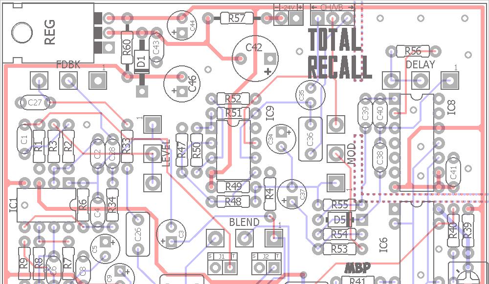
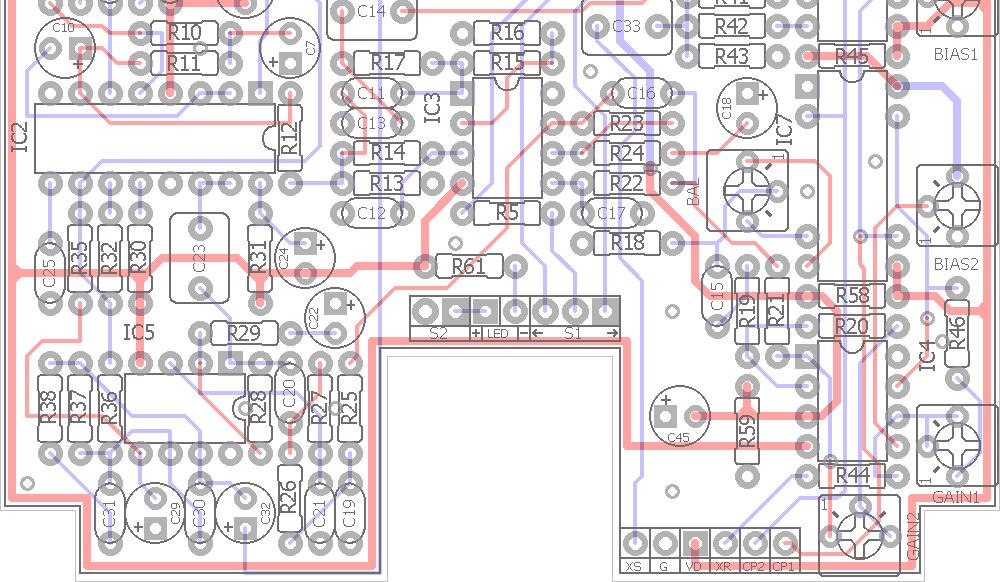
1 Total Recall FX Type: Delay Based on the EHX Deluxe Memory Man 2015 madbeanpedals 3.34" W x 3.875" H Terms of Use: You are free to use purchased Total Recall circuit boards for both DIY and small commercial operations. You may not offer Total Recall boards for resale or as part of a kit in a commercial fashion. Peer to peer re-sale is, of course, okay
2 2
3 B.O.M. Resistors Resistors Caps Caps Diodes R1 2M2 R32 7k5 C1 100n C32 10uF D1 1N4751A R2 100k R33 1k C2 27pF C33 1uF D5 1N4001 R3 22k R34 100k C3 47uF C34 1uF IC R4 47k R35 100k C4 1n2 C35 2u2 BP IC R5 150R R36 240k C5 1uF C36 470n IC2 NE570 R6 100k R37 180k C6 220n C37 2u2 IC R7 200k R38 330k C7 10uF C38 1n IC R8 200k R39 6k8 C8 100n C39 1n IC R9 68k R40 82k C9 1uF C40 240pF IC6 BBD R10 68k R41 2k4 C10 4u7 C41 100n IC7 BBD R11 68k R42 2k4 C11 2n7 C42 470uF IC8 CD4047 R12 24k R43 100k C12 2n7 C43 100n IC R13 51k R44 100k C13 33n C44 10uF Regulator R14 16k R45 6k8 C14 1uF C45 10uF REG LM7915 R15 33k R46 39k C15 220n C46 100uF Trimmer R16 33k R47 15k C16 2n7 GAIN1 100k R17 1k R48 3k3 C17 2n7 GAIN2 100k R18 100k R49 13k C18 4u7 BIAS1 100k R19 680k R50 910k C19 47n BIAS2 100k R20 100k R51 910k C20 2n7 BAL 5k R21 16k R52 120k C21 2n7 Switch R22 16k R53 7k5 C22 4u7 CH/VB On/On R23 33k2 R54 27k C23 1uF Pots R24 24k3 R55 27k C24 1uF DELAY 100kB R25 470R R56 8k2 C25 3n9 FDBK 10kA R26 15k R57 240R C26 470n BLEND 10kB R27 16k R58 100k C27 47n LEVEL 1MA R28 15k R59 100k C28 22n MOD 100kB R29 39k R60 10R C29 1uF R30 11k R61 10k C30 150pF R31 1M5 C31 120pF 3
4 Shopping List Value QTY Type Rating Value QTY Type Rating 10R 1 Metal / Carbon Film 1/2W 27pF 1 Ceramic 25v Min. 150R 1 Metal / Carbon Film 1/4W 120pF 1 Ceramic 25v Min. 240R 1 Metal / Carbon Film 1W 150pF 1 Ceramic 25v Min. 470R 1 Metal / Carbon Film 1/4W 240pF 1 MLCC / Mica - 5% tolerance 25v Min. 1k 2 Metal / Carbon Film 1/4W 1n 2 Film 25v Min. 2k4 2 Metal / Carbon Film 1/4W 1n2 1 Film 25v Min. 3k3 1 Metal / Carbon Film 1/4W 2n7 6 Film 25v Min. 6k8 2 Metal / Carbon Film 1/4W 3n9 1 Film 25v Min. 7k5 2 Metal / Carbon Film 1/4W 22n 1 Film 25v Min. 8k2 1 Metal / Carbon Film 1/4W 33n 1 Film 25v Min. 10k 1 Metal / Carbon Film 1/4W 47n 2 Film 25v Min. 11k 1 Metal / Carbon Film 1/4W 100n 4 Film 25v Min. 13k 1 Metal / Carbon Film 1/4W 220n 2 Film 25v Min. 15k 3 Metal / Carbon Film 1/4W 470n 2 Film 25v Min. 16k 4 Metal / Carbon Film 1/4W 1uF 3 Film 25v Min. 22k 1 Metal / Carbon Film 1/4W 1uF 5 Electrolytic 25v Min. 24k 1 Metal / Carbon Film 1/4W 2u2 1 Electrolytic 25v Min. 24k3 1 Metal / Carbon Film 1/4W 2u2 1 Non-Polar 25v Min. 27k 2 Metal / Carbon Film 1/4W 4u7 3 Electrolytic 25v Min. 33k 2 Metal / Carbon Film 1/4W 10uF 4 Electrolytic 25v Min. 33k2 1 Metal / Carbon Film 1/4W 47uF 1 Electrolytic 25v Min. 39k 2 Metal / Carbon Film 1/4W 100uF 1 Electrolytic 25v Min. 47k 1 Metal / Carbon Film 1/4W 470uF 1 Electrolytic 35v 51k 1 Metal / Carbon Film 1/4W 1N4751A 1 30v Zener 68k 3 Metal / Carbon Film 1/4W 1N k 1 Metal / Carbon Film 1/4W k 10 Metal / Carbon Film 1/4W NE k 1 Metal / Carbon Film 1/4W BBD 2 MN3005 / MN k 1 Metal / Carbon Film 1/4W CD k 2 Metal / Carbon Film 1/4W LM k 1 Metal / Carbon Film 1/4W 100k 4 Bourns 3362P 330k 1 Metal / Carbon Film 1/4W 5k 1 Bourns 3362P 680k 1 Metal / Carbon Film 1/4W On/On 1 SPDT 910k 2 Metal / Carbon Film 1/4W 100kB 2 Alpha Right Angle PCB mount 16mm 1M5 1 Metal / Carbon Film 1/4W 10kA 1 Alpha Right Angle PCB mount 16mm 2M2 1 Metal / Carbon Film 1/4W 10kB 1 Alpha Right Angle PCB mount 16mm 1MA 1 Alpha Right Angle PCB mount 16mm 4
5 5


6 1590BB Tall Drill Guide 7.08" W x 8.1" T 6


7 Stock Wiring Leave enough clearance between the wires and IC6 - IC8 so they do not pick up any clock signal. The indicator LED can be soldered directly to the PCB. If you are using the TRXPN board, refer to that documentation on how to install the expansion board properly. If not, be sure you jumper XS and XR pads together on the lower right of the TR PCB. 7


8 True Bypass Wiring Leave enough clearance between the wires and IC6 - IC8 so they do not pick up any clock signal. The indicator LED can be soldered directly to the PCB. If you are using the TRXPN board, refer to that documentation on how to install the expansion board properly. If not, be sure you jumper XS and XR pads together on the lower right of the TR PCB. 8
9 At long last, the vintage Memory Man project is here! The Total Recall is a clone of the big box DMM which allows you to use either two MN3005 or four MN3008 (if you include the optional expansion board; the TRXPN). With the recent release of the Xvive MN3005 clones this project is suddenly much more viable for builders not lucky enough to get their hands on NOS MN3005 chips (which can go for as much as $40 a piece these days, if you are lucky to get a noncounterfeit one). The good news is that the Xvive chips seem to work very well in the Total Recall. Tests were done comparing them to 2xMN3005 (NOS) and 4xMN3008 (NOS) and they performed very comparable (at least with the two Xvive chips I have on hand). While I won't get into any machinations on precision MOJO between the NOS and new production chips, I am satisfied that the Xvive are fine for this project and the end result sounds great. Perhaps they are even slightly cleaner in output (which is not terribly surprising when you compare recently manufactured IC's with those made 30 years ago). Some important notes before considering this project It's hard. Not the hardest DIY project ever, but pretty challenging. You need to have enough patience to work through the building AND setting it up properly. This means NO BOXING BEFORE ROCKING. You must test this project adequately with a multi-meter AND audio probe before wiring it up in an enclosure. There will be no mercy for tech threads started on the forum by those who ignore this :) It's positive ground and it requires a wall-wart. There's no getting around it. If you want the true vintage DMM, you have to design it to use a wall-wart or AC power plus a transformer. I use, and recommend, an actual EHX 24v supply. It's not too expensive and it works perfectly for the project. And with it, my two builds are dead quiet. You can get the power supply here: Supply/dp/B0042RHT4M. You should be able to use an 18v supply instead of the 24v one listed above, although this has not been tested. You will need to do a couple things: 1) Lower the value of R57 from 240R 1W to something like 22R 1W, and 2) make sure you know what the polarity of your 18v power supply is before hooking it up to the TR PCB! It's expensive. Granted, building your own is still way cheaper than buying a vintage unit, but all in all you can expect to drop $100 or more on this project including the PCBs, power supply and two BBDs. The Total Recall does have some differences with the DMM. I use 1uF film caps instead of non-polar electrolytic (as a matter of personal preference), the "overload LED" circuitry is not used due to space limitations and finally the GAIN1 trimmer is located between BBD stages 3 and 4 instead of 2 & 3 (if using the TRXPN board only, otherwise it is between the two BBD stages when using two MN3005). This last one is the most important. While it does not seem to pose any limitations when using four MN3008, I would not recommend plugging in four MN3005 (as some might be tempted to do) to get 1 second of delay instead of 550ms. Four MN3005 should work for all four BBD spots, but it has not been tested and the extra delay time may prove problematic for the gain recovery. XVIVE MN3005: Controls DELAY: Total delay time from slap-back to approximately 550ms. FDBK: The total number of repeats from one to many to self-oscillation. LEVEL: The input gain of the circuit. This control can create mild overdrive when turned up. BLEND: The dry/wet ratio of guitar and delay. MOD: The depth of modulation applied to the delay signal. The modulation rate is fixed. CH/VB: This switches between chorus and vibrato type modulation. Biasing Controls BIAS1, 2: These trimmers set the input biasing of the BBD chips. GAIN1, 2: These trimmers set the gain recovery after BBD1 and BBD2. BAL: This trimmer balances the two outputs of the second BBD. 9


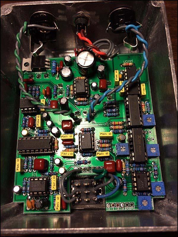
10 Wiring You can wire the Total Recall in either stock or true-bypass fashion. In the stock wiring, the LEVEL control is always active and can be used to boost the bypass signal. Personally, I like this option as the circuit's higher voltage provides a nice clean boost at low LEVEL settings up to a mild overdrive at high settings. If you are a true-bypass purist, use the second wiring diagram. This completely removes the circuit from the bypass mode. Build Notes Take your time and build it right the FIRST time! There are a lot of parts here and the attention and focus you employ in soldering and construction will save you loads of headaches later on. Before doing any voltage tests, make sure you have wired the power correctly. Remember that this is a positive ground circuit! The illustration below shows how the typical DC jack is wired with the EHX power supply for the correct polarity. If you are using a different jack or power supply, plug the PS into your DC jack before wiring it to the PCB and use your multi-meter to verify which lug on the jack is negative DC. Once you have verified polarity on the jack, hook up the PCB to the power supply. Now check the LM7915 regulator to verify that you are getting about -15v output. Once that is complete, disconnect the power and start loading in the ICs. EHX power supply wiring for positive ground. The clearance in the footswitch cut-out area is very tight. If using the typical blue 3PDT footswitches, remove the extra nut that screws into the base of the switch to ensure the board and switch fit properly. Make sure you install the footswitch to your enclosure first, then the PCB (or at least keep the footswitch underneath the PCB if installing both together). If you are doing the stock (non true-bypass) wiring, you can use a DPDT footswitch, if you like. Install the footswitch before the PCB in the enclosure so it fits properly. Mods Increase R2 to 220k for higher input impedance. This can be useful for pickups with hot outputs like humbuckers or actives. Make the Blend pot Audio taper instead of Linear. I prefer audio here because it allows for a larger range of soft delay mix settings. 10


 generated by the CD4047 and processed through the sequential \"bucket\" steps.")
11 Biasing There are two ways to bias the Total Recall. One is by ear and the other is with an oscilloscope. This document will show you how to do it by ear. For scope biasing there are a few guides online the give lots of detail on how to do the procedure. Here is one guide you might find useful for scope calibration: Before biasing, let's understand what we are doing and why. The BBD IC requires a bias voltage applied to its input in order to work properly. This is done via a trimmer set up as a voltage divider connected to the power supply. An audio source is applied to the BBD input (pin7) and the trimmer is adjusted until we get a result on the two outputs of the chip (pins 3 and 4). The output is the delayed signal where the delay time is controlled by the two out-of-phase clock signals (pins 2 and 6) generated by the CD4047 and processed through the sequential "bucket" steps. The two outputs are mixed together and then sent to a gain recovery stage. This helps make up any volume loss introduced by the sequential steps in the BBD (2048 steps for MN3008 and 4096 for MN3005). After the gain recovery, the signal is sent to the next BBD and the same process is repeated. BBD Audio Source Output Mix Gain Recovery Bias Clock Let's compare that to a circuit snippet from the TR schematic. Our audio source comes in at D_IN and goes to pin7 of IC6. BIAS1 is our voltage divider also connected to pin7. CP1 and CP2 are the two clock signals, pins1 and 5 are ground and power resp., pin8 is the Vgg voltage (in this case it is set to -14vDC) and our outputs come from pins 3 and 4. These are mixed with another voltage divider created by R41 - R43. 11
12 The gain recovery stage starts at XR. It is fed through an inverted gain stage with a trimmer to adjust the output volume. Here the biasing is done differently with the bias voltage applied to the non-inverted input of the op-amp. At the outputs, we have a new trimmer, BAL. This trimmer is used to align the two output waveforms for cleanest delay signal obtainable. After the BAL trimmer the signal gets sent to the second and final gain recovery stage. After the second gain recovery stage, the signal is sent through additional filters, the expandor, then mixed to the output of the circuit (not shown). Procedure Tools required: audio source, audio probe. Before you start, remove IC7 if you have it installed. We will bias one BBD at a time. Set your controls as follows: DELAY - full up FDBK - a little less than halfway up MOD - all the way down LEVEL - about 1/3rd up BLEND - doesn't matter (you should leave the circuit output disconnected since we will be audio probing) CH/VB switch - doesn't matter Leave all the trimmers in their halfway position to start. Connect the TR PCB to your power supply. Use an audio source at the input of the circuit (J1). While you can just strum your guitar it might be difficult to make trimmer adjustments at the same time. If you have a looper, record a few single notes a few seconds apart and feed that into the circuit. Or, improvise with something else. Connect your audio probe to either pin3 or pin4 of IC6. Now adjust BIAS1 until you hear delay output. Adjust BIAS1 further until you find the min and max settings where you have clean delay output. Set BIAS1 to approximately the middle point of this range. Now make very small adjustments left and right until you find the spot where the delay output is cleanest and strongest. 12
13 Now connect your audio probe to pin7 of IC4_B. Adjust GAIN1 until the volume output is approximately the same as the volume input on pin7 of IC6 (this balances the signal volumes between the two BBDs). Disconnect the power supply from the circuit and install IC7. Reconnect the power supply. Connect your audio probe to pin3 or 4 of IC7. Do the same type of adjustment to BIAS2 to get clean delay output. Re-connect your audio probe to pin7 of IC4_B. Make any adjustments needed to GAIN1 to reach the same volume output you had before. This part is a bit of fine tuning between GAIN1 and BIAS2 to get the optimal result. Leave the BAL trimmer in the middle position. Connect your audio probe to pin1 of IC4_A. Adjust the GAIN2 trimmer until the output is the same or slightly above the volume input of pin7 on IC6. You are done! If you are using the BBD expansion board, refer to that documentation on how to do this procedure with four BBDs. It is generally the same thing with a few added steps. Mouser Cart For convenience, I have created a cart in Mouser that includes most of the items in the BOM. All the items highlighted in blue are in the cart in the correct quantities. Items in yellow are not included in the cart. Caveat: I have not personally ordered this cart. It was made using my "best guess" on the parts I would order for this project. Also, this cart does not include the quantities needed for the TRXPN board. However, those parts and values are already listed in the Mouser cart. Simply put in the additional quantities needed for the resistors, caps and trimmers for the TRXPN board. 13
14 Voltages Using the EHX 24v supply measuring / no load IC1 IC2 IC3 IC4 IC DC NE570 DC 4558 DC 4558 DC 4558 DC IC6 IC7 IC8 IC9 REG BBD DC BBD DC CD4047 DC 4558 DC LM7915 DC vaires I G vaires O vaires
15 15
Dirtbaby FX TYPE: Delay Based on the EHX DMM 2016 madbeanpedals
 Dirtbaby FX TYPE: Delay Based on the EHX DMM 2016 madbeanpedals 3.325 W x 2.325 H Terms of Use: You are free to use purchased circuit boards for both DIY and small commercial operations. You may not offer
Aquaboy FX TYPE: Delay Based on the Boss DM madbeanpedals
 Aquaboy FX TYPE: Delay Based on the Boss DM-2 2016 madbeanpedals 2.3 W x 3.125 H 1.29.17 Correction see page 6. Note: the M pad by the Delay pot is for modulation control (see the AB_MOD documentation
VFE Choral Reef. FX TYPE: Chorus Images VFE and MBP Project Doc madbeanpedals Aug. 2 nd update see pg W x 2.05 H
 VFE Choral Reef FX TYPE: Chorus Images VFE and MBP Project Doc madbeanpedals Aug. 2 nd update see pg.4 2.17 W x 2.05 H Terms of Use: These projects are intended for DIY use only and may not be used in
Cave Dweller 2015 edition FX Type: Delay 2015 madbeanpedals
 Cave Dweller 2015 edition FX Type: Delay 2015 madbeanpedals 1.3" W x 1.975" H (main board) Previous Version: http://www.madbeanpedals.com/projects/cavedweller/cavedweller_drill.zip Terms of Use: You are
Stage Fright 2015 edition FX TYPE: Phaser Based on the Maestro Phaser 2015 madbeanpedals
 Stage Fright 2015 edition FX TYPE: Phaser Based on the Maestro Phaser 2015 madbeanpedals 2.3" W x 3.45" H Previous Version: http://www.madbeanpedals.com/stagefright/stagefright.zip Terms of Use: You are
FREEKOUT FX TYPE: Ring Modulator Based on the EHX Frequency Analyzer 2015 madbeanpedals
 FREEKOUT FX TYPE: Ring Modulator Based on the EHX Frequency Analyzer 2015 madbeanpedals 2.3 W x 3.025 H This project requires an 18v 100mA (or more) center tip negative power supply. I recommend the Dunlop
Weener Wah FX TYPE: Wah Wah Based on the Clyde McCoy 2016 edition madbeanpedals
 Weener Wah FX TYPE: Wah Wah Based on the Clyde McCoy 2016 edition madbeanpedals 1.95 W x 2.275 H Terms of Use: You are free to use purchased WeenerWah circuit boards for both DIY and small commercial operations.
2015 ed. FX Type: Univibe 2015 madbeanpedals W x 3.29 H
 Harbinger One 2015 ed. FX Type: Univibe 2015 madbeanpedals 3.25 W x 3.29 H Harbinger One PCBs purchased form madbeanpedals may be used for small amounts of commercial building without prior consent. Keep
2.15 W x 1.95 H. Changes to the 2015 edition
 NOM NOM FX Type: Filter 2015 edition Based on the MXR Phase 90 2015 madbeanpedals Download the previous version documentation here: http://www.madbeanpedals.com/projects/nomnom/nomnom.zip 2.15 W x 1.95
Dig Dug madbeanpedals FX Type: Sequencer W x 3.25 H
 Dig Dug2 2015 madbeanpedals FX Type: Sequencer 4.15 W x 3.25 H B.O.M. Resistors Caps Diodes R1 1M C1 100n D1 1N5817 R2 1M C2 220n D2 - D4 1n914 R3 10k C3 15n LED1-8 3mm Red R4 330k C4 2n2 PATT 3mm Red
Blues King. FX TYPE: Overdrive Images VFE and MBP Project Doc madbeanpedals W x H
 Blues King FX TYPE: Overdrive Images VFE and MBP Project Doc madbeanpedals 2.17 W x 2.025 H Note: Use the values listed on the image above not the values indicated on the silk-screen of the PCB. Some values
Build Guide CascadiA. GeFet Preamp
 Build Guide CascadiA GeFet Preamp Disclaimery stuff: This project is meant to be assembled by fellow DIYers from the Madbean forum and should only be used for the forces of good. Any other uses prohibited
Triumvirate. FX TYPE: Multi-Band Distortion Images VFE and MBP Project Doc madbeanpedals W x 2.01 H
 Triumvirate FX TYPE: Multi-Band Distortion Images VFE and MBP Project Doc madbeanpedals 2.17 W x 2.01 H Note: Use the values listed on the image above not the values indicated on the silk-screen of the
FX Type: Distortion 1.95 W x H Terms of Use: Slow Loris Slow Loris
 Slow Loris 2015 edition madbeanpedals FX Type: Distortion Based on the ProCo Rat Changes for the 2015 edition: Slight layout adjustments. No circuit changes. Previous version: http://www.madbeanpedals.com/projects/slowloris/docs/slowloris.zip
VFE Switching Board madbeanpedals Some images 2017 VFE Pedals, used with permission 8.7 update: see pg W x 1.33 H
 VFE Switching Board 2017 madbeanpedals Some images 2017 VFE Pedals, used with permission 8.7 update: see pg. 7 2.16 W x 1.33 H The VFE Switching Board and micro-controller are included with all the VFE
Standard JFET input buffer and Standard NPN Output buffer
 Board Standard JFET input buffer and Standard NPN Output buffer By PCB Guitar mania Mania Project link The buffers are normally added into a circuit to prevent loading and loss of definition of the guitar
Tractor BEam. FX TYPE: Phaser Images VFE and MBP Project Doc madbeanpedals
 Tractor BEam FX TYPE: Phaser Images VFE and MBP Project Doc madbeanpedals 2.17 W x 2.02 H Note: This project is built on the Enterprise PCB. It s the same circuit as the Tractor Beam with a few value modifications.
Electric Druid Flangelicious Flanger Project
 Electric Druid Flangelicious Flanger Project (Using either 4KNOBFLANGE or MULTIFLANGE chips) Overview! 2 Build Instructions! 2 Populate the PCB! 2 1N4148 Diodes! 2 Resistors! 2 Cup of tea and soldering
Multiwave. Guitar Synthesizer. Build Document last updated november 2018 Version
 Multiwave Guitar Synthesizer Build Document last updated november 2018 Version 1.0 2018 The Multiwave is a guitar controlled oscillator with 3 different waveshapes: saw, triangle and square. Combined,
Build Your Own Clone Li l Analog Chorus Kit Instructions
 Build Your Own Clone Li l Analog Chorus Kit Instructions Warranty: BYOC, Inc. guarantees that your kit will be complete and that all parts and components will arrive as described, functioning and free
The Triplet. FX TYPE: Comp+Oct+Dist Images VFE and MBP Project Doc madbeanpedals W x H
 The Triplet FX TYPE: Comp+Oct+Dist Images VFE and MBP Project Doc madbeanpedals 2.17 W x 2.025 H Note: Use the values listed on the image above not the values indicated on the silk-screen of the PCB. Some
Mobius Strip. FX TYPE: Dual Delay Images VFE and MBP Project Doc madbeanpedals W x H
 Mobius Strip FX TYPE: Dual Delay Images VFE and MBP Project Doc madbeanpedals 2.17 W x 2.025 H Note: Use the values listed on the image above not the values indicated on the silk-screen of the PCB. Some
BYOC Vibrato Kit Instructions BA662A version
 BYOC Vibrato Kit Instructions BA662A version Please read these instructions very thoroughly before building even if you are an experience builder. Because of the layout, there is a certain order which
BYOC Vibrato Kit Instructions BA6110 version
 BYOC Vibrato Kit Instructions BA6110 version Please read these instructions very thoroughly before building even if you are an experience builder. Because of the
Super Nova Distortion
 Super Nova Distortion The Super Nova is a reworking of the Marshall Guv'nor circuit. It uses the same gain structure as its parent design but is EQ'ed quite differently. The basic tone from the gain stages
TLN-428 Voltage Controlled State Variable Filter
 The Tellun Corporation TLN-428 Voltage Controlled State Variable Filter User Guide, Rev. 1.1 Scott Juskiw The Tellun Corporation scott@tellun.com TLN-428 User Guide Revision 1.1 March 16, 2003 Introduction
Build Your Own Clone British Blues Overdrive Kit Instructions
 Build Your Own Clone British Blues Overdrive Kit Instructions Warranty: BYOC, LLC guarantees that your kit will be complete and that all parts and components will arrive as described, functioning and free
Guitarpedalkits.com Overdrive Pedal Build Instructions
 Page 1 Guitarpedalkits.com Overdrive Pedal Build Instructions Follow the instructions in this guide to build your very own DIY overdrive pedal from GuitarPedalKits.com. If you re a first time builder,
The Tellun Corporation. TLN-442 Voltage Controlled Lowpass Filter. User Guide, Rev Scott Juskiw The Tellun Corporation
 The Tellun Corporation TLN-442 Voltage Controlled Lowpass Filter User Guide, Rev. 1.1 Scott Juskiw The Tellun Corporation scott@tellun.com TLN-442 User Guide Revision 1.1 March 15, 2003 Introduction The
Blueprint. FX TYPE: Delay Images VFE and MBP Project Doc madbeanpedals W x H
 Blueprint FX TYPE: Delay Images VFE and MBP Project Doc madbeanpedals 2.17 W x 2.025 H Note: Use the values listed on the image above not the values indicated on the silk-screen of the PCB. Some values
Build Your Own Clone Crown Jewel Kit Instructions
 Build Your Own Clone Crown Jewel Kit Instructions Warranty: BYOC, Inc. guarantees that your kit will be complete and that all parts and components will arrive as described, functioning and free of defect.
PCB by 1776 Effects/JRM 2013 Circuit Design by Jon Patton
 Cardinal Tremolo PCB by 1776 Effects/JRM 2013 Circuit Design by Jon Patton The Cardinal Tremolo is a transistor and vactrol implementation of the Harmonic Tremolo. It resembles the harmonic tremolo from
Build Your Own Clone Chancellor Kit Instructions
 Build Your Own Clone Chancellor Kit Instructions Warranty: BYOC, Inc. guarantees that your kit will be complete and that all parts and components will arrive as described, functioning and free of defect.
Build Your Own Clone Classic Overdrive Kit Instructions
 Build Your Own Clone Classic Overdrive Kit Instructions Warranty: BYOC, LLC guarantees that your kit will be complete and that all parts and components will arrive as described, functioning and free of
VFE Merman. FX TYPE: Overdrive Images VFE and MBP Project Doc madbeanpedals W x H
 VFE Merman FX TYPE: Overdrive Images VFE and MBP Project Doc madbeanpedals 2.17 W x 2.025 H Note: Use the values listed on the image above not the values indicated on the silk-screen of the PCB. Some values
INTO THE UNKNOWN Build Document last updated may 2016 Version
 INTO THE UNKNOWN Build Document last updated may 2016 Version 1.0 2015 'Into the Unknown Guitar Synthesizer Deluxe' is a CMOS based fuzz centered around the CD4046 PLL (phase locked loop) chip and a CD4015
N3ZI Kits General Coverage Receiver, Assembly & Operations Manual (For Jun 2011 PCB ) Version 3.33, Jan 2012
 Version 3.33, Jan 2012") N3ZI Kits General Coverage Receiver, Assembly & Operations Manual (For Jun 2011 PCB ) Version 3.33, Jan 2012 Thank you for purchasing my general coverage receiver kit. You can use the photo above as a
N3ZI Kits General Coverage Receiver, Assembly & Operations Manual (For Jun 2011 PCB ) Version 3.33, Jan 2012 Thank you for purchasing my general coverage receiver kit. You can use the photo above as a
DIY Function Generator XR2206
 DIY Function Generator XR2206 20Hz 100KHz http://radiohobbystore.com Components List: Resistors: R1, R2 1% Metal Film 5K1 R4 1% Metal Film 10K R5 1% Metal Film 3K R10 5% Carbon Film 10R R3, R9 Potentiometer
Build Your Own Clone Li l Reverb Kit Instructions
 Build Your Own Clone Li l Reverb Kit Instructions Warranty: BYOC, Inc. guarantees that your kit will be complete and that all parts and components will arrive as described, functioning and free of defect.
NEW WAVE CV GENERATOR Build Document last updated september 2017 for PCB version 1.0
 NEW WAVE CV GENERATOR Build Document last updated september 2017 for PCB version 1.0 The New Wave is a Control Voltage Generator. It has two LFO's (low frequency oscillators) and four different output
Build Your Own Clone Mega Chorus & Vibrato Kit Instructions
 Build Your Own Clone Mega Chorus & Vibrato Kit Instructions Warranty: BYOC, Inc. guarantees that your kit will be complete and that all parts and components will arrive as described, functioning and free
Build Your Own Clone Mouse Kit Instructions
 Build Your Own Clone Mouse Kit Instructions Warranty: BYOC, Inc. guarantees that your kit will be complete and that all parts and components will arrive as described, functioning and free of defect. Soldering,
Build Your Own Clone Kuzco Jr. Kit Instructions
 Build Your Own Clone Kuzco Jr. Kit Instructions Warranty: BYOC, Inc. guarantees that your kit will be complete and that all parts and components will arrive as described, functioning and free of defect.
Build Your Own Clone Li l Echo Kit Instructions
 Build Your Own Clone Li l Echo Kit Instructions Warranty: BYOC, Inc. guarantees that your kit will be complete and that all parts and components will arrive as described, functioning and free of defect.
Electric Druid 4 second Digital Delay Project
 Electric Druid 4 second Digital Delay Project Overview! 2 Build Instructions! 2 Populate the PCB! 2 Resistors! 2 Cup of tea and soldering check! 3 Power protection diode! 4 Ground link wire! 4 IC sockets!
Building a Bitx20 Version 3
 Building a Bitx20 Version 3 The board can be broken into sections and then built and tested one section at a time. This will make troubleshooting easier as any problems will be confined to one small section.
Jour de FET Mounting instructions.
 Jour de FET Mounting instructions. Summary Important notice. What's in the kit? What you'll need. Soldering on the pcb. Wiring the pedal. Test the board. Debugging chapter. Hacks!!! 3 4 4 3 5 6 Copyright
Build Your Own Clone The Swede Kit Instructions
 Build Your Own Clone The Swede Kit Instructions Warranty: BYOC, Inc. guarantees that your kit will be complete and that all parts and components will arrive as described, functioning and free of defect.
MoWAH v3. Board Dimensions (W x H) 2.05 x 1.95 ca. 52.1mm x 49.6mm
 2.05 x 1.95 ca. 52.1mm x 49.6mm") MoWAH v3 Board Dimensions (W x H) 2.05 x 1.95 ca. 52.1mm x 49.6mm The above image can be downloaded from http://i647.photobucket.com/albums/uu198/tonmann/guitarpcb%20boards/mowahv3layout.png Printing at
MoWAH v3 Board Dimensions (W x H) 2.05 x 1.95 ca. 52.1mm x 49.6mm The above image can be downloaded from http://i647.photobucket.com/albums/uu198/tonmann/guitarpcb%20boards/mowahv3layout.png Printing at
BYOC Analog Delay Kit Instructions
 BYOC Analog Delay Kit Instructions Please read through the instructions completely before beginning this project. This is one of our most difficult kits and it is a little different than other BYOC kits,
Build Your Own Clone 27V Boost Kit Instructions
 Build Your Own Clone 27V Boost Kit Instructions Warranty: BYOC, Inc. guarantees that your kit will be complete and that all parts and components will arrive as described, functioning and free of defect.
Penrose Quantizer Assembly Guide
 Penrose Quantizer Assembly Guide Schematic and BOM The schematic can be found here: www.sonic-potions.com/public/penrosequantizerschematic.pdf The BOM is available at google docs: Link to BOM Prepare the
Build Your Own Clone Tremolo Kit Instructions
 Build Your Own Clone Tremolo Kit Instructions Warranty: BYOC, LLC guarantees that your kit will be complete and that all parts and components will arrive as described, functioning and free of defect. Soldering,
BMC052. Chordizer Last updated
 BMC052. Chordizer Last updated 8-27-2017 If you have any questions, or need help trouble shooting, please e-mail Michael@Bartonmusicalcircuits.com I Overview/Controls/Inputs/Outputs II Schematic III Construction
BMC017. 2LFOSH Last updated I Features II Schematics III Construction
 BMC017. 2LFOSH Last updated 12-3-2013 I Features II Schematics III Construction I. Features The 2LFOSH module is a combination of three different modules on one board, designed to be easy to be easy to
Build Your Own Clone Analog Chorus Kit Instructions
 Build Your Own Clone Analog Chorus Kit Instructions Warranty: BYOC, Inc. guarantees that your kit will be complete and that all parts and components will arrive as described, functioning and free of defect.
Axis Fuzz Kit Building Manual
 Axis Fuzz Kit Building Manual Effect Pedal Kits: Axis Fuzz The Axis Fuzz Kit is based in the Roger Mayer Axis Fuzz, the effect pedal responsible for Jimi Hendrix sound in Axis Bold As Love. What else is
Build Your Own Clone Li l Comp Kit Instructions
 Build Your Own Clone Li l Comp Kit Instructions Warranty: BYOC, Inc. guarantees that your kit will be complete and that all parts and components will arrive as described, functioning and free of defect.
Value Location Qty Transistors 2N5485 Q1, Q2, 4 Q3, Q4 2N5087 Q5 1. Trim Pots 250k VTRIM 1. Potentiometers C500k Speed 1. Toggle Switch On/On Vibe 1
 P-90 BUILD INSTRUCTIONS Thank you for your purchase of our P-90 kit! We have completely redesigned our entire line of kits to be the most user friendly, while still maintaining their same great sound!
Build Your Own Clone Reverb Kit Instructions
 Build Your Own Clone Reverb Kit Instructions Warranty: BYOC, LLC guarantees that your kit will be complete and that all parts and components will arrive as described, functioning and free of defect. Soldering,
SIMPLE DIRECT DRIVE DESULPHATOR/ DESULFATOR KIT INSTRUCTIONS
 SIMPLE DIRECT DRIVE DESULPHATOR/ DESULFATOR KIT INSTRUCTIONS Parts List C1 470uF/ 25V 1off C2 C5 0.1uF/ 50V 4off C6 C9 0.01uF/ 50V 4off D1 12V/ 1.3W zener 1off Q1 2N2907 1off Q2 Q4 IRFB3307 3off R1 510R/
STEP 0 Prepare the Materials.
 How to Build a Germanium Fuzz Guitar Effect. This document will guide you to build and test your Germanium Fuzz guitar pedal. With all the materials on hand, it takes around 2-4 hours to build it. Try
R*S Stereo Mixer V1.2
 R*S Stereo Mixer V1.2 The Random*Source Equal Power Stereo-Mixer is a voltage controlled stereo mixer / panner / VCA based on 4 high-end THAT2180 blackmer VCAs, designed to emulate the behavior of Serge
J HAIBLE DUAL WASP VCF (Euro)
") J HAIBLE DUAL WASP VCF (Euro) Jürgen Haible s WASP Filter adaption of the famous CMOS VCF introduced some unique features, in particular a distortion stage. The R*S version takes this a step further by
J HAIBLE DUAL WASP VCF (Euro) Jürgen Haible s WASP Filter adaption of the famous CMOS VCF introduced some unique features, in particular a distortion stage. The R*S version takes this a step further by
Build Your Own Clone Divided Octave Kit Instructions
 Build Your Own Clone Divided Octave Kit Instructions Warranty: BYOC, Inc. guarantees that your kit will be complete and that all parts and components will arrive as described, functioning and free of defect.
D Lay by GuitarPCB. We also carry the D'lay Tap Tempo board available separately in our SHOP. Not mandatory.
 D Lay by GuitarPCB Based on an Analog Style Delay but with added Delay time of up to 350-400ms, or slightly longer depending on quality of the PT2399 chip you use. Many months and trials went into perfecting
Assembly Instructions for the FRB FET FM 70 Watt Amp
 Assembly Instructions for the FRB FET FM 70 Watt Amp 1.) Orient the circuit board with the diagram 2.) Use a narrow chisel tip 25-30 watt soldering iron for assembly 3.) All the small parts are taped onto
GCI BRUTALIST JR. BUILD GUIDE
 GCI BRUTALIST JR. BUILD GUIDE The Brutalist Jr. is the DIY little brother to the GCI Brutalist, a high powered distortion pedal loosely based on the Providence Stampede SDT-1. It runs on 9v DC power or
Build Your Own Clone Li l Pony Kit Instructions
 Build Your Own Clone Li l Pony Kit Instructions Warranty: BYOC, Inc. guarantees that your kit will be complete and that all parts and components will arrive as described, functioning and free of defect.
LunarBlast v1.0. Optical Tremolo. Description:
 LunarBlast v1.0 Optical Tremolo Description: Based on the venerable DIY Tremulus Lune classic circuit, www.madbean.com forum member CultureJam created this awesome sounding tremolo dubbed the Shoot the
Bi-Directional DC Motor Speed Controller 5-32Vdc (3166v2)
") General Guidelines for Electronic Kits and Assembled Modules Thank you for choosing one of our products. Please take some time to carefully read the important information below concerning use of this product.
General Guidelines for Electronic Kits and Assembled Modules Thank you for choosing one of our products. Please take some time to carefully read the important information below concerning use of this product.
Manual Version July 2007
 Manual Version 1.2 - July 2007 Page 1 Table of Contents Section1: M3 Phono Board Build...3 Phono Board Parts List...3 Preparation...4 Fitting the Valve Bases...6 Installing the Resistors...7 Starting the
Code Practice Oscillator (CPO) For kit building instructions turn to Page 3.
 For kit building instructions turn to Page 3.") Code Practice Oscillator (CPO) For kit building instructions turn to Page 3. Overview Many thanks for your purchase of this code practice oscillator or CPO, this guide is intended to allow you to quickly
Code Practice Oscillator (CPO) For kit building instructions turn to Page 3. Overview Many thanks for your purchase of this code practice oscillator or CPO, this guide is intended to allow you to quickly
Build Your Own Clone B.G. Fuzz Kit Instructions
 Build Your Own Clone B.G. Fuzz Kit Instructions Warranty: BYOC, Inc. guarantees that your kit will be complete and that all parts and components will arrive as described, functioning and free of defect.
Build Your Own Clone Green Pony Kit Instructions
 Build Your Own Clone Green Pony Kit Instructions Warranty: BYOC, Inc. guarantees that your kit will be complete and that all parts and components will arrive as described, functioning and free of defect.
EE43 43/100 Fall Final Project: 1: Audio Amplifier, Part Part II II. Part 2: Audio Amplifier. Lab Guide
 EE 3/00 EE FINAL PROJECT PROJECT:AN : AUDIO AUDIO AMPLIFIER AMPLIFIER Part : Audio Amplifier Lab Guide In this lab we re going to extend what you did last time. We re going to use your AC to DC converter
THE GREEN CURRANT TREMOLO Build Document last updated june 2017 for PCB version 1.5
 THE GREEN CURRANT TREMOLO Build Document last updated june 2017 for PCB version 1.5 The Green Currant tremolo is a very percussive and vibey tremolo based around the TDA7052A amplifier chip. It splits
Glue Fuzz Mounting instructions.
 Glue Fuzz Mounting instructions. Index Important notice. 2 What's in the kit? 3 What you'll need. 4 Soldering on the pcb. 4 Wiring the pedal. 11 Test the board. 12 Debugging chapter. 13 Copyright Zorg
The ROSE 80 CW Transceiver (Part 1 of 3)
") Build a 5 watt, 80 meter QRP CW Transceiver!!! Page 1 of 10 The ROSE 80 CW Transceiver (Part 1 of 3) Build a 5 watt, 80 meter QRP CW Transceiver!!! (Designed by N1HFX) A great deal of interest has been
Build a 5 watt, 80 meter QRP CW Transceiver!!! Page 1 of 10 The ROSE 80 CW Transceiver (Part 1 of 3) Build a 5 watt, 80 meter QRP CW Transceiver!!! (Designed by N1HFX) A great deal of interest has been
Music Thing Modular SimpleEQ Construction Guide (1206 version)
") Music Thing Modular SimpleEQ Construction Guide (1206 version) Page 1 Useful Links The latest version of this doc and BOM can always be found at http://thonk.co.uk/documents/eq/ A build thread on the Muffwiggler
Music Thing Modular SimpleEQ Construction Guide (1206 version) Page 1 Useful Links The latest version of this doc and BOM can always be found at http://thonk.co.uk/documents/eq/ A build thread on the Muffwiggler
presents FX TYPE: VIBRATO m2011 madbeanpedals Release date: revised see highlighted notes Thanks, Paul!
 http://www.madbeanpedals.com presents Quadrovibe FX TYPE: VIBRATO m2011 madbeanpedals Release date: 07.1.11 revised 10.26 see highlighted notes Thanks, Paul! The Quadrovibe is a unique Vibrato/Tremolo
the DON classics U76 (blue face - rev A) ASSEMBLY GUIDE REV: 1:04
 ASSEMBLY GUIDE REV: 1:04") the DON classics www.thedonclassics.com U76 (blue face - rev A) ASSEMBLY GUIDE REV: 1:04 QUICK ASSEMBLY GUIDE 9 STEPS TO COMPRESSOR HEAVEN! 1. 2. 3. 4. 5. 6. 7. 8. 9. Solder parts on PCB Wire pots Solder
the DON classics www.thedonclassics.com U76 (blue face - rev A) ASSEMBLY GUIDE REV: 1:04 QUICK ASSEMBLY GUIDE 9 STEPS TO COMPRESSOR HEAVEN! 1. 2. 3. 4. 5. 6. 7. 8. 9. Solder parts on PCB Wire pots Solder
Value Location Qty Potentiometers C1M Distortion 1 A10k Volume 1. Footswitch 3PDT SW1 1. Jacks 1/4 Mono 2 DC Power 1
 Distortion BUILD INSTRUCTIONS Thank you for your purchase of our Distortion+ kit! We have completely redesigned our entire line of kits to be the most user friendly, while still maintaining their same
Wiring Manual NEScaf April 2010 (August 2006)
") Wiring Manual NEScaf April 2010 (August 2006) Switched Capacitor Audio Filter The NEScaf is a switched capacitor audio filter (acronym SCAF) built around a building-block type filter chip. The NEScaf will
Wiring Manual NEScaf April 2010 (August 2006) Switched Capacitor Audio Filter The NEScaf is a switched capacitor audio filter (acronym SCAF) built around a building-block type filter chip. The NEScaf will
CV Arpeggiator Rev 1. Last updated
 CV Arpeggiator Rev Last updated 6--20 The CV Arpeggiator is a modular synth project used for creating arpeggios of control voltage. It utilizes a custom programmed PIC 6F685 micro controller. It includes
Build Your Own Clone Silver Pony Kit Instructions
 Build Your Own Clone Silver Pony Kit Instructions Warranty: BYOC, Inc. guarantees that your kit will be complete and that all parts and components will arrive as described, functioning and free of defect.
H BRIDGE INVERTER. Vdc. Corresponding values of Va and Vb A+ closed, Va = Vdc A closed, Va = 0 B+ closed, Vb = Vdc B closed, Vb = 0 A+ B+ A B
 1. Introduction How do we make AC from DC? Answer the H-Bridge Inverter. H BRIDGE INVERTER Vdc A+ B+ Switching rules Either A+ or A is always closed, but never at the same time * Either B+ or B is always
! Memory Lane 2! Analog delay with tap tempo and dual independent delay times
 ! Memory Lane 2! Analog delay with tap tempo and dual independent delay times User Manual v1.00 May 2, 2008 Memory Lane 2 user manual v1.00 1 Introduction Thank you for purchasing a Diamond Memory Lane
R*S Stereo Mixer V1.3
 R*S Stereo Mixer V1.3 The Random*Source Equal Power Stereo-Mixer is a voltage controlled stereo mixer / panner / VCA based on 4 high-end THAT2180 blackmer VCAs, designed to emulate the behavior of Serge
BassAce - Midi Bass Synthesizer. BassAce Features
 Untitled Document BassAce - Midi Bass Synthesizer The BassAce is a small midi-synth based loosely on the TB303. It can be built many different ways. Depending on how it's configured it can be anything
The Tellun Corporation. TLN-861 Dunsel. User Guide, Rev Scott Juskiw The Tellun Corporation
 The Tellun Corporation TLN-861 Dunsel User Guide, Rev. 1.0 Scott Juskiw The Tellun Corporation scott@tellun.com TLN-861 User Guide Revision 1.0 August 31, 2006 1. Introduction The TLN-861 Dunsel is a collection
Rangemaster Treble Booster Kit Building Manual
 Rangemaster Treble Booster Kit Building Manual Effect Pedal Kits: Rangemaster Treble Booster The Dallas Rangemaster is the most famous treble booster effect pedal, and it was the first pedal of its kind.
EA TREMELO v3. Board Dimensions (W x H) 1.53 x 1.83 ca. 38.7mm x 46.4mm
 1.53 x 1.83 ca. 38.7mm x 46.4mm") EA TREMELO v3 Our easiest and best small Tremolo build with On-board Modifications and Wiring Options. A flashing LED mod that shows the speed of the LFO has been added. You may mount this either Internal
EA TREMELO v3 Our easiest and best small Tremolo build with On-board Modifications and Wiring Options. A flashing LED mod that shows the speed of the LFO has been added. You may mount this either Internal
WHISTLE ROCK AUDIO ML12 PSU KIT/PCB
 WHISTLE ROCK AUDIO ML12 PSU KIT/PCB TABLE OF CONTENTS 1. INTRODUCTION Page 3 2. BILL OF MATERIAL Page 4 3. ALTERNATE RESISTOR VALUES Page 5 4. ASSEMBLY GUIDE Page 6 to 11 5. CONNECTIONS Page 12 6. SETUP
Build Your Own Clone Silver Pony 2 Kit Instructions
 Build Your Own Clone Silver Pony 2 Kit Instructions Warranty: BYOC, Inc. guarantees that your kit will be complete and that all parts and components will arrive as described, functioning and free of defect.
nonlinearcircuits QUO/LPF build notes version 2 11 April 2014
 nonlinearcircuits QUO/LPF build notes version 2 11 April 2014 This circuit is based on the 4 pole LPF in Electronotes 41, tho has been subject to a number of tweaks and prods to bring it to where it is
Build Your Own Clone Classic Phaser Kit Instructions
 Build Your Own Clone Classic Phaser Kit Instructions Warranty: BYOC, Inc. guarantees that your kit will be complete and that all parts and components will arrive as described, functioning and free of defect.
RadiØKit Μ CW HAM RADIO TRANSCEIVER KIT. Assembly and operating manual
 RadiØKit-120 20Μ CW HAM RADIO TRANSCEIVER KIT Assembly and operating manual Boreiou Ipirou 78 Kolonos Athens- Greece - 10444 Tel: 210.5150527 210.5132673 www.freebytes.com Thank you for buying RadiØKit-1,
Build Your Own Clone Li l Beaver (Ram s Head) Kit Instructions
 Kit Instructions") Build Your Own Clone Li l Beaver (Ram s Head) Kit Instructions Warranty: BYOC, Inc. guarantees that your kit will be complete and that all parts and components will arrive as described, functioning and
Build Your Own Clone Li l Beaver (Ram s Head) Kit Instructions Warranty: BYOC, Inc. guarantees that your kit will be complete and that all parts and components will arrive as described, functioning and
EZ1290 Assembly Guide
 EZ190 Assembly Guide Capacitors This picture shows the different types of capacitors used and how they are symbolized and mounted on the PCB. Don t mess this up or bad things will happen!!! Electrolytic