the DON classics U76 (blue face - rev A) ASSEMBLY GUIDE REV: 1:04
|
|
|
- Barry Wilkerson
- 6 years ago
- Views:
Transcription
1 the DON classics U76 (blue face - rev A) ASSEMBLY GUIDE REV: 1:04
2 QUICK ASSEMBLY GUIDE 9 STEPS TO COMPRESSOR HEAVEN! Solder parts on PCB Wire pots Solder transformers and meter Place PCBs in metal work Insert transistors & op-amp Initial test Match and insert FETs Test and calibrate Attach face plate & knobs Compress!
3 Frequently Asked Questions (FAQ) Q. A. What is included in the kit? Q. A. What other orders do I need to make? Q. A. Is there a schematic that would be useful? Q. Which Lunchbox can I use this with? API? GDIY? A. Both! If you wish to use this with a GDIY lunchbox then you do not need to cut the extra gold pins off. Everything included on this page is included in the kit from us. You need to make 2 other orders as detailed on this page. For reference you can download the U76 schematic from the DON classics website. U76 Schematic PCB designations reference this. If you wish to use a normal API standard lunchbox, you must cut the extra gold pins off. Q. Who can build this? A. You! As long as you have patience and are thorough in your work, anyone can build this classic compressor. There's lots of support and information and it is tried and tested. Q. How close to the original does it sound? A. Spot on. We have chosen not to do any new and improved updates on a circuit that sounds so good. We have chosen the same parts that was used originally and recommend this. The only change we've made is to use the meter circuit off the rev F version as it's not in the signal path and is more stable so won't drift as much over time. It's also on PCB pins so you can remove it to check if you don't believe me ;)
 and work up to the larger parts (caps etc.) Solder sockets for transistors on all boards apart from the PS16Vto30V PCB. Fit bottom parts first as they'll be less room to solder up top.")
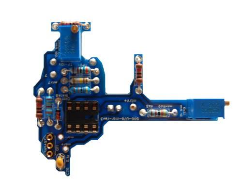
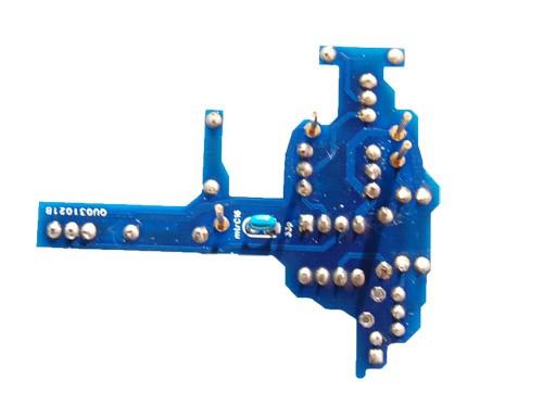
4 1. Solder parts on PCB Insert all parts on to the PCB as marked on the silkscreen. Silkscreens can be downloaded here: silkscreens.zip TIPS: Start with smaller parts (resistors etc.) and work up to the larger parts (caps etc.) Solder sockets for transistors on all boards apart from the PS16Vto30V PCB. Fit bottom parts first as they'll be less room to solder up top. dlyr1 is 62k (as stated inside the box, not outside the box!) R64 solder before the switches for more room 2k trim pot with screw on the end needs to be on the Meter board 2k trim pot with screw on top needs to be on the Control Amp board Where there is a choice of metal film or carbon comp.. always fit the carbon comp on the Control Amp PCB and Main PCB. Leave the metal film for Meter PCB or part designations beginning with dly Solder U1e, Q3e and U2f to the bottom of the board for more room Make sure no parts on the bottom of the PS16Vto30V or Main PCBs extend over the 6.35mm standoffs. Make sure no metal legs protrude over the edge of the PS16Vto30V PCB Place green molexs on the CA board and PS16Vto30V PCBs. Not Main PCB. Place transistor sockets on all DC/DC converter legs before soldering to PCB... (as shown below) PCBs should end up looking like this...
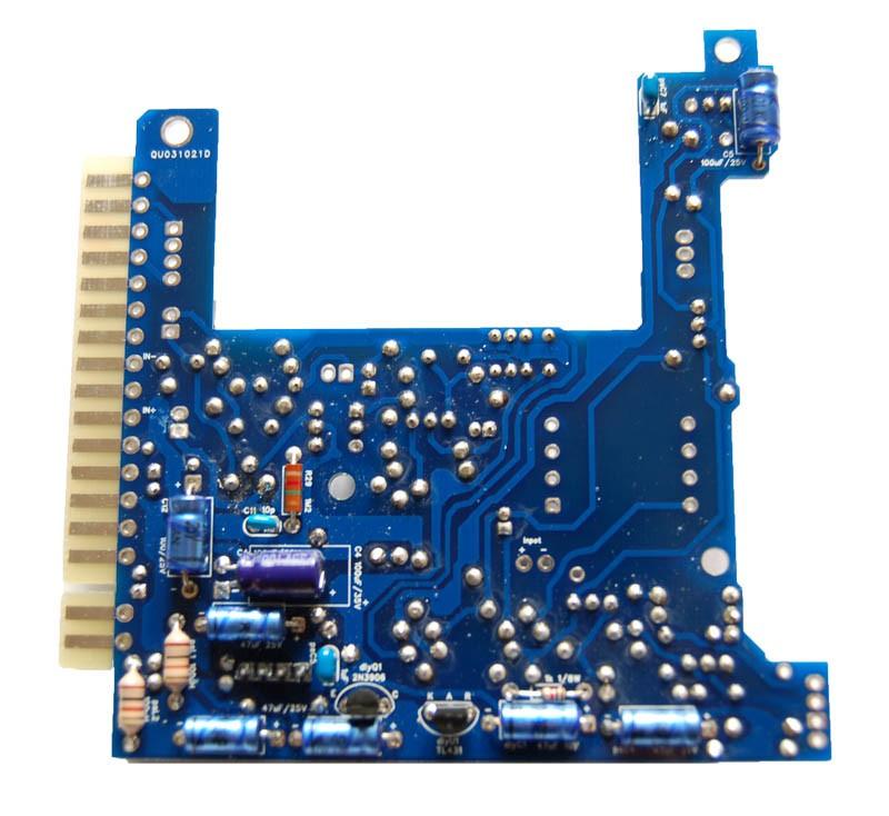
5 Main PCB

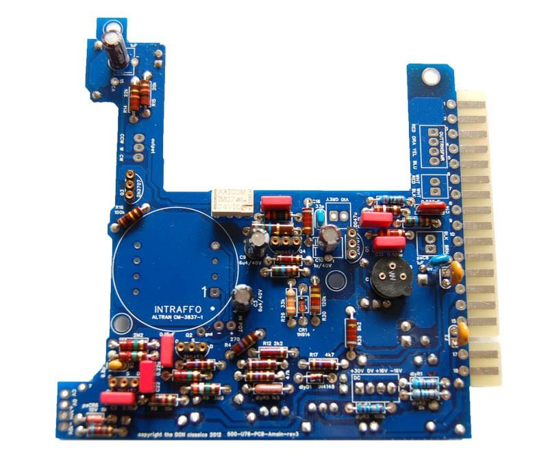
6 Control Amp PCB (CA PCB)
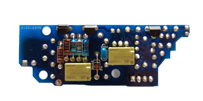
7 PS16Vto30V PCB
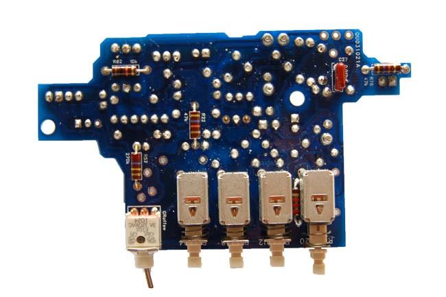
8 Meter PCB

 Then solder from")


9 PCB pins and sockets assembly: To solder the CA PCB sockets: Insert the 4 PCB sockets as shown. Hold the sockets in place from the top of the PCB (blue-tack or tape is good for this) Then solder from the bottom of the PCB. To solder the meter PCB pins: Insert the 4 PCB pins into the already soldered CA PCB sockets as shown. Place the meter PCB on the pins as shown and solder from the top. Remove and continue stuffing the rest of the components.


10 2. Wire pots Solder the output pot as follows: Solder the attack pot as follows:


11 Solder the release pot as follows: Solder the input pot as follows:


12 3. Solder transformers and meter Solder the C lining up the dot. Solder the 5002 wires straight to the board. Keep wires fairly tight so they won't hang outside the metalwork. Follow colour coding. NOTE: Due to an incorrect updated PCB silkscreen, if using rev3 main PCB then swap the red and blue wires on the PCB OR your unit will flip polarity. (It doesn't affect sound and will only be a problem if using parallel compression etc. You can rectify by flipping polarity in the DAW or by using a polarity reverse cable apologies for any inconvenience. Luckily as they're close to the edge of the PCB, you can desolder and rectify without removing PCB) All other PCB revisions are correct. Revision4 main PCB shown above. If using revision 3.. Swap the red and blue wires. Solder the meter in.


13 4. Place PCBs in metalwork Cut off the 2 extra gold fingers on main PCB if not using 51X GDIY lunchbox. Leave main PCB as it is if using 51X GDIY lunchbox. Insert PCBs into the metal work. You can use resistor legs to join the main PCB to the two molexs on the CA PCB. CA is connected to the right hole as shown. (marked 15 on PCB shown above)

 Next we will attach")
14 Line up the meter PCB so that the 4 legs are above the respective PCB sockets on the CA PCB. The trim pot screw should line up to the front panel. (as shown in the picture of the finished unit below) Next we will attach the PS16Vto30V PCB. Fasten the 3 standoffs to the PS16Vto30V PCB as shown.


15 Screw it into the metal work as shown and then tighten the green molex screws. Screw meter into metal work using 4 long countersunk screws and 4 small nuts.
 The 2N3053 (Q6) needs the heatsink provided. Insert op-amp into its socket on the meter PCB.")
16 5. Insert the transistors & op-amp * Make sure to check transistor orientation * Leave out Q1 and Q11 FETs for now. Insert all other FETs/transistors into the sockets. The CA PCB is all 2N3707. (Can also use 2N3708) The 2N3053 (Q6) needs the heatsink provided. Insert op-amp into its socket on the meter PCB. * Make sure to check op-amp orientation the dot should be closest to front panel *
17

 Don't insert the 2 FETs in case there is any problem on turn on. Turn the unit on. You should notice a little squeal from the start up circuit turning on.")
18 6. Initial test For initial tests, it may be worthwhile to build or buy a little jig to test units without having to root around in a lunchbox. eg. An EDAC attached to long wires attached to a PCB with the 15/18 gold fingers to insert to the lunchbox. (One source of card edge connectors and edge adapters is Jeff's excellent store classicapi) Before turn on - Make sure there is no shorts between the power rails. (pin 12, 13, 14) Don't insert the 2 FETs in case there is any problem on turn on. Turn the unit on. You should notice a little squeal from the start up circuit turning on. This is normal and will stop after a couple of seconds. Once the unit is on, measure to make sure you are reading +30V and -10V. You can check on the CA PCB molex. Run some audio through the unit with GR off and check that it sounds good and the gain controls work correctly. You should get about 50dB gain with pots up full. Make sure there is no buzz or hum from the unit. Turn off and move to the next step.
 If you have bought matched FETs then just insert them and move to step 8... To match FETs, you need to build a simple jig... There are many ways to match FETs.")
19 7. Match & insert FETs The reason we match FETs (Q1 and Q11) in a unit is so the meter will track properly. (So it is non critical to the sound, but necessary if you plan to use the meter!) If you have bought matched FETs then just insert them and move to step 8... To match FETs, you need to build a simple jig... There are many ways to match FETs... such as on the great site: AXT systems If you are unsure of the one above and want a very basic circuit, a circuit proposed by PRR of groupdiy.com is a very easy circuit to match FETs: Use a socket for the FET. TP = test point (negative probe on ground, positive probe on TP ) Measure the voltage with the switch open, then again with it closed. Write down the voltages. When you find two FETs with similar results, you've found a match. Easy!
20 8. Test and calibrate Once you have inserted your FETs, you are ready to set up and calibrate. Allow the unit to warm up for 10mins before adjusting. TIP: To monitor levels, you can use your DAW meters, or a VU meter plug-in is handy. For example, ProTools Bomb Factory VU meter at -18dB setting makes a perfect VU meter for our purposes. Q bias setup: Most important set up for the compressor to function right. Set up pots as follows: Input: Output: Attack: Release: GR switch: Ratio: Q-Bias (2k trimpot, CA PCB) Fully CCW Fully CW Fully CCW Fully CW OUT 20:1 Fully CCW From your DAW, insert a 1kHz -18dBFS tone (0dBu, 0.775V). Turn up the input pot until in your DAW you read -17dBFS (+1dBu, 0.869V). You can do this using either the DAW meters or a VU meter plug-in. What we now need to do is turn the Q-bias pot CW until we read the output as dropping 1dB back to -18dBFS tone (0dBu, 0.775V). Once achieved, the Q-bias is set.
21 Gain Reduction Meter Tracking To ensure the meter performs correctly. You need to repeat this a few times, due to the interaction of the adjustments. Set up pots as follows: Input: Output: Attack: Release: GR switch: Ratio: Tracking (100k trimpot, meter PCB) Mid rotation Fully CCW Fully CCW Fully CW OUT 20:1 ¼ from fully CCW With no signal applied, adjust Zero pot (2k pot, meter PCB accessible through front panel) until the meter reads 0. From your DAW, insert a -18dBFS tone (0dBu, 0.775V). 1. Adjust output pot until in your DAW you read -18dBFS tone (0dBu, 0.775V). 2. Now turn on GR switch. 3. Observe what level drop is in your DAW. We're looking for a 10dB drop. If it's less, turn up the input a little and repeat the last 3 steps. If it's more, turn down the input a little and repeat the 3 steps. When you have your 10dB drop, don't touch the input/output pots. We now need to make the meter read a -10dB drop... With GR on, turn the tracking (100k trim pot) CW until the meter reads -10dB. Turn GR off, adjust the zero (2k trim pot on front panel) until the meter reads 0dB. Due to the interaction of these two controls you'll need to repeat these 2 steps until both are correct. Meter zero adjust: Allow the unit to warm up for 10mins before adjusting. Every now and again the meter may need adjusting through the front panel. With GR off, adjust until the meter reads 0dB.
22 9. Attach front panel and knobs Attach front panel. Screw pots to front panel. Break off pot tab and use lock washer on the inside of the L-bracket. Place the knobs on the pot shafts. To have knobs a little closer to the front panel, mark how much you need to cut off the pot shafts. Either carefully using a dremel, cut off the excess length of the shaft.. or remove front panel, and then cut off excess pot shaft lengths. Once this is done, put the front panel on again, screw pots in, screw knobs on and you're finished!
23 Stereo operation For stereo operation: Match 4 FETs together (for Q1 & Q11 on each unit). Then just connect the 6th edge finger to the hole marked 7 near the CA PCB 4 hole molex.
Starving Student II. Starving Student II. SS2 guide. Written By: 6L guides.diyaudio.com/ Page 1 of 24
 SS2 guide Written By: 6L6 2019 guides.diyaudio.com/ Page 1 of 24 INTRODUCTION This is a build guide for the hybrid headphone/pre-amplifier. You can buy a kit at the SSII product listing on the diyaudio
TS500 Assembly guide. Soldering. TS500 Assembly guide Main PCB 1. Diodes. Document revision 1.2 Last modification : 17/12/16
 TS500 Assembly guide Safety warning The kits are main powered and use potentially lethal voltages. Under no circumstance should someone undertake the realisation of a kit unless he has full knowledge about
LA502 Assembly guide Main PCB Resistors - (2)
") LA502 Assembly guide Safety warning The kits are main powered and use potentially lethal voltages. Under no circumstance should someone undertake the realisation of a kit unless he has full knowledge about
LA502 Assembly guide Safety warning The kits are main powered and use potentially lethal voltages. Under no circumstance should someone undertake the realisation of a kit unless he has full knowledge about
Pingable Envelope Generator
 Pingable Envelope Generator Kit Builder's Guide for PCB v1.0.3 4mspedals.com PEG This guide is for building a Pingable Envelope Generator (PEG), which is an intermediate-level kit. You should be confident
MP573 Assembly guide. Soldering. MP573 Assembly guide PCB split PCB split. Document revision 2.2 Last modification : 22/08/17
 MP573 Assembly guide Safety warning The kits are main powered and use potentially lethal voltages. Under no circumstance should someone undertake the realisation of a kit unless he has full knowledge about
Assembly Instructions for the FRB FET FM 70 Watt Amp
 Assembly Instructions for the FRB FET FM 70 Watt Amp 1.) Orient the circuit board with the diagram 2.) Use a narrow chisel tip 25-30 watt soldering iron for assembly 3.) All the small parts are taped onto
Variable Gm Calibration Procedure
 Variable Gm Calibration Procedure REV. 3 Sept. 16, 2018. Warm-up Power on the unit and let it warm for about 20-30 minutes, so that all circuitries stabilize. A.C. Check With a DMM (Digital Multi Meter)
ALM473 DUAL MONO \ STEREO AUDIO LEVEL MASTER OPERATION MANUAL IB
 ALM473 DUAL MONO \ STEREO AUDIO LEVEL MASTER OPERATION MANUAL IB6408-01 TABLE OF CONTENTS GENERAL DESCRIPTION 2 INSTALLATION 2,3,4 CONNECTION AND SETUP 4,5,6,7 FUNCTIONAL DESCRIPTION 8,9 MAINTENANCE 9
Jour de FET Mounting instructions.
 Jour de FET Mounting instructions. Summary Important notice. What's in the kit? What you'll need. Soldering on the pcb. Wiring the pedal. Test the board. Debugging chapter. Hacks!!! 3 4 4 3 5 6 Copyright
Standard Kit #1 (5-way switch)
") Standard Kit #1 (5-way switch) Please Read All Instructions Before Beginning. Tools you will need: Soldering Iron (35 watt preferably) Solder Wet Sponge Wire Clippers 3/8 Drill Bit 1/4 Drill Bit Variable
Standard Kit #1 (5-way switch) Please Read All Instructions Before Beginning. Tools you will need: Soldering Iron (35 watt preferably) Solder Wet Sponge Wire Clippers 3/8 Drill Bit 1/4 Drill Bit Variable
Assembling the Heated bed
 firepickdelta Assembling the Heated bed Instructions for building the heated bed Written By: Neil Jansen 2017 firepickdelta.dozuki.com Page 1 of 15 Step 1 Exploded View Reference Use the full-size PDF
SDR Cube Transceiver Online Assembly Guide
 SDR Cube Transceiver Online Assembly Guide Detailed construction notes for building and testing each of the SDR Cube kit modules Home Bill of Materials I/O Board Controls Board DSP Board Softrock SR-Base
4ms SCM Breakout. Kit Builder's Guide for PCB v2.1 4mspedals.com
 4ms SCM Breakout Kit Builder's Guide for PCB v2.1 4mspedals.com Shuffling Clock Multiplier Breakout This guide is for building a Shuffling Clock Multiplier Breakout module (SCMBO) version 2.1 from the
SUPER-ENHANCED POLIVOKS VCA DIY KIT ASSEMBLY INSTRUCTIONS
 SUPER-ENHANCED POLIVOKS VCA DIY KIT ASSEMBLY INSTRUCTIONS IF YOU ARE READING THIS, MOST PROBABLY YOU ARE ABOUT TO BUILD ERICA SYNTHS SUPER-ENHANCED POLIVOKS VCA. The Polivoks VCA has distinctive architecture
Guitarpedalkits.com Overdrive Pedal Build Instructions
 Page 1 Guitarpedalkits.com Overdrive Pedal Build Instructions Follow the instructions in this guide to build your very own DIY overdrive pedal from GuitarPedalKits.com. If you re a first time builder,
Standard Kit #1 (3-way switch)
") Standard Kit #1 (3-way switch) Please Read All Instructions Before Beginning. Tools you will need: Soldering Iron (35 watt preferably) Solder Wet Sponge Wire Clippers 3/8 Drill Bit 1/4 Drill Bit Variable
Standard Kit #1 (3-way switch) Please Read All Instructions Before Beginning. Tools you will need: Soldering Iron (35 watt preferably) Solder Wet Sponge Wire Clippers 3/8 Drill Bit 1/4 Drill Bit Variable
IR add-on module circuit board assembly - Jeffrey La Favre January 27, 2015
 IR add-on module circuit board assembly - Jeffrey La Favre January 27, 2015 1 2 For the main circuits of the line following robot you soldered electronic components on a printed circuit board (PCB). The
Geiger Counter Kit Assembly Instructions ( )
") Geiger Counter Kit Assembly Instructions (2012-05-11) To build this kit, you should know how to solder. And it will be much easier if you have made other kits before. But even if this is your first kit,
Geiger Counter Kit Assembly Instructions (2012-05-11) To build this kit, you should know how to solder. And it will be much easier if you have made other kits before. But even if this is your first kit,
The Walford Electronics Ford Receiver Kit Project Construction Manual
 The Walford Electronics Ford Receiver Kit Project Construction Manual Walford Electronics Ford Receiver construction manual V1.5 Page 1 of 22 Introduction The Ford receiver has four stages: The first stage
INSTRUCTIONS FOR ASSEMBLY AND OPERATION
 diytube stereo 0 driver board INSTRUCTIONS FOR ASSEMBLY AND OPERATION Price $0.00 Important Note: The phase is swapped on the diytube ST0 from the orginal design. Be sure to hook up the drive lines (at
STEP 0 Prepare the Materials.
 How to Build a Germanium Fuzz Guitar Effect. This document will guide you to build and test your Germanium Fuzz guitar pedal. With all the materials on hand, it takes around 2-4 hours to build it. Try
THE AGGRESSOR (K-995)
") THE AGGRESSOR (K-99) TONE VOLUME DISTORTION MID-SHIFT SWITCH LED The Aggressor Distortion Pedal Modkitsdiy.com 9 VDC CENTER (-) ADAPTER TO AMP IN FROM GUITAR OUT Unplug when not in use to save battery
THE AGGRESSOR (K-99) TONE VOLUME DISTORTION MID-SHIFT SWITCH LED The Aggressor Distortion Pedal Modkitsdiy.com 9 VDC CENTER (-) ADAPTER TO AMP IN FROM GUITAR OUT Unplug when not in use to save battery
HT-1A Dual Band CW QRP Transceiver. Kit Building Instructions
 HT-A Dual Band CW QRP Transceiver Kit Building Instructions Rev B, July 8, 08 Designed by BD4RG Exclusively distributed by CRKITS.COM and its worldwide distributors Join the group http://groups.io/g/crkits
Assembly Instructions for the 1.5 Watt Amplifier Kit
 Assembly Instructions for the 1.5 Watt Amplifier Kit 1.) All of the small parts are attached to a sheet of paper indicating both their value and id. 2.) Leave the parts affixed to the paper until you are
Telecaster Wiring Kits Please Read All Instructions Before Beginning. Tools you will need: Soldering tips: Removing Current Wiring: Step 1. Step 2.
 Telecaster Wiring Kits Please Read All Instructions Before Beginning. Tools you will need: Soldering Iron (35 watt preferably) Solder Wet Sponge Wire Clippers Wire Strippers 3/8 Drill Bit 5/32 Drill Bit
Penrose Quantizer Assembly Guide
 Penrose Quantizer Assembly Guide Schematic and BOM The schematic can be found here: www.sonic-potions.com/public/penrosequantizerschematic.pdf The BOM is available at google docs: Link to BOM Prepare the
Music Thing Modular SimpleEQ Construction Guide (1206 version)
") Music Thing Modular SimpleEQ Construction Guide (1206 version) Page 1 Useful Links The latest version of this doc and BOM can always be found at http://thonk.co.uk/documents/eq/ A build thread on the Muffwiggler
Music Thing Modular SimpleEQ Construction Guide (1206 version) Page 1 Useful Links The latest version of this doc and BOM can always be found at http://thonk.co.uk/documents/eq/ A build thread on the Muffwiggler
Bill of Materials: General Purpose Alarm, Pulsed PART NO
 General Purpose Alarm, Pulsed PART NO. 2190207 I hate alarms that sound continuously - unless they are smoke alarms. Smoke alarms should be annoying, but others should not. I wanted an alarm for a function
Glue Fuzz Mounting instructions.
 Glue Fuzz Mounting instructions. Index Important notice. 2 What's in the kit? 3 What you'll need. 4 Soldering on the pcb. 4 Wiring the pedal. 11 Test the board. 12 Debugging chapter. 13 Copyright Zorg
MICROGRANNY v2.1 - Assembly Guide
 last update: 9. 5. 2017 MICROGRANNY v2.1 - Assembly Guide bastl-instruments.com INTRODUCTION Welcome to the assembly guide for the MicroGranny kit. MicroGranny is a monophonic granular sampler by Bastl
The ability to make basic voltage and resistance measurements using a digital multimeter
 Congratulations on your purchase of a new OneShot chassis! The PC01 OneShot combines a rugged enclosure, power supply, and discrete instrument DI in a compact 1/4U package. A few minutes of assembly are
SoftRock v6.0 Builder s Notes. May 22, 2006
 SoftRock v6.0 Builder s Notes May 22, 2006 Be sure to use a grounded tip soldering iron in building the v6.0 SoftRock circuit board. The soldering iron needs to have a small tip, (0.05-0.1 inch diameter),
D. Gillespie Designs. SCA-35 Capacitor Board. Installation Manual. D. Gillespie Designs with EFB TM
 D. Gillespie Designs SCA-5 Capacitor Board with EFB TM Installation Manual D. Gillespie Designs www.tronola.com Thank you for choosing our SCA-5 Capacitor Board with *EFB. We feel it is the single most
Brief Installation Procedure: 1. Check the Parts 2. assembly each channel in brief and make sure the assembly is correct. 3. assembly the chassis in
 Brief Installation Procedure: 1. Check the Parts 2. assembly each channel in brief and make sure the assembly is correct. 3. assembly the chassis in brief, and make sure no small parts missed. 4. fixed
The Useless Machine. Parts Only - Build Guide v0001
 TM The Useless Machine Parts Only - Build Guide v0001 For the best outcome, follow each step in order. We recommend reading this guide entirely before you get started. Tools required: One phillips screwdriver,
Building a Bitx20 Version 3
 Building a Bitx20 Version 3 The board can be broken into sections and then built and tested one section at a time. This will make troubleshooting easier as any problems will be confined to one small section.
R*S Stereo Mixer V1.2
 R*S Stereo Mixer V1.2 The Random*Source Equal Power Stereo-Mixer is a voltage controlled stereo mixer / panner / VCA based on 4 high-end THAT2180 blackmer VCAs, designed to emulate the behavior of Serge
nonlinearcircuits QUO/LPF build notes version 2 11 April 2014
 nonlinearcircuits QUO/LPF build notes version 2 11 April 2014 This circuit is based on the 4 pole LPF in Electronotes 41, tho has been subject to a number of tweaks and prods to bring it to where it is
PM124 Installation Instructions. See important note about revisions of this board on the last page.
 Marchand Electronics Inc. PO Box 473, Webster, NY 14580 Tel:(716) 872-0980 Fax:(716) 872-1960 info@marchandelec.com http://www.marchandelec.com (c)1997 Marchand Electronics Inc. PM124 Installation Instructions
INSPIRE VLF-3 Rev #1C Receiver Kit ASSEMBLY INSTRUCTIONS
 INSPIRE VLF-3 Rev #1C Receiver Kit ASSEMBLY INSTRUCTIONS The following assembly instructions should be followed carefully. The INSPIRE VLF-3 receiver kit is NOT a simple electronic assembly. If you follow
NEW DESIGN***DEM Part Number FRS***NEW DESIGN Low power 144 MHz Transverter for the Flex Radio System SDR-1000 Operating Specifications:
 NEW DESIGN***DEM Part Number 144-28FRS***NEW DESIGN Low power 144 MHz Transverter for the Flex Radio System SDR-1000 Operating Specifications: Operating Voltage: 12.0-15.5 VDC, 13.8 nominal Current Drain:
CAPI LC53A 3-Band Equalizer Kit
 CAPI LC53A 3-Band Equalizer Kit All Discrete Vintage Style 500 Series Format Required Tools, assembly tips and pointers: These can be found in the VP2x Assembly Guide. All of the tips and pointers there
S-Pixie QRP Kit. Student Manual. Revision V 1-0
 S-Pixie QRP Kit Student Manual Revision V 1-0 Introduction The Pixie 2 is a small, versatile radio transceiver that is very popular with QRP (low power) amateur radio operators the world over. It reflects
Balanced Modulator. Model 9748 Assembly and Using Manual PAiA Corporation
 Balanced Modulator Model 9748 Assembly and Using Manual This second-generation 9700-series processing element for modular sound synthesizers is designed to provide great sound and excellent value. Audio
Instructions for Building the Pulsed Width Modulation Circuit. MC-12 (DC Motor Controller or PWM) From Electronic Light Inc. (revised kit 10/03/08)
 From Electronic Light Inc. (revised kit 10/03/08)") Instructions for Building the Pulsed Width Modulation Circuit MC-12 (DC Motor Controller or PWM) From Electronic Light Inc. (revised kit 10/03/08) Congratulations on your purchase of the MC-12 DC Motor
Instructions for Building the Pulsed Width Modulation Circuit MC-12 (DC Motor Controller or PWM) From Electronic Light Inc. (revised kit 10/03/08) Congratulations on your purchase of the MC-12 DC Motor
Line-Following Robot
 1 Line-Following Robot Printed Circuit Board Assembly Jeffrey La Favre October 5, 2014 After you have learned to solder, you are ready to start the assembly of your robot. The assembly will be divided
THE THUNDERDRIVE (K-950)
") THE THUNDERDRIVE (K-950) OUTPUT DISTORTION Unplug when not in use to save battery life. TO AMP IN The Thunderdrive Modkitsdiy.com FROM GUITAR OUT Use these instructions to learn: How to build an effects
THE THUNDERDRIVE (K-950) OUTPUT DISTORTION Unplug when not in use to save battery life. TO AMP IN The Thunderdrive Modkitsdiy.com FROM GUITAR OUT Use these instructions to learn: How to build an effects
Hendricks QRP Kits The Twofer Rev
 Hendricks QRP Kits The Twofer Rev 1 11-15-06 1. Description The Twofer is a classic QRP transmitter that s easy to assemble and operate. It uses a JFET VXO (variable crystal oscillator), driver stage and
Some KWM-2/2A Tricks. January By Georges, F6CER CCAE# 098. Some KWM-2/2A Tricks -
 Some KWM-2/2A Tricks January 2016 By Georges, F6CER CCAE# 098 Some KWM-2/2A Tricks Most of the KWM-2 transceivers that can be found in Europe belong to the first generation manufactured at the beginning
Aquaboy FX TYPE: Delay Based on the Boss DM madbeanpedals
 Aquaboy FX TYPE: Delay Based on the Boss DM-2 2016 madbeanpedals 2.3 W x 3.125 H 1.29.17 Correction see page 6. Note: the M pad by the Delay pot is for modulation control (see the AB_MOD documentation
Service Manual for XLE/XLT Series Laser Engravers
 Service Manual for XLE/XLT Series Laser Engravers Table of Contents Maintenance...1 Beam alignment...3 Auto focus alignment...8 Bridge alignment...10 Electronics panel replacement...11 X motor change...12
Value Location Qty Potentiometers C1M Distortion 1 A10k Volume 1. Footswitch 3PDT SW1 1. Jacks 1/4 Mono 2 DC Power 1
 Distortion BUILD INSTRUCTIONS Thank you for your purchase of our Distortion+ kit! We have completely redesigned our entire line of kits to be the most user friendly, while still maintaining their same
SIMPLE DIRECT DRIVE DESULPHATOR/ DESULFATOR KIT INSTRUCTIONS
 SIMPLE DIRECT DRIVE DESULPHATOR/ DESULFATOR KIT INSTRUCTIONS Parts List C1 470uF/ 25V 1off C2 C5 0.1uF/ 50V 4off C6 C9 0.01uF/ 50V 4off D1 12V/ 1.3W zener 1off Q1 2N2907 1off Q2 Q4 IRFB3307 3off R1 510R/
BrewsBySmith.com STC DIY Kit
 BrewsBySmith.com STC-1000 + DIY Kit Contact Information: Greg Smith www.brewsbysmith.com greg@boostbysmith.com I. Hardware Included: STC-1000 flashed with latest software (v1.06 currently) (if purchased)
EZ1290 Assembly Guide
 EZ190 Assembly Guide Capacitors This picture shows the different types of capacitors used and how they are symbolized and mounted on the PCB. Don t mess this up or bad things will happen!!! Electrolytic
THE TRILL TREMOLO (K-960)
") THE TRILL TREMOLO (K-60) DEPTH SPEED The Trill Tremolo Modkitsdiy.com Unplug when not in use to save battery life. TO AMP IN FROM GUITAR OUT Use these instructions to learn: How to build an effects pedal
THE TRILL TREMOLO (K-60) DEPTH SPEED The Trill Tremolo Modkitsdiy.com Unplug when not in use to save battery life. TO AMP IN FROM GUITAR OUT Use these instructions to learn: How to build an effects pedal
Read This Page First
 Read This Page First If you are reading this you know the manuals are always available at QRPKITS.com. This is version 8.0 of the manual dated 4/27/2016. There is no need to print out the whole assembly
ELECRAFT KXPD1 PLUG-IN KEYER PADDLE
 Introduction ELECRAFT KXPD1 PLUG-IN KEYER PADDLE Assembly and Operating Instructions Revision B, July 27, 2011. Copyright 2011, Elecraft; All Rights Reserved The KXPD1 is a unique plug-in keyer paddle
How to repair a broken potentiometer or pot
 You pulled off the tone knob and it pulled out the stem piece with it; now it won't go back in. Watch this guide to see how to repair it. Written By: Adonis Urick Page 1 of 11 INTRODUCTION This shows how
Find a place where you can work through completion, without disturbing your
 Scan by Manual Manor ARIES SYSTEM 300 MUSIC SYNTHESIZER Page I of 4 MODULE AR-334 SEQUENCER ASSEMBLY INSTRUCTIONS It is recommended that you do the following before you proceed: Find a place where you
ABC V1.0 ASSEMBLY IMPORTANT!
 ABC V1.0 ASSEMBLY Before starting this kit, prepare the following tools: Soldering iron (15-20W will do), flush cutters, no.2 hex screwdriver or allen key and phillips screwdriver. Also briefly go through
Total solder points: 79 Difficulty level: beginner advanced GUITAR PREAMPLIFIER WITH HEADPHONE OUTPUT K4102 ILLUSTRATED ASSEMBLY MANUAL
 Total solder points: 79 Difficulty level: beginner 1 2 3 4 5 advanced GUITAR PREAMPLIFIER WITH HEADPHONE OUTPUT K4102 Practice the guitar without disturbing others. ILLUSTRATED ASSEMBLY MANUAL H4102IP-1
SOUND ANCHOR ASSEMBLY INSTRUCTIONS FOR MOTORIZED STUDIO MONITOR STAND WITH FIXED START HEIGHT
 SOUND ANCHOR ASSEMBLY INSTRUCTIONS FOR MOTORIZED STUDIO MONITOR STAND WITH FIXED START HEIGHT Thank you for purchasing Sound Anchor Motorized Monitor Stands. These stands were specifically developed with
Lighthouse Beginner s soldering kit
 Lighthouse Beginner s soldering kit Kit contains: 1 x 220 ohm resistor (Red, Red, Black) 1 x 82k ohm resistor (Grey, Red, Orange) 2 x 220k ohm resistors (Red, Red, Yellow) 2 x Diodes 1 x Power switch 1
Manual Version July 2007
 Manual Version 1.2 - July 2007 Page 1 Table of Contents Section1: M3 Phono Board Build...3 Phono Board Parts List...3 Preparation...4 Fitting the Valve Bases...6 Installing the Resistors...7 Starting the
THE RING RESONATOR (K-975)
") THE RING RESONATOR (K-975) OUTPUT BOOST The Ring Resonator An Octave Up Fuzz Modkitsdiy.com 9 VDC CENTER (-) ADAPTER TO AMP IN FROM GUITAR OUT Unplug when not in use to save battery life. Use these instructions
THE RING RESONATOR (K-975) OUTPUT BOOST The Ring Resonator An Octave Up Fuzz Modkitsdiy.com 9 VDC CENTER (-) ADAPTER TO AMP IN FROM GUITAR OUT Unplug when not in use to save battery life. Use these instructions
DeluxeArcade. JAMMA Fingerboard. Introduction. Features. Version 1.1, November 2014 Martin-Jones Technology Ltd
 DeluxeArcade JAMMA Fingerboard Version., November 204 Martin-Jones Technology Ltd http://www.martin-jones.com/ Introduction The Deluxe Arcade JAMMA Fingerboard is designed to make adapting non-jamma arcade
Envelope Follower. Model 9753 Assembly and Using Manual PAiA Corporation
 Envelope Follower Model 9753 Assembly and Using Manual This second-generation 9700-series processing element for modular sound synthesizers is designed to provide great sound and excellent value. The -11,
Value Location Qty Transistors 2N5485 Q1, Q2, 4 Q3, Q4 2N5087 Q5 1. Trim Pots 250k VTRIM 1. Potentiometers C500k Speed 1. Toggle Switch On/On Vibe 1
 P-90 BUILD INSTRUCTIONS Thank you for your purchase of our P-90 kit! We have completely redesigned our entire line of kits to be the most user friendly, while still maintaining their same great sound!
ABM International, Inc.
 ABM International, Inc. Lightning Stitch required 1 1.0: Parts List head and motor assembly (Qty. 1) Reel stand (Qty. 1) Needle bar frame clamp (Qty. 1) Motor drive (Qty. 1) 2 Cable harness with bracket
The Tellun Corporation. TLN-442 Voltage Controlled Lowpass Filter. User Guide, Rev Scott Juskiw The Tellun Corporation
 The Tellun Corporation TLN-442 Voltage Controlled Lowpass Filter User Guide, Rev. 1.1 Scott Juskiw The Tellun Corporation scott@tellun.com TLN-442 User Guide Revision 1.1 March 15, 2003 Introduction The
Explorer Wiring Kit (assembled)
") Explorer Wiring Kit (assembled) For Vintage, Firestorm & Standard Series Please Read All Instructions Before Beginning. Tools you will need: Soldering Iron (35 watt preferably) Solder Wet Sponge Wire Clippers
Explorer Wiring Kit (assembled) For Vintage, Firestorm & Standard Series Please Read All Instructions Before Beginning. Tools you will need: Soldering Iron (35 watt preferably) Solder Wet Sponge Wire Clippers
3DR ArduCopter Quad-C
 3DR ArduCopter Quad-C 3DR ArduCopter Quad-C Thank you for purchasing a 3DR ArduCopter Quad kit. The 3DR ArduCopter Quad is a stable and supported multi-rotor frame in the ongoing development of the ArduCopter
Bill of Materials: PWM Stepper Motor Driver PART NO
 PWM Stepper Motor Driver PART NO. 2183816 Control a stepper motor using this circuit and a servo PWM signal from an R/C controller, arduino, or microcontroller. Onboard circuitry limits winding current,
Step by Step Building PJ meter ARDF Receiver Kit. CRKITS.COM August 5, 2013
 Step by Step Building PJ-80 80-meter ARDF Receiver Kit CRKITS.COM August 5, 2013 What is ARDF? ARDF is the abbreviation of Amateur Radio Direction Finding, or so called Fox Hunting. If you are looking
LITTLE NERD v1.1 Assembly Guide
 last update: 9. 3. 2016 LITTLE NERD v1.1 Assembly Guide bastl instruments.com INTRODUCTION This guide is for building Little Nerd module from Bastl Instruments. It is good to have basic soldering skills
HAMTRONICS R100 VHF FM RECEIVER: ASSEMBLY, INSTALLATION, OPERATION, & MAINTENANCE
 HAMTRONICS R100 VHF FM RECEIVER: ASSEMBLY, INSTALLATION, OPERATION, & MAINTENANCE Note about page numbers. In order to accommodate various bands, this manual has extra pages you may not receive for your
HAMTRONICS TB901 FM EXCITER INSTALLATION, OPERATION, & MAINTENANCE
 HAMTRONICS TB901 FM EXCITER INSTALLATION, OPERATION, & MAINTENANCE GENERAL INFORMATION. The TB901 is a single-channel low power fm transmitter (exciter) designed to provide 300-600 milliwatts continuous
400A 40113V, 401A 40120V, & 401AL 40120VL ALUMINUM VERTICAL 4000 LB LIFT INCLUDES SCREW LEG ASSEMBLY INSTRUCTIONS
 12/11/07 PAGE 1 OF 12 400A 40113V, 401A 40120V, & 401AL 40120VL ALUMINUM VERTICAL 4000 LB LIFT INCLUDES SCREW LEG ASSEMBLY INSTRUCTIONS Thank you for purchasing our product! *Please read these instructions
555 Morse Code Practice Oscillator Kit (draft 1.1)
") This kit was designed to be assembled in about 30 minutes and accomplish the following learning goals: 1. Learn to associate schematic symbols with actual electronic components; 2. Provide a little experience
This kit was designed to be assembled in about 30 minutes and accomplish the following learning goals: 1. Learn to associate schematic symbols with actual electronic components; 2. Provide a little experience
DIY Function Generator XR2206
 DIY Function Generator XR2206 20Hz 100KHz http://radiohobbystore.com Components List: Resistors: R1, R2 1% Metal Film 5K1 R4 1% Metal Film 10K R5 1% Metal Film 3K R10 5% Carbon Film 10R R3, R9 Potentiometer
GCI BRUTALIST JR. BUILD GUIDE
 GCI BRUTALIST JR. BUILD GUIDE The Brutalist Jr. is the DIY little brother to the GCI Brutalist, a high powered distortion pedal loosely based on the Providence Stampede SDT-1. It runs on 9v DC power or
CLASS A DUAL TRANSFORMER COMPRESSOR OWNER S MANUAL
 LIMINATOR CLASS A DUAL TRANSFORMER COMPRESSOR OWNER S MANUAL TABLE OF CONTENTS SECTION PAGE INTRODUCTION 2 INSTALLATION 3 FRONT PANEL CONTROLS 4 OPERATION 5 SPECIFICATIONS 7 WARRANTY AND REGISTRATION 8-1
Assembly Manual V1R2B-Rev1.0D
 Assembly Manual V1R2B-Rev1.0D for 4 State QRP MagicBox - Solid State Transmit/Receive System Designed by: Jim Kortge, K8IQY Copyright 2009-2012 - All rights reserved This system is the result of some brainstorming
Icom IC-781 (IC 781 IC781) filter modification
 filter modification") Icom IC-781 (IC 781 IC781) filter modification The stock FL-96 (455 khz SSB: 2,8 khz wide @ -6 db) can be replaced with an FL-44A (2,4 khz wide @ -6 db) to improve adjacent-channel selectivity and sharpen
Icom IC-781 (IC 781 IC781) filter modification The stock FL-96 (455 khz SSB: 2,8 khz wide @ -6 db) can be replaced with an FL-44A (2,4 khz wide @ -6 db) to improve adjacent-channel selectivity and sharpen
TLN-428 Voltage Controlled State Variable Filter
 The Tellun Corporation TLN-428 Voltage Controlled State Variable Filter User Guide, Rev. 1.1 Scott Juskiw The Tellun Corporation scott@tellun.com TLN-428 User Guide Revision 1.1 March 16, 2003 Introduction
Instructions for Building the Pulsed Width Modulation Circuit. MC-12 (DC Motor Controller or PWM) From Electronic Light Inc. (revised kit 5/08)
 From Electronic Light Inc. (revised kit 5/08)") Instructions for Building the Pulsed Width Modulation Circuit MC-12 (DC Motor Controller or PWM) From Electronic Light Inc. (revised kit 5/08) Using this circuit for a pulsed DC current to your cell. Do
Instructions for Building the Pulsed Width Modulation Circuit MC-12 (DC Motor Controller or PWM) From Electronic Light Inc. (revised kit 5/08) Using this circuit for a pulsed DC current to your cell. Do
MAINTENANCE MANUAL AUDIO MATRIX BOARD P29/
 MAINTENANCE MANUAL AUDIO MATRIX BOARD P29/5000056000 TABLE OF CONTENTS Page DESCRIPTION................................................ Front Cover CIRCUIT ANALYSIS.............................................
PAT-4 POWER SUPPLY ASSEMBLY MANUAL Rev B Version
 PAT-4 POWER SUPPLY ASSEMBLY MANUAL Rev B Version 2013 AkitikA, LLC All rights reserved Revision Bp01 November 3, 2013 Page 1 of 16 Table of Contents Table of Contents... 2 Table of Figures... 2 Section
Assembly and Installation Instructions for White Oak Audio Design TM-1001 LED board
 Thank you for purchasing White Oak Audio Design s TM-1001 Upgrade LED Light Board. White Oak Audio Design products are meticulously engineered and tested to ensure a direct drop in fit with your tuner.
PULL-THRU USER S MANUAL
 PULL-THRU USER S MANUAL G14x Part # 310 120 177 G20 Part # 310 120 188 G20x Part # 310 120 186 G40x Part # 310 120 163 TABLE OF CONTENTS SECTION 1 PCB DESIGN AND MOUNTING SECTION 2 MOUNTING ADAPTER TO
Dual Digital Build Manual
 Dual Digital Build Manual Introduction This document is meant to aid you in assembling your Dual Digital Oscillator (DDO from now on). Some instructions may be a bit basic for advanced builders but I hope
Construction Guide European Version
 Construction Guide European Version PCB This section describes how to build up the DRO-350 printed circuit board (PCB). The bare PCB is available for purchase on the order page. Static Protection Bare
Instructions for Building the Pulsed Width Modulation Circuit. MC-12 (DC Motor Controller or PWM) From Electronic Light Inc. (revised kit 8/08)
 From Electronic Light Inc. (revised kit 8/08)") Instructions for Building the Pulsed Width Modulation Circuit MC-12 (DC Motor Controller or PWM) From Electronic Light Inc. (revised kit 8/08) Using this circuit for a pulsed DC current to your cell. Do
Instructions for Building the Pulsed Width Modulation Circuit MC-12 (DC Motor Controller or PWM) From Electronic Light Inc. (revised kit 8/08) Using this circuit for a pulsed DC current to your cell. Do
Tin Lizzie 18 Assembly Instructions
 Tin Lizzie 18 Assembly Instructions Revision: 07/29/16 Table of Contents Aides 3 Before You Begin 5 Aides 5 Tools 6 Perfect Stitch Parts 2 12 Modify the Machine 12 Prepare Drill Templates 12 Front Display
Chameleon Labs Model 7602
 Chameleon Labs Model 7602 Microphone Preamplifier and Equalizer Owner s Manual 704 228 th Avenue NE, # 826 Sammamish, WA 98074 206-264-7602 www.chameleonlabs.com Revision B Dec, 2005 1 Your Model 7602
Multiwave. Guitar Synthesizer. Build Document last updated november 2018 Version
 Multiwave Guitar Synthesizer Build Document last updated november 2018 Version 1.0 2018 The Multiwave is a guitar controlled oscillator with 3 different waveshapes: saw, triangle and square. Combined,
Congratulations on your purchase of the SparkFun Arduino ProtoShield Kit!
 Congratulations on your purchase of the SparkFun Arduino ProtoShield Kit! Well, now what? The focus of this guide is to aid you in turning that box of parts in front of you into a fully functional prototyping
UK-electronic 2008/13
 UK-electronic 2008/13 Assembly manual for Kit BOR Clone Rev. 1.22 (2N7000) Ver. 2014 Page 3...Bill of material Page 4..5...soldering the pcb Page 5...pcb layout top Page 6...wiring diagram Page 7..8...enclosure,
Printrbot Simple (Model 1403) Rev F Printrboard
 Rev F Printrboard") Printrbot Simple (Model 1403) Rev F Printrboard Printrbot Simple is currently shipping with the Rev F Printrboard. Check which rev Printrboard your Simple kit includes and use the corresponding instructions.
Printrbot Simple (Model 1403) Rev F Printrboard Printrbot Simple is currently shipping with the Rev F Printrboard. Check which rev Printrboard your Simple kit includes and use the corresponding instructions.