Brief Installation Procedure: 1. Check the Parts 2. assembly each channel in brief and make sure the assembly is correct. 3. assembly the chassis in
|
|
|
- Jerome Mills
- 6 years ago
- Views:
Transcription
1 Brief Installation Procedure: 1. Check the Parts 2. assembly each channel in brief and make sure the assembly is correct. 3. assembly the chassis in brief, and make sure no small parts missed. 4. fixed the Power rectifier board, bridge and the transformer on the chassis, don t tight up the transformer yet 5. connect the power to test power regulator+ transformer and the bridge in order to make sure connect correctly. (if you have oscillator, you can connect and see is it clean or not) 6. connect the power to the amplifier board to see is the power supply is correct or not. 7. re connect the power to tune the middle voltage(0v), adjust the bias 8. after tune the middle voltage and the bias, solder the stuff up, fix the amplifier board on the heatsink, 9. tighen up the screws and if you have oscillator, test with frequency generator) 10. connect the cables.

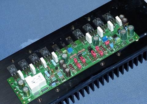
2 Installation The Heatsink on each side is actually 3 smaller heatsink connect together, and use 1 large long aluminum board as the base board to connect the amplifier PCB with the heatsink. All the holes are predrilled for the PCB and heatsink.

3 Afterward, we need to assemble the chassis, factory does not provide the installation manual, it is definitely a little bit hard for beginner. OK, let play with that Lego. Bottom and the rear board is the same board and bended into L-shape already. Front panel is using exclude techniques and brush afterward. 2 x L-Shape steel plate, used to assembly the front panel with the side board(heatsink).

4 I believe every guy can t wait to start assembly the sutff, I have used some cooling oil between heatsink and the base board. Need to screw not too powerful as the heatsink is pre drilled and then do the anodizing electrolyte.

5 As PCB is already semi-finish, there is not much to do. just do the quality assurance once more. I have disconnect the 10K5 resistor in order to adjust the 0 voltage.

6 In order to maximize the connect surface between the capacitor and the copper, I flip the pcb for soldering. And I also connect WIMA 0.1uf in parallel. (In the photos is the RIFA cap, it is sold out at the moment.)

7 And then place the stereo amp board, rectifier board,bridge and the transformer inside the chassis in order to see anything missed. The bridge and the rectifier holes are not predrilled! It need to drilled manually!

8 And then I placed most of the small item,like power on off button.

9 Now, I placed the amplifier board to the heat sink, there are many holes, I use the 4 holes at 4 corners of PCB to find out any holes fit. Luckily it is still easy to find, after that I placed the silicon sticker between the transistor and the heatsink. Don t screw too tight, the transistor may be enlarge a bit when it get hot.
10


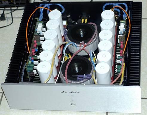
11 After that, I fixed the RCA connector and the IEC Socket, the IEC socket is you see in the photo is something I bought a few years ago, not included in the kit. Pictures of the transformer, it looks nice.

12 I have used 2 resistors in series to the amplifier board for testing, both of them are 5W1R, at first I set the bias current as 0.45A, and then I adj the bias currect to 1Ohm, voltage drop almost 0.55V then, Please make sure when you test 2 channel using the same resistors then 2 channel s board bias will almost the same. For my experience, the adjustment is a trial and error process. You cannot get it done 1 first round, you need to test in when it is cool, after that you may warm it up with music with dynamic range for 15 minutes and test it one more time. Middle voltage also need to tune, because the middle voltage will also change based on temperature, therefore, will I start the amp, I adj in brief, every times I adj the bias, and test the middle voltage also. Every time I tune, I tune into 1/3 to 1/2 and let it float slowing, Actually, if you do not know how to adj the bias and the middle voltage, you may not fine tune in this details. The factory pre-tuned the amp board before they sell it. My friend s M-9 also did not tune anything and run perfectly. After I tune the bias and the middle voltage, reconnect the DC Servo resistor. For the wiring cables, main power supply use 2mm OCC single core, speaker output use OCC multi core cables in parallel. But the single core is hard, I bend it with extreme careful. And also You may stick a Blue Tack between the rectifier capacitor with the board to fix it more firmly.

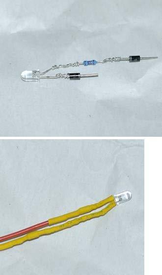
13 It is almost done, You may now connect the LED light, normally you need to connect a resistor with LED in series is enough. Because I am a little bit worry, therefore, I bought 2 more Diodes for safety. It the AC Power supply, before the fuse, I add 1 more negative temperature sensitive resistor, CL60. the we power on the amp, it is for the current flooding protection purpose.
14

15 Now I wired the LED signal cable. Because I am lazy, I connect to some where nearer. Luckily I have play the amp for 3 months, and It got no problem.

16 Here are the finish photos, actually the wires are not many. Here are the cables you may need. 1. RCA input to amplifier board 2. AC IEC to fuse, fuse to transformer. 3. Beidge to Power rectifier board 4. Power rectifier board to main Amplifier board 5. Main amplifier board to speaker out 6. LED to power supply on the left hand side may not be long enough, you may I a very short wire to lengthen it. 8.
17

18 Photos from another viewpoint, signal cables are a little bit too long, after I cover it up, then they will stick to the top board, I won t see it.
Warm Tube Clock. Before we start, please make sure that you have all required parts that come for the main board :
 Warm Tube Clock Assembly Instructions for the main board Introduction Congratulations on your purchase of OSH Nixie Tube Clock. In this document you will see all steps you need to follow in order to successfully
Starving Student II. Starving Student II. SS2 guide. Written By: 6L guides.diyaudio.com/ Page 1 of 24
 SS2 guide Written By: 6L6 2019 guides.diyaudio.com/ Page 1 of 24 INTRODUCTION This is a build guide for the hybrid headphone/pre-amplifier. You can buy a kit at the SSII product listing on the diyaudio
Assembly Instructions for the 1.5 Watt Amplifier Kit
 Assembly Instructions for the 1.5 Watt Amplifier Kit 1.) All of the small parts are attached to a sheet of paper indicating both their value and id. 2.) Leave the parts affixed to the paper until you are
Simple EL84 Basic layout. DIY Paradise 13 June 2003
 Simple EL84 Basic layout DIY Paradise 13 June 2003 EL84 doesn t sing without feedback. EL84 has no bass. These are comments I gleamed off the World Wide Web from various places. The truth is, if the circuit
Assembly Instructions for the FRB FET FM 70 Watt Amp
 Assembly Instructions for the FRB FET FM 70 Watt Amp 1.) Orient the circuit board with the diagram 2.) Use a narrow chisel tip 25-30 watt soldering iron for assembly 3.) All the small parts are taped onto
Introduction 1. Download socket (the cable plugs in here so that the GENIE microcontroller can talk to the computer)
") Introduction 1 Welcome to the magical world of GENIE! The project board is ideal when you want to add intelligence to other design or electronics projects. Simply wire up your inputs and outputs and away
Introduction 1 Welcome to the magical world of GENIE! The project board is ideal when you want to add intelligence to other design or electronics projects. Simply wire up your inputs and outputs and away
REPAIRING THE RM KL400 LINEAR AMPLIFIER.
 REPAIRING THE RM KL400 LINEAR AMPLIFIER. Les Carpenter G4CNH December 2012 Page 1 of 20 The following is a step by step guide to fixing your KL400 amplifier. Each part will be individually tested up to
Warm Tube Clock. Before we start, please make sure that you have all required parts that come for the IN-16 Nixie shield :
 Warm Tube Clock Assembly Instructions for the IN-16 Nixie shield Introduction Congratulations on your purchase of OSH Nixie Tube Clock. In this document you will see all steps you need to follow in order
EZ1290 Assembly Guide
 EZ190 Assembly Guide Capacitors This picture shows the different types of capacitors used and how they are symbolized and mounted on the PCB. Don t mess this up or bad things will happen!!! Electrolytic
How to build a Cracklebox. Red Wierenga Brooklyn College Center for Computer Music October 13, 2015
 How to build a Cracklebox Red Wierenga Brooklyn College Center for Computer Music October 13, 2015 What s a Cracklebox? What s a Cracklebox? The Cracklebox was developed by Michel Waisvisz and others at
the DON classics U76 (blue face - rev A) ASSEMBLY GUIDE REV: 1:04
 ASSEMBLY GUIDE REV: 1:04") the DON classics www.thedonclassics.com U76 (blue face - rev A) ASSEMBLY GUIDE REV: 1:04 QUICK ASSEMBLY GUIDE 9 STEPS TO COMPRESSOR HEAVEN! 1. 2. 3. 4. 5. 6. 7. 8. 9. Solder parts on PCB Wire pots Solder
the DON classics www.thedonclassics.com U76 (blue face - rev A) ASSEMBLY GUIDE REV: 1:04 QUICK ASSEMBLY GUIDE 9 STEPS TO COMPRESSOR HEAVEN! 1. 2. 3. 4. 5. 6. 7. 8. 9. Solder parts on PCB Wire pots Solder
PM124 Installation Instructions. See important note about revisions of this board on the last page.
 Marchand Electronics Inc. PO Box 473, Webster, NY 14580 Tel:(716) 872-0980 Fax:(716) 872-1960 info@marchandelec.com http://www.marchandelec.com (c)1997 Marchand Electronics Inc. PM124 Installation Instructions
STANDEL SERVICE INFORMATION CIRCUIT DESCRIPTION
 STANDEL SERVICE INFORMATION CIRCUIT DESCRIPTION A modular design concept has been utilized throughout the amplifier in order to provide a unit that may be serviced with a minimum of individual component
Grounded Grid Plus Vacuum Tube Preamplifier User Manual. Analog Metric
 Grounded Grid Plus Vacuum Tube Preamplifier User Manual Analog Metric Page 2 INTRODUCTION This Grounded Grid Plus preamplifier provides enhanced performance out of the original Grounded Grid design. This
Bill of Materials: PWM Stepper Motor Driver PART NO
 PWM Stepper Motor Driver PART NO. 2183816 Control a stepper motor using this circuit and a servo PWM signal from an R/C controller, arduino, or microcontroller. Onboard circuitry limits winding current,
Modifying The Heath HA-14 For 6 Meters Greg Chartrand - W7MY 4/22/07
 Introduction The Heathkit HA-14 was one of the few electron tube linear amplifiers intended for mobile use but few were purchased with the 12 volt mobile power supply. Most hams bought the HA-14 for base
Instructions for Building the Pulsed Width Modulation Circuit. MC-12 (DC Motor Controller or PWM) From Electronic Light Inc. (revised kit 10/03/08)
 From Electronic Light Inc. (revised kit 10/03/08)") Instructions for Building the Pulsed Width Modulation Circuit MC-12 (DC Motor Controller or PWM) From Electronic Light Inc. (revised kit 10/03/08) Congratulations on your purchase of the MC-12 DC Motor
Instructions for Building the Pulsed Width Modulation Circuit MC-12 (DC Motor Controller or PWM) From Electronic Light Inc. (revised kit 10/03/08) Congratulations on your purchase of the MC-12 DC Motor
FOUNTEK ALTITUDE Integrated Amplifier OWNERS MANUAL. A3500 ( Version -V1) 240V AC
 240V AC") FOUNTEK ALTITUDE 3500 Integrated Amplifier OWNERS MANUAL A3500 ( Version -V1) 240V AC 24-10-05 CONTENTS 3. INTRODUCTION 4. IMPORTANT NOTES ( WARNING!) 5. POWER INPUT CONNECTION 6. CONNECTING SPEAKERS 7.
FOUNTEK ALTITUDE 3500 Integrated Amplifier OWNERS MANUAL A3500 ( Version -V1) 240V AC 24-10-05 CONTENTS 3. INTRODUCTION 4. IMPORTANT NOTES ( WARNING!) 5. POWER INPUT CONNECTION 6. CONNECTING SPEAKERS 7.
TS500 Assembly guide. Soldering. TS500 Assembly guide Main PCB 1. Diodes. Document revision 1.2 Last modification : 17/12/16
 TS500 Assembly guide Safety warning The kits are main powered and use potentially lethal voltages. Under no circumstance should someone undertake the realisation of a kit unless he has full knowledge about
Instructions for Building the Pulsed Width Modulation Circuit. MC-12 (DC Motor Controller or PWM) From Electronic Light Inc. (revised kit 5/08)
 From Electronic Light Inc. (revised kit 5/08)") Instructions for Building the Pulsed Width Modulation Circuit MC-12 (DC Motor Controller or PWM) From Electronic Light Inc. (revised kit 5/08) Using this circuit for a pulsed DC current to your cell. Do
Instructions for Building the Pulsed Width Modulation Circuit MC-12 (DC Motor Controller or PWM) From Electronic Light Inc. (revised kit 5/08) Using this circuit for a pulsed DC current to your cell. Do
1.1 Original Amplifier Professional construction well made. No markings. Based on R&H Feb Watt Amplifier.
 4/03/2018 Australian 5W Combo Page 1 of 6 1. Summary Combo 5W Valve Amplifier and 8 Rola speaker. Unknown maker., Dec 2017. 1.1 Original Amplifier Professional construction well made. No markings. Based
IR add-on module circuit board assembly - Jeffrey La Favre January 27, 2015
 IR add-on module circuit board assembly - Jeffrey La Favre January 27, 2015 1 2 For the main circuits of the line following robot you soldered electronic components on a printed circuit board (PCB). The
Instructions for Building the Pulsed Width Modulation Circuit. MC-12 (DC Motor Controller or PWM) From Electronic Light Inc. (revised kit 8/08)
 From Electronic Light Inc. (revised kit 8/08)") Instructions for Building the Pulsed Width Modulation Circuit MC-12 (DC Motor Controller or PWM) From Electronic Light Inc. (revised kit 8/08) Using this circuit for a pulsed DC current to your cell. Do
Instructions for Building the Pulsed Width Modulation Circuit MC-12 (DC Motor Controller or PWM) From Electronic Light Inc. (revised kit 8/08) Using this circuit for a pulsed DC current to your cell. Do
SIMPLE DIRECT DRIVE DESULPHATOR/ DESULFATOR KIT INSTRUCTIONS
 SIMPLE DIRECT DRIVE DESULPHATOR/ DESULFATOR KIT INSTRUCTIONS Parts List C1 470uF/ 25V 1off C2 C5 0.1uF/ 50V 4off C6 C9 0.01uF/ 50V 4off D1 12V/ 1.3W zener 1off Q1 2N2907 1off Q2 Q4 IRFB3307 3off R1 510R/
UK-electronic 2014 Kit Mosfet power amplifier 100/200W Prime example! No inventory of delivery WARNING
 UK-electronic 2014 Kit Mosfet power amplifier 100/200W Prime example! No inventory of delivery WARNING Attention: this kit is not a beginners project! The voltages can +/- 60V DC and more, and are absolutely
Pingable Envelope Generator
 Pingable Envelope Generator Kit Builder's Guide for PCB v1.0.3 4mspedals.com PEG This guide is for building a Pingable Envelope Generator (PEG), which is an intermediate-level kit. You should be confident
N3ZI Kits General Coverage Receiver, Assembly & Operations Manual (For Jun 2011 PCB ) Version 3.33, Jan 2012
 Version 3.33, Jan 2012") N3ZI Kits General Coverage Receiver, Assembly & Operations Manual (For Jun 2011 PCB ) Version 3.33, Jan 2012 Thank you for purchasing my general coverage receiver kit. You can use the photo above as a
N3ZI Kits General Coverage Receiver, Assembly & Operations Manual (For Jun 2011 PCB ) Version 3.33, Jan 2012 Thank you for purchasing my general coverage receiver kit. You can use the photo above as a
ESE141 Circuit Board Instructions
 ESE141 Circuit Board Instructions Board Version 2.1 Fall 2006 Washington University Electrical Engineering Basics Because this class assumes no prior knowledge or skills in electrical engineering, electronics
ABC V1.0 ASSEMBLY IMPORTANT!
 ABC V1.0 ASSEMBLY Before starting this kit, prepare the following tools: Soldering iron (15-20W will do), flush cutters, no.2 hex screwdriver or allen key and phillips screwdriver. Also briefly go through
THE ZEN TRIODE EXPIREMENTERS AMPLIFIER KIT MODEL SE84CDIYMONO
 THE ZEN TRIODE EXPIREMENTERS AMPLIFIER KIT MODEL SE84CDIYMONO ASSEMBLY INSTRUCTIONS 2008 The circuit board has been designed to be used in 2 ways; A) Mounted on stand-offs to a piece of wood and B) Mounted
URANIUM-SERIES AMPLIFIER
 URANIUM-SERIES AMPLIFIER OWNER S MANUAL GZUA 2.250SQ-PLUS GZUA 4.150SQ-PLUS GZUA 6.200SQ-PLUS Common Features 2 Ohm stable stereo (GZUA 4.150SQ-PLUS & 6.200SQ-PLUS) 1 Ohm stable stereo (GZUA 2.250SQ-PLUS)
audionet AMP 1 V2 User s Manual Stereo - Amplifier
 audionet AMP 1 V2 Stereo - Amplifier User s Manual 1 2 Contents 1 Preface... 4 1.1 Included... 5 1.2 Transport... 5 2 Overview control elements... 6 2.1 Front panel... 6 3 Overview connections... 7 3.1
VOLUME AND TONE CONTROL - PREAMPLIFIER K8084
 VOLUME AND TONE CONTROL - PREAMPLIFIER K8084 When using one of our amplifiers (big or small), you always need a volume control and preferably also a tone control H8084IP-1 Features & specifications When
PM24 Installation Instructions
 Marchand Electronics Inc. PO Box 473, Webster, NY 14580 Tel:(716) 872-0980 Fax:(716) 872-1960 info@marchandelec.com http://www.marchandelec.com (c)1997 Marchand Electronics Inc. PM24 Installation Instructions
D. Gillespie Designs. SCA-35 Capacitor Board. Installation Manual. D. Gillespie Designs with EFB TM
 D. Gillespie Designs SCA-5 Capacitor Board with EFB TM Installation Manual D. Gillespie Designs www.tronola.com Thank you for choosing our SCA-5 Capacitor Board with *EFB. We feel it is the single most
Construction notes for the symmetrical 400 watt amplifier
 Construction notes for the symmetrical 400 watt amplifier Introduction The symmetrical amplifier is an update of one of my designs, which appeared in the Australian electronics magazine Silicon Chip in
DDDAC1794. Version 1.1
 Finally!! The new, highly improved 2016 module! De voltage regulation at the analog side of the system has now an embedded Tentlabs Shunt regulator. The Bias through the much discussed pin 20 got a constant
The Aleph 5 is a stereo 60 watt audio power amplifier which operates in single-ended class A mode.
 Pass Laboratories Aleph 5 Service Manual Rev 0 9/20/96 Aleph 5 Service Manual. The Aleph 5 is a stereo 60 watt audio power amplifier which operates in single-ended class A mode. The Aleph 5 has only two
5W Mono Amplifier Kit
 5W Mono Amplifier Kit Kit Construction Before you start assembling your kit there are a couple of important things you must do. FIRST read through these instructions entirely before you start construction
Building the Sawdust Regenerative Receiver
 Building the Sawdust Regenerative Receiver Introduction The Sawdust is a super regenerative receiver using the basic Armstrong design architecture. The receiver uses one toroidal transformer to provide
Modification of the Relays in Collins KWM-2/2A
 Modification of the Relays in Collins KWM-2/2A By IV3UVW Mauro CCAE# 202 Modifica Rele peril Collins KWM-2/2A - www.ccae.info Modification of the Relays in Collins KWM-2/2A by Mauro Ruzzante IV3UVW (CCAE
400W MONO/STEREO AMPLIFIER
 400W MONO/STEREO AMPLIFIER Universal, robust and compact are the words to describe this amplifier. Total solder points: 264 Difficulty level: beginner 1 2 3 4 5 advanced K4005B ILLUSTRATED ASSEMBLY MANUAL
UPDATE FILE FOR GYSMI 190
 GYS Welding Machine Battery chargers GYSMI 190 Page 1 UPDATE FILE FOR GYSMI 190 CONTENTS 1) Replacement of defective fan...2 2) Update to limit the short-circuit current...3 3) Diode of demagnetisation
Assembly Manual V1R2B-Rev1.0D
 Assembly Manual V1R2B-Rev1.0D for 4 State QRP MagicBox - Solid State Transmit/Receive System Designed by: Jim Kortge, K8IQY Copyright 2009-2012 - All rights reserved This system is the result of some brainstorming
Current Draw (Circuit breakers and fuses blow. Burning smell or smoke)
") T r o u b l e s h o o t i n g Current Draw (Circuit breakers and fuses blow. Burning smell or smoke) Excessive current without signal present Fast current draw Medium current draw Slow current draw Runaway
T r o u b l e s h o o t i n g Current Draw (Circuit breakers and fuses blow. Burning smell or smoke) Excessive current without signal present Fast current draw Medium current draw Slow current draw Runaway
INTRODUCTION FEATURES SPECIFICATIONS. Built-in Crossover
 INTRODUCTION Congratulations on your purchase of a LEGACY ICON Car Amplifier. The unit is the result of an extensive engineering project to create the finest automotive high fidelity product available.
ENCOUNTER AMPLIFIER MANUAL EN-1502 EN-3001 EN-3004
 ENCOUNTER ENCOUNTER AMPLIFIER MANUAL EN-1502 EN-3001 EN-3004 ENGLISH AMPLIFIER SPECIFICATIONS EN-3004 (4 Channel) Class Class-AB Class-AB EN-1502 (2 Channel) Power 1800 Watts 1000 Watts Frequency Response
60-100W Hi-Fi Power Amplifier. Rod Elliott (ESP) PCBs are available for this project. Click the image for details.
 PCBs are available for this project. Click the image for details.") Page 1 of 6 Elliott Sound Products Project 3A Introduction 60-100W Hi-Fi Power Amplifier Rod Elliott (ESP) PCBs are available for this project. Click the image for details. Update - 24 Jul 2003. OnSemi
Page 1 of 6 Elliott Sound Products Project 3A Introduction 60-100W Hi-Fi Power Amplifier Rod Elliott (ESP) PCBs are available for this project. Click the image for details. Update - 24 Jul 2003. OnSemi
QUASAR ELECTRONICS KIT No DRILL SPEED CONTROLLER
 QUASAR ELECTRONICS KIT No. 1074 DRILL SPEED CONTROLLER General Description If you work with an electric drill and unless you are lucky enough to own one of the most sophisticated models with speed control,
A 75-Watt Transmitter for 3 Bands Simplified Shielding and Filtering for TVI BY DONALD H. MIX, W1TS ARRL Handbook 1953 and QST, October 1951
 A 75-Watt Transmitter for 3 Bands Simplified Shielding and Filtering for TVI BY DONALD H. MIX, W1TS ARRL Handbook 1953 and QST, October 1951 The transmitter shown in the photographs is a 3-stage 75-watt
Conversion of a Marconi Blue Cap LNB into a 3cms 30-50mW Tx.
 Conversion of a Marconi Blue Cap LNB into a 3cms 30-50mW Tx. These mods. are based on the article by Bob Platts, G8OZP, in CQ-TV 181 P64-68. In this variation the various bias voltages are generated from
 LNF1-A Amplifier Modifications Dated March 17, 2009 These amplifiers were manufactured in the late 1970s by Electronics One, Inc., Atlanta, Georgia. Electronics One was a firm which manufactured products
Manual Version July 2007
 Manual Version 1.2 - July 2007 Page 1 Table of Contents Section1: M3 Phono Board Build...3 Phono Board Parts List...3 Preparation...4 Fitting the Valve Bases...6 Installing the Resistors...7 Starting the
DC Injector (Bias Tee) kit. Technical Manual
 kit. Technical Manual") DC Injector (Bias Tee) kit Technical Manual Document Author Dave Powis, G4HUP Date 7 Jan 2017 Version Issue 2_0 Document Ref HUP-05-020 http://huprf.com Tel +44 (0)1473 737717 g4hup@outlook.com Contents
DC Injector (Bias Tee) kit Technical Manual Document Author Dave Powis, G4HUP Date 7 Jan 2017 Version Issue 2_0 Document Ref HUP-05-020 http://huprf.com Tel +44 (0)1473 737717 g4hup@outlook.com Contents
VC Divider Assembly manual
 1 VC Divider Assembly manual Thank you for your purchase of the SSSR Labs VC Divider DIY Kit! This manual will help you assemble the VC Divider quickly and easily. Follow the instructions! As you may know,
MOMENTUM MONOBLOCK & STEREO AMPLIFIERS
 MOMENTUM MONOBLOCK & STEREO AMPLIFIERS MOMENTUM STEREO AMPLIFIER SHOWN WITH OPTIONAL BLACK FINISH AND DEDICATED STAND. MOMENTUM AMPLIFIERS Audiophiles know Dan D Agostino as the world s most skilled and
Technical Specifications - Characteristics
 Watt FM TRANSMITTER General Description This is a small but quite powerful FM transmitter having three RF stages incorporating an audio preamplifier for better modulation. t has an output power of 4 Watts
QUICKSILVER MX-190 OPERATING INSTRUCTIONS ,,-
 QUICKSILVER MX-190 OPERATING INSTRUCTIONS -------..,,- INPUT CONNECTIONS To maintain a short and concise signal path, the input connectors are mounted directly on the plug-in front-end circuit boards.
Figure 2 shows the actual schematic for the power supply and one channel.
 Pass Laboratories Aleph 3 Service Manual rev 0 2/1/96 Aleph 3 Service Manual. The Aleph 3 is a stereo 30 watt per channel audio power amplifier which operates in single-ended class A mode. The Aleph 3
Power Supply Board. by Classic Valve Design for the Dynaco Mark-III with failsafe bias and balance
 Power Supply Board by Classic Valve Design for the Dynaco Mark-III with failsafe bias and balance Classic Valve Design assumes no responsibility for circuit or user damage from the use or misuse of these
Total solder points: 163 Difficulty level: beginner advanced SPEAKER PROTECTION KIT K4700 ILLUSTRATED ASSEMBLY MANUAL
 Total solder points: 163 Difficulty level: beginner 1 2 3 4 5 advanced SPEAKER PROTECTION KIT K4700 Protects your precious speakers against switch-on clicks and DC current. ILLUSTRATED ASSEMBLY MANUAL
Ozark Patrol Assembly Manual
 Ozark Patrol Assembly Manual Copyright 2014 David Cripe NM0S The 4 State QRP Group Thank you for purchasing a Ozark Patrol kit. We hope you will enjoy building it and and find it a fun addition to your
Bill of Materials: Metronome Kit PART NO
 Metronome Kit PART NO. 2168325 The metronome kit allows you to build your own working electronic metronome. Features include a small speaker, flashing LED, and the ability to switch between several different
NCD1 Cookbook ver 0.94
 NCD1 Cookbook ver 0.94 Before you begin. We provide first some 'Dont's. These are provided to give you a short and sweet of things you should avoid doing to your amplifiers during the construction of your
PAT-4 POWER SUPPLY ASSEMBLY MANUAL Rev B Version
 PAT-4 POWER SUPPLY ASSEMBLY MANUAL Rev B Version 2013 AkitikA, LLC All rights reserved Revision Bp01 November 3, 2013 Page 1 of 16 Table of Contents Table of Contents... 2 Table of Figures... 2 Section
Instructions for Building the Pulsed Width Modulation Circuit. MC-12 (DC Motor Controller or PWM) From Electronic Light Inc.
 From Electronic Light Inc.") Instructions for Building the Pulsed Width Modulation Circuit MC-2 (DC Motor Controller or PWM) From Electronic Light Inc. (revised 3/08) Using this circuit for a pulsed DC current to your cell, Do NOT
Instructions for Building the Pulsed Width Modulation Circuit MC-2 (DC Motor Controller or PWM) From Electronic Light Inc. (revised 3/08) Using this circuit for a pulsed DC current to your cell, Do NOT
DeluxeArcade. JAMMA Fingerboard. Introduction. Features. Version 1.1, November 2014 Martin-Jones Technology Ltd
 DeluxeArcade JAMMA Fingerboard Version., November 204 Martin-Jones Technology Ltd http://www.martin-jones.com/ Introduction The Deluxe Arcade JAMMA Fingerboard is designed to make adapting non-jamma arcade
How To Make A Basic DC Controller For Model Trains.
 How To Make A Basic DC Controller For Model Trains. By John Rumming. Welcome to another of my PDF how to documents. This one will cover a topic of a basic DC controller. There are a minimal amount of parts,
audionet amp II G2 Owner's Manual Mono - Amplifier
 audionet amp II G2 Mono - Amplifier Owner's Manual Owner's manual The Audionet-Team would like to congratulate you to purchasing the Audionet AMP II G2! Your Audionet AMP II G2 is designed for absolutely
Build Notes Si570 Controller II - by Pete Juliano N6QW,
 Build Notes Si570 Controller II - by Pete Juliano N6QW, radioguy90@hotmail.com (As of June 10, 2012) I bought just the board and programmed Micro Controller Unit from K5BCQ. Therefore I had to purchase
4ms SCM Breakout. Kit Builder's Guide for PCB v2.1 4mspedals.com
 4ms SCM Breakout Kit Builder's Guide for PCB v2.1 4mspedals.com Shuffling Clock Multiplier Breakout This guide is for building a Shuffling Clock Multiplier Breakout module (SCMBO) version 2.1 from the
S-Pixie QRP Kit. Student Manual. Revision V 1-0
 S-Pixie QRP Kit Student Manual Revision V 1-0 Introduction The Pixie 2 is a small, versatile radio transceiver that is very popular with QRP (low power) amateur radio operators the world over. It reflects
Building the Sawdust Regenerative Receiver
 Building the Sawdust Regenerative Receiver Introduction The Sawdust is a super regenerative receiver using the basic Armstrong design architecture. The receiver uses one toroidal transformer to provide
LA502 Assembly guide Main PCB Resistors - (2)
") LA502 Assembly guide Safety warning The kits are main powered and use potentially lethal voltages. Under no circumstance should someone undertake the realisation of a kit unless he has full knowledge about
LA502 Assembly guide Safety warning The kits are main powered and use potentially lethal voltages. Under no circumstance should someone undertake the realisation of a kit unless he has full knowledge about
LDB-1 Kit Instructions Page 1 of 8
 LDB-1 Kit Instructions Page 1 of 8 Important Information Congratulations and thank you for your purchase of the LDB-1 Little Drummer Boy Analog Drum Machine Kit! Before you start, please read the enclosed
audionet 4 Channel Amplifier Owner's Manual
 audionet amp Iv 4 Channel Amplifier Owner's Manual Congratulations! For those in need of even more amplification we have engineered the AMP IV. The AMP IV is our power amplifier for multichannel applications
The history of the ASR Emitter
 ASR Audio Systeme Friedrich Schaefer Hohe Straße 700 / 5A D 35 745 Herborn Phone +49 27 72 / 42 905 Fax +49 27 72 / 40 488 asr@asraudio.com www.asraudio.com The history of the ASR Emitter In the beginning
KN-Q10 Assembly Manual
 KN-Q10 Assembly Manual Translated by Adam Rong, BD6CR/4 with permission from Ke Shi, BA6BF Edited by Stephen, VK2RH Revision B, Oct 14, 2010 Thank you for purchasing the KN-Q10 4 Band SSB/CW Dual Mode
POWER SUPPLIES SPS1000 SERIES CIRCUIT DESCRIPTION AND OPERATING MANUAL
 POWER SUPPLIES SPS1000 SERIES CIRCUIT DESCRIPTION AND OPERATING MANUAL CIRCUIT DESCRIPTION Power Supplies SPS 1000 series are based on the primary switched AC/DC converters topology. Power supplies of
Build Your Own Clone Li l Reverb Kit Instructions
 Build Your Own Clone Li l Reverb Kit Instructions Warranty: BYOC, Inc. guarantees that your kit will be complete and that all parts and components will arrive as described, functioning and free of defect.
Glue Fuzz Mounting instructions.
 Glue Fuzz Mounting instructions. Index Important notice. 2 What's in the kit? 3 What you'll need. 4 Soldering on the pcb. 4 Wiring the pedal. 11 Test the board. 12 Debugging chapter. 13 Copyright Zorg
Model 333 Single Channel USB Chromatography Data System Relay ( Contact Closure ) Installation
 Installation") Remove the four screws holding the Model 333 A/D board in the stand-alone box. If the 333 is installed in a GC or HPLC, remove the four hex head screws from the outside of the instrument which secure the
Remove the four screws holding the Model 333 A/D board in the stand-alone box. If the 333 is installed in a GC or HPLC, remove the four hex head screws from the outside of the instrument which secure the
Congratulations on your purchase of the SparkFun Arduino ProtoShield Kit!
 Congratulations on your purchase of the SparkFun Arduino ProtoShield Kit! Well, now what? The focus of this guide is to aid you in turning that box of parts in front of you into a fully functional prototyping
Building the Toothpick Audio CW Filter
 Building the Toothpick Audio CW Filter Introduction The toothpick is a simple variable bandpass audio filter designed to compliment the Splinter QRPp Trans-Receiver. The filter also contains an audio amplifier
QRPGuys SMT Digital Dial/Frequency Counter
 QRPGuys SMT Digital Dial/Frequency Counter First, familiarize yourself with the parts and check for all the components. If a part is missing, please contact us and we will send one. You must use qrpguys.parts@gmail.com
SDR Cube Transceiver Online Assembly Guide
 SDR Cube Transceiver Online Assembly Guide Detailed construction notes for building and testing each of the SDR Cube kit modules Home Bill of Materials I/O Board Controls Board DSP Board Softrock SR-Base
Rob G, 10W LED Ren48LSD compatible LED Driver: Parts List: 1 x 10W RGB LED Driver PCB. 1 x.1uf capacitor(c2)
") Rob G, 10W LED Ren48LSD compatible LED Driver: Parts List: 1 x 10W RGB LED Driver PCB 1 x.1uf capacitor(c2) 3 x 0.33 resistors (R1, R2, R3) 3 x 4k7 resistors (R4, R5, R6) 3 x 1N5819 Diode (Diode must be
Rob G, 10W LED Ren48LSD compatible LED Driver: Parts List: 1 x 10W RGB LED Driver PCB 1 x.1uf capacitor(c2) 3 x 0.33 resistors (R1, R2, R3) 3 x 4k7 resistors (R4, R5, R6) 3 x 1N5819 Diode (Diode must be
NGSD Next Generation Super D-Class
 BRUTUS BRX Brutus, or BRX as those close to the gods call it, is all Go & Show. If your system is going to be shown at car shows and other competitions, take a very close look at the Brutus BRX. With an
Build Guide CascadiA. GeFet Preamp
 Build Guide CascadiA GeFet Preamp Disclaimery stuff: This project is meant to be assembled by fellow DIYers from the Madbean forum and should only be used for the forces of good. Any other uses prohibited
MZ2 HEADPHONE AMPLIFIER, PREAMP, & STEREO AMPLIFIER USER GUIDE
 MZ2 HEADPHONE AMPLIFIER, PREAMP, & STEREO AMPLIFIER USER GUIDE Linear Tube Audio Takoma Park, MD, USA WARNING: For safety, the cover of this amplifier should be secured at all times. DC voltages as high
Heartboard PCB Assembly Instructions
 Heartboard PCB Assembly Instructions Thanks for purchasing a Heartboard! These instructions will guide you through assembling and testing the Heartboard. Let s get started! Stuff you need Soldering iron
FROM SCHEMATIC TO VEROBOARD
 FROM SCHEMATIC TO VEROBOARD The circuit of a bench amplifier utilising a LM386 linear (integrated circuit) IC and a few other components is used for this tutorial. The schematic is shown below: First a
HAMTRONICS LPA 2-25R REPEATER POWER AMPLIFIER: ASSEMBLY, INSTALLATION, & MAINTENANCE
 HAMTRONICS LPA 2-25R REPEATER POWER AMPLIFIER: ASSEMBLY, INSTALLATION, & MAINTENANCE GENERAL INFORMATION. The Power Amplifier is a class C device designed to be installed as an integral part of a transmitter
LITTLE NERD v1.1 Assembly Guide
 last update: 9. 3. 2016 LITTLE NERD v1.1 Assembly Guide bastl instruments.com INTRODUCTION This guide is for building Little Nerd module from Bastl Instruments. It is good to have basic soldering skills
ABB Automation, Inc. Substation Automation & Protection Division Coral Springs, FL Allentown, PA
 ABB Automation, Inc. Substation Automation & Protection Division Coral Springs, FL Allentown, PA Instruction Leaflet 41-348.1H Effective: November 1997 Supersedes I.L. I.L. 41-348.1G, Dated January 1985
CW-ADD. Universal CW Adapter for SSB Transceivers. Assembly manual. Last updated: October 1,
 CW-ADD Universal CW Adapter for SSB Transceivers Assembly manual Last updated: October 1, 2017 ea3gcy@gmail.com Updates and news at: www.ea3gcy.com Thanks for building the Universal CW Adapter kit CW-ADD
Bill of Materials: Droplet Photo timing machine PART NO
 Droplet Photo timing machine PART NO. 2171612 This is a timer that synchronizes the camera, flash and solenoid valve so that anyone with a SLR camera with tripod and an external flash will be able to take
Audio Restoration Repair Bose Wave Music System AWRCC1 AWRCC2 AWRCC7
 Audio Restoration Repair Bose Wave Music System AWRCC1 AWRCC2 AWRCC7 This applies to the Wave Music System, Wave Music System II, Wave Music System III, in all AC voltage variations. These particular versions,
Construction Manual 6m-Linear-Transverter XV6/10
 Construction Manual 6m-Linear-Transverter XV6/10 Holger Eckardt DF2FQ Kirchstockacherstr. 33 D-85662 Hohenbrunn 2606 Technical data exciter frequency: 28... 30 MHz RF frequency: 50... 52 MHz supply voltage:
INPUT: 110/220VAC. Parallel Input Series Input Parallel Output Series Output (W/CT)
") Linear power supply design: To make a simple linear power supply, use a transformer to step down the 120VAC to a lower voltage. Next, send the low voltage AC through a rectifier to make it DC and use a
Linear power supply design: To make a simple linear power supply, use a transformer to step down the 120VAC to a lower voltage. Next, send the low voltage AC through a rectifier to make it DC and use a