STEP 0 Prepare the Materials.
|
|
|
- Marian Matthews
- 5 years ago
- Views:
Transcription


1 How to Build a Germanium Fuzz Guitar Effect. This document will guide you to build and test your Germanium Fuzz guitar pedal. With all the materials on hand, it takes around 2-4 hours to build it. Try not to rush and take your time. Play your favourite background music and enjoy the fine art of building your own guitar effects. We have a YouTube video in the ElectroSmash channel that will help you during the assembly. We strongly recommend reviewing the entire instructions before starting. It takes 2 minutes and may save you hours of frustration. This guide aims to build and test the circuit at the same time in a logical order. Following all the steps will ensure a successful assembly. STEP 0 Prepare the Materials. You would need: Soldering iron with a small tip. Solder wire. Cutting pliers. Multimeter. Germanium Fuzz Kit. Keep in short hand the PCB plan and the Bill of Materials. PCB Plan PDF. Schematic PDF. Bill of Materials PDF. 1590B Fuzz Drilling Stencil PDF.


 and C4 (bottom side, also with")


2 STEP 1 PCB Assembly: Turrets & Small Components Top Side Placing the Turrets: The turrets are very simple but they could be tricky to do when the PCB is crowded, so let s place them first to have a neat job. Bottom Side Don t cover the hollow centre of the turret you can just add a little quantity of solder to keep it in place. Later on, the turrets will be fully soldered. Place the Small Components. Place R0, R3, D1 (take care with the polarity which is indicated with a line) and C4 (bottom side, also with polarity*). Once soldered, cut the legs as close as possible to the PCB because the electronics fit tight into the box and you will need those millimetres. *Note: The electrolytic caps have polarity, insert the long lead into the hole labeled with + Short lead, negative - Long lead, positive + Line marked on the negative side

.")

3 Solder on bottom side Solder on top side STEP 2 Place the bridge cables. Top Side Bottom Side Note: These cables will connect the PCBs between them. You can pre-form the cables in a round and smooth U shape by bending them with a curved object (pen). Don t force the cables many times or do hard bents, they may break. STEP 3 Place the big components. Important: Once soldered, cut all the Jack pins as close as possible to the PCB Make sure there are no short circuits Solder on top side Solder on bottom side


4 Solder the input/output jacks (J1, J2), the 3PDT True Bypass footswitch (SW5), and the 9V battery clip. Note: The big components tent to tilt when soldered. Make sure they are straight: A good idea is to solder only one pin and once you are sure that it is perpendicular, solder the rest of the pins. Note: This is a detail of how the battery cables have to be soldered: Red to +9V and black to GND STEP 4 Testing the Power Supply. At this point, the power supply of the circuit could be checked. Place a mono guitar cable at the input jack, a 9V battery and make sure that the footswitch is activating the pedal. The led should light and the following voltages read: +9V +9V Battery needed +9V 0V 0V +9V +9V Input jack

, RV2 (500K pot), and the spring.")


5 STEP 5 Place the Audio Components: These are the most important components for the sound. You have to place R1, R2, C1, C2, C3, Trimmer1, Trimmer2, RV1 (1K pot), RV2 (500K pot), and the spring. Note: Before placing the Trimmers, you have to pre-set them to a good value. Using a multimeter in resistor mode (Ω) measure between pins 1 and 2, adjusting them to: Trimmer1: 33KΩ Trimmer2: 8.2KΩ Note: It is a good idea to mark where the turret board components need to be bent using a marker pen. * *Note: Take care that the spring does not touch any pads; it has to be raised 3mm. Note: Do not solder the LED, just place it in the holes, but don t solder it yet.


6 Axial electrolytic cap polarity: rubber top metal top STEP 6 Place the Germanium PNP Transistors. The germanium transistors have a dot that indicate polarity, place them on the PCB following the same dot. Note: The transistors have to be close but not touching each other. If you have transistors with different gains (Hfe), it is better to use the one with lower gain as Q1 and the one with higher gain on Q2. Q1 = lower gain. Q2 = higher gain. Note: The potentiometer little leg is not needed, so you can cut it
 and Positive probe to TP1 or TP2 With Timmer1 adjust TP1 to -0.7 ~ -0.")
7 Bias the Q1 & Q2 Transistors: Although we pre-set the trimmer resistors to a good value in the Step 5. Now it is time to make sure that the Fuzz is biased to the perfect point. Multimeter on Voltage setting, Negative probe attached to the spring (+9V) and Positive probe to TP1 or TP2 With Timmer1 adjust TP1 to -0.7 ~ -0.5V With Trimmer2 adjust Input jack needed to power it up 9V Battery needed Note: The bias point will depend on the temperature, so it may change during the time. So, don t try to get a super-accurate bias level. As far as the values are close to -0.7 and -4.5V it will be great.


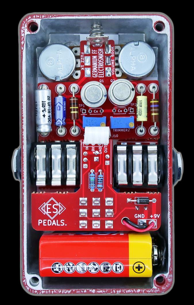
8 STEP 7 Check the Board: Make sure that your board looks exactly like the one below: Note: The LED is still not soldered, once inside the enclosure you can adjust the perfect length for the leads and solder it. Note: The 100pF Cx Miller capacitors are optional. They help to reduce the noise of the pedal but also may affect the fuzz tone. You can try them, although the original Fuzz did not include these parts as the effect was made to be organically noisy. This is the perfect time to try the pedal and make sure that works and sounds good.


 using double side tape, they will")
9 STEP 8 Boxing Now that the electronics are finished, let s prepare the enclosure. The Germanium Fuzz uses a standard Hammond 1590B. You can use a pre-drilled box or drill your own using the 1590B Germanium Fuzz Stencil. Use a cutter to separate the stickers and place the black pad on the bottom: At the last page of this document, you can see how the stickers are placed. Place the 2 plastic insulators (one need to be cut following the stencil) using double side tape, they will protect the electronics: Leave the battery area free from insulation Cut following the stencil

10 After placing the 5mm metal LED holder, you need to box the electronics, take your time and be patient: Make sure that all the soldered parts have their legs cut as close as possible to the PCB Don t force the parts into the holes be gentle-, they are designed to be tight but not forced. If they seem to be stuck, remove the electronics and start again. The best way to enclose the board is to try to fit all the parts through the holes at the same time (not simply inserting one jack after the other). It is easier is you start with the 2 jacks, the LED and the footswitch (inserting the 4 of them on the holes at the same time). Note: The LED has to be placed but not soldered yet. The negative pin (shorter on the flat side of the LED) goes into the square hole, and the positive pin into the upper round hole. When all is in place, you can finally fit the washers & nuts and solder the red LED.


11 This is the final finished project:
Guitarpedalkits.com Overdrive Pedal Build Instructions
 Page 1 Guitarpedalkits.com Overdrive Pedal Build Instructions Follow the instructions in this guide to build your very own DIY overdrive pedal from GuitarPedalKits.com. If you re a first time builder,
Axis Fuzz Kit Building Manual
 Axis Fuzz Kit Building Manual Effect Pedal Kits: Axis Fuzz The Axis Fuzz Kit is based in the Roger Mayer Axis Fuzz, the effect pedal responsible for Jimi Hendrix sound in Axis Bold As Love. What else is
Rangemaster Treble Booster Kit Building Manual
 Rangemaster Treble Booster Kit Building Manual Effect Pedal Kits: Rangemaster Treble Booster The Dallas Rangemaster is the most famous treble booster effect pedal, and it was the first pedal of its kind.
BUILD YOUR OWN. Fuzz Face SUPER-FREQ.COM
 BUILD YOUR OWN Fuzz Face SUPER-FREQ.COM CHAPTER 1 The Fuzz Face By Mitchell Hudson of super-freq.com, in conjunction with Joe Gore of tonefiend.com. Build your own vintage Fuzz Face! Create a vintage-style
MICROGRANNY v2.1 - Assembly Guide
 last update: 9. 5. 2017 MICROGRANNY v2.1 - Assembly Guide bastl-instruments.com INTRODUCTION Welcome to the assembly guide for the MicroGranny kit. MicroGranny is a monophonic granular sampler by Bastl
Value Location Qty Potentiometers C1M Distortion 1 A10k Volume 1. Footswitch 3PDT SW1 1. Jacks 1/4 Mono 2 DC Power 1
 Distortion BUILD INSTRUCTIONS Thank you for your purchase of our Distortion+ kit! We have completely redesigned our entire line of kits to be the most user friendly, while still maintaining their same
Build Your Own Clone Mouse Kit Instructions
 Build Your Own Clone Mouse Kit Instructions Warranty: BYOC, Inc. guarantees that your kit will be complete and that all parts and components will arrive as described, functioning and free of defect. Soldering,
THE THUNDERDRIVE (K-950)
") THE THUNDERDRIVE (K-950) OUTPUT DISTORTION Unplug when not in use to save battery life. TO AMP IN The Thunderdrive Modkitsdiy.com FROM GUITAR OUT Use these instructions to learn: How to build an effects
THE THUNDERDRIVE (K-950) OUTPUT DISTORTION Unplug when not in use to save battery life. TO AMP IN The Thunderdrive Modkitsdiy.com FROM GUITAR OUT Use these instructions to learn: How to build an effects
LA502 Assembly guide Main PCB Resistors - (2)
") LA502 Assembly guide Safety warning The kits are main powered and use potentially lethal voltages. Under no circumstance should someone undertake the realisation of a kit unless he has full knowledge about
LA502 Assembly guide Safety warning The kits are main powered and use potentially lethal voltages. Under no circumstance should someone undertake the realisation of a kit unless he has full knowledge about
Build Your Own Clone B.G. Fuzz Kit Instructions
 Build Your Own Clone B.G. Fuzz Kit Instructions Warranty: BYOC, Inc. guarantees that your kit will be complete and that all parts and components will arrive as described, functioning and free of defect.
Electric Druid Flangelicious Flanger Project
 Electric Druid Flangelicious Flanger Project (Using either 4KNOBFLANGE or MULTIFLANGE chips) Overview! 2 Build Instructions! 2 Populate the PCB! 2 1N4148 Diodes! 2 Resistors! 2 Cup of tea and soldering
TS500 Assembly guide. Soldering. TS500 Assembly guide Main PCB 1. Diodes. Document revision 1.2 Last modification : 17/12/16
 TS500 Assembly guide Safety warning The kits are main powered and use potentially lethal voltages. Under no circumstance should someone undertake the realisation of a kit unless he has full knowledge about
Value Location Qty Transistors 2N5485 Q1, Q2, 4 Q3, Q4 2N5087 Q5 1. Trim Pots 250k VTRIM 1. Potentiometers C500k Speed 1. Toggle Switch On/On Vibe 1
 P-90 BUILD INSTRUCTIONS Thank you for your purchase of our P-90 kit! We have completely redesigned our entire line of kits to be the most user friendly, while still maintaining their same great sound!
Build Your Own Clone The Swede Kit Instructions
 Build Your Own Clone The Swede Kit Instructions Warranty: BYOC, Inc. guarantees that your kit will be complete and that all parts and components will arrive as described, functioning and free of defect.
THE RING RESONATOR (K-975)
") THE RING RESONATOR (K-975) OUTPUT BOOST The Ring Resonator An Octave Up Fuzz Modkitsdiy.com 9 VDC CENTER (-) ADAPTER TO AMP IN FROM GUITAR OUT Unplug when not in use to save battery life. Use these instructions
THE RING RESONATOR (K-975) OUTPUT BOOST The Ring Resonator An Octave Up Fuzz Modkitsdiy.com 9 VDC CENTER (-) ADAPTER TO AMP IN FROM GUITAR OUT Unplug when not in use to save battery life. Use these instructions
LDB-1 Kit Instructions Page 1 of 8
 LDB-1 Kit Instructions Page 1 of 8 Important Information Congratulations and thank you for your purchase of the LDB-1 Little Drummer Boy Analog Drum Machine Kit! Before you start, please read the enclosed
BYOC Vibrato Kit Instructions BA662A version
 BYOC Vibrato Kit Instructions BA662A version Please read these instructions very thoroughly before building even if you are an experience builder. Because of the layout, there is a certain order which
GuitarPCB.com Angry Red Camel Build Instructions
 GuitarPCB.com Angry Red Camel Build Instructions Board Dimensions (W x H) 1.95 x 1.65 inches, i.e.: 49.5 x 41.9mm. This design will fit into a 1290NS/1590B size enclosure or larger. This is a variant of
Build Your Own Clone Li l Reverb Kit Instructions
 Build Your Own Clone Li l Reverb Kit Instructions Warranty: BYOC, Inc. guarantees that your kit will be complete and that all parts and components will arrive as described, functioning and free of defect.
Ultimatum Fuzz. The Ultimate experience in vintage-style octave-up fuzz
 Ultimatum Fuzz The Ultimate experience in vintage-style octave-up fuzz Contents of this document are 2015 Pedal Parts Ltd. No reproduction permitted without the express written permission of Pedal Parts
Penrose Quantizer Assembly Guide
 Penrose Quantizer Assembly Guide Schematic and BOM The schematic can be found here: www.sonic-potions.com/public/penrosequantizerschematic.pdf The BOM is available at google docs: Link to BOM Prepare the
THE AGGRESSOR (K-995)
") THE AGGRESSOR (K-99) TONE VOLUME DISTORTION MID-SHIFT SWITCH LED The Aggressor Distortion Pedal Modkitsdiy.com 9 VDC CENTER (-) ADAPTER TO AMP IN FROM GUITAR OUT Unplug when not in use to save battery
THE AGGRESSOR (K-99) TONE VOLUME DISTORTION MID-SHIFT SWITCH LED The Aggressor Distortion Pedal Modkitsdiy.com 9 VDC CENTER (-) ADAPTER TO AMP IN FROM GUITAR OUT Unplug when not in use to save battery
Build Your Own Clone Green Pony Kit Instructions
 Build Your Own Clone Green Pony Kit Instructions Warranty: BYOC, Inc. guarantees that your kit will be complete and that all parts and components will arrive as described, functioning and free of defect.
GCI BRUTALIST JR. BUILD GUIDE
 GCI BRUTALIST JR. BUILD GUIDE The Brutalist Jr. is the DIY little brother to the GCI Brutalist, a high powered distortion pedal loosely based on the Providence Stampede SDT-1. It runs on 9v DC power or
Assembly and User Guide
 Assembly and User Guide AtariPunkr is an adjustable stepped tone generator. AtariPunkr provides hours of fun everyone! Powered by: 9V Battery Outputs: Mylar Speaker (Included) Stereo Output (3.5mm Jack)
Build Your Own Clone Li l Echo Kit Instructions
 Build Your Own Clone Li l Echo Kit Instructions Warranty: BYOC, Inc. guarantees that your kit will be complete and that all parts and components will arrive as described, functioning and free of defect.
Build Your Own Clone Kuzco Jr. Kit Instructions
 Build Your Own Clone Kuzco Jr. Kit Instructions Warranty: BYOC, Inc. guarantees that your kit will be complete and that all parts and components will arrive as described, functioning and free of defect.
Build Your Own Clone Classic Phaser Kit Instructions
 Build Your Own Clone Classic Phaser Kit Instructions Warranty: BYOC, Inc. guarantees that your kit will be complete and that all parts and components will arrive as described, functioning and free of defect.
BYOC Vibrato Kit Instructions BA6110 version
 BYOC Vibrato Kit Instructions BA6110 version Please read these instructions very thoroughly before building even if you are an experience builder. Because of the
KASTLE v1.5 - Assembly Guide
 last update: 14. 12. 2017 KASTLE v1.5 - Assembly Guide bastl-instruments.com INTRODUCTION Welcome to the assembly guide for the Kastle kit - mini modular synthesizer. It is suitable for beginners. It is
Multiwave. Guitar Synthesizer. Build Document last updated november 2018 Version
 Multiwave Guitar Synthesizer Build Document last updated november 2018 Version 1.0 2018 The Multiwave is a guitar controlled oscillator with 3 different waveshapes: saw, triangle and square. Combined,
Build Your Own Clone Analog Chorus Kit Instructions
 Build Your Own Clone Analog Chorus Kit Instructions Warranty: BYOC, Inc. guarantees that your kit will be complete and that all parts and components will arrive as described, functioning and free of defect.
Build Your Own Clone Li l Comp Kit Instructions
 Build Your Own Clone Li l Comp Kit Instructions Warranty: BYOC, Inc. guarantees that your kit will be complete and that all parts and components will arrive as described, functioning and free of defect.
Build Your Own Clone Crown Jewel Kit Instructions
 Build Your Own Clone Crown Jewel Kit Instructions Warranty: BYOC, Inc. guarantees that your kit will be complete and that all parts and components will arrive as described, functioning and free of defect.
Build Your Own Clone Chancellor Kit Instructions
 Build Your Own Clone Chancellor Kit Instructions Warranty: BYOC, Inc. guarantees that your kit will be complete and that all parts and components will arrive as described, functioning and free of defect.
GuitarPCB.com Presents. Fuzzy Bee v2 (Pump d Up Edition) Build Instructions
 Build Instructions") GuitarPCB.com Presents Fuzzy Bee v2 (Pump d Up Edition) Build Instructions Board Dimensions (W x H) 2.13 x 1.67 i.e.: 54.0mm x 42.4mm. This design will fit into a 1290NS/1590B size enclosure or larger.
GuitarPCB.com Presents Fuzzy Bee v2 (Pump d Up Edition) Build Instructions Board Dimensions (W x H) 2.13 x 1.67 i.e.: 54.0mm x 42.4mm. This design will fit into a 1290NS/1590B size enclosure or larger.
The Engineer s Thumb Compressor/Limiter ValveWizard PCB User Guide (Issue 3 PCBs)
") The Engineer s Thumb Compressor/Limiter ValveWizard PCB User Guide (Issue 3 PCBs) Fig. 1: Circuit schematic Fig. 2: Component layout Fig. 3: Wiring diagram (with millennium bypass) Before populating the
The Engineer s Thumb Compressor/Limiter ValveWizard PCB User Guide (Issue 3 PCBs) Fig. 1: Circuit schematic Fig. 2: Component layout Fig. 3: Wiring diagram (with millennium bypass) Before populating the
Electric Druid 4 second Digital Delay Project
 Electric Druid 4 second Digital Delay Project Overview! 2 Build Instructions! 2 Populate the PCB! 2 Resistors! 2 Cup of tea and soldering check! 3 Power protection diode! 4 Ground link wire! 4 IC sockets!
Build Your Own Clone Li l Beaver (Ram s Head) Kit Instructions
 Kit Instructions") Build Your Own Clone Li l Beaver (Ram s Head) Kit Instructions Warranty: BYOC, Inc. guarantees that your kit will be complete and that all parts and components will arrive as described, functioning and
Build Your Own Clone Li l Beaver (Ram s Head) Kit Instructions Warranty: BYOC, Inc. guarantees that your kit will be complete and that all parts and components will arrive as described, functioning and
Build Guide CascadiA. GeFet Preamp
 Build Guide CascadiA GeFet Preamp Disclaimery stuff: This project is meant to be assembled by fellow DIYers from the Madbean forum and should only be used for the forces of good. Any other uses prohibited
ABC V1.0 ASSEMBLY IMPORTANT!
 ABC V1.0 ASSEMBLY Before starting this kit, prepare the following tools: Soldering iron (15-20W will do), flush cutters, no.2 hex screwdriver or allen key and phillips screwdriver. Also briefly go through
Manual Version July 2007
 Manual Version 1.2 - July 2007 Page 1 Table of Contents Section1: M3 Phono Board Build...3 Phono Board Parts List...3 Preparation...4 Fitting the Valve Bases...6 Installing the Resistors...7 Starting the
Glue Fuzz Mounting instructions.
 Glue Fuzz Mounting instructions. Index Important notice. 2 What's in the kit? 3 What you'll need. 4 Soldering on the pcb. 4 Wiring the pedal. 11 Test the board. 12 Debugging chapter. 13 Copyright Zorg
IR add-on module circuit board assembly - Jeffrey La Favre January 27, 2015
 IR add-on module circuit board assembly - Jeffrey La Favre January 27, 2015 1 2 For the main circuits of the line following robot you soldered electronic components on a printed circuit board (PCB). The
Build Your Own Clone Silver Pony 2 Kit Instructions
 Build Your Own Clone Silver Pony 2 Kit Instructions Warranty: BYOC, Inc. guarantees that your kit will be complete and that all parts and components will arrive as described, functioning and free of defect.
THE STEP LADDER (K-978)
") THE STEP LADDER (K-978) Footswitch True-bypass = 0 db OUTPUT INPUT Ground shunt switching on the input jack keeps the amp quiet when unplugged from the Step Ladder. Attenuator Pot Full clockwise = 0 db
THE STEP LADDER (K-978) Footswitch True-bypass = 0 db OUTPUT INPUT Ground shunt switching on the input jack keeps the amp quiet when unplugged from the Step Ladder. Attenuator Pot Full clockwise = 0 db
THE TRILL TREMOLO (K-960)
") THE TRILL TREMOLO (K-60) DEPTH SPEED The Trill Tremolo Modkitsdiy.com Unplug when not in use to save battery life. TO AMP IN FROM GUITAR OUT Use these instructions to learn: How to build an effects pedal
THE TRILL TREMOLO (K-60) DEPTH SPEED The Trill Tremolo Modkitsdiy.com Unplug when not in use to save battery life. TO AMP IN FROM GUITAR OUT Use these instructions to learn: How to build an effects pedal
Jour de FET Mounting instructions.
 Jour de FET Mounting instructions. Summary Important notice. What's in the kit? What you'll need. Soldering on the pcb. Wiring the pedal. Test the board. Debugging chapter. Hacks!!! 3 4 4 3 5 6 Copyright
Build Your Own Clone 27V Boost Kit Instructions
 Build Your Own Clone 27V Boost Kit Instructions Warranty: BYOC, Inc. guarantees that your kit will be complete and that all parts and components will arrive as described, functioning and free of defect.
Build Your Own Clone Silver Pony Kit Instructions
 Build Your Own Clone Silver Pony Kit Instructions Warranty: BYOC, Inc. guarantees that your kit will be complete and that all parts and components will arrive as described, functioning and free of defect.
Chunky Cheese Build Guide Rev
 Chunky Cheese Build Guide Rev. 2008-08-04 The Chunky Cheese is a slightly-modified version of the discontinued Big Cheese fuzz pedal. Table of Contents Table of Contents... 1 PCB Layout... 2 Parts List...
Bill of Materials: PWM Stepper Motor Driver PART NO
 PWM Stepper Motor Driver PART NO. 2183816 Control a stepper motor using this circuit and a servo PWM signal from an R/C controller, arduino, or microcontroller. Onboard circuitry limits winding current,
INTO THE UNKNOWN Build Document last updated may 2016 Version
 INTO THE UNKNOWN Build Document last updated may 2016 Version 1.0 2015 'Into the Unknown Guitar Synthesizer Deluxe' is a CMOS based fuzz centered around the CD4046 PLL (phase locked loop) chip and a CD4015
Wiring Manual NEScaf April 2010 (August 2006)
") Wiring Manual NEScaf April 2010 (August 2006) Switched Capacitor Audio Filter The NEScaf is a switched capacitor audio filter (acronym SCAF) built around a building-block type filter chip. The NEScaf will
Wiring Manual NEScaf April 2010 (August 2006) Switched Capacitor Audio Filter The NEScaf is a switched capacitor audio filter (acronym SCAF) built around a building-block type filter chip. The NEScaf will
Build Your Own Clone Li l Analog Chorus Kit Instructions
 Build Your Own Clone Li l Analog Chorus Kit Instructions Warranty: BYOC, Inc. guarantees that your kit will be complete and that all parts and components will arrive as described, functioning and free
Build Your Own Clone Mega Chorus & Vibrato Kit Instructions
 Build Your Own Clone Mega Chorus & Vibrato Kit Instructions Warranty: BYOC, Inc. guarantees that your kit will be complete and that all parts and components will arrive as described, functioning and free
Build Your Own Clone Spring Reverb Kit Instructions
 Build Your Own Clone Spring Reverb Kit Instructions Warranty: BYOC, Inc. guarantees that your kit will be complete and that all parts and components will arrive as described, functioning and free of defect.
Build Your Own Clone Classic Overdrive Kit Instructions
 Build Your Own Clone Classic Overdrive Kit Instructions Warranty: BYOC, LLC guarantees that your kit will be complete and that all parts and components will arrive as described, functioning and free of
Building the Toothpick Audio CW Filter
 Building the Toothpick Audio CW Filter Introduction The toothpick is a simple variable bandpass audio filter designed to compliment the Splinter QRPp Trans-Receiver. The filter also contains an audio amplifier
Build Your Own Clone Parametric Multi-Band Compressor Kit Instructions
 Build Your Own Clone Parametric Multi-Band Compressor Kit Instructions Warranty: BYOC, Inc. guarantees that your kit will be complete and that all parts and components will arrive as described, functioning
Mono Amplifier. LM386 Headphone Amp
 Mono Amplifier LM386 Headphone Amp Layout On/Off Switch - cuts power to the circuit Mono Input Jack: use either L or R or solder together Schematic Step 1 - Parts List 1.) R1-10ohm Resistor - Brown Black
The Walford Electronics Ford Receiver Kit Project Construction Manual
 The Walford Electronics Ford Receiver Kit Project Construction Manual Walford Electronics Ford Receiver construction manual V1.5 Page 1 of 22 Introduction The Ford receiver has four stages: The first stage
Heartboard PCB Assembly Instructions
 Heartboard PCB Assembly Instructions Thanks for purchasing a Heartboard! These instructions will guide you through assembling and testing the Heartboard. Let s get started! Stuff you need Soldering iron
Foxhunt Offset Attenuator. Parts List:
 When your closing in on the fox you may find the signals to be so strong that you can no longer find a peak or null with your antenna. Sometimes the signal is so strong that the RF will leak straight into
How to build a Cracklebox. Red Wierenga Brooklyn College Center for Computer Music October 13, 2015
 How to build a Cracklebox Red Wierenga Brooklyn College Center for Computer Music October 13, 2015 What s a Cracklebox? What s a Cracklebox? The Cracklebox was developed by Michel Waisvisz and others at
REFRACTOR PROJECT NAME. BASED ON Klon Centaur / KTR. BUILD DIFFICULTY Intermediate. DOCUMENT VERSION Overdrive ( ) EFFECT TYPE
 EFFECT TYPE") PROJECT NAME REFRACTOR BASED ON Klon Centaur / KTR BUILD DIFFICULTY Intermediate EFFECT TYPE DOCUMENT VERSION Overdrive 1.0.0 (2018-08-12) PROJECT SUMMARY A part-for-part replica of a mythical overdrive
PROJECT NAME REFRACTOR BASED ON Klon Centaur / KTR BUILD DIFFICULTY Intermediate EFFECT TYPE DOCUMENT VERSION Overdrive 1.0.0 (2018-08-12) PROJECT SUMMARY A part-for-part replica of a mythical overdrive
LITTLE NERD v1.1 Assembly Guide
 last update: 9. 3. 2016 LITTLE NERD v1.1 Assembly Guide bastl instruments.com INTRODUCTION This guide is for building Little Nerd module from Bastl Instruments. It is good to have basic soldering skills
Build Your Own Clone Li l Pony Kit Instructions
 Build Your Own Clone Li l Pony Kit Instructions Warranty: BYOC, Inc. guarantees that your kit will be complete and that all parts and components will arrive as described, functioning and free of defect.
Total solder points: 79 Difficulty level: beginner advanced GUITAR PREAMPLIFIER WITH HEADPHONE OUTPUT K4102 ILLUSTRATED ASSEMBLY MANUAL
 Total solder points: 79 Difficulty level: beginner 1 2 3 4 5 advanced GUITAR PREAMPLIFIER WITH HEADPHONE OUTPUT K4102 Practice the guitar without disturbing others. ILLUSTRATED ASSEMBLY MANUAL H4102IP-1
Build Your Own Clone Tremolo Kit Instructions
 Build Your Own Clone Tremolo Kit Instructions Warranty: BYOC, LLC guarantees that your kit will be complete and that all parts and components will arrive as described, functioning and free of defect. Soldering,
MP573 Assembly guide. Soldering. MP573 Assembly guide PCB split PCB split. Document revision 2.2 Last modification : 22/08/17
 MP573 Assembly guide Safety warning The kits are main powered and use potentially lethal voltages. Under no circumstance should someone undertake the realisation of a kit unless he has full knowledge about
Build Your Own Clone Analog Vibrato Kit Instructions
 Build Your Own Clone Analog Vibrato Kit Instructions Warranty: BYOC, Inc. guarantees that your kit will be complete and that all parts and components will arrive as described, functioning and free of defect.
Build Your Own Clone Reverb Kit Instructions
 Build Your Own Clone Reverb Kit Instructions Warranty: BYOC, LLC guarantees that your kit will be complete and that all parts and components will arrive as described, functioning and free of defect. Soldering,
TV Remote. Discover Engineering. Youth Handouts
 Discover Engineering Youth Handouts Electronic Component Guide Component Symbol Notes Amplifier chip 1 8 2 7 3 6 4 5 Capacitor LED The amplifier chip (labeled LM 386) has 8 legs, or pins. Each pin connects
Digital Electronics & Chip Design
 Digital Electronics & Chip Design Lab Manual I: The Utility Board 1999 David Harris The objective of this lab is to assemble your utility board. This board, containing LED displays, switches, and a clock,
Bill of Materials: Metronome Kit PART NO
 Metronome Kit PART NO. 2168325 The metronome kit allows you to build your own working electronic metronome. Features include a small speaker, flashing LED, and the ability to switch between several different
Build Your Own Clone Li l Beaver (Triangle Version) Kit Instructions
 Kit Instructions") Build Your Own Clone Li l Beaver (Triangle Version) Kit Instructions Warranty: BYOC, Inc. guarantees that your kit will be complete and that all parts and components will arrive as described, functioning
Build Your Own Clone Li l Beaver (Triangle Version) Kit Instructions Warranty: BYOC, Inc. guarantees that your kit will be complete and that all parts and components will arrive as described, functioning
Slow Century Build Guide
 Slow Century Build Guide In 1986, Michael Soldano founded an amp company in Los Angeles. Known for high-gain designs, Soldano has produced a number of amps that have been critical successes with a huge
DIODE / TRANSISTOR TESTER KIT
 DIODE / TRANSISTOR TESTER KIT MODEL DT-100K Assembly and Instruction Manual Elenco Electronics, Inc. Copyright 1988 Elenco Electronics, Inc. Revised 2002 REV-K 753110 DT-100 PARTS LIST If you are a student,
Eurorack DIY Kit Instructions. All Thonk kits are sold under our standard Terms and Conditions -
 MA VCA OVERVIEW For the most recent version of this document please visit http://thonk.co.uk/documents/ma/ For all technical support please visit http://bit.ly/1tl78e0 on Muffwiggler. All Thonk kits are
Build your own boombox
 Build your own boombox This amplifier kit with plug-in board and all necessary components is easy and quick to assemble, requires no soldering and is great fun. Listen to your favourite music with your
UK-electronic 2008/13
 UK-electronic 2008/13 Assembly manual for Kit BOR Clone Rev. 1.22 (2N7000) Ver. 2014 Page 3...Bill of material Page 4..5...soldering the pcb Page 5...pcb layout top Page 6...wiring diagram Page 7..8...enclosure,
Build Your Own Clone Divided Octave Kit Instructions
 Build Your Own Clone Divided Octave Kit Instructions Warranty: BYOC, Inc. guarantees that your kit will be complete and that all parts and components will arrive as described, functioning and free of defect.
Pacific Antenna Wall Wart Tamer 2.0 Kit
 Pacific Antenna Wall Wart Tamer 2.0 Kit Description The Wall Wart Tamer lets you utilize those surplus computer and wall pack power supplies as a clean, adjustable voltage, DC power source for radios and
Electronics Merit Badge Class 4. 12/30/2010 Electronics Merit Badge Class 4 1
 Electronics Merit Badge Class 4 12/30/2010 Electronics Merit Badge Class 4 1 Soldering Safety Note: A Soldering Iron gets hotter than 374 F. Do not touch the soldering iron s metal parts or you will receive
New Jersey Jr Electric Guitar DIY Kit
 New Jersey Jr Electric Guitar DIY Kit Thank you for purchasing this DIY Guitar Kit. The following instructions specify how to assemble your guitar. There are a variety of finishes that can be applied to
Brooklyn DIY Guitar Kit
 Brooklyn DIY Guitar Kit Thank you for purchasing this DIY Guitar Kit. The following instructions specify how to assemble your guitar. There are a variety of finishes that can be applied to the guitar,
Pacific Antenna Code Practice Oscillator Kit
 Pacific Antenna Code Practice Oscillator Kit This kit is offered to initiate the first time builder in the various techniques of mechanical and electronic kit construction. At the end of the approximately
Construction notes for the symmetrical 400 watt amplifier
 Construction notes for the symmetrical 400 watt amplifier Introduction The symmetrical amplifier is an update of one of my designs, which appeared in the Australian electronics magazine Silicon Chip in
Pacific Antenna Field Strength Indicator Kit
 Pacific Antenna Field Strength Indicator Kit Description The Field Strength Indicator kit from Pacific Antenna provides a visual way to monitor the presence and relative strength RF fields through the
PAT-4 POWER SUPPLY ASSEMBLY MANUAL Rev B Version
 PAT-4 POWER SUPPLY ASSEMBLY MANUAL Rev B Version 2013 AkitikA, LLC All rights reserved Revision Bp01 November 3, 2013 Page 1 of 16 Table of Contents Table of Contents... 2 Table of Figures... 2 Section
4ms SCM Breakout. Kit Builder's Guide for PCB v2.1 4mspedals.com
 4ms SCM Breakout Kit Builder's Guide for PCB v2.1 4mspedals.com Shuffling Clock Multiplier Breakout This guide is for building a Shuffling Clock Multiplier Breakout module (SCMBO) version 2.1 from the
NEW WAVE CV GENERATOR Build Document last updated september 2017 for PCB version 1.0
 NEW WAVE CV GENERATOR Build Document last updated september 2017 for PCB version 1.0 The New Wave is a Control Voltage Generator. It has two LFO's (low frequency oscillators) and four different output
Read This Page First
 Read This Page First If you are reading this you know the manuals are always available at QRPKITS.com. This is version 8.0 of the manual dated 4/27/2016. There is no need to print out the whole assembly
THE PILEDRIVER (K-920)
") THE PILERIVER (K-90) Unplug when not in use to save battery life. TO AMP IN www.modkitsdiy.com FROM UITAR OUT Use these instructions to learn: How to build an effects pedal for clean boost. The Pileriver
THE PILERIVER (K-90) Unplug when not in use to save battery life. TO AMP IN www.modkitsdiy.com FROM UITAR OUT Use these instructions to learn: How to build an effects pedal for clean boost. The Pileriver
Circuit Board Assembly Instructions for Babuinobot 1.0
 Circuit Board Assembly Instructions for Babuinobot 1.0 Brett Nelson January 2010 1 Features Sensor4 input Sensor3 input Sensor2 input 5v power bus Sensor1 input Do not exceed 5v Ground power bus Programming
Myriad Design Altoids Piezo Preamp Construction Guide
 Myriad Design Altoids Piezo Preamp Construction Guide V2 December, 2014 1. The package should include the following items. If any of the items are missing from the package, please contact sales@stompville.co.uk.
SoftRock v5.0 Builder s Notes. December 12, Building a QSD Kit
 SoftRock v5.0 Builder s Notes December 12, 2005 Building a QSD Kit Be sure to use a grounded tip soldering iron in building the QSD board. The soldering iron needs to have a small tip, (0.05-0.1 inch diameter),
Never power this piano with anything other than a standard 9V battery!
 Welcome to the exciting world of Digital Electronics! Who is this kit intended for? This kit is intended for anyone from ages 13 and above and assumes no previous knowledge in the field of hobby electronics.
Assembly Instructions for the 1.5 Watt Amplifier Kit
 Assembly Instructions for the 1.5 Watt Amplifier Kit 1.) All of the small parts are attached to a sheet of paper indicating both their value and id. 2.) Leave the parts affixed to the paper until you are