Dig Dug madbeanpedals FX Type: Sequencer W x 3.25 H
|
|
|
- Silvester Nichols
- 6 years ago
- Views:
Transcription

1 Dig Dug madbeanpedals FX Type: Sequencer 4.15 W x 3.25 H
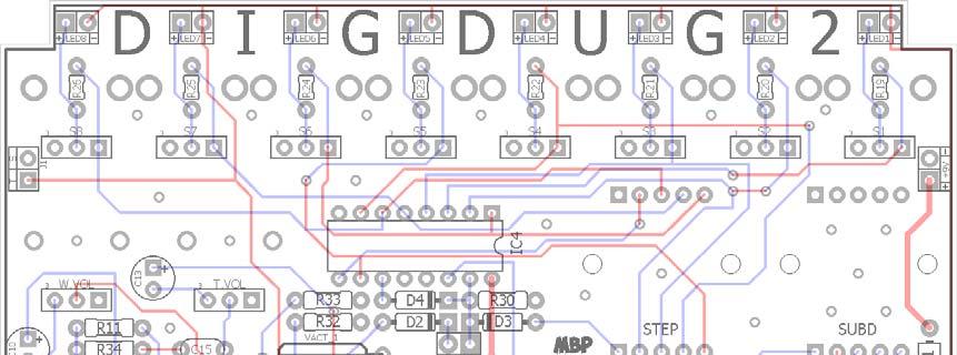
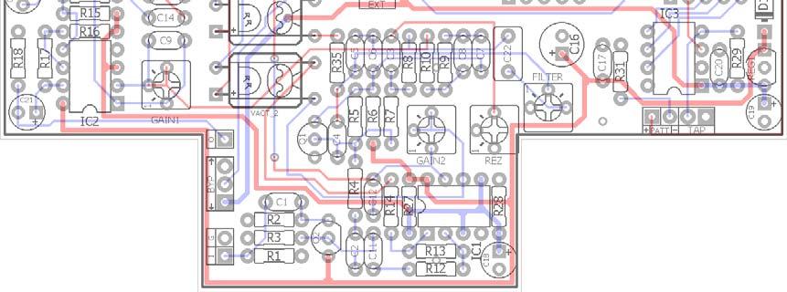
2 B.O.M. Resistors Caps Diodes R1 1M C1 100n D1 1N5817 R2 1M C2 220n D2 - D4 1n914 R3 10k C3 15n LED1-8 3mm Red R4 330k C4 2n2 PATT 3mm Red R5 4M7 C5 6n8 Transistors R6 10k C6 100n Q1 2N5088 R7 180k C7 100n Q2 2n5457 R8 180k C8 22n IC's R9 10k C9 100pF IC1 TL072 R10 10k C10 1uF IC2 TL072 R11 10k C11 220n IC3 MV-52B R12 10k C12 100pF IC4 CD4017 R13 20k C13 1uF Regulator R14 100R C14 100n REG1 LM78L05 R15 10k C15 100n Switches R16 10k C16 100uF STEP 1P8T R17 20k C17 100n SUBD 2P4T R18 100k C18 10uF EXT SPST R19 330R C19 10uF TAP Mom. R20 330R C20 100n Jack R21 330R C21 1uF J1 1/"8 Jack R22 330R C22 220n Vactrols R23 330R VACT_1 VTL5C9 R24 330R VACT_2 VTL5C3 R25 330R Trimmers R26 330R GAIN1 50k R27 10k GAIN2 50k R28 10k FILTER 100k R29 10k REZ 100k R30 100k Pots R31 1k W.VOL 100kB R32 330R T.VOL 100kB R33 330R S1 - S8 2kB R34 10k R35 220R 2
3 Shopping List Value QTY Type Rating 100R 1 Carbon / Metal Film 1/4W 220R 1 Carbon / Metal Film 1/4W 330R 10 Carbon / Metal Film 1/4W or 1/8W 1k 1 Carbon / Metal Film 1/4W 10k 12 Carbon / Metal Film 1/4W 20k 2 Carbon / Metal Film 1/4W 100k 2 Carbon / Metal Film 1/4W 180k 2 Carbon / Metal Film 1/4W 330k 1 Carbon / Metal Film 1/4W 1M 2 Carbon / Metal Film 1/4W 4M7 1 Carbon / Metal Film 1/4W 100pF 2 Ceramic 16v min. 2n2 1 Film 16v min. 6n8 1 Film 16v min. 15n 1 Film 16v min. 22n 1 Film 16v min. 100n 7 Film 16v min. 220n 3 Film 16v min. 1uF 3 Electrolytic 16v min. 10uF 2 Electrolytic 16v min. 100uF 1 Electrolytic 16v min. 1N n mm Red 9 Diffused LED 2N n TL072 2 MV-52B 1 CD LM78L05 1 1P8T 1 1 pole 8 pos. rotary 2P4T 1 2 pole, 4 pos. Rotary SPST 1 mini-switch (SPDT okay) Mom. 1 Momentary footswitch J1 1 Jack 1/8" VTL5C9 1 VTL5C3 1 50k 2 Bourns 3362P 100k 2 Bourns 3362P 100kB 2 PCB Right Angle, metal shaft 9mm 2kB 8 PCB Right Angle, plastic shaft 9mm 3
4 MV-52B VTL5C9 VTL5C3 CD Plastic Shaft pots Metal Shaft pots SPDT mini switch Momentary switch 1/8 jack or, 1P8T N/?qs=sGAEpiMZZMvNbjZ2WlReYqBsoziRjTWUH8saZNpNioA%3d 2P4T N/?qs=sGAEpiMZZMvNbjZ2WlReYqBsoziRjTWUDACTxOT1rRE%3d If you cannot get a VTL5C9 for VACT_1, use the VTL5C3 in its place. 4
5 5
6 125BB Drilling Guide 7.48 W x 6.47 H Photoshop template: 6
7 Wiring Diagram 7
8 What Is It? The DigDug2 is a multi-function tap-based sequencer. It can be used as a wah and/or tremolo. It can also drive an external optical-based modulation circuit. How Does It Work? The DigDug2 utilizes the Molten Voltage MV-52B chip. It converts a tap input into a time-based pulse. This pulse is fed to the CD4017 counter. The CD4017, in turn, outputs a 5v pulse in a linear sequence which lights up the corresponding LED connected to it. This allows us to use an opticalbased effect where each step in the sequence corresponds to an individually controlled LED. The relative brightness of those LEDs creates a sequence, or pattern, of audio effects. Think of the LEDs as individual depth controls for the effects. How Do I Use It? The DigDug2 has two on-board effects; a tremolo and a wah. These can be used independent of one another or in parallel. The tremolo and wah have only one external control each: a volume control. However, there are several internal trimmers that allow you to shape these effects further. Each sequence step has its own knob, S1 S8. The knobs control the brightness of the LED driven by that particular step. To operate the DigDug2, first you set the subdivision and step rotary switches to the desired setting. The Step switch can be set anywhere from 1 to 8 steps. The Subdivision switch has four settings based on the tap-tempo input; ½, 1x, 2x, and 4x. So, a ½ settings will set the sequence speed to ½ the tapped input, and 4x will change it to four times the tapped input. Next you manipulate the corresponding pots for the number of steps chosen to change the brightness of their LEDs. The relative brightness of each LED defines the rhythmic pattern one creates once the steps are played in sequence. TIP: Think of each step as a subdivision of a note. If we think of the 8 steps as two whole notes, then each LED corresponds to a 16 th note. The brightness of each LED in the two whole note sequence allows us to create a 16 th note pattern where each subdivision can be on, off, or somewhere in-between. Or, if using 6 steps, you could consider each step a triplet in a pair of two whole notes. It sounds a lot more complicated than it is trust me. After the switch and pattern settings are chosen, simply engage the Tap footswitch two or more times to set the tempo (rate) of the sequence. Finally, set the desired volume level for the Tremolo or Wah effects. Tip: You need at least two steps for the tremolo effect. For the wah, you can set it to Step 1 for a stuck wah setting. There is secondary output for the sequencer that can be used to drive an external optical effect. Connect a 1/8 mono plug from the DigDug2 to an external LED used in another effect. This assumes that you have another DIY project where this can be done, of course. While this document will not go into detail on how to construct a project based around that, I will provide enough info to get you started. Additionally, there will be a couple of future releases with the upcoming Tapanatorator project which will work with the DigDug2 (a vibrato and a phaser). Tip: The secondary output will not work with a PT2399 to control delay settings. At least not in the traditional sense of tapbased delay. 8
9 Controls W.Vol, T.Vol: External volume controls for the wah and tremolo, resp. SubD: Rotary switch that acts as a time multiplier. Use it to set the tapped input to ½, 1x, 2x or 4x speed. Step: Rotary switch that sets the number of steps desired in the sequence. You can have anything between 1 and 8 steps in a sequence. S1 S8: These pots control the brightness of the LED in each step. Counter-clockwise is full brightness. As each knob is turned up, the corresponding LED will dim in until fully off in the clockwise position. Most of the brightness manipulation will occur in the first ½ of the turn. After that the LED will go very dim and then off. Gain1, Gain2: The internal trimmers are for gain recovery for the tremolo and wah effects. This allows you to match the individual outputs to the external volume controls. In other words, when the W.Vol and T.Vol are set half-way up, the Gain1 and Gain2 trimmers are used so that the output volume of each effect is about the same. Matching the volume outputs will make the wah and tremolo effects much easier to control when used in parallel. Rez: This trimmer sets the resonant peak of the wah filter. Turning it up creates a sharper peak. Filter: This trimmer sets the center frequency of the wah filter. Counter-clockwise is a high filter. As the trimmer is turned up, the center frequency shifts downward for a darker filter. Ext: This switch selects between rest and run mode. Rest mode is the normal operation. In this mode, when the DigDug2 is put in bypass, the sequence is reset and stopped in the S1 position. When the effect is toggle on, the sequence begins again from the first step. In Run mode, the sequence keeps going whether or not the DigDug2 is in bypass. This mode allows you to use the sequencer to control an external modulation effect with the DigDug2 in bypass. You can still use the DigDug2 in run mode but 1) the pattern will continue from whichever step the sequence is in when you turn it on and 2) there is no indicator LED for the DigDug2 to tell you it's on when in Run mode. In rest mode, the running sequence indicates that the effect is on. Patt: This is a visual indicator that sums all the sequence steps into one LED. It s helpful to see your sequence in one spot rather than trying to follow up to eight LEDs at the same time. 9
10 Using the Secondary Output The 1/8 jack, J1, can send the sequence to an external effect. This allows the DigDug2 to control additional modulation effects that use optical drivers (such as vactrols or LED/LDR combos). Let s look at the schematic: J1 is connected in series with LED1-8 and in parallel with the PATT LED and the LEDs from the two vactrols that drive the tremolo and wah effects in the DigDug2. So, J1 is simply a place-holder for adding another LED as if we had three vactrols instead of two. This means we can use a 1/8 mono plug to carry the pulse outputs from the sequence to drive an external LED in another effect. How to do this? Very simple. Here are two possible ways: 10


11 The first way is a straight connection from J1 to another 1/8 jack on our external effect. Here the LED in the second effect is connected directly to the jack. This LED lights up whatever vactrol or LED/LDR combo you are using in the external modulation pedal. You ll notice that there is no current limiting resistor attached to the LED. That s okay because it is in series with LED1-8 on the DigDug2 and those act as current limiters for the new LED. The second way is basically the same, except here we have included a CLR on the LED for a bit more control. This CLR allows for more manipulation on the LED brightness in case it needs finetuning for the external effect. You could just as easily make this a trimmer, if you like. You ll notice I did the grounds differently in both examples. Either way is acceptable. Whether you use the ground connection from J1 or the ground in your external effect should not matter because we are simply controlling LED brightness here. There should be no interaction with the audio or power portions of either effect so a common ground is not required. 11
12 Voltages IC1 TL072 IC2 TL072 IC3 MV-52B varies varies varies varies varies IC4 CD4017 REG1 LM78L I G O Q1 2N C B E Q2 2N D S G 0 14 varies Power Supply: One Spot measuring 9.41vDC These readings were taken in bypass mode for a baseline. When the effect is on, the voltage readings on the CD4017 pins will fluctuate between 0 and about 4.77v as it goes through the sequence. 12


13 Build Guide This is a complicated build and requires patience and thoroughness to complete. Take your time, and above all test your build before you box it. Trust me, once this is boxed and wired you will never want to remove it. The Ext. switch must be mounted on the top wall with the other jacks. Normally I do not like switches on top but this is the only place for it to go. Use the mini-switch listed in the links under the BOM, if possible. You might be able to use a full sized SPDT but I haven t tried it. If possible, use 1/8W resistors for R19 R26. You can use 1/4W, but try to lay them flat as you can so the do not interfere with the input and output jacks. If you are like me and pretty well suck at drilling I suggest over-drilling the spots for the pots and rotary switches by one stop on a step drill bit (do not overdrill the LEDs, though). This will give you a bit of wiggle room when loading the PCB into your enclosure. The plastic shaft knobs are very unforgiving and if there is any contact between the enclosure and the pot shaft they will be difficult to turn. So, keep everything as centered as possible and drill slightly above what is required. The LEDs for S1-S8 are going to be a bit of a pain. In order to test the circuit, you need the LEDs soldered onto the PCB. But, it is pretty hard to get the exact length of leads needed on the LEDs for them to fit flush to the enclosure without testing them first! So, there are a few ways you can tackle this. 1) Populate the entire PCB except for the footswitches, wires and LEDs. Load LED1-8 loose into their spots on the PCB and then mount the PCB temporarily in the enclosure. Then you can move the LEDs into position so they are flush with the enclosure and solder them in place. Remove the PCB and finish your build. 2) Use sockets for LED1-8. This will let you trim the LED leads to exact lengths to ensure they fit flush to the enclosure. The shafts on the two rotary switches are manufactured longer than we need. This is easy to fix. Simply cut off a small portion of the plastic shaft with a wire cutter or scissors. 13

14 DigDug2 prototype 14
Dirtbaby FX TYPE: Delay Based on the EHX DMM 2016 madbeanpedals
 Dirtbaby FX TYPE: Delay Based on the EHX DMM 2016 madbeanpedals 3.325 W x 2.325 H Terms of Use: You are free to use purchased circuit boards for both DIY and small commercial operations. You may not offer
Cave Dweller 2015 edition FX Type: Delay 2015 madbeanpedals
 Cave Dweller 2015 edition FX Type: Delay 2015 madbeanpedals 1.3" W x 1.975" H (main board) Previous Version: http://www.madbeanpedals.com/projects/cavedweller/cavedweller_drill.zip Terms of Use: You are
Stage Fright 2015 edition FX TYPE: Phaser Based on the Maestro Phaser 2015 madbeanpedals
 Stage Fright 2015 edition FX TYPE: Phaser Based on the Maestro Phaser 2015 madbeanpedals 2.3" W x 3.45" H Previous Version: http://www.madbeanpedals.com/stagefright/stagefright.zip Terms of Use: You are
Liquid Mercury Phaser. Build doc V2.0
 Liquid Mercury Phaser Build doc V2.0 David Rolo / December 2014 The build consists of 2 boards that were designed to fit in a BB enclosure with top mounted open jacks. PCB1 holds the pcb mounted pots and
TWIN PEAKS TREMOLO. Build Guide for v3.1
 TWIN PEAKS TREMOLO Build Guide for v3.1 Revision 3.1 David Rolo 2017 Reference Quantity Value Description Switches Multiplier 1 1 pole 6 pos. rotary switch Shape 1 1 pole 8 pos. rotary switch Trem Type
VFE Choral Reef. FX TYPE: Chorus Images VFE and MBP Project Doc madbeanpedals Aug. 2 nd update see pg W x 2.05 H
 VFE Choral Reef FX TYPE: Chorus Images VFE and MBP Project Doc madbeanpedals Aug. 2 nd update see pg.4 2.17 W x 2.05 H Terms of Use: These projects are intended for DIY use only and may not be used in
Mobius Strip. FX TYPE: Dual Delay Images VFE and MBP Project Doc madbeanpedals W x H
 Mobius Strip FX TYPE: Dual Delay Images VFE and MBP Project Doc madbeanpedals 2.17 W x 2.025 H Note: Use the values listed on the image above not the values indicated on the silk-screen of the PCB. Some
2.15 W x 1.95 H. Changes to the 2015 edition
 NOM NOM FX Type: Filter 2015 edition Based on the MXR Phase 90 2015 madbeanpedals Download the previous version documentation here: http://www.madbeanpedals.com/projects/nomnom/nomnom.zip 2.15 W x 1.95
Total Recall FX Type: Delay Based on the EHX Deluxe Memory Man 2015 madbeanpedals
 Total Recall FX Type: Delay Based on the EHX Deluxe Memory Man 2015 madbeanpedals 3.34" W x 3.875" H Terms of Use: You are free to use purchased Total Recall circuit boards for both DIY and small commercial
FREEKOUT FX TYPE: Ring Modulator Based on the EHX Frequency Analyzer 2015 madbeanpedals
 FREEKOUT FX TYPE: Ring Modulator Based on the EHX Frequency Analyzer 2015 madbeanpedals 2.3 W x 3.025 H This project requires an 18v 100mA (or more) center tip negative power supply. I recommend the Dunlop
Weener Wah FX TYPE: Wah Wah Based on the Clyde McCoy 2016 edition madbeanpedals
 Weener Wah FX TYPE: Wah Wah Based on the Clyde McCoy 2016 edition madbeanpedals 1.95 W x 2.275 H Terms of Use: You are free to use purchased WeenerWah circuit boards for both DIY and small commercial operations.
Blueprint. FX TYPE: Delay Images VFE and MBP Project Doc madbeanpedals W x H
 Blueprint FX TYPE: Delay Images VFE and MBP Project Doc madbeanpedals 2.17 W x 2.025 H Note: Use the values listed on the image above not the values indicated on the silk-screen of the PCB. Some values
Blues King. FX TYPE: Overdrive Images VFE and MBP Project Doc madbeanpedals W x H
 Blues King FX TYPE: Overdrive Images VFE and MBP Project Doc madbeanpedals 2.17 W x 2.025 H Note: Use the values listed on the image above not the values indicated on the silk-screen of the PCB. Some values
Aquaboy FX TYPE: Delay Based on the Boss DM madbeanpedals
 Aquaboy FX TYPE: Delay Based on the Boss DM-2 2016 madbeanpedals 2.3 W x 3.125 H 1.29.17 Correction see page 6. Note: the M pad by the Delay pot is for modulation control (see the AB_MOD documentation
Tractor BEam. FX TYPE: Phaser Images VFE and MBP Project Doc madbeanpedals
 Tractor BEam FX TYPE: Phaser Images VFE and MBP Project Doc madbeanpedals 2.17 W x 2.02 H Note: This project is built on the Enterprise PCB. It s the same circuit as the Tractor Beam with a few value modifications.
Electric Druid Flangelicious Flanger Project
 Electric Druid Flangelicious Flanger Project (Using either 4KNOBFLANGE or MULTIFLANGE chips) Overview! 2 Build Instructions! 2 Populate the PCB! 2 1N4148 Diodes! 2 Resistors! 2 Cup of tea and soldering
Triumvirate. FX TYPE: Multi-Band Distortion Images VFE and MBP Project Doc madbeanpedals W x 2.01 H
 Triumvirate FX TYPE: Multi-Band Distortion Images VFE and MBP Project Doc madbeanpedals 2.17 W x 2.01 H Note: Use the values listed on the image above not the values indicated on the silk-screen of the
Guitarpedalkits.com Overdrive Pedal Build Instructions
 Page 1 Guitarpedalkits.com Overdrive Pedal Build Instructions Follow the instructions in this guide to build your very own DIY overdrive pedal from GuitarPedalKits.com. If you re a first time builder,
2015 ed. FX Type: Univibe 2015 madbeanpedals W x 3.29 H
 Harbinger One 2015 ed. FX Type: Univibe 2015 madbeanpedals 3.25 W x 3.29 H Harbinger One PCBs purchased form madbeanpedals may be used for small amounts of commercial building without prior consent. Keep
THE GREEN CURRANT TREMOLO Build Document last updated june 2017 for PCB version 1.5
 THE GREEN CURRANT TREMOLO Build Document last updated june 2017 for PCB version 1.5 The Green Currant tremolo is a very percussive and vibey tremolo based around the TDA7052A amplifier chip. It splits
PCB by 1776 Effects/JRM 2013 Circuit Design by Jon Patton
 Cardinal Tremolo PCB by 1776 Effects/JRM 2013 Circuit Design by Jon Patton The Cardinal Tremolo is a transistor and vactrol implementation of the Harmonic Tremolo. It resembles the harmonic tremolo from
FX Type: Distortion 1.95 W x H Terms of Use: Slow Loris Slow Loris
 Slow Loris 2015 edition madbeanpedals FX Type: Distortion Based on the ProCo Rat Changes for the 2015 edition: Slight layout adjustments. No circuit changes. Previous version: http://www.madbeanpedals.com/projects/slowloris/docs/slowloris.zip
NEW WAVE CV GENERATOR Build Document last updated september 2017 for PCB version 1.0
 NEW WAVE CV GENERATOR Build Document last updated september 2017 for PCB version 1.0 The New Wave is a Control Voltage Generator. It has two LFO's (low frequency oscillators) and four different output
Value Location Qty Potentiometers C1M Distortion 1 A10k Volume 1. Footswitch 3PDT SW1 1. Jacks 1/4 Mono 2 DC Power 1
 Distortion BUILD INSTRUCTIONS Thank you for your purchase of our Distortion+ kit! We have completely redesigned our entire line of kits to be the most user friendly, while still maintaining their same
VFE Merman. FX TYPE: Overdrive Images VFE and MBP Project Doc madbeanpedals W x H
 VFE Merman FX TYPE: Overdrive Images VFE and MBP Project Doc madbeanpedals 2.17 W x 2.025 H Note: Use the values listed on the image above not the values indicated on the silk-screen of the PCB. Some values
VFE Switching Board madbeanpedals Some images 2017 VFE Pedals, used with permission 8.7 update: see pg W x 1.33 H
 VFE Switching Board 2017 madbeanpedals Some images 2017 VFE Pedals, used with permission 8.7 update: see pg. 7 2.16 W x 1.33 H The VFE Switching Board and micro-controller are included with all the VFE
Electric Druid 4 second Digital Delay Project
 Electric Druid 4 second Digital Delay Project Overview! 2 Build Instructions! 2 Populate the PCB! 2 Resistors! 2 Cup of tea and soldering check! 3 Power protection diode! 4 Ground link wire! 4 IC sockets!
Value Location Qty Transistors 2N5485 Q1, Q2, 4 Q3, Q4 2N5087 Q5 1. Trim Pots 250k VTRIM 1. Potentiometers C500k Speed 1. Toggle Switch On/On Vibe 1
 P-90 BUILD INSTRUCTIONS Thank you for your purchase of our P-90 kit! We have completely redesigned our entire line of kits to be the most user friendly, while still maintaining their same great sound!
The Triplet. FX TYPE: Comp+Oct+Dist Images VFE and MBP Project Doc madbeanpedals W x H
 The Triplet FX TYPE: Comp+Oct+Dist Images VFE and MBP Project Doc madbeanpedals 2.17 W x 2.025 H Note: Use the values listed on the image above not the values indicated on the silk-screen of the PCB. Some
BYOC Vibrato Kit Instructions BA662A version
 BYOC Vibrato Kit Instructions BA662A version Please read these instructions very thoroughly before building even if you are an experience builder. Because of the layout, there is a certain order which
Build Your Own Clone Crown Jewel Kit Instructions
 Build Your Own Clone Crown Jewel Kit Instructions Warranty: BYOC, Inc. guarantees that your kit will be complete and that all parts and components will arrive as described, functioning and free of defect.
Multiwave. Guitar Synthesizer. Build Document last updated november 2018 Version
 Multiwave Guitar Synthesizer Build Document last updated november 2018 Version 1.0 2018 The Multiwave is a guitar controlled oscillator with 3 different waveshapes: saw, triangle and square. Combined,
LunarBlast v1.0. Optical Tremolo. Description:
 LunarBlast v1.0 Optical Tremolo Description: Based on the venerable DIY Tremulus Lune classic circuit, www.madbean.com forum member CultureJam created this awesome sounding tremolo dubbed the Shoot the
Ultimatum Fuzz. The Ultimate experience in vintage-style octave-up fuzz
 Ultimatum Fuzz The Ultimate experience in vintage-style octave-up fuzz Contents of this document are 2015 Pedal Parts Ltd. No reproduction permitted without the express written permission of Pedal Parts
presents FX TYPE: VIBRATO m2011 madbeanpedals Release date: revised see highlighted notes Thanks, Paul!
 http://www.madbeanpedals.com presents Quadrovibe FX TYPE: VIBRATO m2011 madbeanpedals Release date: 07.1.11 revised 10.26 see highlighted notes Thanks, Paul! The Quadrovibe is a unique Vibrato/Tremolo
STEP 0 Prepare the Materials.
 How to Build a Germanium Fuzz Guitar Effect. This document will guide you to build and test your Germanium Fuzz guitar pedal. With all the materials on hand, it takes around 2-4 hours to build it. Try
UK-electronic 2012/15 Manual for the Tap Tremolo Rev. 2.0 Based on TAPLFO from Tom Wiltshire (www.electricdruid.com)
") UK-electronic 2012/15 Manual for the Tap Tremolo Rev. 2.0 Based on TAPLFO from Tom Wiltshire (www.electricdruid.com) Page 1..2...Basics Page 3...short Circuit description Page 4...Bill of material Page
UK-electronic 2012/15 Manual for the Tap Tremolo Rev. 2.0 Based on TAPLFO from Tom Wiltshire (www.electricdruid.com) Page 1..2...Basics Page 3...short Circuit description Page 4...Bill of material Page
D Lay by GuitarPCB. We also carry the D'lay Tap Tempo board available separately in our SHOP. Not mandatory.
 D Lay by GuitarPCB Based on an Analog Style Delay but with added Delay time of up to 350-400ms, or slightly longer depending on quality of the PT2399 chip you use. Many months and trials went into perfecting
Foxhunt Offset Attenuator. Parts List:
 When your closing in on the fox you may find the signals to be so strong that you can no longer find a peak or null with your antenna. Sometimes the signal is so strong that the RF will leak straight into
INTO THE UNKNOWN Build Document last updated may 2016 Version
 INTO THE UNKNOWN Build Document last updated may 2016 Version 1.0 2015 'Into the Unknown Guitar Synthesizer Deluxe' is a CMOS based fuzz centered around the CD4046 PLL (phase locked loop) chip and a CD4015
BYOC Vibrato Kit Instructions BA6110 version
 BYOC Vibrato Kit Instructions BA6110 version Please read these instructions very thoroughly before building even if you are an experience builder. Because of the
Build Your Own Clone Tremolo Kit Instructions
 Build Your Own Clone Tremolo Kit Instructions Warranty: BYOC, LLC guarantees that your kit will be complete and that all parts and components will arrive as described, functioning and free of defect. Soldering,
4ms SCM Breakout. Kit Builder's Guide for PCB v2.1 4mspedals.com
 4ms SCM Breakout Kit Builder's Guide for PCB v2.1 4mspedals.com Shuffling Clock Multiplier Breakout This guide is for building a Shuffling Clock Multiplier Breakout module (SCMBO) version 2.1 from the
Penrose Quantizer Assembly Guide
 Penrose Quantizer Assembly Guide Schematic and BOM The schematic can be found here: www.sonic-potions.com/public/penrosequantizerschematic.pdf The BOM is available at google docs: Link to BOM Prepare the
Auto-Seq Documentation Written April 6th, 2014
 Auto-Seq Documentation Written April 6th, 2014 I. Using The Module A. What is Auto-Seq? B. Controls/Inputs/Outputs C. Sample Patches II. Schematics A.Chip Pinout B.Inputs 1.Analog Inputs 2.Digital Inputs
Build Your Own Clone Li l Echo Kit Instructions
 Build Your Own Clone Li l Echo Kit Instructions Warranty: BYOC, Inc. guarantees that your kit will be complete and that all parts and components will arrive as described, functioning and free of defect.
Build Guide CascadiA. GeFet Preamp
 Build Guide CascadiA GeFet Preamp Disclaimery stuff: This project is meant to be assembled by fellow DIYers from the Madbean forum and should only be used for the forces of good. Any other uses prohibited
Super Nova Distortion
 Super Nova Distortion The Super Nova is a reworking of the Marshall Guv'nor circuit. It uses the same gain structure as its parent design but is EQ'ed quite differently. The basic tone from the gain stages
Build Your Own Clone Classic Overdrive Kit Instructions
 Build Your Own Clone Classic Overdrive Kit Instructions Warranty: BYOC, LLC guarantees that your kit will be complete and that all parts and components will arrive as described, functioning and free of
Build Your Own Clone Reverb Kit Instructions
 Build Your Own Clone Reverb Kit Instructions Warranty: BYOC, LLC guarantees that your kit will be complete and that all parts and components will arrive as described, functioning and free of defect. Soldering,
build info nonlinearcircuits
 It s 555 resonator build info nonlinearcircuits BOM BC547 10 npn marked n on PCB see notes BC557 10 pnp- marked p on PCB see notes 555 IC 5 TL072 2 TL074 1 power connector 0.156 1 Molex 3 pin 100k pots
Build Your Own Clone Li l Analog Chorus Kit Instructions
 Build Your Own Clone Li l Analog Chorus Kit Instructions Warranty: BYOC, Inc. guarantees that your kit will be complete and that all parts and components will arrive as described, functioning and free
BMC017. 2LFOSH Last updated I Features II Schematics III Construction
 BMC017. 2LFOSH Last updated 12-3-2013 I Features II Schematics III Construction I. Features The 2LFOSH module is a combination of three different modules on one board, designed to be easy to be easy to
Build Your Own Clone Parametric Multi-Band Compressor Kit Instructions
 Build Your Own Clone Parametric Multi-Band Compressor Kit Instructions Warranty: BYOC, Inc. guarantees that your kit will be complete and that all parts and components will arrive as described, functioning
Rangemaster Treble Booster Kit Building Manual
 Rangemaster Treble Booster Kit Building Manual Effect Pedal Kits: Rangemaster Treble Booster The Dallas Rangemaster is the most famous treble booster effect pedal, and it was the first pedal of its kind.
Axis Fuzz Kit Building Manual
 Axis Fuzz Kit Building Manual Effect Pedal Kits: Axis Fuzz The Axis Fuzz Kit is based in the Roger Mayer Axis Fuzz, the effect pedal responsible for Jimi Hendrix sound in Axis Bold As Love. What else is
ABC V1.0 ASSEMBLY IMPORTANT!
 ABC V1.0 ASSEMBLY Before starting this kit, prepare the following tools: Soldering iron (15-20W will do), flush cutters, no.2 hex screwdriver or allen key and phillips screwdriver. Also briefly go through
Standard JFET input buffer and Standard NPN Output buffer
 Board Standard JFET input buffer and Standard NPN Output buffer By PCB Guitar mania Mania Project link The buffers are normally added into a circuit to prevent loading and loss of definition of the guitar
Build Your Own Clone Chancellor Kit Instructions
 Build Your Own Clone Chancellor Kit Instructions Warranty: BYOC, Inc. guarantees that your kit will be complete and that all parts and components will arrive as described, functioning and free of defect.
Build Your Own Clone Li l Reverb Kit Instructions
 Build Your Own Clone Li l Reverb Kit Instructions Warranty: BYOC, Inc. guarantees that your kit will be complete and that all parts and components will arrive as described, functioning and free of defect.
CV Arpeggiator Rev 1. Last updated
 CV Arpeggiator Rev Last updated 6--20 The CV Arpeggiator is a modular synth project used for creating arpeggios of control voltage. It utilizes a custom programmed PIC 6F685 micro controller. It includes
Build Your Own Clone Classic Phaser Kit Instructions
 Build Your Own Clone Classic Phaser Kit Instructions Warranty: BYOC, Inc. guarantees that your kit will be complete and that all parts and components will arrive as described, functioning and free of defect.
Build Your Own Clone 27V Boost Kit Instructions
 Build Your Own Clone 27V Boost Kit Instructions Warranty: BYOC, Inc. guarantees that your kit will be complete and that all parts and components will arrive as described, functioning and free of defect.
Build Your Own Clone B.G. Fuzz Kit Instructions
 Build Your Own Clone B.G. Fuzz Kit Instructions Warranty: BYOC, Inc. guarantees that your kit will be complete and that all parts and components will arrive as described, functioning and free of defect.
Build Your Own Clone Silver Pony Kit Instructions
 Build Your Own Clone Silver Pony Kit Instructions Warranty: BYOC, Inc. guarantees that your kit will be complete and that all parts and components will arrive as described, functioning and free of defect.
Build Your Own Clone Echo Royal Kit Instructions
 Build Your Own Clone Echo Royal Kit Instructions Warranty: BYOC, Inc. guarantees that your kit will be complete and that all parts and components will arrive as described, functioning and free of defect.
Build Your Own Clone Silver Pony 2 Kit Instructions
 Build Your Own Clone Silver Pony 2 Kit Instructions Warranty: BYOC, Inc. guarantees that your kit will be complete and that all parts and components will arrive as described, functioning and free of defect.
Build Your Own Clone The Swede Kit Instructions
 Build Your Own Clone The Swede Kit Instructions Warranty: BYOC, Inc. guarantees that your kit will be complete and that all parts and components will arrive as described, functioning and free of defect.
Build Your Own Clone British Blues Overdrive Kit Instructions
 Build Your Own Clone British Blues Overdrive Kit Instructions Warranty: BYOC, LLC guarantees that your kit will be complete and that all parts and components will arrive as described, functioning and free
Build Your Own Clone Mouse Kit Instructions
 Build Your Own Clone Mouse Kit Instructions Warranty: BYOC, Inc. guarantees that your kit will be complete and that all parts and components will arrive as described, functioning and free of defect. Soldering,
Build Your Own Clone Mega Chorus & Vibrato Kit Instructions
 Build Your Own Clone Mega Chorus & Vibrato Kit Instructions Warranty: BYOC, Inc. guarantees that your kit will be complete and that all parts and components will arrive as described, functioning and free
Analog Effect Pedals. EE333 Project 1. Francisco Alegria and Josh Rolles
 Analog Effect Pedals EE333 Project 1 Francisco Alegria and Josh Rolles Introduction For the first project, we ve chosen to design two analog guitar effect pedals. This report will discuss the schematic
Build Your Own Clone Li l Pony Kit Instructions
 Build Your Own Clone Li l Pony Kit Instructions Warranty: BYOC, Inc. guarantees that your kit will be complete and that all parts and components will arrive as described, functioning and free of defect.
BassAce - Midi Bass Synthesizer. BassAce Features
 Untitled Document BassAce - Midi Bass Synthesizer The BassAce is a small midi-synth based loosely on the TB303. It can be built many different ways. Depending on how it's configured it can be anything
PS2-SMC-06 Servo Motor Controller Interface
 PS2-SMC-06 Servo Motor Controller Interface PS2-SMC-06 Full Board Version PS2 (Playstation 2 Controller/ Dual Shock 2) Servo Motor Controller handles 6 servos. Connect 1 to 6 Servos to Servo Ports and
Build instructions for the BLÜE MONSTER Dual band FET OD diy kit!
 Blue Monster, v.1.11... 1(11) Build instructions for the BLÜE MONSTER Dual band FET OD diy kit! Thanx for getting your hands on the BLÜE MONSTER diy kit! In a near future you will have some fun building
SDR Cube Transceiver Online Assembly Guide
 SDR Cube Transceiver Online Assembly Guide Detailed construction notes for building and testing each of the SDR Cube kit modules Home Bill of Materials I/O Board Controls Board DSP Board Softrock SR-Base
Build Your Own Clone Analog Chorus Kit Instructions
 Build Your Own Clone Analog Chorus Kit Instructions Warranty: BYOC, Inc. guarantees that your kit will be complete and that all parts and components will arrive as described, functioning and free of defect.
QRPGuys Michigan Mighty Might Plus 40M Transmitter
 QRPGuys Michigan Mighty Might Plus 40M Transmitter First, familiarize yourself with the parts and check for all the components. If a part is missing, please contact us and we will send one. You must use
Mono Amplifier. LM386 Headphone Amp
 Mono Amplifier LM386 Headphone Amp Layout On/Off Switch - cuts power to the circuit Mono Input Jack: use either L or R or solder together Schematic Step 1 - Parts List 1.) R1-10ohm Resistor - Brown Black
Build Your Own Clone Kuzco Jr. Kit Instructions
 Build Your Own Clone Kuzco Jr. Kit Instructions Warranty: BYOC, Inc. guarantees that your kit will be complete and that all parts and components will arrive as described, functioning and free of defect.
Read This Page First
 Read This Page First If you are reading this you know the manuals are always available at QRPKITS.com. This is version 8.0 of the manual dated 4/27/2016. There is no need to print out the whole assembly
The Engineer s Thumb Compressor/Limiter ValveWizard PCB User Guide (Issue 3 PCBs)
") The Engineer s Thumb Compressor/Limiter ValveWizard PCB User Guide (Issue 3 PCBs) Fig. 1: Circuit schematic Fig. 2: Component layout Fig. 3: Wiring diagram (with millennium bypass) Before populating the
The Engineer s Thumb Compressor/Limiter ValveWizard PCB User Guide (Issue 3 PCBs) Fig. 1: Circuit schematic Fig. 2: Component layout Fig. 3: Wiring diagram (with millennium bypass) Before populating the
TLN-428 Voltage Controlled State Variable Filter
 The Tellun Corporation TLN-428 Voltage Controlled State Variable Filter User Guide, Rev. 1.1 Scott Juskiw The Tellun Corporation scott@tellun.com TLN-428 User Guide Revision 1.1 March 16, 2003 Introduction
GCI BRUTALIST JR. BUILD GUIDE
 GCI BRUTALIST JR. BUILD GUIDE The Brutalist Jr. is the DIY little brother to the GCI Brutalist, a high powered distortion pedal loosely based on the Providence Stampede SDT-1. It runs on 9v DC power or
GuitarPCB.com Angry Red Camel Build Instructions
 GuitarPCB.com Angry Red Camel Build Instructions Board Dimensions (W x H) 1.95 x 1.65 inches, i.e.: 49.5 x 41.9mm. This design will fit into a 1290NS/1590B size enclosure or larger. This is a variant of
Build Your Own Clone Spring Reverb Kit Instructions
 Build Your Own Clone Spring Reverb Kit Instructions Warranty: BYOC, Inc. guarantees that your kit will be complete and that all parts and components will arrive as described, functioning and free of defect.
The Tellun Corporation. TLN-442 Voltage Controlled Lowpass Filter. User Guide, Rev Scott Juskiw The Tellun Corporation
 The Tellun Corporation TLN-442 Voltage Controlled Lowpass Filter User Guide, Rev. 1.1 Scott Juskiw The Tellun Corporation scott@tellun.com TLN-442 User Guide Revision 1.1 March 15, 2003 Introduction The
The 6LE8 One Tube Broadcaster
 The 6LE8 One Tube Broadcaster Introduction The purpose of this broadcaster is to transmit your favorite music to every AM radio in your home. The transmitting power is so low that it should not bother
THE STEP LADDER (K-978)
") THE STEP LADDER (K-978) Footswitch True-bypass = 0 db OUTPUT INPUT Ground shunt switching on the input jack keeps the amp quiet when unplugged from the Step Ladder. Attenuator Pot Full clockwise = 0 db
THE STEP LADDER (K-978) Footswitch True-bypass = 0 db OUTPUT INPUT Ground shunt switching on the input jack keeps the amp quiet when unplugged from the Step Ladder. Attenuator Pot Full clockwise = 0 db
LED Field Strength Indicator Kit
 LED Field Strength Indicator Kit Description The Field Strength Indicator kit from Qrpkits.com provides a visual way to monitor RF fields through the brightness of an LED. It will respond to RF fields
Build Your Own Clone Green Pony Kit Instructions
 Build Your Own Clone Green Pony Kit Instructions Warranty: BYOC, Inc. guarantees that your kit will be complete and that all parts and components will arrive as described, functioning and free of defect.
MICROGRANNY v2.1 - Assembly Guide
 last update: 9. 5. 2017 MICROGRANNY v2.1 - Assembly Guide bastl-instruments.com INTRODUCTION Welcome to the assembly guide for the MicroGranny kit. MicroGranny is a monophonic granular sampler by Bastl
Pingable Envelope Generator
 Pingable Envelope Generator Kit Builder's Guide for PCB v1.0.3 4mspedals.com PEG This guide is for building a Pingable Envelope Generator (PEG), which is an intermediate-level kit. You should be confident
Pacific Antenna Easy Transmitter Kit
 Pacific Antenna Easy Transmitter Kit Introduction The Easy Transmitter kit from qrpkits.com provides a crystal controlled transmitter with VXO tuning. The circuit consists of a N3904 based crystal oscillator
Pacific Antenna Field Strength Indicator Kit
 Pacific Antenna Field Strength Indicator Kit Description The Field Strength Indicator kit from Pacific Antenna provides a visual way to monitor the presence and relative strength RF fields through the
Simple LFO Features. 2. Application. 3. Description. Simple and easy to build LFO module for Analog Synthesizers.
 Simple LFO. Simple and easy to build LFO module for Analog Synthesizers.. Features Square and Triangle waveforms (90 phase shifted) Dual range frequencies Frequency ranges from under Hz up to several khz
How to build a Cracklebox. Red Wierenga Brooklyn College Center for Computer Music October 13, 2015
 How to build a Cracklebox Red Wierenga Brooklyn College Center for Computer Music October 13, 2015 What s a Cracklebox? What s a Cracklebox? The Cracklebox was developed by Michel Waisvisz and others at
Building and Operating: Son of Zerobeat A PIC based CW zerobeat indicator from Jackson Harbor Press
 Building and Operating: Son of Zerobeat A PIC based CW zerobeat indicator from Jackson Harbor Press Ed Nisley, KE4ZNU, wrote an article published in the August, September and October of 1996 issues of
Multi-Window Comparator documentation. Written November 15, 2012 Last edited November 15, 2012
 Multi-Window Comparator documentation. Written November 15, 2012 Last edited November 15, 2012 I. What is a Multi-Window Comparator? A. A "regular" window comparator is this. B. A Multi-Window Comparator