Build Your Own Clone Echo Royal Kit Instructions
|
|
|
- Lesley O’Neal’
- 5 years ago
- Views:
Transcription

1 Build Your Own Clone Echo Royal Kit Instructions Warranty: BYOC, Inc. guarantees that your kit will be complete and that all parts and components will arrive as described, functioning and free of defect. Soldering, clipping, cutting, stripping, or using any of the components in any way voids this guarantee. BYOC, INC guarantees that the instructions for your kit will be free of any majors errors that would cause you to permanently damage any components in your kit, but does not guarantee that the instructions will be free of typos or minor errors. BYOC, INC does not warranty the completed pedal as a whole functioning unit, nor do we warranty any of the individual parts once they have been used. If you have a component that is used, but feel it was defective prior to you using it, we reserve the right to determine whether or not the component was faulty upon arrival. Please direct all warranty issues to: sales@buildyourownclone.com This would include any missing parts issues. Return: BYOC, Inc. accepts returns and exchanges on all products for any reason, as long as they are unused. We do not accept partial kit returns. Returns and exchanges are for the full purchase price less the cost of shipping and/or any promotional pricing. Return shipping is the customer s responsibility. This responsibility not only includes the cost of shipping, but accountability of deliver as well. Please contact sales@buildyourownclone.com to receive a return authorization before mailing. Tech Support: BYOC, Inc. makes no promises or guarantees that you will successfully complete your kit in a satisfactory manor. Nor does BYOC, Inc. promise or guarantee that you will receive any technical support. Purchasing a product from BYOC, Inc. does not entitle
2 you to any amount of technical support. BYOC, Inc. does not promise or guarantee that any technical support you may receive will be able to resolve any or all issues you may be experiencing. That being said, we will do our best to help you as much as we can. Our philosophy at BYOC is that we will help you only as much as you are willing to help yourself. We have a wonderful and friendly DIY discussion forum with an entire section devoted to the technical support and modifications of BYOC kits. When posting a tech support thread on the BYOC forum, please post it in the correct lounge, and please title your thread appropriately. If everyone titles their threads HELP! then it makes it impossible for the people who are helping you to keep track of your progress. A very brief description of your specific problem will do. It will also make it easier to see if someone else is having or has had the same problem as you. The question you are about to ask may already be answered. Here is a list of things that you should include in the body of your tech support thread: 1. A detailed explanation of what the problem is. (more than, It doesn t work, help ) 2. Pic of the topside of your PCB. 3. Pic of the underside of your PCB. 4. Pic that clearly shows your footswitch/jack wiring and the wires going to the PCB 5. A pic that clearly shows your wiring going from the PCB to the pots and any other switches (only if your kit has non-pc mounted pots and switches) 6. Is bypass working? 7. Does the LED come on? 8. If you answered yes to 6 and 7, what does the pedal do when it is in the "on" position? 9. Battery or adapter (if battery, is it good? If adapter, what type?) Also, please only post photos that are in focus. Copyrights: All material in this document is copyrighted 2016 by BYOC, Inc.
3 Echo Royal Kit Instruction Index Parts Checklist......page 6 Populating the Circuit Board page 8 Main PCB Assembly...page 17 Wiring...page 20 Operation Overview...page 26 Schematic...page 27

4 This is what your kit should look like when it s complete. Your kit may come with different color capacitors, switches ect. Don t be alarmed by this. They all still do the exact same thing.
5 Parts Checklist for the Echo Royal Kit *Asterisks implies that one of more of this value/part are involved in the recommended modifications. Resistors: Metal Film (5 Bands) / Carbon Film (4 Bands) 4-22R/22 (Red/Red/Black/Gold/Brown) / (Red/Red/Black/Gold) 3-470R/471 (Yellow/Purple/Black/Black/Brown) / (Yellow/Purple/Brown/Gold) 3-1k/102 (Brown/Black/Black/Brown/Brown) / (Brown/Black/Red/Gold) 2-3k3/332 (Orange/Orange/Black/Brown/Brown) / (Orange/Orange/Red/Gold)* 1 4k7/472 (Yellow/Purple/Black/Brown/Brown) / (Yellow/Purple/Red/Gold)* 21-10k/103 (Brown/Black/Black/Red/Brown) / (Brown/Black/Orange/Gold) 1 12k/123 (Brown/Red/Black/Red/Brown) / (Brown/Red/Orange/Gold)* 4-15k /153 (Brown/Green/Black/Red/Brown) / (Brown/Green/Orange/Gold) 1 18k/183 (Brown/Gray/Black/Red/Brown) / (Brown/Gray/Orange/Gold)* 1-22k /223 (Red/Red/Black/Red/Brown) / (Red/Red/Orange/Gold) 7-47k /473 (Yellow/Purple/Black/Red/Brown) / (Yellow/Purple/Orange/Gold) 2-150k/154 (Brown/Green/Black/Orange/Brown) / (Brown/Green/Yellow/Gold) 1-470k/474 (Yellow/Purple/Black/Orange/Brown) / (Yellow/Purple/Yellow/Gold) 10-1M/105 (Brown/Black/Black/Yellow/Brown) / (Brown/Black/Green/Gold) Visit for more information on how to differentiate resistors. Capacitors: 4-100p ceramic disc cap (may say 101 on the body) 2-470p ceramic disc cap (may say 471 on the body u/2n7 film cap (may say 272 on the body) u/6n8 film cap (may say 682 on the body) u/10n film cap (may say 103 on the body) u/27n film cap (may say 273 on the body) u/47n film cap (may say 473 on the body) u/82n film cap (may say 823 on the body) 6 -.1u/100n film cap (may say 104 on the body) u/470n film cap (may say 474 on the body) * uf Aluminum Electrolytic 6-1uf Aluminum Electrolytic 8-4.7uf Aluminum Electrolytic 5-10uf Aluminum Electrolytic 1-15uf Aluminum Electrolytic 1-47uf Aluminum Electrolytic 3-100uf Aluminum Electrolytic Visit for more info on how to differentiate capacitors. Diodes: 1-1N4001 diode 4-1N4148 diodes

6 IC's: 1 - TL PT MCP4251/ F688 or 16F DIP8 sockets 2 - DIP14 sockets 3 - DIP16 sockets Transistors: 1-78L05 3-2N N5457 (or 2N5458, J111, J112, J113) 1-2SK246 Potentiometers: SNAP OFF THE SMALL TABS ON THE TOP OF THE POTS OFF WITH A PAIR OF NEEDLE NOSE PLIERS 1 - B10k MIX 1 - B50k DELAY 1 - B50k Solder Lug TAP MULTIPLIER 2 - B100k DEPTH, REPS 1 - C500k RATE 1-50k Trimpot Hardware: 1 - predrilled enclosure w/ 4 screws 1 - Echo Royal Printed Circuit Board 2 - momentary footswitch 3 - Enclosed jacks 4 rubber bumpers 3 lock washers (for in and out jacks) hook-up wire
7 Populating the Circuit Board Recommended Mods: BLUE - R61: Change from 470 Ohm to 3k3 Ohm GREEN - R42: Change from 3k3 Ohm to 4k7 Ohm ORANGE - R22: Change from 10k Ohm to 18k Ohm PINK - R18: Change from 10k Ohm to 12k Ohm Step 1: Add all the resistors. Resistors are not polarized and can be inserted into the PCB in either direction, meaning you don t have to worry about orienting them. The resistor highlighted in yellow is 1M.

8 R61 changed from a 470ohm to a 3k3. This is the tempo LED limiting resistor. Increasing the value gets rid of any sort of thumping noise caused by the LED turning on and off. R42 changed from 3k3 to 4K7. This is the modulation depth limiting resistor. It increases the max depth of the modulation. R22 from 10k to 18k. This is one of the resistors on the wet/delay side of the cross-fader blend knob. Increasing it lowers the wet signal level. At noon the wet signal was a bit stronger than the dry. It's even now, but you need to do the next mod as well. R18 from a 10k to a 12k. This is just like R22, but for the dry side. The dry signal was just a tiny tiny bit louder than the bypassed signal. Increasing this resistor reduces the dry signal. Your kit will come with mostly 1/8 watt resistors. If you receive ¼ watt resistors, simply bend them so the body is vertical on the PCB. Below is an example
9 Step 2: Add the diodes. Be sure to match the end of the diode with the stripe to the layout on the PCB. The striped end should go in the square solder pad.
10 Step 3: Add the IC sockets. Be sure to align the notch on the IC sockets with the notch on the PCB screenprint.
11 Step 4: Add the transistors. Be sure to match the flat side of the transistor with the flat side of the transistor on PCB layout. Red outline is 2N3904, blue outline is 78L05, green outline is 2SK246, and the yellow outline is for the JFETs.
12 Recommended Mod: GREEN - C8: Change from.047uf to.47uf Step 5: Add the film and ceramic disc capacitors. These are non-polarized so they can go in either direction. The ceramic disc capacitors are highlighted in yellow, and are also non-polarized. The 473 highlighted in pink is a.047 film cap and will go on the underside of the PCB. C8 changed from a.047uf to a.47uf. This adds a very very short rise time to the switching JFET that lets signal into the delay chips. If you have grounding issues, the.047uf comes on too quickly and can make a pop that will echo. The.47uF eliminates this completely no matter what your grounding situation is like.

13 When placing the.047uf film capacitor on the underside of the PCB, bend it so it lies as flat as you can on the PCB. It is recommended to bend the capacitor away from the LED hole as shown below.
14 Step 6: Add the trimpot. This limits the amount of repeats. Most people what to set this so that the repeats eventually fade away after 10 seconds or so when the repeats knob is full turn clockwise. If you want infinite repeats, turn this trimpot up a little more. If you want self-oscillation (when the repeats runaway and keep getting louder) turn it up even more. You ll need to set this trimpot when you re all done building and you actually plug the pedal in for the first time.

15 Step 7: Add the aluminum electrolytic capacitors. These ARE polarized, meaning there is a positive and negative end. The positive side will have a longer lead and goes in the square solder pad. The negative side will have a shorter lead and a stripe running along the body of the cap, and goes in the round solder pad.

16 Main PCB Assembly Step 1: Prepare the footswitches. Cut four 2 inch pieces of wire and solder them to the footswitches as shown.

17 Step 2: Install the footswitches in the enclosure. Orient the footswitches so the solder lugs are facing each other

18 Step 3: Flip the PCB over so that the bottom or solder side is up. Insert the potentiometers, toggle switch, and the LEDs into the bottom side of the PCB. DO NOT SOLDER ANYTHING YET!!! The LEDs will have one lead that is longer than the other. THIS WILL GO INTO THE SQUARE SOLDER HOLE. Originally, the Division control was on a switch. We decided to change it to a potentiometer. The only thing that needs to be changed is instead of adding a toggle switch, wire in the B50k solder lug potentiometer to the toggle switch holes as shown above.
19 Step 4: Hold the PCB in one hand so that the component side of the PCB is in the palm of your hand and the bottom side with the pots, toggle switch and LED is facing up. Now use your other hand to guide the predrilled enclosure onto the PCB assembly so that the pots, toggle switch and LED all go into their respective holes. Once the PCB assembly is in place, secure it by screwing on the washers and nuts for the pots. Only tighten them with your fingers. You do not want them very tight yet. Make sure you ve removed the nuts and washers from the pots and that you ve also snapped the tabs off the pots as well before installing. Step 4: Turn the entire pedal over so that the component side of the PCB is facing up. Lift the PCB up off the pots about 2mm just to make sure that the back of the PCB does not short out against the pots. Make sure the PCB is level and symmetrically seated inside the enclosure. Step 5: Solder the pots, toggle switch and LEDs. You will be soldering on the component side (top) of the PCB. After you have soldered them in place, be sure to tighten up their nuts. TIP: only solder one lug of each component at first. This will secure everything in place and still allow you to wiggle things around if you need to adjust the fit of anything. Once you have everything perfect, go ahead and solder everything else.
20 You will want to place the jacks into the enclosure so the sleeve terminal is facing the right like the picture above. Be sure to remember the lock washers so the jacks don t spin on their own.

21 This is what your build should look like at this point. Notice the tip terminal of the AC jack is upwards, and to the left. Also note that the SLEEVE terminals of the enclosed jacks are all facing right.

22 WIRING Step 6: attach the footswitches to the SW1 and SW2 spots as shown below


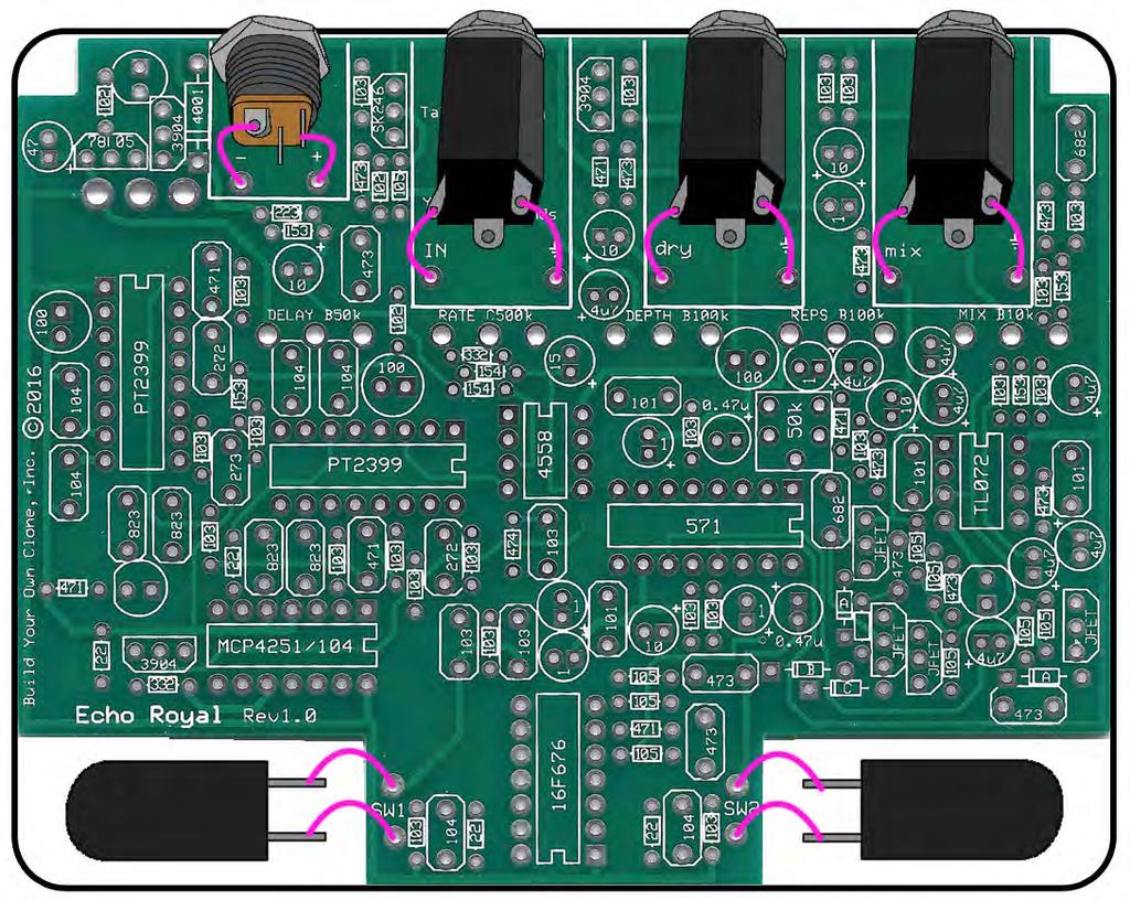
23 Step 7: Connect the TIP (negative) terminal of the DC adapter jack to the eyelet on the PCB labeled -. Connect the SLEEVE of the DC adapter jack to the eyelet on the PCB labeled + farthest to the right. Also connect the enclosed audio jacks to the PCB. The SLEEVE connection will go into the ground spots, and the TIP connection will connect to the in, dry, and mix eyelets as shown below.
24

25 Operating Overview Blend: Controls the dry to delay ratio. Repeats: Controls the amount of repeats in the delay. Depth: Depth control for the modulation. Rate: Rate control for the modulation Delay: Sets the delay time. Tap Multiplier: Sets the tap to delay time ratio. Quarter note = 1 echo per tap; dotted eighth note = 1.5 echoes per tap; eighth note = 2 echoes per tap; triplets = 3 echoes per tap; 16 th notes = 4 echoes per tap Bypass/Trails: Turns the effect on. Press and hold for 3 seconds to switch between trails and normal bypass modes. Tap Tempo: tap at least twice to set delay time. Press and hold for 2 seconds to switch back to delay time knob. NOTE: You do not need to do this to use the delay time knob. It will automatically switch back when it senses that you have turned the delay time knob. Power supply: 2.1mm negative tip Current Draw: 80mA Input Impedance: 1M Ohm Output Impedance: 47k Ohm

26 Back-side PCB Photo
27
28 For hi-res schematic visit Please visit For any technical support Copyright 2016 BYOC, Inc.
Build Your Own Clone Crown Jewel Kit Instructions
 Build Your Own Clone Crown Jewel Kit Instructions Warranty: BYOC, Inc. guarantees that your kit will be complete and that all parts and components will arrive as described, functioning and free of defect.
Build Your Own Clone Mouse Kit Instructions
 Build Your Own Clone Mouse Kit Instructions Warranty: BYOC, Inc. guarantees that your kit will be complete and that all parts and components will arrive as described, functioning and free of defect. Soldering,
Build Your Own Clone Li l Echo Kit Instructions
 Build Your Own Clone Li l Echo Kit Instructions Warranty: BYOC, Inc. guarantees that your kit will be complete and that all parts and components will arrive as described, functioning and free of defect.
Build Your Own Clone Li l Reverb Kit Instructions
 Build Your Own Clone Li l Reverb Kit Instructions Warranty: BYOC, Inc. guarantees that your kit will be complete and that all parts and components will arrive as described, functioning and free of defect.
Build Your Own Clone Green Pony Kit Instructions
 Build Your Own Clone Green Pony Kit Instructions Warranty: BYOC, Inc. guarantees that your kit will be complete and that all parts and components will arrive as described, functioning and free of defect.
Build Your Own Clone Silver Pony 2 Kit Instructions
 Build Your Own Clone Silver Pony 2 Kit Instructions Warranty: BYOC, Inc. guarantees that your kit will be complete and that all parts and components will arrive as described, functioning and free of defect.
Build Your Own Clone B.G. Fuzz Kit Instructions
 Build Your Own Clone B.G. Fuzz Kit Instructions Warranty: BYOC, Inc. guarantees that your kit will be complete and that all parts and components will arrive as described, functioning and free of defect.
Build Your Own Clone Li l Beaver (Ram s Head) Kit Instructions
 Kit Instructions") Build Your Own Clone Li l Beaver (Ram s Head) Kit Instructions Warranty: BYOC, Inc. guarantees that your kit will be complete and that all parts and components will arrive as described, functioning and
Build Your Own Clone Li l Beaver (Ram s Head) Kit Instructions Warranty: BYOC, Inc. guarantees that your kit will be complete and that all parts and components will arrive as described, functioning and
Build Your Own Clone 27V Boost Kit Instructions
 Build Your Own Clone 27V Boost Kit Instructions Warranty: BYOC, Inc. guarantees that your kit will be complete and that all parts and components will arrive as described, functioning and free of defect.
Build Your Own Clone Li l Analog Chorus Kit Instructions
 Build Your Own Clone Li l Analog Chorus Kit Instructions Warranty: BYOC, Inc. guarantees that your kit will be complete and that all parts and components will arrive as described, functioning and free
Build Your Own Clone The Swede Kit Instructions
 Build Your Own Clone The Swede Kit Instructions Warranty: BYOC, Inc. guarantees that your kit will be complete and that all parts and components will arrive as described, functioning and free of defect.
Build Your Own Clone Kuzco Jr. Kit Instructions
 Build Your Own Clone Kuzco Jr. Kit Instructions Warranty: BYOC, Inc. guarantees that your kit will be complete and that all parts and components will arrive as described, functioning and free of defect.
Build Your Own Clone Li l Comp Kit Instructions
 Build Your Own Clone Li l Comp Kit Instructions Warranty: BYOC, Inc. guarantees that your kit will be complete and that all parts and components will arrive as described, functioning and free of defect.
Build Your Own Clone Classic Phaser Kit Instructions
 Build Your Own Clone Classic Phaser Kit Instructions Warranty: BYOC, Inc. guarantees that your kit will be complete and that all parts and components will arrive as described, functioning and free of defect.
Build Your Own Clone Li l Pony Kit Instructions
 Build Your Own Clone Li l Pony Kit Instructions Warranty: BYOC, Inc. guarantees that your kit will be complete and that all parts and components will arrive as described, functioning and free of defect.
Build Your Own Clone Silver Pony Kit Instructions
 Build Your Own Clone Silver Pony Kit Instructions Warranty: BYOC, Inc. guarantees that your kit will be complete and that all parts and components will arrive as described, functioning and free of defect.
Build Your Own Clone Li l Beaver (Triangle Version) Kit Instructions
 Kit Instructions") Build Your Own Clone Li l Beaver (Triangle Version) Kit Instructions Warranty: BYOC, Inc. guarantees that your kit will be complete and that all parts and components will arrive as described, functioning
Build Your Own Clone Li l Beaver (Triangle Version) Kit Instructions Warranty: BYOC, Inc. guarantees that your kit will be complete and that all parts and components will arrive as described, functioning
Build Your Own Clone Analog Chorus Kit Instructions
 Build Your Own Clone Analog Chorus Kit Instructions Warranty: BYOC, Inc. guarantees that your kit will be complete and that all parts and components will arrive as described, functioning and free of defect.
Build Your Own Clone Spring Reverb Kit Instructions
 Build Your Own Clone Spring Reverb Kit Instructions Warranty: BYOC, Inc. guarantees that your kit will be complete and that all parts and components will arrive as described, functioning and free of defect.
Build Your Own Clone Chancellor Kit Instructions
 Build Your Own Clone Chancellor Kit Instructions Warranty: BYOC, Inc. guarantees that your kit will be complete and that all parts and components will arrive as described, functioning and free of defect.
Build Your Own Clone Parametric Multi-Band Compressor Kit Instructions
 Build Your Own Clone Parametric Multi-Band Compressor Kit Instructions Warranty: BYOC, Inc. guarantees that your kit will be complete and that all parts and components will arrive as described, functioning
Build Your Own Clone Analog Vibrato Kit Instructions
 Build Your Own Clone Analog Vibrato Kit Instructions Warranty: BYOC, Inc. guarantees that your kit will be complete and that all parts and components will arrive as described, functioning and free of defect.
Build Your Own Clone Mega Chorus & Vibrato Kit Instructions
 Build Your Own Clone Mega Chorus & Vibrato Kit Instructions Warranty: BYOC, Inc. guarantees that your kit will be complete and that all parts and components will arrive as described, functioning and free
Build Your Own Clone Tremolo Kit Instructions
 Build Your Own Clone Tremolo Kit Instructions Warranty: BYOC, LLC guarantees that your kit will be complete and that all parts and components will arrive as described, functioning and free of defect. Soldering,
Build Your Own Clone Classic Overdrive Kit Instructions
 Build Your Own Clone Classic Overdrive Kit Instructions Warranty: BYOC, LLC guarantees that your kit will be complete and that all parts and components will arrive as described, functioning and free of
Build Your Own Clone Reverb Kit Instructions
 Build Your Own Clone Reverb Kit Instructions Warranty: BYOC, LLC guarantees that your kit will be complete and that all parts and components will arrive as described, functioning and free of defect. Soldering,
Build Your Own Clone British Blues Overdrive Kit Instructions
 Build Your Own Clone British Blues Overdrive Kit Instructions Warranty: BYOC, LLC guarantees that your kit will be complete and that all parts and components will arrive as described, functioning and free
Build Your Own Clone Divided Octave Kit Instructions
 Build Your Own Clone Divided Octave Kit Instructions Warranty: BYOC, Inc. guarantees that your kit will be complete and that all parts and components will arrive as described, functioning and free of defect.
BYOC Vibrato Kit Instructions BA662A version
 BYOC Vibrato Kit Instructions BA662A version Please read these instructions very thoroughly before building even if you are an experience builder. Because of the layout, there is a certain order which
BYOC Analog Delay Kit Instructions
 BYOC Analog Delay Kit Instructions Please read through the instructions completely before beginning this project. This is one of our most difficult kits and it is a little different than other BYOC kits,
BYOC Vibrato Kit Instructions BA6110 version
 BYOC Vibrato Kit Instructions BA6110 version Please read these instructions very thoroughly before building even if you are an experience builder. Because of the
Guitarpedalkits.com Overdrive Pedal Build Instructions
 Page 1 Guitarpedalkits.com Overdrive Pedal Build Instructions Follow the instructions in this guide to build your very own DIY overdrive pedal from GuitarPedalKits.com. If you re a first time builder,
Value Location Qty Potentiometers C1M Distortion 1 A10k Volume 1. Footswitch 3PDT SW1 1. Jacks 1/4 Mono 2 DC Power 1
 Distortion BUILD INSTRUCTIONS Thank you for your purchase of our Distortion+ kit! We have completely redesigned our entire line of kits to be the most user friendly, while still maintaining their same
Value Location Qty Transistors 2N5485 Q1, Q2, 4 Q3, Q4 2N5087 Q5 1. Trim Pots 250k VTRIM 1. Potentiometers C500k Speed 1. Toggle Switch On/On Vibe 1
 P-90 BUILD INSTRUCTIONS Thank you for your purchase of our P-90 kit! We have completely redesigned our entire line of kits to be the most user friendly, while still maintaining their same great sound!
Mono Amplifier. LM386 Headphone Amp
 Mono Amplifier LM386 Headphone Amp Layout On/Off Switch - cuts power to the circuit Mono Input Jack: use either L or R or solder together Schematic Step 1 - Parts List 1.) R1-10ohm Resistor - Brown Black
GCI BRUTALIST JR. BUILD GUIDE
 GCI BRUTALIST JR. BUILD GUIDE The Brutalist Jr. is the DIY little brother to the GCI Brutalist, a high powered distortion pedal loosely based on the Providence Stampede SDT-1. It runs on 9v DC power or
THE STEP LADDER (K-978)
") THE STEP LADDER (K-978) Footswitch True-bypass = 0 db OUTPUT INPUT Ground shunt switching on the input jack keeps the amp quiet when unplugged from the Step Ladder. Attenuator Pot Full clockwise = 0 db
THE STEP LADDER (K-978) Footswitch True-bypass = 0 db OUTPUT INPUT Ground shunt switching on the input jack keeps the amp quiet when unplugged from the Step Ladder. Attenuator Pot Full clockwise = 0 db
Jour de FET Mounting instructions.
 Jour de FET Mounting instructions. Summary Important notice. What's in the kit? What you'll need. Soldering on the pcb. Wiring the pedal. Test the board. Debugging chapter. Hacks!!! 3 4 4 3 5 6 Copyright
Building the Toothpick Audio CW Filter
 Building the Toothpick Audio CW Filter Introduction The toothpick is a simple variable bandpass audio filter designed to compliment the Splinter QRPp Trans-Receiver. The filter also contains an audio amplifier
Starving Student II. Starving Student II. SS2 guide. Written By: 6L guides.diyaudio.com/ Page 1 of 24
 SS2 guide Written By: 6L6 2019 guides.diyaudio.com/ Page 1 of 24 INTRODUCTION This is a build guide for the hybrid headphone/pre-amplifier. You can buy a kit at the SSII product listing on the diyaudio
Assembly Instructions
 Assembly Instructions For the SSQ-2F 3.1 MHz Rife Controller Board Kit v1.41 Manual v1.00 2012 by Ralph Hartwell Spectrotek Services GENERAL ASSEMBLY INSTRUCTIONS Arrange for a clean work surface with
Pingable Envelope Generator
 Pingable Envelope Generator Kit Builder's Guide for PCB v1.0.3 4mspedals.com PEG This guide is for building a Pingable Envelope Generator (PEG), which is an intermediate-level kit. You should be confident
4ms SCM Breakout. Kit Builder's Guide for PCB v2.1 4mspedals.com
 4ms SCM Breakout Kit Builder's Guide for PCB v2.1 4mspedals.com Shuffling Clock Multiplier Breakout This guide is for building a Shuffling Clock Multiplier Breakout module (SCMBO) version 2.1 from the
Build Guide CascadiA. GeFet Preamp
 Build Guide CascadiA GeFet Preamp Disclaimery stuff: This project is meant to be assembled by fellow DIYers from the Madbean forum and should only be used for the forces of good. Any other uses prohibited
Glue Fuzz Mounting instructions.
 Glue Fuzz Mounting instructions. Index Important notice. 2 What's in the kit? 3 What you'll need. 4 Soldering on the pcb. 4 Wiring the pedal. 11 Test the board. 12 Debugging chapter. 13 Copyright Zorg
STEP 0 Prepare the Materials.
 How to Build a Germanium Fuzz Guitar Effect. This document will guide you to build and test your Germanium Fuzz guitar pedal. With all the materials on hand, it takes around 2-4 hours to build it. Try
NEW WAVE CV GENERATOR Build Document last updated september 2017 for PCB version 1.0
 NEW WAVE CV GENERATOR Build Document last updated september 2017 for PCB version 1.0 The New Wave is a Control Voltage Generator. It has two LFO's (low frequency oscillators) and four different output
Designed to send specific MIDI information upon each press. Ultra-low current requirement means a single coin cell will last years
 PedalSync MIDI Data Module Key Features Discrete MIDI Data delivery in a compact design Designed to send specific MIDI information upon each press Ultra-low current requirement means a single coin cell
DELUXE MEMORY MAN w/ TAP TEMPO TAP TEMPO ANALOG DELAY with FX LOOP, MODULATION and EXPRESSION PEDAL CONTROL
 DELUXE MEMORY MAN w/ TAP TEMPO TAP TEMPO ANALOG DELAY with FX LOOP, MODULATION and EXPRESSION PEDAL CONTROL Congratulations on your purchase of the Electro-Harmonix Deluxe Memory Man w/ Tap Tempo (DMMTT).
How to build a Cracklebox. Red Wierenga Brooklyn College Center for Computer Music October 13, 2015
 How to build a Cracklebox Red Wierenga Brooklyn College Center for Computer Music October 13, 2015 What s a Cracklebox? What s a Cracklebox? The Cracklebox was developed by Michel Waisvisz and others at
TS500 Assembly guide. Soldering. TS500 Assembly guide Main PCB 1. Diodes. Document revision 1.2 Last modification : 17/12/16
 TS500 Assembly guide Safety warning The kits are main powered and use potentially lethal voltages. Under no circumstance should someone undertake the realisation of a kit unless he has full knowledge about
Penrose Quantizer Assembly Guide
 Penrose Quantizer Assembly Guide Schematic and BOM The schematic can be found here: www.sonic-potions.com/public/penrosequantizerschematic.pdf The BOM is available at google docs: Link to BOM Prepare the
LDB-1 Kit Instructions Page 1 of 8
 LDB-1 Kit Instructions Page 1 of 8 Important Information Congratulations and thank you for your purchase of the LDB-1 Little Drummer Boy Analog Drum Machine Kit! Before you start, please read the enclosed
Dig Dug madbeanpedals FX Type: Sequencer W x 3.25 H
 Dig Dug2 2015 madbeanpedals FX Type: Sequencer 4.15 W x 3.25 H B.O.M. Resistors Caps Diodes R1 1M C1 100n D1 1N5817 R2 1M C2 220n D2 - D4 1n914 R3 10k C3 15n LED1-8 3mm Red R4 330k C4 2n2 PATT 3mm Red
Axis Fuzz Kit Building Manual
 Axis Fuzz Kit Building Manual Effect Pedal Kits: Axis Fuzz The Axis Fuzz Kit is based in the Roger Mayer Axis Fuzz, the effect pedal responsible for Jimi Hendrix sound in Axis Bold As Love. What else is
Assembly and User Guide
 Assembly and User Guide AtariPunkr is an adjustable stepped tone generator. AtariPunkr provides hours of fun everyone! Powered by: 9V Battery Outputs: Mylar Speaker (Included) Stereo Output (3.5mm Jack)
THE THUNDERDRIVE (K-950)
") THE THUNDERDRIVE (K-950) OUTPUT DISTORTION Unplug when not in use to save battery life. TO AMP IN The Thunderdrive Modkitsdiy.com FROM GUITAR OUT Use these instructions to learn: How to build an effects
THE THUNDERDRIVE (K-950) OUTPUT DISTORTION Unplug when not in use to save battery life. TO AMP IN The Thunderdrive Modkitsdiy.com FROM GUITAR OUT Use these instructions to learn: How to build an effects
Bill of Materials: PWM Stepper Motor Driver PART NO
 PWM Stepper Motor Driver PART NO. 2183816 Control a stepper motor using this circuit and a servo PWM signal from an R/C controller, arduino, or microcontroller. Onboard circuitry limits winding current,
BUILD YOUR OWN. Fuzz Face SUPER-FREQ.COM
 BUILD YOUR OWN Fuzz Face SUPER-FREQ.COM CHAPTER 1 The Fuzz Face By Mitchell Hudson of super-freq.com, in conjunction with Joe Gore of tonefiend.com. Build your own vintage Fuzz Face! Create a vintage-style
THE RING RESONATOR (K-975)
") THE RING RESONATOR (K-975) OUTPUT BOOST The Ring Resonator An Octave Up Fuzz Modkitsdiy.com 9 VDC CENTER (-) ADAPTER TO AMP IN FROM GUITAR OUT Unplug when not in use to save battery life. Use these instructions
THE RING RESONATOR (K-975) OUTPUT BOOST The Ring Resonator An Octave Up Fuzz Modkitsdiy.com 9 VDC CENTER (-) ADAPTER TO AMP IN FROM GUITAR OUT Unplug when not in use to save battery life. Use these instructions
MONO AMPLIFIER KIT ESSENTIAL INFORMATION. Version 3.0 CREATE YOUR OWN SPEAKER DOCK WITH THIS
 ESSENTIAL INFORMATION BUILD INSTRUCTIONS CHECKING YOUR PCB & FAULT-FINDING MECHANICAL DETAILS HOW THE KIT WORKS CREATE YOUR OWN SPEAKER DOCK WITH THIS MONO AMPLIFIER KIT Version 3.0 Build Instructions
ABC V1.0 ASSEMBLY IMPORTANT!
 ABC V1.0 ASSEMBLY Before starting this kit, prepare the following tools: Soldering iron (15-20W will do), flush cutters, no.2 hex screwdriver or allen key and phillips screwdriver. Also briefly go through
PAT-4 POWER SUPPLY ASSEMBLY MANUAL Rev B Version
 PAT-4 POWER SUPPLY ASSEMBLY MANUAL Rev B Version 2013 AkitikA, LLC All rights reserved Revision Bp01 November 3, 2013 Page 1 of 16 Table of Contents Table of Contents... 2 Table of Figures... 2 Section
Rangemaster Treble Booster Kit Building Manual
 Rangemaster Treble Booster Kit Building Manual Effect Pedal Kits: Rangemaster Treble Booster The Dallas Rangemaster is the most famous treble booster effect pedal, and it was the first pedal of its kind.
THE TRILL TREMOLO (K-960)
") THE TRILL TREMOLO (K-60) DEPTH SPEED The Trill Tremolo Modkitsdiy.com Unplug when not in use to save battery life. TO AMP IN FROM GUITAR OUT Use these instructions to learn: How to build an effects pedal
THE TRILL TREMOLO (K-60) DEPTH SPEED The Trill Tremolo Modkitsdiy.com Unplug when not in use to save battery life. TO AMP IN FROM GUITAR OUT Use these instructions to learn: How to build an effects pedal
THE AGGRESSOR (K-995)
") THE AGGRESSOR (K-99) TONE VOLUME DISTORTION MID-SHIFT SWITCH LED The Aggressor Distortion Pedal Modkitsdiy.com 9 VDC CENTER (-) ADAPTER TO AMP IN FROM GUITAR OUT Unplug when not in use to save battery
THE AGGRESSOR (K-99) TONE VOLUME DISTORTION MID-SHIFT SWITCH LED The Aggressor Distortion Pedal Modkitsdiy.com 9 VDC CENTER (-) ADAPTER TO AMP IN FROM GUITAR OUT Unplug when not in use to save battery
LunarBlast v1.0. Optical Tremolo. Description:
 LunarBlast v1.0 Optical Tremolo Description: Based on the venerable DIY Tremulus Lune classic circuit, www.madbean.com forum member CultureJam created this awesome sounding tremolo dubbed the Shoot the
Ultimatum Fuzz. The Ultimate experience in vintage-style octave-up fuzz
 Ultimatum Fuzz The Ultimate experience in vintage-style octave-up fuzz Contents of this document are 2015 Pedal Parts Ltd. No reproduction permitted without the express written permission of Pedal Parts
LA502 Assembly guide Main PCB Resistors - (2)
") LA502 Assembly guide Safety warning The kits are main powered and use potentially lethal voltages. Under no circumstance should someone undertake the realisation of a kit unless he has full knowledge about
LA502 Assembly guide Safety warning The kits are main powered and use potentially lethal voltages. Under no circumstance should someone undertake the realisation of a kit unless he has full knowledge about
Chunky Cheese Build Guide Rev
 Chunky Cheese Build Guide Rev. 2008-08-04 The Chunky Cheese is a slightly-modified version of the discontinued Big Cheese fuzz pedal. Table of Contents Table of Contents... 1 PCB Layout... 2 Parts List...
Easy Transmitter. Support ETX_REV5_Manual V2.7 Revised
 Easy Transmitter Introduction The Easy Transmitter kit from qrpkits.com provides a basic, crystal controlled transmitter with VXO tuning to provide a small tuning range around the crystal frequency. It
SDR Cube Transceiver Online Assembly Guide
 SDR Cube Transceiver Online Assembly Guide Detailed construction notes for building and testing each of the SDR Cube kit modules Home Bill of Materials I/O Board Controls Board DSP Board Softrock SR-Base
Electric Druid 4 second Digital Delay Project
 Electric Druid 4 second Digital Delay Project Overview! 2 Build Instructions! 2 Populate the PCB! 2 Resistors! 2 Cup of tea and soldering check! 3 Power protection diode! 4 Ground link wire! 4 IC sockets!
QRPGuys Michigan Mighty Might Plus 40M Transmitter
 QRPGuys Michigan Mighty Might Plus 40M Transmitter First, familiarize yourself with the parts and check for all the components. If a part is missing, please contact us and we will send one. You must use
Cricket 80a Assembly Manual v Copyright David Cripe NM0S The 4 State QRP Group
 Cricket 80a Assembly Manual v. 1.0 Copyright 2017 David Cripe NM0S The 4 State QRP Group Introduction Thank you for purchasing a CRICKET 80a Transceiver. We hope you will enjoy building it and find it
LED Field Strength Indicator Kit
 LED Field Strength Indicator Kit Description The Field Strength Indicator kit from Qrpkits.com provides a visual way to monitor RF fields through the brightness of an LED. It will respond to RF fields
Electric Druid Flangelicious Flanger Project
 Electric Druid Flangelicious Flanger Project (Using either 4KNOBFLANGE or MULTIFLANGE chips) Overview! 2 Build Instructions! 2 Populate the PCB! 2 1N4148 Diodes! 2 Resistors! 2 Cup of tea and soldering
Code Practice Oscillator (CPO) For kit building instructions turn to Page 3.
 For kit building instructions turn to Page 3.") Code Practice Oscillator (CPO) For kit building instructions turn to Page 3. Overview Many thanks for your purchase of this code practice oscillator or CPO, this guide is intended to allow you to quickly
Code Practice Oscillator (CPO) For kit building instructions turn to Page 3. Overview Many thanks for your purchase of this code practice oscillator or CPO, this guide is intended to allow you to quickly
Manual Version July 2007
 Manual Version 1.2 - July 2007 Page 1 Table of Contents Section1: M3 Phono Board Build...3 Phono Board Parts List...3 Preparation...4 Fitting the Valve Bases...6 Installing the Resistors...7 Starting the
Building The DC Beeper from Jackson Harbor Press A Morse code voltmeter / DC switch
 Building The DC Beeper and from Jackson Harbor Press Operating A Morse code voltmeter / DC switch The DC Beeper kit is a combination of a Morse code voltmeter with 20 mv resolution and a DC switch. The
KASTLE v1.5 - Assembly Guide
 last update: 14. 12. 2017 KASTLE v1.5 - Assembly Guide bastl-instruments.com INTRODUCTION Welcome to the assembly guide for the Kastle kit - mini modular synthesizer. It is suitable for beginners. It is
TV Remote. Discover Engineering. Youth Handouts
 Discover Engineering Youth Handouts Electronic Component Guide Component Symbol Notes Amplifier chip 1 8 2 7 3 6 4 5 Capacitor LED The amplifier chip (labeled LM 386) has 8 legs, or pins. Each pin connects
DIODE / TRANSISTOR TESTER KIT
 DIODE / TRANSISTOR TESTER KIT MODEL DT-100K Assembly and Instruction Manual Elenco Electronics, Inc. Copyright 1988 Elenco Electronics, Inc. Revised 2002 REV-K 753110 DT-100 PARTS LIST If you are a student,
BMC052. Chordizer Last updated
 BMC052. Chordizer Last updated 8-27-2017 If you have any questions, or need help trouble shooting, please e-mail Michael@Bartonmusicalcircuits.com I Overview/Controls/Inputs/Outputs II Schematic III Construction
Step by Step Building PJ meter ARDF Receiver Kit. CRKITS.COM August 5, 2013
 Step by Step Building PJ-80 80-meter ARDF Receiver Kit CRKITS.COM August 5, 2013 What is ARDF? ARDF is the abbreviation of Amateur Radio Direction Finding, or so called Fox Hunting. If you are looking
VC Divider Assembly manual
 1 VC Divider Assembly manual Thank you for your purchase of the SSSR Labs VC Divider DIY Kit! This manual will help you assemble the VC Divider quickly and easily. Follow the instructions! As you may know,
How To Tame A Wild Mouse
 How To Tame A Wild Mouse By Steve Daniels, President, Small Bear Electronics LLC What's A Wild Mouse? This Wild Mouse is an active tone boost--an amplifier that is tuned with a filter so that it boosts
Multiwave. Guitar Synthesizer. Build Document last updated november 2018 Version
 Multiwave Guitar Synthesizer Build Document last updated november 2018 Version 1.0 2018 The Multiwave is a guitar controlled oscillator with 3 different waveshapes: saw, triangle and square. Combined,
MP573 Assembly guide. Soldering. MP573 Assembly guide PCB split PCB split. Document revision 2.2 Last modification : 22/08/17
 MP573 Assembly guide Safety warning The kits are main powered and use potentially lethal voltages. Under no circumstance should someone undertake the realisation of a kit unless he has full knowledge about
Pacific Antenna Wall Wart Tamer 2.0 Kit
 Pacific Antenna Wall Wart Tamer 2.0 Kit Description The Wall Wart Tamer lets you utilize those surplus computer and wall pack power supplies as a clean, adjustable voltage, DC power source for radios and
Find a place where you can work through completion, without disturbing your
 Scan by Manual Manor ARIES SYSTEM 300 MUSIC SYNTHESIZER Page I of 4 MODULE AR-334 SEQUENCER ASSEMBLY INSTRUCTIONS It is recommended that you do the following before you proceed: Find a place where you
Specimen Products Single Ended Stereo Amp Instruction Book
 Specimen Products Single Ended Stereo Amp Instruction Book Specimen tube amplifier designs are informed by decades of servicing and building musical instrument amps. As a result of being subjected to the
Slow Century Build Guide
 Slow Century Build Guide In 1986, Michael Soldano founded an amp company in Los Angeles. Known for high-gain designs, Soldano has produced a number of amps that have been critical successes with a huge
Foxhunt Offset Attenuator. Parts List:
 When your closing in on the fox you may find the signals to be so strong that you can no longer find a peak or null with your antenna. Sometimes the signal is so strong that the RF will leak straight into
FM RADIO KIT ESSENTIAL INFORMATION. Version 2.0 GET IN TUNE WITH THIS
 ESSENTIAL INFORMATION BUILD INSTRUCTIONS CHECKING YOUR PCB & FAULT-FINDING MECHANICAL DETAILS HOW THE KIT WORKS GET IN TUNE WITH THIS FM RADIO KIT Version 2.0 Build Instructions Before you start, take
Read This Page First
 Read This Page First If you are reading this you know the manuals are always available at QRPKITS.com. This is version 8.0 of the manual dated 4/27/2016. There is no need to print out the whole assembly
DIODE / TRANSISTOR TESTER KIT
 DIODE / TRANSISTOR TESTER KIT MODEL DT-100K 99 Washington Street Melrose, MA 02176 Phone 781-665-1400 Toll Free 1-800-517-8431 Visit us at www.testequipmentdepot.com Assembly and Instruction Manual Elenco
MICROGRANNY v2.1 - Assembly Guide
 last update: 9. 5. 2017 MICROGRANNY v2.1 - Assembly Guide bastl-instruments.com INTRODUCTION Welcome to the assembly guide for the MicroGranny kit. MicroGranny is a monophonic granular sampler by Bastl
Stage Fright 2015 edition FX TYPE: Phaser Based on the Maestro Phaser 2015 madbeanpedals
 Stage Fright 2015 edition FX TYPE: Phaser Based on the Maestro Phaser 2015 madbeanpedals 2.3" W x 3.45" H Previous Version: http://www.madbeanpedals.com/stagefright/stagefright.zip Terms of Use: You are
BMC017. 2LFOSH Last updated I Features II Schematics III Construction
 BMC017. 2LFOSH Last updated 12-3-2013 I Features II Schematics III Construction I. Features The 2LFOSH module is a combination of three different modules on one board, designed to be easy to be easy to