TWIN PEAKS TREMOLO. Build Guide for v3.1
|
|
|
- Gervase Harrison
- 5 years ago
- Views:
Transcription

1 TWIN PEAKS TREMOLO Build Guide for v3.1 Revision 3.1 David Rolo 2017
2
3
4 Reference Quantity Value Description Switches Multiplier 1 1 pole 6 pos. rotary switch Shape 1 1 pole 8 pos. rotary switch Trem Type 1 2 pole 4 pos. rotary switch Tap Switch 1 Normally open Momentary Switch single pole NO Capacitors C18, C p Ceramic Capacitor C5, C p Ceramic Capacitor C4 1 4n7 Film Capacitor C3 1 6n8 Film Capacitor C n Film Capacitor C10, C12, C13, C16, C21, C22, C23, C24, C25, C n Ceramic Capacitor C n Ceramic Capacitor C9 1 1u Film Capacitor C6, C7 2 10u Non Polar Electrolytic Capacitor C u Electrolytic Capacitor C11, C14, C u Electrolytic Capacitor IC's U1 1 TL074 OpAmp U2 1 LM358 OpAmp U3 1 TAPLFO Microchip Diodes D1 1 1N5819, 1N5817 Schottky Diode D2 1 1n4001 Diode, optional, see notes Tap Led 1 LED Light Emitting Diode LED1 2 LED with max. 2V fwd voltage Light Emitting Diode Misc T1, T2 2 78L05 Fixed Voltage Reg. XTAL 1 20 Mhz Crystal OPTO1, OPTO2 2 VTL5C1 or self rolled LED/LDR Optocoupler Resistors R13, R14, R Resistor R47, R Resistor R21, R22, R23, R24, R25 5 1k Resistor R9 1 3k3 Resistor R32, R33, R41 3 5k1 Resistor R18, R19, R20, R27, R28, R29, R30, R31, R34, 20 10k Resistor R35, R36, R37, R38, R39, R40, R42, R43, R44,R45, R46 R3, R4, R5, R6 4 15k Resistor R11, R12, R16, R k Resistor R k Resistor R7, R8 2 56k Resistor R1, R10, R2 3 1M Resistor Potentiometers Tone 1 10k lin Potentiometer Rate 1 10k lin Potentiometer Depth 1 10k lin Potentiometer Symmetry 1 10k lin Potentiometer Volume 1 50k Trimmer Offset 1 20k Trimmer Bass 1 20k Trimmer Treble 1 20k Trimmer


5 The pots best suited are Alpha 16mm Right-angle PCB mount Pots: And the mini rotary switches should be this type: However, the PCB was laid so you could use a potentiometer instead of the 1p6t and 1p8t rotary switches, which are a little harder to find. If you go with that solution, use 10k lin pots like the other ones in the parts list. Use a 3k6 for R26 instead of 24k and do NOT populate these resistors: from R27 to R41. Of course you can use other parts and not mount them on the PCB. Then you will probably need a bigger enclosure.
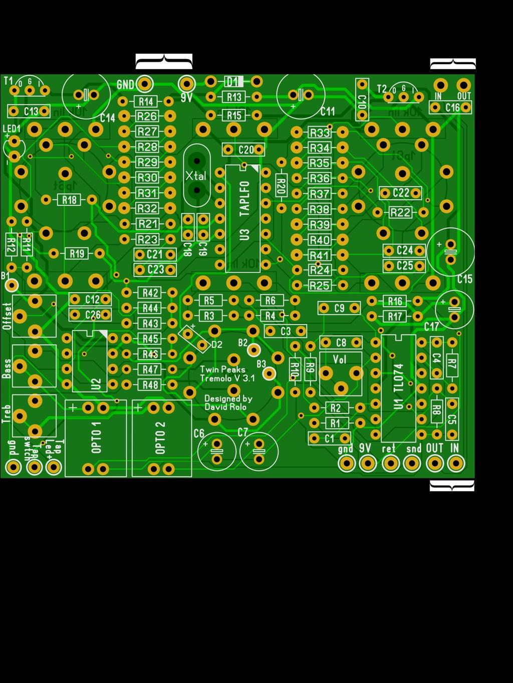
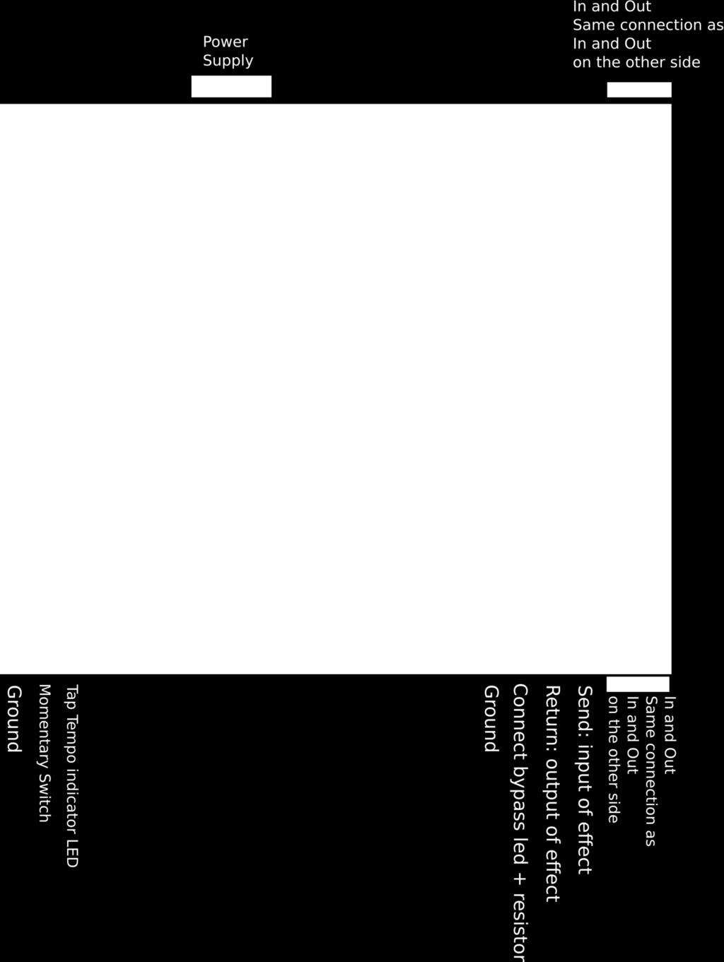
6 Notes: Use sockets for the IC s, at least for the TAPLFO Populate the boards with all parts, starting with the smallest to the tallest. Solder in the pots and rotary switch last. D2 can actually be bridged, unless you feel that the non-modulated parts in the Bass only and treble only modes are too loud compared to the modulated signal. R19 is the current limiting resistor for the Tempo indicating LED. The indicated value of 10k is what I am using with white super-bright LED s. Choose the value that will be best for your particular LED. I would recommend a super-bright as they will draw less current and reduce the chances of inducing ticking. C26 is used to smooth out the sharp corners of the LFO signal and remove some spikes that can produce audible clicks especially with sharper edged wave shapes. You might not necessarily need it. It depends on your particular Optocoupler and whether you like the signal to be chopped real hard or not. I suggest socketing that cap, trying without it first and then start with a low value like 20n until you find a value that removes the tick but does not round off the square wave too much. C3 and C4 define the High Pass and Low pass cut off frequency. If my calculations are right, with the values indicated in this document, the Low pass cuts at Hz and the Hi pass at Hz. You can of course experiment with other values. LED1 is there to increase the output of the voltage regulator (5V + the Forward voltage of the LED). Try to find a LED with no more than 2V FWD voltage to make sure the voltage regulator still has enough drop out voltage to operate correctly. The IN and OUT pads on the top and bottom of the PCB s are just to route the input and output from your jacks. You don t have to necessarily use them, I just find it convenient. C6 and C7, for safety s sake these should be bipolar/non polar electrolytics. Though on my unit I am using regular caps for a while and nothing happened (yet)
7
8 Biasing: 1) Turn the DEPTH pot fully counterclockwise, SYMMETRY and TONE in middle position 2) Start with the Offset, Bass and Treble trimmers fully counterclockwise Leave the volume trimmer at midpoint for now. 3) Start by measuring the supply voltage at measure point B1 4) Now measure the voltage at B2 and B3 and adjust the Offset trimmer until you get half of the voltage you measured on B1. This action will center the LFO signal (originally 0-5V) around the bias voltage of U2. 5) Now adjust the Bass and Treble trimmers to have a good balance between bass and treble. As you turn clockwise, the optocoupler gets more current and the signal gets louder. But increasing the current also increases the chance of getting audible clicks, especially with sharp wave shapes. So it s best to be conservative and compensate for the volume with the volume trimmer. 6) Adjust the volume trim pot T1 to have the same level between effect OFF and effect ON (or any level you like). That s it! Now trem away ;-)

9 Controls: Rotating from CCW to CW, the rotary switch selects the tremolo modes: Bass and treble modulated in phase (normal tremolo) Bass and treble modulated out of phase (Harmonic tremolo) Bass modulation only, with fix treble Treble modulation only, with fix bass Tone : adjusts the balance between the bass and treble portions. Turn it fully CCW and only the bass comes out. Turn it fully CW and you get only treble. In the middle you get both. If you turn down the depth completely you can use the tone knob as a sort of EQ Depth: Allows setting the depth of the modulation Rate: Sets the speed of the modulation Symmetry: Allows changing the ratio between the upper and lower wave of the LFO signal For example, when using the square wave, you can set whether the off or the on periods are the longest. This diagram shows the effect of the symmetry pot on some wave shapes: Source: Shape: This knob allows selecting one of the 8 available modulation wave shapes: Source:

10 Multiplier: allows to select the multiplier that will be applied to the tapped tempo Source:
11 This is a drill template I have been using but take your own measurements to make sure everything fits (before committing to drilling your box ;-)
Liquid Mercury Phaser. Build doc V2.0
 Liquid Mercury Phaser Build doc V2.0 David Rolo / December 2014 The build consists of 2 boards that were designed to fit in a BB enclosure with top mounted open jacks. PCB1 holds the pcb mounted pots and
Dig Dug madbeanpedals FX Type: Sequencer W x 3.25 H
 Dig Dug2 2015 madbeanpedals FX Type: Sequencer 4.15 W x 3.25 H B.O.M. Resistors Caps Diodes R1 1M C1 100n D1 1N5817 R2 1M C2 220n D2 - D4 1n914 R3 10k C3 15n LED1-8 3mm Red R4 330k C4 2n2 PATT 3mm Red
UK-electronic 2012/15 Manual for the Tap Tremolo Rev. 2.0 Based on TAPLFO from Tom Wiltshire (www.electricdruid.com)
") UK-electronic 2012/15 Manual for the Tap Tremolo Rev. 2.0 Based on TAPLFO from Tom Wiltshire (www.electricdruid.com) Page 1..2...Basics Page 3...short Circuit description Page 4...Bill of material Page
UK-electronic 2012/15 Manual for the Tap Tremolo Rev. 2.0 Based on TAPLFO from Tom Wiltshire (www.electricdruid.com) Page 1..2...Basics Page 3...short Circuit description Page 4...Bill of material Page
LunarBlast v1.0. Optical Tremolo. Description:
 LunarBlast v1.0 Optical Tremolo Description: Based on the venerable DIY Tremulus Lune classic circuit, www.madbean.com forum member CultureJam created this awesome sounding tremolo dubbed the Shoot the
Electric Druid Flangelicious Flanger Project
 Electric Druid Flangelicious Flanger Project (Using either 4KNOBFLANGE or MULTIFLANGE chips) Overview! 2 Build Instructions! 2 Populate the PCB! 2 1N4148 Diodes! 2 Resistors! 2 Cup of tea and soldering
Super Nova Distortion
 Super Nova Distortion The Super Nova is a reworking of the Marshall Guv'nor circuit. It uses the same gain structure as its parent design but is EQ'ed quite differently. The basic tone from the gain stages
Dirtbaby FX TYPE: Delay Based on the EHX DMM 2016 madbeanpedals
 Dirtbaby FX TYPE: Delay Based on the EHX DMM 2016 madbeanpedals 3.325 W x 2.325 H Terms of Use: You are free to use purchased circuit boards for both DIY and small commercial operations. You may not offer
Electric Druid 4 second Digital Delay Project
 Electric Druid 4 second Digital Delay Project Overview! 2 Build Instructions! 2 Populate the PCB! 2 Resistors! 2 Cup of tea and soldering check! 3 Power protection diode! 4 Ground link wire! 4 IC sockets!
PCB by 1776 Effects/JRM 2013 Circuit Design by Jon Patton
 Cardinal Tremolo PCB by 1776 Effects/JRM 2013 Circuit Design by Jon Patton The Cardinal Tremolo is a transistor and vactrol implementation of the Harmonic Tremolo. It resembles the harmonic tremolo from
DIY Function Generator XR2206
 DIY Function Generator XR2206 20Hz 100KHz http://radiohobbystore.com Components List: Resistors: R1, R2 1% Metal Film 5K1 R4 1% Metal Film 10K R5 1% Metal Film 3K R10 5% Carbon Film 10R R3, R9 Potentiometer
BMC052. Chordizer Last updated
 BMC052. Chordizer Last updated 8-27-2017 If you have any questions, or need help trouble shooting, please e-mail Michael@Bartonmusicalcircuits.com I Overview/Controls/Inputs/Outputs II Schematic III Construction
D Lay by GuitarPCB. We also carry the D'lay Tap Tempo board available separately in our SHOP. Not mandatory.
 D Lay by GuitarPCB Based on an Analog Style Delay but with added Delay time of up to 350-400ms, or slightly longer depending on quality of the PT2399 chip you use. Many months and trials went into perfecting
GCI BRUTALIST JR. BUILD GUIDE
 GCI BRUTALIST JR. BUILD GUIDE The Brutalist Jr. is the DIY little brother to the GCI Brutalist, a high powered distortion pedal loosely based on the Providence Stampede SDT-1. It runs on 9v DC power or
Read This Page First
 Read This Page First If you are reading this you know the manuals are always available at QRPKITS.com. This is version 8.0 of the manual dated 4/27/2016. There is no need to print out the whole assembly
BMC040. Dual Logic. Last updated
 BMC040. Dual Logic. Last updated 2-1-2016 If you have any questions, or need help trouble shooting, please e-mail Michael@Bartonmusicalcircuits.com I Overview/Features II Schematic III Construction A.Parts
Electric Druid Tap Tempo LFO
 Electric Druid Tap Tempo LFO Introduction 2 Features 3 Simple Tap Tempo control 3 Ability to synchronize LFO to external clocks 3 LFO range from 0.025Hz to above 50Hz 3 Sixteen output waveforms, in two
Cave Dweller 2015 edition FX Type: Delay 2015 madbeanpedals
 Cave Dweller 2015 edition FX Type: Delay 2015 madbeanpedals 1.3" W x 1.975" H (main board) Previous Version: http://www.madbeanpedals.com/projects/cavedweller/cavedweller_drill.zip Terms of Use: You are
BassAce - Midi Bass Synthesizer. BassAce Features
 Untitled Document BassAce - Midi Bass Synthesizer The BassAce is a small midi-synth based loosely on the TB303. It can be built many different ways. Depending on how it's configured it can be anything
Value Location Qty Potentiometers C1M Distortion 1 A10k Volume 1. Footswitch 3PDT SW1 1. Jacks 1/4 Mono 2 DC Power 1
 Distortion BUILD INSTRUCTIONS Thank you for your purchase of our Distortion+ kit! We have completely redesigned our entire line of kits to be the most user friendly, while still maintaining their same
Dual Digital Build Manual
 Dual Digital Build Manual Introduction This document is meant to aid you in assembling your Dual Digital Oscillator (DDO from now on). Some instructions may be a bit basic for advanced builders but I hope
TLN-428 Voltage Controlled State Variable Filter
 The Tellun Corporation TLN-428 Voltage Controlled State Variable Filter User Guide, Rev. 1.1 Scott Juskiw The Tellun Corporation scott@tellun.com TLN-428 User Guide Revision 1.1 March 16, 2003 Introduction
NEW WAVE CV GENERATOR Build Document last updated september 2017 for PCB version 1.0
 NEW WAVE CV GENERATOR Build Document last updated september 2017 for PCB version 1.0 The New Wave is a Control Voltage Generator. It has two LFO's (low frequency oscillators) and four different output
4-Pole Mission filter board
 4-Pole Mission filter board One board to rule them all This filter board is probably the most advanced 4-pole core for the Shruthi-system! It uses the same Pole-mixing technique introduced in the Oberheim
STEP 0 Prepare the Materials.
 How to Build a Germanium Fuzz Guitar Effect. This document will guide you to build and test your Germanium Fuzz guitar pedal. With all the materials on hand, it takes around 2-4 hours to build it. Try
CV Arpeggiator Rev 1. Last updated
 CV Arpeggiator Rev Last updated 6--20 The CV Arpeggiator is a modular synth project used for creating arpeggios of control voltage. It utilizes a custom programmed PIC 6F685 micro controller. It includes
The Tellun Corporation. TLN-442 Voltage Controlled Lowpass Filter. User Guide, Rev Scott Juskiw The Tellun Corporation
 The Tellun Corporation TLN-442 Voltage Controlled Lowpass Filter User Guide, Rev. 1.1 Scott Juskiw The Tellun Corporation scott@tellun.com TLN-442 User Guide Revision 1.1 March 15, 2003 Introduction The
Stage Fright 2015 edition FX TYPE: Phaser Based on the Maestro Phaser 2015 madbeanpedals
 Stage Fright 2015 edition FX TYPE: Phaser Based on the Maestro Phaser 2015 madbeanpedals 2.3" W x 3.45" H Previous Version: http://www.madbeanpedals.com/stagefright/stagefright.zip Terms of Use: You are
FX Type: Distortion 1.95 W x H Terms of Use: Slow Loris Slow Loris
 Slow Loris 2015 edition madbeanpedals FX Type: Distortion Based on the ProCo Rat Changes for the 2015 edition: Slight layout adjustments. No circuit changes. Previous version: http://www.madbeanpedals.com/projects/slowloris/docs/slowloris.zip
R*S Stereo Mixer V1.2
 R*S Stereo Mixer V1.2 The Random*Source Equal Power Stereo-Mixer is a voltage controlled stereo mixer / panner / VCA based on 4 high-end THAT2180 blackmer VCAs, designed to emulate the behavior of Serge
LA502 Assembly guide Main PCB Resistors - (2)
") LA502 Assembly guide Safety warning The kits are main powered and use potentially lethal voltages. Under no circumstance should someone undertake the realisation of a kit unless he has full knowledge about
LA502 Assembly guide Safety warning The kits are main powered and use potentially lethal voltages. Under no circumstance should someone undertake the realisation of a kit unless he has full knowledge about
Axis Fuzz Kit Building Manual
 Axis Fuzz Kit Building Manual Effect Pedal Kits: Axis Fuzz The Axis Fuzz Kit is based in the Roger Mayer Axis Fuzz, the effect pedal responsible for Jimi Hendrix sound in Axis Bold As Love. What else is
Value Location Qty Transistors 2N5485 Q1, Q2, 4 Q3, Q4 2N5087 Q5 1. Trim Pots 250k VTRIM 1. Potentiometers C500k Speed 1. Toggle Switch On/On Vibe 1
 P-90 BUILD INSTRUCTIONS Thank you for your purchase of our P-90 kit! We have completely redesigned our entire line of kits to be the most user friendly, while still maintaining their same great sound!
Multiwave. Guitar Synthesizer. Build Document last updated november 2018 Version
 Multiwave Guitar Synthesizer Build Document last updated november 2018 Version 1.0 2018 The Multiwave is a guitar controlled oscillator with 3 different waveshapes: saw, triangle and square. Combined,
Rangemaster Treble Booster Kit Building Manual
 Rangemaster Treble Booster Kit Building Manual Effect Pedal Kits: Rangemaster Treble Booster The Dallas Rangemaster is the most famous treble booster effect pedal, and it was the first pedal of its kind.
HT-1A Dual Band CW QRP Transceiver. Kit Building Instructions
 HT-A Dual Band CW QRP Transceiver Kit Building Instructions Rev B, July 8, 08 Designed by BD4RG Exclusively distributed by CRKITS.COM and its worldwide distributors Join the group http://groups.io/g/crkits
VOLUME AND TONE CONTROL - PREAMPLIFIER K8084
 VOLUME AND TONE CONTROL - PREAMPLIFIER K8084 When using one of our amplifiers (big or small), you always need a volume control and preferably also a tone control H8084IP-1 Features & specifications When
Classic VCA. Builder's Guide. Oakley Sound Systems. 5U Oakley Modular Series. Discrete VCA PCB Issue 1 V1.0.1
 Oakley Sound Systems 5U Oakley Modular Series Classic VCA Discrete VCA PCB Issue 1 Builder's Guide V1.0.1 Tony Allgood Oakley Sound Systems CARLISLE United Kingdom Introduction This is the Project Builder's
SPRING REVERB datasheet ver. 17/01/17
 SPRING REVERB datasheet ver. 17/01/17 www.op-electronics.com Printing error: last datasheet revision contained a mistake about the value of C5 capacitor, the cap value should be 680p and not 47n. This
Penrose Quantizer Assembly Guide
 Penrose Quantizer Assembly Guide Schematic and BOM The schematic can be found here: www.sonic-potions.com/public/penrosequantizerschematic.pdf The BOM is available at google docs: Link to BOM Prepare the
Building and Operating: Son of Zerobeat A PIC based CW zerobeat indicator from Jackson Harbor Press
 Building and Operating: Son of Zerobeat A PIC based CW zerobeat indicator from Jackson Harbor Press Ed Nisley, KE4ZNU, wrote an article published in the August, September and October of 1996 issues of
ABC V1.0 ASSEMBLY IMPORTANT!
 ABC V1.0 ASSEMBLY Before starting this kit, prepare the following tools: Soldering iron (15-20W will do), flush cutters, no.2 hex screwdriver or allen key and phillips screwdriver. Also briefly go through
BMC029. Single Multiplier/Divider Last updated
 BMC029. Single Multiplier/Divider Last updated 1-4-2015 I Features -What it does/controls -Demos II Schematics -Pinout -Controls -Inputs -Output III Construction -Parts List -PCB information -How to Install
The Engineer s Thumb Compressor/Limiter ValveWizard PCB User Guide (Issue 3 PCBs)
") The Engineer s Thumb Compressor/Limiter ValveWizard PCB User Guide (Issue 3 PCBs) Fig. 1: Circuit schematic Fig. 2: Component layout Fig. 3: Wiring diagram (with millennium bypass) Before populating the
The Engineer s Thumb Compressor/Limiter ValveWizard PCB User Guide (Issue 3 PCBs) Fig. 1: Circuit schematic Fig. 2: Component layout Fig. 3: Wiring diagram (with millennium bypass) Before populating the
THE GREEN CURRANT TREMOLO Build Document last updated june 2017 for PCB version 1.5
 THE GREEN CURRANT TREMOLO Build Document last updated june 2017 for PCB version 1.5 The Green Currant tremolo is a very percussive and vibey tremolo based around the TDA7052A amplifier chip. It splits
Blues King. FX TYPE: Overdrive Images VFE and MBP Project Doc madbeanpedals W x H
 Blues King FX TYPE: Overdrive Images VFE and MBP Project Doc madbeanpedals 2.17 W x 2.025 H Note: Use the values listed on the image above not the values indicated on the silk-screen of the PCB. Some values
AMSynths. AM8040 Voltage Controlled Low Pass Filter. Project Notes V2.2
 AMSynths AM8040 Voltage Controlled Low Pass Filter Project Notes V2.2 AMSynths 2013 Rob Keeble Contact: sales@amsynths.co.uk Web Site: www.amsynths.co.uk 29 June 2013 1 Module Description This module is
Bi-Directional DC Motor Speed Controller 5-32Vdc (3166v2)
") General Guidelines for Electronic Kits and Assembled Modules Thank you for choosing one of our products. Please take some time to carefully read the important information below concerning use of this product.
General Guidelines for Electronic Kits and Assembled Modules Thank you for choosing one of our products. Please take some time to carefully read the important information below concerning use of this product.
SDR Cube Transceiver Online Assembly Guide
 SDR Cube Transceiver Online Assembly Guide Detailed construction notes for building and testing each of the SDR Cube kit modules Home Bill of Materials I/O Board Controls Board DSP Board Softrock SR-Base
Guitarpedalkits.com Overdrive Pedal Build Instructions
 Page 1 Guitarpedalkits.com Overdrive Pedal Build Instructions Follow the instructions in this guide to build your very own DIY overdrive pedal from GuitarPedalKits.com. If you re a first time builder,
S-Pixie QRP Kit. Student Manual. Revision V 1-0
 S-Pixie QRP Kit Student Manual Revision V 1-0 Introduction The Pixie 2 is a small, versatile radio transceiver that is very popular with QRP (low power) amateur radio operators the world over. It reflects
AC GUITARS (ACG) FILTER-BASED EQ-02 SYSTEM
 FILTER-BASED EQ-02 SYSTEM") AC GUITARS (ACG) FILTER-BASED EQ-02 SYSTEM If you are used to the normal cut and boost type of EQ using the ACG pre-amp will require a different approach in order to get the most from it. First a few notes
AC GUITARS (ACG) FILTER-BASED EQ-02 SYSTEM If you are used to the normal cut and boost type of EQ using the ACG pre-amp will require a different approach in order to get the most from it. First a few notes
2.15 W x 1.95 H. Changes to the 2015 edition
 NOM NOM FX Type: Filter 2015 edition Based on the MXR Phase 90 2015 madbeanpedals Download the previous version documentation here: http://www.madbeanpedals.com/projects/nomnom/nomnom.zip 2.15 W x 1.95
Raygun. Vector Weapon. projects. Raygun vector weapon. Build a mini analog sound-effects circuit. By Symetricolour. Time: 2 4 hours CosT: $15 $20
 projects Raygun vector weapon Raygun Vector Weapon By Symetricolour Time: 2 4 hours CosT: $5 $20 Build a mini analog sound-effects circuit. Gregory Hayes 02 Materials» raygun Vector Weapon Kit item #MSVWP
GuitarPCB.com Angry Red Camel Build Instructions
 GuitarPCB.com Angry Red Camel Build Instructions Board Dimensions (W x H) 1.95 x 1.65 inches, i.e.: 49.5 x 41.9mm. This design will fit into a 1290NS/1590B size enclosure or larger. This is a variant of
Build Your Own Clone Reverb Kit Instructions
 Build Your Own Clone Reverb Kit Instructions Warranty: BYOC, LLC guarantees that your kit will be complete and that all parts and components will arrive as described, functioning and free of defect. Soldering,
INTO THE UNKNOWN Build Document last updated may 2016 Version
 INTO THE UNKNOWN Build Document last updated may 2016 Version 1.0 2015 'Into the Unknown Guitar Synthesizer Deluxe' is a CMOS based fuzz centered around the CD4046 PLL (phase locked loop) chip and a CD4015
VC Divider Assembly manual
 1 VC Divider Assembly manual Thank you for your purchase of the SSSR Labs VC Divider DIY Kit! This manual will help you assemble the VC Divider quickly and easily. Follow the instructions! As you may know,
Ibanez Tube Screamer 808
 History Ibanez Tube Screamer 808 The Ibanez Tube Screamer is an overdrive pedal. The most popular use of a tube screamer is to push a tube amp to make it overdrive more. The pedal has a characteristic
UK-electronic 2008/13
 UK-electronic 2008/13 Assembly manual for Kit BOR Clone Rev. 1.22 (2N7000) Ver. 2014 Page 3...Bill of material Page 4..5...soldering the pcb Page 5...pcb layout top Page 6...wiring diagram Page 7..8...enclosure,
VFE Choral Reef. FX TYPE: Chorus Images VFE and MBP Project Doc madbeanpedals Aug. 2 nd update see pg W x 2.05 H
 VFE Choral Reef FX TYPE: Chorus Images VFE and MBP Project Doc madbeanpedals Aug. 2 nd update see pg.4 2.17 W x 2.05 H Terms of Use: These projects are intended for DIY use only and may not be used in
IPR LA-3 KIT last update 15 march 06
 IPR LA-3 KIT last update 15 march 06 PART-2: Audio Circuitry CIRCUIT BOARD LAYOUT: Power and Ground Distribution Now that your power supply is functional, it s time to think about how that power will be
Wiring Manual NEScaf April 2010 (August 2006)
") Wiring Manual NEScaf April 2010 (August 2006) Switched Capacitor Audio Filter The NEScaf is a switched capacitor audio filter (acronym SCAF) built around a building-block type filter chip. The NEScaf will
Wiring Manual NEScaf April 2010 (August 2006) Switched Capacitor Audio Filter The NEScaf is a switched capacitor audio filter (acronym SCAF) built around a building-block type filter chip. The NEScaf will
BMC018. Analog Drum. Last updated
 BMC018. Analog Drum. Last updated 11-26-2013 I Features II Schematics A.Master Schematic. B.Input/Decay C.VCO D.VCA E.Power Connections. III Construction A.Parts List B.The Board I. Features This module
BYOC Vibrato Kit Instructions BA6110 version
 BYOC Vibrato Kit Instructions BA6110 version Please read these instructions very thoroughly before building even if you are an experience builder. Because of the
BYOC Vibrato Kit Instructions BA662A version
 BYOC Vibrato Kit Instructions BA662A version Please read these instructions very thoroughly before building even if you are an experience builder. Because of the layout, there is a certain order which
SIMPLE DIRECT DRIVE DESULPHATOR/ DESULFATOR KIT INSTRUCTIONS
 SIMPLE DIRECT DRIVE DESULPHATOR/ DESULFATOR KIT INSTRUCTIONS Parts List C1 470uF/ 25V 1off C2 C5 0.1uF/ 50V 4off C6 C9 0.01uF/ 50V 4off D1 12V/ 1.3W zener 1off Q1 2N2907 1off Q2 Q4 IRFB3307 3off R1 510R/
Assembly Instructions for the FRB FET FM 70 Watt Amp
 Assembly Instructions for the FRB FET FM 70 Watt Amp 1.) Orient the circuit board with the diagram 2.) Use a narrow chisel tip 25-30 watt soldering iron for assembly 3.) All the small parts are taped onto
Build Guide CascadiA. GeFet Preamp
 Build Guide CascadiA GeFet Preamp Disclaimery stuff: This project is meant to be assembled by fellow DIYers from the Madbean forum and should only be used for the forces of good. Any other uses prohibited
Foxhunt Offset Attenuator. Parts List:
 When your closing in on the fox you may find the signals to be so strong that you can no longer find a peak or null with your antenna. Sometimes the signal is so strong that the RF will leak straight into
Multi-Window Comparator documentation. Written November 15, 2012 Last edited November 15, 2012
 Multi-Window Comparator documentation. Written November 15, 2012 Last edited November 15, 2012 I. What is a Multi-Window Comparator? A. A "regular" window comparator is this. B. A Multi-Window Comparator
TS500 Assembly guide. Soldering. TS500 Assembly guide Main PCB 1. Diodes. Document revision 1.2 Last modification : 17/12/16
 TS500 Assembly guide Safety warning The kits are main powered and use potentially lethal voltages. Under no circumstance should someone undertake the realisation of a kit unless he has full knowledge about
Jour de FET Mounting instructions.
 Jour de FET Mounting instructions. Summary Important notice. What's in the kit? What you'll need. Soldering on the pcb. Wiring the pedal. Test the board. Debugging chapter. Hacks!!! 3 4 4 3 5 6 Copyright
Easy Transmitter. Support ETX_REV5_Manual V2.7 Revised
 Easy Transmitter Introduction The Easy Transmitter kit from qrpkits.com provides a basic, crystal controlled transmitter with VXO tuning to provide a small tuning range around the crystal frequency. It
30 Watt Audio Power Amplifier
 30 Watt Audio Power Amplifier Including Preamp, Tone Controls, Reg dc Power Supply, 18 Watt into 8 Ohm - 30W into 4 Ohm loads Amplifier Section Circuit diagram: Audio Power Amplifier Circuit Diagram This
Laboratory PSU. Applications *Laboratories and test benches * Powering mobile radio equipment. * Precision charging of batteries
 0A. OV Laboratory PSU * Output voltage variable from 0 to +0V (Fine adjustment over V) * Variable current limit from 0 to OA * LED current limit indicator * Output short circuit protected Maximum 0. 5V
Build Your Own Clone Echo Royal Kit Instructions
 Build Your Own Clone Echo Royal Kit Instructions Warranty: BYOC, Inc. guarantees that your kit will be complete and that all parts and components will arrive as described, functioning and free of defect.
Electronic Components
 Electronic Components Arduino Uno Arduino Uno is a microcontroller (a simple computer), it has no way to interact. Building circuits and interface is necessary. Battery Snap Battery Snap is used to connect
Build Your Own Clone British Blues Overdrive Kit Instructions
 Build Your Own Clone British Blues Overdrive Kit Instructions Warranty: BYOC, LLC guarantees that your kit will be complete and that all parts and components will arrive as described, functioning and free
Circuit Board Assembly Instructions
 Circuit Board Assembly Instructions This document walk you through the assembly of the Base4 Clock v1.2 - v1.3 circuit boards. Important note for kit buyers The color and appearance of the components may
Beta-test ED1 PCB installed in I0CG s K1
 K1 SSB Modification (Ed.2) This description provides the receiver (RX) modifications, assembly, alignment and operation as a first step. In a second step you can add the remaining transmitter (TX) modifications,
Build Your Own Clone 27V Boost Kit Instructions
 Build Your Own Clone 27V Boost Kit Instructions Warranty: BYOC, Inc. guarantees that your kit will be complete and that all parts and components will arrive as described, functioning and free of defect.
UK-electronic Manual D verb 3 with the Belton BTDR-3 Modul
 UK-electronic 2014 Manual D verb 3 with the Belton BTDR-3 Modul Page 1 2...Introduction, hort circuit description Page 3 4...Basics Page 5 6...Bill of material Page 5...7...oldering the pcb Page 8...9...Mechanical
Simple LFO Features. 2. Application. 3. Description. Simple and easy to build LFO module for Analog Synthesizers.
 Simple LFO. Simple and easy to build LFO module for Analog Synthesizers.. Features Square and Triangle waveforms (90 phase shifted) Dual range frequencies Frequency ranges from under Hz up to several khz
IR add-on module circuit board assembly - Jeffrey La Favre January 27, 2015
 IR add-on module circuit board assembly - Jeffrey La Favre January 27, 2015 1 2 For the main circuits of the line following robot you soldered electronic components on a printed circuit board (PCB). The
Build Your Own Clone Mega Chorus & Vibrato Kit Instructions
 Build Your Own Clone Mega Chorus & Vibrato Kit Instructions Warranty: BYOC, Inc. guarantees that your kit will be complete and that all parts and components will arrive as described, functioning and free
MICROGRANNY v2.1 - Assembly Guide
 last update: 9. 5. 2017 MICROGRANNY v2.1 - Assembly Guide bastl-instruments.com INTRODUCTION Welcome to the assembly guide for the MicroGranny kit. MicroGranny is a monophonic granular sampler by Bastl
Build Your Own Clone Crown Jewel Kit Instructions
 Build Your Own Clone Crown Jewel Kit Instructions Warranty: BYOC, Inc. guarantees that your kit will be complete and that all parts and components will arrive as described, functioning and free of defect.
QUAVERATO HARMONIC TREMOLO PEDAL
 112018 QUAVERATO HARMONIC TREMOLO PEDAL Owner s Manual INTRODUCTION... 3 How Tremolo Works...3 Some Historical Context...3 How The Quaverato Works...5 FEATURES... 6 DEPTH Knob...6 MULTIPLIER Knob...6 WAVE
Adjustable Parametric Equalizer Hardware Description
 Adjustable Parametric Equalizer Hardware Description Adam Grunke April 27, 2004 ETEC 474 Professor Morton Introduction The Adjustable Parametric Equalizer (APE) allows the professional audio engineer to
BMC011. Wave Animator Written April 8, 2013 Last Editted April 8, 2013
 BMC011. Wave Animator Written April 8, 2013 Last Editted April 8, 2013 I. What is a Wave Animator?/Demos II. Circuit Description/Schematics III. Construction A. Parts List B. PCB Information I.What Is
TRACE ELLIOT SERVICE MANUAL NO. SM00025 ISSUE 1
 TRACE ELLIOT SERVICE MANUAL NO. SM00025 ISSUE 1 Date: January 6, 1997 Product Code : T3455/3456 Model No : Velocette 12R / Alnico Technical File No : TE00025 Issued by: Trace Elliot Limited. Blackwater
RadiØKit Μ CW HAM RADIO TRANSCEIVER KIT. Assembly and operating manual
 RadiØKit-120 20Μ CW HAM RADIO TRANSCEIVER KIT Assembly and operating manual Boreiou Ipirou 78 Kolonos Athens- Greece - 10444 Tel: 210.5150527 210.5132673 www.freebytes.com Thank you for buying RadiØKit-1,
Pacific Antenna Easy Transmitter Kit
 Pacific Antenna Easy Transmitter Kit Introduction The Easy Transmitter kit from qrpkits.com provides a crystal controlled transmitter with VXO tuning. The circuit consists of a N3904 based crystal oscillator
TL082 Wide Bandwidth Dual JFET Input Operational Amplifier
 TL082 Wide Bandwidth Dual JFET Input Operational Amplifier General Description These devices are low cost, high speed, dual JFET input operational amplifiers with an internally trimmed input offset voltage
Introduction. State Variable VCF 12dB/Octave With VC Resonance (+/-9V to +/-15V)
") State Variable VCF 12dB/Octave With VC Resonance (+/-9V to +/-15V) Article by Ray Wilson This is an intermediate to advanced project and I do not recommend it as a first project if you are just getting
State Variable VCF 12dB/Octave With VC Resonance (+/-9V to +/-15V) Article by Ray Wilson This is an intermediate to advanced project and I do not recommend it as a first project if you are just getting
BUILD YOUR OWN. Fuzz Face SUPER-FREQ.COM
 BUILD YOUR OWN Fuzz Face SUPER-FREQ.COM CHAPTER 1 The Fuzz Face By Mitchell Hudson of super-freq.com, in conjunction with Joe Gore of tonefiend.com. Build your own vintage Fuzz Face! Create a vintage-style
Ten Tec DDS Board Assembly Procedure
 05 May 2014 Ten Tec DDS Board Assembly Procedure You will find a photo of a completed board at the end of these instructions. Refer it whenever clarification is required. 1. AD9835 Attachment If you purchased
Aquaboy FX TYPE: Delay Based on the Boss DM madbeanpedals
 Aquaboy FX TYPE: Delay Based on the Boss DM-2 2016 madbeanpedals 2.3 W x 3.125 H 1.29.17 Correction see page 6. Note: the M pad by the Delay pot is for modulation control (see the AB_MOD documentation
Triumvirate. FX TYPE: Multi-Band Distortion Images VFE and MBP Project Doc madbeanpedals W x 2.01 H
 Triumvirate FX TYPE: Multi-Band Distortion Images VFE and MBP Project Doc madbeanpedals 2.17 W x 2.01 H Note: Use the values listed on the image above not the values indicated on the silk-screen of the
Mono Amplifier. LM386 Headphone Amp
 Mono Amplifier LM386 Headphone Amp Layout On/Off Switch - cuts power to the circuit Mono Input Jack: use either L or R or solder together Schematic Step 1 - Parts List 1.) R1-10ohm Resistor - Brown Black