build info nonlinearcircuits
|
|
|
- Marjory Summers
- 6 years ago
- Views:
Transcription
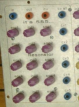
1 It s 555 resonator build info nonlinearcircuits BOM BC npn marked n on PCB see notes BC pnp- marked p on PCB see notes 555 IC 5 TL072 2 TL074 1 power connector Molex 3 pin 100k pots 15 see notes 10uF electro caps 7 value not marked on PCB, 2mm spacing decoupling caps 47nF- 100nF 15 value not marked on PCB 2.5mm spacing 1nF caps mm spacing 10nF caps 5 2.5mm spacing cp caps (10nF?) 5 see notes 4.5mm spacing 100nF cap 1 4.5mm spacing 10R 2 1k 2 1k8 5 2k k k k 5 330k 5 1M 1 1N4004 diodes 2 optional, for reverse voltage protection notes: matching trannies and cp caps. You do not have to match the transistors into pairs but do it if you can. You may still have to select different values for one or two of the cp capacitors. cp caps refers to the capacitors marked cp on the PCB.
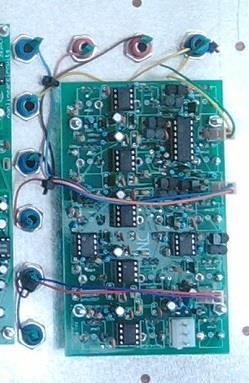
2 The cp capacitors and the transistors (which form a VC resistor) control the pulse width of the signal from each 555. You may have to experiment here. I find unmatched transistors and cp capacitors of 10nF give a good pulse width range, but on stage two I had to install a 1uF cap to get a decent pulse width. I have built three of these and usually have to change a few capacitors to get a good pulse width on each stage. The original design used 500pF caps but I find these to give a very narrow pulse and make the resonator sound weedy, maybe some people like this? I suggest install 10nF caps for the spaces marked cp on the PCB, but when testing the circuit be prepared to change out one or two of them to a larger value. So have a few different values on hand up to 1uF. pots These are a common footprint, if you have built any of my boards before you know what to get. I use 100k pots from Song Huei - R0903N-B100k, L-25KC (the 25 is the length L). It seems a pretty common footprint. Another pot that fits is this Alpha from Altronics - You should find similar types from Mouser, Rapid, etc. Some pots have metal tabs that may sit on top of a track, I usually bend these tabs inwards on the pots where this happens. Most of them are fine; probably no need to do this but an ounce of prevention etc. decoupling caps There is a 10uF and 100nF decoupling cap for each 555 IC, plus a load of others around the board. This is maybe overkill but 555s are famous for being gluttonous & noisy chips so best to try and keep the power rails clean and decouple away! BUILDING It is very important to install all of the IC sockets first, many of the resistors sit very close to the ICs and it will be very difficult to install the sockets after the resistors. The second job would be to fix the error, if you can be bothered; it still works if you don t see next section. Again the board is so packed it will be very hard to fix the error after installing everything else. After this, just go the usual route; resistors, trannies, caps. When installing the pots, I put them on the board but do not solder them. I then attach the board to the panel and make sure all of the pots are straight and level. Once this is done, I solder on the pots and their side tabs. ERROR! There is an error on the PCB, if you do not fix it, everything will still work except that the Initial and Env pots for stage three will control the pulse width of stage four and the pots for stage four will control the pulse width of stage three. If you want to fix this, you need to cut two tracks and install two jumper wires, do this early in the build. The board gets very full and it will be hard to cut tracks and add wires with lots of components on the board. See pics below for a guide:
3
4

5 Wiring There are 9 sockets to connect Env 1-5 are CV inputs for each stage. In is the audio input Env all is a CV input that will modulate all 5 stages Out is the main output Inv is the inverted positive components of the main output signal.

6 Sorry, not the greatest schematic, am using new software and yet to figure out how to export it nicely. Everything in the box appears 5 times, everything outside of the box appears once!
7
8
nonlinearcircuits QUO/LPF build notes version 2 11 April 2014
 nonlinearcircuits QUO/LPF build notes version 2 11 April 2014 This circuit is based on the 4 pole LPF in Electronotes 41, tho has been subject to a number of tweaks and prods to bring it to where it is
Double Penetration (DP) Filter nonlinearcircuits
 Filter nonlinearcircuits") Double Penetration (DP) Filter nonlinearcircuits Build guide & BOM Vers.1 18/1/2014 Large schematic is here - http://www.sdiy.org/pinky/data/bipolar%20vcfs.pdf Module description - http://www.sdiy.org/pinky/data/bp.html
Double Penetration (DP) Filter nonlinearcircuits Build guide & BOM Vers.1 18/1/2014 Large schematic is here - http://www.sdiy.org/pinky/data/bipolar%20vcfs.pdf Module description - http://www.sdiy.org/pinky/data/bp.html
nonlinearcircuits NULL-A 2 Build & BOM
 nonlinearcircuits NULL-A 2 Build & BOM Null-A 2 is an all-in-one analogue synth packed into 42HP. It features: 2 VCOs 1 state variable VCF 1 ladder VCF 1 VC Delay 3 VCAs 2 LFOs Mixer Headphone amp Sequencer
Discrete Op-Amp Kit MitchElectronics 2019
 Discrete Op-Amp Kit MitchElectronics 2019 www.mitchelectronics.co.uk CONTENTS Introduction 3 Schematic 4 How It Works 5 Materials 9 Construction 10 Important Information 11 Page 2 INTRODUCTION Even if
555 Astable Kit MitchElectronics 2018
 555 Astable Kit MitchElectronics 2018 www.mitchelectronics.co.uk CONTENTS Introduction 3 Schematic 3 How It Works 4 Materials 6 Construction 7 Important Information 8 Page 2 INTRODUCTION The 555 timer
BMC029. Single Multiplier/Divider Last updated
 BMC029. Single Multiplier/Divider Last updated 1-4-2015 I Features -What it does/controls -Demos II Schematics -Pinout -Controls -Inputs -Output III Construction -Parts List -PCB information -How to Install
AMSynths AM8044 VCF & VCA. Project Notes V2.0
 AMSynths AM8044 VCF & VCA Project Notes V2.0 AMSynths 2013 Rob Keeble Contact: sales@amsynths.co.uk Web Site: www.amsynths.co.uk 18 May 2013 1 Module Description This module is designed around the SSM2044
LITTLE NERD v1.1 Assembly Guide
 last update: 9. 3. 2016 LITTLE NERD v1.1 Assembly Guide bastl instruments.com INTRODUCTION This guide is for building Little Nerd module from Bastl Instruments. It is good to have basic soldering skills
ABC V1.0 ASSEMBLY IMPORTANT!
 ABC V1.0 ASSEMBLY Before starting this kit, prepare the following tools: Soldering iron (15-20W will do), flush cutters, no.2 hex screwdriver or allen key and phillips screwdriver. Also briefly go through
TS500 Assembly guide. Soldering. TS500 Assembly guide Main PCB 1. Diodes. Document revision 1.2 Last modification : 17/12/16
 TS500 Assembly guide Safety warning The kits are main powered and use potentially lethal voltages. Under no circumstance should someone undertake the realisation of a kit unless he has full knowledge about
THE GREEN CURRANT TREMOLO Build Document last updated june 2017 for PCB version 1.5
 THE GREEN CURRANT TREMOLO Build Document last updated june 2017 for PCB version 1.5 The Green Currant tremolo is a very percussive and vibey tremolo based around the TDA7052A amplifier chip. It splits
Multiwave. Guitar Synthesizer. Build Document last updated november 2018 Version
 Multiwave Guitar Synthesizer Build Document last updated november 2018 Version 1.0 2018 The Multiwave is a guitar controlled oscillator with 3 different waveshapes: saw, triangle and square. Combined,
Simple LFO Features. 2. Application. 3. Description. Simple and easy to build LFO module for Analog Synthesizers.
 Simple LFO. Simple and easy to build LFO module for Analog Synthesizers.. Features Square and Triangle waveforms (90 phase shifted) Dual range frequencies Frequency ranges from under Hz up to several khz
Multi-Window Comparator documentation. Written November 15, 2012 Last edited November 15, 2012
 Multi-Window Comparator documentation. Written November 15, 2012 Last edited November 15, 2012 I. What is a Multi-Window Comparator? A. A "regular" window comparator is this. B. A Multi-Window Comparator
Penrose Quantizer Assembly Guide
 Penrose Quantizer Assembly Guide Schematic and BOM The schematic can be found here: www.sonic-potions.com/public/penrosequantizerschematic.pdf The BOM is available at google docs: Link to BOM Prepare the
4ms SCM Breakout. Kit Builder's Guide for PCB v2.1 4mspedals.com
 4ms SCM Breakout Kit Builder's Guide for PCB v2.1 4mspedals.com Shuffling Clock Multiplier Breakout This guide is for building a Shuffling Clock Multiplier Breakout module (SCMBO) version 2.1 from the
PI3HDMI1210(-A) PI3HDMI1210-A Demo Board Rev.A User Manual
 PI3HDMI1210-A Demo Board Rev.A User Manual") PI3HDMI1210(-A) PI3HDMI1210-A Demo Board Rev.A User Manual Introduction This user manual describes the components and the usage of PI3HDMI1210(-A) demo Board Rev.A. Figure 1: Top View of PI3HDMI1210-A
PI3HDMI1210(-A) PI3HDMI1210-A Demo Board Rev.A User Manual Introduction This user manual describes the components and the usage of PI3HDMI1210(-A) demo Board Rev.A. Figure 1: Top View of PI3HDMI1210-A
BassAce - Midi Bass Synthesizer. BassAce Features
 Untitled Document BassAce - Midi Bass Synthesizer The BassAce is a small midi-synth based loosely on the TB303. It can be built many different ways. Depending on how it's configured it can be anything
J HAIBLE DUAL WASP VCF (Euro)
") J HAIBLE DUAL WASP VCF (Euro) Jürgen Haible s WASP Filter adaption of the famous CMOS VCF introduced some unique features, in particular a distortion stage. The R*S version takes this a step further by
J HAIBLE DUAL WASP VCF (Euro) Jürgen Haible s WASP Filter adaption of the famous CMOS VCF introduced some unique features, in particular a distortion stage. The R*S version takes this a step further by
5U Oakley Modular Series. Dual Comparator and Gate Delay CV and Audio Processor
 Oakley Sound Systems 5U Oakley Modular Series Dual Comparator and Gate Delay CV and Audio Processor PCB Issue 2 Builder s Guide V2.1 Tony Allgood Oakley Sound Systems CARLISLE United Kingdom The suggested
BMC017. 2LFOSH Last updated I Features II Schematics III Construction
 BMC017. 2LFOSH Last updated 12-3-2013 I Features II Schematics III Construction I. Features The 2LFOSH module is a combination of three different modules on one board, designed to be easy to be easy to
N3ZI Kits General Coverage Receiver, Assembly & Operations Manual (For Jun 2011 PCB ) Version 3.33, Jan 2012
 Version 3.33, Jan 2012") N3ZI Kits General Coverage Receiver, Assembly & Operations Manual (For Jun 2011 PCB ) Version 3.33, Jan 2012 Thank you for purchasing my general coverage receiver kit. You can use the photo above as a
N3ZI Kits General Coverage Receiver, Assembly & Operations Manual (For Jun 2011 PCB ) Version 3.33, Jan 2012 Thank you for purchasing my general coverage receiver kit. You can use the photo above as a
BMC052. Chordizer Last updated
 BMC052. Chordizer Last updated 8-27-2017 If you have any questions, or need help trouble shooting, please e-mail Michael@Bartonmusicalcircuits.com I Overview/Controls/Inputs/Outputs II Schematic III Construction
WHISTLE ROCK AUDIO ML12 PSU KIT/PCB
 WHISTLE ROCK AUDIO ML12 PSU KIT/PCB TABLE OF CONTENTS 1. INTRODUCTION Page 3 2. BILL OF MATERIAL Page 4 3. ALTERNATE RESISTOR VALUES Page 5 4. ASSEMBLY GUIDE Page 6 to 11 5. CONNECTIONS Page 12 6. SETUP
Thomas Henry s VCO MAXIMUS (Eurorack DIY)
") Thomas Henry s VCO MAXIMUS (Eurorack DIY) Introduction Back in 1987 Thomas Henry published the CEM3340 based Deluxe VCO in his book Build A Better Music Synthesizer. Alas, in the following years everything
Thomas Henry s VCO MAXIMUS (Eurorack DIY) Introduction Back in 1987 Thomas Henry published the CEM3340 based Deluxe VCO in his book Build A Better Music Synthesizer. Alas, in the following years everything
Electric Druid Flangelicious Flanger Project
 Electric Druid Flangelicious Flanger Project (Using either 4KNOBFLANGE or MULTIFLANGE chips) Overview! 2 Build Instructions! 2 Populate the PCB! 2 1N4148 Diodes! 2 Resistors! 2 Cup of tea and soldering
Pingable Envelope Generator
 Pingable Envelope Generator Kit Builder's Guide for PCB v1.0.3 4mspedals.com PEG This guide is for building a Pingable Envelope Generator (PEG), which is an intermediate-level kit. You should be confident
INTO THE UNKNOWN Build Document last updated may 2016 Version
 INTO THE UNKNOWN Build Document last updated may 2016 Version 1.0 2015 'Into the Unknown Guitar Synthesizer Deluxe' is a CMOS based fuzz centered around the CD4046 PLL (phase locked loop) chip and a CD4015
AMSynths. AM8040 Voltage Controlled Low Pass Filter. Project Notes V2.2
 AMSynths AM8040 Voltage Controlled Low Pass Filter Project Notes V2.2 AMSynths 2013 Rob Keeble Contact: sales@amsynths.co.uk Web Site: www.amsynths.co.uk 29 June 2013 1 Module Description This module is
A3930 and A3931. Demo Board Schematic/Layout SCHEMATIC A DB
 SCHEMATIC A3930-31-DB LAYOUT 2 3 4 BILL OF MATERIALS A3930/ Demo Board Rev 3 Component List Last Updated: 15/07/2014 Part Value Package Description RS Part Part Value Package Description RS Part C1 1000uF
Guitarpedalkits.com Overdrive Pedal Build Instructions
 Page 1 Guitarpedalkits.com Overdrive Pedal Build Instructions Follow the instructions in this guide to build your very own DIY overdrive pedal from GuitarPedalKits.com. If you re a first time builder,
R*S Stereo Mixer V1.2
 R*S Stereo Mixer V1.2 The Random*Source Equal Power Stereo-Mixer is a voltage controlled stereo mixer / panner / VCA based on 4 high-end THAT2180 blackmer VCAs, designed to emulate the behavior of Serge
CV Arpeggiator Rev 1. Last updated
 CV Arpeggiator Rev Last updated 6--20 The CV Arpeggiator is a modular synth project used for creating arpeggios of control voltage. It utilizes a custom programmed PIC 6F685 micro controller. It includes
Ocean Controls KT-5198 Dual Bidirectional DC Motor Speed Controller
 Ocean Controls KT-5198 Dual Bidirectional DC Motor Speed Controller Microcontroller Based Controls 2 DC Motors 0-5V Analog, 1-2mS pulse or Serial Inputs for Motor Speed 10KHz, 1.25KHz or 156Hz selectable
Stage Fright 2015 edition FX TYPE: Phaser Based on the Maestro Phaser 2015 madbeanpedals
 Stage Fright 2015 edition FX TYPE: Phaser Based on the Maestro Phaser 2015 madbeanpedals 2.3" W x 3.45" H Previous Version: http://www.madbeanpedals.com/stagefright/stagefright.zip Terms of Use: You are
Ultimatum Fuzz. The Ultimate experience in vintage-style octave-up fuzz
 Ultimatum Fuzz The Ultimate experience in vintage-style octave-up fuzz Contents of this document are 2015 Pedal Parts Ltd. No reproduction permitted without the express written permission of Pedal Parts
R*S Stereo Mixer V1.3
 R*S Stereo Mixer V1.3 The Random*Source Equal Power Stereo-Mixer is a voltage controlled stereo mixer / panner / VCA based on 4 high-end THAT2180 blackmer VCAs, designed to emulate the behavior of Serge
Axis Fuzz Kit Building Manual
 Axis Fuzz Kit Building Manual Effect Pedal Kits: Axis Fuzz The Axis Fuzz Kit is based in the Roger Mayer Axis Fuzz, the effect pedal responsible for Jimi Hendrix sound in Axis Bold As Love. What else is
LED Field Strength Indicator Kit
 LED Field Strength Indicator Kit Description The Field Strength Indicator kit from Qrpkits.com provides a visual way to monitor RF fields through the brightness of an LED. It will respond to RF fields
Dig Dug madbeanpedals FX Type: Sequencer W x 3.25 H
 Dig Dug2 2015 madbeanpedals FX Type: Sequencer 4.15 W x 3.25 H B.O.M. Resistors Caps Diodes R1 1M C1 100n D1 1N5817 R2 1M C2 220n D2 - D4 1n914 R3 10k C3 15n LED1-8 3mm Red R4 330k C4 2n2 PATT 3mm Red
LunarBlast v1.0. Optical Tremolo. Description:
 LunarBlast v1.0 Optical Tremolo Description: Based on the venerable DIY Tremulus Lune classic circuit, www.madbean.com forum member CultureJam created this awesome sounding tremolo dubbed the Shoot the
BMC018. Analog Drum. Last updated
 BMC018. Analog Drum. Last updated 11-26-2013 I Features II Schematics A.Master Schematic. B.Input/Decay C.VCO D.VCA E.Power Connections. III Construction A.Parts List B.The Board I. Features This module
LAYOUTS. Thomas Henry SSM2164 VCF/VCA v1. Adapter PCB top view (Panel side) Main PCB. Adapter PCB bottom view. 9/13/2016
 Main PCB. Adapter PCB bottom view. 9/13/2016") Thomas Henry SSM VCF/VCA v LAYOUTS The PCB/Panel combo is comprised of one main PCB, an adapter PCB, and an Eurorack format panel. Nevertheless, one can always use just the main PCB to build a module in
Thomas Henry SSM VCF/VCA v LAYOUTS The PCB/Panel combo is comprised of one main PCB, an adapter PCB, and an Eurorack format panel. Nevertheless, one can always use just the main PCB to build a module in
BMC040. Dual Logic. Last updated
 BMC040. Dual Logic. Last updated 2-1-2016 If you have any questions, or need help trouble shooting, please e-mail Michael@Bartonmusicalcircuits.com I Overview/Features II Schematic III Construction A.Parts
The Sudden Storm & Rexwood 1000W Kits. from QRPme. Builder s Guide. Version 6.2. for. Sudden Storm ][ ver.6 Rexwood 1000W ver.6. Updated 12/18/2017
![The Sudden Storm & Rexwood 1000W Kits. from QRPme. Builder s Guide. Version 6.2. for. Sudden Storm ][ ver.6 Rexwood 1000W ver.6. Updated 12/18/2017](/thumbs/89/98806822.jpg "The Sudden Storm & Rexwood 1000W Kits. from QRPme. Builder s Guide. Version 6.2. for. Sudden Storm ][ ver.6 Rexwood 1000W ver.6. Updated 12/18/2017") The Sudden Storm & Rexwood 1000W Kits from QRPme Builder s Guide Version 6.2 for Sudden Storm ][ ver.6 Rexwood 1000W ver.6 Updated 12/18/2017 Open the can and the adventure begins 1 Organize the parts
The Sudden Storm & Rexwood 1000W Kits from QRPme Builder s Guide Version 6.2 for Sudden Storm ][ ver.6 Rexwood 1000W ver.6 Updated 12/18/2017 Open the can and the adventure begins 1 Organize the parts
Rotary Relay Replacement. for the ICOM 720A KA6BFB
 Rotary Relay Replacement for the ICOM 720A by KA6BFB BACKGROUND There are several modifications available for converting the Icom IC-720A rotary relay in the filter module to fixed relays. The most popular
SERGE Ring Modulator 2017 (RING) for Eurorack
 for Eurorack") SERGE Ring Modulator 2017 (RING) for Eurorack The 2017 RING is an improved version of the late Serge Ring Modulator (R9), designed by Serge himself for Random*Source in 2017, more than 40 years after the
SERGE Ring Modulator 2017 (RING) for Eurorack The 2017 RING is an improved version of the late Serge Ring Modulator (R9), designed by Serge himself for Random*Source in 2017, more than 40 years after the
Build Your Own Clone The Swede Kit Instructions
 Build Your Own Clone The Swede Kit Instructions Warranty: BYOC, Inc. guarantees that your kit will be complete and that all parts and components will arrive as described, functioning and free of defect.
BYOC Vibrato Kit Instructions BA6110 version
 BYOC Vibrato Kit Instructions BA6110 version Please read these instructions very thoroughly before building even if you are an experience builder. Because of the
Cave Dweller 2015 edition FX Type: Delay 2015 madbeanpedals
 Cave Dweller 2015 edition FX Type: Delay 2015 madbeanpedals 1.3" W x 1.975" H (main board) Previous Version: http://www.madbeanpedals.com/projects/cavedweller/cavedweller_drill.zip Terms of Use: You are
FREEKOUT FX TYPE: Ring Modulator Based on the EHX Frequency Analyzer 2015 madbeanpedals
 FREEKOUT FX TYPE: Ring Modulator Based on the EHX Frequency Analyzer 2015 madbeanpedals 2.3 W x 3.025 H This project requires an 18v 100mA (or more) center tip negative power supply. I recommend the Dunlop
LA502 Assembly guide Main PCB Resistors - (2)
") LA502 Assembly guide Safety warning The kits are main powered and use potentially lethal voltages. Under no circumstance should someone undertake the realisation of a kit unless he has full knowledge about
LA502 Assembly guide Safety warning The kits are main powered and use potentially lethal voltages. Under no circumstance should someone undertake the realisation of a kit unless he has full knowledge about
Build Guide CascadiA. GeFet Preamp
 Build Guide CascadiA GeFet Preamp Disclaimery stuff: This project is meant to be assembled by fellow DIYers from the Madbean forum and should only be used for the forces of good. Any other uses prohibited
Workshop Part Identification Lecture N I A G A R A C O L L E G E T E C H N O L O G Y D E P T.
 Workshop Part Identification Lecture N I A G A R A C O L L E G E T E C H N O L O G Y D E P T. Identifying Resistors Resistors can be either fixed or variable. The variable kind are called potentiometers
LBI-38392C IC DATA MAINTENANCE MANUAL LOGIC BOARD U707 OCTAL DATA LATCH 19D902172G1 & G2 TABLE OF CONTENTS
 LBI-38392C MAINTENANCE MANUAL LOGIC BOARD 19D902172G1 & G2 U707 OCTAL DATA LATCH IC DATA TABLE OF CONTENTS Page DESCRIPTION........................................... Front.. Cover CIRCUIT ANALYSIS........................................
Build Your Own Clone Li l Echo Kit Instructions
 Build Your Own Clone Li l Echo Kit Instructions Warranty: BYOC, Inc. guarantees that your kit will be complete and that all parts and components will arrive as described, functioning and free of defect.
RM4014 Ring Modulator
 Oakley Sound Systems Oakley Modular Eurorack Series RM4014 Ring Modulator PCB Issue 3E Builder's Guide V3.2 Tony Allgood Oakley Sound Systems CARLISLE United Kingdom Introduction The issue 3E PCB fitted
Conversion of a DC-AC inverter to 400 Hz
 Conversion of a DC-AC inverter to 400 Hz By F6FER Roger CCAE#016 Conversion of a DC-AC inverter to 400 Hz As a user of a 618T-3, I was needing a power supply putting out around 150 VA under 115V at 400
TLN-428 Voltage Controlled State Variable Filter
 The Tellun Corporation TLN-428 Voltage Controlled State Variable Filter User Guide, Rev. 1.1 Scott Juskiw The Tellun Corporation scott@tellun.com TLN-428 User Guide Revision 1.1 March 16, 2003 Introduction
NEW WAVE CV GENERATOR Build Document last updated september 2017 for PCB version 1.0
 NEW WAVE CV GENERATOR Build Document last updated september 2017 for PCB version 1.0 The New Wave is a Control Voltage Generator. It has two LFO's (low frequency oscillators) and four different output
The Tellun Corporation. TLN-442 Voltage Controlled Lowpass Filter. User Guide, Rev Scott Juskiw The Tellun Corporation
 The Tellun Corporation TLN-442 Voltage Controlled Lowpass Filter User Guide, Rev. 1.1 Scott Juskiw The Tellun Corporation scott@tellun.com TLN-442 User Guide Revision 1.1 March 15, 2003 Introduction The
2.15 W x 1.95 H. Changes to the 2015 edition
 NOM NOM FX Type: Filter 2015 edition Based on the MXR Phase 90 2015 madbeanpedals Download the previous version documentation here: http://www.madbeanpedals.com/projects/nomnom/nomnom.zip 2.15 W x 1.95
Classic VCA. Builder's Guide. Oakley Sound Systems. 5U Oakley Modular Series. Discrete VCA PCB Issue 1 V1.0.1
 Oakley Sound Systems 5U Oakley Modular Series Classic VCA Discrete VCA PCB Issue 1 Builder's Guide V1.0.1 Tony Allgood Oakley Sound Systems CARLISLE United Kingdom Introduction This is the Project Builder's
Value Location Qty Potentiometers C1M Distortion 1 A10k Volume 1. Footswitch 3PDT SW1 1. Jacks 1/4 Mono 2 DC Power 1
 Distortion BUILD INSTRUCTIONS Thank you for your purchase of our Distortion+ kit! We have completely redesigned our entire line of kits to be the most user friendly, while still maintaining their same
MICROGRANNY v2.1 - Assembly Guide
 last update: 9. 5. 2017 MICROGRANNY v2.1 - Assembly Guide bastl-instruments.com INTRODUCTION Welcome to the assembly guide for the MicroGranny kit. MicroGranny is a monophonic granular sampler by Bastl
BYOC Vibrato Kit Instructions BA662A version
 BYOC Vibrato Kit Instructions BA662A version Please read these instructions very thoroughly before building even if you are an experience builder. Because of the layout, there is a certain order which
V-TUNE. Variable capacitance mini-circuit with Varactor diode and potentiometer control. Assembly manual. Last updated: July 15, 2017
 V-TUNE Variable capacitance mini-circuit with Varactor diode and potentiometer control Assembly manual Last updated: July 15, 2017 ea3gcy@gmail.com Updates and news at: www.ea3gcy.com Thanks for building
Equinoxe Voltage Controlled Phaser
 Oakley Sound Systems 5U Oakley Modular Series Equinoxe Voltage Controlled Phaser PCB Issue 5 Builder's Guide V5.4 Tony Allgood Oakley Sound Systems CARLISLE United Kingdom The 1U wide panel design for
Build Your Own Clone Crown Jewel Kit Instructions
 Build Your Own Clone Crown Jewel Kit Instructions Warranty: BYOC, Inc. guarantees that your kit will be complete and that all parts and components will arrive as described, functioning and free of defect.
How to build a Cracklebox. Red Wierenga Brooklyn College Center for Computer Music October 13, 2015
 How to build a Cracklebox Red Wierenga Brooklyn College Center for Computer Music October 13, 2015 What s a Cracklebox? What s a Cracklebox? The Cracklebox was developed by Michel Waisvisz and others at
BMC016. Dual Nice Quantizer. Last updated new calibration instructions
 BMC016. Dual Nice Quantizer. Last updated 8-19-2018 new calibration instructions There are two versions of this PCB, if you have a PCB with six trimpots, read THIS DOCUMENTATION instead. I Using The Dual
Pacific Antenna Field Strength Indicator Kit
 Pacific Antenna Field Strength Indicator Kit Description The Field Strength Indicator kit from Pacific Antenna provides a visual way to monitor the presence and relative strength RF fields through the
LBI-39061A. Installation Manual. DTMF Encoder 344A4209P23 (MHDE5U) ericssonz
 ericssonz") LBI-39061A Installation Manual DTMF Encoder 344A4209P23 (MHDE5U) ericssonz TABLE OF CONTENTS Page INTRODUCTION...3 GENERAL DESCRIPTION...3 PROGRAMMING...3 THEORY OF OPERATION...3 INSTALLATION AND ALIGNMENT...4
LBI-39061A Installation Manual DTMF Encoder 344A4209P23 (MHDE5U) ericssonz TABLE OF CONTENTS Page INTRODUCTION...3 GENERAL DESCRIPTION...3 PROGRAMMING...3 THEORY OF OPERATION...3 INSTALLATION AND ALIGNMENT...4
Electric Druid 4 second Digital Delay Project
 Electric Druid 4 second Digital Delay Project Overview! 2 Build Instructions! 2 Populate the PCB! 2 Resistors! 2 Cup of tea and soldering check! 3 Power protection diode! 4 Ground link wire! 4 IC sockets!
Instructions for Building the Pulsed Width Modulation Circuit. MC-12 (DC Motor Controller or PWM) From Electronic Light Inc.
 From Electronic Light Inc.") Instructions for Building the Pulsed Width Modulation Circuit MC-2 (DC Motor Controller or PWM) From Electronic Light Inc. (revised 3/08) Using this circuit for a pulsed DC current to your cell, Do NOT
Instructions for Building the Pulsed Width Modulation Circuit MC-2 (DC Motor Controller or PWM) From Electronic Light Inc. (revised 3/08) Using this circuit for a pulsed DC current to your cell, Do NOT
Build Your Own Clone Li l Reverb Kit Instructions
 Build Your Own Clone Li l Reverb Kit Instructions Warranty: BYOC, Inc. guarantees that your kit will be complete and that all parts and components will arrive as described, functioning and free of defect.
PAM8406 EVB User Guide
 EV Board User Guide AE Department. Revision Information PAM8406 Date Revision Description Comment 0//5 V.0 Initial Release. EV Board Schematic J5 + C C R C6 R C7 C FB FB C0 SP J4 C5 VREF 8 INL 7 6 MUTE
FM Audio/Squelch Board by Steve Dold, W6KCS w6kcs (at) stevedold (dot) com
 stevedold (dot) com") FM Audio/Squelch Board by Steve Dold, W6KCS w6kcs at stevedold dot com Board hardware version 7-8 Firmware version 7.x This board connects to an FM receiver's discriminator/detector and provides squelched,
FM Audio/Squelch Board by Steve Dold, W6KCS w6kcs at stevedold dot com Board hardware version 7-8 Firmware version 7.x This board connects to an FM receiver's discriminator/detector and provides squelched,
Starving Student II. Starving Student II. SS2 guide. Written By: 6L guides.diyaudio.com/ Page 1 of 24
 SS2 guide Written By: 6L6 2019 guides.diyaudio.com/ Page 1 of 24 INTRODUCTION This is a build guide for the hybrid headphone/pre-amplifier. You can buy a kit at the SSII product listing on the diyaudio
Instructions for Building the Pulsed Width Modulation Circuit. MC-12 (DC Motor Controller or PWM) From Electronic Light Inc. (revised kit 5/08)
 From Electronic Light Inc. (revised kit 5/08)") Instructions for Building the Pulsed Width Modulation Circuit MC-12 (DC Motor Controller or PWM) From Electronic Light Inc. (revised kit 5/08) Using this circuit for a pulsed DC current to your cell. Do
Instructions for Building the Pulsed Width Modulation Circuit MC-12 (DC Motor Controller or PWM) From Electronic Light Inc. (revised kit 5/08) Using this circuit for a pulsed DC current to your cell. Do
UM1360 Evaluation Board User s Guide
 UM1360 Evaluation Board User s Guide Version Date Provider Approve Note 1.0 2012-11-02 LB Initial version. Table of Contents 1. Board Information 1.1 Schematic 1.2 PCB Layout 1.3 Jumper and Test Point
MP573 Assembly guide. Soldering. MP573 Assembly guide PCB split PCB split. Document revision 2.2 Last modification : 22/08/17
 MP573 Assembly guide Safety warning The kits are main powered and use potentially lethal voltages. Under no circumstance should someone undertake the realisation of a kit unless he has full knowledge about
Total Recall FX Type: Delay Based on the EHX Deluxe Memory Man 2015 madbeanpedals
 Total Recall FX Type: Delay Based on the EHX Deluxe Memory Man 2015 madbeanpedals 3.34" W x 3.875" H Terms of Use: You are free to use purchased Total Recall circuit boards for both DIY and small commercial
FM RADIO KIT ESSENTIAL INFORMATION. Version 2.0 GET IN TUNE WITH THIS
 ESSENTIAL INFORMATION BUILD INSTRUCTIONS CHECKING YOUR PCB & FAULT-FINDING MECHANICAL DETAILS HOW THE KIT WORKS GET IN TUNE WITH THIS FM RADIO KIT Version 2.0 Build Instructions Before you start, take
DIY Function Generator XR2206
 DIY Function Generator XR2206 20Hz 100KHz http://radiohobbystore.com Components List: Resistors: R1, R2 1% Metal Film 5K1 R4 1% Metal Film 10K R5 1% Metal Film 3K R10 5% Carbon Film 10R R3, R9 Potentiometer
KK1L Icom Band Decoder Basic Assembly
 KK1L Icom Band Decoder Basic Assembly Ronald Rossi, KK1L http://home.comcast.net/~kk1l Features: RFI isolated inputs Fully opto-isolated Replaces one BCD band decode port on KK1L dual decoder Description:
Geiger Counter Kit Assembly Instructions ( )
") Geiger Counter Kit Assembly Instructions (2012-05-11) To build this kit, you should know how to solder. And it will be much easier if you have made other kits before. But even if this is your first kit,
Geiger Counter Kit Assembly Instructions (2012-05-11) To build this kit, you should know how to solder. And it will be much easier if you have made other kits before. But even if this is your first kit,
SERGE Wave Multipliers (VCM)
") SERGE Wave Multipliers (VCM) The legendary Serge Wave Multipliers (VCM) are a module - or rather 3 modules - designed to dynamically add new harmonically-related overtones to an input waveform. Accroding
SERGE Wave Multipliers (VCM) The legendary Serge Wave Multipliers (VCM) are a module - or rather 3 modules - designed to dynamically add new harmonically-related overtones to an input waveform. Accroding
Auto-Seq Documentation Written April 6th, 2014
 Auto-Seq Documentation Written April 6th, 2014 I. Using The Module A. What is Auto-Seq? B. Controls/Inputs/Outputs C. Sample Patches II. Schematics A.Chip Pinout B.Inputs 1.Analog Inputs 2.Digital Inputs
Standard JFET input buffer and Standard NPN Output buffer
 Board Standard JFET input buffer and Standard NPN Output buffer By PCB Guitar mania Mania Project link The buffers are normally added into a circuit to prevent loading and loss of definition of the guitar
Application Note. I C s f o r M o t o r C o n t r o l. Evaluation board for the TDA5143/TDA5144. Report No: EIE/AN R. Galema
 Application Note I C s f o r M o t o r C o n t r o l Evaluation board for the TDA5143/TDA5144 Report No: R. Galema Product Concept & Application Laboratory Eindhoven, the Netherlands. Keywords Motor Control
DeluxeArcade. JAMMA Fingerboard. Introduction. Features. Version 1.1, November 2014 Martin-Jones Technology Ltd
 DeluxeArcade JAMMA Fingerboard Version., November 204 Martin-Jones Technology Ltd http://www.martin-jones.com/ Introduction The Deluxe Arcade JAMMA Fingerboard is designed to make adapting non-jamma arcade
PulsePuppy Installation and Operation Manual Oscillator Carrier Revised: 30 January TAPR
 PulsePuppy Installation and Operation Manual Oscillator Carrier Revised: 30 January 2018 2018 TAPR Introduction The PulsePuppy is a carrier board for small user-provided oven controlled ( OCXO ) and temperature
LP2+delay board Yellow Magic
 LP+delay board Yellow Magic This filter boards combines a raw OTA-C -pole filter, combined with a classic lo-fi delay. Using this filter board Important! The Phoenix/Shruthi- control board needs to send
Materials. Eight pin DIP socket 0.1 µf capacitor
 JOE GROELE Project Outline The goal of this project was to build a plasma speaker that will amplify an electric guitar sound. Build an audio oscillator circuit using an ordinary speaker Test speaker performance
Build Your Own Clone Classic Phaser Kit Instructions
 Build Your Own Clone Classic Phaser Kit Instructions Warranty: BYOC, Inc. guarantees that your kit will be complete and that all parts and components will arrive as described, functioning and free of defect.
Dirtbaby FX TYPE: Delay Based on the EHX DMM 2016 madbeanpedals
 Dirtbaby FX TYPE: Delay Based on the EHX DMM 2016 madbeanpedals 3.325 W x 2.325 H Terms of Use: You are free to use purchased circuit boards for both DIY and small commercial operations. You may not offer
5U Oakley Modular Series
 Oakley Sound Systems 5U Oakley Modular Series VC-LFO Low Frequency Oscillator PCB Issue 2 Builder s Guide V2.0.05 Tony Allgood B.Eng PGCE Oakley Sound Systems CARLISLE United Kingdom The suggested panel
The B7 Discrete Operational Amplifier Author: Tamas G. Kohalmi 7/5/2004
 The B7 Discrete Operational Amplifier Author: Tamas G. Kohalmi 7/5/2004 Table of Contents Part 1... pages 2-4 Part 2 pages 5-7 Part 1. This document describes a simple discrete operational amplifier that
TKEY-1. CW touch key. (no electromechanical contacts) Assembly manual. Last update: May 1,
 Assembly manual. Last update: May 1,") TKEY-1 CW touch key (no electromechanical contacts) Assembly manual Last update: May 1, 2016 ea3gcy@gmail.com Updates and news at: www.qsl.net/ea3gcy Thanks for constructing the TKEY-1A CW touch key Have
TKEY-1 CW touch key (no electromechanical contacts) Assembly manual Last update: May 1, 2016 ea3gcy@gmail.com Updates and news at: www.qsl.net/ea3gcy Thanks for constructing the TKEY-1A CW touch key Have