WHISTLE ROCK AUDIO ML12 PSU KIT/PCB
|
|
|
- Aileen Jodie Neal
- 5 years ago
- Views:
Transcription

1 WHISTLE ROCK AUDIO ML12 PSU KIT/PCB
2 TABLE OF CONTENTS 1. INTRODUCTION Page 3 2. BILL OF MATERIAL Page 4 3. ALTERNATE RESISTOR VALUES Page 5 4. ASSEMBLY GUIDE Page 6 to CONNECTIONS Page SETUP GUIDE Page 13 and REFERENCE PICTURES Page SCHEMATIC Page PCB TOP SILK Page 17 (last page) DISCLAIMER I am not liable for any damage, harm or loss of any kind resulting from the assembly and/or use of this kit. This kit contains small parts that may be easily swallowed by a child. Keep all components of the kit AWAY from children and animals. Finally, always take necessary precautions when handling potentially dangerous tools such as cutters, scissors, soldering iron, etc. 2

3 INTRODUCTION Thank you for purchasing the ML12 PSU Kit/PCB. This power supply is designed for the Whistle Rock Audio ML12 microphone preamplifier, however, it is very well suited for many other kind of projects. Whether your project requires a single positive rail or bipolar rails, this flexible PSU design will allow you to choose the configuration that fits best. It provides four separate regulated voltage rails: A single negative rail, two positive rails and a +48V phantom power voltage rail. The third voltage rail can be used to activate relays or power up LEDs. It can also be used to power up the CMOS/TTL logic circuits in your project. The last two pages of this document contain the schematic and silkscreen layout that can be printed out as a reference when assembling the PSU. Have fun! Sincerely, Michael Lebon Contact: mike@whistlerockaudio.com ML12 PSU features: Linear power supply, 317/337 based. Four regulated output voltages. Star grounding point available. Third rail regulator can be fed from the second rail output or from bridge rectifier. All voltages are fine trimmed via multi-turn Bourns potentiometers. Ample decoupling capacitors per rail. Wide range of compatible power transformers. All connections are done via screw terminal block. Optional Molex 0.1 header power output port. Indicator LEDs connect directly to the PSU board. High quality parts throughout. PCB is professionally manufactured with UL and RoHS certified process. All components are Lead Free/RoHS compliant. 3

4 BILL OF MATERIAL Reference Description Retailer Retailer. Part # Qty. C1 to C4, C11 to C13, C17, C24, C uF, 50V Alum Electrolytic Cap Digikey P10333-ND 10 C5, C6, C9, C10, C14, C16, C20, C22 100nF, 100V Ceramic Cap Digikey ND 8 C7, C8, C15, C21 10uF, 100V Alum Electrolytic Cap Digikey P10769-ND 4 C18, C19, C23 150uF, 100V Alum Electrolytic Cap Digikey P10777-ND 3 D1 to D8 1A 1000V General Purpose Diode Digikey 1N4007FSCT-ND 8 BR1, BR2 2A 200V Bridge Rectifier Digikey 2KBP02M-E4/51GI-ND 2 AC_IN CONN 4 Position Terminal Block Digikey ND 1 POWER_OUT CONN 5 Position Terminal Block Digikey WM7856-ND 1 LED1, LED2 Green LED 2mm 2.2V Flat Top Digikey P613-ND 2 LED3 Amber LED 2mm 2.2V Flat Top Digikey P614-ND 1 LED4 Red LED 2mm 2.2V Flat Top Digikey P612-ND 1 RV1 to RV4 1K Trim Pot Digikey 3296W-102LF-ND 4 U1, U3, U4 LM317 Adjustable Positive Regulator Digikey ND 3 U2 LM337 Adjustable Negative Regulator Mouser 595-LM337KCSE3 1 R1, R3, R7, R Ohms - 1% Metal Film Resistors Mouser RC 4 R2, R4, R12 2.4K - 1% Metal Film Resistors Mouser K-RC 3 R5, R6 680 Ohms - 1% Metal Film Resistors Mouser RC 2 R8 1.5K - 1% Metal Film Resistor Mouser K-RC 1 R9 487 Ohms - 1% Metal Film Resistor Mouser RC 1 R11 8.6K - 1% Metal Film Resistor Mouser K-RC 1 The above values for R2, R4, R5, R6, R8 and R9 are assuming the following output voltages: -16V, +16V, +12V and +48V. 4
5 ALTERNATE RESISTOR VALUES First Rail Output Voltage -5V -12V -15V -16V -18V -20V -22V -24V -28V -30V R K 2K 2.4K 2.7K 3.3K 3.3K 3.9K 4.7K 4.99K R K 1.1K 1.3K 1.4K Second Rail Output Voltage 5V 12V 15V 16V 18V 20V 22V 24V 28V 30V R K 2K 2.4K 2.7K 3.3K 3.3K 3.9K 4.7K 4.99K R K 1.1K 1.3K 1.4K Third Rail Output Voltage 5V 12V 15V 16V 18V 20V 22V 24V 28V 30V R K 2K 2.4K 2.7K 3.3K 3.3K 3.9K 4.7K 4.99K R K 1.1K 1.3K 1.4K Fourth Rail Output Voltage The fourth rail is designed to provide a +48V phantom power voltage. There are no alternate resistor values available for that rail. 5


6 ASSEMBLY GUIDE The following information applies to the kit but may also help those with bare PCBs. Before starting assembly, identify every component in the kit. Compare the content of the kit with the BOM provided previously. If you can t make out the resistor values from the colour rings, use a multimeter to confirm their values. N.B.: If you have ordered a custom kit, make sure that you can clearly identify R2, R4, R5, R6, R8 and R9. The Alternate Resistor Values table (on page 5) lists all possible combinations of resistors that you may have received. Each rail will have certain components associated with it. The following is a list of the components needed to run each rail*. The pictures below are for visual reference only. FIRST RAIL: C2, C4, C12, C8, C6, C10, R3, R4, RV2, D3, D4 and U2. OPTIONAL LED: R6, LED2. SECOND RAIL: C1, C3, C5, C7, C9, C11, R1, R2, RV1, D1, D2 and U1. OPTIONAL LED: R5, LED1. *Thanks to Mark Plancke (Biasrocks) for the suggestion. 6


7 THIRD RAIL: JP2, C13, C14, C15, C16, C17, R7, R8, RV3, D5, D6 and U3. OPTIONAL LED: R9, LED3. FOURTH RAIL: C24, C25, C18, C19, C20, C21, C22, C23, R10, R11, RV4, D7, D8 and U4. OPTIONAL LED: R12, LED4. 7


8 STUFFING ORDER: a) - Resistors: Remember to check your resistor values before soldering them to the board. Use a multimeter if needed. b) - Diodes: Diodes are polarized components, which require a bit more attention when inserting them on the PCB. The cathode is clearly marked on the diode s body with a grey ring. It MUST match the marking on the PCB silkscreen. c) - Ceramic Capacitors (100nF): These ceramic capacitors are part of the decoupling circuits and eight are required if building a full kit. 8

 - Trim resistors: The trim resistors allow you to fine adjust the voltage outputs.")
 - Small Electrolytic Capacitors (10uF): These reside right beside the trim resistors. Notice that they are polarized components.")
9 d) - Jumpers: Two 3-pin headers and jumpers are included with a full 4-rail kit. They are to be used for JP1 and JP2. Custom kits may only have one or none depending on your rail requirements. Refer to the setup section on page 13 to understand what those jumpers do and how to configure them. e) - Trim resistors: The trim resistors allow you to fine adjust the voltage outputs. There are four of them in a full 4-rail kit: RV1, RV2, RV3 and RV4. Place them as indicated by the PCB silkscreen. f) - Small Electrolytic Capacitors (10uF): These reside right beside the trim resistors. Notice that they are polarized components. The band along the capacitor s body indicates the negative side. The positive side is marked on the PCB silkscreen. You MUST place these in the right direction. There are four of them in a full 4-rail kit: C7, C8, C15 and C21. 9


10 g) - Bridge Rectifiers: These are polarized and must be placed correctly on the PCB according to the silkscreen marking. The positive side is marked on the component and must match the rectangular marking on the PCB. If you have a custom kit that does not include the +48V rail, you will only find a single bridge rectifier to be used for BR1. h) - Screw Terminals: There are two screw-terminals to be placed. One has four positions for the power transformer connections and the other has five positions for the voltage outputs. e) - Voltage Regulators: The voltage regulators are placed along the edge of the PCB for easy heat sink mounting. 10

 Large Electrolytic Capacitors (150uF): Watch the polarity of these as")
11 f) - Large Electrolytic Capacitors (1000uF): Watch the polarity! The negative side is marked with a gold stripe along the component s body. There are ten of them in a full 4-rail PSU. g) Large Electrolytic Capacitors (150uF): Watch the polarity of these as well. The stripe indicates the negative side. 11
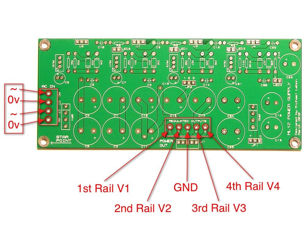
12 CONNECTIONS 12


13 This section will go over the proper setup of the PSU. STEP 1: Jumper settings. SETUP GUIDE JP1 is used only if a +48V rail is needed. It has two possible positions: D (doubler) or T (tripler). - JP1 must be set to the D position when the power transformer used is rated for 2x20 VAC or more. - JP1 must be set to the T position when the power transformer used is rated for 2x18 VAC or less. JP2 is used to set the unregulated voltage source of the third rail. - JP2 should be set to 2-3 if the third rail is set to provide a voltage equal to or greater than the second rail. - JP2 should be set to 1-2 if the third rail is set to provide a voltage lower than the second rail by more than 2V. STEP 2: Double-checking. This is VERY important! Make sure that every solder joint is properly done and double (and triple) check the polarity of the diodes and electrolytic capacitors. The silkscreen layout on page 15 is provided in this document as a reference. STEP 3: Smoke test! Once you are sure that all the components are properly placed, hook up the power transformer to the AC IN screw terminal block as described in the previous page. Now is time for the first power up test: Plug it in and step back. If you see no smoke, sparks or exploding capacitor within the first couple of minutes of power up, you re good! 13
14 STEP 4: Trimming voltages. If everything went fine, you can now put a multimeter to the output POWER OUT terminal block to fine adjust the voltages. The first, second, third and fourth rails are adjusted by RV2, RV1, RV3 and RV4 respectively. After you have finished the adjustments, you can wire up the indication LEDs safely. The LEDs are polarized. The long lead is the positive side and must be wired to the PCB accordingly. STEP 5: Congratulations! You now have a working PSU! All the information within this document including the PCB layout of the ML12 PSU discussed herein is my intellectual property. No copying or distribution of this manual in part or in full is allowed without my prior consent. DO NOT use this product in any commercial application without contacting me first. Michael Lebon, May


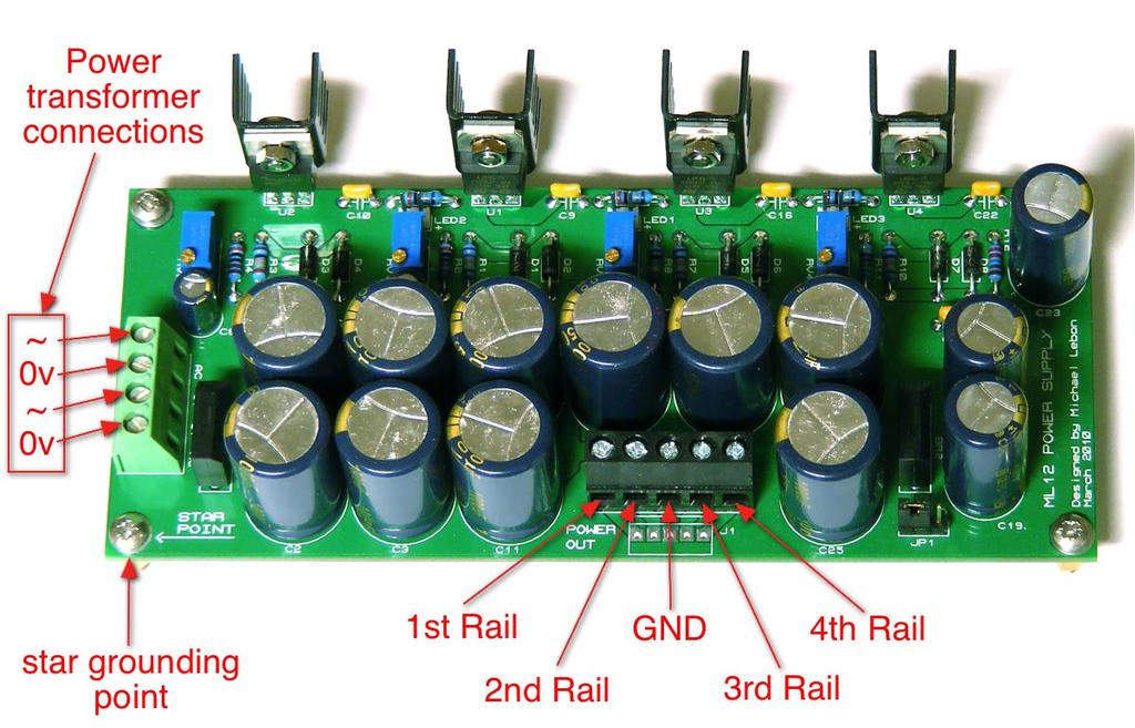
15 REFERENCE PICTURES Bare PSU PCB component side. PSU with heat sinks and optional 0.1 regulated output header. 15
16 ML12 Power Supply Unit - Schematic D7 +48V 3 U4 VI VO 2 BR2 ADJ 1 D8* R10 R12 C18 C19 C20 R11 C22 C23 C21* RV4 LED4 D JP1 JUMPER2 D5 C24 C25 T 3 U3 VI VO 2 Third Rail (POSITIVE) ADJ 1 D6 R7 R9 R8 C13 C14 C16 C17 C15 RV3 LED JP2 JUMPER2 3 U1 VI D1 VO 2 Second Rail (POSITIVE) BR1 ADJ 1 D2 R1 R5 C1 C3 C5 C9 C11 C7 RV1 LED1 RV2 C8 R6 C2 C4 C6 C10 C12 TR1 U2 D4 R3 LED2 ADJ R2 R4 1 SW1 2 VI VO 3 FU1 1A 120V AC D3 * Components needed only if U4 is LM317. Do not use if using TL783 as U4. First Rail (NEGATIVE) VSINE Designed by Michael Lebon - March 2010
17
ABC V1.0 ASSEMBLY IMPORTANT!
 ABC V1.0 ASSEMBLY Before starting this kit, prepare the following tools: Soldering iron (15-20W will do), flush cutters, no.2 hex screwdriver or allen key and phillips screwdriver. Also briefly go through
LITTLE NERD v1.1 Assembly Guide
 last update: 9. 3. 2016 LITTLE NERD v1.1 Assembly Guide bastl instruments.com INTRODUCTION This guide is for building Little Nerd module from Bastl Instruments. It is good to have basic soldering skills
Bill of Materials: PWM Stepper Motor Driver PART NO
 PWM Stepper Motor Driver PART NO. 2183816 Control a stepper motor using this circuit and a servo PWM signal from an R/C controller, arduino, or microcontroller. Onboard circuitry limits winding current,
LA502 Assembly guide Main PCB Resistors - (2)
") LA502 Assembly guide Safety warning The kits are main powered and use potentially lethal voltages. Under no circumstance should someone undertake the realisation of a kit unless he has full knowledge about
LA502 Assembly guide Safety warning The kits are main powered and use potentially lethal voltages. Under no circumstance should someone undertake the realisation of a kit unless he has full knowledge about
TS500 Assembly guide. Soldering. TS500 Assembly guide Main PCB 1. Diodes. Document revision 1.2 Last modification : 17/12/16
 TS500 Assembly guide Safety warning The kits are main powered and use potentially lethal voltages. Under no circumstance should someone undertake the realisation of a kit unless he has full knowledge about
Polyphase network kit
 Polyphase network kit 1. Introduction This polyphase network module is designed to be used with the QRP Labs receiver module kit. It takes as inputs, four phase audio from the Quadrature Sampling Detector
Total solder points: 101 Difficulty level: beginner advanced ELECTRONIC WATCHDOG K2655 ILLUSTRATED ASSEMBLY MANUAL
 Total solder points: 101 Difficulty level: beginner 1 2 3 4 5 advanced ELECTRONIC WATCHDOG K2655 Listens and scares intruders with realistic barking. ILLUSTRATED ASSEMBLY MANUAL H2655IP-2 Features & Specifications
Simple LFO Features. 2. Application. 3. Description. Simple and easy to build LFO module for Analog Synthesizers.
 Simple LFO. Simple and easy to build LFO module for Analog Synthesizers.. Features Square and Triangle waveforms (90 phase shifted) Dual range frequencies Frequency ranges from under Hz up to several khz
Penrose Quantizer Assembly Guide
 Penrose Quantizer Assembly Guide Schematic and BOM The schematic can be found here: www.sonic-potions.com/public/penrosequantizerschematic.pdf The BOM is available at google docs: Link to BOM Prepare the
Assembly and User Guide
 Assembly and User Guide AtariPunkr is an adjustable stepped tone generator. AtariPunkr provides hours of fun everyone! Powered by: 9V Battery Outputs: Mylar Speaker (Included) Stereo Output (3.5mm Jack)
MICROGRANNY v2.1 - Assembly Guide
 last update: 9. 5. 2017 MICROGRANNY v2.1 - Assembly Guide bastl-instruments.com INTRODUCTION Welcome to the assembly guide for the MicroGranny kit. MicroGranny is a monophonic granular sampler by Bastl
Power Supply Board. by Classic Valve Design for the Dynaco Mark-III with failsafe bias and balance
 Power Supply Board by Classic Valve Design for the Dynaco Mark-III with failsafe bias and balance Classic Valve Design assumes no responsibility for circuit or user damage from the use or misuse of these
SoftRock v6.0 Builder s Notes. May 22, 2006
 SoftRock v6.0 Builder s Notes May 22, 2006 Be sure to use a grounded tip soldering iron in building the v6.0 SoftRock circuit board. The soldering iron needs to have a small tip, (0.05-0.1 inch diameter),
Pacific Antenna Field Strength Indicator Kit
 Pacific Antenna Field Strength Indicator Kit Description The Field Strength Indicator kit from Pacific Antenna provides a visual way to monitor the presence and relative strength RF fields through the
Read This Page First
 Read This Page First If you are reading this you know the manuals are always available at QRPKITS.com. This is version 8.0 of the manual dated 4/27/2016. There is no need to print out the whole assembly
Pacific Antenna Wall Wart Tamer 2.0 Kit
 Pacific Antenna Wall Wart Tamer 2.0 Kit Description The Wall Wart Tamer lets you utilize those surplus computer and wall pack power supplies as a clean, adjustable voltage, DC power source for radios and
MP573 Assembly guide. Soldering. MP573 Assembly guide PCB split PCB split. Document revision 2.2 Last modification : 22/08/17
 MP573 Assembly guide Safety warning The kits are main powered and use potentially lethal voltages. Under no circumstance should someone undertake the realisation of a kit unless he has full knowledge about
Building the Toothpick Audio CW Filter
 Building the Toothpick Audio CW Filter Introduction The toothpick is a simple variable bandpass audio filter designed to compliment the Splinter QRPp Trans-Receiver. The filter also contains an audio amplifier
Pacific Antenna Easy Transmitter Kit
 Pacific Antenna Easy Transmitter Kit Introduction The Easy Transmitter kit from qrpkits.com provides a crystal controlled transmitter with VXO tuning. The circuit consists of a N3904 based crystal oscillator
Warm Tube Clock. Before we start, please make sure that you have all required parts that come for the main board :
 Warm Tube Clock Assembly Instructions for the main board Introduction Congratulations on your purchase of OSH Nixie Tube Clock. In this document you will see all steps you need to follow in order to successfully
FROM: Apply +15V to the HV SAMPLE terminal on the self-resonant board. Verify that the red LED, D6 (HV Charge) is illuminated on the display board.
 is illuminated on the display board.") The following document outlines the known errors and omissions in the minibrute DRSSTC design. These include both the book, DRSSTC: Building the Modern Day Tesla Coil minibrute Reference Design as well
The following document outlines the known errors and omissions in the minibrute DRSSTC design. These include both the book, DRSSTC: Building the Modern Day Tesla Coil minibrute Reference Design as well
KLIK v1.0 - Assembly Guide
 last update: 12. 7. 2017 KLIK v1.0 - Assembly Guide bastl-instruments.com INTRODUCTION Welcome to the assembly guide for the KLIK by BASTL INSTRUMENTS. Klik is a synchronisation device that enables you
Construction notes for the symmetrical 400 watt amplifier
 Construction notes for the symmetrical 400 watt amplifier Introduction The symmetrical amplifier is an update of one of my designs, which appeared in the Australian electronics magazine Silicon Chip in
5W Mono Amplifier Kit
 5W Mono Amplifier Kit Kit Construction Before you start assembling your kit there are a couple of important things you must do. FIRST read through these instructions entirely before you start construction
build info nonlinearcircuits
 It s 555 resonator build info nonlinearcircuits BOM BC547 10 npn marked n on PCB see notes BC557 10 pnp- marked p on PCB see notes 555 IC 5 TL072 2 TL074 1 power connector 0.156 1 Molex 3 pin 100k pots
Universal Flyback Driver
 Instruction Manual Eastern Voltage Research, LLC August 2010, Rev 2 1 http://www.easternvoltageresearch.com AGE DISCLAIMER THIS KIT IS AN ADVANCED, HIGH POWER SOLID STATE POWER DEVICE. IT IS INTENDED FOR
Instructions for Building the Pulsed Width Modulation Circuit. MC-12 (DC Motor Controller or PWM) From Electronic Light Inc. (revised kit 10/03/08)
 From Electronic Light Inc. (revised kit 10/03/08)") Instructions for Building the Pulsed Width Modulation Circuit MC-12 (DC Motor Controller or PWM) From Electronic Light Inc. (revised kit 10/03/08) Congratulations on your purchase of the MC-12 DC Motor
Instructions for Building the Pulsed Width Modulation Circuit MC-12 (DC Motor Controller or PWM) From Electronic Light Inc. (revised kit 10/03/08) Congratulations on your purchase of the MC-12 DC Motor
Bill of Materials: Metronome Kit PART NO
 Metronome Kit PART NO. 2168325 The metronome kit allows you to build your own working electronic metronome. Features include a small speaker, flashing LED, and the ability to switch between several different
KASTLE v1.5 - Assembly Guide
 last update: 14. 12. 2017 KASTLE v1.5 - Assembly Guide bastl-instruments.com INTRODUCTION Welcome to the assembly guide for the Kastle kit - mini modular synthesizer. It is suitable for beginners. It is
Laboratory PSU. Applications *Laboratories and test benches * Powering mobile radio equipment. * Precision charging of batteries
 0A. OV Laboratory PSU * Output voltage variable from 0 to +0V (Fine adjustment over V) * Variable current limit from 0 to OA * LED current limit indicator * Output short circuit protected Maximum 0. 5V
SoftRock v6.0 Builder s Notes. April 6, 2006
 SoftRock v6.0 Builder s Notes April 6, 006 Be sure to use a grounded tip soldering iron in building the v6.0 SoftRock circuit board. The soldering iron needs to have a small tip, (0.05-0. inch diameter),
Instructions for Building the Pulsed Width Modulation Circuit. MC-12 (DC Motor Controller or PWM) From Electronic Light Inc. (revised kit 5/08)
 From Electronic Light Inc. (revised kit 5/08)") Instructions for Building the Pulsed Width Modulation Circuit MC-12 (DC Motor Controller or PWM) From Electronic Light Inc. (revised kit 5/08) Using this circuit for a pulsed DC current to your cell. Do
Instructions for Building the Pulsed Width Modulation Circuit MC-12 (DC Motor Controller or PWM) From Electronic Light Inc. (revised kit 5/08) Using this circuit for a pulsed DC current to your cell. Do
Instructions for Building the Pulsed Width Modulation Circuit. MC-12 (DC Motor Controller or PWM) From Electronic Light Inc.
 From Electronic Light Inc.") Instructions for Building the Pulsed Width Modulation Circuit MC-2 (DC Motor Controller or PWM) From Electronic Light Inc. (revised 3/08) Using this circuit for a pulsed DC current to your cell, Do NOT
Instructions for Building the Pulsed Width Modulation Circuit MC-2 (DC Motor Controller or PWM) From Electronic Light Inc. (revised 3/08) Using this circuit for a pulsed DC current to your cell, Do NOT
DuoDrive Nixie Bargraph Kit
 Assembly Instructions And User Guide Nixie Bargraph Kit - 1 - REVISION HISTORY Issue Date Reason for Issue Number 1 12 December 2017 New document - 2 - 1. INTRODUCTION 1.1 About Nixie Bargraph Driver IN-9
EZ1290 Assembly Guide
 EZ190 Assembly Guide Capacitors This picture shows the different types of capacitors used and how they are symbolized and mounted on the PCB. Don t mess this up or bad things will happen!!! Electrolytic
S-Pixie QRP Kit. Student Manual. Revision V 1-0
 S-Pixie QRP Kit Student Manual Revision V 1-0 Introduction The Pixie 2 is a small, versatile radio transceiver that is very popular with QRP (low power) amateur radio operators the world over. It reflects
Ten Tec DDS Board Assembly Procedure
 05 May 2014 Ten Tec DDS Board Assembly Procedure You will find a photo of a completed board at the end of these instructions. Refer it whenever clarification is required. 1. AD9835 Attachment If you purchased
12V Dimmer Kit, version 2
 12V Dimmer Kit, version 2 User Manual Description The 12V Dimmer Kit V2 is an especially efficient PWM (pulse-width modulation) controller for 12V loads up to 60 watts. It features a single dial control
LED S METER CONSTRUCTION MANUAL. LED S meter Construction Manual Issue 1.0 Page 1
 LED S METER CONSTRUCTION MANUAL LED S meter Construction Manual Issue 1.0 Page 1 Important Please read before starting assembly STATIC PRECAUTION The LED S Meter kit contains components which can be damaged
16 Bit Micro Experimenter Assembly and Check out Instructions
 16 Bit Micro Experimenter Assembly and Check out Instructions The kit you purchased that includes PCB, schematic, complete parts list and these assembly instructions. A top picture of the complete assembly
D. Gillespie Designs. SCA-35 Capacitor Board. Installation Manual. D. Gillespie Designs with EFB TM
 D. Gillespie Designs SCA-5 Capacitor Board with EFB TM Installation Manual D. Gillespie Designs www.tronola.com Thank you for choosing our SCA-5 Capacitor Board with *EFB. We feel it is the single most
Construction Guide European Version
 Construction Guide European Version PCB This section describes how to build up the DRO-350 printed circuit board (PCB). The bare PCB is available for purchase on the order page. Static Protection Bare
Instructions for Building the Pulsed Width Modulation Circuit. MC-12 (DC Motor Controller or PWM) From Electronic Light Inc. (revised kit 8/08)
 From Electronic Light Inc. (revised kit 8/08)") Instructions for Building the Pulsed Width Modulation Circuit MC-12 (DC Motor Controller or PWM) From Electronic Light Inc. (revised kit 8/08) Using this circuit for a pulsed DC current to your cell. Do
Instructions for Building the Pulsed Width Modulation Circuit MC-12 (DC Motor Controller or PWM) From Electronic Light Inc. (revised kit 8/08) Using this circuit for a pulsed DC current to your cell. Do
Manual Version July 2007
 Manual Version 1.2 - July 2007 Page 1 Table of Contents Section1: M3 Phono Board Build...3 Phono Board Parts List...3 Preparation...4 Fitting the Valve Bases...6 Installing the Resistors...7 Starting the
The Tellun Corporation. TLN-863 Max Min Generator. User Guide, Rev Scott Juskiw The Tellun Corporation
 The Tellun Corporation TLN-863 Max Min Generator User Guide, Rev. 1.1 Scott Juskiw The Tellun Corporation scott@tellun.com TLN-863 User Guide Revision 1.1 May 26, 2008 1. Introduction The TLN-863 Max Min
PM124 Installation Instructions. See important note about revisions of this board on the last page.
 Marchand Electronics Inc. PO Box 473, Webster, NY 14580 Tel:(716) 872-0980 Fax:(716) 872-1960 info@marchandelec.com http://www.marchandelec.com (c)1997 Marchand Electronics Inc. PM124 Installation Instructions
nonlinearcircuits QUO/LPF build notes version 2 11 April 2014
 nonlinearcircuits QUO/LPF build notes version 2 11 April 2014 This circuit is based on the 4 pole LPF in Electronotes 41, tho has been subject to a number of tweaks and prods to bring it to where it is
Assembly and Installation Instructions for White Oak Audio Design TM-1001 LED board
 Thank you for purchasing White Oak Audio Design s TM-1001 Upgrade LED Light Board. White Oak Audio Design products are meticulously engineered and tested to ensure a direct drop in fit with your tuner.
LED Field Strength Indicator Kit
 LED Field Strength Indicator Kit Description The Field Strength Indicator kit from Qrpkits.com provides a visual way to monitor RF fields through the brightness of an LED. It will respond to RF fields
Switcher Assembly guide. Switcher Assembly guide 1. Soldering. 2. Switcher3 vs Switcher2. 3. PCB split.
 Safety warning The kits are main powered and use potentially lethal voltages. Under no circumstance should someone undertake the realisation of a kit unless he has full knowledge about safely handling
CV Arpeggiator Rev 1. Last updated
 CV Arpeggiator Rev Last updated 6--20 The CV Arpeggiator is a modular synth project used for creating arpeggios of control voltage. It utilizes a custom programmed PIC 6F685 micro controller. It includes
Circuit Board Assembly Instructions for Babuinobot 1.0
 Circuit Board Assembly Instructions for Babuinobot 1.0 Brett Nelson January 2010 1 Features Sensor4 input Sensor3 input Sensor2 input 5v power bus Sensor1 input Do not exceed 5v Ground power bus Programming
CW-ADD. Universal CW Adapter for SSB Transceivers. Assembly manual. Last updated: October 1,
 CW-ADD Universal CW Adapter for SSB Transceivers Assembly manual Last updated: October 1, 2017 ea3gcy@gmail.com Updates and news at: www.ea3gcy.com Thanks for building the Universal CW Adapter kit CW-ADD
TekBot Remote Control Receiver Board Construction
 TekBot Remote Control Receiver Board Construction Purpose This tutorial illustrates the procedure for construction of the Receiver board for the TekBot. A Guide to Soldering Many of you have soldered once
K8039 DMX CONTROLLED POWER DIMMER. Control a lamp or group of lamps trough a DMX signal. Suitable for resistive and mains voltage halogen lighting.
 DMX CONTROLLED POWER DIMMER K8039 Control a lamp or group of lamps trough a DMX signal. Suitable for resistive and mains voltage halogen lighting. Specifications control source: DMX-512, 3 pin XLR socket
Circuit Board Assembly Instructions
 Circuit Board Assembly Instructions This document walk you through the assembly of the Base4 Clock v1.2 - v1.3 circuit boards. Important note for kit buyers The color and appearance of the components may
PM24 Installation Instructions
 Marchand Electronics Inc. PO Box 473, Webster, NY 14580 Tel:(716) 872-0980 Fax:(716) 872-1960 info@marchandelec.com http://www.marchandelec.com (c)1997 Marchand Electronics Inc. PM24 Installation Instructions
Total solder points: 271 Difficulty level: beginner advanced. 2 x 15 LED STEREO VU METER K4306 ILLUSTRATED ASSEMBLY MANUAL
 Total solder points: 271 Difficulty level: beginner 1 2 3 4 5 advanced 2 x 15 LED STEREO VU METER K4306 For high precision audio level indication ILLUSTRATED ASSEMBLY MANUAL H4306IP-1 Features & Specifications
Model 333 Single Channel USB Chromatography Data System Relay ( Contact Closure ) Installation
 Installation") Remove the four screws holding the Model 333 A/D board in the stand-alone box. If the 333 is installed in a GC or HPLC, remove the four hex head screws from the outside of the instrument which secure the
Remove the four screws holding the Model 333 A/D board in the stand-alone box. If the 333 is installed in a GC or HPLC, remove the four hex head screws from the outside of the instrument which secure the
Starving Student II. Starving Student II. SS2 guide. Written By: 6L guides.diyaudio.com/ Page 1 of 24
 SS2 guide Written By: 6L6 2019 guides.diyaudio.com/ Page 1 of 24 INTRODUCTION This is a build guide for the hybrid headphone/pre-amplifier. You can buy a kit at the SSII product listing on the diyaudio
SoftRock v5.0 Builder s Notes. December 12, Building a QSD Kit
 SoftRock v5.0 Builder s Notes December 12, 2005 Building a QSD Kit Be sure to use a grounded tip soldering iron in building the QSD board. The soldering iron needs to have a small tip, (0.05-0.1 inch diameter),
FROM SCHEMATIC TO VEROBOARD
 FROM SCHEMATIC TO VEROBOARD The circuit of a bench amplifier utilising a LM386 linear (integrated circuit) IC and a few other components is used for this tutorial. The schematic is shown below: First a
Lightning Detector 1.0
 Lightning Detector 1.0 Instruction Manual Eastern Voltage Research, LLC January 2017, REV A 1 http://www.easternvoltageresearch.com SAFETY DISCLAIMER THIS KIT IS FOR HOBBY / NOVELTY USE ONLY. IT IS NOT
Main improvements are increased number of LEDs and therefore better temperature indication with one Celsius degree increments.
 LED Thermometer V2 (Fahrenheit/Celsius/±1 ) PART NO. 2244754 After completing this great starter kit, users will have a nice interactive LED thermometer. You will learn one principle how temperature can
Grounded Grid Plus Vacuum Tube Preamplifier User Manual. Analog Metric
 Grounded Grid Plus Vacuum Tube Preamplifier User Manual Analog Metric Page 2 INTRODUCTION This Grounded Grid Plus preamplifier provides enhanced performance out of the original Grounded Grid design. This
10 2 2,13,15,16,46 27, non-inductive ,26,
 HANDS-ON RADIO PARTS LIST (Thanks, John AF4WM and Steve AD7KR) Updated through Experiment 129 Quantities assume all parts available for re-use MAX QTY EXPERIMENT NOTES 1/4 WATT RESISTOR (All values are
Rangemaster Treble Booster Kit Building Manual
 Rangemaster Treble Booster Kit Building Manual Effect Pedal Kits: Rangemaster Treble Booster The Dallas Rangemaster is the most famous treble booster effect pedal, and it was the first pedal of its kind.
The Tellun Corporation. TLN-861 Dunsel. User Guide, Rev Scott Juskiw The Tellun Corporation
 The Tellun Corporation TLN-861 Dunsel User Guide, Rev. 1.0 Scott Juskiw The Tellun Corporation scott@tellun.com TLN-861 User Guide Revision 1.0 August 31, 2006 1. Introduction The TLN-861 Dunsel is a collection
Dual Digital Build Manual
 Dual Digital Build Manual Introduction This document is meant to aid you in assembling your Dual Digital Oscillator (DDO from now on). Some instructions may be a bit basic for advanced builders but I hope
Axis Fuzz Kit Building Manual
 Axis Fuzz Kit Building Manual Effect Pedal Kits: Axis Fuzz The Axis Fuzz Kit is based in the Roger Mayer Axis Fuzz, the effect pedal responsible for Jimi Hendrix sound in Axis Bold As Love. What else is
1217 AUDIOPHILE AMPLIFIER POWER SUPPLIER ±24V to ± 80V, 5-20A
 Description Quasar kit No.1217 is part of a new line of constructions which combined form a full stereo system. The line consists of the following KITS Quasar kit No.1214 6 inputs stereo selector Quasar
The Tellun Corporation. TLN-442 Voltage Controlled Lowpass Filter. User Guide, Rev Scott Juskiw The Tellun Corporation
 The Tellun Corporation TLN-442 Voltage Controlled Lowpass Filter User Guide, Rev. 1.1 Scott Juskiw The Tellun Corporation scott@tellun.com TLN-442 User Guide Revision 1.1 March 15, 2003 Introduction The
the DON classics U76 (blue face - rev A) ASSEMBLY GUIDE REV: 1:04
 ASSEMBLY GUIDE REV: 1:04") the DON classics www.thedonclassics.com U76 (blue face - rev A) ASSEMBLY GUIDE REV: 1:04 QUICK ASSEMBLY GUIDE 9 STEPS TO COMPRESSOR HEAVEN! 1. 2. 3. 4. 5. 6. 7. 8. 9. Solder parts on PCB Wire pots Solder
the DON classics www.thedonclassics.com U76 (blue face - rev A) ASSEMBLY GUIDE REV: 1:04 QUICK ASSEMBLY GUIDE 9 STEPS TO COMPRESSOR HEAVEN! 1. 2. 3. 4. 5. 6. 7. 8. 9. Solder parts on PCB Wire pots Solder
Simple Renard 8 Channel Controller
 Simple Renard 8 Channel Controller January 2013 Version 1.00 Board Page 1 of 28 Table of Contents TABLE OF CONTENTS...2 OVERVIEW...3 CONSTRUCTION...3 BASIC TOOLS...3 Soldering Iron...3 Solder...4 Side
πλ² Synthesizer Manual for Assembly Kit Features 2 Oscillators 4 Waveforms 32 Presets 32 User presets
 πλ² Synthesizer Manual for Assembly Kit Features 2 Oscillators 4 Waveforms 32 Presets 32 User presets Specifications Power supply: +5V DC/50mA Dimensions: 100 x 100 x 23mm Congratulations on purchasing
Electric Druid 4 second Digital Delay Project
 Electric Druid 4 second Digital Delay Project Overview! 2 Build Instructions! 2 Populate the PCB! 2 Resistors! 2 Cup of tea and soldering check! 3 Power protection diode! 4 Ground link wire! 4 IC sockets!
STEP 0 Prepare the Materials.
 How to Build a Germanium Fuzz Guitar Effect. This document will guide you to build and test your Germanium Fuzz guitar pedal. With all the materials on hand, it takes around 2-4 hours to build it. Try
DIY Function Generator XR2206
 DIY Function Generator XR2206 20Hz 100KHz http://radiohobbystore.com Components List: Resistors: R1, R2 1% Metal Film 5K1 R4 1% Metal Film 10K R5 1% Metal Film 3K R10 5% Carbon Film 10R R3, R9 Potentiometer
VC Divider Assembly manual
 1 VC Divider Assembly manual Thank you for your purchase of the SSSR Labs VC Divider DIY Kit! This manual will help you assemble the VC Divider quickly and easily. Follow the instructions! As you may know,
TLN-428 Voltage Controlled State Variable Filter
 The Tellun Corporation TLN-428 Voltage Controlled State Variable Filter User Guide, Rev. 1.1 Scott Juskiw The Tellun Corporation scott@tellun.com TLN-428 User Guide Revision 1.1 March 16, 2003 Introduction
Evaluation Board: H-Bridge Motor Drivers For DC Brush Motors
 ROHM Motor Driver IC Solutions Evaluation Board: H-Bridge Motor Drivers For DC Brush Motors BD6212FP, BD6222FP, BD6232FP (2A / 5.5V, 15V, 32V) No.0000000012 Introduction This application note will provide
Universal Flyback Driver
 Universal Flyback Driver 2.0 Instruction Manual Eastern Voltage Research, LLC May 2012, Rev - 1 http://www.easternvoltageresearch.com AGE DISCLAIMER THIS KIT IS AN ADVANCED, HIGH POWER SOLID STATE POWER
Stand Alone VXO (SAVXO) Assembly Manual Manual Version 1.0B_
 Assembly Manual Manual Version 1.0B_") Stand Alone VXO (SAVXO) Assembly Manual Manual Version.0B_0-6-0 Designed by: Jim Kortge, K8IQY Kitted & Sold by: 4 State QRP Group Copyright: 0 Forward Thank you for purchasing a 4 State QRP Group Stand
Stand Alone VXO (SAVXO) Assembly Manual Manual Version.0B_0-6-0 Designed by: Jim Kortge, K8IQY Kitted & Sold by: 4 State QRP Group Copyright: 0 Forward Thank you for purchasing a 4 State QRP Group Stand
12kHz LIF Converter V2.43 9Mhz version
 12kHz LIF Converter V2.43 9Mhz version Please Note: This document supersedes all previously released documents and drawings on the LIF subject. This is the latest and most up-to-date document at this time.
Pacific Antenna - Easy TR Switch
 Pacific Antenna - Easy TR Switch Kit Description The Easy TR Switch is an RF sensing switch that can be used to switch an antenna between a receiver and transmitter. It also has a second switched pair
Easy Transmitter. Support ETX_REV5_Manual V2.7 Revised
 Easy Transmitter Introduction The Easy Transmitter kit from qrpkits.com provides a basic, crystal controlled transmitter with VXO tuning to provide a small tuning range around the crystal frequency. It
Build Your Own Clone Crown Jewel Kit Instructions
 Build Your Own Clone Crown Jewel Kit Instructions Warranty: BYOC, Inc. guarantees that your kit will be complete and that all parts and components will arrive as described, functioning and free of defect.
CPC9909EB. Hi-Brightness, Off-Line LED Driver Evaluation Board User s Guide INTEGRATED CIRCUITS DIVISION
 CPC9909EB Hi-Brightness, Off-Line LED Driver Evaluation Board User s Guide Specifications Parameter Min Typ Max Unit Input Voltage AC - - 265 V rms DC 15-375 V DC Load Current - - 350 ma Efficiency - 90
V. 3. Assembly Guide. ShortWave Receiver Kit Double Super 10.7Mhz /455Khz SSB/CW/AM 5.9 Mhz to 8.1 Nominal. SW-Receiver
 Assembly Guide V. 3 JUNIOR 1 ShortWave Receiver Kit Double Super 10.7Mhz /455Khz SSB/CW/AM 5.9 Mhz to 8.1 Nominal SW-Receiver Table of contents PAGE TITLE PAGE JUNIOR 1 General Description I1 JUNIOR 1
UK-electronic 2008/13
 UK-electronic 2008/13 Assembly manual for Kit BOR Clone Rev. 1.22 (2N7000) Ver. 2014 Page 3...Bill of material Page 4..5...soldering the pcb Page 5...pcb layout top Page 6...wiring diagram Page 7..8...enclosure,
Beta-test ED1 PCB installed in I0CG s K1
 K1 SSB Modification (Ed.2) This description provides the receiver (RX) modifications, assembly, alignment and operation as a first step. In a second step you can add the remaining transmitter (TX) modifications,
R*S Stereo Mixer V1.2
 R*S Stereo Mixer V1.2 The Random*Source Equal Power Stereo-Mixer is a voltage controlled stereo mixer / panner / VCA based on 4 high-end THAT2180 blackmer VCAs, designed to emulate the behavior of Serge
Congratulations on your purchase of the SparkFun Arduino ProtoShield Kit!
 Congratulations on your purchase of the SparkFun Arduino ProtoShield Kit! Well, now what? The focus of this guide is to aid you in turning that box of parts in front of you into a fully functional prototyping
FREEKOUT FX TYPE: Ring Modulator Based on the EHX Frequency Analyzer 2015 madbeanpedals
 FREEKOUT FX TYPE: Ring Modulator Based on the EHX Frequency Analyzer 2015 madbeanpedals 2.3 W x 3.025 H This project requires an 18v 100mA (or more) center tip negative power supply. I recommend the Dunlop
Total solder points: Difficulty level: beginner advanced 0 TO 60 HOUR START / STOP TIMER K6200 ILLUSTRATED ASSEMBLY MANUAL
 Total solder points: 96 + 43 Difficulty level: beginner 1 2 3 4 5 advanced 0 TO 60 HOUR START / STOP TIMER K6200 Broad range mains operated start / stop timer. ILLUSTRATED ASSEMBLY MANUAL H6200IP-1 VELLEMAN
V6.2 SoftRock Lite Builder s Notes. November 17, 2006
 V6.2 SoftRock Lite Builder s Notes November 17, 2006 Be sure to use a grounded tip soldering iron in building the v6.2 SoftRock circuit board. The soldering iron needs to have a small tip, (0.05-0.1 inch
HT-1A Dual Band CW QRP Transceiver. Kit Building Instructions
 HT-A Dual Band CW QRP Transceiver Kit Building Instructions Rev B, July 8, 08 Designed by BD4RG Exclusively distributed by CRKITS.COM and its worldwide distributors Join the group http://groups.io/g/crkits
ZLED7020KIT-D1 Demo Kit Description
 ZLED7020KIT-D Demo Kit Description Important Notice Restrictions in Use IDT s ZLED7020KIT-D Demo Kit hardware is designed for ZLED7020 demonstration, evaluation, laboratory setup, and module development
Never power this piano with anything other than a standard 9V battery!
 Welcome to the exciting world of Digital Electronics! Who is this kit intended for? This kit is intended for anyone from ages 13 and above and assumes no previous knowledge in the field of hobby electronics.
DEMO MANUAL DC2172A. LTC7138 High Efficiency, High V IN, Step-Down Regulator. Description. Performance Summary
 DEMO MANUAL DC7A Description Demonstration circuit 7A is a high input voltage, 4mA step-down regulator featuring the LTC78. The output of the regulator can be programmed for either 5V,.V or.8v with on-board