Operating Manual. isolate501
|
|
|
- Marianna Garrett
- 5 years ago
- Views:
Transcription


1 Operating Manual isolate501
2 Document Number (See Last Page for Revision Details). Copyright Extronics Ltd, 2015 Page 2 of 21
3 Contents 1 Introduction Safety Information and Notes Storage of this Manual Special Conditions for Safe Use ATEX/IECEx List of Notes Installation and Setting-to-Work Input / Output parameters isolate501 Mounting and Earthing RF Connections Connection to a transmitter Example of RF threshold power calculation Connection to an antenna Example Example Intended Purpose Usage Transportation and Storage Authorized Persons Cleaning and Maintenance Safety Precautions Cleaning and Maintenance Intervals Aggressive substances and environments Exposure to external stresses Technical Data Label Drawing Manual Revision History Page 3 of 21
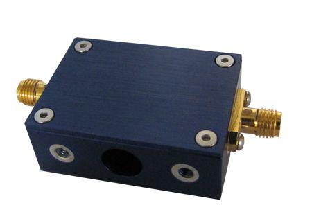
4 1 Introduction The isolate501 is an ATEX and IECEx approved RF galvanic isolator. For Zone 0/1 and mining applications, the isolate501 must be installed in the safe area. For Zone 2/22 applications, the isolate501 must be mounted in an IECEx/ATEX approved Ex n or Ex e enclosure with minimum IP54 rating while situated in hazardous gas atmospheres and must be mounted in an IECEx/ATEX approved Ex e enclosure with minimum IP54 rating while situated in hazardous dust atmospheres. The isolate501 galvanically isolates circuits in the hazardous area from potentially incendive faults using the intrinsic safety concept. When the isolate501 is connected to source equipment with Um 250V, it blocks DC, low-frequency AC and transient faults from appearing at the output terminal. The isolate501 will allow RF signals at frequencies within its wide pass-band (120MHz - 8GHz) to pass through to its output; these RF signals are incapable of causing ignition if their power level is within that specified in IEC :2011 Table 4. The galvanically isolated RF output of the isolate501 allows users to use nonhazardous area certified antennas* with their wireless hardware, such as the Extronics iant200 range of high quality rugged outdoor antennas. * Antennas not listed in the Extronics range must be assessed by the user to ensure that they meet the requirements for the installation of equipment in hazardous areas. Page 4 of 21
5 2 Safety Information and Notes 2.1 Storage of this Manual Keep this user manual safe and in the vicinity of the device. All persons who have to work on or with the device should be advised on where the manual is stored. 2.2 Special Conditions for Safe Use ATEX/IECEx The RF power input to the device must be limited to defined power levels dependent on the Equipment/Gas Group: Maximum safe input power, defined as in normal operation without user-settable software limits, and must include antenna gain consideration. Group I Group IIC Group IIB Group IIA Group III 6.0W (37.7 dbm) 2.0W (33 dbm) 3.5W (35.4 dbm) 6.0W (37.7 dbm) 6.0W (37.7 dbm) Page 5 of 21
6 The product must be mounted such that it is earthed before use in accordance with clause 15 in IEC :2011. The product shall be mounted in an IECEx/ATEX approved Ex n or Ex e enclosure with minimum IP54 rating while situated in hazardous gas atmospheres. The product shall be mounted in an IECEx/ATEX approved Ex e enclosure with minimum IP54 rating while situated in hazardous dust atmospheres. No live connections or disconnections of connectors must be made on the product while situated in hazardous area. The product must only be situated in the safe area when providing ia output into mining M1 area. Page 6 of 21
7 2.3 List of Notes The notes supplied in this chapter provide information on the following. Danger / Warning. o Possible hazard to life or health. Caution o Possible damage to property. Important o Possible damage to enclosure, device or associated equipment. Information o Warning! Notes on the optimum use of the device For Zone 0/1 and mining applications, the isolate501 must only be installed in the safe area. For Zone 2/22 applications, the isolate501 must be mounted in an IECEx/ATEX approved Ex n or Ex e enclosure with minimum IP54 rating while situated in hazardous gas atmospheres and in an IECEx/ATEX approved Ex e enclosure with minimum IP54 rating while situated in hazardous dust atmospheres. Warning! The RF threshold power must be limited to the levels defined in IEC :2011 Table 4; the isolate501 does not provide any inband RF power limitation. See section for details. Warning! To maintain safe operation, the isolate501 MUST be earthed. Refer to Section 3.2 for details. Warning! The antennas connected to the isolate501 must be installed in accordance with the earthing requirements of IEC :2014 clause Warning! The isolate501 does not contain any user-serviceable parts. Any attempt to open the unit may render it unsafe and will void the warranty. Page 7 of 21
8 3 Installation and Setting-to-Work 3.1 Input / Output parameters The isolate501 has the following input/output parameters: U m =250V rms RF threshold Output Power = Effective RF Transmitter Power Input into the isolate501, multiplied by the antenna gain. The maximum permitted RF Threshold Output Power is dependent upon the Equipment Group in which the antenna is located, as defined in the following table. See section 3.4 for further details. ATEX/IECEx Equipment Group Maximum RF Threshold Power (Watts) Maximum RF Threshold Power (dbm) Mining Group I Gas Group IIA Gas Group IIB Gas Group IIC 2 33 Dust Group III Table 1: Maximum permitted RF Threshold Power Page 8 of 21
9 3.2 isolate501 Mounting and Earthing Warning! For Zone 0/1 and mining applications, the isolate501 must only be installed in the safe area. For Zone 2/22 applications, the isolate501 must be mounted in an IECEx/ATEX approved Ex n or Ex e enclosure with minimum IP54 rating while situated in hazardous gas atmospheres and in an IECEx/ATEX approved Ex e enclosure with minimum IP54 rating while situated in hazardous dust atmospheres. Warning! To maintain safe operation, the isolate501 MUST be earthed - see Figure 1. Page 9 of 21
10 Figure 1: Earthing and Mounting of isolate501 Page 10 of 21
11 Figure 2: isolate501 Dimensions Page 11 of 21
12 3.3 RF Connections The isolate501 is fitted with two SMA female connectors, one at each end. The isolate501 is a totally bi-directional device, and therefore either connector can function as the input or output. 3.4 Connection to a transmitter The isolate501 may be connected to any radio transmitter operating within its passband. It is the responsibility of the installer to ensure that the following requirements are met: 1. The RF threshold power radiated from the antenna must be limited to the levels shown in Table 1. The calculation of this should take into account the power output of the transmitter (as specified by the manufacturer in normal operation) and the gain of the antenna. It is permissible to consider losses in the cable in this calculation. 2. It is permissible for the maximum power output of the transmitter to be limited by a software setting, but it must not be possible for the end-user to override this. 3. Consideration of fault conditions in the transmitter is not necessary when calculating RF threshold power. The transmitter s maximum RF output power should be taken from the transmitter manufacturer s datasheet in normal operation, i.e. the maximum value of RF output power than can be set by the user. Page 12 of 21
13 3.4.1 Example of RF threshold power calculation The following example shows how the RF threshold power may be calculated: Maximum transmitter output power (from transmitter datasheet) = 20dBm (100mW) Coaxial cable loss = 2dB Antenna gain = 5dBi Threshold power = 20dBm 2dB + 5dBi Threshold power = 23dBm (200mW) 3.5 Connection to an antenna Warning! The antennas connected to the isolate501 must be installed in accordance with the earthing requirements of IEC :2014 clause Example 1 The conductive parts of the antenna must be isolated by at least 500Vrms from nearby conductive structures, to prevent hazardous earth currents from flowing in the coaxial cable. It is the responsibility of the installer to perform the necessary tests to verify this. Note: As the isolate501 must be earthed, the return path of the RF output connector will also be at earth potential. Therefore the verification of isolation of the antenna from earth must only be carried out when the antenna and isolate501 are not connected. Page 13 of 21
14 3.5.2 Example 2 When the isolate501 is installed inside an earthed enclosure, which has a single connection to earth, and the antennas are mounted to this enclosure, the antennas do not require 500V isolation from earth (as it may be earthed through the enclosure to the single earth point along with the isolate501) For more guidance consult IEC :2014 clause Page 14 of 21
15 Page 15 of 21 Figure 3: Electrical Installation
16 4 Intended Purpose Usage Important Before setting the units to work, read the technical documentation carefully. Important The latest version of the technical documentation or the corresponding technical supplements is valid in each case. The isolate501 is built using modern components and is extremely reliable in operation; however it must only be used for its intended purpose. Please note that the intended purpose also includes compliance with the instructions issued by the manufacturer for installation, setting up and service. Any other use is regarded as conflicting with the intended purpose. The manufacturer is not liable for any subsequent damage resulting from such inadmissible use. The user bears the sole risk in such cases. 4.1 Transportation and Storage All isolate501 devices must be so transported and stored that they are not subjected to any excessive mechanical stresses. 4.2 Authorized Persons Only persons trained for the purpose are authorized to handle the isolate501; they must be familiar with the unit and must be aware of the Page 16 of 21
17 regulation and provisions required for explosion protection as well as the relevant accident prevention regulations. 4.3 Cleaning and Maintenance The isolate501 and all its components require no maintenance. All work on the isolate501 by personnel who are not expressly qualified for such activities will cause the Ex approval and the guarantee to become void. 4.4 Safety Precautions Important For the installation, maintenance and cleaning of the units, it is absolutely necessary to observe the applicable regulations and provisions concerned with explosion protection (IEC ), as well as the Accident Prevention Regulations. 4.5 Cleaning and Maintenance Intervals The cleaning intervals depend on the environment where the system is installed. 4.6 Aggressive substances and environments The isolate501 is not designed to come into contact with aggressive substances or environments, please be aware that additional protection may be required. Page 17 of 21
18 4.7 Exposure to external stresses The isolate501 is not designed to be subjected to excessive stresses e.g. vibration, heat, impact. Additional protection is required to protect against these external stresses. The isolate501 will require additional protection if it is installed in a location where it may be subjected to damage. Page 18 of 21
19 5 Technical Data Certification Type Maximum Input / Output Power Enclosure Material Environmental Dimensions (w x h x d) Weight RF Connections Ex na [Ex ia Ga] IIC T6 Gc Ex ic [Ex ia Da] IIIC T85 C Dc [Ex ia Ma] I II 3 (1) G D I (M1) ATEX/IECEx Maximum RF Maximum RF Equipment Threshold Power Threshold Power Group (Watts) (dbm) Mining Group I Gas Group IIA Gas Group IIB Gas Group IIC 2 33 Dust Group III Aluminium with chromate finish Ambient temperature: -40ºC to +80ºC Relative humidity; 0 to 95%, non-condensing 38.4 x 28 x 14.4 mm (57 mm including SMA connectors) 37g SMA Female Certification TRAC15ATEX0050X, IECEx TRC X 1 Please note that it is the customers responsibility to ensure the maximum values for RF Threshold power as per Table 4.0 of IEC :2011 are not exceeded. The maximum RF output of the wireless transmitter and antenna gain must be taken into account when installing equipment. Refer to manual for full details. Page 19 of 21

20 6 Label Drawing Where xxxx = Notified Body Number Page 20 of 21
21 7 Manual Revision History Revision Description Date By 1.0 Initial release of manual 29/09/2015 DC Page 21 of 21
iant200 iant212 iant213 iant214 iant215 iant216 iant217 iant218 iant219 iant220 iant221 iant222 Operating Manual iant2xx Series of Antennas
 iant200 iant212 iant213 iant214 iant215 iant216 iant217 iant218 iant219 iant220 iant221 iant222 Operating Manual iant2xx Series of Antennas This page is intentionally left blank. Document Number 403449
Installation & Operating Manual. iwap202
 Installation & Operating Manual iwap202 This page is intentionally left blank. Document Number 409345 (based on 407655) (See Last Page for Revision Details) For warranty information, refer to Terms and
Safety Manual. Omni-ID UHF Tags
 Safety Manual Omni-ID UHF Tags This page is intentionally left blank. Document Number 330556 (See Last Page for Revision Details) 2012 Extronics Limited. This document is Copyright Extronics limited. Extronics
FM Safety Manual. Omni-ID UHF Tags
 FM Safety Manual Omni-ID UHF Tags This page is intentionally left blank. Document Number 334169 (See Last Page for Revision Details) 2012 Extronics Limited. This document is Copyright Extronics limited.
Solexy USA, LLC International Blvd Cincinnati, Ohio Phone: Fax:
 OVERVIEW The Solexy RX series explosion proof and intrinsically safe antenna coupler is an integrated protection device that facilitates non-ex certified radio antenna installation in hazardous areas.
GETTING STARTED GUIDE NI khz to 100 MHz, 50 Ω, AC Coupled RF Receiver Module
 GETTING STARTED GUIDE NI 9770 30 khz to 100 MHz, 50 Ω, AC Coupled RF Receiver Module This document explains how to connect to the NI 9770. Note Before you begin, complete the software and hardware installation
Certificate of Compliance
 Certificate of Compliance Certificate: 70163240 (166720) Issued to: WIKA Alexander Wiegand SE & Co. KG Alexander-Wiegand-Str 30 Klingenberg, Bayern 63911 GERMANY Attention: Harald Gollas The products listed
Analog Universal Module HART for Zone 2 Series 9468/33
 > 8 channels can be adjusted individually as analog inputs or outputs > Intrinsically safe inputs/outputs Ex ia > For 0/4 20 ma + HART signals > Line fault monitoring per channel > Diagnostics based on
iant101 Zone 1 Omni Directional Antenna
 iant101 Zone 1 Omni Directional Antenna External Antenna offering increased flexibility for positioning and greatly enhanced RF Propagation. ATEX Ex t IIIC T85 C Db IECEx Ex t IIIC T85 C Db -40 C to 60
IECEx Certificate of Conformity
 INTERNATIONAL ELECTROTECHNICAL COMMISSION IEC Certification Scheme for Explosive Atmospheres for rules and details of the IECEx Scheme visit www.iecex.com Certificate No.: Certificate history: Issue No.
GETTING STARTED GUIDE NI AI, ±10 V, 24 Bit, 50 ks/s/ch Simultaneous
 GETTING STARTED GUIDE NI 9239 4 AI, ±10 V, 24 Bit, 50 ks/s/ch Simultaneous This document explains how to connect to the NI 9239. Note Before you begin, complete the software and hardware installation procedures
BAR-ANT-N-N-EX. Antenna barrier for the hazardous area. Data sheet. 1 Description
 BAR--N-N-EX Antenna barrier for the hazardous area Data sheet 060_en_00 PHOENIX CONTACT 05-06-0 Description Using an antenna barrier, you can execute HF outputs of wireless modules with intrinsic safety.
RX Series UL Listed Explosion Proof Antenna Coupler For Hazardous Area Applications Installation & Operation Manual (IOM)
") OVERVIEW The Solexy RX explosion proof antenna coupler is an integrated protection device that facilitates radio antenna installation in hazardous areas. The patented (7,057,577) RX coupler features a
OVERVIEW The Solexy RX explosion proof antenna coupler is an integrated protection device that facilitates radio antenna installation in hazardous areas. The patented (7,057,577) RX coupler features a
Making Safe Waves in Hazardous Areas
 Making Safe Waves in Hazardous Areas A Wireless White Paper Wireless Vision Engineering Tracking Author: John Hartley Managing Director - Extronics Limited October 2014 Making Safe Waves in Hazardous Areas
Temperature Input Module for Zone 1 Series 9482/32
 www.stahl.de > 8 channels for temperature sensors > Intrinsically safe inputs Ex ia > For Pt-, Ni- and Cu-resistance temperature detectors according to DIN, IEC and GOST in 2-, 3- and 4-wire circuits >
Isolators A3/1. Vibration Transducer Supply Unit Series
 > For vibration, acceleration and speed sensors in 2- and 3-wire design > Space-saving dual-channel version > Signal frequencies up to 50 khz > Easy setting by means of front-side rotary switch > Galvanic
GETTING STARTED GUIDE NI AI, ±60 V, 24 Bit, 1 ks/s/ch Simultaneous
 GETTING STARTED GUIDE NI 9228 8 AI, ±60 V, 24 Bit, 1 ks/s/ch Simultaneous This document explains how to connect to the NI 9228. Note Before you begin, complete the software and hardware installation procedures
2-WIRE UNIVERSAL TEMPERATURE TRANSMITTER
 SAFE INSTALLATION MANUAL (FM APPROVAL) -WIRE UNIVERSAL TEMPERATURE TRANSMITTER (HART communication, intrinsically safe/explosion-proof) MODEL B6U/B6U-B BEFORE USE... SAFETY PRECAUTIONS This manual describes
INSTRUCTION MANUAL (ATEX / IECEx)
") INSTRUCTION MANUAL (ATEX / IECEx) STExS1 & STExS2 Sounder For use in Flammable Gas and Dust Atmospheres 1) Warnings DO NOT OPEN WHEN AN EXPLOSIVE ATMOSPHERE IS PRESENT POTENTIAL ELECTROSTATIC CHARGING
INSTRUCTION MANUAL (ATEX / IECEx) STExS1 & STExS2 Sounder For use in Flammable Gas and Dust Atmospheres 1) Warnings DO NOT OPEN WHEN AN EXPLOSIVE ATMOSPHERE IS PRESENT POTENTIAL ELECTROSTATIC CHARGING
GETTING STARTED GUIDE NI AI, ±5 V, 24 Bit, 51.2 ks/s/ch Simultaneous, AC/DC Coupling, IEPE AC Coupling
 GETTING STARTED GUIDE NI 9234 4 AI, ±5 V, 24 Bit, 51.2 ks/s/ch Simultaneous, AC/DC Coupling, IEPE AC Coupling This document explains how to connect to the NI 9234. Note Before you begin, complete the software
Digital Input Output Module 24 V for Ex n Zone 2 Series 9472/35
 www.stahl.de > 16 channels can be adjusted in pairs as digital inputs or outputs > Suitable for NAMUR proximity switches, 3-wire PNP proximity switches, contacts and solenoid valves (24 V / 0.5 A). > Up
IECEx Hazardous Area Approvals Fisher FIELDVUE DVC6200 Series Digital Valve Controllers
 Instruction Manual Supplement DVC6200 Digital Valve Controllers IECEx Hazardous Area Approvals Fisher FIELDVUE DVC6200 Series Digital Valve Controllers SIS Hazardous Area Approvals and Special Instructions
GETTING STARTED GUIDE NI AI Differential/32 AI Single-Ended, ±200 mv to ±10 V, 16 Bit, 250 ks/s Aggregate, Fuel-Cell Measurements
 GETTING STARTED GUIDE NI 9206 16 AI Differential/32 AI Single-Ended, ±200 mv to ±10 V, 16 Bit, 250 ks/s Aggregate, Fuel-Cell Measurements This document explains how to connect to the NI 9206. Note Before
Specifications. Specifications. Transfer Characteristics Accuracy at 20 C (68 F) Temperature Drift
 Temperature Drift") Appendix A Specifications 1797-IE8 and -IE8NF Input Modules Specifications Number of Inputs IS Input Type IS Module Type Resolution Transfer Characteristics Accuracy at 20 C (68 F) Temperature Drift Functional
Appendix A Specifications 1797-IE8 and -IE8NF Input Modules Specifications Number of Inputs IS Input Type IS Module Type Resolution Transfer Characteristics Accuracy at 20 C (68 F) Temperature Drift Functional
Binary Output without Power Supply Series 9176
 Binary Output without Power Supply Series 9176 > For intrinsically safe operation of Ex i solenoid valves, indicators and horns > Power supply by control circuit, loop powered > Intrinsically safe output
Isolators A3/1. Ex i Power Supply Field Circuit Ex i Series
 > Intrinsically safe output [Ex ib] IIC/IIB > Stable output voltage > Galvanic isolation between output and power supply > Power supply or 85... 230 V AC > Compact design www.stahl.de 07673E00 Basic function:
Digital Input Output Module for Zone 2 Series 9470/33
 www.stahl.de > 16 channels can be adjusted in pairs as digital input or output > Intrinsically safe inputs/outputs Ex ia > For contacts, NAMUR proximity switches and low-power solenoid valves > Up to 8
Isolators A3/1. Transmitter Supply Unit Field Circuit Ex i Series 9160
 Series 9160 > Intrinsically safe input [Ex ia] IIC > Galvanic isolation between input, output and power supply > For use up to SIL 2, special version up to SIL 3 (IEC 61508) > High accuracy www.stahl.de
Analog Input Module HART Ex i / I.S. Inputs, Channels Type 9461/
 > 4 channels for 2-wire HART transmitters and 4 channels for 4-wire HART transmitters > Intrinsically safe inputs Ex ia IIC > Galvanic separation between inputs and system > Open-circuit and short-circuit
Isolators A3/1. Transmitter Supply Unit Field Circuit Ex i Series 9160 Rev. F
 Series 9160 Rev. F > Intrinsically safe input [Ex ia] IIC > Galvanic isolation between input, output and power supply > For use up to SIL 2, special version up to SIL 3 (IEC 61508) > High accuracy www.stahl.de
ORiNOCO AP-4000MR-LR and AP-4900MR-LR Access Points Safety and Regulatory Compliance Information
 IMPORTANT! Visit http://support.proxim.com for the latest safety and regulatory compliance information for this product. ORiNOCO AP-4000MR-LR and AP-4900MR-LR Access Points Safety and Regulatory Compliance
User manual. Load cell with one built in amplifier KOSD-FA KIMD-FA KEND-FA Load cell with two built in amplifiers KOSD-FAD KIMD-FAD KEND-FAD
 User manual Load cell with one built in amplifier KOSD-FA KIMD-FA KEND-FA Load cell with two built in amplifiers KOSD-FAD KIMD-FAD KEND-FAD Contents Precautions Intended use General 1 Specification 3
OPTIWAVE 7300 C Supplementary instructions
 OPTIWAVE 7300 C Supplementary instructions Radar (FMCW) Level Transmitter for agitated liquids in process applications Supplementary Instructions for ATEX applications KROHNE CONTENTS OPTIWAVE 7300 C General
PRODUCT SPECIFICATION AND MODEL SELECTION GUIDE
 XYR 5000 Wireless Temperature Transmitters WT530 34-XY-03-02 09/2006 PRODUCT SPECIFICATION AND MODEL SELECTION GUIDE Function The WT530 Temperature Transmitter is part of the XYR 5000 family of wireless
Single-Channel Safety Barriers with Electronic Current Limitation Series 9004
 Single-Channel Safety Barriers with Electronic Current Limitation > Broad product range for all standard applications in the world of automation > Flexible and space saving > Time saving installation due
Wireless Dual Discrete Input Transmitter Series XYR 5000, Model WW59x Specifications - Americas
 Wireless Dual Discrete Input Transmitter Series XYR 5000, Model WW59x Specifications - Americas 34-XY-03-12 February 2008 Function The WW59x Dual Discrete Input Field Transmitter is part of the XYR 5000
Isolating Repeater Input Series 9163
 > For 4-wire HART transmitters and voltage sources > Intrinsically safe input [Ex ia] IIC > Galvanic isolation between input, output and power supply > For use up to SIL 2 (IEC 61508) > High accuracy www.stahl.de
Pressure transmitters MBS 4201, MBS 4251, MBS 4701 and MBS 4751
 060R9345 Instructions Pressure transmitters MBS 4201, MBS 4251, MBS 4701 and MBS 4751 Content Page 1 Description/application 2 Identification 3 Specifications 4 Safety instructions 5 Installation/dimensions
Isolators A3/1.
 > Compact limit value switch with 2 configurable limiting values and 4... 20 ma output > Suitable for 2-, 3-wire transmitters, 2-wire HART transmitters and ma sources > Intrinsically safe input [Ex ia]
User manual. Load cell with one built in amplifier KOSD-FA KIMD-FA KEND-FA Load cell with two built in amplifiers KOSD-FAD KIMD-FAD KEND-FAD
 User manual Load cell with one built in amplifier KOSD-FA KIMD-FA KEND-FA Load cell with two built in amplifiers KOSD-FAD KIMD-FAD KEND-FAD Contents Precautions Intended use General 1 Specification 3
Optocoupler, Phototransistor Output, ATEX Certified
 Optocoupler, Phototransistor Output, ATEX Certified 6965- DESCRIPTION The consists of a phototransistor optically coupled to an infrared-emitting diode in a 4 pin plastic package. The components are mounted
Hazardous environments
 World class antenna solutions for Hazardous environments EX certified antennas for professional communication Amphenol PRIVATE NETWORKS 1 Procom Ex certified antennas Safety in places where mistakes cannot
Digital Input Output Module for Zone 2 Series 9470/33
 www.stahl.de > 16 can be adjusted in pairs as digital input or output > Intrinsically safe inputs/outputs Ex ia > For contacts, NAMUR proximity switches and low-power solenoid valves > Up to 8 can be used
Binary Output Series 9175
 Binary Output > Intrinsically safe output [Ex ia] IIC / [Ex ib] IIC > Galvanic isolation between input, output and power supply > Open-circuit and short-circuit monitoring (can be switched off) > For use
DPharp Differential Pressure and Pressure Transmitters
 User s Manual DPharp Differential Pressure and Pressure s Manual Change No. 12-021-2 For the products of EJX and EJA-E series with any of the following option codes, please refer to this manual change
RAD-IN/OUT-8D. Digital extension modules for the bidirectional wireless system. INTERFACE Data sheet _en_05. 1 Description
 RAD-IN/OUT-D Digital extension modules for the bidirectional wireless system INTERFACE Data sheet 102122_en_0 PHOENIX CONTACT 2010-02-2 1 Description The RAD-ISM-...-SET-BD-BUS-ANT bidirectional wireless
FLEX Ex V ac In/Quad-Ex dc Out Power Supply
 Installation Instructions FLEX Ex 85 250V ac In/Quad-Ex dc Out Power Supply Catalog Number 1797-PS1N Topic Important User Information 2 About the Power Supplies 3 Understand System Planning 4 Electrostatic
RIGOL. User s Guide. RP1000D Series High Voltage Differential Probe. Feb RIGOL Technologies, Inc
 User s Guide RP1000D Series High Voltage Differential Probe Feb. 2013 RIGOL Technologies, Inc Guaranty and Declaration Copyright 2012 RIGOL Technologies, Inc. All Rights Reserved. Trademark Information
IECEx BVS X issue No. :3. Funkwerk Security Communications GmbH John-F. -Ken nedy-stral1e Salzgitter Germany
 ,-------- --- - INTERNATIONAL ELECTROTECHNICAL COMMISSION IEC Certification Scheme for Explosive Atmospheres for rules and details of the IECEx Scheme visit www.iecex.com Certificate No.: Status: IECEx
SIMATIC Ident. RFID systems SIMATIC RF615A. Characteristics 1. Ordering data. Installing and mounting. Connecting the antenna 4
 Characteristics 1 Ordering data 2 SIMATIC Ident RFID systems Operating Instructions Installing and mounting 3 Connecting the antenna 4 Antenna parameter assignment 5 Antenna patterns 6 Maximum read/write
IPJ-A0311-EU1 Threshold-FS Antenna Datasheet
 Threshold-FS Antenna Datasheet Read Zone Characteristics Overview Initially designed for boundary/threshold crossing applications, the Impinj Threshold antenna has a very wide beam width to maximize zone
SOLUTIONS BRIEF MOTOTRBO AND SOLAS
 SOLUTIONS BRIEF MOTOTRBO AND SOLAS To meet that need, a conference held by the United Nations in 1948 adopted a convention establishing the International Maritime Organization (IMO) to improve maritime
Industrial Pressure Transducers
 Industrial Pressure Transducers User s Manual T Model T Model The Swagelok T model transducer is engineered for use in industrial pressure measurement applications where intrinsically safe ratings are
Accutech GP10. Wireless gauge pressure field unit
 Accutech GP10 Wireless gauge pressure field unit 1 The Accutech GP10 wireless gauge pressure field unit provides pressure data in a variety of ranges from 250 to 10000 PSIG. With its integrated and highly
Isolators A3/1. Transmitter Supply Unit Field Circuit Ex i Series
 Transmitter Supply Unit Series 9160 > Intrinsically safe input [Ex ia] IIC > Galvanic isolation between input, output and power supply > Open-circuit and short-circuit monitoring and messaging for input
Safety in Hazardous Environments
 Safety in Hazardous Environments World Class antenna solutions for Critical Industrial Applications EX certified antennas for professional communication 1 Improve quality of service Procom Ex certified
06528E00. ATEX / IECEx NEC 505 NEC 506 NEC 500
 Switching Repeater Series 9170 > Intrinsically safe input [Ex ia] IIC > Galvanic isolation between input, output and power supply > Open-circuit / short-circuit monitoring and messaging (can be switched
Description. Annexe to: IECEx CML X Issue 1. Isolating Amplifier D461
 October 13, 2017 Annexe to: IECEx CML 15.0063X Issue 1 Applicant: Apparatus: Braun GmbH Isolating Amplifier D461 Description The Isolating Amplifier D461 is an intrinsic safety associated apparatus
Digital Input Module NAMUR Ex i / I.S. Inputs, 16 Channels for Zone 1 / Div. 1 Series 9470/22
 www.stahl.de > 16 channels for contacts and NAMUR proximity switches (EN 60947-5-6) > Intrinsically safe inputs Ex ia IIC > Galvanic separation between inputs and system > Open-circuit and short-circuit
FLEX Ex Power Supplies
 Installation Instructions FLEX Ex Power Supplies (Cat. Nos. 1797-PS2N, -PS2E) About the Power Supplies The power supply is an essential component in the operation of an intrinsically safe system. It must
SOM i.mx6. Regulation Information. Simple. Robust. Computing Solutions. Rev 1.1
 SOM i.mx6 Regulation Information Rev 1.1 Simple. Robust. Computing Solutions SolidRun Ltd. 7 Hamada st., Yokne am Illit, 2495900, Israel www.solid-run.com 1 Page Document revision 1.1 24052018 SolidRun
Certification of EXPLOSION PROTECTED ELECTRICAL EQUIPMENT
 Certificate of Conformity Certificate No: ANZEx 11.2009 Issue: 0 16 December 2011 Original Issue Applicant: Pepperl+Fuchs GmbH Lilienthalstrasse 200 68307 Mannheim GERMANY Electrical Equipment: Isolation
Accutech DP20. Wireless differential pressure field unit
 Accutech DP20 Wireless differential pressure field unit 1 The Accutech DP20 differential pressure field unit provides differential pressure data in a variety of ranges up to +/-300in H 2 0. Both traditional
SET Installation and Operating Instructions. Level switch for two sensors
 Labkotec Oy Myllyhaantie 6 FI-33960 PIRKKALA FINLAND Tel: + 358 29 006 260 Fax: + 358 29 006 1260 20.2.2013 Internet: www.labkotec.fi 1/14 SET-2000 Level switch for two sensors Copyright 2013 Labkotec
FM Hazardous Area Approvals Fisher FIELDVUE DVC6200 Series Digital Valve Controllers
 Instruction Manual Supplement DVC6200 Digital Valve Controllers FM Hazardous Area Approvals Fisher FIELDVUE DVC6200 Series Digital Valve Controllers SIS Hazardous Area Approvals and Special Instructions
Accutech RT10. Wireless RTD temperature field unit
 Accutech RT10 Wireless RT temperature field unit 1 The Accutech RT10 wireless RT temperature field unit provides temperature data using standard and non-standard RTs (Resistance Temperature etectors),
Copyright Teletronics International, Inc. Patent Pending
 Copyright 2003 By Teletronics International, Inc. Patent Pending FCC NOTICES Electronic Emission Notice: This device complies with Part 15 of the FCC rules. Operation is subject to the following two conditions:
Intrinsically Safe Pressure Transmitter for highest pressure applications in hazardous environments Model IS-20-H
 Replacement product: Model IS-3 Electronic Pressure Measurement Intrinsically Safe Pressure Transmitter for highest pressure applications in hazardous environments WIKA Data Sheet PE 81.51 Applications
AN5009 Application note
 AN5009 Application note Using the S2-LP transceiver under FCC title 47 part 90 in the 450 470 MHz band Introduction The S2-LP is a very low power RF transceiver, intended for RF wireless applications in
Digital Input Output Module for Zone 1 Series 9470/32
 www.stahl.de > 16 can be adjusted in pairs as digital input or output > Intrinsically safe inputs/outputs Ex ia > For contacts, NAMUR proximity switches and low-power solenoid valves > Up to 8 can be used
Accutech BR20. DIN rail mounted base radio
 Accutech BR20 DIN rail mounted base radio 1 At the heart of any Accutech wireless instrument network is the wireless base radio. The Accutech BR20 automatically communicates with deployed instrumentation
Accutech AI10 & AV10. Wireless multi-input field unit
 ccutech I10 & V10 Wireless multi-input field unit 1 Ideal for adding wireless capabilities to existing or new wired measurement sensors such as radar tank gauges, flow meters and chemical analyzers, the
Installation guide 971 SmartRadar LTi
 Installation guide 971 SmartRadar LTi March 2009 Part no. 4416.715 Revision 3 Enraf B.V. P.O. Box 812 2600 AV Delft Netherlands Tel. : +31 15 2701 100 Fax : +31 15 2701 111 E-mail : enraf-nl@honeywellenraf.nl
High power radio transmission module MR03 type
 High power radio transmission module MR03 type User s manual CONTENTS 1. APPLICATION...3 2. MR03 MODULE SET...4 3. INSTALLATION...4 3.1 Module assembly...4 3.2 Connection diagrams...5 3.3 Connection way
Miniature resistance thermometer Explosion-protected version Model TR34, thread-mounted
 Electrical temperature measurement Miniature resistance thermometer Explosion-protected version Model TR34, thread-mounted WIKA data sheet TE 60.34 Applications Machine building, plant and vessel construction
Transducer transmitter BILT 4 II 2(1) G. Technical Manual
 G. Technical Manual") GB Transducer transmitter BILT 4 II 2(1) G Technical Manual Transducer transmitter BILT 4 Contents Introduction General... 3 Ex.safety description... 4 Technical data... 5 Installation General... 6 Mechanical
GB Transducer transmitter BILT 4 II 2(1) G Technical Manual Transducer transmitter BILT 4 Contents Introduction General... 3 Ex.safety description... 4 Technical data... 5 Installation General... 6 Mechanical
Accutech AP10. Wireless absolute pressure field unit
 Accutech AP10 Wireless absolute pressure field unit 1 The Accutech AP10 wireless absolute pressure field unit provides pressure data in a variety of ranges from 30 to 250PSIA. With its integrated and highly
USER S MANUAL POWER SUPPLY - ISOLATOR - SIGNAL CONVERTER ZSP 41 POWER SUPPLY - ISOLATOR - SIGNAL CONVERTER SIGNAL MULTIPLIER ZSP 41/2
 (ENG) DECEMBER 2017 USER S MANUAL POWER SUPPLY - ISOLATOR - SIGNAL CONVERTER ZSP 41 POWER SUPPLY - ISOLATOR - SIGNAL CONVERTER SIGNAL MULTIPLIER ZSP 41/2 ISOLATOR - SIGNAL CONVERTER TYPE SP 11 CURRENT
Accutech AM20. Wireless acoustic monitor field unit
 Accutech AM20 Wireless acoustic monitor field unit 1 The Accutech AM20 wireless acoustic monitor field unit monitors pressure relief valves, steam traps, automatic tank cleaning (CIP) systems, and other
3500/64M Dynamic Pressure Monitor
 3500/64M Dynamic Pressure Monitor Product Datasheet Bently Nevada* Asset Condition Monitoring Description The 3500/64M Dynamic Pressure Monitor is a single slot, fourchannel monitor that accepts input
FOUNDATION Fieldbus Junction Box
 Installation Instructions FOUNDATION Fieldbus Junction Box Catalog Number 1788-FBJB4R, 1788-FBJB6 Topic Page Important User Information 2 About the Junction Boxes 3 Additional Resources 3 Installation
Assembly. Front view. HiC2441. SL2 1b. Termination Board
 SMART Universal Barrier HiC Features Assembly channel isolated barrier V DC supply (bus powered) Analog input, digital input, analog output, digital output No configuration required, device is selfadapting
MT MOTORI ELETTRICI. Installation, operation, maintenance and safety manual for motors used in hazardous areas 1-II-2G 21-II-2D
 MT MOTORI ELETTRICI Installation, operation, maintenance and safety manual for motors used in hazardous areas 1-II-2G 21-II-2D TABLE OF CONTENTS 1. Introduction 2. Scope of application 3. Installation
Quick Start Guide. ELPRO 905U-L-T Wireless I/O Transmitter Unit. man_905u-l-t_quickstart_v1.9.doc
 Quick Start Guide ELPRO 905U-L-T Wireless I/O Transmitter Unit man_905u-l-t_quickstart_v1.9.doc About this document This document is the and contains the following sections: Section Basic steps for using
PTE-C70 Cell Phone Signal Booster User Manual
 PTE-C70 Cell Phone Signal Booster User Manual 1 / 8 SAFETY WARNINGS W ARNI NG: This equipm ent should be installed and operated w ith m inim um distance 2 0 cm betw een the radiator& your body. FCC Cautions:
Fieldbus Isolating Repeater Series 9185/11
 www.stahl.de > For operation of the intrinsically safe Profibus DP (RS-485 IS to PNO standard) > Intrinsically safe fieldbus RS-422, RS-485 [Ex ib] IIC > Galvanic isolation between RS-422 / RS-485, RS-232,
GE FANUC Spares. GE Fanuc Automation. Stepping Motor Cube with Pulse and Direction Interface. Programmable Control Products.
 GE Fanuc Automation Programmable Control Products Stepping Motor Cube with Pulse and Direction Interface User s Manual July 2002 GE FANUC Spares Warnings, Cautions, and Notes as Used in this Publication
Installation guide 873 SmartRadar Control Unit & Antenna Unit
 Installation guide 873 SmartRadar Control Unit & Antenna Unit Rev. 7 January 2006 Part no. 4416.569 Enraf BV PO Box 812 2600 AV Delft Netherlands Tel. : +31 15 2701 100 Fax : +31 15 2701 111 E-mail : info@enraf.nl
Micro Motion Model 5700 Transmitter IECEx Zone 2/22 Installation Instructions EPL Gc and EPL Dc
 IECEx Installation Instructions EB-20025744 Rev. AC December 2015 Micro Motion Model 5700 Transmitter IECEx Zone 2/22 Installation Instructions EPL Gc and EPL Dc 5700 IECEx Installation Instructions EB-20025744
PRetrans Table of contents
 HART TRANSPARENT REPEATER PRetrans 5106 Table of contents Warnings 16 Safety instructions 17 EC Declaration of Conformity 19 How to demount SYSTEM 5000 20 Application 21 Technical characteristics 21 Mounting
Isolators Isolating Repeater Field Circuit Ex i ISpac 9165/ s Art. No
 9165/16-11-10s 207909 Compact one- and two-channel Ex i output isolating repeater wire-breakage and short-circuit monitoring system, which can be disconnected and features a signalling contact can be used
Model 5100F. Advanced Test Equipment Rentals ATEC (2832) OWNER S MANUAL RF POWER AMPLIFIER
 OWNER S MANUAL RF POWER AMPLIFIER") Established 1981 Advanced Test Equipment Rentals www.atecorp.com 800-404-ATEC (2832) OWNER S MANUAL Model 5100F RF POWER AMPLIFIER 0.8 2.5 GHz, 25 Watts Ophir RF 5300 Beethoven Street Los Angeles, CA 90066
Established 1981 Advanced Test Equipment Rentals www.atecorp.com 800-404-ATEC (2832) OWNER S MANUAL Model 5100F RF POWER AMPLIFIER 0.8 2.5 GHz, 25 Watts Ophir RF 5300 Beethoven Street Los Angeles, CA 90066
Accutech TC10. Wireless thermocouple temperature field unit
 Accutech TC10 Wireless thermocouple temperature field unit 1 The Accutech TC10 wireless thermocouple temperature field unit provides temperature data using standard J, K, S and T-type thermocouples. Probes
[ Rosemount 648 Wireless Temperature Transmitter. Rosemount 648 Wireless. Quick Installation Guide , Rev CA August 2011
 Quick Installation Guide Temperature Transmitter Start Wireless Considerations Step 1: Physical Installation Step 2: Verify Operation Reference Information Product Certifications End www.rosemount.com
Inductive sensor slot-type SI2-K08-AP7
 SI2-K08-AP7 Slot sensor, height 8 mm Plastic, polypropylene Mechanical end stop, removable, for analog pointer instruments 3-wire DC, 10 30 VDC NO contact, PNP output Cable connection Wiring diagram Type
BTM Series Pulsed RF Power Amplifier Modules. Application Note
 BTM Series Pulsed RF Power Amplifier Modules Application Note Tomco BT Series Pulsed RF Amplifier Modules - Application note Contents Contents...2 Amplifier Safety Precautions...3 Hazardous Materials Warning:...4
Digital temperature transmitter for resistance sensors Model T15.H, head mounting version Model T15.R, rail mounting version
 Temperature Digital temperature transmitter for resistance sensors Model T15.H, head mounting version Model T15.R, rail mounting version WIKA data sheet TE 15.01 for further approvals see page 10 Applications
SIMATIC HMI Panel PC Ex OG, Thin Client Ex OG Notes Product Information
 SIMATIC HMI Panel PC Ex OG, Thin Client Ex OG Notes Product Information Legal Information Warning notice system This manual contains notices you have to observe in order to ensure your personal safety,
SPM-50 RF Spectrum Power Meter PC Software User Manual
 SPM-50 RF Spectrum Power Meter PC Software User Manual Shineway Technologies, Inc. Notices Copyright 2014, ShinewayTech, All rights reserved. No part of this manual may be reproduced in any form or by
Instruction Manual for Universal Ku-band 8W BUC [NJT5218 series]
![Instruction Manual for Universal Ku-band 8W BUC [NJT5218 series]](/thumbs/96/127068123.jpg "Instruction Manual for Universal Ku-band 8W BUC [NJT5218 series]") Instruction Manual for Universal Ku-band 8W BUC [NJT5218 series] Document Part Number: IM-T5218 Revision: 00 Issue Date: June 15, 2012 Copyright 2012, New Japan Radio Co., Ltd. All rights reserved. This
Instruction Manual for Universal Ku-band 8W BUC [NJT5218 series] Document Part Number: IM-T5218 Revision: 00 Issue Date: June 15, 2012 Copyright 2012, New Japan Radio Co., Ltd. All rights reserved. This