iant200 iant212 iant213 iant214 iant215 iant216 iant217 iant218 iant219 iant220 iant221 iant222 Operating Manual iant2xx Series of Antennas
|
|
|
- Jonas Peters
- 5 years ago
- Views:
Transcription


1 iant200 iant212 iant213 iant214 iant215 iant216 iant217 iant218 iant219 iant220 iant221 iant222 Operating Manual iant2xx Series of Antennas
2 This page is intentionally left blank. Document Number (See Last Page for Revision Details) 2014 Extronics Limited. This document is Copyright Extronics limited. Extronics reserve the right to change this manual and its contents without notice, the latest version applies. 2
3 Contents 1 Introduction Safety Information and Notes Storage of this Manual List of Notes Intended Purpose Usage Transportation and Storage Authorized Persons Cleaning and Maintenance Safety Precautions Cleaning and Maintenance Intervals Aggressive substances and environments Exposure to external stresses Mounting Details iant iant iant iant iant iant iant iant218 / iant219 / iant220 / iant iant Manual Revision
4 1 Introduction The iant2xx range of rugged antennas provides a comprehensive selection of antennas that can operate in the UHF, GSM, 2.4GHz or 5.8GHz WiFi frequency bands, all of which are suitable for outdoor use at they have an IP rating of IP66 or higher, and are protected against UV damage and corrosion in offshore environments. Please Note: The iant2xx range of antennas is classed as Simple Apparatus under international intrinsic safety standards. IEC requires that simple apparatus equipment used in an intrinsically safe electrical system is compliant with IEC , IEC , IEC & IEC Extronics has assessed the iant2xx antenna range together with our intrinsically safe certified wireless products to provide solutions compliant to all relevant standards. Therefore iant2xx antennas can be deployed in a hazardous area, as part of an Extronics system, without the need to undergo further assessment. Compliance is also maintained if an iant2xx antenna is used with the Extronics isolate501 RF galvanic isolator. If the antenna is not to be used with Extronics products, then the system designer must assess the hazard and demonstrate compliance to the relevant standards. 4
5 2 Safety Information and Notes 2.1 Storage of this Manual Keep this user manual safe and in the vicinity of the device. All persons who have to work on or with the device should be advised on where the manual is stored. 2.2 List of Notes The notes supplied in this chapter provide information on the following. Danger / Warning. o Possible hazard to life or health. Caution o Possible damage to property. Important o Possible damage to enclosure, device or associated equipment. Information o Notes on the optimum use of the device Warning The iant2xx series are classified as simple apparatus when used with an Extronics isolate501 galvanic isolator. Do not use an iant2xx antenna without first contacting Extronics for guidance and recommendations for the use of the iant2xx with specific hardware. Important Installation of this equipment shall be carried out by suitably trained personnel in accordance with the applicable code of practice (IEC ). Important The antennas and associated wiring should be periodically inspected for damage, in accordance with the applicable code of practice (IEC ) Warning Antennas which are not marked suitable for Group I in Table 1 must NOT be used in Group I or Zone 0. Warning Aluminium mounting brackets cannot be used in Group I or Zone 0 hazardous areas. Warning The iant2xx antennas are an electrostatic charging hazard; clean only with a damp cloth. The iant2xx antennas should have a label stating that they are an electrostatic hazard. 5
6 Warning Do not exceed the Effective Isotropic Radiated Power (EIRP) for the gas group in which the iant2xx will be operating. The RF output of the transceiver will vary depending on the hardware and antenna used. The maximum hardware limit of the access point must be used to calculate the EIRP software control by the user of the RF power is not allowed - Group IIC 2W (+33dBm) - Group IIB 3.5W (+35.4dBm) - Group IIA/I/III 6W (+37.7dBm) Refer to Table 1 for specific antenna details. Important iant2xx are only certified for use in ambient temperatures in the ranges specified in Table 1 and should not be used outside this range. Important Do not exceed the Effective Isotropic Radiated Power (EIRP) limit for the country / region of operation Important Repair of the iant2xx shall only be carried out by the manufacturer. The antennas contain no user-serviceable parts. 6
7 Antenna Frequency Gain Pattern Operating Temperature Range Max Power IIC (W/dbm) Max Power IIB (W/dBm) Max Power IIA and III (W/dBm) Max Power Grp I (W/dBm) Suitable for Grp I or Zone 0 iant GHz 5 Omni -30 C to 80 C 0.63/ / / /32.8 Y iant GHz 8 Omni -30 C to 80 C 0.32/ / / /29.8 Y iant GHz & 5.8GHz 2.5 Omni -40 C to 85 C 1.12/ / / /35.2 Y iant213-qb MHz & MHz 3 Omni -40 C to 85 C 1.25/ / / /34.8 Y iant GHz 6 Omni -40 C to 80 C 0.50/ / / /31.8 Y iant GHz 5 Omni -40 C to 70 C 0.63/ / / /32.8 Y iant GHz 8.5 Sector -40 C to 80 C 0.28/ / / /29.3 Y iant d 2.4GHz 8 Sector -40 C to 80 C 0.32/ / / /29.8 Y iant GHz 14 Sector -40 C to 80 C 0.08/ / / /23.8 Y iant GHz & 5.8GHz 8 Omni -40 C to 80 C 0.32/ / / /29.8 Y iant216x 2.4GHz & 5.8GHz 6 Omni -40 C to 85 C 0.50/ / / /31.8 Y iant MHz 8 Sector -20 C to 70 C 0.32/ / / /29.8 Y iant GHz & 5.8GHz 5 Sector -20 C to 70 C 0.63/ / /32.8 N/A N iant GHz 12 Sector -40 C to 70 C 0.13/ / /25.8 N/A N iant GHz 16 Sector -55 C to 65 C 0.03/ / /21.8 N/A N iant GHz 15 Sector -40 C to 65 C 0.06/ / /22.8 N/A N iant GHz 19 Sector -55 C to 65 C 0.02/ / /18.8 N/A N iant GHz & 5.8GHz 7.5 Sector -40 C to 70 C 0.35/ / /30.3 N/A N iant GHz 7 Sector -30 C to 60 C 0.39/ / / /30.8 Y Table 1: Maximum RF Power Input for iant2xx for ATEX Groups
8 2.3 Intended Purpose Usage Important Before setting the units to work, read the technical documentation carefully. Important The latest version of the technical documentation or the corresponding technical supplements is valid in each case. The iant2xx series is built using modern components and is extremely reliable in operation; however it must only be used for its intended purpose. Please note that the intended purpose also includes compliance with the instructions issued by the manufacturer for installation, setting up and service. Any other use is regarded as conflicting with the intended purpose. The manufacturer is not liable for any subsequent damage resulting from such inadmissible use. The user bears the sole risk in such cases. 2.4 Transportation and Storage All iant2xx series devices must be so transported and stored that they are not subjected to any excessive mechanical stresses. 2.5 Authorized Persons Only persons trained for the purpose are authorized to handle the iant2xx series; they must be familiar with the unit and must be aware of the regulation and provisions required for explosion protection as well as the relevant accident prevention regulations. 2.6 Cleaning and Maintenance The iant2xx series and all its components require no maintenance. All work on the iant2xx series by personnel who are not expressly qualified for such activities will cause the Ex approval and the guarantee to become void. Warning The iant2xx series enclosures are an electrostatic charging hazard; clean only with a damp cloth. The iant2xx antennas should have a label fixed to the enclosure stating that they are an electrostatic hazard.
9 2.7 Safety Precautions Important For the installation, maintenance and cleaning of the units, it is absolutely necessary to observe the applicable regulations and provisions concerned with explosion protection (IEC , IEC ) as well as the Accident Prevention Regulations. Warning The maximum radiated power must not exceed that allowed in the area of installation (IEC ). IIC -2W, IIB 3.5W, IIA 6W 2.8 Cleaning and Maintenance Intervals The cleaning intervals depend on the environment where the system is installed. 2.9 Aggressive substances and environments The iant2xx series is not designed to come into contact with aggressive substances or environments, please be aware that additional protection may be required Exposure to external stresses The iant2xx series is not designed to be subjected to excessive stresses e.g. vibration, heat, impact. Additional protection is required to protect against these external stresses. The iant2xx series will require additional protection if it is installed in a location where it may be subjected to damage. 9


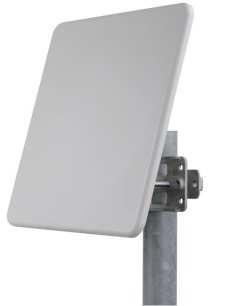
10 3 Mounting Details 3.1 iant200 Place the antenna bracket into desired location as stipulated in the report and mark the B holes. Remove the bracket and drill two holes using a 6mm drill approximately 30mm deep. Plug the holes using the red rawl plugs. Re-align the bracket and fix using suitable screws. Place the antenna onto the bracket and fix through A using M6 lock washer & M6 x10 slotted machine screw. Attach connector to RF equipment and tidily secure excess cable. 10
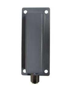
11 3.2 iant212 The iant212 is designed to be mounted directly to wireless devices; therefore no mounting bracket is supplied with this antenna. 3.3 iant213 The IANT213 is supplied with a pole mount bracket and clamps. 11
12 Operating Manual 3.4 iant214 12

13 3.5 iant iant216 The iant216m is designed to be mounted directly to wireless devices. The iant216f is supplied with a pole mount bracket as standard. 13


14 Operating Manual 3.7 iant217 Mounting bracket is available. The iant217 is suitable for wall or pole mounting. Pole mount bracket Extronics part number: iantmb217. Note: this bracket is aluminium and is not suitable Group I and Zone 0 areas. 14
, flat washers (10) and nuts (12). 3. Tighten the nuts at a torque of 30 Lbs*In. 4.")
 Leave screw slightly loose. 5. Connect item No. 3 to item No. 5 as illustrated, with items 6, 7,8,13.")
, and connect those using items No. 6, 7, and 9.")

15 3.8 iant218 / iant219 / iant220 / iant Place item No.2 on the antenna, as illustrated in the drawing. Align with the screw holes. 2. Connect item No. 2 to the antenna with spring washers (11), flat washers (10) and nuts (12). 3. Tighten the nuts at a torque of 30 Lbs*In. 4. Connect item No. 3 to item No. 2 ONLY as illustrated in Fig.2, with items 6, 7,8,13. (Teeth of item 2 facing teeth of item 3) Leave screw slightly loose. 5. Connect item No. 3 to item No. 5 as illustrated, with items 6, 7,8,13. (Teeth of item 5 facing teeth of item 3) Leave screw slightly loose. 6. For pole mounting attach items No. 4 and 5 to the pole as illustrated (Fig 4), and connect those using items No. 6, 7, and 9. Close screws (9) one and another in turn up to tightening torque of each screw is Lbs In. Distance between ends of items 4, 5 on one and another side must be equal. NO SKEWNESS ALLOWED. 7. For wall mounting attach item 5 to the wall (Fig 5). Fasten it with screws 1/4 or M6 using holes A. (Screws not supplied). 8. Adjust the desired angle, and fully tighten the loose screws (paragraphs 4, 5) at a torque of 30 Lbs In. 15
16 3.8 iant222 The antenna can be mounted and positioned with the galvanised steel bracket supplied for mast or pole mounting. 16
17 4 Manual Revision Issued By: Andy Peak Issue Date : 25/02/2014 Approved By: Nick Saunders Approval Date : 23/01/2017 Doc Ref: Revision: 3.1 Document Change History ATEX RELATED DOCUMENT THIS DOCUMENT MUST NOT BE MODIFIED WITHOUT PRIOR PERMISSION FROM THE AUTHORISED PERSON Red Issue Change Details Of Change Date Line No. d By PIL ECN Approved by: 1.0 AJP Modified range new antennas added. D of C removed, Doc 25/02/2014 N/A N/A NS number changed from BTS Update range 03/09/2014 N/A N/A NS 2.1 JR Added to Extronics Winman BMS 29/07/2015 N/A N/A NS 2.2 PR Antenna mounting bracket drawings added. 08/10/2015 N/A N/A NS New drawing for iant PR New images on front page. 25/10/2016 N/A N/A NS New table showing maximum RF power. IANT216 and iant217 mounting brackets added. Antenna data removed from this manual, refer to individual datasheets for latest data 3.1 PR New signed revision sheets added 23/01/2017 N/A N/A NS Notes: N/A This document is not to be modified without prior reference to an authorized person. Authorised Signature 17
Operating Manual. isolate501
 Operating Manual isolate501 Document Number 413569 (See Last Page for Revision Details). Copyright Extronics Ltd, 2015 Page 2 of 21 Contents 1 Introduction... 4 2 Safety Information and Notes... 5 2.1
Installation & Operating Manual. iwap202
 Installation & Operating Manual iwap202 This page is intentionally left blank. Document Number 409345 (based on 407655) (See Last Page for Revision Details) For warranty information, refer to Terms and
Safety Manual. Omni-ID UHF Tags
 Safety Manual Omni-ID UHF Tags This page is intentionally left blank. Document Number 330556 (See Last Page for Revision Details) 2012 Extronics Limited. This document is Copyright Extronics limited. Extronics
FM Safety Manual. Omni-ID UHF Tags
 FM Safety Manual Omni-ID UHF Tags This page is intentionally left blank. Document Number 334169 (See Last Page for Revision Details) 2012 Extronics Limited. This document is Copyright Extronics limited.
iant101 Zone 1 Omni Directional Antenna
 iant101 Zone 1 Omni Directional Antenna External Antenna offering increased flexibility for positioning and greatly enhanced RF Propagation. ATEX Ex t IIIC T85 C Db IECEx Ex t IIIC T85 C Db -40 C to 60
Cisco Outdoor Omnidirectional Antenna for 2G/3G/4G Cellular (ANT-4G-OMNI-OUT-N)
") CHAPTER 4 Cisco Outdoor Omnidirectional Antenna for 2G/3G/4G Cellular (ANT-4G-OMNI-OUT-N) The Cisco Outdoor Omnidirectional Antenna for 2G/3G/4G Cellular antenna is designed to cover domestic LTE700/Cellular/PCS/AWS/MDS,
CHAPTER 4 Cisco Outdoor Omnidirectional Antenna for 2G/3G/4G Cellular (ANT-4G-OMNI-OUT-N) The Cisco Outdoor Omnidirectional Antenna for 2G/3G/4G Cellular antenna is designed to cover domestic LTE700/Cellular/PCS/AWS/MDS,
MTS-SP100. RENOGY Pole Mount System E Philadelphia St, Ontario, CA Version: 1.2
 MTS-SP100 RENOGY Pole Mount System 2775 E Philadelphia St, Ontario, CA 91761 1-800-330-8678 1 Version: 1.2 Important Safety Instructions Please save these instructions. This manual contains important safety,
INSTRUCTION MANUAL (ATEX / IECEx)
") INSTRUCTION MANUAL (ATEX / IECEx) STExS1 & STExS2 Sounder For use in Flammable Gas and Dust Atmospheres 1) Warnings DO NOT OPEN WHEN AN EXPLOSIVE ATMOSPHERE IS PRESENT POTENTIAL ELECTROSTATIC CHARGING
INSTRUCTION MANUAL (ATEX / IECEx) STExS1 & STExS2 Sounder For use in Flammable Gas and Dust Atmospheres 1) Warnings DO NOT OPEN WHEN AN EXPLOSIVE ATMOSPHERE IS PRESENT POTENTIAL ELECTROSTATIC CHARGING
OMEGA. Communications Interface Cabinet. Antenna Installation Manual
 Ω OMEGA Communications Interface Cabinet Antenna Installation Manual 0049-0706-004 The products and programs described in this User s Guide are licensed products of Telenetics Corporation. This User s
SIMATIC Ident. RFID systems SIMATIC RF615A. Characteristics 1. Ordering data. Installing and mounting. Connecting the antenna 4
 Characteristics 1 Ordering data 2 SIMATIC Ident RFID systems Operating Instructions Installing and mounting 3 Connecting the antenna 4 Antenna parameter assignment 5 Antenna patterns 6 Maximum read/write
Hazardous environments
 World class antenna solutions for Hazardous environments EX certified antennas for professional communication Amphenol PRIVATE NETWORKS 1 Procom Ex certified antennas Safety in places where mistakes cannot
PLANISHING HAMMER STAND OWNER S MANUAL
 PLANISHING HAMMER STAND OWNER S MANUAL WARNING: Read carefully and understand all INSTRUCTIONS before operating. Failure to follow the safety rules and other basic safety precautions may result in serious
ORiNOCO AP-4000MR-LR and AP-4900MR-LR Access Points Safety and Regulatory Compliance Information
 IMPORTANT! Visit http://support.proxim.com for the latest safety and regulatory compliance information for this product. ORiNOCO AP-4000MR-LR and AP-4900MR-LR Access Points Safety and Regulatory Compliance
Installation Job Aid (English) for Avaya WLAN 8100 series- WLAN AP 8120 with External Antenna
 for Avaya WLAN 8100 series- WLAN AP 8120 with External Antenna") Release 3.0 NN47251-311 Issue 02.01 June 2014 Installation Job Aid (English) for Avaya WLAN 8100 series- WLAN AP 8120 with External Antenna How to get help To access the complete range of services and
Release 3.0 NN47251-311 Issue 02.01 June 2014 Installation Job Aid (English) for Avaya WLAN 8100 series- WLAN AP 8120 with External Antenna How to get help To access the complete range of services and
Solexy USA, LLC International Blvd Cincinnati, Ohio Phone: Fax:
 OVERVIEW The Solexy RX series explosion proof and intrinsically safe antenna coupler is an integrated protection device that facilitates non-ex certified radio antenna installation in hazardous areas.
Planishing hammer stand For use with SKU Planishing hammer
 Planishing hammer stand For use with SKU 94847 Planishing hammer Model 96300 Assembly And Operation Instructions Please Note: Planishing Hammer not included with Stand. Due to continuing improvements,
Cisco Aironet 2.4-GHz/5-GHz 8-dBi Directional Antenna (AIR-ANT2588P3M-N)
") Cisco Aironet.4-GHz/5-GHz 8-dBi Directional Antenna (AIR-ANT588P3M-N) This document outlines the specifications for the Cisco Aironet AIR-ANT588P3M-N.4/5-GHz 8-dBi 3-Port Directional Antenna with N-connectors
Cisco Aironet.4-GHz/5-GHz 8-dBi Directional Antenna (AIR-ANT588P3M-N) This document outlines the specifications for the Cisco Aironet AIR-ANT588P3M-N.4/5-GHz 8-dBi 3-Port Directional Antenna with N-connectors
HP ProCurve 6.9/7.7dBi Dual Band Directional Antenna (J8999A) Guide
 Guide") HP ProCurve 6.9/7.7dBi Dual Band Directional Antenna (J8999A) Guide SAFETY The HP ProCurve J8999A and all associated equipment should be installed in accordance with applicable local and national electrical
HP ProCurve 6.9/7.7dBi Dual Band Directional Antenna (J8999A) Guide SAFETY The HP ProCurve J8999A and all associated equipment should be installed in accordance with applicable local and national electrical
Antenna Splitter ASA 1. Instruction manual
 Antenna Splitter ASA 1 Instruction manual Contents Contents Important safety instructions... 2 The ASA 1 active antenna splitter... 4 Combination possibilities of ASA 1/ASA 1-1G8... 5 Delivery includes...
Making Safe Waves in Hazardous Areas
 Making Safe Waves in Hazardous Areas A Wireless White Paper Wireless Vision Engineering Tracking Author: John Hartley Managing Director - Extronics Limited October 2014 Making Safe Waves in Hazardous Areas
Analog Universal Module HART for Zone 2 Series 9468/33
 > 8 channels can be adjusted individually as analog inputs or outputs > Intrinsically safe inputs/outputs Ex ia > For 0/4 20 ma + HART signals > Line fault monitoring per channel > Diagnostics based on
BAR-ANT-N-N-EX. Antenna barrier for the hazardous area. Data sheet. 1 Description
 BAR--N-N-EX Antenna barrier for the hazardous area Data sheet 060_en_00 PHOENIX CONTACT 05-06-0 Description Using an antenna barrier, you can execute HF outputs of wireless modules with intrinsic safety.
Standard Pole Mount Parabolic Antenna Mounting Instructions 3 ft. (90cm) & 4 ft. (120cm)
 & 4 ft. (120cm)") 495 R Billerica Ave. N. Billerica, MA 01862 USA Tel: (978) 459-8800 Fax: (978) 459-3310 / 8814 www.radiowavesinc.com email: sales@radiowavesinc.com Standard Pole Mount Parabolic Antenna Mounting Instructions
495 R Billerica Ave. N. Billerica, MA 01862 USA Tel: (978) 459-8800 Fax: (978) 459-3310 / 8814 www.radiowavesinc.com email: sales@radiowavesinc.com Standard Pole Mount Parabolic Antenna Mounting Instructions
Safety in Hazardous Environments
 Safety in Hazardous Environments World Class antenna solutions for Critical Industrial Applications EX certified antennas for professional communication 1 Improve quality of service Procom Ex certified
Pressure transmitters MBS 4201, MBS 4251, MBS 4701 and MBS 4751
 060R9345 Instructions Pressure transmitters MBS 4201, MBS 4251, MBS 4701 and MBS 4751 Content Page 1 Description/application 2 Identification 3 Specifications 4 Safety instructions 5 Installation/dimensions
ANT400 OPTIONAL REMOTE ANTENNA MODULE
 P516-099 ANT400 OPTIONAL REMOTE ANTENNA MODULE INSTRUCTIONS FOR ANT400-REM-I/O, ANT400-REM-I/O+6dB, ANT400-REM-CEILING, ANT400-REM-HALL Para el idioma español, navegue hacia www.schlage.com/support. Pour
Cisco Aironet 13.5-dBi Yagi Mast Mount Antenna (AIR-ANT1949)
") Cisco Aironet 13.5-dBi Yagi Mast Mount Antenna (AIR-ANT1949) Overview This document describes the 13.5-dBi Yagi mast mount antenna and provides instructions for mounting it. The antenna operates in the
Cisco Aironet 13.5-dBi Yagi Mast Mount Antenna (AIR-ANT1949) Overview This document describes the 13.5-dBi Yagi mast mount antenna and provides instructions for mounting it. The antenna operates in the
S5-ADU. Front... 4 Rear... 4
 Trantec ANTENNA DISTRIBUTOR INSTRUCTION MANUAL S5-ADU Thank you for purchasing TRANTEC Antenna Distributor. Please carefully follow the instructions in this manual to ensure long, trouble-free use of your
For use in Flammable Gas and Dust Atmospheres
 ISTRUCTIO MAUA (ATEX) BExCBG0505D Flameproof Combined / For use in Flammable Gas and Dust Atmospheres 1) Introduction The BExCBG0505D is a second generation flameproof combined beacon / beacon which is
GETTING STARTED GUIDE NI AI, ±60 V, 24 Bit, 1 ks/s/ch Simultaneous
 GETTING STARTED GUIDE NI 9228 8 AI, ±60 V, 24 Bit, 1 ks/s/ch Simultaneous This document explains how to connect to the NI 9228. Note Before you begin, complete the software and hardware installation procedures
INS-AS Dual Bracket Mounting Kits for Quintel Antennas
 The Quintel Optimal Separation (QOS) Dual Mount Antenna Bracket Kit allows a variable horizontal separation for a single band or across multiple bands for two Quintel QS Series antennas when operating
MT MOTORI ELETTRICI. Installation, operation, maintenance and safety manual for motors used in hazardous areas 1-II-2G 21-II-2D
 MT MOTORI ELETTRICI Installation, operation, maintenance and safety manual for motors used in hazardous areas 1-II-2G 21-II-2D TABLE OF CONTENTS 1. Introduction 2. Scope of application 3. Installation
Owner s Manual & Safety Instructions
 Owner s Manual & Safety Instructions Save This Manual Keep this manual for the safety warnings and precautions, assembly, operating, inspection, maintenance and cleaning procedures. Write the product s
GETTING STARTED GUIDE NI AI, ±10 V, 24 Bit, 50 ks/s/ch Simultaneous
 GETTING STARTED GUIDE NI 9239 4 AI, ±10 V, 24 Bit, 50 ks/s/ch Simultaneous This document explains how to connect to the NI 9239. Note Before you begin, complete the software and hardware installation procedures
Single Band 125mm Profile Panel Antennas Installation and Operation Instructions Including APM-F-084-S4 & APM-T-085-S4 Mounting Kits
 General Single Band 125mm Profile Panel Antennas Installation and Operation Instructions Including APM-F-084-S4 & APM-T-085-S4 Mounting Kits This instruction sheet contains all necessary information required
Temperature Input Module for Zone 1 Series 9482/32
 www.stahl.de > 8 channels for temperature sensors > Intrinsically safe inputs Ex ia > For Pt-, Ni- and Cu-resistance temperature detectors according to DIN, IEC and GOST in 2-, 3- and 4-wire circuits >
MSP-DCCPGSU Large Screen Static Display Mount
 INSTALLATION INSTRUCTIONS Large Screen Static Display Mount The Large Screen Static Display Mount () is a quick disconnect mounting solution for large flat panel displays. The mount self-adjusts for the
Type XTSR71 Sizes
 (Page 1 of 13) s 494-5258 Type XTSR71 s 494-5258 Figure 1 Thomas XTSR71 Coupling 1. General Information 1.1 Thomas Couplings are designed to provide a mechanical connection between the rotating shafts
MSP-DCCPGTU Large Screen Tilt Display Mount
 INSTALLATION INSTRUCTIONS Large Screen Tilt Display Mount The Large Screen Tilt Display Mount is a quick disconnect mounting solution for large flat panel displays. The mount features infinite adjust ability
2 Pipe Clamp Bracket 3 11 M6 Screw with Tube M6 Hex Nut 2 4 M20 Flat Washer 4
 3842 Revision B, May 201 Mounting Kit, For Metro Cell Antennas MC-MNT-TOP-2 Mounting Kit GENERAL INFORMATION Top of pole mounting option Fits round members.3" to 8." (10 to 21 mm) pole diameter. PRE-INSTALLATION
Pole Mount Installation Guide
 Pole Mount Installation Guide (No Fine Adjustment) 495R Billerica Ave. North Billerica, MA 01862 USA Tel (978)459-8800 fax (978)459-3310 / 8814 Email: sales@radiowaves.com www.radiowaves.com IMPORTANT!
Owner s Manual & Safety Instructions
 Owner s Manual & Safety Instructions Save This Manual Keep this manual for the safety warnings and precautions, assembly, operating, inspection, maintenance and cleaning procedures. Write the product s
MODEL 83 Pail Handler
 MORSE MFG. CO., INC. 727 West Manlius Street P.O. Box 518 East Syracuse, NY 13057-0518 Phone: 315-437-8475 Fax: 315-437-1029 Email: service@morsemfgco.com Website: www.morsemfgco.com COPYRIGHT 2005 MORSE
Digital Input Output Module 24 V for Ex n Zone 2 Series 9472/35
 www.stahl.de > 16 channels can be adjusted in pairs as digital inputs or outputs > Suitable for NAMUR proximity switches, 3-wire PNP proximity switches, contacts and solenoid valves (24 V / 0.5 A). > Up
Model 3180B Mini-Bicon Antenna User Manual
 Model 3180B Mini-Bicon Antenna User Manual Model 3180B with conical elements Model 3180B with cage elements ETS-Lindgren L.P. reserves the right to make changes to any product described herein in order
WALK-BEHIND SPREADER 50 LB. CAPACITY Model 99623
 WALK-BEHIND SPREADER 50 LB. CAPACITY Model 99623 Assembly, Operating, and Maintenance Instructions Diagrams within this manual may not be drawn proportionally. Due to continuing improvements, actual product
Double-Ridged Waveguide Horn Antennas
 Models 3112, 3106B, 3119, 3115, 3117, 3116C Double-Ridged Waveguide Horn Antennas User Manual ETS-Lindgren Inc. Although the information in this document has been carefully reviewed and is believed to
TC ANT MOBILE... Mobile communication antennas and antenna cables. Data sheet _en_00. 1 Description
 Mobile communication antennas and antenna cables Data sheet 106760_en_00 PHOENIX CONTACT 2015-08-11 1 Description This data sheet describes the accessories for mobile communication products. All mobile
Industrial Pressure Transducers
 Industrial Pressure Transducers User s Manual T Model T Model The Swagelok T model transducer is engineered for use in industrial pressure measurement applications where intrinsically safe ratings are
Mounting Instructions for Cisco Aironet 1550 Series Outdoor Access Point Pole-Mount Kits
 Mounting Instructions for Cisco Aironet 1550 Series Outdoor Access Point Pole-Mount Kits Date: April 2011 Part number: This document describes how to use the Cisco Aironet 1550 Series Outdoor Access Point
ProCurve 7 dbi Dual Band Directional antenna
 GROUNDING System grounding and lightning protection are essential, especially for exterior-mounted antennas exposed to the elements. Never install an antenna where it may fall and contact electrical lines
Cisco Aironet Six-Element Dual-Band MIMO Patch Array Antenna (AIR-ANT25137NP-R)
") Cisco Aironet Six-Element Dual-Band MIMO Patch Array Antenna (AIR-ANT25137NP-R) August 2, 2013 This document describes the AIR-ANT25137NP-R antenna and provides instructions for mounting it. The antenna
Cisco Aironet Six-Element Dual-Band MIMO Patch Array Antenna (AIR-ANT25137NP-R) August 2, 2013 This document describes the AIR-ANT25137NP-R antenna and provides instructions for mounting it. The antenna
Installing flat panels on the MPL15 wall mount
 Installing flat panels on the MPL15 wall mount The MPL15 (DS-VW775) is a full-service video wall mount that can accommodate tiled LCD panels with up to a 400 x 400 mm VESA pattern in portrait and landscape
Installation Instructions TMW Antenna Tower Mount for 4ft (1.2m) Antennas.
 Antennas.") Description The following pages show the steps required to assembly and fit the antenna mount to a vertical tower pipe of diameter 48 to 115 mm (1.9 to 4.5"). This mount provides ±20 azimuth or ±15 elevation
Description The following pages show the steps required to assembly and fit the antenna mount to a vertical tower pipe of diameter 48 to 115 mm (1.9 to 4.5"). This mount provides ±20 azimuth or ±15 elevation
TZ-RD-1740 Rotary Dipole Instruction Manual
 TZ-RD-1740 17/40m Rotary Dipole Instruction Manual The TZ-RD-1740 is a loaded dipole antenna for the 40m band and a full size rotary dipole for the 17m band. The antenna uses an aluminium radiating section
Digital Input Output Module for Zone 2 Series 9470/33
 www.stahl.de > 16 channels can be adjusted in pairs as digital input or output > Intrinsically safe inputs/outputs Ex ia > For contacts, NAMUR proximity switches and low-power solenoid valves > Up to 8
SOLAR PANEL ACCESSORY. Solar Panel Mounting Bracket installation manual. Solar Panel Mounting Bracket
 SOLAR PANEL ACCESSORY Solar Panel Mounting Bracket installation manual Solar Panel Mounting Bracket Company Profile 1986 1990 1995 1999 Centurion Systems today In-house R & D development team Manufacture
DUST COLLECTOR 70 GALLON, 2 HP
 DUST COLLECTOR 70 GALLON, 2 HP Model 45378 ASSEMBLY AND OPERATING INSTRUCTIONS 3491 Mission Oaks Blvd., Camarillo, CA 93011 Visit our Web site at http://www.harborfreight.com Copyright 2001 by Harbor Freight
Nemalux INSTALLATION INSTRUCTIONS APPLICATION 1-4
 I N D U S T R I A L rev. A- INSTALLATION INSTRUCTIONS *PENDING* E77827 E77827 APPLICATION MR3 & MR6 Luminaires are suitable for use in the following areas as defined by the National Electrical Code (NEC)
MINI MCR-SL-UI-I-LP-NC
 2-way isolation amplifier Data sheet 105263_en_02 PHOENIX CONTACT 2013-12-13 1 Description The configurable 2-way isolation amplifiers are used to electrically isolate, convert and filter standard signals.
User Guide. Keysight N6850A Broadband Omnidirectional Antenna
 User Guide Keysight N6850A Broadband Omnidirectional Antenna Notices Keysight Technologies, Inc. 2012-2015 No part of this manual may be reproduced in any form or by any means (including electronic storage
2-Slot Desktop Chassis (DC) Extended Temperature
 Extended Temperature") APRIL 2008 LMC5202A 2-Slot Desktop Chassis (DC) Extended Temperature Copyright 2008. Black Box Corporation. All rights reserved 50 80105BB 01 A0 1000 Park Drive Lawrence, PA 35055 1018 724 746 5500 Fax
APRIL 2008 LMC5202A 2-Slot Desktop Chassis (DC) Extended Temperature Copyright 2008. Black Box Corporation. All rights reserved 50 80105BB 01 A0 1000 Park Drive Lawrence, PA 35055 1018 724 746 5500 Fax
4-Port Antenna Frequency Range Dual Polarization HPBW Adjust. Electr. DT
 4-Port Antenna Frequency Range Dual Polarization HPB Adjust. Electr. DT R1 790 960 0 10 2 8 set by hand or by optional RCU (Remote Control Unit) X 65 Y1 1710 2690 X 65 4-Port Antenna 790 960/1710 2690
6-Port Antenna Frequency Range Dual Polarization HPBW Adjust. Electr. DT set by hand or by optional RCU (Remote Control Unit)
") 6-Port Antenna Frequency Range Dual Polarization HPBW Adjust. Electr. DT R1 698 960 1710 2690 1710 2690 1.5 10 0 10 2 10 set by hand or by optional RCU (Remote Control Unit) X Y1 X Y2 65 65 65 X 6-Port
6-Port Antenna Frequency Range Dual Polarization HPBW Adjust. Electr. DT R1 698 960 1710 2690 1710 2690 1.5 10 0 10 2 10 set by hand or by optional RCU (Remote Control Unit) X Y1 X Y2 65 65 65 X 6-Port
15 Planer Stand. Model Due to continuing improvements, actual product may differ slightly from the product described herein.
 15 Planer Stand Model 96316 Assembly And Operation Instructions Due to continuing improvements, actual product may differ slightly from the product described herein. 3491 Mission Oaks Blvd., Camarillo,
INSTALLATION INSTRUCTIONS UTV LIGHT BAR KIT Part Number: and Application: All UTV s*
 INSTALLATION INSTRUCTIONS UTV LIGHT BAR KIT Part Number: 83970 and 84360 Application: All UTV s* * does not include Arctic Cat vehicles Your safety, and the safety of others, is very important. To help
4-Port Antenna Frequency Range Dual Polarization HPBW Adjust. Electr. DT
 4-Port Antenna Frequency Range Dual Polarization HPB Adjust. Electr. DT R1 790 960 0.5 9.5 0 6 set by hand or by optional RCU (Remote Control Unit) X 65 B1 1710 2180 X 65 4-Port Antenna 790 960/1710 2180
AC 3. Active Antenna Combiner. Instruction manual
 AC 3 Active Antenna Combiner Instruction manual Contents Contents Important safety instructions... 2 The AC 3 active transmitter combiner... 4 Delivery includes... 4 Operating controls... 5 Block diagram...
Trouble Free Hardware
 Backs and Support OWNER MANUAL Trouble Free Hardware TFB Hardware Trouble Free Owner s Manual Customer Satisfaction 1.0 Stealth Products strives for 100% customer satisfaction. Your complete satisfaction
GETTING STARTED GUIDE NI khz to 100 MHz, 50 Ω, AC Coupled RF Receiver Module
 GETTING STARTED GUIDE NI 9770 30 khz to 100 MHz, 50 Ω, AC Coupled RF Receiver Module This document explains how to connect to the NI 9770. Note Before you begin, complete the software and hardware installation
Intrinsically Safe Compact Controller CTR 210i. Intrinsically Safe Bargraph Indicator. BGI 210i
 Intrinsically Safe Compact Controller CTR 210i Intrinsically Safe Bargraph Indicator BGI 210i DMT 02 ATEX E 148 2. Supplement also grahics display Revision 4 IBS BatchControl GmbH Im Sträßchen 2 4 Tel.:
ROLLER STAND WITH TWO-LEG SUPPORT ASSEMBLY AND OPERATING INSTRUCTIONS
 ROLLER STAND WITH TWO-LEG SUPPORT 95621 ASSEMBLY AND OPERATING INSTRUCTIONS 3491 Mission Oaks Blvd., Camarillo, CA 93011 Visit our Web site at http://www.harborfreight.com Copyright 2006 by Harbor Freight
OPTIWAVE 7300 C Supplementary instructions
 OPTIWAVE 7300 C Supplementary instructions Radar (FMCW) Level Transmitter for agitated liquids in process applications Supplementary Instructions for ATEX applications KROHNE CONTENTS OPTIWAVE 7300 C General
CABANA / PAVILION ASSEMBLY ALUMINUM FRAME MODELS
 Assembled cabanas are large & heavy. Assemble at place of use. CABANA / PAVILION ASSEMBLY ALUMINUM FRAME MODELS Step 1 CAUTION: To avoid damage to the finish of your Cabana frame, prepare a smooth, non-scratch
Installation Instructions
 Installation Instructions For 0.2m Ultra-high Performance Antenna Model ADxxG-0-T2 Before Installation, please read these instructions carefully. This instruction guide is for the installation of 8 inch
K1FO 12 ELEMENT 144/147 MHz YAGI
 K1FO 12 ELEMENT 144/147 MHz YAGI WARNING: INSTALLATION OF THIS PRODUCT NEAR POWER LINES IS DANGEROUS. FOR YOUR SAFETY FOLLOW THE INSTALLATION DIRECTIONS. Ariane Arrays, Inc. Copyright 2006 201 Hopedale
18 PIECE HOLE SAW SET
 18 PIECE HOLE SAW SET 94665 ASSEMBLY AND OPERATING INSTRUCTIONS Due to continuing improvements, actual product may differ slightly from the product described herein. 3491 Mission Oaks Blvd., Camarillo,
Circularly Polarized FM Broadcast Antenna
 Circularly Polarized FM Broadcast Antenna Versa2une (SLV) 6 to 12-bay, full-wave-spaced Instruction Manual Installation, Operation, & Maintenance Congratulations! Thank you for purchasing one of the finest
Continuous Handrail Kit Installation Instructions
 Continuous Handrail Kit Installation Instructions ALUMINUM RAILING SYSTEM Canadian Version Wall Application (see page 2) Railing Application (see page 7) Wall anchors not provided Hardware included: 1x
Wireless Dual Discrete Input Transmitter Series XYR 5000, Model WW59x Specifications - Americas
 Wireless Dual Discrete Input Transmitter Series XYR 5000, Model WW59x Specifications - Americas 34-XY-03-12 February 2008 Function The WW59x Dual Discrete Input Field Transmitter is part of the XYR 5000
Transducer transmitter BILT 4 II 2(1) G. Technical Manual
 G. Technical Manual") GB Transducer transmitter BILT 4 II 2(1) G Technical Manual Transducer transmitter BILT 4 Contents Introduction General... 3 Ex.safety description... 4 Technical data... 5 Installation General... 6 Mechanical
GB Transducer transmitter BILT 4 II 2(1) G Technical Manual Transducer transmitter BILT 4 Contents Introduction General... 3 Ex.safety description... 4 Technical data... 5 Installation General... 6 Mechanical
1. TABLE OF CONTENT 2. ASSEMBLY ATEX. PENCOflex Installation Instructions & Service Manual
 ATEX 1. TABLE OF CONTENT 1. Table Of content... 1 2. Assembly... 1 3. Alignment... 2 4. Earthing... 3 5. Inspection and replacement of Elastic elements... 4 5.1. Rubber elements... 4 5.2. Pins... 4 5.2.1
Analog Input Module HART Ex i / I.S. Inputs, Channels Type 9461/
 > 4 channels for 2-wire HART transmitters and 4 channels for 4-wire HART transmitters > Intrinsically safe inputs Ex ia IIC > Galvanic separation between inputs and system > Open-circuit and short-circuit
clamps included Single Unit Double Unit
 Designed for co-siting purposes Enables feeder sharing Can be used as a combiner near the BTS or in a reciprocal function near the antenna Suitable for indoor or outdoor applications Wall or mast mounting
Intrinsically safe pressure transmitter MBS 4201, MBS 4251, MBS 4701 and MBS 4751
 Data sheet Intrinsically safe pressure transmitter MBS 420, MBS 425, MBS 470 and MBS 475 The intrinsically safe pressure transmitter program is designed for use in hazardous environments and offers a reliable
FLEX Ex V ac In/Quad-Ex dc Out Power Supply
 Installation Instructions FLEX Ex 85 250V ac In/Quad-Ex dc Out Power Supply Catalog Number 1797-PS1N Topic Important User Information 2 About the Power Supplies 3 Understand System Planning 4 Electrostatic
OWNER S MANUAL STORAGE SHED MODELS: STOR-96-G-W-1RH & STOR-912-G-W-1RH
 STORAGE SHED MODELS: STOR-96-G-W-1RH & STOR-912-G-W-1RH OWNER S MANUAL Introduction.. 1 Assembly Instructions STOR-96-G-W-1RH... 2 Assembly Instructions STOR-912-G-W-1RH... 8 STOR-96-G-W-1RH Exploded Parts
I SERIES IVY1122 IVY1152 IVY1153. BalancePoint Flyware For Point Source and Subwoofer loudspeakers models IP8, IP6, IS8, and IS6
 I SERIES BalancePoint Flyware For Point Source and Subwoofer loudspeakers models IP8, IP6, IS8, and IS6 IVY1122 IVY1152 IVY1153 Vertical Yokes for IP6/8-1122, IP6/8-1152, IP8-1153 The BalancePoint Flyware
Accessories Solar Datatechnology Wireless-Set485-01/-Set485-02
 Accessories Solar Datatechnology Wireless-Set485-01/-Set485-02 Installation Guide WirelessSet485-IEN091511 98-0009411 Version 1.1 EN SMA Solar Technology AG Table of Contents Table of Contents 1 Notes
Model BiConiLog Antenna. User Manual
 Model 3149 BiConiLog Antenna User Manual ETS-Lindgren Inc. reserves the right to make changes to any products herein to improve functioning or design. Although the information in this document has been
HAZARDOUS AREA SOLUTIONS
 HAZARDOUS AREA SOLUTIONS WIRELESS & Systems ATEX IP66 Zones 1 and 2 v. 1.1/16 2 Delvalle, wide experience in manufacturing solutions for hazardous area We put at your disposal We offer over 40 years providing
4-Port Antenna Frequency Range Dual Polarization HPBW Adjust. Electr. DT set by
 4-Port Antenna Frequency Range Dual Polarization HPB Adjust. Electr. DT set by R1 698 960 X 65 2 12 R2 698 960 X 65 2 12 4-Port Antenna 698 960/698 960 65 /65 15.5/15.5dBi 2 12 /2 12 T Type No. 80010901
ER WIRELESS TRANSMITTER
 ER WIRELESS TRANSMITTER ER-310 / ER-320 Cosasco s Electrical Resistance (ER) Wireless Transmitters are based on Cosasco s ER corrosion measurement technology, the industry s most widely used and only technology
4-Port Antenna ircu / /65 16/18.5dBi 0 10 /0 10 T V01
 4-Port Antenna Frequency Range Dual Polarization Half-power Beam Width Integrated replaceable Remote Control Unit Adjustable Electrical Downtilt 0 10 0 10 4-Port Antenna 698 894/1710 2170 65 /65 16/18.5dBi
OPTITEMP TT 10 C/R Technical Datasheet
 OPTITEMP TT 10 C/R Technical Datasheet Analogue 2-wire temperature transmitter Temperature linear 4...20 ma output Rangeable with solder pads and potentiometers Easy wiring through large center hole The
Installation Guide Flat Panel Antenna Mounting Kit For
 Installation Guide Flat Panel Antenna Mounting Kit For 103670-1 495R Billerica Ave. North Billerica, MA 01862 USA Tel (978)459-8800 fax (978)459-3310 / 8814 Email: sales@radiowaves.com www.radiowaves.com
Dual Arm Tilt LCD Mount
 Installation Manual model # 51324 M o u n t i n g S y s t e m s Dual Arm Tilt LCD Mount Fits Displays 13 to 32 Supports Up to 50 lbs (23 kgs) Projection from Wall from 3 to 17 Meets VESA Standards 50/75/100,
Digital Input Output Module for Zone 2 Series 9470/33
 www.stahl.de > 16 can be adjusted in pairs as digital input or output > Intrinsically safe inputs/outputs Ex ia > For contacts, NAMUR proximity switches and low-power solenoid valves > Up to 8 can be used
FORD MOUNT INSTALLATION INSTRUCTIONS
 WESTERN PRODUCTS, P.O. BOX 245038, MILWAUKEE, WI 53224-9538 Lit. No. 64289 June 1, 2003 FORD MOUNT INSTALLATION INSTRUCTIONS Bronco (4X4 only) F-150 (4X4 only), F-250/350 Super Duty 1980 1991 Model No.
ATV CULTIVATOR OWNER S MANUAL
 ATV CULTIVATOR OWNER S MANUAL WARNING: Read carefully and understand all ASSEMBLY AND OPERATION INSTRUCTIONS before operating. Failure to follow the safety rules and other basic safety precautions may