Ionospheric Propagation
|
|
|
- Dorthy Wilcox
- 6 years ago
- Views:
Transcription
1 Ionospheric Nick Massey VA7NRM 1

2 Electromagnetic Spectrum Radio Waves are a form of Electromagnetic Radiation Visible Light is also a form of Electromagnetic Radiation Radio Waves behave a lot like light but, the wavelength of radio waves is 1000 m to 0.01 m whereas the wavelength of light about 500 x 10-9 m HF Radio has wavelengths from 200 m to 10 m 2
3 Path Loss Good Path Transmit 100 Watts (+50 dbm) Receive an S9 signal, Watts (-73 dbm) Path loss is 1: 2,000,000,000,000 (123 db) 20 Trucks carry 2,000,000,000,000 grains of sugar Poor Path Transmit 1000 Watts (+60 dbm) Receive an S4 signal, Watts (-103 dbm) Path loss is 1: 20,000,000,000,000,000 (163 db) 40 Ships carry 20,000,000,000,000,000 grains of sugar 3
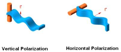
4 Polarisation (Linear) 4
5 Circular Polarisation E Field Vector Rotates Right-hand (CW) or Left-hand (CCW) Elliptical Polarisation - amplitudes are not equal Linear polarised wave can be created from two counter-rotating Circular polarised waves 5

6 Space Weather Parts I and II Ionosphere UV Radiation Magnetosphere Solar Wind Cycles Sun Spot (~11 Yrs) Seasonal Diurnal Storms Geomagnetic Storms - Solar Wind Blackouts - X-rays Solar Radiation Storms - Protons 6
7 Ionisation Atmospheric gas particles become positively charged ions by removal of negatively charged electrons Plasma In sufficient quantity, free electrons affect the velocity of radio wave propagation Energy to produce ionisation comes from ultraviolet and x-ray radiation from the sun In the absence of ionising energy, the ionised particles die away due to collisions between ions and electrons 7
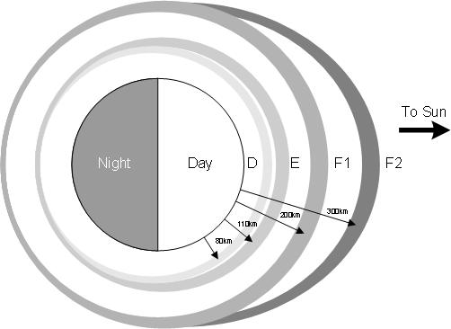
8 Ionised Layers D Layer km, Only during daytime Attenuates radio waves passing through it (Collision Freq.) AM broadcast stations stronger at night E Layer km, Always present Primarily useful for daytime km links Sporadic E F Layer Day F km and F km, Night F2 300 km F2 is most used layer for HF communications 8
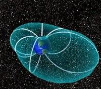
9 The Ionosphere 9

10 The Ionosphere To scale! 10
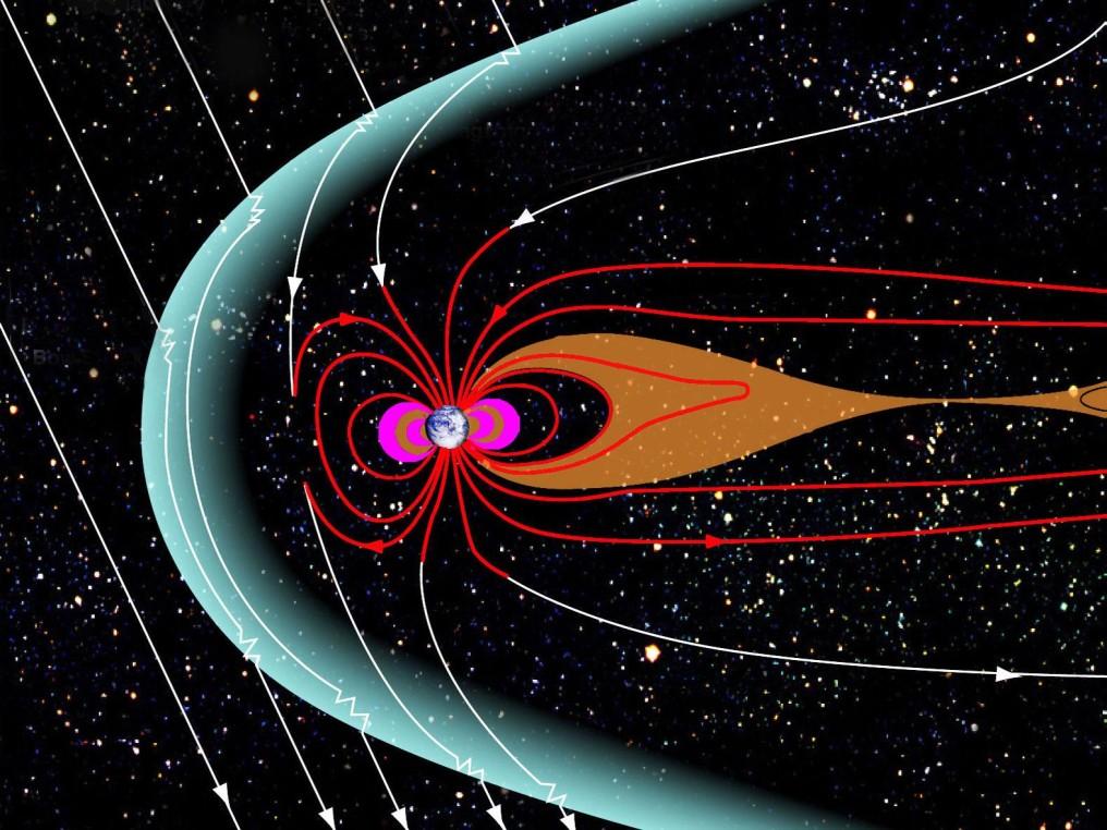
11 The Magnetosphere 11
12 Skywave Radio waves appear to be reflected back to earth by the E or F Layers In fact, due to refraction. The velocity of the radio wave is changed as it passes through the ionised layer In the ionised layer, the refractive index (n) < 1 and the wave speeds up, bending away from the normal As ionisation increases n decreases and wave bends further and further until it reflects back towards earth For any given frequency, the amount of refraction depends on ionisation density and angle of incidence 12

13 Reflection by Refraction 13
14 Refractive Index of Cold Magnetised Plasma Appleton Hartree Formula n is refractive index ± means there are two solutions i.e Two differing refractive indices Birefringent Ө angle between wave vector and ambient magnetic field 14
15 Why Two Solutions? Plasma Physicists forgive me! Free electrons are moved by the magnetic field Gyrofrequency MHz Ions are much heavier and move correspondingly slower Electric Field parallel to Magnetic Field - electrons move more easily Electric Field perpendicular to Magnetic Field electrons "push back" 15
16 Magneto-Ionic Splitting On entering the birefringent ionosphere an incident radio wave splits into two eliptically polarised waves The exact polarisation depends on the angle between the wave vector and the magnetic field In the unusual case that the wave vector is parallel to the magnetic field the two waves will be counter-rotating circular polarisation When wave vector and magnetic field are not parallel Ordinary Wave (O) behaves as if there is no magnetic field Extraordinary Wave (X) modified by magnetic field 16

17 Did you get that? 17

18 Not Always Great Circle Not Always Reciprocal 18
19 Critical Frequency In ionised layer, refractive index depends on amount of ionisation and frequency As frequency increases, n increases and amount of refraction decreases Critical Frequency = Highest frequency which will reflect vertically from the ionosphere Different critical frequencies for different layers, f 0 E, f 0 F1, f 0 F2 etc. Different critical frequencies for the O-mode and the X-mode Vertical Ionogram from HAARP Alaska Red O-mode Green X-mode 19
20 Vertical Ionogram Alaska 20
21 Vertical Ionogram UK 21


22 Oblique Frequency Increasing Angle Increasing 22
23 Pederson Rays 23
24 MUF, OWF and LUF Maximum Usable Frequency (MUF) Calculated from (Predicted) Critical Frequency Depends on Location and Range Critical Frequency depends on Ionospheric Conditions Actual maximum operating frequency can be higher Optimum Working Frequency (OWF) 0.85 x MUF Predicted 90% Probability of propagation Lowest Usable Frequency (LUF) Depends on Location and Range Depends on (Predicted) Ionospheric Conditions Depends on Transmitter Power Depends on Antenna Gain (Directivity) 24
 http://www.rcru.rl.ac.")
25 Oblique Ionogram (3000 km, Sun Spot Min.) 25
26 Interpret Ionogram 26
27 Many Modes 27
 Aurora NOT a sphere Moving Lumpy \"Tilted\" Travelling Ionospheric Disturbances (TIDs)")
28 Flimsy Ionosphere Mass ~ 1 tonne Diameter ~ 13,000 km Density ~ 1/10 15 (1/(1000* * ) ) Air at Sea Level Hugely susceptible to disturbances Magnetic Solar Wind Weather (below) Aurora NOT a sphere Moving Lumpy "Tilted" Travelling Ionospheric Disturbances (TIDs) 28
29 Distortion The signal that is received is not very often the same as the signal that was transmitted! Fading Groundwave / Skywave interaction Multiple skywave paths (including magneto-ionic splitting) Movement of ionospheric irregularities Spread-F / Aurora Frequency Shift and Frequency Spread (Doppler) Time Dispersion and Delay Spread 29
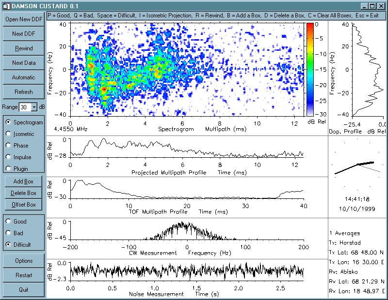
30 DAMSON 30
Chapter 7 HF Propagation. Ionosphere Solar Effects Scatter and NVIS
 Chapter 7 HF Propagation Ionosphere Solar Effects Scatter and NVIS Ionosphere and Layers Radio Waves Bent by the Ionosphere Daily variation of Ionosphere Layers Ionospheric Reflection Conduction by electrons
4/29/2012. General Class Element 3 Course Presentation. Radio Wave Propagation. Radio Wave Propagation. Radio Wave Propagation.
 General Class Element 3 Course Presentation ti ELEMENT 3 SUB ELEMENTS General Licensing Class Subelement G3 3 Exam Questions, 3 Groups G1 Commission s Rules G2 Operating Procedures G3 G4 Amateur Radio
Chapter 6 Propagation
 Chapter 6 Propagation Al Penney VO1NO Objectives To become familiar with: Classification of waves wrt propagation; Factors that affect radio wave propagation; and Propagation characteristics of Amateur
Maximum Usable Frequency
 Maximum Usable Frequency 15 Frequency (MHz) 10 5 0 Maximum Usable Frequency Usable Frequency Window Lowest Usable Frequency Solar Flare 6 12 18 24 Time (Hours) Radio Blackout Usable Frequency Window Ken
General Classs Chapter 7
 General Classs Chapter 7 Radio Wave Propagation Bob KA9BHD Eric K9VIC Learning Objectives Teach you enough to get all the propagation questions right during the VE Session Learn a few things from you about
Polarization orientation of the electric field vector with respect to the earth s surface (ground).
.") Free space propagation of electromagnetic waves is often called radio-frequency (rf) propagation or simply radio propagation. The earth s atmosphere, as medium introduces losses and impairments to the
Free space propagation of electromagnetic waves is often called radio-frequency (rf) propagation or simply radio propagation. The earth s atmosphere, as medium introduces losses and impairments to the
Reading 28 PROPAGATION THE IONOSPHERE
 Reading 28 Ron Bertrand VK2DQ http://www.radioelectronicschool.com PROPAGATION THE IONOSPHERE The ionosphere is a region of the upper atmosphere extending from a height of about 60 km to greater than 500
Space Weather and Propagation JANUARY 14, 2017
 Space Weather and Propagation MARTIN BUEHRING -KB4MG ELEC T R ICAL ENGINEER, A M AT EUR EXTRA CLASS LICENSE HOLDER JANUARY 14, 2017 Why know about Space Weather? Our SUN has an enormous affect not only
Terry G. Glagowski W1TR / AFA1DI
 The Ionogram and Radio Propagation By Terry G. Glagowski / W1TR / AFA1DI - 9/29/2017 9:46 AM Excerpts from a presentation by Tom Carrigan / NE1R / AFA1ID by Terry G. Glagowski W1TR / AFA1DI Knowledge of
OBJECTIVES: PROPAGATION INTRO RADIO WAVES POLARIZATION LINE OF SIGHT, GROUND WAVE, SKY WAVE IONOSPHERE REGIONS PROPAGATION, HOPS, SKIPS ZONES THE
 WAVE PROPAGATION OBJECTIVES: PROPAGATION INTRO RADIO WAVES POLARIZATION LINE OF SIGHT, GROUND WAVE, SKY WAVE IONOSPHERE REGIONS PROPAGATION, HOPS, SKIPS ZONES THE IONOSPHERIC LAYERS ABSORPTION AND FADING
Ionospheric Sounders What are they? How can you use them?
 Ionospheric Sounders What are they? How can you use them? History of the ionosphere Jan. 1901 Marconi sends signals from Isle of Wight to The Lizard, Cornwall Dec. 1901 Marconi crosses Atlantic, from Poldhu
NVIS PROPAGATION THEORY AND PRACTICE
 NVIS PROPAGATION THEORY AND PRACTICE Introduction Near-Vertical Incident Skywave (NVIS) propagation is a mode of HF operation that utilizes a high angle reflection off the ionosphere to fill in the gap
Ionospheric Propagation
 Ionospheric Propagation Page 1 Ionospheric Propagation The ionosphere exists between about 90 and 1000 km above the earth s surface. Radiation from the sun ionizes atoms and molecules here, liberating
Plasma in the ionosphere Ionization and Recombination
 Plasma in the ionosphere Ionization and Recombination Jamil Muhammad Supervisor: Professor kjell Rönnmark 1 Contents: 1. Introduction 3 1.1 History.3 1.2 What is the ionosphere?...4 2. Ionization and recombination.5
If maximum electron density in a layer is less than n', the wave will penetrate the layer
 UNIT-7 1. Briefly the describe the terms related to the sky wave propagation: virtual heights, critical frequency, maximum usable frequency, skip distance and fading? Ans: Sky wave propagation: It is also
High Frequency Propagation (and a little about NVIS)
") High Frequency Propagation (and a little about NVIS) Tom McDermott, N5EG August 18, 2010 September 2, 2010 Updated: February 7, 2013 The problem Radio waves, like light waves, travel in ~straight lines.
High Frequency Propagation (and a little about NVIS) Tom McDermott, N5EG August 18, 2010 September 2, 2010 Updated: February 7, 2013 The problem Radio waves, like light waves, travel in ~straight lines.
# DEFINITIONS TERMS. 2) Electrical energy that has escaped into free space. Electromagnetic wave
 Electrical energy that has escaped into free space. Electromagnetic wave") CHAPTER 14 ELECTROMAGNETIC WAVE PROPAGATION # DEFINITIONS TERMS 1) Propagation of electromagnetic waves often called radio-frequency (RF) propagation or simply radio propagation. Free-space 2) Electrical
CHAPTER 14 ELECTROMAGNETIC WAVE PROPAGATION # DEFINITIONS TERMS 1) Propagation of electromagnetic waves often called radio-frequency (RF) propagation or simply radio propagation. Free-space 2) Electrical
Antennas and Propagation Chapters T4, G7, G8 Antenna Fundamentals, More Antenna Types, Feed lines and Measurements, Propagation
 Antennas and Propagation Chapters T4, G7, G8 Antenna Fundamentals, More Antenna Types, Feed lines and Measurements, Propagation =============================================================== Antenna Fundamentals
Radiation and Particles from the. Sun
 2017 Radiation and Particles from the Photons Sun Photons (300000km/s ~ 8m 20s) radio waves, infra red, visible light, ultra violet, x-ray, x galactic waves, Solar Flux (30000km/s ~ 8m 20s) The 10.7 cm
Lesson 12: Signal Propagation
 Lesson 12: Signal Propagation Preparation for Amateur Radio Technician Class Exam Topics HF Propagation Ground-wave Sky-wave Ionospheric regions VHF/UHF Propagation Line-of-sight Tropospheric Bending and
Radar Reprinted from "Waves in Motion", McGourty and Rideout, RET 2005
 Radar Reprinted from "Waves in Motion", McGourty and Rideout, RET 2005 What is Radar? RADAR (Radio Detection And Ranging) is a way to detect and study far off targets by transmitting a radio pulse in the
1. Terrestrial propagation
 Rec. ITU-R P.844-1 1 RECOMMENDATION ITU-R P.844-1 * IONOSPHERIC FACTORS AFFECTING FREQUENCY SHARING IN THE VHF AND UHF BANDS (30 MHz-3 GHz) (Question ITU-R 218/3) (1992-1994) Rec. ITU-R PI.844-1 The ITU
RADIOWAVE PROPAGATION
 RADIOWAVE PROPAGATION Physics and Applications CURT A. LEVIS JOEL T. JOHNSON FERNANDO L. TEIXEIRA The cover illustration is part of a figure from R.C. Kirby, "Introduction," Lecture 1 in NBS Course in
RF Propagation. By Tim Kuhlman, PE KD7RUS
 RF Propagation By Tim Kuhlman, PE KD7RUS Purpose of this Seminar In this seminar we will attempt to answer the following questions: What is RF propagation? What are the different types of propagation?
Study of small scale plasma irregularities. Đorđe Stevanović
 Study of small scale plasma irregularities in the ionosphere Đorđe Stevanović Overview 1. Global Navigation Satellite Systems 2. Space weather 3. Ionosphere and its effects 4. Case study a. Instruments
S.R.M. Institute of Science & Technology Deemed University School of Electronics & Communication Engineering
 S.R.M. Institute of Science & Technology Deemed University School of Electronics & Communication Engineering Question Bank Subject Code : EC401 Subject Name : Antennas and Wave Propagation Year & Sem :
Introduction To The Ionosphere
 Introduction To The Ionosphere John Bosco Habarulema Radar School 12 13 September 2015, SANSA, What is a radar? This being a radar school... RAdio Detection And Ranging To determine the range, R, R=Ct/2,
Wave Propagation and Antenna Engineering
 Wave Propagation and Antenna Engineering Wave Propagation and Antenna Engineering SANJAY KUMAR Air Commodore (Retd.) Former AOC, 9 BRD, IAF Pune and Former Principal Adviser Defence Avionics Research
3 Methods of radiocommunication
 + + & & * * ) ) From the ITU Emergency Telecommunications handbook; prepared for the 54 th JOTA 2011. 3 Methods of radiocommunication 3.1 Frequencies Radio frequencies should be selected according to propagation
Chapter 15: Radio-Wave Propagation
 Chapter 15: Radio-Wave Propagation MULTIPLE CHOICE 1. Radio waves were first predicted mathematically by: a. Armstrong c. Maxwell b. Hertz d. Marconi 2. Radio waves were first demonstrated experimentally
Ionospheric Absorption
 Ionospheric Absorption Prepared by Forrest Foust Stanford University, Stanford, CA IHY Workshop on Advancing VLF through the Global AWESOME Network VLF Injection Into the Magnetosphere Earth-based VLF
AN INTRODUCTION TO VHF/ UHF PROPAGATION. Paul Wilton, M1CNK
 AN INTRODUCTION TO VHF/ UHF PROPAGATION Paul Wilton, M1CNK OVERVIEW Introduction Propagation Basics Propagation Modes Getting Started in 2m DX INTRODUCTION QRV on 2m SSB since Aug 1998, on 6m since Jan
A first study into the propagation of 5 MHz (60 m) signals using the South African ionosonde network
 signals using the South African ionosonde network") A first study into the propagation of 5 MHz (60 m) signals using the South African ionosonde network Hannes Coetzee, B. Eng. (Electronics), M. Sc. (Physics), ZS6BZP The SARL has purchased two 5 MHz test
A first study into the propagation of 5 MHz (60 m) signals using the South African ionosonde network Hannes Coetzee, B. Eng. (Electronics), M. Sc. (Physics), ZS6BZP The SARL has purchased two 5 MHz test
A Review of WICEN HF Communications Capability
 A Review of WICEN HF Communications Capability Abstract During a recent event, some problems were experienced with the traditional lower HF band communications often used for WICEN events. This paper describes
14. COMMUNICATION SYSTEM
 14. COMMUNICATION SYSTEM SYNOPSIS : INTRODUCTION 1. The exchange of information between a sender and receiver is called communication. 2. The arrangement of devices to transfere the information is called
EEM.Ant. Antennas and Propagation
 EEM.ant/0304/08pg/Req: None 1/8 UNIVERSITY OF SURREY Department of Electronic Engineering MSc EXAMINATION EEM.Ant Antennas and Propagation Duration: 2 Hours Spring 2003/04 READ THESE INSTRUCTIONS Answer
Plasma in the Ionosphere Ionization and Recombination
 Plasma in the Ionosphere Ionization and Recombination Agabi E Oshiorenoya July, 2004 Space Physics 5P Umeå Universitet Department of Physics Umeå, Sweden Contents 1 Introduction 6 2 Ionization and Recombination
Technician License Course Chapter 4
 Technician License Course Chapter 4 Propagation, Basic Antennas, Feed lines & SWR K0NK 26 Jan 18 The Antenna System Antenna: Facilitates the sending of your signal to some distant station. Feed line: Connects
Amateur Radio License. Propagation and Antennas
 Amateur Radio License Propagation and Antennas Todays Topics Propagation Antennas Propagation Modes Ground wave Low HF and below, ground acts as waveguide Line-of-Sight (LOS) VHF and above, radio waves
RF Propagation. By Tim Kuhlman, PE KD7RUS
 RF Propagation By Tim Kuhlman, PE KD7RUS Purpose of this Seminar In this seminar we will attempt to answer the following questions: What is RF propagation? What are the different types of propagation?
Using the Radio Spectrum to Understand Space Weather
 Using the Radio Spectrum to Understand Space Weather Ray Greenwald Virginia Tech Topics to be Covered What is Space Weather? Origins and impacts Analogies with terrestrial weather Monitoring Space Weather
Introduction to HF Propagation. Rick Fletcher, W7YP FVARC November 20, 2018
 Introduction to HF Propagation Rick Fletcher, W7YP FVARC November 20, 2018 Topics The HF Bands How HF propagation works Overview by HF band Sources of solar and propagation information Working HF during
FCC Technician License Course
 FCC Technician License Course 2014-2018 FCC Element 2 Technician Class Question Pool Presented by: Tamiami Amateur Radio Club (TARC) WELCOME To the third of 4, 3-hour classes presented by TARC to prepare
Propagation Tool.
 Propagation Propagation Tool http://www.hamqsl.com/solar.html The Ionosphere is made up of several layers at varying heights above the ground: The lowest level is the D Layer (37 to 56 miles), which
Topics in Propagation
 Topics in Propagation Extra Class Course Spring 2013 Andy Durbin k3wyc Propagation The magic that allows a signal to travel between the transmitting antenna and the receiving antenna. This course is limited
right during the VE Session Have fun Bob, KA9BH Eric, K9VIC
 Radio Wave Propagation Teach you enough to get all right during the VE Session Learn a few things from you Have fun Finish everything on time (if the propagation questions about your experiences not a
Global Maps with Contoured Ionosphere Properties Some F-Layer Anomalies Revealed By Marcel H. De Canck, ON5AU. E Layer Critical Frequencies Maps
 Global Maps with Contoured Ionosphere Properties Some F-Layer Anomalies Revealed By Marcel H. De Canck, ON5AU In this column, I shall handle some possibilities given by PROPLAB-PRO to have information
Storms in Earth s ionosphere
 Storms in Earth s ionosphere Archana Bhattacharyya Indian Institute of Geomagnetism IISF 2017, WSE Conclave; Anna University, Chennai Earth s Ionosphere Ionosphere is the region of the atmosphere in which
Sw earth Dw Direct wave GRw Ground reflected wave Sw Surface wave
 WAVE PROPAGATION By Marcel H. De Canck, ON5AU Electromagnetic radio waves can propagate in three different ways between the transmitter and the receiver. 1- Ground waves 2- Troposphere waves 3- Sky waves
2 Propagation mechanisms responsible for propagation at frequencies above the basic MUF
 1 REPORT ITU-R P.2011 PROPAGATION AT FREQUENCIES ABOVE THE BASIC MUF (1997) 1 Introduction Recommendation ITU-R P.373 defines the basic MUF as the highest frequency by which a radio wave can propagate
Dartmouth College SuperDARN Radars
 Dartmouth College SuperDARN Radars Under the guidance of Thayer School professor Simon Shepherd, a pair of backscatter radars were constructed in the desert of central Oregon over the Summer and Fall of
Ionospheric sounding at the RMI Geophysical Centre in Dourbes: digital ionosonde performance and ionospheric monitoring service applications
 Solar Terrestrial Centre of Excellence Ionospheric sounding at the RMI Geophysical Centre in Dourbes: digital ionosonde performance and ionospheric monitoring service applications S. Stankov, T. Verhulst,
Wave & Electromagnetic Spectrum Notes
 Wave & Electromagnetic Spectrum Notes December 17, 2011 I.) Properties of Waves A) Wave: A periodic disturbance in a solid, liquid or gas as energy is transmitted through a medium ( Waves carry energy
CRITICAL FREQUENCY By Marcel H. De Canck, ON5AU
 CRITICAL FREQUENCY By Marcel H. De Canck, ON5AU Before reading onward, it would be good to refresh your knowledge about refraction rules in the section on Refraction of the earlier "Wave Propagation Direction
High-frequency radio wave absorption in the D- region
 Utah State University From the SelectedWorks of David Smith Spring 2017 High-frequency radio wave absorption in the D- region David Alan Smith, Utah State University This work is licensed under a Creative
PoS(2nd MCCT -SKADS)003
003") The Earth's ionosphere: structure and composition. Dispersive effects, absorption and emission in EM wave propagation 1 Observatorio Astronómico Nacional Calle Alfonso XII, 3; E-28014 Madrid, Spain E-mail:
The Earth's ionosphere: structure and composition. Dispersive effects, absorption and emission in EM wave propagation 1 Observatorio Astronómico Nacional Calle Alfonso XII, 3; E-28014 Madrid, Spain E-mail:
UNIT V PROPAGATION The three basic types of propagation: Sky Wave Propagation: Space Wave Propagation: Ground Wave Propagation: Propagation of Waves
 UNIT V PROPAGATION The three basic types of propagation: Ground wave, space wave and sky wave propagation. Sky Wave Propagation: Structure of the ionosphere Effective dielectric constant of ionized region
CHAPTER 6. Propagation
 CHAPTER 6 Propagation TOC: INTRO RADIO WAVES POLARIZATION LINE OF SIGHT, GROUND & SKY WAVES IONOSPHERE REGIONS IONOSPHERIC LAYERS PROPAGATION, HOPS, SKIPS ZONES ABSORPTION AND FADING SOLAR ACTIVITY AND
imaging of the ionosphere and its applications to radio propagation Fundamentals of tomographic Ionospheric Tomography I: Ionospheric Tomography I:
 Ionospheric Tomography I: Ionospheric Tomography I: Fundamentals of tomographic imaging of the ionosphere and its applications to radio propagation Summary Introduction to tomography Introduction to tomography
Daytime modelling of VLF radio waves over land and sea, comparison with data from DEMETER Satellite
 Daytime modelling of VLF radio waves over land and sea, comparison with data from DEMETER Satellite S. G. Meyer 1,2, A. B. Collier 1,2, C. J. Rodger 3 1 SANSA Space Science, Hermanus, South Africa 2 School
RADAR DEVELOPMENT BASIC CONCEPT OF RADAR WAS DEMONSTRATED BY HEINRICH. HERTZ VERIFIED THE MAXWELL RADAR.
 1 RADAR WHAT IS RADAR? RADAR (RADIO DETECTION AND RANGING) IS A WAY TO DETECT AND STUDY FAR OFF TARGETS BY TRANSMITTING A RADIO PULSE IN THE DIRECTION OF THE TARGET AND OBSERVING THE REFLECTION OF THE
RADIO WAVE PROPAGATION
 CHAPTER 2 RADIO WAVE PROPAGATION Radio direction finding (RDF) deals with the direction of arrival of radio waves. Therefore, it is necessary to understand the basic principles involved in the propagation
RECOMMENDATION ITU-R P HF PROPAGATION PREDICTION METHOD* (Question ITU-R 223/3)
") Rec. ITU-R P.533-6 1 RECOMMENDATION ITU-R P.533-6 HF PROPAGATION PREDICTION METHOD* (Question ITU-R 223/3) Rec. ITU-R P.533-6 (1978-1982-1990-1992-1994-1995-1999) The ITU Radiocommunication Assembly, considering
Rec. ITU-R P.533-6 1 RECOMMENDATION ITU-R P.533-6 HF PROPAGATION PREDICTION METHOD* (Question ITU-R 223/3) Rec. ITU-R P.533-6 (1978-1982-1990-1992-1994-1995-1999) The ITU Radiocommunication Assembly, considering
RECOMMENDATION ITU-R P HF propagation prediction method *
 Rec. ITU-R P.533-7 1 RECOMMENDATION ITU-R P.533-7 HF propagation prediction method * (Question ITU-R 3/3) (1978-198-1990-199-1994-1995-1999-001) The ITU Radiocommunication Assembly, considering a) that
Antennas and Propagation. Chapter 5
 Antennas and Propagation Chapter 5 Introduction An antenna is an electrical conductor or system of conductors Transmission - radiates electromagnetic energy into space Reception - collects electromagnetic
Electron acceleration and ionization fronts induced by high frequency plasma turbulence
 Eliasson, Bengt (2014) Electron acceleration and ionization fronts induced by high frequency plasma turbulence. In: 41st IOP Plasma Physics Conference, 2014-04-14-2014-04-17, Grand Connaught Rooms., This
Antennas & Propagation. CSG 250 Fall 2007 Rajmohan Rajaraman
 Antennas & Propagation CSG 250 Fall 2007 Rajmohan Rajaraman Introduction An antenna is an electrical conductor or system of conductors o Transmission - radiates electromagnetic energy into space o Reception
Section 1 Wireless Transmission
 Part : Wireless Communication! section : Wireless Transmission! Section : Digital modulation! Section : Multiplexing/Medium Access Control (MAC) Section Wireless Transmission Intro. to Wireless Transmission
Chapter 1. Introduction. 1.1 Background and Motivation Ionospheric Propagation
 Chapter 1 Introduction 1.1 Background and Motivation Guglielmo Marconi conducted an experiment in 1864 to demonstrate that an electromagnetic signal could be transmitted between two relatively distant
1. What are the applications of loop antenna? (May2011) 2. Define Pattern Multiplication (May2011)
 2. Define Pattern Multiplication (May2011)") UNIT-II WIRE ANTENNAS AND ANTENNA ARRAYS 1. What are the applications of loop antenna? (May2011) 2. Define Pattern Multiplication (May2011) 3. A uniform linear array contains 50 isotropic radiation with
UNIT-II WIRE ANTENNAS AND ANTENNA ARRAYS 1. What are the applications of loop antenna? (May2011) 2. Define Pattern Multiplication (May2011) 3. A uniform linear array contains 50 isotropic radiation with
Antenna & Propagation. Basic Radio Wave Propagation
 For updated version, please click on http://ocw.ump.edu.my Antenna & Propagation Basic Radio Wave Propagation by Nor Hadzfizah Binti Mohd Radi Faculty of Electric & Electronics Engineering hadzfizah@ump.edu.my
Space Weather and the Ionosphere
 Dynamic Positioning Conference October 17-18, 2000 Sensors Space Weather and the Ionosphere Grant Marshall Trimble Navigation, Inc. Note: Use the Page Down key to view this presentation correctly Space
Broad Principles of Propagation 4C4
 Broad Principles of Propagation ledoyle@tcd.ie 4C4 Starting at the start All wireless systems use spectrum, radiowaves, electromagnetic waves to function It is the fundamental and basic ingredient of
Effects of magnetic storms on GPS signals
 Effects of magnetic storms on GPS signals Andreja Sušnik Supervisor: doc.dr. Biagio Forte Outline 1. Background - GPS system - Ionosphere 2. Ionospheric Scintillations 3. Experimental data 4. Conclusions
HF Skywave ITU-R P Gets a Re-Write. July Pierre Missud Avadh Nandra. RF Modeling with Precision
 HF Skywave ITU-R P.533-9 Gets a Re-Write July 2008 Pierre Missud Avadh Nandra RF Modeling with Precision 0 0 HF Skywave ITU-R P. 533-9 gets a re-write HF skywave propagation was introduced to this world
Determination of the correlation distance for spaced antennas on multipath HF links and implications for design of SIMO and MIMO systems.
 Determination of the correlation distance for spaced antennas on multipath HF links and implications for design of SIMO and MIMO systems. Hal J. Strangeways, School of Electronic and Electrical Engineering,
ESS 7 Lectures 15 and 16 November 3 and 5, The Atmosphere and Ionosphere
 ESS 7 Lectures 15 and 16 November 3 and 5, 2008 The Atmosphere and Ionosphere The Earth s Atmosphere The Earth s upper atmosphere is important for groundbased and satellite radio communication and navigation.
Electromagnetic Waves
 Electromagnetic Waves What is an Electromagnetic Wave? An EM Wave is a disturbance that transfers energy through a field. A field is a area around an object where the object can apply a force on another
The Earth s Atmosphere
 ESS 7 Lectures 15 and 16 May 5 and 7, 2010 The Atmosphere and Ionosphere The Earth s Atmosphere The Earth s upper atmosphere is important for groundbased and satellite radio communication and navigation.
Antennas and Propagation. Chapter 5
 Antennas and Propagation Chapter 5 Introduction An antenna is an electrical conductor or system of conductors Transmission - radiates electromagnetic energy into space Reception - collects electromagnetic
REFLECTION AND TRANSMISSION IN THE IONOSPHERE CONSIDERING COLLISIONS IN A FIRST APPROXIMATION
 Progress In Electromagnetics Research Letters, Vol. 1, 93 99, 2008 REFLECTION AND TRANSMISSION IN THE IONOSPHERE CONSIDERING COLLISIONS IN A FIRST APPROXIMATION A. Yesil and M. Aydoğdu Department of Physics
Ionospheric Impacts on UHF Space Surveillance. James C. Jones Darvy Ceron-Gomez Dr. Gregory P. Richards Northrop Grumman
 Ionospheric Impacts on UHF Space Surveillance James C. Jones Darvy Ceron-Gomez Dr. Gregory P. Richards Northrop Grumman CONFERENCE PAPER Earth s atmosphere contains regions of ionized plasma caused by
UNIT Derive the fundamental equation for free space propagation?
 UNIT 8 1. Derive the fundamental equation for free space propagation? Fundamental Equation for Free Space Propagation Consider the transmitter power (P t ) radiated uniformly in all the directions (isotropic),
AGF-216. The Earth s Ionosphere & Radars on Svalbard
 AGF-216 The Earth s Ionosphere & Radars on Svalbard Katie Herlingshaw 07/02/2018 1 Overview Radar basics what, how, where, why? How do we use radars on Svalbard? What is EISCAT and what does it measure?
Ray Tracing Analysis for the mid-latitude SuperDARN HF radar at Blackstone incorporating the IRI-2007 model
 Ray Tracing Analysis for the mid-latitude SuperDARN HF radar at Blackstone incorporating the IRI-2007 model Nitya Ravindran Varrier Thesis submitted to the faculty of the Virginia Polytechnic Institute
Summary of Findings Associated with the 5 MHz Experiment. Marcus C. Walden G0IJZ Space Weather Knowledge Exchange Workshop: HAMSCI UK 13 October 2017
 Summary of Findings Associated with the 5 MHz Experiment Marcus C. Walden G0IJZ Space Weather Knowledge Exchange Workshop: HAMSCI UK 13 October 2017 Overview of Presentation Introduction The 5 MHz Experiment
A technique for calculating ionospheric Doppler shifts from standard ionograms suitable for scientific, HF communication, and OTH radar applications
 RADIO SCIENCE, VOL. 44,, doi:10.1029/2009rs004210, 2009 A technique for calculating ionospheric Doppler shifts from standard ionograms suitable for scientific, HF communication, and OTH radar applications
Antennas and Propagation
 Mobile Networks Module D-1 Antennas and Propagation 1. Introduction 2. Propagation modes 3. Line-of-sight transmission 4. Fading Slides adapted from Stallings, Wireless Communications & Networks, Second
Get Discount Coupons for your Coaching institute and FREE Study Material at COMMUNICATION SYSTEMS
 COMMUNICATION SYSTEMS 1. BASICS OF COMMUNICATION 2. AMPLITUDE MODULATION Get Discount Coupons for your Coaching institute and FREE Study Material at www.pickmycoaching.com 1 BASICS OF COMMUNICATION 1.
A Neural Network tool for the interpolation of fof2 data in the presence of sporadic E layer
 A Neural Network tool for the interpolation of fof data in the presence of sporadic E layer Haris Haralambous, Antonis Ioannou and Harris Papadopoulos Computer Science and Engineering Department, Frederick
Name: Date Due: Waves. Physical Science Chapter 6
 Date Due: Waves Physical Science Chapter 6 Waves 1. Define the following terms: a. periodic motion = b. cycle= c. period= d. mechanical wave= e. medium = f. transverse wave = g. longitudinal wave= h. surface
Chapter 1: Telecommunication Fundamentals
 Chapter 1: Telecommunication Fundamentals Block Diagram of a communication system Noise n(t) m(t) Information (base-band signal) Signal Processing Carrier Circuits s(t) Transmission Medium r(t) Signal
4/18/2012. Supplement T3. 3 Exam Questions, 3 Groups. Amateur Radio Technician Class
 Amateur Radio Technician Class Element 2 Course Presentation ti ELEMENT 2 SUB-ELEMENTS Technician Licensing Class Supplement T3 Radio Wave Characteristics 3 Exam Questions, 3 Groups T1 - FCC Rules, descriptions
Antennas and Propagation. Prelude to Chapter 4 Propagation
 Antennas and Propagation Prelude to Chapter 4 Propagation Introduction An antenna is an electrical conductor or system of conductors for: Transmission - radiates electromagnetic energy into space (involves
Antennas and Propagation
 Antennas and Propagation Chapter 5 Introduction An antenna is an electrical conductor or system of conductors Transmission - radiates electromagnetic energy into space Reception - collects electromagnetic
Radio Communication. Presentation created by: András Balogh
 Radio Communication Presentation created by: András Balogh AM and FM The goal is to transmit a modulating signal S(t) via a wave sin(ωt). In case of AM, the product of the modulation is f(t)=(a+s(t))*sin(ωt);
Currents, Electrojets and Instabilities. John D Sahr Electrical Engineering University of Washington 19 June 2016
 Currents, Electrojets and Instabilities John D Sahr Electrical Engineering University of Washington 19 June 2016 Outline The two main sources of large scale currents in the ionosphere: solar-wind/magnetosphere,
The EISCAT Heating Facility
 The EISCAT Heating Facility Michael Rietveld EISCAT Tromsø, Norway EISCAT radar school, 30 Aug-4 Sept, 2010, Sodankylä 1 Outline Description of the hardware Antenna beams Practical details- power levels
RECOMMENDATION ITU-R P Prediction of sky-wave field strength at frequencies between about 150 and khz
 Rec. ITU-R P.1147-2 1 RECOMMENDATION ITU-R P.1147-2 Prediction of sky-wave field strength at frequencies between about 150 and 1 700 khz (Question ITU-R 225/3) (1995-1999-2003) The ITU Radiocommunication
Monitoring Solar flares by Radio Astronomy
 Monitoring Solar flares by Radio Astronomy Presented at the RASC Sunshine Coast Centre, February 8th, 2013, 7:30 pm Mike Bradley, RASC Sunshine Coast Centre Solar flares Solar flares occur when sunspots