CHAPTER 6. Propagation
|
|
|
- Gerald Parks
- 5 years ago
- Views:
Transcription
1 CHAPTER 6 Propagation
2 TOC: INTRO RADIO WAVES POLARIZATION LINE OF SIGHT, GROUND & SKY WAVES IONOSPHERE REGIONS IONOSPHERIC LAYERS PROPAGATION, HOPS, SKIPS ZONES ABSORPTION AND FADING SOLAR ACTIVITY AND SUN SPOTS MF, HF CRITICAL FREQUENCIES UHF, VHF, SPORADIC E, AURORAS, DUCTING SCATTER, HF, VHF,UHF BEACONS SAMPLE QUESTIONS Major General Urquhart: My communications are completely broken down. Do you really believe any of that can be helped by a cup of tea? Corporal Hancock: Couldn't hurt, sir -Arnhem 1944
3
4 PROPAGATION - INTRO Propagation: How radio waves travel from point A to point B; and the events occurring in the transmission path that affect the communications between the points, stations, or operators. When the electrons in a conductor, (antenna wire) are made to oscillate back and forth, Electromagnetic Waves (EM waves) are produced. These waves radiate outwards from the source at the speed of light, 300 million meters per second. Light waves (waves we see) and radio waves (waves we hear)are both EM waves, differing only in frequency and wavelength.

5 PROPAGATION INTRO CONT D EM waves travel in straight lines, unless acted upon by some outside force. They travel faster through a vacuum than through any other medium. As EM waves spread out from the point of origin, they decrease in strength in what is described as an "inverse square relationship". For example: a signal 2 km from its starting point will be only 1/4 as strong as that 1 km from the source. A signal 3 km from the source will be only 1/9 that at the 1 km point. HOWEVER.. Modern receivers are very sensitive and extremely small power provides usable signals. Waves can be received many thousands of kilometers from the transmitting station. For Example, Voyager 2 transmitted signals over many billions of kilometers from outer space with only 25 W of power!
6 RADIO WAVES
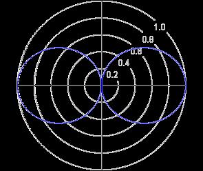
7 RADIO WAVES x Electric Field, E y Magnetic Field, H z Direction of Propagation Electromagnetic radiation comprises both an Electric and a Magnetic Field. The two fields are at right-angles to each other and the direction of propagation is at right-angles to both fields. The Plane of the Electric Field defines the Polarisation of the wave.

8 RADIO WAVES CONT D Two types of waves: Transverse and Longitudinal Transverse waves: vibration is from side to side; that is, at right angles to the direction in which they travel A guitar string vibrates with transverse motion. EM waves are always transverse.


9 RADIO WAVES CONT D Longitudinal waves: Vibration is parallel to the direction of propagation. Sound and pressure waves are longitudinal and oscillate back and forth as vibrations are along or parallel to their direction of travel A wave in a "slinky" is a good visualization
10 POLARIZATION The polarization of an antenna is the orientation of the electric field with respect to the Earth's surface and is determined by the physical structure of the antenna and by its orientation Radio waves from a vertical antenna will usually be vertically polarized. Radio waves from a horizontal antenna are usually horizontally polarized.
11 Direction of Propagation Direction of Propagation

12 Vertically polarized omnidirectional dipole antenna Horizontally polarized directional yagi antenna
13 RADIO WAVES CONT D RADIO WAVES SPACE GROUND SKY REFLECTED DIRECT SURFACE
14 LINE OF SIGHT, GROUND WAVE, SKY WAVE Ground Wave is a Surface Wave that propagates or travels close to the surface of the Earth. Line of Sight (Ground Wave or Direct Wave) is propagation of waves travelling in a straight line. These waves are deviated (reflected) by obstructions and cannot travel over the horizon or behind obstacles. Most common direct wave occurs with VHF modes and higher frequencies. At higher frequencies and in lower levels of the atmosphere, any obstruction between the transmitting antenna and the receiving antenna will block the signal, just like the light that the eye senses. Space Waves: travel directly from an antenna to another without reflection on the ground. Occurs when both antennas are within line of sight of each another, distance is longer that line of sight because most space waves bend near the ground and follow practically a curved path. Antennas must display a very low angle of emission in order that all the power is radiated in direction of the horizon instead of escaping in the sky. A high gain and horizontally polarized antenna is thus highly recommended. Sky Wave (Skip/ Hop/ Ionospheric Wave) is the propagation of radio waves bent (refracted) back to the Earth's surface by the ionosphere. HF radio communication (3 and 30 MHz) is a result of sky wave propagation.

15 LINE OF SIGHT, GROUND WAVE, SKY WAVE

16 KNOWLEDGE CHECK
17 PROPAGATION, HOPS, SKIPS ZONES
 from the sun on the upper atmosphere.")
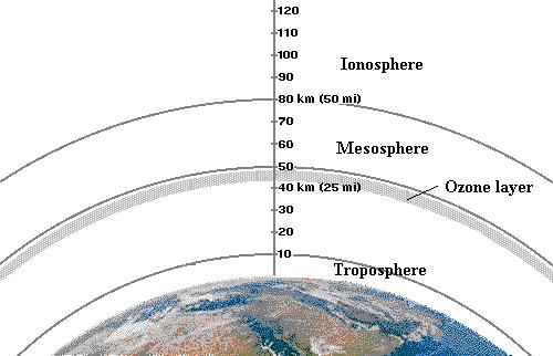
18 IONOSPHERE REGIONS The ionosphere is the uppermost part of the atmosphere and is ionized by solar radiation. Ionization is the conversion of atoms or molecules into an ion by light (heating up or charging) from the sun on the upper atmosphere. Ionization also creates a horizontal set of stratum (layer) where each has a peak density and a definable width or profile that influences radio propagation.
19 IONOSPHERE REGIONS
20 THE IONOSPHERIC LAYERS The F layer: or region, is 120 km to 400 km above the surface of the Earth. It is the top most layer of the ionosphere. Here extreme ultraviolet (UV) ( nm) solar radiation ionizes atomic oxygen (O). The F region is the most important part of the ionosphere in terms of HF communications. The F layer combines into one layer at night, and in the presence of sunlight (during daytime), it divides into two layers, the F1 and F2. The F layers are responsible for most skywave propagation of radio waves, and are thickest and most reflective of radio on the side of the Earth facing the sun. The E layer: is the middle layer, 90 km to 120 km above the surface of the Earth. This layer can only reflect radio waves having frequencies less than about 10 MHz. It has a negative effect on frequencies above 10 MHz due to its partial absorption of these waves. At night the E layer begins to disappear because the primary source of ionization is no longer present. The increase in the height of the E layer maximum increases the range to which radio waves can travel by reflection from the layer The D layer: is the innermost layer, 50 km to 90 km above the surface of the Earth. when the sun is active with 50 or more sunspots, During the night cosmic rays produce a residual amount of ionization as a result high-frequency (HF) radio waves aren't reflected by the D layer. The D layer is mainly responsible for absorption of HF radio waves, particularly at 10 MHz and below, with progressively smaller absorption as the frequency gets higher. The absorption is small at night and greatest about midday. The layer reduces greatly after sunset. A common example of the D layer in action is the disappearance of distant AM broadcast band stations in the daytime.

21 THE IONOSPHERIC LAYERS CONT D
22 THE IONOSPHERIC LAYERS CONT D Ionospheric Storms: Solar activity such as flares and coronal mass ejections produce large electromagnetic radiation incidents upon the earth and leads to disturbances of the ionosphere; changes the density distribution, electron content, and the ionospheric current system. These storms can also disrupt satellite communications and cause a loss of radio frequencies which would otherwise reflect off the ionosphere. Ionospheric storms can last typically for a day or so. D layer Absorption: Occurs when the ionosphere is strongly charged (daytime, summer, heavy solar activity) longer waves will be absorbed and never return to earth. You don't hear distant AM broadcast stations during the day. Shorter waves will be reflected and travel further. Absorption occurs in the D layer which is the lowest layer in the ionosphere. The intensity of this layer is increased as the sun climbs above the horizon and is greatest at noon. Radio waves below 3 or 4 MHz are absorbed by the D layer when it is present. When the ionosphere is weakly charged (night time, winter, low solar activity) longer waves will travel a considerable distance but shorter waves may pass through the ionosphere and escape into space. VHF waves pull this trick all the time, hence their short range and usefulness for communicating with satellites. Faraday rotation: EM waves passing through the ionosphere may have their polarizations changed to random directions (refraction) and propagate at different speeds. Since most radio waves are either vertically or horizonally polarized, it is difficult to predict what the polarization of the waves will be when they arrive at a receiver after reflection in the ionosphere.
23 THE IONOSPHERIC LAYERS CONT D SO!!!! Solar radiation, acting on the different compositions of the atmosphere generates layers of ionization Studies of the ionosphere have determined that there are at least four distinct layers of D, E, F1, and F2 layers. The F layer is a single layer during the night and other periods of low ionization, during the day and periods of higher ionization it splits into two distinct layers, the F1 and F2. There are no clearly defined boundaries between layers. These layers vary in density depending on the time of day, time of year, and the amount of solar (sun) activity. The top-most layer (F and F1/F2) is always the most densely ionized because it is least protected from the Sun.

24 KNOWLEDGE CHECK
25 PROPAGATION, HOPS, SKIPS ZONES
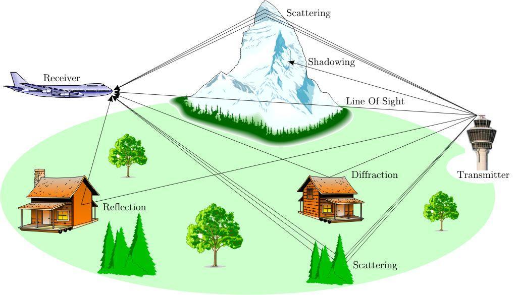
26 DEFINITIONS Multihop: Via the F2-layer signals can reach DX (distant stations) by doing several hops to the other side of the Earth. Skip Zone: The region between the furthest transmission points and the nearest point refracted waves can be received. Within this region, no signal can be received as there are no radio waves to receive. Skip Distance: The least distance between point of transmission and the point of reception Diffraction: High frequency radio waves can bend around the edge of an object such as a spot located out of sight from a transmitter (i.e. behind a hill), the remote radio is able to receive weak emissions because its signals are bending gradually by diffraction. This effect has practically no influence on HF since waves arrive usually to the receiver by many other means such as refraction or reflection in the upper atmosphere including sometimes ground waves if the transmitter is not too far ( km away).
27 PROPAGATION, HOPS, SKIPS ZONES Reflection: HF or long waves are reflected by the ground and upper atmosphere. As long wavelengths enter in contact with a surface, (80 meters and above) don't practically "see" small obstacles like cars, trees or buildings. These objects are proportionally too small and can't reflect its energy. The long waves pass across these materials without being reflected. VHF & UHF waves are very sensitive to small obstacles and depending of their thickness metal objects can be used as reflectors. Refraction: the bending of waves that occurs when they pass through a medium (air or the ionosphere) and produce a variation in the velocity (change of speed) of waves making them go further, or dropping sooner that expected. For example, a wave will refract and bend gradually given the appearance that the path is curved. Attenuation: When the distance doubles (remember inverse square relationship), or has obstacles placed between the emitter, receiver, and/or travelling around the earth, the signal becomes half as strong. Radio waves lose their energy as they are forced to bend to follow the earth curvature.
28 PROPAGATION, HOPS, SKIPS ZONES Signals are subject to fading and attenuation each time the radio wave is reflected or partially refracted at either the ground or ionosphere resulting in loss of energy. Signals my be stable and show little attenuation effect if the ionospheric absorption is very weak. 20m and 15m bands are the best for this type of traffic. In these bands you can work stations located over km s away. DX, telegraphic shorthand for "distance" or "distant & "X" refers to the unknown


29 Refraction is the change in direction of a wave due to a change in its speed Reflection is the change in direction of a wave front at an interface between two different media


30 Attenuation is the reduction in amplitude and intensity of a signal. It can also be understood to be the opposite of amplification is important in determining signal strength. Diffraction refers to various phenomena associated with wave propagation, such as the bending, spreading and interference of waves passing by an object or aperture that disrupts the wave
31

32 PROPAGATION, HOPS SKIPS ZONES
33 PROPAGATION, HOPS SKIPS ZONES CONT D The maximum distance along the earth s surface that is normally covered in one hop using the F2 region is 4000 Km (2500 miles). The maximum distance along the earth s surface that is normally covered in one hop using the E region is 2000 Km (1200 miles) If the distance to Europe from your location is approximately 5000 Km, Multihop propagation is most likely to be involved.
34 ABSORPTION AND FADING
35 ABSORPTION AND FADING Fading of signals is the effect at a receiver do to a disturbed propagation path. A local station will come in clearly, a distant station may rise and fall in strength or appear garbled. Fading may be caused by a variety of factors: a. A reduction of the ionospheric ionization level near sunset. b. Multi-path propagation: some of the signal is being reflected by one layer of the ionosphere and some by another layer. The signal gets to the receiver by two different routes The received signal may be enhanced or reduced by the wave interactions. In essence, radio signals' reaching the receiving antenna by two or more paths. Causes include atmospheric ducting (more on this latter), ionospheric reflection and refraction, and reflection from terrestrial objects, such as mountains and buildings. c. Increased absorption as the D layer builds up during the morning hours. d. Difference in path lengths caused by changing levels of ionization in the reflecting layer. e. E layer starts to disappear radio waves will pass through and be reflected by the F layer, thus causing the skip zone to fall beyond the receiving station. f. Selective fading: similar to Multi-path propagation, creates a hollow tone common on international shortwave AM reception. The signal arrives at the receiver by two different paths, and at least one of the paths is changing (lengthening or shortening). This typically happens in the early evening or early morning as the various layers in the ionosphere move, separate, and combine. The two paths can both be skywave or one can be ground wave.


36 ABSORPTION AND FADING Transmission signal Different paths Received signal
37 KNOWLEDGE CHECK
38 SOLAR ACTIVITY AND SUN SPOTS

39 SOLAR ACTIVITY AND SUN SPOTS The most critical factor affecting radio propagation is solar activity and the sunspot cycle. Sunspots are cooler regions where the temperature may drop to a frigid 4000K. Magnetic studies of the sun show that these are also regions of very high magnetic fields, up to 1000 times stronger than the regular magnetic field. Our Sun has sunspot cycle of about 22 years which reach both a minima and maxima (we refer to a 11 year low and high point or cycle). When the sunspots are at their maximum propagation is at its best. Ultraviolet radiation from the sun is the chief (though not the only) source of ionization in the upper atmosphere. During periods of low ultraviolet emission the ionization level of the ionosphere is low and radio signals with short wavelengths will pass through and be lost to space. During periods of high ultraviolet emission higher levels of ionization reflect higher frequencies and shorter wavelengths will propagate much longer distances.

: is a measure of the radio energy emitted from the sun. The solar flux value is considered to be one of the best ways of relating solar activity to propagation.")
40 SOLAR ACTIVITY AND SUN SPOTS CONT D Emission of larger amounts of ultraviolet radiation corresponds to increased surface activity on the sun. Length of a solar cycle can vary by one or two years in either direction from the 22 and 11 year average but it has remained near this value throughout geologic time. Solar maxima can also lead to highly variable propagation conditions due to periods of disturbance during solar magnetic disturbances (solar storms) which occur at this period. Solar Flux (Index): is a measure of the radio energy emitted from the sun. The solar flux value is considered to be one of the best ways of relating solar activity to propagation. When sun spot cycles hit their peaks the solar flux may have a value over 200. When the sun spot cycle is at its lowest point the solar flux values can be as low as 50 or 60. The higher the solar flux value the better propagation will be. Coronal Mass Ejections (CME)
41 SOLAR ACTIVITY AND SUN SPOTS CONT D Electromagnetic emissions and particle emissions hit the Earths ionosphere at various speeds with different energy levels. Effects of their impact varies accordingly but mainly affects sky waves. The particles emitted are accompanied by a tiny pulse of electromagnetic radiation. Electromagnetic and particle radiations can potentially modify the ionosphere and affect its properties. Electromagnetic emissions hit first the F-layer of the ionosphere increasing its ionization; atoms and molecules warm up and free one or more electrons. The higher the solar activity, the stronger the ionization of the F-layer. A strong ionization of the F-layer increases its reflecting power. Stronger ionization increase or raise the Maximum Usable Frequency or (MUF) (next section), regularly by 40 or 50 MHz in such occasions. Particle emissions are constituted of high-energy protons electrons forming solar cosmic rays when the sun releases huge amount of energy in Coronal Mass Ejections (CME). These particles of protons and heavy nuclei propagate into space, creating a shockwave. The pressure created by the particles clouds is huge and has a large effect on the ionosphere communications are interrupted

42 KNOWLEDGE CHECK
43 MF, HF CRITICAL FREQUENCIES
44 MF, HF CRITICAL FREQUENCIES Critical Frequency: the penetrating frequency and the highest frequency at which a radio wave, if directed vertically upward, will be refracted back to earth by an ionized layer. Radio waves at a frequency above the Critical Frequency will not be refracted/reflected. This will create a zone around the transmitter that will not receive signals known as the Skip Zone. The size of this zone will vary with the layer in use and the frequency in use. Maximum Usable Frequency (MUF): the highest frequency that will be reflected back to earth by the ionized layers. Above this frequency there is no reflection and thus no skip. MUF depends on the layer that is responsible for refraction/reflection and so contact between two stations relying on skip will depend on the amount of sunspot activity, the time of day, time of year, latitude of the two stations, and antenna transmission angle. The MUF is not significantly affected by transmitter power and receiver sensitivity Frequency of Optimum (Working)Transmission (FOT): is the highest effective (i.e. working) frequency that is predicted to be usable for a specified path and time for 90% of the days of the month. It is often abbreviated as FOT and normally just below the value of the MUF. The FOT is usually the most effective frequency for ionospheric reflection of radio waves between two specified points on Earth. Approximately 85 % of the MUF. The Lowest Usable high Frequency (LUF): the frequency in the HF band at which the received field intensity is sufficient to provide the required signal-to-noise ratio. The amount of energy absorbed by the lower regions of the ionosphere (D region, primarily) directly impacts the LUF Angle of Incidence: is a measure of deviation of something from "straight on", for example in the approach of a ray to a surface.
 /Optimal Working Frequency (OWF) Lower Absorption Frequency (ALF) / The lowest Usable")
45 MF, HF CRITICAL FREQUENCIES Maximum Useful Frequency (MUF) Above Critical Frequency Frequency of optimum transmission (FOT) /Optimal Working Frequency (OWF) Lower Absorption Frequency (ALF) / The lowest Usable frequency (LUF):


46 MF, HF CRITICAL FREQUENCIES incident angle and refraction transmission angle is higher frequency than the MUF. waves of the same frequency at several different transmission (and incident) angles Earth's Geomagnetic Fields: Activity in this field caused by interaction with charged particles from the sun can affect propagation.

47 KNOWLEDGE CHECK (More on beacons latter on!)

48 KNOWLEDGE CHECK CONT D
49 UHF, VHF, SPORADIC E, AURORAS, DUCTING
50 UHF, VHF, SPORADIC E, AURORAS, DUCTING Propagation above 30 MHz is normally not affected by conditions of the ionosphere. These radio waves pass through the ionosphere without refraction and escape to space. These frequencies are useful for Direct Wave Communication and for working Amateur satellites (ARISS / OSCAR) and moon-bounce (EME). The 6 metre band is an exception as under conditions of high sunspot activity it acquires some of the characteristics of the 10 metre band. The VHF band and above use direct waves and line of sight communications. The range of propagation can be slightly greater at times by a factor of 4/3 due to refraction effects in the Troposphere. This means under the right conditions, you can make contact with stations beyond the horizon. The effects diminish as the frequency increases. In certain favorable locations, enhanced tropospheric propagation may enable reception signals up to 800 miles or more. Other conditions which affect the propagation of VHF signals (and above) are: Sporadic-E: strongly ionized clouds can occur in the "E layer of the ionosphere and VHF signals will be refracted back to earth extending the range to a few thousand kilometers. Conditions occur primarily in the spring and late fall. Until recently 50 MHz (6 metre band) was considered to be the highest frequency useable for Sporadic-E operation. Increased 2 metre activity in the last decades show several DX records have been set using suspected Sporadic-E propagation and the highest frequency at which this propagation mode can be used must be considered to be as yet unknown.

51 UHF, VHF, SPORADIC E, AURORAS, DUCTING Temperature Inversion / Troposphere Ducting: Certain weather conditions produce a layer of air in the Troposphere that will be at a higher temperature than the layers of air above and below it. Such a layer will provide a "duct" creating a path through the warmer layer of air which has less signal loss than cooler layers above and below. These ducts occur over relatively long distances and at varying heights from almost ground level to several hundred meters above the earth's surface. This propagation takes place when hot days are followed by rapid cooling at night and affects propagation in the 50 MHz MHz range (6 meter, 2 meter, 1 1/4 meter and 70 centimeter bands). Signals can propagate hundreds of kilometers up to about 2,000 kilometers (1,300 mi).

52 UHF, VHF, SPORADIC E, AURORAS, Auroral Effects: Borealis or Northern Lights is strong ionization in the upper atmosphere and can be utilized to reflect signals. Requires a relatively high power transmitter and both stations point their antennas north toward the aurora. The preferred mode when working VHF aurora is CW although SSB can be used at 50 MHz. The received tone quality when using CW is very different than what you may be used to. Characteristic buzz, echo, very raspy and garbled tones can be expected. DUCTING The reason auroral signals sound different is they are being reflected by changing and rapidly-moving reflector (the ionised gases in the aurora). This results in multi-path reflections and the introduction of doppler shift into the signals.
53 UHF, VHF, SPORADIC E, AURORAS, DUCTING Hilly Terrain: mountainous area signals tend to be much shorter than those in open country. Signals are reflected off mountains and are also absorbed by them. If a signal passes over the top of a hill it may bend or refract back down the other side. The Concrete Jungle: Propagation in the city is similar to the effects found in mountainous terrain. A city will often be plagued by "mobile flutter", caused by multiple reflections of the signal off buildings. A move of 20 cm or so can make all the difference in the world. Working through a repeater can be complicated by the fact that you are using two different frequencies (some times called fence picketing). Equatorial E-skip: a regular daytime occurrence over the equatorial regions and is common in the temperate latitudes in late spring, early summer and, to a lesser degree, in early winter. For receiving stations located within +/ 10 degrees of the geomagnetic equator, equatorial E-skip can be expected on most days throughout the year, peaking around midday local time. Earth Moon Earth (EME) propagation (Moon Bounce): Radio amateurs have been experimenting with lunar communications by reflecting VHF and UHF signals off the moon between any two points that can observe the moon at a common time. Distance from earth means path losses are very high. The resulting signal level is often just above the noise.

54 KNOWLEDGE CHECK
55 SCATTER, HF, VHF,UHF

56 SCATTER, HF, VHF,UHF Scatter: A propagation type which occurs on a frequency very close to the maximum usable frequency. It produces a weak, and distorted signal when heard with in a skip zone since only parts of the signal is being recovered. Ionospheric scatter takes place as a result of anomalies in the propagating layer of the ionosphere that is being used for a particular path. Patches of intense ionisation, or local variations in height, can cause abnormal refraction to take place. Differences in the angles of incidence and refraction occur allowing over-the-horizon communication between stations as far as 500 miles (800 km) apart. Tropospheric Scatter (or Troposcatter): Signals via the troposphere travel farther than the line of sight. This is because of the height at which scattering takes place. The magnitude of the received signal depends on the number of turbulences causing scatter in the desired direction and the gain of the receiving antenna. The signal take-off angle (transmitting antenna's angle of radiation) determines the height of the scatter volume and the size of the scatter angle. The tropospheric region that contributes most strongly to tropospheric scatter propagation lies near the midpoint between the transmitting and receiving antennas and just above the radio horizon of the antennas. This effect sometimes allows reception of stations up to a hundred miles away.
57 SCATTER, HF, VHF,UHF Rain Scatter : A band of very heavy rain or (or rain and hail) can scatter or even reflect signals. Distances are typically around 160 km though up to 650 km (400 mi) is theoretically possible. Ice Pellet Scatter (called Sleet Scatter in the US) is similar to Rain Scatter but is caused by bands of Ice Pellets in the wintertime. Trans-Equatorial Scatter: It s possible for DX reception of television and radio stations between miles or km across the equator on frequencies as high as 432MHz. DX reception of lower frequencies in the 30 70MHz range is far more common. For this mode to work both transmitting and receiving stations should be almost the same distance from the equator. Aircraft Scatter (Tropospheric Reflection): Reflection off aircraft, (reflections off of flocks of birds are also possible).
.")

58 SCATTER, HF, VHF,UHF Chaff Scatter (strips of metal foil sent out by the military during training exercises). Chaff helps to confuse enemy radars but also helps to produce DX. Maximum distances for all reflection modes are again up to 800 km (500 mi). Meteor Scatter: as Meteors burn up entering the atmosphere it creates a quantity of ionized particles which reflect VHF radio waves. CW or SSB can make several rapid contacts during the brief openings that do occur. These openings may last from a few seconds to a minute or so. Lightning Scatter: there is little documentation on it but the theory is that lightning strikes produce ionized trails a mode that is very hard to distinguish and rarely reported.
59 KNOWLEDGE CHECK Scatter propagation would best be used by two stations within each other s skip zone on a certain or close to the MUF. If you receive a weak, distorted signal from a distance, and close to maximum usable frequency, scatter propagation is probably occurring. A wavering sound is characteristic of HF scatter signals Energy scattered into the skip zone through several radio-wave paths makes HF scatter Signals often sound distorted. HF scatter signals are usually weak because only a small part of the signal energy is scattered into the skip zone. Scatter propagation allows a signal to be detected at a distance to far for ground-wave propagation but to near for normal sky-wave propagation. Scatter propagation on the HF bands most often occurs when communicating on frequencies above and close to the maximum usable frequency (MUF) Side, Back, and Forward, Meteor, Ionospheric, and Tropospheric ARE all scatter modes. Inverted and Absorption are NOT scatter modes. In the MHz frequency range, meteor scatter is NOT the most effective for extended-range communications. Meteor scatter is the most effective on the 6 metre band.
60 Beacons There is a plethora of bacons around the world. These are used to determine propagation on the Amateur bands. The following slide deals with beacons on the 10m band

61 BEACONS - 10 METERS Operated by Amateur operators to determine propagation conditions. Ten meter beacons can be found between and MHZ. Beacons usually identify their location and power output by CW. Amateur operators can use this information to determine if favorable conditions exist between their location and the beacon s location. NCDXF/IARU International Beacon Network U1UN UNITED NATIONS VE8AT CANADA W6WX SAN JOSE, CA KH6WO HONOLULU, HI ZL6B NEW ZEALAND VK6RBP AUSTRALIA JA2IGY MT ASAMA, JAPAN RR9O NOVOSIBIRSK RUSSIA VR2R HONG KONG CHINA S7B SRI LANKA ZS6DN WINGATE PK S. AFRICA Z4B KENYA, AFRICA X6TU TEL AVIV OH2B KIRKKILA, FINLAND CS3B MADERIA IS LU4AA ARGENTINA OA4B PERU YV5B CARACAS, VEN
Chapter 6 Propagation
 Chapter 6 Propagation Al Penney VO1NO Objectives To become familiar with: Classification of waves wrt propagation; Factors that affect radio wave propagation; and Propagation characteristics of Amateur
4/29/2012. General Class Element 3 Course Presentation. Radio Wave Propagation. Radio Wave Propagation. Radio Wave Propagation.
 General Class Element 3 Course Presentation ti ELEMENT 3 SUB ELEMENTS General Licensing Class Subelement G3 3 Exam Questions, 3 Groups G1 Commission s Rules G2 Operating Procedures G3 G4 Amateur Radio
Lesson 12: Signal Propagation
 Lesson 12: Signal Propagation Preparation for Amateur Radio Technician Class Exam Topics HF Propagation Ground-wave Sky-wave Ionospheric regions VHF/UHF Propagation Line-of-sight Tropospheric Bending and
Chapter 7 HF Propagation. Ionosphere Solar Effects Scatter and NVIS
 Chapter 7 HF Propagation Ionosphere Solar Effects Scatter and NVIS Ionosphere and Layers Radio Waves Bent by the Ionosphere Daily variation of Ionosphere Layers Ionospheric Reflection Conduction by electrons
Reading 28 PROPAGATION THE IONOSPHERE
 Reading 28 Ron Bertrand VK2DQ http://www.radioelectronicschool.com PROPAGATION THE IONOSPHERE The ionosphere is a region of the upper atmosphere extending from a height of about 60 km to greater than 500
OBJECTIVES: PROPAGATION INTRO RADIO WAVES POLARIZATION LINE OF SIGHT, GROUND WAVE, SKY WAVE IONOSPHERE REGIONS PROPAGATION, HOPS, SKIPS ZONES THE
 WAVE PROPAGATION OBJECTIVES: PROPAGATION INTRO RADIO WAVES POLARIZATION LINE OF SIGHT, GROUND WAVE, SKY WAVE IONOSPHERE REGIONS PROPAGATION, HOPS, SKIPS ZONES THE IONOSPHERIC LAYERS ABSORPTION AND FADING
4/18/2012. Supplement T3. 3 Exam Questions, 3 Groups. Amateur Radio Technician Class
 Amateur Radio Technician Class Element 2 Course Presentation ti ELEMENT 2 SUB-ELEMENTS Technician Licensing Class Supplement T3 Radio Wave Characteristics 3 Exam Questions, 3 Groups T1 - FCC Rules, descriptions
Antennas and Propagation Chapters T4, G7, G8 Antenna Fundamentals, More Antenna Types, Feed lines and Measurements, Propagation
 Antennas and Propagation Chapters T4, G7, G8 Antenna Fundamentals, More Antenna Types, Feed lines and Measurements, Propagation =============================================================== Antenna Fundamentals
Topics in Propagation
 Topics in Propagation Extra Class Course Spring 2013 Andy Durbin k3wyc Propagation The magic that allows a signal to travel between the transmitting antenna and the receiving antenna. This course is limited
Technician License Course Chapter 4
 Technician License Course Chapter 4 Propagation, Basic Antennas, Feed lines & SWR K0NK 26 Jan 18 The Antenna System Antenna: Facilitates the sending of your signal to some distant station. Feed line: Connects
General Classs Chapter 7
 General Classs Chapter 7 Radio Wave Propagation Bob KA9BHD Eric K9VIC Learning Objectives Teach you enough to get all the propagation questions right during the VE Session Learn a few things from you about
RADIO WAVE PROPAGATION
 CHAPTER 2 RADIO WAVE PROPAGATION Radio direction finding (RDF) deals with the direction of arrival of radio waves. Therefore, it is necessary to understand the basic principles involved in the propagation
Maximum Usable Frequency
 Maximum Usable Frequency 15 Frequency (MHz) 10 5 0 Maximum Usable Frequency Usable Frequency Window Lowest Usable Frequency Solar Flare 6 12 18 24 Time (Hours) Radio Blackout Usable Frequency Window Ken
Amateur Radio License. Propagation and Antennas
 Amateur Radio License Propagation and Antennas Todays Topics Propagation Antennas Propagation Modes Ground wave Low HF and below, ground acts as waveguide Line-of-Sight (LOS) VHF and above, radio waves
Sw earth Dw Direct wave GRw Ground reflected wave Sw Surface wave
 WAVE PROPAGATION By Marcel H. De Canck, ON5AU Electromagnetic radio waves can propagate in three different ways between the transmitter and the receiver. 1- Ground waves 2- Troposphere waves 3- Sky waves
Polarization orientation of the electric field vector with respect to the earth s surface (ground).
.") Free space propagation of electromagnetic waves is often called radio-frequency (rf) propagation or simply radio propagation. The earth s atmosphere, as medium introduces losses and impairments to the
Free space propagation of electromagnetic waves is often called radio-frequency (rf) propagation or simply radio propagation. The earth s atmosphere, as medium introduces losses and impairments to the
AN INTRODUCTION TO VHF/ UHF PROPAGATION. Paul Wilton, M1CNK
 AN INTRODUCTION TO VHF/ UHF PROPAGATION Paul Wilton, M1CNK OVERVIEW Introduction Propagation Basics Propagation Modes Getting Started in 2m DX INTRODUCTION QRV on 2m SSB since Aug 1998, on 6m since Jan
Plasma in the ionosphere Ionization and Recombination
 Plasma in the ionosphere Ionization and Recombination Jamil Muhammad Supervisor: Professor kjell Rönnmark 1 Contents: 1. Introduction 3 1.1 History.3 1.2 What is the ionosphere?...4 2. Ionization and recombination.5
Broad Principles of Propagation 4C4
 Broad Principles of Propagation ledoyle@tcd.ie 4C4 Starting at the start All wireless systems use spectrum, radiowaves, electromagnetic waves to function It is the fundamental and basic ingredient of
1. Terrestrial propagation
 Rec. ITU-R P.844-1 1 RECOMMENDATION ITU-R P.844-1 * IONOSPHERIC FACTORS AFFECTING FREQUENCY SHARING IN THE VHF AND UHF BANDS (30 MHz-3 GHz) (Question ITU-R 218/3) (1992-1994) Rec. ITU-R PI.844-1 The ITU
Ionospheric Propagation
 Ionospheric Nick Massey VA7NRM 1 Electromagnetic Spectrum Radio Waves are a form of Electromagnetic Radiation Visible Light is also a form of Electromagnetic Radiation Radio Waves behave a lot like light
NVIS PROPAGATION THEORY AND PRACTICE
 NVIS PROPAGATION THEORY AND PRACTICE Introduction Near-Vertical Incident Skywave (NVIS) propagation is a mode of HF operation that utilizes a high angle reflection off the ionosphere to fill in the gap
Space Weather and Propagation JANUARY 14, 2017
 Space Weather and Propagation MARTIN BUEHRING -KB4MG ELEC T R ICAL ENGINEER, A M AT EUR EXTRA CLASS LICENSE HOLDER JANUARY 14, 2017 Why know about Space Weather? Our SUN has an enormous affect not only
right during the VE Session Have fun Bob, KA9BH Eric, K9VIC
 Radio Wave Propagation Teach you enough to get all right during the VE Session Learn a few things from you Have fun Finish everything on time (if the propagation questions about your experiences not a
High Frequency Propagation (and a little about NVIS)
") High Frequency Propagation (and a little about NVIS) Tom McDermott, N5EG August 18, 2010 September 2, 2010 Updated: February 7, 2013 The problem Radio waves, like light waves, travel in ~straight lines.
High Frequency Propagation (and a little about NVIS) Tom McDermott, N5EG August 18, 2010 September 2, 2010 Updated: February 7, 2013 The problem Radio waves, like light waves, travel in ~straight lines.
FCC Technician License Course
 FCC Technician License Course 2014-2018 FCC Element 2 Technician Class Question Pool Presented by: Tamiami Amateur Radio Club (TARC) WELCOME To the third of 4, 3-hour classes presented by TARC to prepare
RF Propagation. By Tim Kuhlman, PE KD7RUS
 RF Propagation By Tim Kuhlman, PE KD7RUS Purpose of this Seminar In this seminar we will attempt to answer the following questions: What is RF propagation? What are the different types of propagation?
Radio Frequency Propagation: A General Overview from LF to VHF.
 Radio Frequency Propagation: A General Overview from LF to VHF. Presented by: Mike Parkin GØJMI Slide 1 Introduction Mike Parkin: First licensed as G8NDJ in 1977. Became GØJMI in 1988. Interests in Radio
VHF Propagation Overview 5-Oct-2016
 VHF Propagation Overview 5-Oct-2016 G0RVM 1 VHF Propagation Where in the radio spectrum is VHF? 30MHz to 300MHz for radio amateurs its 50MHz, 70MHz & 144MHz or 6m, 4m & 2m Name some types of VHF propagation?
RADIO WAVES PROPAGATION
 RADIO WAVES PROPAGATION Definition Radio waves propagation is a term used to explain how radio waves behave when they are transmitted, or are propagated from one point on the Earth to another. Radio Waves
If maximum electron density in a layer is less than n', the wave will penetrate the layer
 UNIT-7 1. Briefly the describe the terms related to the sky wave propagation: virtual heights, critical frequency, maximum usable frequency, skip distance and fading? Ans: Sky wave propagation: It is also
Global Maps with Contoured Ionosphere Properties Some F-Layer Anomalies Revealed By Marcel H. De Canck, ON5AU. E Layer Critical Frequencies Maps
 Global Maps with Contoured Ionosphere Properties Some F-Layer Anomalies Revealed By Marcel H. De Canck, ON5AU In this column, I shall handle some possibilities given by PROPLAB-PRO to have information
Terry G. Glagowski W1TR / AFA1DI
 The Ionogram and Radio Propagation By Terry G. Glagowski / W1TR / AFA1DI - 9/29/2017 9:46 AM Excerpts from a presentation by Tom Carrigan / NE1R / AFA1ID by Terry G. Glagowski W1TR / AFA1DI Knowledge of
Introduction to HF Propagation. Rick Fletcher, W7YP FVARC November 20, 2018
 Introduction to HF Propagation Rick Fletcher, W7YP FVARC November 20, 2018 Topics The HF Bands How HF propagation works Overview by HF band Sources of solar and propagation information Working HF during
RF Propagation. By Tim Kuhlman, PE KD7RUS
 RF Propagation By Tim Kuhlman, PE KD7RUS Purpose of this Seminar In this seminar we will attempt to answer the following questions: What is RF propagation? What are the different types of propagation?
Propagation Tool.
 Propagation Propagation Tool http://www.hamqsl.com/solar.html The Ionosphere is made up of several layers at varying heights above the ground: The lowest level is the D Layer (37 to 56 miles), which
Chapter 15: Radio-Wave Propagation
 Chapter 15: Radio-Wave Propagation MULTIPLE CHOICE 1. Radio waves were first predicted mathematically by: a. Armstrong c. Maxwell b. Hertz d. Marconi 2. Radio waves were first demonstrated experimentally
UNIT V PROPAGATION The three basic types of propagation: Sky Wave Propagation: Space Wave Propagation: Ground Wave Propagation: Propagation of Waves
 UNIT V PROPAGATION The three basic types of propagation: Ground wave, space wave and sky wave propagation. Sky Wave Propagation: Structure of the ionosphere Effective dielectric constant of ionized region
3 Methods of radiocommunication
 + + & & * * ) ) From the ITU Emergency Telecommunications handbook; prepared for the 54 th JOTA 2011. 3 Methods of radiocommunication 3.1 Frequencies Radio frequencies should be selected according to propagation
Radiation and Particles from the. Sun
 2017 Radiation and Particles from the Photons Sun Photons (300000km/s ~ 8m 20s) radio waves, infra red, visible light, ultra violet, x-ray, x galactic waves, Solar Flux (30000km/s ~ 8m 20s) The 10.7 cm
Chapter 1: Telecommunication Fundamentals
 Chapter 1: Telecommunication Fundamentals Block Diagram of a communication system Noise n(t) m(t) Information (base-band signal) Signal Processing Carrier Circuits s(t) Transmission Medium r(t) Signal
# DEFINITIONS TERMS. 2) Electrical energy that has escaped into free space. Electromagnetic wave
 Electrical energy that has escaped into free space. Electromagnetic wave") CHAPTER 14 ELECTROMAGNETIC WAVE PROPAGATION # DEFINITIONS TERMS 1) Propagation of electromagnetic waves often called radio-frequency (RF) propagation or simply radio propagation. Free-space 2) Electrical
CHAPTER 14 ELECTROMAGNETIC WAVE PROPAGATION # DEFINITIONS TERMS 1) Propagation of electromagnetic waves often called radio-frequency (RF) propagation or simply radio propagation. Free-space 2) Electrical
Space Weather and the Ionosphere
 Dynamic Positioning Conference October 17-18, 2000 Sensors Space Weather and the Ionosphere Grant Marshall Trimble Navigation, Inc. Note: Use the Page Down key to view this presentation correctly Space
14. COMMUNICATION SYSTEM
 14. COMMUNICATION SYSTEM SYNOPSIS : INTRODUCTION 1. The exchange of information between a sender and receiver is called communication. 2. The arrangement of devices to transfere the information is called
Data and Computer Communications Chapter 4 Transmission Media
 Data and Computer Communications Chapter 4 Transmission Media Ninth Edition by William Stallings Data and Computer Communications, Ninth Edition by William Stallings, (c) Pearson Education - Prentice Hall,
Ionospheric Propagation
 Ionospheric Propagation Page 1 Ionospheric Propagation The ionosphere exists between about 90 and 1000 km above the earth s surface. Radiation from the sun ionizes atoms and molecules here, liberating
Regional and Long Distance Skywave Communications
 Regional and Long Distance Skywave Communications F LAYER SKYWAVE ELEVATION ANGLE STATION - A STATION - B Ken Larson KJ6RZ October 2010 1 Page Title 3 1.0 Introduction 3 2.0 The Earth s Ionosphere 6 3.0
The Basics of VHF and UHF Signal Propagation
 The Basics of VHF and UHF Signal Propagation The Electromagnetic Spectrum - The electromagnetic spectrum is a continuum of all electromagnetic waves arranged according to frequency and wavelength. Electromagnetic
UNIT Derive the fundamental equation for free space propagation?
 UNIT 8 1. Derive the fundamental equation for free space propagation? Fundamental Equation for Free Space Propagation Consider the transmitter power (P t ) radiated uniformly in all the directions (isotropic),
Electronics Technician
 NAVEDTRA 12417 Naval Education and October 1995 Training Manual Training Command 0502-LP-480-2900 (TRAMAN) Electronics Technician Volume 7 Antennas and Wave Propagation DISTRIBUTION STATEMENT A: Approved
Electromagnetic Waves
 Electromagnetic Waves What is an Electromagnetic Wave? An EM Wave is a disturbance that transfers energy through a field. A field is a area around an object where the object can apply a force on another
SCARS Technician / General License Course Week 4
 SCARS Technician / General License Course Week 4 Radio Wave Propagation: Getting from Point A to Point B Radio waves propagatein many ways depending on Frequency of the wave Characteristics of the environment
Radar Reprinted from "Waves in Motion", McGourty and Rideout, RET 2005
 Radar Reprinted from "Waves in Motion", McGourty and Rideout, RET 2005 What is Radar? RADAR (Radio Detection And Ranging) is a way to detect and study far off targets by transmitting a radio pulse in the
Electronics Technician
 NONRESIDENT TRAINING COURSE Electronics Technician Volume 7 Antennas and Wave Propagation NAVEDTRA 14092 Notice: NETPDTC is no longer responsible for the content accuracy of the NRTCs. For content issues,
1. What are the applications of loop antenna? (May2011) 2. Define Pattern Multiplication (May2011)
 2. Define Pattern Multiplication (May2011)") UNIT-II WIRE ANTENNAS AND ANTENNA ARRAYS 1. What are the applications of loop antenna? (May2011) 2. Define Pattern Multiplication (May2011) 3. A uniform linear array contains 50 isotropic radiation with
UNIT-II WIRE ANTENNAS AND ANTENNA ARRAYS 1. What are the applications of loop antenna? (May2011) 2. Define Pattern Multiplication (May2011) 3. A uniform linear array contains 50 isotropic radiation with
PoS(2nd MCCT -SKADS)003
003") The Earth's ionosphere: structure and composition. Dispersive effects, absorption and emission in EM wave propagation 1 Observatorio Astronómico Nacional Calle Alfonso XII, 3; E-28014 Madrid, Spain E-mail:
The Earth's ionosphere: structure and composition. Dispersive effects, absorption and emission in EM wave propagation 1 Observatorio Astronómico Nacional Calle Alfonso XII, 3; E-28014 Madrid, Spain E-mail:
VHF/UHF Beyond FM Bob Witte KØNR Page 1
 VHF/UHF Beyond FM Technical Coordinator Colorado Section Page 1 Objective The objective of this presentation is to provide an introduction to operating on VHF/UHF, going beyond the usual FM / Repeater
Antennas & Propagation. CSG 250 Fall 2007 Rajmohan Rajaraman
 Antennas & Propagation CSG 250 Fall 2007 Rajmohan Rajaraman Introduction An antenna is an electrical conductor or system of conductors o Transmission - radiates electromagnetic energy into space o Reception
(A) 2f (B) 2 f (C) f ( D) 2 (E) 2
 2f (B) 2 f (C) f ( D) 2 (E) 2") 1. A small vibrating object S moves across the surface of a ripple tank producing the wave fronts shown above. The wave fronts move with speed v. The object is traveling in what direction and with what
1. A small vibrating object S moves across the surface of a ripple tank producing the wave fronts shown above. The wave fronts move with speed v. The object is traveling in what direction and with what
Radio Propagation - VHF and higher
 Radio Propagation - VHF and higher (Without the Mathematics) Presented by Dr John Worsnop G4BAO RSGB Propagation Studies Committee RadCom GHz bands Columnist With a little help from http://www.mike-willis.com/tutorial/propagation.html
Unguided Media and Matched Filter After this lecture, you will be able to Example?
 Unguided Media and Matched Filter After this lecture, you will be able to describe the physical and transmission characteristics of various unguided media Example? B.1 Unguided media Guided to unguided
Definitions of Technical Terms
 Definitions of Technical Terms Terms Ammeter Amperes, Amps Band Capacitor Carrier Squelch Diode Dipole Definitions How is an ammeter usually connected = In series with the circuit What instrument is used
VI. Signal Propagation Effects. Image courtesy of
 VI. Signal Propagation Effects Image courtesy of www.tpub.com 56 VI. Signal Propagation Effects Name Date Class At Home Assignment Tune to the most remote AM station you can find. You should attempt to
Antennas and Propagation. Prelude to Chapter 4 Propagation
 Antennas and Propagation Prelude to Chapter 4 Propagation Introduction An antenna is an electrical conductor or system of conductors for: Transmission - radiates electromagnetic energy into space (involves
Channel Modeling and Characteristics
 Channel Modeling and Characteristics Dr. Farid Farahmand Updated:10/15/13, 10/20/14 Line-of-Sight Transmission (LOS) Impairments The received signal is different from the transmitted signal due to transmission
RECOMMENDATION ITU-R P Prediction of sky-wave field strength at frequencies between about 150 and khz
 Rec. ITU-R P.1147-2 1 RECOMMENDATION ITU-R P.1147-2 Prediction of sky-wave field strength at frequencies between about 150 and 1 700 khz (Question ITU-R 225/3) (1995-1999-2003) The ITU Radiocommunication
A first study into the propagation of 5 MHz (60 m) signals using the South African ionosonde network
 signals using the South African ionosonde network") A first study into the propagation of 5 MHz (60 m) signals using the South African ionosonde network Hannes Coetzee, B. Eng. (Electronics), M. Sc. (Physics), ZS6BZP The SARL has purchased two 5 MHz test
A first study into the propagation of 5 MHz (60 m) signals using the South African ionosonde network Hannes Coetzee, B. Eng. (Electronics), M. Sc. (Physics), ZS6BZP The SARL has purchased two 5 MHz test
Electronics Technician
 NONRESIDENT TRAINING COURSE Electronics Technician Volume 7 Antennas and Wave Propagation NAVEDTRA 14092 DISTRIBUTION STATEMENT A: Approved for public release; distribution is unlimited. Sailor s Creed
Chapter 13: Wave Propagation. EET-223: RF Communication Circuits Walter Lara
 Chapter 13: Wave Propagation EET-223: RF Communication Circuits Walter Lara Electrical to Electromagnetic Conversion Since the atmosphere is not a conductor of electrons (instead a good insulator), electrical
Wireless Transmission Rab Nawaz Jadoon
 Wireless Transmission Rab Nawaz Jadoon DCS Assistant Professor COMSATS IIT, Abbottabad Pakistan COMSATS Institute of Information Technology Mobile Communication Frequency Spectrum Note: The figure shows
Chapter 16 Light Waves and Color
 Chapter 16 Light Waves and Color Lecture PowerPoint Copyright The McGraw-Hill Companies, Inc. Permission required for reproduction or display. What causes color? What causes reflection? What causes color?
Chapter 1 Introduction
 Wireless Information Transmission System Lab. Chapter 1 Introduction National Sun Yat-sen University Table of Contents Elements of a Digital Communication System Communication Channels and Their Wire-line
Dartmouth College SuperDARN Radars
 Dartmouth College SuperDARN Radars Under the guidance of Thayer School professor Simon Shepherd, a pair of backscatter radars were constructed in the desert of central Oregon over the Summer and Fall of
Technical and operational characteristics of land mobile MF/HF systems
 Recommendation ITU-R M.1795 (03/2007) Technical and operational characteristics of land mobile MF/HF systems M Series Mobile, radiodetermination, amateur and related satellite services ii Rec. ITU-R M.1795
Introduction To The Ionosphere
 Introduction To The Ionosphere John Bosco Habarulema Radar School 12 13 September 2015, SANSA, What is a radar? This being a radar school... RAdio Detection And Ranging To determine the range, R, R=Ct/2,
Class Overview. Antenna Fundamentals Repeaters Duplex and Simplex Nets and Frequencies Cool Radio Functions Review
 Class Overview Antenna Fundamentals Repeaters Duplex and Simplex Nets and Frequencies Cool Radio Functions Review Antennas Antennas An antenna is a device used for converting electrical currents into electromagnetic
Plasma in the Ionosphere Ionization and Recombination
 Plasma in the Ionosphere Ionization and Recombination Agabi E Oshiorenoya July, 2004 Space Physics 5P Umeå Universitet Department of Physics Umeå, Sweden Contents 1 Introduction 6 2 Ionization and Recombination
Unguided Transmission Media
 CS311 Data Communication Unguided Transmission Media by Dr. Manas Khatua Assistant Professor Dept. of CSE IIT Jodhpur E-mail: manaskhatua@iitj.ac.in Web: http://home.iitj.ac.in/~manaskhatua http://manaskhatua.github.io/
Chapter 4. Propagation, Antennas and Feed Lines. Propagation Black magic topic #1. How do radio waves get from point A to point B?
 Chapter 4 Propagation, Antennas and Feed Lines Propagation Black magic topic #1. How do radio waves get from point A to point B? 1 Radio Wave Propagation Normally radio waves travel in a straight line,
Get Discount Coupons for your Coaching institute and FREE Study Material at COMMUNICATION SYSTEMS
 COMMUNICATION SYSTEMS 1. BASICS OF COMMUNICATION 2. AMPLITUDE MODULATION Get Discount Coupons for your Coaching institute and FREE Study Material at www.pickmycoaching.com 1 BASICS OF COMMUNICATION 1.
WEATHER - RELATED INTERFERENCE
 WEATHER - RELATED INTERFERENCE Many people are familiar with the interference to TV and FM Radio reception that can occur during abnormal weather conditions. Doesn't it always seem to happen in the middle
ATS 351 Lecture 9 Radar
 ATS 351 Lecture 9 Radar Radio Waves Electromagnetic Waves Consist of an electric field and a magnetic field Polarization: describes the orientation of the electric field. 1 Remote Sensing Passive vs Active
Study of small scale plasma irregularities. Đorđe Stevanović
 Study of small scale plasma irregularities in the ionosphere Đorđe Stevanović Overview 1. Global Navigation Satellite Systems 2. Space weather 3. Ionosphere and its effects 4. Case study a. Instruments
Radio Communication. Presentation created by: András Balogh
 Radio Communication Presentation created by: András Balogh AM and FM The goal is to transmit a modulating signal S(t) via a wave sin(ωt). In case of AM, the product of the modulation is f(t)=(a+s(t))*sin(ωt);
Unit 1.5 Waves. The number waves per second. 1 Hz is 1waves per second. If there are 40 waves in 10 seconds then the frequency is 4 Hz.
 Unit 1.5 Waves Basic information Transverse: The oscillations of the particles are at right angles (90 ) to the direction of travel (propagation) of the wave. Examples: All electromagnetic waves (Light,
DYNAMIC POSITIONING CONFERENCE October 17 18, 2000 SENSORS. Space Weather and the Ionosphere. Grant Marshall Trimble Navigation Inc.
 DYNAMIC POSIIONING CONFERENCE October 17 18, 2000 SENSORS Space Weather and the Ionosphere Grant Marshall rimble Navigation Inc. Images shown here are part of an animated presentation and may not appear
ELECTROMAGNETIC WAVES AND THE EM SPECTRUM MR. BANKS 8 TH GRADE SCIENCE
 ELECTROMAGNETIC WAVES AND THE EM SPECTRUM MR. BANKS 8 TH GRADE SCIENCE ELECTROMAGNETIC WAVES Do not need matter to transfer energy. Made by vibrating electric charges. When an electric charge vibrates,
ABC Math Student Copy
 Page 1 of 17 Physics Week 9(Sem. 2) Name Chapter Summary Waves and Sound Cont d 2 Principle of Linear Superposition Sound is a pressure wave. Often two or more sound waves are present at the same place
Antennas and Propagation. Chapter 5
 Antennas and Propagation Chapter 5 Introduction An antenna is an electrical conductor or system of conductors Transmission - radiates electromagnetic energy into space Reception - collects electromagnetic
Antennas and Propagation
 Mobile Networks Module D-1 Antennas and Propagation 1. Introduction 2. Propagation modes 3. Line-of-sight transmission 4. Fading Slides adapted from Stallings, Wireless Communications & Networks, Second
THE IONOSPHERE AND RADIO PROPAGATION
 INTERNATIONAL JOURNAL OF ELECTRONICS AND COMMUNICATION ENGINEERING & TECHNOLOGY (IJECET) International Journal of Electronics and Communication Engineering & Technology (IJECET), ISSN 0976 ISSN 0976 6464(Print)
Antennas and Propagation. Chapter 5
 Antennas and Propagation Chapter 5 Introduction An antenna is an electrical conductor or system of conductors Transmission - radiates electromagnetic energy into space Reception - collects electromagnetic
Session2 Antennas and Propagation
 Wireless Communication Presented by Dr. Mahmoud Daneshvar Session2 Antennas and Propagation 1. Introduction Types of Anttenas Free space Propagation 2. Propagation modes 3. Transmission Problems 4. Fading
Introductory Physics, High School Learning Standards for a Full First-Year Course
 Introductory Physics, High School Learning Standards for a Full First-Year Course I. C ONTENT S TANDARDS 4.1 Describe the measurable properties of waves (velocity, frequency, wavelength, amplitude, period)
A Review of WICEN HF Communications Capability
 A Review of WICEN HF Communications Capability Abstract During a recent event, some problems were experienced with the traditional lower HF band communications often used for WICEN events. This paper describes
Electromagnetic (Light) Waves Electromagnetic Waves
 Waves Electromagnetic Waves") Physics R Date: Review Questions 1. An ocean wave traveling at 3 m/s has a wavelength of 1.6 meters. a. What is the frequency of the wave? b. What is the period of the wave? Electromagnetic (Light) Waves
Physics R Date: Review Questions 1. An ocean wave traveling at 3 m/s has a wavelength of 1.6 meters. a. What is the frequency of the wave? b. What is the period of the wave? Electromagnetic (Light) Waves
GraspIT Questions AQA GCSE Physics Waves
 A Waves in air, fluids and solids 1. The diagrams below show two types of wave produced on a slinky spring. A B a. Which one is a transverse wave? (1) Wave B b. What is the name of the other type of wave?
Outlines. Attenuation due to Atmospheric Gases Rain attenuation Depolarization Scintillations Effect. Introduction
 PROPAGATION EFFECTS Outlines 2 Introduction Attenuation due to Atmospheric Gases Rain attenuation Depolarization Scintillations Effect 27-Nov-16 Networks and Communication Department Loss statistics encountered
DDPP 2163 Propagation Systems. Satellite Communication
 DDPP 2163 Propagation Systems Satellite Communication 1 Satellite Two far apart stations can use a satellite as a relay station for their communication It is possible because the earth is a sphere. Radio
RADIOWAVE PROPAGATION
 RADIOWAVE PROPAGATION Physics and Applications CURT A. LEVIS JOEL T. JOHNSON FERNANDO L. TEIXEIRA The cover illustration is part of a figure from R.C. Kirby, "Introduction," Lecture 1 in NBS Course in