Radio Technology Somfy. Pocket Programming Guide
|
|
|
- Laureen Gregory
- 6 years ago
- Views:
Transcription


1 Radio Technology Somfy Pocket Programming Guide
2 Table of Contents P. 1 How Does RTS Work? P. 2 Identify RTS Control Options Transmitters P. 4 DecoFlex Wireless Wall Switch P. 5 DecoFlex Table Top Accessory P. 6 Telis Hand-Held Remote P. 7 Telis Soliris Hand-Held Remote P. 8 Telis Modulis Hand-Held Remote P. 9 Telis 16 Channel Hand-Held Remote P. 10 Telis 1 Chronis RTS Hand-Held Remote Repeater P. 11 RTS Repeater Receivers P. 12 Outdoor Lighting Receiver P. 13 Outdoor Universal Receiver Interfaces P. 14 Universal RTS Interface (URTSI) P. 15 mylink Sensors P. 16 Sunis Indoor WireFree Sensor P. 16 Thermo Sunis Indoor WireFree Sensor P. 17 Eolis 3D WireFree Wind Sensor P. 18 Ondeis WireFree RTS Rain & Sun Sensor Understanding Control Options P. 20/21 Individual Control P. 22/23 Group Control P. 24/25 Individual & Group Control P. 26 Product Application & Motor Compatibility Chart
3 RTS Motor Range P. 28 CL32 Cord Lift WireFree P. 28 CT32 Cord Lift WireFree P. 28 Tilt WireFree P. 28 LT30 Roll Up WireFree P. 29 ST30 Sonesse 30 P. 29 ST40 Sonesse 40 P. 29 Altus 40 P. 30 ST50 Sonesse 50 P. 30 Altus 50 P. 30 LT50 RTS CMO P. 31 Sunea RTS CMO P. 31 Oximo RTS P. 31 Altus 60 P. 32 Glydea 35 P. 32 Glydea 60 Quick Programming Guides P CL32 Cord Lift WireFree CT32 Cord Lift WireFree LT30 Roll Up WireFree ST30 Sonesse 30 ST40 Sonesse 40 Altus 40 ST50 Sonesse 50 Altus 50 Altus 60 P Tilt WireFree P LT RTS CMO P Sunea RTS CMO P Oximo RTS P Glydea P. 61 Outdoor Lighting Receiver RTS P. 62 Outdoor Universal Receiver RTS P. 63 RTS Repeater P. 63 Universal RTS Interface (URTSI) P mylink P Sunis Indoor WireFree Sensor P Thermo Sunis Indoor WireFree Sensor P Eolis 3D WireFree Wind Sensor P Ondeis WireFree RTS Rain & Sun Sensor P Telis 16 RTS P Telis 1 Chronis RTS P. 94 Troubleshooting


4 Home Motion by Somfy We ve developed a brand expression that emphasizes the centerpiece of consumers lives, the home. It also represents Somfy s mission, bringing homes to life by creating movement for all openings and allowing consumers to enjoy life s daily pleasures for a better quality of life.
 is omni-directional. And just like a garage door opener, the radio waves travel through walls.")
5 How Does It Work? Simply press a button on a remote control or wall switch and window coverings move with ease. There is no need to point or aim the transmitter at the covering because Radio Technology Somfy (RTS) is omni-directional. And just like a garage door opener, the radio waves travel through walls. Available with hand-held remotes, wireless wall switches, table top controls, timers and a convenient app. No need to aim the control at the motorized window covering, the radio signal travels through walls similar to a garage door opener Offers a range of 65 ft. for easy operation No extra wires are needed Provides the ability to control all motorized window coverings individually and/or as a group with one control Flexibility to change user preferences with simplified programming Available in single and multi-channel versions Over 10 million installations worldwide Secure operation with a rolling code reducing interference with other radio products Offers simplified integration with home automation systems 1
6 Identify RTS Control Options Transmitters Hand-Held Remotes Users can control motorized window coverings by pressing a button or rolling a scroll wheel on a variety of hand-held RTS remotes. Wireless Wall Switches Users can easily control their motorized window coverings when entering or exiting a room with DecoFlex WireFree RTS Wall Switches. Table Top Remotes Users can control their motorized window coverings with the versatile DecoFlex WireFree RTS Table Top Accessory remote. Receivers Users can adjust window coverings powered by standard motors, as well as operate incandescent and halogen lights and other outdoor devices by using a particular receiver. Interfaces Users can convert Infrared, RS232, RS485 and WiFi protocol into RTS, allowing for 3rd party control of motorized window coverings. Repeater Users can extend the range of motorized window covering control. Sensors Users can set sensors to automatically adjust motorized window coverings in accordance to the amount of sunlight received, temperature recorded, as well as the speed and direction of wind. 2
7 Control Options 3

8 DecoFlex WireFree RTS Wall Switch Features Programming Button (recessed) 5 Channel Button DecoFlex WireFree RTS Wall Switch shown in White Finish Also available in multiple finishes and various channel button versions: Ivory Black Almond Custom engraved buttons available. 4


 UP AND DOWN Command Buttons DecoFlex WireFree RTS Table Top Accessory Control shown in")
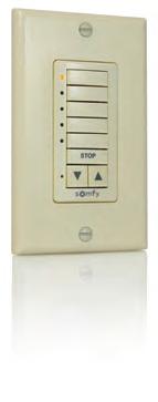
9 DecoFlex WireFree RTS Table Top Accessory Features Easily personalize your control with custom engraved button names. LED for each channel. Available in 1, 2, 3, 4 and 5 channel versions. Channel Buttons can be labeled for easy organization. (custom engraving also available). STOP button stops the window covering when it s in motion. When the window covering is stationary, the STOP button brings it to the programmed favorite position. Programming Button (recessed) UP AND DOWN Command Buttons DecoFlex WireFree RTS Table Top Accessory Control shown in Silver Finish Ergonomically designed for comfortable hand-held use. Features rubber non-slip feet. Side view Also available in black & white finishes: 5

10 Telis RTS Hand-Held Remote Features UP Button The my button acts as a stop button when the window covering is in motion. When the window covering is stationary, the my button brings it to the programmed favorite position. DOWN Button Channel LED All 4 lights will illuminate when fifth channel is activated. Channel Selector Button Channel 1 Channel 2 Channel 3 Channel 4 Channel 5 Telis 4 RTS Hand-Held Remote shown in Pure finish Telis 1 RTS also available Also available in multiple finishes: Programming Button (recessed) Silver Lounge Patio Back view of Remote 6
11 Telis Soliris RTS Hand-Held Remote Features UP Button The my button acts as a stop button when the awning is in motion. When the window covering is stationary, the my button brings it to the programmed favorite position. DOWN Button When left LED is lit the window covering will only react to wind control. When right LED is lit the window covering will react to both sun and wind control. Channel Selector Button Telis Soliris RTS Hand-Held Remote shown in Pure finish Telis 4 Soliris RTS also available Patio option available also: Programming Button (recessed) Back view of Remote 7

12 Telis RTS Modulis Hand-Held Remote Features Open/Close buttons Scroll wheel for incremental tilt control of horizontal blinds and sheer horizontal products. my button for a favorite blind position LED identifies active channel Channel Selector Button Channel 1 Channel 2 Channel 3 Channel 4 Channel 5 Telis 4 Modulis RTS Hand-Held Remote Telis 1 Modulis RTS also available Programming Button (recessed) Back view of Remote 8
 assigned to that channel.")
13 Telis 16 Channel RTS Hand-Held Remote Features Signal Indicator On-Screen LCD Display Channel Number 16 channels can be used to control 16 individual motorized applications or 16 groups of motorized applications. Product Icon A choice of 3 icons is available to visually represent the product(s) assigned to that channel. Product Name (up to 8 characters: 7 Letters + 1 Number) Selection Button Channel Navigation Buttons UP Button Favorite position my Button The my button acts as a stop button when the window covering is in motion. When the window covering is stationary, the my button brings it to the programmed favorite position. DOWN Button Telis 16 Channel RTS Hand-Held Remote shown in Pure finish NOTE: The Telis 16 channel remote features an LCD screen that numerically displays what channel is selected. Programming Button (recessed) Also available in Silver finish Back view of Remote 9
 On-Screen LCD Display Current Time Programmed Days -2 possible schedules: Daily schedule - same cycle everyday.")
14 Telis Chronis 1 RTS Hand-Held Remote Features Vacation Mode (Only displayed when function is activated. Varies scheduled time to simulate a lived in look.) On-Screen LCD Display Current Time Programmed Days -2 possible schedules: Daily schedule - same cycle everyday. Weekday & weekend schedule - 2 UP & DOWN times (1 for weekdays & 1 for weekends) Low Battery Indicator (notifies when batteries need replacing) Time Slots Confirm Selection Button Channel Navigation Buttons UP Button Favorite position my Button The my button acts as a stop button when the window covering is in motion. When the window covering is stationary, the my button brings it to the programmed favorite position. DOWN Button Telis Chronis 1 RTS Hand-Held Remote # shown in Pure finish Programming Button (recessed) Also available in Silver finish # Back view of Remote 10


15 RTS Repeater Features Antenna The RTS Repeater receives the signal from a Telis RTS remote or DecoFlex WireFree RTS wall switch or similar device and re-transmits the signal to an RTS compatible motor or receiver to extend the RTS range. Indicator Light Simply plugs into any 120V AC electrical outlet. No programming required. Should be placed approximately halfway between the transmitting device such as a Telis hand-held remote and the receiving device, the motor. Solves the challenge of transmitting the signal in particularly large rooms or areas. Range: 60 ft. 11

16 Outdoor Lighting Receiver RTS Features *For programming instructions please go to P. 60 Control patio or deck lights with the same remote used for the awning. Controls incandescent, halogen lights or any outdoor device up to 500W. Fully compatible with the Telis RTS range of transmitters and the DecoFlex WireFree RTS wall switches. Weatherproof cover with watertight strain-relief fittings for wires SEQUENTIAL CONTROL BUTTON GROUND PROGRAMMING BUTTON PROGRAMMING LED 500W Max Lighting Output NEUT HOT NEUT HOT LAMP 500 WATTS MAX. GROUND NEUTRAL HOT 12

17 R Outdoor Universal RTS Receiver Features *For programming instructions please go to P. 59 Provides RTS capability to Somfy s standard motors. Can be used as a stand-alone RTS control or with RTS sensors. Two user-defined intermediate positions can be programmed. Weatherproof cover with watertight strain-relief fittings for wires SEQUENTIAL CONTROL BUTTON GROUND PROGRAMMING BUTTON UP DOWN PROGRAMMING LED MOTOR MTR COM NEUT HOT NEUT HOT GROUND NEUTRAL HOT 13
 IR Sensor Port RS485 Expansion")
 to")


18 Universal RTS Interface (URTSI) Features Antenna 9 Volt DC (power supply included) IR Sensor Port RS485 Expansion RS232 or RS485 Input Allows user to convert infrared, RS232 and RS485 protocol into Radio Technology Somfy (RTS) to allow for third party control. Offers 16 channels. Compatible with full range of RTS motors. With its compact and sleek design, the URSTI can be housed in a discrete location. UP STOP DOWN Program Button Channel Selector RTS Transmission LED 14

19 Somfy mylink TM Features TM The Somfy mylink offers convenient control of any Radio Technology Somfy RTS motorized application with a smartphone or tablet. It consists of a simple plug-in device and free app that transforms the experience that users have with there motorized applications. LED Indicator States - 1. Solid Red: setup mode (out of the box) a. Re-engage by pressing programming button on the side 2. Solid Green: connected to LAN 3. Slow Blinking Green: searching for network 4. Quick Red Flash: sending RTS command 5. Solid Amber: failsafe mode LED Indicator Light App Status Indicator - White O: mobile device can connect to the mylink(s) and commands are being sent over the local wifi network. White O with Sight: mobile device can connect to the mylink(s) and commands are being sent over the internet. White O with!: the mobile device cannot connect to a mylink/mylinks. 15


20 Sunis & Thermo Sunis Indoor WireFree RTS Sensors Sunis Features - Front view with cover removed LED Indicator ON/OFF Selector Switch Control Setting Panel Programming Button window sill mount Mode Button Sun Sensitivity Threshold Adjustment window mount The Sunis Indoor Sensor can be programmed to automatically adjust window coverings in accordance to sunlight threshold settings. Thermo Sunis Features - Temperature LED Indicator ON/OFF Selector Switch Sunlight LED Indicator Front view with cover removed Sun & Temperature Sensitivity Threshold Adjustment Mode Button Control Setting Panel Front view with cover removed Programming Button Function Selection Switch The Thermo Sunis Sensor can be programmed to automatically adjust window coverings in accordance to sunlight and/or room temperature threshold settings. Front view with cover installed Suction cup for mounting on window sill or window Back View Light sensing eye 16


21 Eolis 3D WireFree RTS Wind Sensor Features Installed discreetly on the end of the front bar. Easy wireless installation. Automatically retracts the awning with the detection of wind generated movements. Easy to program. Maintenance free, long life batteries. Programming Button Sensitivity Adjustment Button Mounting Plate Also available in multiple finishes: Ivory Black 17

 Awning Sun (requires Telis Soliris Transmitter) Awning Rain &")


22 Ondeis WireFree RTS Rain and Sun Sensor Features Combination rain and sun sensor Control one channel of Radio Technology Somfy motorized products Solar powered rechargeable battery Adjustable rain and sun thresholds Wireless installation with flexible mounting options Six available modes of operation: Awning Rain (default) Awning Sun (requires Telis Soliris Transmitter) Awning Rain & Sun (requires Telis Soliris Transmitter) Shutter/Screen Rain Shutter/Screen Rain & Sun Shutter/Screen Rain & Auto Up Demo mode for testing configurations 2 easy-to-read LED indicator lights Sun Sensor LED Sun Threshold Dial Solar Charging Panel Optical Rain Sensor Sun Sensor Mounting Plate Rain Sensor LED Hatch Rain Threshold Dial Configuration Switches Demo Button Switch Sticker Programming Button 18
23 Understanding Control Options 19
24 Understanding Control Options: Applies to all Telis RTS Hand-Held remotes. Channel 1: Individual Control of SHADE 1 Channel 2: Individual Control of SHADE 2 Channel 3: Individual Control of SHADE 3 Telis 4 RTS Hand-Held Remote *Fifth channel is activated when all 4 LEDs illuminate Channel 4: Individual Control of SHADE 4 *Channel 5: Individual Control of DRAPERY The Telis 16 channel remote features an LCD screen that numerically displays which channel is selected and provides the option to name each channel. 20

25 Individual Control DecoFlex WireFree RTS 5 Channel Button Version Custom engraved buttons available. 21

26 Understanding Control Options: Applies to all Telis Hand-Held remotes. Channel 1: Group Control of window coverings in FOYER Channel 2: Group Control of blinds in BEDROOM Channel 3: Group Control of window coverings in OFFICE Channel 4: Group Control of window coverings in KITCHEN Telis 4 Modulis RTS Hand-Held Remote *Channel 5: Group Control of window coverings in LIVINGROOM *Fifth channel is activated when all 4 LEDs illuminate The Telis 16 channel remote features an LCD screen that numerically displays which channel is selected and provides the option to name each channel. 22

27 Group Control DecoFlex WireFree RTS Table Top Accessory Custom engraved buttons available. 23

28 Understanding Control Options: Applies to all Telis RTS Hand-Held remotes. Channel 1: Individual Control of shade in SHADE 1 Channel 2: Individual Control of shade in SHADE 2 Channel 3: Group Control of blinds in BATHROOM Channel 4: Group Control of shades in OFFICE Telis 4 RTS Hand-Held Remote *Channel 5: Group Control of ALL motorized shades *Fifth channel is activated when all 4 LEDs illuminate The Telis 16 channel remote features an LCD screen that numerically displays which channel is selected and provides the option to name each channel. 24

29 Individual and Group Control DecoFlex WireFree RTS 5 Channel Button Version Custom engraved buttons available. 25
30 Product Application & ROLLER SHADE ROMAN/WOVEN SHADE 2 HORIZONTAL BLIND SHEER HORIZONTAL SHADE 12 V Cl32 & CT32 CORD LIFT WIREFREE 12 V TILT WIREFREE 12 V LT30 ROLL UP WIREFREE 24 V ST30 SONESSE V ST40 SONESSE V ALTUS V ST50 SONESSE V 110 V ALTUS 50 LT50 RTS CMO 110 V 110 V SUNEA RTS CMO ALTUS V 110 V GLYDEA 35 & 35e GLYDEA 60 & 60e 26
31 Motor Compatibility Chart DRAPERIES PLEATED/ CELLULAR SHADES AWNINGS ROLLING SHUTTER EXTERIOR SOLAR SCREENS MOTOR DETAILS PAGE P.27 P.27 Using CTS40 P.27 P.28 P.28 P.28 P.29 P.29 P.30 P.30 P.29 P.30 P.30 27


32 RTS Motor Range 12 VDC CL32 CORD LIFT WIREFREE - BATTERY OR TRANSFORMER POWERED 31.2mm 23.1mm Side View PLEATED/ CELLULAR SHADES ROMAN/WOVEN SHADE 12 VDC CT32 CORD LIFT WIREFREE - BATTERY OR TRANSFORMER POWERED 31.2mm 23.1mm Side View PLEATED/ CELLULAR SHADES ROMAN/WOVEN SHADE 12 VDC TILT WIREFREE - BATTERY OR TRANSFORMER POWERED 50mm Side View 31.5mm 2 HORIZONTAL BLIND 12 VDC LT30 ROLL UP WIREFREE RTS - BATTERY OR TRANSFORMER POWERED 30mm motor diameter Side View ROLLER SHADE ROMAN/WOVEN SHADE SHEER HORIZONTAL SHADE 28


33 *Please note: If you cannot identify the motor or control being used, please contact Somfy customer service at SOMFY 24 VDC ST30 SONESSE 30 RTS - TRANSFORMER OR LOW VOLTAGE HARDWIRE Side View 30mm motor diameter ROLLER SHADE ROMAN/WOVEN SHADE 2 HORIZONTAL SHADE SHEER HORIZONTAL SHADE PLEATED/ CELLULAR SHADES 110 VAC ST40 - SONESSE 40 RTS - HARDWIRED OR PLUG-IN Side View 40mm motor diameter ROLLER SHADE ROMAN/WOVEN SHADE 2 HORIZONTAL SHADE SHEER HORIZONTAL SHADE PLEATED/ CELLULAR SHADES 110 VAC ALTUS 40 - HARDWIRED OR PLUG-IN Side View 40mm motor diameter AWNING ROLLING SHUTTER 2 HORIZONTAL BLIND ROMAN/WOVEN SHADE EXTERIOR SOLAR SCREENS ROLLER SHADE 29


34 RTS Motor Range 110 VAC ST50 SONESSE 50 RTS - HARDWIRED OR PLUG-IN Side View 50mm motor diameter ROLLER SHADE ROMAN/WOVEN SHADE 2 HORIZONTAL SHADE 110 VAC ALTUS 50 - HARDWIRED OR PLUG-IN Side View 50mm motor diameter AWNING ROLLING SHUTTER 2 HORIZONTAL BLIND ROMAN/WOVEN SHADE EXTERIOR SOLAR SCREENS ROLLER SHADE 110 VAC LT50 RTS CMO - HARDWIRED OR PLUG-IN Side View 50mm motor diameter AWNING ROLLING SHUTTER EXTERIOR SOLAR SCREENS 30


35 *Please note: If you cannot identify the motor or control being used, please contact Somfy customer service at SOMFY 110 VAC SUNEA - HARDWIRED OR PLUG-IN Side View 50mm motor diameter AWNING EXTERIOR SOLAR SCREENS 110 VAC OXIMO - HARDWIRED OR PLUG-IN Side View 50mm motor diameter AWNING ROLLING SHUTTER 110 VAC ALTUS 60 - HARDWIRED OR PLUG-IN Side View 60mm motor diameter AWNING ROLLING SHUTTER 31
36 RTS Motor Range 110 VAC GLYDEA 35e RTS - PLUG-IN 53mm 95mm Bottom View DRAPERY 110 VAC GLYDEA 60e RTS - PLUG-IN 53mm 95mm Bottom View DRAPERY 32
37 QUICK PROGRAMMING GUIDES FOR MOTORS AND CONTROLS P P P P P P P. 59 P. 60 P. 61 P. 61 P P P P P P P. 87 CL32 Cord Lift WireFree CT32 Cord Lift WireFree LT30 Roll Up WireFree ST30 Sonesse 30 ST40 Sonesse 40 Altus 40 ST50 Sonesse 50 Altus 50 Altus 60 Tilt WireFree LT RTS CMO Sunea RTS CMO Oximo RTS Glydea Outdoor Universal Receiver RTS Outdoor Lighting Receiver RTS RTS Repeater Universal RTS Interface (URTSI) mylink Sunis Indoor WireFree Sensor Thermo Sunis Indoor WireFree Sensor Eolis 3D WireFree Wind Sensor Ondeis WireFree RTS Rain and Sun Sensor Telis 16 RTS Telis 1 Chronis RTS Trouble Shooting Guide 33
38 QUICK PROGRAMMING GUIDE FOR THE FOLLOWING RTS MOTORS CL Cl32 CORD LIFT WIREFREE CT32 CORD LIFT WIREFREE LT30 ROLL UP WIREFREE ST30 SONESSE 30 ST40 SONESSE 40 ALTUS 40 ST50 SONESSE 50 ALTUS 50 ALTUS 60 FACTORY MODE BEFORE YOU BEGIN Motors are shipped in FACTORY MODE without limit settings and transmitter Id s. Power must ONLY be connected to current window covering being programmed. All other window coverings must be disconnected from their respective power while programming.! Note - If motor is 120V AC hardwired and cannot be disconnected, please contact an electrician prior to calling Somfy customer service for assistance. Connect Power To Motor With the motor installed in window covering, connect power to the motor (120V AC, or 12V DC or 24V DC transformer or 12V battery wand). PROGRAMMING MODE! While programming, window covering should not be inactive for longer than 2 minutes or motor will exit PROGRAMMING MODE. Initiate Programming On the transmitter, press and hold both the UP and DOWN simultaneously until the window covering jogs. A jog is a brief up and down or in and out motion. In PROGRAMMING MODE, the window covering will move only when the UP or DOWN is held (or momentary fashion). 34
39 QUICK PROGRAMMING GUIDE FOR RTS MOTORS Check the Direction of operation If hand-held transmitter direction is not properly programmed, Eolis/Soliris RTS sensor will not function in the manner it was intended. Damage to motorized window covering and injury may occur as a result. During installation, it is mandatory to test and verify the motorized window covering operates in accordance to the commands from hand-held transmitter. Installer or user must verify the following Hand-Held transmitter (DOWN) command: Awning Installations: = awning moves outward or extends. Shade/Shutter Installations: = shade/shutter moves downward or closes. Check Directions Press and hold UP or DOWN. When pressing DOWN product should go down or out. If window covering does not correspond with UP or DOWN you must REVERSE the output direction. To reverse output direction, simply press & hold the my (STOP) until the window covering jogs. Output direction should now correspond. Setting Limits Set the Upper Limit STEP 1: Bring the window covering to desired UPPER limit stop point with the UP button. Press and hold both my (STOP) and DOWN simultaneously until the application starts to move, then release. If the window covering stops when the buttons are released, take it back to the UPPER limit and repeat. Stop the motor when desired LOWER limit is reached. You can adjust by pressing UP or DOWN after stopping the motor. Set the Lower Limit STEP 2: Press and hold both my (STOP) and UP simultaneously until the application starts to move, then release. The window covering will stop at the UPPER limit that was previously set.! In case of problems with setting of limits during PROGRAMMING MODE, turn the power off to the motor for 2 seconds and then back on to reset the motor. Please return to PROGRAMMING MODE to initiate programming process. Confirm Limit Settings STEP 3: Press and hold my (STOP) until the window covering jogs to confirm the limit settings. A jog is a brief up and down motion. 35
40 QUICK PROGRAMMING GUIDE FOR RTS MOTORS Programming Completed Step 4: Press and hold the PROGRAMMING BUTTON on the back of the transmitter until the window covering jogs. The window covering is now in USER MODE. In USER MODE, the window covering will operate by briefly pressing the UP or DOWN (or maintained fashion). USER MODE Adjusting the Limits in User Mode To Change the Lower Limit: STEP 1: Press DOWN to send the window covering to its current LOWER Limit. STEP 2: Press and hold both UP and DOWN simultaneously until the window covering jogs. Adjust to a new LOWER limit position. STEP 3: Press and hold confirm new limit. my (STOP) until the window covering jogs, to To Change the Upper Limit: STEP 1: Press UP to send the window covering to its current UPPER Limit. STEP 2: Press and hold both UP and DOWN simultaneously until the window covering jogs. Adjust to a new UPPER limit position. STEP 3: Press and hold confirm new limit. my (STOP) until the window covering jogs, to Setting Intermediate Preferred MY Position Press the or to operate window covering. At the desired intermediate my position press my (STOP) briefly to stop the window covering. Once the desired my position is reached, press and hold my (STOP) until the window covering jogs. The my position is now added to memory. 36
41 QUICK PROGRAMMING GUIDE FOR RTS MOTORS Activating the MY Position Send the window covering to the my position by pressing from ANY window covering position. my (STOP)! Window covering should be stationary prior to activating my position function. If window covering is actively moving (in-motion) (STOP) should be pressed twice. my Deleting MY Position Activate window covering to intermediate position, then press and hold my (STOP) for 5 seconds. Window covering will jog to confirming deletion of my position. Adding or Deleting a Transmitter (Single Channel, Multi Channel, or Sensor) Programmed Transmitter STEP 1: Using an already programmed transmitter, select the transmitter (single channel) or the channel (1-5 of a multi-channel transmitter, or the sensor). Step 1 should not be performed with the transmitter intended for deletion. Programmed Transmitter STEP 2: Press and hold the PROGRAMMING BUTTON of that transmitter or sensor until the window covering jogs. Transmitter to Add or Delete STEP 1: Select the transmitter (single channel) or the channel, (1-5 of a multi-channel transmitter, or the sensor) to be added or deleted. Transmitter to Add Or Delete STEP 2: Press and hold the PROGRAMMING BUTTON of that transmitter or sensor until the window covering jogs. 37
.")
 until the window covering jogs 3 times.")

42 QUICK PROGRAMMING GUIDE FOR RTS MOTORS Resetting All Pre-Programmed Limit Settings & Channels TM LT30 WireFree Roll Up Motors LT-30 RTS 12V DC Using a paper clip, press and hold the PROGRAM BUTTON located on the motor head until window covering jogs 3 times, then release button. All transmitters and limits will be erased (motor is now reset to FACTORY MODE). Motor limits will need to be reestablished. Please return back to PROGRAMMING MODE to initiate programming process. ST30 Sonesse 30 24V DC Using a paperclip, press and hold the PROGRAM BUTTON (approximately 15 seconds) until the window covering jogs 3 times. All transmitters and limits will be erased (motor is now reset to FACTORY MODE). Motor limits will need to be reestablished. Please return back to PROGRAMMING MODE to initiate programming process. TM CL32 Cord Lift WireFree RTS Motors Using a paperclip, press and hold the PROGRAM BUTTON, located on the back side of the motor casing until window covering jogs 3 times, then release button. All transmitters and limits will be erased (motor is now reset to FACTORY MODE.) Motor limits will need to be reestablished. Please return back to PROGRAMMING MODE to initiate programming process. TM CT32 Cord Lift WireFree RTS Motors Using a paperclip, press and hold the PROGRAM BUTTON, located on the top of the motor casing until window covering jogs 3 times, then release button. All transmitters and limits will be erased (motor is now reset to FACTORY MODE.) Motor limits will need to be reestablished. Please return back to PROGRAMMING MODE to initiate programming process. 38
43 QUICK PROGRAMMING GUIDE FOR RTS MOTORS Resetting Altus RTS 110 V AC Perform a Dual Power Cut to delete all previous settings and return motor to FACTORY MODE. 1 2 Remove plug from power for 2 Seconds Plug-in power cord for 10 Seconds 3 4 Remove plug from power for 2 Seconds Plug-in power cord. Window covering will begin to move. When the window covering stops, press and hold the PROGRAMMING BUTTON of any transmitter until the window covering jogs twice. Do not release the PROGRAMMING BUTTON until the jogging is complete or you will have to start the dual power cut from the beginning. 39
44 QUICK PROGRAMMING GUIDE FOR TILT WIREFREE RTS MOTOR FACTORY MODE BEFORE YOU BEGIN The following steps must be completed to ensure proper blind programming and functionality. Power should ONLY be connected to current blind being programmed. All other blinds should be disconnected from their respective power while programming is in progress. While programming, blind should not be inactive for longer than 2 minutes or motor will exit programming mode. Connect Power to Motor! Programming Instructions are for use with all RTS transmitters Connect 12V battery wand or transformer to the motor. Motor should already be installed in blind. PROGRAMMING MODE Initiate Programming For Single Channel Transmitters On the transmitter, press and hold both the UP and DOWN simultaneously until the blind jogs (blind slats have a short up and down tilt movement). For Five Channel Transmitters Using the channel selector, select the desired channel. On the transmitter, press and hold both the UP and DOWN simultaneously until the blind jogs.! This step cannot be performed if the transmitter has already been programmed (memorized) to blind. Check the Direction of Operation MUST BE DETERMINED BEFORE SETTING BLIND LIMITS STEP 1: Press and hold the DOWN button and confirm the blind tilts down. STEP 2: Press and hold the UP button and confirm the blind tilts up. -If blind direction is not correct (in reverse), press and hold the my (STOP) on the transmitter until the blind jogs. Blind direction is now corrected. Blind movement should now correspond to the direction button on the transmitter. 40
45 QUICK PROGRAMMING GUIDE FOR TILT WIREFREE RTS MOTOR Setting Limits Starting with Slats in DOWN Position STEP 1: Press and hold the UP or DOWN button on the transmitter to reach the desired LOWER limit (closed slat position). STEP 2: Once the desired lower limit (closed slat position) is reached, press and hold both the my (STOP) and UP button simultaneously until the blind begins to tilt upward, then release. STEP 3: Press the my (STOP) button when the blind reaches the desired UPPER limit (closed slat position). If necessary, adjust the desired slat position with a brief press of either the UP or DOWN button until position is reached. STEP 4: Once desired UPPER limit (closed slat position) is reached, press and hold both the my (STOP) and DOWN buttons simultaneously until the blind begins to tilt downward, then release. STEP 5: Once blind stops at previously set LOWER limit (closed slat position), press and hold the my (STOP) button for until the slats jog. This confirms both limits (slat positions). Starting with Slats in UP Position STEP 1: Press and hold the UP or DOWN button on the transmitter to reach the desired UPPER limit (closed slat position). STEP 2: Once the desired UPPER limit (closed slat position) is reached, press and hold both the my (STOP) and DOWN buttons simultaneously until the blind begins to tilt downward, then release. STEP 3: Press the my (STOP) button when the blind reaches the desired LOWER limit (closed slat position). If necessary, adjust the desired slat position with a brief press of either the UP or DOWN button. STEP 4: Once desired LOWER limit (closed slat position) is reached, press and hold both the (STOP) my and UP simultaneously until the blind begins to tilt upward, then release. STEP 5: Once blind stops at previously set UPPER limit (closed slat position), press and hold the my (STOP) for button until the slats jog. This confirms both limits (slat positions). Proceed to STEP 6 to complete programming. 41
46 QUICK PROGRAMMING GUIDE FOR TILT WIREFREE RTS MOTOR Completing Programming and Exiting PROGRAMMING MODE Step 6: Using a paperclip or pen, press and hold the PROGRAM BUTTON on the back of the transmitter until the blind jogs. TRANSMITTER IS NOW MEMORIZED AND PROGRAMMING IS COMPLETE.! If power is disconnected from blind before this step is completed, TRANSMITTER WILL NOT BE MEMORIZED to the programmed blind however limits (slat positions) will remain programmed. If this occurs, go back and repeat step on Initiating Programming, then immediately return to STEP 6 to complete programming. USER MODE Adding Additional Transmitters or Assigning Channels (Single Channel) STEP 1: Using a paperclip or pen, press and hold the PROGRAM BUTTON on the previously recorded transmitter until the blind jogs. STEP 2: Using a paperclip or pen, press and hold the PROGRAM BUTTON on the Additional (new) transmitter until the blind jogs. Additional (new) transmitter is now added to blind memory and can be used to operate blind. Assigning Specific Channels to Blind (Multi-Channel Transmitters Only) STEP 1: Using a paperclip or pen, press and hold the PROGRAM BUTTON on the previously addressed transmitter until the blind jogs. STEP 2: Select the desired channel (1-4 or all) by momentarily pressing the Channel Selector Button on the multi-channel transmitter. STEP 3: Press and hold the PROGRAM BUTTON on the multi-channel transmitter until the blind jogs. Additional (new) channel is now added to blinds memory and can be used to operate blind.! To prevent unwanted Channel/Transmitter assignments, ALL PREVIOUSLY PROGRAMMED BLINDS should be UNPLUGGED until Programming is complete. 42
47 QUICK PROGRAMMING GUIDE FOR TILT WIREFREE RTS MOTOR Deleting Specific Channels/Transmitters STEP 1: Using a paperclip or pen, press and hold the PROGRAM BUTTON on the previously addressed transmitter until the blind jogs.! Step 1 should not be performed with the transmitter intended for deletion. STEP 2: Select the desired channel (1-4 or all) or transmitter (single channel) to be deleted. STEP 3: Press and hold the PROGRAM BUTTON on the transmitter until the blind jogs. Channel or transmitter is now deleted from the blind memory and will not operate blind. Setting an Intermediate (Preferred MY Position) STEP 1: Press the UP or DOWN directional button on the previously addressed transmitter until the blind slats reach a desired my position, then press the my (STOP) button to stop. If necessary adjust the desired slat position by pressing and holding either the UP or DOWN button. STEP 2: Press and hold the my (STOP) button on the transmitter until the blind jogs. The my slat position is now added to memory. STEP 3: Activate the blind my position by pressing the from any slat position. my (STOP) button Deleting MY Position Activate window covering to intermediate position, then press and hold my (STOP) for 5 seconds. Window covering will jog to confirming deletion of my position.! Blind should be stationary prior to activating my position function. If slats are actively moving (in-motion) the my (STOP) button should be pressed twice. 43
48 QUICK PROGRAMMING GUIDE FOR TILT WIREFREE RTS MOTOR Re-adjusting Upper Limit (UP Slat Position) STEP 1: Press the UP the pre-set UP limit. directional button on the transmitter. Blind will tilt to STEP 2: Once blind stops at pre-set up limit, press and hold both the UP and DOWN buttons simultaneously on the transmitter until the blind jogs. STEP 3: Press and hold either the UP or DOWN button on the transmitter to adjust slats to new position. STEP 4: Press and hold the my (STOP) button until the blind jogs. New Upper Limit (UP, STOP Position) is now recorded to memory. Re-adjusting Lower Limit (DOWN Slat Position) STEP 1: Press the DOWN the pre-set DOWN limit. button on the transmitter. Blind will tilt to STEP 2: Once blind stops at pre-set down limit, press and hold both the UP and DOWN buttons simultaneously on the transmitter until the blind jogs. STEP 3: Press and hold either the UP or DOWN button on the transmitter to adjust slats to new position. STEP 4: Press and hold the my (STOP) button until blind jogs. New lower limit (DOWN STOP Position) is now recorded to memory. Operating the Blind (tilting the slats) UP & DOWN Positions (Telis and DecoFlex controls) Operating at Full Speed: Press momentarily on the UP button to tilt slats upward or the DOWN button to tilt slats downward closing the blind slats. Operating at ½ Speed: Press and hold the UP button to tilt the blind slats upward or the DOWN button to tilt blind slats downward. 44
49 QUICK PROGRAMMING GUIDE FOR TILT WIREFREE RTS MOTOR Modulis Only - UP Press momentarily on the UP button to tilt blind slats upward. Press the my (STOP) button to stop the movement of the slats. Modulis Only - DOWN Press momentarily on the (DOWN) button to tilt blind slats downward. Press the my (STOP) button to stop the movement of the slats. Modulis Only: Using the Scroll Wheel For precise slat positioning scroll the wheel of the Modulis transmitter to move the blind slats up or down. The slats will move in relation to the motion of the wheel on the transmitter. Activate the Preferred MY Position my Press momentarily on the (STOP) button. The slats will start moving and stop at the pre-programmed my (STOP) Preferred slat position. Resetting all Pre-Programmed Limit Settings & Channels Programming/Reset Button To Delete ALL Transmitter Channels: Using a paperclip, press and hold the PROGRAM BUTTON located on the motor head casing until blind jogs 2 times then release. To Delete all Previous Settings: Using a paperclip, press and hold the PROGRAM BUTTON, located on the top of the motor casing until window covering jogs 3 times, then release button. All transmitters and limits will be erased. (Motor is now reset to FACTORY MODE). Motor limits will need to be reestablished. Please return to PROGRAMMING MODE to initiate programming process. 45
50 QUICK PROGRAMMING GUIDE FOR LT RTS CMO MOTOR! FACTORY MODE This mode allows for rotation direction modification and setting of the end limits. DESCRIPTION The LT RTS CMO is designed for rolling blinds, awnings and shutters. The LT RTS CMO must be programmed with the RTS family of transmitters. The LT RTS CMO motors are compatible with a Soliris RTS and Eolis RTS Sun & Wind sensors. BEFORE YOU BEGIN For initial programming, provide power only to the motor being programmed. For awning installations, an awning hood is strongly recommended and a drip loop should be formed to prevent water from entering the head of the motor as shown in Figure 1. If hand-held transmitter direction is not properly programmed, Eolis/Soliris RTS sensor will not function in the manner it was intended. Damage to motorized window covering and injury may occur as a result. During installation, it is mandatory to test and verify the motorized window covering operates in accordance to the commands from hand-held transmitter. Installer or user must verify the following Awning Installations Hand-Held transmitter (DOWN) command: Awning Installations: = awning moves outward or extends. Shutter Installations: = shutter moves downward or closes Connect Power To Motor STEP 1: Two positions have to be set, the UP and DOWN limits. This is achieved with the mechanical CMO limit switch unit. Provide power to the motor. Notice the motor will not respond to any transmitter until a transmitter is assigned to communicate with the motor receiver. Remove the protective cap exposing the limit setting buttons on the motor head (replace when finished). STEP 2: Depress fully both limit switch buttons. They will automatically lock in the down position (See Figure 2). AWNING HOOD FIGURE 1 FIGURE 2 HOT WHITE PUSH BUTTON YELLOW PUSH BUTTON WHITE PUSH BUTTON YELLOW PUSH BUTTON Black White NEUTRAL 120 VAC 60 Hz Drip Loop Green GROUND 46
51 QUICK PROGRAMMING GUIDE FOR LT RTS CMO MOTOR PROGRAMMING MODE Initiate PROGRAMMING MODE STEP 1: Assign the transmitter to communicate with the motor s receiver, press and hold the UP and DOWN buttons on the transmitter simultaneously. STEP 2: Release both buttons after the end-product jogs briefly UP and DOWN indicating that this transmitter can operate the motor during programming. The LT RTS CMO motor will now operate in a momentary fashion.! In case of problems with setting of limits during PROGRAMMING MODE, turn the power off to the motor for 2 seconds and then back on to reset the motor. Please return to PROGRAMMING MODE to initiate programming process. Check the Direction of Operation STEP 1: The DOWN button must correspond to DOWN on the end-product. In case of an awning, it will open or extend the awning. If the direction is wrong, change the direction. STEP 2: Press and hold the my (STOP) button. STEP 3: Release the my (STOP) button when the end-product jogs briefly indicating that the change has been memorized in the motor. Verify that the change took place before proceeding. Mechanical Limit Setting Mode White Button Yellow Button Completing Programming of Transmitters STEP 1: Identify the UP limit switch push button on the CMO motor head. Press the button of the transmitter and let the end-product reach the required UP position, then stop it. STEP 2: Unlock the UP limit switch push button by pressing and releasing it. STEP 3: Repeat the above operation to set the DOWN end limit. STEP 4: Replace the protective cap. STEP 5: Press PROGRAMMING BUTTON on back of RTS transmitter to record it to the motor memory. 47
52 QUICK PROGRAMMING GUIDE FOR LT RTS CMO MOTOR USER MODE This mode is for operating the motor by the end user. Two intermediate positions my positions (IP1 & IP2) can be programmed into the LT RTS CMO motor. IP1 is set using the UP limit as a reference and IP2 is set from the DOWN limit as a reference. Intermediate Position 1 Recording the Intermediate Position (IP1) referenced from the UP Limit of the end-product. STEP 1: Briefly press UP to send awning to the UPPER Limit, then briefly press my (STOP) once it is reached. STEP 2: Press and hold both the my (STOP) and DOWN buttons simultaneously of the RTS transmitter and release them when the endproduct begins to move. STEP 3: Stop the end-product at the intermediate position you wish to achieve. STEP 4: Press and hold the my (STOP) button of the RTS transmitter until the end-product jogs briefly UP & DOWN indicating that the LT RTS CMO motor has memorized the first intermediate position IP1. Intermediate Position 2 Recording the Intermediate Position (IP2) referenced from the DOWN Limit of the end-product. STEP 1: Briefly press DOWN to send awning to the fully extended position, then briefly press my (STOP) once it is reached. STEP 2: Press and hold both the my (STOP) and UP buttons simultaneously of the RTS transmitter and release them when the end-product begins to move. STEP 3: Stop the end-product at the intermediate position you wish to achieve. STEP 4: Press and hold the my (STOP) button of the RTS transmitter until the end-product jogs briefly UP & DOWN indicating that the LT RTS CMO motor has memorized the first intermediate position IP2. 48
53 QUICK PROGRAMMING GUIDE FOR LT RTS CMO MOTOR Adding Additional Transmitters/Sensors (Single Channel) STEP 1: Using a paperclip or pen, press and hold the PROGRAM BUTTON on the previously recorded transmitter until the awning jogs. STEP 2: Using a paperclip or pen, press and hold the PROGRAM BUTTON on the Additional (new) transmitter/sensor until the awning jogs. Resetting Back to FACTORY MODE Resetting Motor Memory and Recording New Transmitter Step 1: Perform a dual power cut in the following sequence: 1. Power-off 2 second minimum 2. Power-on 10 seconds 3. Power-off 2 second minimum! New Transmitter 4. Power-on >5 sec. The end product moves for 5 seconds in one direction, to indicate that the double power cut has been recorded. The motor is in PROGRAMMING MODE for 2 minutes. Step 2: Press and hold more than 5 seconds on the PROGRAMMING BUTTON of the PREVIOUSLY recorded RTS transmitter/channel. The end-product jogs briefly UP or DOWN indicating that the LT RTS CMO motor memory has recorded this new transmitter. Back to FACTORY MODE (To completely reset the LT RTS CMO motor s memory) Step 1: Perform a dual power cut in the following sequence: 1. Power-off 2 second minimum 2. Power-on 5 to 15 seconds 3. Power-off 2 second minimum! Previously Recorded Transmitter 4. Power-on >5 sec. The end product moves for 5 seconds in one direction, to indicate that the dual power cut has been recorded. The motor is in PROGRAMMING MODE for 2 minutes. Step 2: Press and hold more than 5 seconds on the PROGRAMMING BUTTON of the PREVIOUSLY recorded RTS transmitter/channel. The end-product jogs briefly UP or DOWN indicating that the LT RTS CMO motor memory has been completely cleared.! The motor cannot be reset if it is already in FACTORY MODE. 49

54 QUICK PROGRAMMING FOR SUNEA RTS CMO MOTOR FACTORY MODE DESCRIPTION The Sunea RTS CMO has 3 main features: 1. Universal motor for Retractable Awnings and Cassette Awnings 2. Back release function at top of end limit 3. Possibility to choose the closing force. BEFORE YOU BEGIN For initial programming, provide power only to the motor being programmed. For awning installations, an awning hood is strongly recommended and a drip loop should be formed to prevent water from entering the head of the motor. If hand-held transmitter direction is not properly programmed, Eolis/Soliris RTS sensor will not function in the manner it was intended. Damage to motorized window covering and injury may occur as a result. During installation, it is mandatory to test and verify the motorized window covering operates in accordance to the commands from hand-held transmitter. Installer or user must verify the following Awning Installations Hand-Held transmitter (DOWN) command: Awning Installations: = awning moves outward or extends. Connect Power to Motor Connect 120 V AC to the Sunea motor via the proper extension cable with NEMA plug. PROGRAMMING MODE Initiate Programming On the transmitter, press and hold both the UP and DOWN simultaneously until the awning jogs. A jog is a brief up and down or in and out motion. In PROGRAMMING MODE, the awning will move only when the UP or DOWN is held (or momentary fashion). 50
55 QUICK PROGRAMMING FOR SUNEA RTS CMO MOTOR Check the Direction of Operation Press and hold UP or DOWN. When pressing DOWN product should go down or out. If awning direction does not correspond with UP or DOWN you must REVERSE the output direction. To reverse output direction, simply press & hold the my (STOP) until the awning jogs. Output direction should now correspond. Setting Limits For Standard Retractable Awning (Both UP and DOWN Limits need to be set) STEP 1: Bring the awning to your desired UPPER limit with the transmitter. Press and hold both the my (STOP) and DOWN buttons simultaneously until the awning begins to move down, then release. Stop the motor where the LOWER limit should be set. You can adjust by pressing the UP or DOWN buttons. STEP 2: Press and hold both the my (STOP) and UP buttons simultaneously until the awning begins to move up. The motor will stop at the original UPPER point. STEP 3: Press and hold the my (STOP) button until the awning performs a long jog (a hard UP limit stop will take place, then release). STEP 4: Press and hold the PROGRAM BUTTON on the back of the transmitter until the awning jogs. It will now operate in a maintained fashion. Double check limits as a precaution. Setting Limits For Cassette Awnings (Only DOWN Limit needs to be set. Automatic Limit is set for UP Limit)! Limit setting must start from the DOWN or extended position. Do not start limit setting from the UP position as it is automatically set. In case of problems with setting of limits during PROGRAMMING MODE, turn the power off to the motor for 2 seconds and then back on to reset the motor. Please return to PROGRAMMING MODE to initiate programming process. STEP 1: Bring the awning to your desired down limit with the transmitter. Press and hold both the my (STOP) and UP buttons simultaneously until the awning begins to move up, then release. STEP 2: Press the my (STOP) button and stop the awning halfway UP, before the UP limit is reached. 51
56 QUICK PROGRAMMING FOR SUNEA RTS CMO MOTOR STEP 3: Press and hold my (STOP) the button again until the awning moves to set its UPPER limit automatically and confirm STEP 4: Press and hold the PROGRAM BUTTON on the back of the transmitter until the awning jogs. It will now operate in a maintained fashion. Double check limits as a precaution. Adjusting the Limits To Change the LOWER Limit: Send the motor to its current LOWER limit position with the transmitter and let it stop. Press and hold both the UP and DOWN buttons simultaneously until the awning jogs, then release. Adjust to a new LOWER limit position. Press the my (STOP) button until the awning jogs, then release. Check new limit. To Change the UPPER Limit: (Only For Retractable Awning) Send the motor to its current UPPER limit position with the transmitter and let it stop. Press the and hold both the UP and DOWN buttons simultaneously until the awning jogs, then release. Adjust to a new UPPER limit position. Press the my (STOP) button until the awning jogs, then release. Check new limit. Adding or Deleting a Transmitter (Single Channel, Multi Channel, or Sensor) Adding a Remote/Channel or Sun and Wind Sensor: First press the PROGRAMMING BUTTON on the back of the already programmed remote until the awning jogs. Then press the PROGRAMMING BUTTON on the remote or sun/wind sensor that you would like to add until the awning jogs. Check it. Resetting All Pre-Programmed Limit Settings & Channels: You will need to disconnect power (120V AC) for 2 seconds, reconnect for 10 seconds, disconnect for another 2 seconds and reconnect. The motor should start to move and then stop on its own. If this does not happen, continue to perform the disconnects until it does. Once the motor stops moving on its own, press and hold the PROGRAMMING BUTTON on the back of the remote until the awning jogs twice. All transmitters and limits will be erased (motor is now in FACTORY MODE). Motor limits will need to be reestablished. Please return back to PROGRAMMING MODE to initiate programming process. Advanced Features Function! BACK IMPULSE Function for both Standard Retractable and Cassette Awnings This function allows you to apply tension on the fabric when the awning is fully extended. The motor can be adjusted up to a ½ half turn. 52
57 QUICK PROGRAMMING FOR SUNEA RTS CMO MOTOR STEP 1: Set the awning to the lowest position. To Activate this Function: STEP 2: Press and hold both the my (STOP) and UP buttons simultaneously until the awning jogs. The motor is in PROGRAMMING MODE. STEP 3: Adjust the fabric's tension using the UP or DOWN buttons. STEP 4: Press the my (STOP) button until the awning jogs. The fabric's tension has been programmed. BACK RELEASE Function on Cassette Awnings Only! This function allows the fabric tension to be released after the cassette awning is closed. Set the awning to the UP or CLOSED limit position with the transmitter. To Activate this Function: STEP 1: Cut the power for 2 sec, then plug back in, unless you are using the awning in the first 4 cycles. Press and hold both the my (STOP) and DOWN buttons simultaneously until the awning jogs. If the Back release function was deactivated, it is activated. If the Back Release function was active, it is deactivated.! CLOSING FORCE Adjustment For on Cassette Awnings Only This function enables the closing force of the cassette awning to be increased or decreased to 3 levels (high/medium/low). The motor is factory set at the medium level. STEP 1: Bring the awning to the halfway position. To Activate this Function: STEP 2: Cut the power for 2 sec, then plug back in, unless you are using the awning in the first 4 cycles. STEP 3: Briefly press the my (STOP) and UP buttons simultaneously, then immediately press and hold the my (STOP) and UP buttons simultaneously until the motor jogs. The motor is only in PROGRAMMING MODE for approx. 10 seconds. STEP 4: Adjust the closing force setting using the UP and DOWN buttons. - to increase the closing force, press the UP button until the motor jogs up and down. - to decrease the closing force, press the DOWN button until the motor jogs up and down (long jog for levels 3 and 1) (short jog for level 2). STEP 5: Press and hold the my (STOP) button until the awning jogs up and down. The new closing force has been programmed. 53
58 QUICK PROGRAMMING FOR Oximo RTS MOTOR Auto Set Both Limits To allow Oximo to auto set limits, the product must have rigid links and bottom stops. STEP 1: Wake the motor by pressing the UP and DOWN buttons simultaneously until the motor jogs. NOTE: After every command the motor will jog to confirm. STEP 2: Check the direction of rotation with the UP or DOWN button. If needed, change the direction of rotation by pressing and holding the my my button until the motor jogs. STEP 3: Press the UP and DOWN buttons simultaneously until the motor jogs. STEP 4: Press and hold the my confirm the limit setting. my button until the motor jogs to STEP 5: Press and hold the PROGRAM button on the back of the transmitter until the motor jogs. The buttons no longer have to be held for the motor to run. The motor will auto detect the non-set limit from the physical stop. Top Limit Set by User, Bottom Limit Auto Set To allow Oximo to auto set the bottom limit, the product must have rigid links. STEP 1: Wake the motor by pressing the UP and DOWN buttons simultaneously until the motor jogs. NOTE: After every command the motor will jog to confirm. STEP 2: Check the direction of rotation with the UP or DOWN button. If needed, change the direction of rotation by pressing and holding the my my button until the motor jogs. STEP 3: Run the motor to the desired upper limit. Press the my my and DOWN buttons simultaneously until the motor starts to run downward. Use the my my button to stop the motor. STEP 4: Press and hold the my confirm the limit setting. my button until the motor jogs to STEP 5: Press and hold the PROGRAM button on the back of the transmitter until the motor jogs. The buttons no longer have to be held for the motor to run. The motor will auto detect the non-set limit from the physical stop. 54
59 QUICK PROGRAMMING FOR Oximo RTS MOTOR General Informartion ADJUSTING THE LIMITS AFTER THE MOTOR HAS BEEN PROGRAMMED. To change the upper limit, run the motor to its upper limit and let it stop. Press the UP and DOWN buttons simultaneously until the motor jogs. Run the motor to the new desired upper limit. Press and hold the my my button until the motor jogs. Check the new limit. To change the lower limit, run the motor to its lower limit and let it stop. Press the UP and DOWN buttons simultaneously until the motor jogs. Run the motor to the new desired lower limit. Press and hold the my my button until the motor jogs. Check the new limit. Bottom Limit Set by User, Top Limit Auto Set To allow Oximo to auto set the top limit, the product must have a bottom stop. STEP 1: Wake the motor by pressing the UP and DOWN buttons simultaneously until the motor jogs. NOTE: After every command the motor will jog to confirm. STEP 2: Check the direction of rotation with the UP or DOWN button. If needed, change the direction of rotation by pressing and holding the my my button until the motor jogs. STEP 3: Run the motor to the desired lower limit. Press the my andup buttons simultaneously until the motor starts to run upward. Use the my my button to stop the motor. my STEP 4: Press and hold the my confirm the limit setting. my button until the motor jogs to STEP 5: Press and hold the PROGRAM button on the back of the transmitter until the motor jogs. The buttons no longer have to be held for the motor to run. The motor will auto detect the non-set limit from the physical stop. 55
60 QUICK PROGRAMMING FOR Oximo RTS MOTOR Both Limits Set by User STEP 1: Wake the motor by pressing the UP and DOWN buttons simultaneously until the motor jogs. NOTE: After every command the motor will jog to confirm. STEP 2: Check the direction of rotation with the UP or DOWN button. If needed, change the direction of rotation by pressing and holding the my my button until the motor jogs. STEP 3: Run the motor to the desired upper limit. Press the my my and UP buttons simultaneously until the motor starts to run downward. Use the my my button to stop the motor near the desired lower limit. STEP 4: Use the UP or DOWN button to run the motor to the exact desired lower limit. Press the my my and UP buttons simultaneously until the motor starts to run. Use the my my button to stop the motor. STEP 5: Press and hold the my confirm the limit settings. my button until the motor jogs to Note: Until this step, the up or down limit can be adjusted by repeating step 3 or step 4. STEP 6: Press and hold the PROGRAM button on the back of the transmitter until the motor jogs. The buttons no longer have to be held for the motor to run. Double check the limits are in the desired position. General Informartion To add or delete a remote/channel, press the PROGRAMMING button on the back of an already programmed remote/channel until the motor jogs. Next, press the PROGRAMMING button on the back of the remote/channel you wish to add or delete until the motor jogs. To reset the motor to factory mode, start with the motor connected to power. Cut power for 2 seconds, reconnect power for 10 seconds, cut power for 2 seconds and then reconnect power. The motor should jog or start to run. (If this does not happen, repeat the power cuts until the motor does run). Allow the motor to stop on its own. (Do not press stop, up or down or you will have to repeat the double power cut). Once the motor stops on its own, press and hold the PROGRAMMING button until the motor jogs twice. 56


61 QUICK PROGRAMMING FOR GLYDEA RTS DESCRIPTION 2 motors: Glydea 35e RTS, Glydea 60e RTS 120 V AC with integrated power supply - 10 foot cable Motor placement left or right and/or upside down installation New touch motion Comes in Dry contact with optional RTS plug-in module Standard mounting Inverse Mounting BEFORE YOU BEGIN Manually move drapery to a middle position along the track. This allows for movement of the motor in either direction. Connect Power To Motor Motors are equipped with a NEMA power plug. Programming the RTS control point STEP 1: Press and hold the OPEN/UP and CLOSE/DOWN buttons simultaneously on the RTS transmitter until the drapery jogs. STEP 2: Briefly press OPEN/UP or CLOSE/DOWN, the drapery automatically runs to record both hard stop positions. Checking the direction of operation STEP 1: Press the RTS transmitter OPEN/UP button. - If the drapery opens, the direction of rotation is correct, go to STEP 3. - If the drapery closes, the direction of rotation is incorrect, go to STEP 2. STEP 2: Press the my (STOP) button until the drapery jogs: the direction of rotation has been modified. Press the OPEN/UP button to check the direction of rotation. STEP 3: Recording the RTS Transmitter: Press the PROGRAMMING BUTTON on the back of the RTS transmitter until the drapery jogs. The RTS transmitter is now recorded. Press the OPEN/UP button or CLOSE/DOWN button to operate drapery. 57
62 QUICK PROGRAMMING FOR GLYDEA RTS Setting Intermediate Preferred My Position: Recording my favorite position: STEP 1: To set the my my (STOP) position, move the drapery to the desired intermediate position with the OPEN/UP or CLOSE/DOWN buttons. STEP 2: Press the my my (STOP) button until the drapery jogs to confirm setting. Delete the my position: To delete the my (STOP) position, move the drapery to the current my my (STOP) position, then press the my (STOP) button until the drapery jogs. Adjusting The Limits: STEP 1: Press the OPEN/UP button or CLOSE/DOWN button to move the drapery to the limit to be re-adjusted. STEP 2: Press and hold the OPEN/UP and CLOSE/DOWN buttons simultaneously until the drapery jogs. STEP 3: Press and hold the OPEN/UP or CLOSE/DOWN buttons to move the drapery to the new desired position. STEP 4: To confirm the new limit, press and hold the the drapery jogs. my (STOP) button until Modifying the motor Rotation Direction STEP 1: Press OPEN/UP or CLOSE/DOWN button to move the drapery away from the limit: STEP 2: Press and hold the OPEN/UP and CLOSE/DOWN buttons simultaneously until the drapery jogs. STEP 3: Press the rotation direction. my (STOP) button until the drapery jogs to reverse the 58
63 QUICK PROGRAMMING FOR GLYDEA RTS Dry Contact Mode Setting STEP 1: Press OPEN/UP or CLOSE/DOWN button to move the drapery away from the limit: STEP 2: Press and hold the OPEN/UP and CLOSE/DOWN buttons simultaneously until the drapery jogs. STEP 3: Press the my (STOP) and CLOSE/DOWN buttons simultaneously until the drapery jogs. Activating the Touch Motion Feature NOTE: The Glydea by default does not have the touch motion feature activated. STEP 1: Press OPEN/UP or CLOSE/DOWN button to move the drapery away from the limit. STEP 2: Press and hold the OPEN/UP and CLOSE/DOWN button simultaneously until the drapery jogs. STEP 3: NOTE - Be sure to follow the steps associated with your desired sensitivity setting. To activate the Standard Sensitivity Setting (more sensitive) Press the OPEN/UP and CLOSE/DOWN buttons simultaneously until the drapery jogs (total of 2 jogs) then proceed to Step 4. To activate the Low Sensitivity Setting (less sensitive) Press the OPEN/UP and CLOSE/DOWN buttons simultaneously until the drapery jogs once. Then press the OPEN/UP and CLOSE/DOWN buttons simultaneously until the drapery jogs again (total of 3 jogs). Proceed to Step 4. STEP 4: Press the my (STOP) button until the drapery jogs to confirm the setting. 59
64 QUICK PROGRAMMING FOR GLYDEA RTS Adjustment Of Speed Setting: STEP 1: Press and hold both the my (STOP) and OPEN/UP buttons simultaneously until the drapery starts to open and close automatically. STEP 2: Press OPEN/UP to increase speed, CLOSE/DOWN to decrease speed STEP 3: Press the my (STOP) button until the drapery jogs to confirm the setting. Deleting Specific Channels/Transmitters STEP 1: Using a paperclip or pen, press and hold the PROGRAM BUTTON on the previously addressed transmitter until the drapery jogs.! Step 1 should not be performed with the transmitter intended for deletion. STEP 2: Select the desired channel (1-4 or all) or transmitter (single channel) to be deleted. STEP 3: Press and hold the PROGRAM BUTTON on the transmitter until the drapery jogs. Channel or transmitter is now deleted from the drapery memory and will not operate the drapery. Deleting Previous Setting To delete all the transmitters programmed and retain limit setting, press and hold the receiver PROGRAM BUTTON until the drapery jogs twice. Resetting completely the memory of the motor, press the receiver s PROGRAM BUTTON until the drapery jogs 3 times. All the settings are erased. 60
65 QUICK PROGRAMMING FOR OUTDOOR LIGHTING RECEIVER RTS PROGRAMMING MODE Add The First Transmitter To The Memory Step 1: Press the PROGRAMMING BUTTON, on the Outdoor Lighting Receiver RTS for more than 2 seconds. Step 2: The programming LED on the receiver will illuminate, and the lamp will light for 2 seconds. Step 3: Press the PROGRAMMING BUTTON on the new transmitter to add it to the receiver. The programming LED on the Receiver will blink, and the lamp will light indicating the transmitter is memorized. Add the First Transmitter to the Memory STEP 1: Press the PROGRAMMING BUTTON, on the Lighting Receiver for more than 2 seconds. STEP 2: The programming LED on the receiver will light, and the lamp will light for 2 seconds. STEP 3: Press the PROGRAMMING BUTTON on the new transmitter to attach it to the receiver. The programming LED on the Receiver will blink, and the lamp will light indicating the transmitter is memorized. Adding a New Transmitter to the Memory STEP 1: Press the PROGRAMMING BUTTON, for more than 2 seconds, on a transmitter that is already memorized by the Lighting Receiver. STEP 2: The programming LED on the receiver will light, and the lamp will light for 2 seconds. STEP 3: Press the PROGRAMMING BUTTON on the new transmitter to attach it to the receiver. The programming LED on the receiver will blink, and the lamp will light indicating the transmitter is memorized. Removing all transmitters from memory Press and hold the PROGRAMMING BUTTON of the receiver for more than 7 seconds until the LED blinks and the light flashes twice. This removes ALL LAMP 500 WATTS MAX. memorized transmitters or sensors. GROUND 500W Max Lighting Output NEUT HOT NEUT HOT SEQUENTIAL CONTROL BUTTON PROGRAMMING BUTTON PROGRAMMING LED GROUND NEUTRAL HOT 61
66 R QUICK PROGRAMMING FOR OUTDOOR UNIVERSAL RECEIVER RTS PROGRAMMING MODE Add The First Transmitter To The Memory Step 1: Press the PROGRAMMING BUTTON, on the Outdoor Universal Receiver RTS for more than 2 seconds. Step 2: The programming LED on the receiver will illuminate on and the motor will jog. Step 3: Press the PROGRAMMING BUTTON on the new transmitter to record it to the receiver. The programming LED on the Receiver will blink, and the motor will jog indicating the transmitter is memorized. Step 4: Operate the motor in the DOWN direction. Step 5: The motorized treatment should move down or extend if this is incorrect, turn off power to the receiver and reverse the RED and BLACK wires. Failure to correct this error will cause damage to awning by extending it during windy conditions Adding a New Transmitter/Sensor to Memory STEP 1: Set the Universal Receiver into PROGRAMMING MODE by pressing the PROGRAMMING BUTTON until the LED lights (about 2 seconds). The motor will jog. STEP 2: Press the PROGRAMMING BUTTON on the Telis transmitter or RTS sensor to be memorized. The programming LED will blink and the motor will jog indicating the device has been memorized. Removing All Transmitters/Sensors from Memory Press and hold the PROGRAMMING BUTTON of the receiver for more than 7 seconds until the LED blinks and the motor jogs twice. This removes ALL memorized transmitters or sensors. SEQUENTIAL CONTROL BUTTON GROUND PROGRAMMING BUTTON UP DOWN PROGRAMMING LED MOTOR MTR COM NEUT HOT NEUT HOT GROUND NEUTRAL HOT 62
67 QUICK PROGRAMMING FOR RTS REPEATER The Somfy RTS Repeater can be used in installations to extend the range of the standard Radio Technology Somfy signal. It will receive the signal from a Telis or similar device and retransmit the signal to a RTS compatible motor or receiver. Simply plug the receiver into any 120V AC outlet. It should be located at least halfway between the transmitting device (Telis) and receiving device (RTS Motor). The red LED will blink, indicating communication. QUICK PROGRAMMING FOR UNIVERSAL RTS INTERFACE (URTSI) PROGRAMMING MODE Set the RTS receiver or motor into its PROGRAMMING MODE. Refer to the installation instructions of the relevant RTS receiver or motor for this procedure.! For initial programming, provide power only to the motor or control being programmed. Using the rotary switch, select the channels (1-9) to be programmed. Letter A through F stand for channels 10 through 15, 0 for 16. Briefly press the PROGRAMMING BUTTON (1 sec. max.) The window treatment will jog to indicate the channel has been memorized. Repeat the steps above for each channel or product to be memorized. To test the control operation, simply press the UP, STOP or DOWN buttons on the front of the control. The window treatment should move appropriately. The LED will flash red to indicate the radio signal has been transmitted. 63
68 mylink INITIAL SETUP AND RTS PROGRAMMING Pre-Installation Best Practices 1. Confirm that the RTS motorized products are fully operational from at least 1 RTS control and that all the limits are set (including the MY position if desired). NOTE: The mylink cannot be used to set limits or add/delete RTS transmitters. 2. Make sure that the WiFi network is 2.4GHz and is using a mylink-supported encryption type (WEP, WPA2, open and mixed mode). 3. Connect your mobile device to the network you want the mylink to join and check the WiFi strength. 4. Know your WiFi network name (SSID) and password (if required). 5. Expect to install 1 mylink interface per zone (5 channels per mylink). Setup STEP 1: Download the free app from the App store or Google Play. STEP 2: Plug the mylink interface into a standard 110V AC outlet. Be sure to place the mylink near the motorized applications you plan to control. STEP 3: Open the app and press Start new system STEP 4: Follow the setup prompts. Confirm the status LED is solid red indicating that the mylink is in setup mode. STEP 5: Connect the mobile device to the mylink's WiFi network (ex: Somfy_1234). STEP 6: Return to the app and press Search for mylink STEP 7: In the network dropdown list, choose the network the mylink will join and enter the WiFi network password (if present) and press Next 64
69 mylink INITIAL SETUP AND RTS PROGRAMMING Setup Continued STEP 8: The mylink will complete the network auto-configuration process. Once step 4 is complete, click Continue. NOTE: Make sure the mobile device rejoins the same WiFi network as the mylink. If not, minimize the app, join the same WiFi network as the mylink, and return to the app. STEP 9: Name the mylink and select a room icon. Continue on to RTS Programming. STEP 10: From the RTS programming screen, choose from the available application icons. Click to choose an RTS product icon STEP 11: Follow the on-screen setup prompts. a. Identify the transmitter that currently controls the motorized product and confirm that it's working properly. Select the channel that operates the product you wish to program. b. Press the program button on the back of the remote until the shade jogs. STEP 12: Press Program on the app and the shade will jog again. NOTE: If the motorized application does not respond to the command, press the Retry button to send the signal again. STEP 13: The programming is now complete for that channel. Simply press Create Group to program additional motors to the same channel or Press Done to add additional channels and name them. Repeat the process to create up to five channels. Once RTS programming is complete, press Done STEP 14: The mylink is now configured and ready to use. Scenes and schedules can now be created. 65


70 CREATE AND EXECUTE SCENES Scenes activate multiple Somfy-powered applications across different channels together, even across multiple mylinks. Each mylink supports up to 25 scenes. STEP 1: Access the scene screen from the toggle button or menu. STEP 2: Press the plus ( a scene and name it. ) icon to create STEP 3: Press the plus icon again to add the motorized products you want associated with the scene. NOTE: If there are multiple mylinks, you will need to choose a mylink first. NOTE: For tablets, drag and drop the command to be added. STEP 4: Once all commands have been added press to save. Done STEP 5: To activate a scene, press its icon. STEP 6: To edit a scene, click the pencil ( ) icon then the scene. To delete a scene, press the pencil icon, then swipe from right to left the scene to be deleted. The schedule feature creates timed events with existing scenes. Each mylink supports up to 25 schedules. STEP 1: Access the schedule screen from the scene screen or the menu. STEP 2: Select the clock and then press the plus ( CREATE AND EXECUTE SCHEDULES schedule and name it. ) to create the 66
71 CREATE AND EXECUTE SCHEDULES CONTINUED STEP 3: Select Set to schedule the time and days of activation. Press back then back again to save settings. b. NOTE: Vacation mode will randomly activate the timed event within 15 minutes of its scheduled start time. STEP 4: Press the plus ( ) icon to select from available scenes. Up to 5 scenes may be added to each schedule. STEP 5: Press Done The time and days associated with the schedule are displayed. The schedule will activate at the appropriate time. JOIN EXISTING SYSTEM The mylink allows multiple users to control Somfy-powered products from different mobile devices. They simply need to join the system in a few short steps. STEP 1: First download the app from the app store or Google play. STEP 2: Connect mobile device to the same network as the mylink. STEP 3: Open the app, press STEP 4: Enter the system's 4 digit PIN. Press Join existing system Next STEP 5: The new user now has mylink app control of all paired RTS products, scenes and Join schedules. Existing System NOTE: To invite users, go to menu>mobile pin and press Share mobile PIN to generate an invitation . NOTE: To access RTS programming after intial setup, go to menu>edit and scroll to RTS Programming. NOTE: To add more mylinks, plug the mylink into a standard 110V AC outlet and confirm LED is solid red. Connect the mobile device to the mylink's WiFi network (ex: Somfy_1234). Open the app and go to menu>add and follow steps 4 through 12 above. Repeat steps RTS RTS Programming Settings 67


72 CHANGING WIFI NETWORK INFORMATION STEP 1: Put the mylink back into setup mode by pressing the programming button on the side of the mylink with a small paper clip or similar item. STEP 2: Confirm the status LED is solid red indicating that the mylink is in setup mode. STEP 3: Connect the mobile device to the mylink's WiFi network (ex: Somfy_1234) STEP 4: Open the app, Go to menu>edit. STEP 5: Choose a mylink to edit. NOTE: If there is only one mylink, you will go directly to the next step. STEP 6: Select the network field and choose from available WiFi networks. STEP 7: Choose new network and enter the password if present. STEP 8: Press Done STEP 9: The mylink will go through the network auto-configuration to confirm settings. The WiFi network information is now changed. NOTE: If there are multiple mylinks in the system, steps 1-9 must be completed for each one. 68
73 QUICK PROGRAMMING FOR SUNIS INDOOR WIREFREE SENSOR PROGRAMMING MODE Adding a Sunis Indoor Sensor! During initial programming, provide power only to motorized window covering being programmed. STEP 1: Carefully remove rear cover to expose sensor control setting panel. STEP 2: Slide the ON/OFF Selector Switch to the ON or position. STEP 3: Set the motorized window covering into PROGRAMMING MODE (Refer to the installation instructions of the relevant RTS receiver or motor or this procedure). STEP 4: Using a paper clip, pen or similar device, briefly press the PROGRAMMING BUTTON (for 1 second) located on the Sunis light sensor (See Figure 1 pg. 69). The motorized window covering will jog to confirm the addition of the new Sunis light sensor..! Repeat steps 1-3 when multiple motors are required to operate from the Sunis light sensor. Deleting a Sunis Indoor Sensor from Memory STEP 1: Using a paper clip, pen or similar device, press and hold the PROGRAMMING BUTTON (for 3 seconds) on a previously addressed Sunis Light Sensor or Somfy transmitter (Telis, DecoFlex, etc.) (See Figure 1 pg. 69). The motorized window covering will jog to confirm PROGRAMMING MODE.! STEP 2: Using a paper clip, pen or similar device, briefly press the PROGRAMMING BUTTON (for 1 second) located on the Sunis Light Sensor to be deleted (See Figure 1 pg. 69). The motorized window covering will jog to confirm the deletion of the Sunis light sensor.! Step 1 should not be performed with the Sunis intended for deletion. Sunis light sensor MUST be free from obstructions in order to correctly sense incoming light. Sill mount may not be suitable for some window installations (See Figure 2 pg. 70). SENSOR LOCATION WINDOW GLASS MOUNT WINDOW SILL MOUNT Outside of Window Glass Outside of Window Glass Front of Sunis towards outside of window glass 69
74 QUICK PROGRAMMING FOR SUNIS INDOOR WIREFREE SENSOR Setting the Light (Sun) Sensitivity (Threshold) Sunis sensor should be mounted in or near window and exposed to incoming light. STEP 1: Carefully remove rear cover of Sunis Light sensor exposing control setting panel. STEP 2: Slide the ON/OFF Selector Switch to the ON or position. STEP 3: Momentarily press the MODE BUTTON. LED Indicator will illuminate for approximately 15 seconds.! LED Indicator light will remain illuminated for approximately 15 seconds. Should the LED Indicator light extinguish prior to establishing the light sensitivity (threshold) setting, simply press the MODE BUTTON momentarily to reactivate LED light. STEP 4: Using a small screw driver or similar device, rotate the Sun Sensitivity Selector to the fully CLOCKWISE (+) position. LED Indicator light will illuminate red (See Figure 3 pg. 70). STEP 5: Slowly rotate the Sun Sensitivity Selector COUNTER CLOCKWISE (-) until the LED Indicator illuminates to a green color. A green colored LED indicates the present light value (threshold). At this value (threshold) the Sunis sensor will provide the necessary DOWN COMMAND to the motorized window covering. OPERATING MODE! Default employs output response time delays. STEP 1: Refer to previous Setting the Light (Sun) Sensitivity Threshold instructions. STEP 2: Sunis light sensor will send a DOWN COMMAND to the RTS receiver or motor after 5 minutes of sensing light within the set threshold. STEP 3: Sunis RTS light sensor will send an UP COMMAND to the RTS receiver or motor after 30 Minutes of sensing light that HAS FALLEN BELOW THE SET THRESHOLD. GREEN LED: INDICATES SUN (Light) WITHIN THRESHOLD SETTING RED LED: INDICATES SUN (LIGHT) BELOW THRESHOLD SETTING 70
.")
75 QUICK PROGRAMMING FOR SUNIS INDOOR WIREFREE SENSOR Replacing the Battery The Sunis WireFree RTS Light Sensor uses a lithium battery (Type: CR2430). LED Indicator Light will illuminate orange when battery needs replacing. STEP 1: Carefully remove rear cover of Sunis light sensor exposing the control setting panel (See Figure 4 pg. 70). STEP 2: Firmly grip the molded indentations and rotate control setting panel counter clockwise to open position. STEP 3: Carefully separate from sensor case to expose battery holder. STEP 4: Replace battery with correct rated/type battery. Be certain of battery polarity (+) and (-) when installing new battery.! Do not use any tools when replacing the battery as there is a risk of damaging the sensor circuitry. Programming Figures FIGURE 1 ON/OFF Selector Switch Rear Cover LED Indicator Control Setting Panel Programming Button 71
 Requires Less Sunlight Mode Button (+) Requires More Sunlight FIGURE 4 Rear Cover Sensor Case Control Setting Panel")
76 QUICK PROGRAMMING FOR SUNIS INDOOR WIREFREE SENSOR FIGURE 2 Programming Figures Window Glass Mount Window Sill Mount FIGURE 3 Sun Sensitivity Selector LED Indicator ON/OFF Selector Switch Control Setting Panel (-) Requires Less Sunlight Mode Button (+) Requires More Sunlight FIGURE 4 Rear Cover Sensor Case Control Setting Panel 72
77 QUICK PROGRAMMING FOR THERMO SUNIS INDOOR WIREFREE SENSOR Adding a Thermo Sunis Indoor Sensor! During initial programming, it is recommended that power is provided only to motorized window covering being programmed. STEP 1: Carefully remove rear cover to expose sensor control setting panel. STEP 2: Set the motorized window covering into PROGRAMMING MODE (Refer to the installation instructions of the relevant RTS receiver or motor for this procedure). STEP 3: Slide the ON/OFF Selector Switch to the ON or Indicator will illuminate for 5 seconds then extinguish.! Repeat steps 1-3 when multiple motorized window coverings are required to operate from the Thermo sunis sensor. Deleting a Thermo Sunis Indoor Sensor from Memory position. Sun LED STEP 4: Using a paper clip, pen or similar device, briefly press the PROGRAMMING BUTTON (for 1 second) located on the control setting panel of the Thermo Sunis. (See Figure 1 pg. 75). The motorized window covering will jog to confirm the addition of the Thermo Sunis sensor. STEP 1: Using a paper clip, pen or similar device, press and hold the PROGRAMMING BUTTON (approximately 3 seconds) on a previously addressed Thermo Sunis or Somfy transmitter. (Telis, DecoFlex, etc.). The motorized window covering will jog to confirm PROGRAMMING MODE. STEP 2: Using a paper clip, pen or similar device, briefly press the PROGRAMMING BUTTON (for 1 second) located on the control setting panel of the Thermo Sunis to be deleted (See Figure 1 pg. 75). The motorized window covering will jog to confirm the deletion of the Thermo Sunis sensor.! Step 1 should not be performed with the Thermo Sunis intended for deletion.! Thermo Sunis sensor MUST BE mounted indoors only and should be free from obstructions in order to correctly sense incoming light. Sill mounts may not be suitable for some window installations. (Sensor should be mounted in front of all interior window coverings (See Figure 2 pg. 76). SENSOR LOCATION WINDOW GLASS MOUNT WINDOW SILL MOUNT Outside of Window Glass Outside of Window Glass Front of Sunis towards outside of window glass 73
78 QUICK PROGRAMMING FOR THERMO SUNIS INDOOR WIREFREE SENSOR Setting the (Temperature) Sensitivity (Threshold) Thermo Sunis should be mounted in or near window and exposed to incoming sunlight. STEP 1: Carefully remove rear cover of the Thermo Sunis sensor exposing Control Setting Panel (See Figure 4 pg. 76). STEP 2: Slide the ON/OFF Selector Switch to the ON or position. Sun LED Indicator will illuminate for 5 seconds and then extinguish. STEP 3: Momentarily press the MODE BUTTON and Sun LED Indicator Light will illuminate for approximately 15 seconds to indicate present threshold setting.! LED Indicator light will remain illuminated for approximately 15 seconds. Should the LED Indicator light extinguish prior to establishing the light sensitivity (threshold) setting, simply press the MODE BUTTON momentarily to reactivate LED light. STEP 4: Using a small screw driver or similar device, rotate the Sun Sensitivity Selector to the fully CLOCKWISE (+) position. LED Indicator will remain illuminated red color (See Figure 3 pg. 76). STEP 5: Slowly rotate the Sun Sensitivity Selector COUNTER CLOCKWISE (-) until the LED Indicator illuminates to a green color. A green colored LED indicates the present light value (threshold). At this (threshold) the Thermo Sunis sensor will provide the necessary RTS command as selected with the Function Selector Switch (See Figure 3 pg. 76). GREEN LED: INDICATES SUNLIGHT WITHIN THRESHOLD SETTING RED LED: INDICATE SUNLIGHT BELOW THRESHOLD SETTING! Rotating the Sun Sensitivity Selector to a FULL COUNTER CLOCKWISE (-) position will simulate sun if no sun is present. It is not recommended to leave the selector (threshold setting) in this position. 74
79 QUICK PROGRAMMING FOR THERMO SUNIS INDOOR WIREFREE SENSOR Setting the (temperature) Sensitivity (threshold) Thermo Sunis should be mounted in or near window and exposed to incoming sunlight. Step 1: Carefully remove rear cover of the Thermo Sunis sensor exposing Control Setting Panel (See Figure 4 pg. 76). Step 2: Slide the ON/OFF Selector Switch to the ON or position. Sun LED Indicator will illuminate for 5 seconds and then extinguish. Step 3: Momentarily press the MODE BUTTON. Temperature LED Indicator will illuminate for approximately 15 seconds to indicate present threshold setting.! LED Indicator light will remain illuminated for approximately 15 seconds. Should the LED indicator light extinguish prior to establishing the temperature sensitivity (threshold) setting, simply press the MODE BUTTON momentarily to reactivate LED light. Step 4: Using a small screw driver or similar device, rotate the Temperature Sensitivity Selector to the fully CLOCKWISE (+) position. Temperature LED Indicator will remain illuminated red color (See Figure 3 pg. 76). Step 5: Slowly rotate the Temperature Sensitivity Selector COUNTER CLOCKWISE (-) until the LED Indicator illuminates to a green color. A green colored LED indicates the present temperature value (threshold). At this value (threshold) the Thermo Sunis sensor will provide the necessary RTS command as selected with the Function Selector Switch (See Figure 3 pg. 76). GREEN LED: INDICATES TEMPERATURE WITHIN THRESHOLD SETTING RED LED: INDICATES TEMPERATURE BELOW THRESHOLD SETTING 75
80 QUICK PROGRAMMING FOR THERMO SUNIS INDOOR WIREFREE SENSOR OPERATING MODE! Default employs output response time delays. STEP 1: Slide the Sun/Temp Selector Switch to the desired setting (See Figure 3 pg. 76). = Activation of Window Covering via Sunlight only = Activation of Window Covering via Temperature & Sunlight STEP 2: Adjust Sunlight and Temperature Sensitivity (threshold) (Refer to Setting thesensor Sensitivity (threshold). OR Slide the Function Selector Switch to provide the necessary RTS output commands to the window covering. *Command Mode 1 Command Mode 2 Command Mode After 5 Minutes (within threshold) Go to DOWN Limit or Sensor Location my Go to "my Position Go to DOWN Limit After 30 Minutes (below threshold) Go to UP Limit Go to UP Limit my Go to "my Position = Sunlight/Temp sensor within the set Threshold. Thermo Sunis will provide an RTS command after approximately 5 minutes of sensing within the set threshold. = Sunlight/Temp Sensor below the set Threshold. Thermo Sunis will provide an RTS command after approximately 30 minutes of sensing below the set threshold! *When selected for use with Exterior Rolling Shutter or Exterior Shade Applications, whereby the window covering is mounted externally to the window and Thermo Sunis sensor, the window covering will travel to location of sensor only. It is suggested that (Mode 1) is used to command no more than (1) window covering per sensor 76
 = (Go to UP Limit).")
 is not possible unless temperature is within the preset threshold.")
81 QUICK PROGRAMMING FOR THERMO SUNIS INDOOR WIREFREE SENSOR! *When selected for use with Interior Window Coverings, the Thermo Sunis sensor will provide RTS commands to preset window covering limits = (Go to DOWN Limit) = (Go to UP Limit). Activation of Window Covering Via: Temperature & Sunlight!! When (Sun & Temperature) control is selected, the Temperature threshold setting will TAKE PRIORITY over the Sun Threshold Setting. Sun Activation (control via sunlight) is not possible unless temperature is within the preset threshold. Momentarily press the Mode Button, sun & temperature LED Indicator light will illuminate (for approximately 15 seconds) to indicate preset (threshold) sensor status. GREEN LED: INDICATES SENSOR WITHIN THRESHOLD SETTING RED LED: INDICATES SENSOR BELOW THRESHOLD SETTING! The Thermo Sunis RTS Sensor is capable of providing control in accordance to sunlight and temperature conditions only. Once a command is sent, the Thermosunis will not send another command until there is a change in sunlight or temperature conditions. Replacing the battery Refer to Sunis Indoor Figure 4, pg. 70. Programming Figures ON/OFF Selector Switch FIGURE 1 Sun LED Indicator Programming Button Control Setting Panel Rear Cover 77
82 QUICK PROGRAMMING FOR THERMO SUNIS INDOOR WIREFREE SENSOR Programming Figures FIGURE 2 Window Glass Mount Window Sill Mount FIGURE 3 * Sun Sensitivity (Threshold) Selector Sun LED Indicator ON/OFF Sun/Temp Selector Switch Temperature LED Indicator Control Setting Panel Function Selector Switch * Temperature Sensitivity (Threshold) Selector Mode Button Command Modes Note: Sensitivity Threshold (-) less sunlight (+) more sunlight FIGURE 4 Rear Cover Sensor Case Control Setting Panel 78


83 QUICK PROGRAMMING FOR EOLIS 3D WIREFREE WIND SENSOR BEFORE YOU BEGIN Make sure the "DOWN" button on the remote extends the awning. If this is incorrect please refer to relevant motor/receiver instructions to revearse the direction of operation for the awning. Failure to correct this error will cause damage to awning by extending it during windy conditions. ADDING BATTERIES Clear awning of any debris and make sure surface of awning is clean. Eolis 3D Awning Awning Front Bar Apply tape and secure mounting plate to front bar of awning. Adding Batteries STEP 1: Remove the sensor housing using a small screwdriver. Red Light STEP 2: Install 2 AAA alkaline batteries (included). Make sure the red light blinks. If red light does not blink, check batteries for correct polarity. PROGRAMMING MODE Pen Programming Button STEP 1: Press the PROGRAMMING BUTTON on the back of the remote until the awning jogs. STEP 2: Press the PROGRAMMING BUTTON on the Eolis 3D Sensor until the awning jogs. Programming Button 79
 STEP 4: Put the sensor electronics back in the housing.")


84 QUICK PROGRAMMING FOR EOLIS 3D WIREFREE WIND SENSOR STEP 3: Adjust the sensor dial to (4). (1= Most sensitive, 9= Least sensitive) STEP 4: Put the sensor electronics back in the housing. STEP 5: Slide the housing back on the mounting plate. STEP 6: Test the sensor by pushing up and down on the awning front bar or arm until it begins to retract. You can use the remote to stop the awning after 5 seconds (first test mode). STEP 7 : Bring the awning back out and test it again. You can use the remote to stop the awning after 5 seconds (second test mode). Make adjustments to the sensitivity if needed and test it again. 80


85 QUICK PROGRAMMING FOR ONDEIS WIREFREE RAIN & SUN SENSOR BEFORE YOU BEGIN LED Behavior Normal Operation Blinks every 5 seconds when conditions are above the threshold Demo Mode Alternate blinks when entering demo mode Blinks continuously when conditions are above the threshold Blink together when exiting demo mode NOTE: The sensor does NOT operate under 32 F/0 C; standing water, snow or frost DOES NOT activate sensor. Getting Started Hatch Label Rain Threshold Dial Demo Button Sun Threshold Dial Programming Button Configuration Switches 1) Charge the sensor. a. 10 minutes in direct sunlight will provide operation charge. b. For most efficient charging, open hatch and move all switches to the OFF position. Switch Sticker ON Off - Power Saving 2) Confirm RTS motorized window coverings are operating properly from an RTS control. The UP command should send the awnings IN and screens/shutters UP. (To change the direction please follow the awning instructions) 3) Choose sensor operation mode. The default setting is Awning Rain. For detailed explanations of operation modes, refer to Operation Modes on reverse. NOTE: A Soliris transmitter ( or not included) is required for Awning Sun and Awning Rain & Sun operation modes. 81
 Sun: 12 o clock (arrow pointing up) A ON 1 2 3 4 Awning Rain RAIN Approx 9:00 Light Rain b.")
 RAIN 5) Program the sensor to the motor(s) Step 1: Press the programming button on the RTS transmitter to put")
86 QUICK PROGRAMMING FOR ONDEIS WIREFREE RAIN & SUN SENSOR 4) Select sensor threshold settings a. Factory Default: Rain: 9 o clock (arrow pointing left) Sun: 12 o clock (arrow pointing up) A ON Awning Rain RAIN Approx 9:00 Light Rain b. More sensitive: turn left Very light rain/heavy mist/heavy condensation Heavy cloud cover (.5 klux) SUN Approx 12:00 Facing Sun. Light Cloud Cover c. Less sensitive: turn right Very heavy rain Direct summer sun, no cloud cover (55 klux) RAIN 5) Program the sensor to the motor(s) Step 1: Press the programming button on the RTS transmitter to put the motor into programming mode motor will jog. Step 2: Press the sensor s programming button motor will jog again. Programming Button Demo Button 6) To confirm settings, put sensor into demo mode to test rain/sun sensing without standard wait times. a. Briefly press and release Demo button. The associated motor(s) will jog and the sensor s LEDs will alternate blinks. b. Demo mode will time out after 2 minutes. To exit demo mode, press the Demo button again. Sensor Time Delays Rain present Rain absent Sun present Sun absent DEMO MODE 0 sec (Up-Unlocked) 3 sec (Unlocked) 10 sec (DOWN) 15 sec (UP) NORMAL MODE 0 sec (Up-Locked) 5 min (Unlocked) 2 min (DOWN) min (UP) 82


87 QUICK PROGRAMMING FOR ONDEIS WIREFREE RAIN & SUN SENSOR 7) Mount the sensor for maximum exposure to rain and/or sun. a. For best sun protection, sensor should be mounted facing same direction as the associated motorized window coverings. b. For best rain protection, sensor should be exposed to as much rain as possible. c. There are three different mounting options possible using included mounting plate and bracket: vertical mount, pole mount (using zip ties, not included) and gutter mount. Pole and Wall Mount The mounting bracket is released by pushing the bracket clips down gently towards the main body of the sensor and sliding out the mounting bracket. To replace the mounting bracket, press the bracket clips down gently towards the main body of the sensor and slide in the mounting bracket, making sure the front tabs move into the top slot and the back tabs into the lower slot. Gutter Mount Securely attach rain sensor mounting plate to aluminum gutter mount bracket using flat head screws and nylon locking nuts. Slide gutter mount bracket over gutter lip and secure with socket-head screws. NOTE: If the sensor is removed from a job site, it must be deleted from the motor s memory. If the sensor is removed from the jobsite while in a sensor mode, the awning will retract at regular intervals. The sensor must also be deleted from the motor s memory before switching between awning and shutter/screen modes. 83
88 QUICK PROGRAMMING FOR ONDEIS WIREFREE RAIN & SUN SENSOR Operation Modes Important: A programmed sensor must be deleted from the motor s memory before it is changed between Awning or Shutter/Screen mode. Do not change between Awning and Shutter/Screen modes without deleting the sensor from the motor s memory first (to delete the sensor see step 5 on page 82). Awning Modes (Sensor Modes): A. Awning Rain (factory default) Rain over threshold: sends awning in Awning is locked until 5 minutes after last rain over threshold detected NOTE: Standing water, snow or frost DOES NOT lock the sensor. A ON Awning Rain B. Awning Sun NOTE: A Soliris transmitter ( or not included) is required to activate the motor s sun function. Sun over threshold (for 2 minutes): sends awning out Sun under threshold (for minutes): sends awning in B ON Awning Sun C. Awning Rain & Sun NOTE: A Soliris transmitter ( or not included) is required to activate the motor s sun function Rain over threshold: sends awning in Awning is locked until 5 minutes after last rain over threshold detected, even to Sun commands Sun over threshold (for 2 minutes): sends awning out Rain & Sun over threshold: sends awning in Rain & Sun under threshold (for minutes): sends awning in C ON Awning Rain & Sun D. Awning Sensor Test Allows testing of the sensor programmed to the motor. In this mode, pressing the DEMO button will extend the awning. This mode is for testing only. Do not leave the unit in this mode for normal operation. D ON Awning Sensor Test 84
89 QUICK PROGRAMMING FOR ONDEIS WIREFREE RAIN & SUN SENSOR Operation Modes Shutter/Screen Modes (Transmitter Modes): Remove switch sticker to access shutter settings E. Shutter/Screen Rain Rain over threshold: sends shutters/screens down Rain doesn t lock the motor transmitter commands will still work. Will not send another command until rain falls below the threshold for 5 min and then goes above again E ON Shutter/Screen Rain F. Shutter/Screen Rain & Sun Rain over threshold: sends shutters/screens down Shutter/screen will lock out sun commands until 5 minutes after last rain over threshold is detected; transmitter commands will still work Sun over threshold (for 2 minutes): sends shutters/screens down Sun under threshold (for 15 minutes): sends shutters/screens up F ON S/S Rain & Sun G. Shutter/Screen Rain & Auto Up Rain over threshold: sends shutters/screens down Rain doesn t lock the motor transmitter commands will still work Rain under threshold (for 5 minutes): sends shutters/screens up G ON S/S Rain & Auto H. Shutter/Screen Transmitter Test Allows testing of the sensor programmed to the motor. In this mode, pressing the DEMO button will send a down transmitter command. This mode is for testing only. Do not leave the unit in this mode for normal operation. H ON S/S Transmitter Test 85
90 QUICK PROGRAMMING FOR TELIS 16 RTS DESCRIPTION The Telis 16 RTS remote control allows you to control up to 16 end-products or groups of end-porducts using Radio Technology Somfy (RTS) BEFORE YOU BEGIN We recommend that each motor is programmed in advance using an individual Telis 1 RTS transmitter and that the limits of each motor are set. However, like any RTS remote control transmitter, the Telis 16 RTS can be used for motor programming operations (limit switch adjustment, etc.) After 2 minutes of inactivity, the Telis 16 RTS screen automatically goes to SLEEP MODE. When the screen is off, first press any button to turn it on. Naming a Channel STEP 1: Select the channel you want to customize using the arrow buttons or. STEP 2: Press and hold the SELECTION button ( ) until SET appears on the screen SET MODE is activated. The flashing icon (shades/shutter, rolling shutters/skylight shades and awning) are displayed. Use ARROW buttons and to scroll through the choices. Selection button STEP 3: Briefly press the SELECTION button ( ) to save the icon displayed and move to the first character. STEP 4: Select the location of the character to be edited using the navigation buttons or. The flashing hyphen corresponds to the character to be edited. STEP 5: Briefly press the SELECTION button ( ) to edit the character in this location. STEP 6: The character flashes to select another character, press the ARROW buttons or. 86
91 QUICK PROGRAMMING FOR TELIS 16 RTS STEP 7: Briefly press the SELECTION button to save the character displayed and move to the next character. STEP 8: Repeat steps 4 to 7 for each of the characters in the channels name. STEP 9: Press and hold the SELECTION button until SET is no longer displayed on the screen SET MODE is deactivated, and the Telis 16 Chronis RTS returns to MANUAL MODE.!! The characters (7 letters +1 number) can be alphabetic (A to Z) or numeric (0 to 9) Naming Other Channels: Repeat steps 1 to 9 for each channel you want to customize. Adding or Deleting Transmitter/Channel! The procedure for assigning window coverings to the channels of the Telis 16 RTS and deleting them is identical. STEP 1: Press and hold the PROGRAMMING BUTTON on the individual RTS transmitter that has already been programmed until the window coverings jogs: PROGRAMMING MODE is activated for 2 minutes. STEP 2: Use the ARROW buttons or to select the channel on the Telis 16 RTS to be programmed. STEP 3: Briefly press the PROGRAMMING BUTTON on the Telis 16 RTS. The window coverings jogs back and forth and it is assigned to or deleted from the chosen channel on the Telis 16 RTS.! In order to assign or delete the window covering from other channels, repeat steps 1 to 3, selecting another channel. 87
92 QUICK PROGRAMMING FOR TELIS 1 CHRONIS RTS Description The Telis 1 Chronis RTS combines the functionality of a single channel RTS hand-held control with the convenience of a programmable timer. This new control option is compatible with all Radio Technology Somfy (RTS) motorized applications and offers simple programming and easy operation. Main Functions The timer function has 2 commands / day: One up & one down (default 7:30 am & 8:00 pm). 2 possible schedules: Daily schedule - same cycle everyday. Weekday & Weekend schedule: 2 UP and DOWN times (1 for weekdays & 1 for weekends). Quick Set function: A simple press and hod of the UP or DOWN button for 11 seconds saves the current time as the opening or closing time of motorized applications every day. Vacation mode: Varies scheduled time to simulate a lived in look (randomly opens and closes from 0 to + 30 minutes). Additional Functions Pre-programmed in factory : Daily programming : Up at 7:30 am /DOWN at 8:00 pm. Ability to manually modify scheduled times via selection button & navigation keys. Automatic adjustment for daylight savings time. Low battery indication - customers are notified when batteries need replacing (AAA batteries). 88

93 QUICK PROGRAMMING FOR TELIS 1 CHRONIS RTS Set-up Before using the Telis 1 Chronis RTS, all motor limits must be set and fully operational with another RTS transmitter.! After 2 minutes of inactivity, the Telis 1 Chronis RTS screen switches to sleep mode. Press any button to turn it back on. Battery Installation Remove the battery cover from the back of the Telis 1 Chronis RTS and insert included 2 AAA (LR3) batteries following the polarity indicated. Replace the cover. Turn on the Telis 1 Chronis RTS by briefly pressing any button. Replace the batteries when the use Rechargeable batteries. symbol appears on the display. Never! If there is no power supply for an extended period of time (batteries are discharged or removed), the general parameters of the remote will need to be reset. However, the automatic schedules are saved in memory. 89
94 QUICK PROGRAMMING FOR TELIS 1 CHRONIS RTS Setting the General Parameters When the batteries are first installed, the transmitter will enter programming mode. SET and YEAR appear on the screen, with the year flashing. Press the arrow buttons ( or ) to modify the parameter. The parameter to be set will be flashing (press and hold the button to scroll the characters faster). To save the parameter and move to the next parameter, briefly press the selection button ( ).! To access and modify the general parameters press and hold the selection button ( ) for 7 sec until the screen displays YEAR. The parameters appear in the following order: Current year Number of current month Number of current day 4 5 Current hour Minutes Country of residence Daily/Weekend 8 4s 6 US 7 Daily/Weekend Confirms last parameter Select the work/daily days you want to program using the arrow buttons ( or ). All days are work days unless deselected. To deselect a day briefly press and release the selection button ( ).! Press and hold the selection button ( ) to exit programming mode at any time. 90


95 QUICK PROGRAMMING FOR TELIS 1 CHRONIS RTS Adding or Deleting a Telis 1 Chronis RTS! The procedure for assigning an end-product to the Telis 1 Chronis RTS and deleting it is the same. STEP 1: Using a paperclip or pen, press and hold the PROGRAMMING BUTTON on a previously addressed RTS Transmitter until the window covering jogs.! Step 1 should not be performed with the Telis 1 Chronis RTS intended for deletion. STEP 2: Select the Telis 1 Chronis RTS (single channel) to be added or deleted. STEP 3: Press and hold the PROGRAM BUTTON on the Telis 1 Chronis RTS until the window covering jogs. The Telis 1 Chronis RTS is now added or deleted from the window covering memory and will now operate the window covering. Telis 1 Chronis RTS programming is now complete. The programmed window covering will now automatically activate at the pre-programmed UP and DOWN times of 7:30am and 8pm respectively. 91
 to select the (UP) or (DOWN) time you wish to edit.")
96 QUICK PROGRAMMING FOR TELIS 1 CHRONIS RTS Editing Pre-programmed Schedules Schedule Quick Set The Quick Set feature allows users to change schedule activation UP and DOWN times to the current time of day. STEP1: Press the arrow buttons (< or >) to select the (UP) or (DOWN) time you wish to edit. STEP 2: Press and hold the ( UP) to modify the UP time or ( DOWN) to modify the DOWN time for 11 seconds. The word SET will appear and the schedule time will change to the current time and start to flash. STEP 3: The word SET will disappear. Release the ( UP) or ( DOWN) button. The new schedule time is now saved.! Do not release the ( UP) or ( DOWN) button until the word SET disappears or the new schedule will not be saved. 92
Radio Technology Somfy. Pocket Programming Guide
 Radio Technology Somfy Pocket Programming Guide TABLE OF CONTENTS HOW DOES RTS WORK?... 1 IDENTIFY RTS CONTROL OPTIONS... 2 TRANSMITTERS Telis Hand-Held Remote 4 Telis Soliris Hand-Held Remote 5 Telis
Radio Technology Somfy. Pocket Programming Guide
 Radio Technology Somfy Pocket Programming Guide TABLE OF CONTENTS HOW DOES RTS WORK?... 1 IDENTIFY RTS CONTROL OPTIONS... 2 TRANSMITTERS Telis Hand-Held Remote 4 Telis Soliris Hand-Held Remote 5 Telis
QUICK PROGRAMMING GUIDE FOR TILT WIREFREE
 QUICK PROGRAMMING GUIDE FOR TILT WIREFREE RTS MOTOR FACTORY MODE BEFORE YOU BEGIN The following steps must be completed to ensure proper blind programming and functionality. Power should ONLY be connected
CordLift WireFree Programming & Operation Instructions CT-32RT-12V
 New & Improved ming New programming applies to all CordLift WireFree motors released after August 2006. These motors will have new packaging as well as a new colored label on them. Before you begin Motors
Sonesse 30 Programming & Operation Instructions
 Before you begin Motors are shipped without limit switch settings and ID s Steps (1-6) must be completed to ensure proper shade programming and functionality. It may be necessary to disconnect shades from
DECORATOR COMFORT CONTROL (DCC)
") DECORATOR COMFORT CONTROL (DCC) The Decorator Comfort Control (DCC) enables a window treatment to provide shading from the sun automatically and conveniently. The DCC sun sensor continually monitors sun
DECORATOR COMFORT CONTROL (DCC) The Decorator Comfort Control (DCC) enables a window treatment to provide shading from the sun automatically and conveniently. The DCC sun sensor continually monitors sun
Somfy RTS Motor Programming Instructions Motor Programming Instructions have been rewritten by
 Somfy RTS Motor Programming Instructions Motor Programming Instructions have been rewritten by http://www.voutlet.com Please Read and Follow These Instructions. Please use the motor programming instructions
QUICK PROGRAMMING FOR THERMO SUNIS INDOOR WIREFREE SENSOR
 Adding a Thermo Sunis Indoor Sensor During initial programming, it is recommended that power is provided only to motorized window covering being programmed. STEP 1: Carefully remove rear cover to expose
Altus RTS, Orea RTS & Sonesse RTS Programming
 Altus RTS, Orea RTS & Sonesse RTS Programming 1 Select Channel If you are using a multi channel remote, select the required channel. The channel must be selected prior to programming. Continue to step
MULTILINK. Installation and Operating Instruction
 R TI N B Y TM MULTILINK Installation and Operating Instruction Catalog No: 63099 DESCRIPTION The MultiLink control provides four separate ways to drive a Somfy motor: - Radio Remote Control using Telis
Wiring Information. Blinds & Shades
 Wiring Information Blinds & Shades Except Silhouette Pirouette Vignette 3351 Jack Northrop Avenue, Hawthorne, CA 90250-4426 Tel: 310-220-2600 / 800-533-3040 Fax: 310-559-9764 email: sales@smautomatic.com
Somfy RTS Motor Programming Instructions Motor Programming Instructions have been rewritten by
 Somfy RTS Motor Programming Instructions Motor Programming Instructions have been rewritten by http://www.avoutlet.com Please Read and Follow These Instructions. Please use the motor programming instructions
Connect + compatible
 Connect + compatible Looking for a quick setup up guide? There is lots of useful information in this book, but if all you are after is quick set up look for the following headings in this book 1) Setting
POWERRISE PLATINUM TECHNOLOGY REMOTE CONTROL GUIDE
 POWERRISE PLATINUM TECHNOLOGY REMOTE CONTROL GUIDE LUXAFLEX Window Fashions with PowerRise Platinum Technology L U X A F L E X W i n d o w F a s h i o n s Control Like Never Before This guide shows you
POWERRISE PLATINUM TECHNOLOGY REMOTE CONTROL GUIDE
 POWERRISE PLATINUM TECHNOLOGY REMOTE CONTROL GUIDE LUXAFLEX Window Fashions with PowerRise Platinum Technology REPLACES ISSUE DATE: APPROVED BY: K.FUESSEL PAGE 1 OF 23 Control Like Never Before This guide
Technology. 2.4 GHz Handsender
 2.4 GHz Handsender Lit. Code: INST-CL-RM-111313 Programming Guide Product Overview Key Features With the addition of a new range of motors, new control systems and features have been added for both convenience
Nocturne+ E INSTRUCTIONS CAUTION. Motor Operated Exterior Projection Screen. 1¾ (45mm) END CAP. Wall Mounting Bracket. Wall Mounting Bracket
 END CAP. Wall Mounting Bracket. Wall Mounting Bracket") Motor Operated Exterior Projection Screen Wall ing Bracket INSTRUCTIONS INSTALLATION & OPERATION CAUTION Wall ing Bracket 1. Inspect all boxes to make sure you have received the proper screen and parts.
Motor Operated Exterior Projection Screen Wall ing Bracket INSTRUCTIONS INSTALLATION & OPERATION CAUTION Wall ing Bracket 1. Inspect all boxes to make sure you have received the proper screen and parts.
2573 N.W. 74th Ave. Miami, Florida Phone: (305) /8672 Order Fax: (305)
 /8672 Order Fax: (305)") 2573 N.W. 74th Ave. Miami, Florida 33122 Phone: (305) 597-8671/8672 Order Fax: (305) 597-8673 E-mail: info@megamarinc.com www.castellanosdraperies.com M o t o r F e a t u r e s DC Power - Utilizes direct
2573 N.W. 74th Ave. Miami, Florida 33122 Phone: (305) 597-8671/8672 Order Fax: (305) 597-8673 E-mail: info@megamarinc.com www.castellanosdraperies.com M o t o r F e a t u r e s DC Power - Utilizes direct
Channel Remote Programming: For the (35R Motor with or without a Plug) LEFT SIDE AND RIGHT SIDE MOTORS
 LEFT SIDE AND RIGHT SIDE MOTORS") 2016 15 Channel Remote Programming: For the (35R Motor with or without a Plug) LEFT SIDE AND RIGHT SIDE MOTORS Right Side Worms FRONT REMOTE CONTROL BACK Left Side Worms Channel Display Up Stop Down Channel
2016 15 Channel Remote Programming: For the (35R Motor with or without a Plug) LEFT SIDE AND RIGHT SIDE MOTORS Right Side Worms FRONT REMOTE CONTROL BACK Left Side Worms Channel Display Up Stop Down Channel
Rechargeable Motivia Motorization Made Simple
 Rechargeable Motivia Motorization Made Simple Operating & Programming Guide For Shades Fabric Shades Natural Woven Shades Roller Shades Sheer Shadings Solar Shades REMOTE CONTROL / LINK REMOTE Table of
2016 Motorized Shades Basic Programming
 About Motorized Shades: 2016 Motorized Shades Basic Programming A. THE (DUAL VOLTAGE) TWO WIRE 25TE MOTOR REQUIRES 120V AC OR 240V AC. B. BATTERIES ARE (NOT INCLUDED) FOR 12V 25CE BATTERY MOTORS. EACH
Operating Instructions
 LR650 Operating Instructions This product is an accessory or part of a system. Always read and follow the manufacturer s instructions for the equipment you are connecting this product to. Comply with all
Soft Tones Sheer Shadings
 Comfortex Shangri-La Sheer Horizontal Window Shadings, Soft Tones Sheer Shadings and Vertical Sheer Shadings Price List and Reference Guide Effective May 1, 2015 This price list and reference guide contains
IMPORTANT! Please take the time to read through the manual before you start to install/program your equipment.
 PRODUCT DESCRIPTION IMPORTANT! Please take the time to read through the manual before you start to install/program your equipment. The systems KRC11, 12, 13 and 14 consists of two parts: the transmitter
animeo KNX 4 DC 2 A Motor Controller WM 24 V DC Installation manual
 somfy.com animeo KNX 4 DC 2 A Motor Controller WM 24 V DC Installation manual Ref. 1860128 2008-2013, SOMFY SAS. ALL RIGHTS RESERVED. REF. 5059105C - 2013/04/30 Table of contents 1 2 3 4 5 6 7 8 9 10 Introduction...
THE NEW WALL-MOUNTED CONTROL UNITS FROM SOMFY. Sensitive Touch for Motion
 THE NEW WALL-MOUNTED CONTROL UNITS FROM SOMFY Sensitive Touch for Motion I N T E L L I G E N T S E N S E S see AN INNOVATIVE AND ELEGANT LOOK, IN HARMONY WITH ALL TYPES OF INTERIORS. touch TOUCH TECHNOLOGY
animeo KNX 4 DCE Motor Controller WM/DRM V AC Instructions
 somfy.com animeo KNX 4 DCE Motor Controller WM/DRM 220-240 V AC Instructions Ref. 1860127 2008-2012, SOMFY SAS. ALL RIGHTS RESERVED. REF. 5055608B - 2012/08/31 Table of contents Introduction...3 1 2 3
IRIS \ IRIS-I QUICK SET-UP GUIDE STEP 1 INSTALL
 IRIS \ IRIS-I QUICK SET-UP GUIDE STEP 1 INSTALL Confirm contents of package: 1 sensor, 1 cable, 1 wide lens (default), 1 narrow lens, mounting template, User s Guide. Install the sensor at the desired
Home Automation, Inc. Model 12A00. Wireless Receiver. Installation Manual
 Home Automation, Inc. Model 12A00 Wireless Receiver Installation Manual Document Number 12I00 Rev D August, 2002 CONTENTS DESCRIPTION...1 COMPATIBLE TRANSMITTERS...1 INSTALLATION...2 OPERATION...3 SETUP
English RACON SERIES II RADIO CONTROL SERVICE MANUAL
 English 22.2.2007 RACON SERIES II RADIO CONTROL SERVICE MANUAL Read the instructions supplied with the product before installation and commissioning. Keep the instructions in a safe place for future reference.
Rechargeable Motivia Motorization Made Simple
 Rechargeable Motivia Motorization Made Simple Horizontal Sheer Shadings smithandnoble.com HOW TO OPERATE YOUR MOTORIZED SHADES Operate Your Shade with A Motivia Multi-Channel Remote For added protection,
Owner s Manual BL
 Owner s Manual BL00004854-200 Introduction ii About This Manual This manual contains instructions for the EF-X500, a powerful, multi-functional flash unit from FUJIFILM. When using the flash, refer to
The DIY Lantern Blind Wiring Diagrams & Programming Instructions
 The DIY Lantern Blind Wiring Diagrams & Programming Instructions The DIY Lantern Blind Wiring Diagrams motor which may be mounted either on the RH or LH side 2-core motor flex Standard configuration Somfy
animeo KNX 4 AC Motor Controller 31. March 2016 WM/DRM V AC
 2011-2016, SOMFY SAS 50 avenue du Nouveau Monde 74300 Cluses France 1/57 Table of contents 1 Definitions... 4 1.1 Manual Command... 4 1.2 Automatic Command... 4 1.3 US push button ergonomics... 4 1.4 EU
Roller Shades MOTORIZED SHADE. Simplicity with rechargeable motor. Installation & Care Instructions
 Roller Shades MOTORIZED SHADE Simplicity with rechargeable motor Installation & Care Instructions 152709 C 4/26/2017 GETTING STARTED IMPORTANT: The remote control has not been linked to the shades. Install
Nikon D7100 Camera Kit. -Checklist and Operations Manual-
 Airborne Digital Reconnaissance System (ADRS) Nikon D7100 Camera Kit -Checklist and Operations Manual- V4.2 October 21, 2014 National Headquarters, Civil Air Patrol 2 1.0 Equipment Pre-Mission Check 1.1
MFJ ENTERPRISES, INC.
 Screwdriver Antenna Controller Model MFJ-1926 INSTRUCTION MANUAL CAUTION: Read All Instructions Before Operating Equipment! MFJ ENTERPRISES, INC. 300 Industrial Park Road Starkville, MS 39759 USA Tel:
Eolis io. Notice Instructions Anleitung Handleiding Manuale. Brugsanvisning Käyttöopas Bruksanvisning Veiledning FR EN DE NL IT DA FI SV NO
 FR DE NL IT Notice Instructions Anleitung Handleiding Manuale DA FI SV NO Brugsanvisning Käyttöopas Bruksanvisning Veiledning TRANSLATED VERSION These instructions apply to all versions of, the different
EOS 80D (W) Wireless Function Instruction Manual ENGLISH INSTRUCTION MANUAL
 Wireless Function Instruction Manual ENGLISH INSTRUCTION MANUAL") EOS 80D (W) Wireless Function Instruction Manual ENGLISH INSTRUCTION MANUAL Introduction What You Can Do Using the Wireless Functions This camera s wireless functions let you perform a range of tasks wirelessly,
EOS 80D (W) Wireless Function Instruction Manual ENGLISH INSTRUCTION MANUAL Introduction What You Can Do Using the Wireless Functions This camera s wireless functions let you perform a range of tasks wirelessly,
User Manual March 2008
 User Manual March 008 Motor Silent Gliss 900, 90, 90, 903 Motor Silent Gliss 9030, 903, 903, 9033 Usermanual Motors 90x_903x Page Copyright April 007 by Silent Gliss International Ltd., 3073 Gümligen/Berne
animeo KNX/EIB 4 DC/E Motor Controller WM V AC Installation manual
 somfy.com animeo KNX/EIB 4 DC/E Motor Controller WM 220-240 V AC Installation manual Ref. 1860127 2008, SOMFY SAS. ALL RIGHTS RESERVED. REF. 5055608-30/04/2008 Table of contents 1 2 3 4 5 6 7 8 9 Introduction...
Radio controlled home automation
 Radio controlled home automation for retro-fit and new projects Hager quicklink is a home automation system accessible to all installers. It's an easy to use radio operation, offering control of applications
CONTROL SYSTEMS. compatibility table p. 96 Giro series remote controls Giro p. 98. Skipper series remote controls.
 With MAGO we have brought Bluetooth into the world of automation. We believe in technological innovation when it means user-friendly installation and operation." Elpidio Scaroni, Electronic design office
S449 DIGITAL QUARTZ SUPERHETERODYNE RADIO CONTROLS WITH ROLLING CODES TXQ449400
 ELECTRONICS S449 DIGITAL QUARTZ SUPERHETERODYNE RADIO CONTROLS WITH ROLLING CODES 433 MHz FM ROLLING CODE 2 66 CODE COMBINATIONS MEMORISATION VIA RADIO AERIAL ANS400 AVAILABLE CHANNELS 1-4 RANGE 100-150
Jet Central Sequencer Plus
 Jet Central Sequencer Plus Features The Jet Central Sequencer Plus is a multipurpose electronic device, the capabilities of the unit include: Three part sequencer, operating landing gear and two independent
animeo KNX/EIB 4 AC Motor Controller WM/DRM V AC
 somfy.com animeo KNX/EIB 4 AC Motor Controller WM/DRM 220-240V AC Installation manual Ref. 1860114 Ref. 1860116 2007, SOMFY SAS. ALL RIGHTS RESERVERD. REF. 5050779-30/04/2007 Table of contents Introduction...
Remote Radio Control. WAVE Push button radio control systems
 Remote Radio Control WAVE Push button radio control systems Application Radio Remote Controls have become a key element within a wide range of modern working environments where safety, productivity and
Two-Way Radios. Quick Start Guide. XT460 Display model
 Two-Way Radios Quick Start Guide XT460 Display model CONTENTS Contents..................................... 1 Safety....................................... 2 Batteries and Chargers Safety Information........
impact VC-500LR Monolight INSTRUCTIONS
 impact lighting equipment and accessories VC-500LR Monolight INSTRUCTIONS Congratulations on your purchase of the Impact VC-500LR Monolight. We feel that it will contribute much to your photographic skill
B-Tronic EasyControl EC5401B
 B-Tronic EasyControl EC5401B en Assembly and Operating Instructions Wall/hand-held transmitter, 1-channel, bidirectional Important information for: Fitters / Electricians / Users Please forward accordingly!
Technical Guide for Radio-Controlled Advanced Wireless Lighting
 Technical Guide for Radio-Controlled Advanced Wireless Lighting En Table of Contents An Introduction to Radio AWL 1 When to Use Radio AWL... 2 Benefits of Radio AWL 5 Compact Equipment... 5 Flexible Lighting...
Operation Manual February Opticom Infrared System
 Operation Manual February 2008 Opticom Infrared System M195/196, M9192, M292, M9592, M592 Emitters M511, M521, M522 Detectors M262, M562 Phase Selectors M360, M560 System Chassis M5168, M5575 Interface
Multi Drop Bus 5-Tube Coin Changer. Series. Service Manual B D A C E SAT
 Multi Drop Bus 5-Tube Coin Changer Series Service Manual DIS C/C A C E MOD B D SAT AUT 2 TABLE OF CONTENTS Page 1 Outline... 3 2 Product Model Names... 4 3 General Specifications... 5 4 Detailed Specifications...
Use of the application program. Functional description. GAMMA instabus Application program description. October 2007
 Use of the application program Product family: Product type: Manufacturer: Venetian blind Switch Siemens Name: Venetian blind actuator N 523/11 Order no.: 5WG1 523-1AB11 Functional description Application
PowerView. Motorization POWERVIEW APP SOFTWARE GUIDE
 PowerView Motorization POWERVIEW APP SOFTWARE GUIDE Contents Getting Started... 1 Hub Setup... 3 Discovering Shades... 6 Naming Shades... 7 Assigning Shades to Rooms... 8 Creating Rooms First... 13 Operating
wireless computer owner s manual 80mm x 110mm Black
 wireless computer owner s manual 80mm x 110mm Black Contents Package Contents... 3 Using Your Computer... 4 1.Main Unit Setup... 4 1. Initiation of Main Unit 2. Basic Display Modes 2. Overview of Button
STX Stair lighting controller.
 Stair lighting controller STX-1792 STX-1792 controller is used to control stairs lighting dynamically. The backlight is switched on with the subsequent steps, depending on the motion directions: ascending
R PROFLAME Instruction Book Collection
 9.956.028 R00 584 PROFLAME Instruction Book Collection 4-17 18-29 584 PROFLAME System 30-39 Appendix: DIP SWITCH NUMBER (0=ON 1=OFF) 40-41 4-17 Fig. 1 The SIT is a device that allows, in conjunction with
HDC Controller. Operating Manual. Rain Pro. Intelligent Irrigation Solutions. 4 or 6 Station
 Rain Pro Intelligent Irrigation Solutions HDC Controller Operating Manual 4 or 6 Station Hit Products Corporation P. O. Box 929 Lindsay, CA 93247 Phone: (559) 562-5975 Read Entire Instruction Booklet Before
Wireless Occupancy Sensor User Guide
 Wireless Occupancy Sensor Wireless Occupancy Sensor User Guide This Manual covers both the Wide angle and the Narrow long range occupancy sensor. Dialight Part Numbers described here-in are: WOSU22BG2
Intelligent shades. that simplify your life. We didn t invent light. We just created a smarter, simpler and
 HEL LO We didn t invent light. We just created a smarter, simpler and more convenient way to control how it plays through your daily life. Welcome to PowerView Motorization from Hunter Douglas. Intelligent
Expandable Controller 3, 7, 11, 15 stations Installation and Programming Guide
 seconds. This blinking cycle is to go on until the low battery condition is corrected. At that time the normal display returns. Also, while LO BA is blinking, if the dial is turned or any button is pressed,
Eclipse SC Retractable Shading System Commercial & Residential Applications
 Eclipse SC Retractable Shading System Commercial & Residential Applications The Eclipse SC is a retractable shading system whose sleek design allows for increased protection of the fabric. Guarding the
ROAM XL. Commercial Remote Control. ROAM XL Commercial Remote Control Owner s Manual and Programming Instructions
 ROAM XL Commercial Remote Control ROAM XL Commercial Remote Control Owner s Manual and Programming Instructions A TABLE OF CONTENTS INTRODUCTION... 2 ROAM XL COMPONENTS... 3 TRANSMITTER RECEIVER SmartPort
 www.greenelectricalsupply.com Installation Guide Model: WLVD Wireless Low Voltage Dimmer (Receiver) Specifications: Power Supply 24 V DC Place on 24V power line prior to light load. 10A Maximum Load Package
G703. Installation instructions. residential gate opener for sliding gates. remote control openers security at your fingertips
 remote control openers security at your fingertips G703 residential gate opener for sliding gates Installation instructions Toll free helpline Please have your serial number and model name available before
BATTERY GRIP INSTRUCTION MANUAL
 BG-D700 BG-D90 BATTERY GRIP INSTRUCTION MANUAL Product Diagram 1- Contact Cap 2- Holder for Nikon dslr Signal Contact Cover 3- Signal Contacts 4- Auto-Focus Button 5- Main Control Dial 6- Multi-Selector
LCG WF2.4G WIRELESS DMX SYSTEM / User Manual USER MANUAL LCG LED WF 2.4 WIRELESS
 USER MANUAL LCG LED WF 2.4 WIRELESS The LCG LED WF 2.4G is a compact and reliable solution when wireless DMX is needed. Designed for the professional lighting director, musician, DJ or anyone who needs
Dear Valued Customer,
 Dear Valued Customer, Thank you for choosing Listen! All of us at Listen are dedicated to provide you with the highest quality products available. We take great pride in their outstanding performance because
EchoICON and EchoEDGE Manual
 1 Introduction: Thank you for your purchase. The EchoICON/EchoEDGE RGBWA+UV LED is a DMX intelligent LED par light. This LED par light is for the serious production company looking for high powered LED
PowerView Motorisation
 PowerView Motorisation Smart shades that simplify your life Scene Quickstart guide A brilliant evolution in The Art of Window Styling. This guide will help getting you started with your Powerview purchase.
Installation Instructions
 SYSTXBBSAM01 EVOLUTION SYSTEM ACCESS MODULE Installation Instructions NOTE: Read the entire instruction manual before starting the installation. pointsett U.S. Pat No. 7,415,102 Fig. 1 - Evolution System
I n s t a l l a t i o n M a n u a l. T E D P r o L i t e A B C. f o r. Shop for The Energy Detective products online at: Rev 3.
 Rev 3.5 I n s t a l l a t i o n M a n u a l f o r T E D P r o H o m e T E D P r o L i t e A B C Shop for The Energy Detective products online at: 1.877.766.5412 IMPORTANT: The installation of your TED
WVP. Wireless Valve Programmer. Programmer for use with WVC Multi-Station Battery Powered Irrigation Controllers
 WVP Wireless Valve Programmer Programmer for use with WVC Multi-Station Battery Powered Irrigation Controllers Owner s Manual and Installation Instructions TABLE OF CONTENTS... Introduction...1 WVP Components...2
200 RTH OFF ON IN OUT ALARM RESET
 200 RTH OFF ON IN OUT ALARM RESET EN OWNER S MANU AL www.auraton.pl 2 3 Thank you for purchasing the modern temperature controller based on an advanced microprocessor. AURATON 200 RTH LCD FrostGuard function:
Mx-RPW Room Control Module (Built-In Occupancy Sensor)
") Wireless Room Controller Application Solar-powered, self-learning room sensor with LCD and smart communication management for measuring room temperature, independent generation of utilization time profiles
Wireless Room Controller Application Solar-powered, self-learning room sensor with LCD and smart communication management for measuring room temperature, independent generation of utilization time profiles
By Dogtra Remote Controlled Dog Training Collars. Owner's Manual. Please read this manual thoroughly before operating the Dogtra EDGE training collar.
 By Dogtra Remote Controlled Dog Training Collars Owner's Manual Please read this manual thoroughly before operating the Dogtra EDGE training collar. Product Safety and Health Statement Intended Use They
Use of the application program. Functional description. GAMMA instabus Application program description. May A8 Venetian blind actuator
 Use of the application program Product family: Product type: Manufacturer: Venetian blind Switch Siemens Name: Venetian blind actuator N 523/11 Order no.: 5WG1 523-1AB11 Functional description Application
LOAD AWG Solid CU Wire Only LINE NEUT FSP-211. High/Low PIR Occupancy Sensor 230 VAC, 50 Hz 1200W max ballast 5E4
 DESCRIPTION AND OPERATION The is a motion sensor that dims lighting from high to low based on movement. This slim, low-profile sensor is designed for installation inside the bottom of a light fixture body.
Awning control system GFM001. Installation and Operating Instructions
 Geiger-Funk Sunshade controls Awning control system for 230V drives GFM001 Installation and Operating Instructions for pre-coded systems Table of Contents 1 Introduction...3 2 Safety instructions...3 3
I n s ta l l at i o n M a n u a l f o r T E D P r o H o m e T E D P r o L i t e A B C Rev 4.0
 I n s t a l l a t i o n M a n u a l f o r T E D P r o H o m e T E D P r o L i t e A B C Rev 4.0 IMPORTANT: The installation of your TED Pro Home system is a several-step process. The 1st step is the installation
FSP-211 DIGITAL HIGH/LOW PIR FIXTURE INTEGRATED SENSOR
 FSP-211 DIGITAL HIGH/LOW PIR FIXTURE INTEGRATED SENSOR CAUTIONS INSTALLATION INSTRUCTIONS IMPORTANT SAFEGUARDS When using electrical equipment, basic safety precautions should always be followed including
Check our knowledge base at
 USER MANUAL Check our knowledge base at http://support.paralinx.net TABLE OF CONTENTS PARALINX ARROW-X 3 05 Safety Instructions 16 Receiver LED Status 06 Overview 17 Quick Start Guide 07 Package Contents
The system (EF-7700) consists out of two parts: the transmitter (EF-7602) and the receiver including wiring (EF-7701).
 consists out of two parts: the transmitter (EF-7602) and the receiver including wiring (EF-7701).") PRODUCT DESCRIPTION IMPORTANT! In order to get the best out of your system it is important you take the time to read through the manual before you start to install/program your equipment. The system (EF-7700)
PRODUCT DESCRIPTION IMPORTANT! In order to get the best out of your system it is important you take the time to read through the manual before you start to install/program your equipment. The system (EF-7700)
Contents Package Contents... 3 Introduction... 4 Using Your Computer... 6
 1 Contents Package Contents... 3 Introduction... 4 Using Your Computer... 6 1.Main Unit Setup... 6 1. Initiation of Main Unit 2. Basic Display Modes 2. Overview of Button Operation... 8 1. In Data Setting
DESCRIPTION & OPERATION: PIR OCCUPANCY SENSOR MSWSFSP221B-D FEATURES:
 PROJECT NAME: CATALOG NUMBER: NOTES: FIXTURE SCHEDULE: Page: 1 of 5 PIR OCCUPANCY SENSOR DESCRIPTION & OPERATION: These fixture mounted sensors provide multi-level control based on motion and/or daylight
Cat. No. H8861 Model: RCL-S-STAT
 -AAA Cat. No. H8861 Model: RCL-S-STAT INSTALLATION AND OPERATION INSTRUCTIONS IF YOU CANNOT READ OR UNDERSTAND THESE INSTALLATION INSTRUCTIONS DO NOT ATTEMPT TO INSTALL OR OPERATE INTRODUCTION This remote
Plus III Basics. Remote Flash Triggering. Connecting. Powering On/Off. Channels & Zones. Plus III FAQ
 The Plus III is a radio transceiver, capable of acting as a transmitter or receiver for triggering remote flashes and cameras. It requires at least one other PocketWizard radio for wireless triggering.
Model: 5301P INSTALLATION AND OPERATION INSTRUCTIONS
 Model: 5301P INSTALLATION AND OPERATION INSTRUCTIONS INTRODUCTION IF YOU CANNOT READ OR UNDERSTAND THESE INSTALLATION INSTRUCTIONS DO NOT ATTEMPT TO INSTALL OR OPERATE This SKYTECH remote control system
The Interfit S1. AC/DC Powered TTL/HSS Flash. Instruction Manual.
 The Interfit S1 AC/DC Powered TTL/HSS Flash Instruction Manual www.interfitphotographic.com Interfit S1 Battery Powered TTL/HSS Flash Unit What s cool about the Interfit S1? The S1 is the world s first
RM-1T One-Button Transmitter (with STX TM Security) Contents
 Contents") RM-1T One-Button Transmitter (with STX TM Security) Contents DESCRIPTION... 2 BEFORE REGISTERING THE TRANSMITTER... 4 REGISTERING THE TRANSMITTER WITH A RECEIVER.. 5 TESTING THE SYSTEM... 7 USING THE TRANSMITTER...
RM-1T One-Button Transmitter (with STX TM Security) Contents DESCRIPTION... 2 BEFORE REGISTERING THE TRANSMITTER... 4 REGISTERING THE TRANSMITTER WITH A RECEIVER.. 5 TESTING THE SYSTEM... 7 USING THE TRANSMITTER...
Stride / Stride Dual
 Stride / Stride Dual Weatherproof & Rechargeable Dog Training Collar Note: Picture shown is Stride Dual www.obedog.us Rechargeable Transmitter & Receiver Unit 3000 Identity Codes to prevent conflicts with
Operation. 1 of 14. Serial number label
 Telecody Keypad Transmitter (US) WARNING There is a possible risk of injury or death if safety instructions will not be observed. Please read and follow all instructions in this manual as well as the information
Owner s Manual S10 SERIES ELECTRONIC STEP CONTROLLER WITH VERNIER CONTROL
 Owner s Manual S10 SERIES ELECTRONIC STEP CONTROLLER WITH VERNIER CONTROL This manual covers installation, setup, operation and troubleshooting. Read carefully before attempting to install, operate or
IMPORTANT SAFEGUARDS READ AND FOLLOW ALL SAFETY INSTRUCTIONS SAVE THESE INSTRUCTIONS FOR FUTURE REFERENCE
 FSP-2X1 Digital High/Low Pir Fixture Integrated Sensor INSTALLATION INSTRUCTIONS IMPORTANT SAFEGUARDS When using electrical equipment, basic safety precautions should always be followed including the following:
Flat Sheer Shade owner's handbook
 Flat Sheer Shade owner's handbook INSTALLATION INSTRUCTIONS Step 1. Check Package Contents Mounting hardware kit includes the following: Part a.mounting Brackets Quantity 2 for shades up to 45 wide 3 for
GLR43308 and GLR2708. Setup and programming instructions. for the 8 channel Gigalink receiver. Programming Videos
 GLR43308 and GLR2708 Setup and programming instructions for the 8 channel Gigalink receiver Programming Videos www.elsema.com NOTES IMPORTANT WARNING AND SAFETY INSTRUCTIONS All installations and testing
9RCT4334 Four Button. 2 3/4 X 1 3/8 X 9/16 (70mm x 35mm x 14mm) 2 3/4 x 2 1/8 x 1 (70mm x 55mm x 25mm)
 2 3/4 x 2 1/8 x 1 (70mm x 55mm x 25mm)") INSTALLATI 9RCR433/9RCT433 433MHz Transmitters & Receiver Description The 433MHz Series Transmitters and Receiver are ideal for the wireless activation and/or sequencing of automatic doors and remote access
INSTALLATI 9RCR433/9RCT433 433MHz Transmitters & Receiver Description The 433MHz Series Transmitters and Receiver are ideal for the wireless activation and/or sequencing of automatic doors and remote access
Digital Electronic Thermostat With RF
 RT300RF Manual Altech 005_89 06/05/2014 08:56 Page 1 Digital Electronic Thermostat With RF Instruction Manual Model No ALTHC015 RT300RF Manual Altech 005_89 06/05/2014 08:56 Page 2 2 ALTHC015 INSTRUCTION
EC5401B. B-Tronic EasyControl. Assembly and Operating Instructions. Wall/hand-held transmitter, 1-channel, bidirectional
 B-Tronic EasyControl EC5401B en Assembly and Operating Instructions Wall/hand-held transmitter, 1-channel, bidirectional Important information for: Fitters / Electricians / Users Please forward accordingly!