Contents Package Contents... 3 Introduction... 4 Using Your Computer... 6
|
|
|
- Candice Mitchell
- 5 years ago
- Views:
Transcription
1 1
2 Contents Package Contents... 3 Introduction... 4 Using Your Computer Main Unit Setup Initiation of Main Unit 2. Basic Display Modes 2. Overview of Button Operation In Data Setting Mode 2. In General Mode 3. In Altitude Calibration Mode 3. Wheel Circumference Measurement Basic Setting & Operation General Display Battery Replacement General Mode Display About Altitude Calibration Temperature Display Bike 1 /Bike 2 Selection Data Reset EL Backlight Sleep Mode...23 Functions Technical Specifications General Specifications Precautions Trouble Shooting
3 Package Contents 1. MAIN UNIT Main unit 3V battery (CR2032) 2. BRACKET SET Bracket for handlebar or stem Bracket base Twin adhesive tape Cable ties 3. SPEED TRANSMITTER SET Speed transmitter 3V battery (CR2032) Transmitter rubber pad Cable ties Magnet set O-ring 4. CADENCE TRANSMITTER SET (for Echo-a2 only) Cadence transmitter 3V battery (CR2032) Transmitter rubber pad Cable ties Magnet set O-ring 1.The installation of the accessories is on the separate sheet. 2.The accessories or parts are subject to change without prior notice. 3
4 Introduction Congratulations on having chosen the cycle computer with altimeter functions from ECHOWELL. The easy operation of your new Echo-a1 or Echo-a2 will let you enjoy much fun from riding. Please read this manual carefully before using the device to get familiar with the operation logic. The altitude calculation of this cycle computer works by measuring the atmospheric pressure. Since the weather is changing, the altitude (converted from the air pressure measurement) for the same location may be variable at different times. However, if there's no rapid weather change, the altitude differences caused by the weather are limited and can be generally accepted. Do not use this computer as a specialized device for altitude measurement. The altitude value shown in each Echo-a1 or Echo-a2 computer is pre-calibrated by the precise instrument at the factory before shipment. However, to get accurate basis altitude, we suggest that you calibrate the current altitude data before each ride. And the calibration of altitude for your Echo-a series is quite easy. (Refer to the content about button operation.) You may obtain the altitude information from topographic maps or the Internet. If you are unaware of your basis altitude or do not care about the home altitude, you may reset the altitude to zero before riding. In this way, the cyclist can still enjoy the fun of learning the accumulated altitude gains during the trip. The altitude data can be your reference for riding over the same hills or mountains next time. 4
5 There is a highly sensitive pressure sensor inside each Echo-a1 or Echo-a2 cycle computer, and there is a hole at the bottom of each main unit for measuring the pressure. You should always keep the hole clean to avoid incorrect measurement and must not poke a needle or any pointed article into it to avoid damage. The atmospheric pressure measured by the sensor will be converted into current altitude. After using your Echo-a1 or Echo-a2, you are sure to get a lot of fun from riding with it. 5
6 Using Your Computer 1.Main Unit Setup 1. Initiation of Main Unit: 1. Before normal operation, initiate the main unit and select units as stated below: 1-1. Push buttons A, B, C simultaneously for 3 seconds, and you'll see the auto-testing display Press any button to quit auto-testing display, and then select units of temperature, altitude and distance Press the C button to quit unit selection and enter General Mode. 2. Timing to initiate the main unit and select units is as listed below: 2-1. The first time when you use the computer 2-2. When the display becomes irregular due to improper use 2-3. Whenever you change the battery 2. Basic Display Modes: After initiating the computer, selecting units, you should enter Data Setting Mode to set some basic data like wheel circumference and clock time etc. Then go to General Mode for normal operation. Before riding, you should enter Altitude Calibration Mode to calibrate the current altitude value. 6

7 The following is the General Mode Display during riding for reference: 7

8 2. Overview of Button Operation This computer includes three major display modes as shown below: Data Setting Mode, General Mode, and Altitude Calibration Mode. In this section, you'll learn the function of each button in each mode. The following text lets you know how to use the buttons to operate the computer step by step. 1. In Data Setting Mode: Tips: 1. The buttons you'll use in Data Setting Mode: A, B, C. 2. Button for entering or quitting Data Setting Mode: C 3. Button for changing the value of a flickering digit: A 4. Button for switching to the next digit or setting: B Button A: 1. Press the A button to change the value of a flickering digit in a loop. 2. If you keep pushing the A button, the digit value will automatically increase. 3.Release the A button when the required value of a digit is displayed. Button B: 1. Press the B button to move to the next digit in a loop. 2. Push the B button for 1 second to move to the next 8
9 setting. Button C: 1. In General Mode, press the C button to enter Data Setting Mode. 2.In Data Setting Mode, press the C button to exit and return to General Mode. Button D: No function. How do you enter Data Setting Mode after initiating the computer? After initiating the computer by pressing the A, B, C buttons at the same time for 3 seconds, press any button to quit auto-testing display, and then select units. After unit selection, press the B button for 2 seconds to enter Data Setting Mode. 2. In General Mode: Tips: 1. The buttons you'll use in General Mode: A, B, C, D 2. Button for changing the function display: A 3. Button for resetting the trip data: A (3's) 4. Button for entering Data Setting Mode: C 5. Buttons for entering Altitude Calibration Mode: A+B (3's) Button A: 1. Press the A button to move to the next function display. 2. Press the A button for 3 seconds, and you will reset the following data: AVG SPD, MAX SPD, DST, RTM, ALT, MAX ALT, AVG RPM, MAX RPM. (AVG RPM and MAX RPM are for Echo-a2 only.) Button B: 1. Press the B button to turn on the EL backlight. 2. The following function is for Echo-a2 only: Press the B button for 1 second, and the temperature will be displayed. Button C: Press the C button, and you'll enter Data Setting Mode. Buttons A+B: Push both buttons for 3 seconds, and you'll enter 9
10 Altitude Calibration Mode. Button D: Press the D button to switch to Bike 1 or Bike In Altitude Calibration Mode: Tips: 1.The buttons you'll use in Altitude Calibration Mode: A, B. 2.Buttons for entering or quitting Altitude Calibration Mode: A+B (3's) 3.Buttons for quickly resetting the current altitude to zero: A+B (1's) Buttons A+B: 1. In General Mode, push A and B buttons for 3 seconds to enter Altitude Calibration Mode. 2. In this mode, press A and B buttons at the same time briefly, and the current altitude value will return to zero. It's convenient for quick setting. 3. Push A and B buttons for 3 seconds to quit this mode and return to General Mode. Button A: 1. Press the A button to change the plus sign to minus, or change the minus sign to plus. 2. Press the A button to change the value of a flickering digit during setting. Button B: Press the B button to move to the next digit in a loop during setting. About Altitude Calibration: 1. If you are aware of your home altitude or basis altitude before riding, you can directly adjust the current altitude data after you enter this mode. 2. If you do not know your basis altitude before riding or if you do not care about the altitude of the starting point, you may return the current altitude value to zero in the calibration mode by pressing both A and B buttons at the same time briefly. In this way, the rider will still enjoy the fun of learning the accumulated altitude gains during each ride. 10

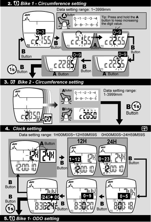
11 3. Wheel Circumference Measurement To set the wheel circumference before riding, you should measure the wheel circumference by yourself or just refer to the Wheel Circumference Table as shown below: 11
12 How do you measure the wheel circumference yourself? Roll the wheel until the valve stem is closest to the ground and mark the corresponding spot on the floor as the first point. Next, roll the wheel forward until the valve stem is closest to the ground once again. Mark the corresponding spot on the floor as the second point. Then measure the distance between both points, using the unit of millimeter. The distance equals your wheel circumference. 1. The default value of wheel circumference for Bike 1 is 2155mm; that for Bike 2 is 2050mm. Enter the correct wheel circumference into the computer in Data Setting Mode. 2. Refer to pages 13 and 14 about basic setting to set your wheel circumference. 12

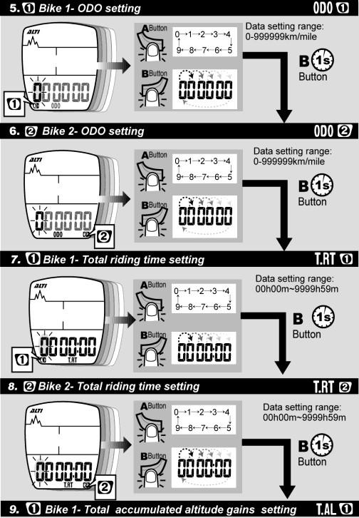
13 4. Basic Setting & Operation Tip for Data Setting : 1. Press the A button to change the value of a flickering digit. Press the B button to move to the next digit in a loop. 2. Press and hold the B button for 1 second to move to the next setting when the current setting is finished. 3. If the computer is idle during Data Setting Mode for 20 seconds, it'll automatically return to General Mode. 13
14 14
15 15
16 16

17 5. General Display The display of General Mode looks different in different phrases as shown below: 1. Put the main unit onto the bracket, and the main unit will automatically start measuring the speed and cadence. 2. The main unit will automatically enter Sleep Mode in 15 minutes once it doesn't receive any signals from the bike. 3. Only current time is displayed when the computer is in Sleep Mode (Power-Saving Mode.) 4. Press the A or B button to wake it up, and it'll show the previous display and resume measuring. 5. When the main unit is on the bracket, you cannot enter Data Setting Mode or switch between Bike 1 and Bike 2. 17
18 6. Battery Replacement 1. When the low battery indicator is shown on the display, replace the battery with a new one A.S.A.P. 2. The positive (+) pole of the CR2032 battery must face the battery cap. 3.Press buttons A, B, C for 3 seconds to initiate the main unit. Attention: When there's the low battery symbol on the screen, we suggest that you replace the battery with a new one A.S.A.P. Otherwise, the altitude measurement result may be incorrect, and the new data may be lost. 18

19 7. General Mode Display When you are riding with the computer, some functions will not be displayed on the screen. These functions like T.AL, ODO, mbar, DST/D are displayed only when you stop riding. 19

20 8. About Altitude Calibration: Tip for Quick Altitude Calibration 1. Press both A and B buttons for 1 second, and the current altitude value will return to zero. 2. Press the A button to set the value of a digit, and press the B button to move to the next digit. 3. Attention: Calibrate the current altitude only when there're no speed signals. 20


21 9. Temperature Display The following operation is for Echo-a2 only: 10. Bike 1 /Bike 2 Selection Bike 1 and Bike 2 have their separate data in the computer. 21
, Cmm2, ODO 1, ODO 2, T.RT1, T.RT2, T.AL1, T.AL2. 3.")
22 11. Data Reset 1. Press and hold the A button for 3 seconds to reset data of DST, RTM, MAX, AVG, ALT,MAX-ALT, MAX-RPM, AVG-RPM (for Echo-a2 only) 2. The following data are stored in memory and cannot be reset: Unit, Cmm1 (Circumference 1), Cmm2, ODO 1, ODO 2, T.RT1, T.RT2, T.AL1, T.AL2. 3. Reset data for Bike 1 and data for Bike 2 respectively. 22


23 12. EL Backlight 13. Sleep Mode Press the A or B button to wake it up. 23
24 Functions The display of the computer can be divided into three sections upper, middle, and lower display. In General Mode, the LCD display of your computer is as below: The current altitude is always shown on the upper display, and it's easy to calibrate it when necessary. For Echo-a1 users, current speed and temperature are always shown on the middle display. For Echo-a2 users, current speed and current RPM are always shown on the middle display. And most functions are shown on the lower display-- you may press the A button to view each function display. Regarding the functions marked with listed below, the data can be reset to zero by the reset operation. (When in General Mode, press the A button for 3 seconds to reset the computer.) ALTI Current Altitude 1. The current altitude is always displayed on the upper display. 2. To get accurate basis altitude, the cyclist should calibrate the altitude before each ride. 3. The measurement is based on the principle that atmospheric pressure decreases as elevation increases. 4. The altitude is measured by means of the atmospheric pressure, so it's weather-dependent. 5. You may obtain the altitude data from a topographic map or the Internet. 6. The altitude of the altimeter is pre-calibrated by the precise instrument at the factory before shipment. Current Speed 1. The current speed is always shown on the middle display during riding. 2. The speed data are updated per second. 3. For Bike 1, when you do not ride the bike for more than 4 seconds, the speed data will be reset to zero. 24
25 For Bike 2, when you do not ride the bike for more than 2 seconds, the speed data will be reset to zero. MAX Max. Speed 1. With this function, the computer will record the maximum speed you reach during riding. 2. Whenever you reset the computer or change the battery, the max. speed record will be cleared. AVG Average Speed 1. With this function, the computer will display your average speed during riding. 2. Whenever you reset the computer or change the battery, the average speed record will be cleared. 3. It'll display "0.0" if the riding time is below 6 seconds. 4. It's updated every second on condition that the riding time is over 6 seconds. 5. The computer will automatically reset the following data to zero once the RTM is over 100 hours or the DST is over 1000KM (or miles): RTM (riding time), DST (trip distance), AVG (average speed.) DST Trip Distance 1. DST refers to the accumulated distance during a trip. 2. Whenever you reset the computer or change the battery, the trip distance record will be cleared. RTM Riding Time 1. RTM refers to the accumulated riding time of a trip. 2. Whenever you reset the computer or change the battery, the trip distance record will be cleared. 3.The computer automatically starts measuring the riding time upon receipt of wheel signals. If you are riding your Bike 1, whenever you stop, the computer will continue to count the riding time for 4 more seconds to make sure there're no more 25
26 wheel signals. If you are riding your Bike 2, the computer will count the riding time for 2 more seconds for the same reason. Regarding the riding time it over counts, the computer will automatically deduct it and show the correct riding time. RPM Current Cadence (for Echo-a2 only) 1. RPM (Revolutions Per Minute) is a measure of rotational speed. It's updated every second. 2. The current RPM (cadence) is always shown on the middle display. 3. For Bike 1, if you do not turn the crank for over 4 seconds, the current RPM will be reset to zero. For Bike 2, if you do not turn the crank for over 2 seconds, the current RPM will be reset to zero. MAX. RPM Maximum Cadence (for Echo-a2 only) 1. With this function, the computer will record your maximum cadence during riding. 2. Whenever you reset the computer or change the battery, the max. RPM record for a trip will be cleared. *AVG RPM Average Cadence (for Echo a2 only) 1. With this function, the computer will display the average cadence during riding. It's updated per second. 2. Whenever you reset the computer or change the battery, the average cadence record will be cleared. Pace Arrow 1. The pace arrow shows the comparison between the current speed and average speed. 2. If the current speed is above or equal to the average speed, the upward arrow ( ) will flash on the display. 3. On the contrary, if the current speed is below the average speed, the downward arrow ( ) will flicker. 26
27 ALT Accumulated Altitude Gains (During a Trip) 1. With this function, it displays the accumulated altitude gains during a trip. 2. When you ride over uphill paths, the altimeter will accumulate the altitude gains. However, when you ride over downhill paths, the computer will not deduct the altitude loss. The altimeter always accumulates your altitude gains only. 3. Attention: The altitude gains are accumulated during riding only. MAX. ALT Maximum Altitude (During a Trip) 1. With this function, the computer displays the maximum altitude you reach during a trip. 2.The max. altitude record will be cleared after you reset the computer or change the battery. SCAN Auto-Scan 1. To start this function, press the A button for times until the scan icon is displayed. 2. When the SCAN icon is flashing, each function display in the lower screen will be shown in a loop. In the loop, each function will be displayed on the screen for 5 seconds. 3. You may disable the auto-scan function by pressing the A button again. DST/D Distance/ Day 1. With the DST/D function, the computer accumulates the distance of your riding in one day. 2. The DST/D data will be automatically cleared at 12:00:00 a.m. (or 0:00:00) per day. mbar Millibar (Barometer) 1. The altimeter is essentially a barometer, and millibar is a unit of atmospheric pressure. (e.g. Standard atmospheric pressure at sea level is about 1013 millibars.) 27
28 2. The altimeter converts the millibar value of atmospheric pressure into the current altitude. 3. Attention: There is a hole at the bottom of the main unit for measuring the air pressure. The hole for measurement should be always kept clean. Besides, do not poke anything into the hole to avoid damage. ODO Odometer 1. With this function, the computer accumulates the total distance of the bike you ride. 2. The odometer data cannot be cleared by the reset operation. ODO (1) + (2) Total Odometer (Bike 1 + Bike 2) 1. With this function, the computer accumulates the total distance of the two bikes you ride. 2. The sum of ODO 1 and ODO 2 equals ODO (1) (2). (i.e. total distance of bikes 1 and 2) 3. The total odometer data cannot be cleared by the reset operation. T. RT Total Riding Time 1. With this function, the computer accumulates the total riding time of a bike. 2. The total riding time data cannot be cleared by the reset operation. T.RT (1)+(2) Total Riding Time (Bike 1 + Bike 2) 1. With this function, the computer accumulates the total riding time of the two bikes you ride. 2. The sum of T.RT 1 and T.RT 2 equals T.RT (1) (2). (i.e. total riding time of bikes 1 and 2) 3. The accumulated total riding time of Bike 1 and Bike 2 cannot be cleared by the reset operation. 28
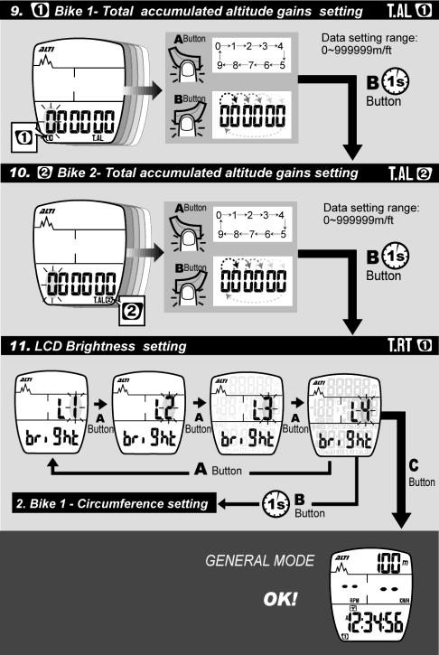
29 T.AL Total Accumulated Altitude Gains 1. It displays the total accumulated altitude gains during all previous trips. 2. The accumulated altitude gains cannot be cleared by the reset operation. T.AL (1)+(2) Total Accumulated Altitude Gains (Bike 1 + Bike 2) 1. It displays the total altitude gains accumulated during all previous trips of the two bikes you ride. 2. The sum of T.AL 1 and T.AL 2 equals T.AL (1) (2). (i.e. total accumulated altitude gains of bikes 1 and 2) 3. The accumulated altitude gains cannot be cleared by the reset operation. A/P Clock Time: 12H/24H Alternative 1. When the user sets the clock time in Data Setting Mode, there are two formats for option-- 12H and 24H H means 12 hours. In this format, A refers to AM; P refers to PM. 24H means 24 hours. 3. When in the sleep mode, only the clock time will be displayed on the screen. 0 C/ 0 F Current Temperature 1. In General Mode, the current temperature is always shown on the middle display of Echo-a1. 2. If you are the Echo-a2 user, press the B button for 1 second and you'll view the current temperature. 29
30 Low Battery Indicator 1. When the low-battery indicator appears on the display, it's time to get a new battery. 2. Replace the battery with a new one A.S.A.P. when the symbol blinks on the display. Otherwise, the new data of some functions will not be stored into the computer. 3. If you do not change the battery in a few hours, the computer may still work for a few days. The data will be displayed as usual, but the new data will not be stored before the battery is changed. 4. To save battery power, there's no EL backlight when the low-battery symbol is blinking. LOW Technical Specifications Symbol Function Range Current Speed Average Speed for Bike 1 Average Speed for Bike 2 Maximum Speed for Bike 1 Maximum Speed for Bike 2 Pace Arrow Trip Distance for Bike 1 Trip Distance for Bike 2 Odometer for Bike 1 Odometer for Bike 2 Total Odometer (Bike 1 + Bike 2) km/h ( m/h) km/h ( m/h) km/h ( m/h) km/h ( m/h) km/h ( m/h) Compared with average speed km/mile km/mile km/mile km/mile km/mile 30
31 Distance Per Day km/mile Riding Time for Bike 1 Riding Time for Bike 2 Total Riding Time for Bike 1 Total Riding Time for Bike 2 Total Riding Time (Bike 1 + Bike 2) 0H:00M:00S-99H:59M:59S 0H:00M:00S-99H:59M:59S 0H:00M:-9999H:59M 0H:00M:-9999H:59M 0H:00M-19999H:59M Current Altitude Accumulated Altitude Gains for Bike 1 Accumulated Altitude Gains for Bike 2 Maximum Altitude for Bike 1 Maximum Altitude for Bike 2 Total Accumulated Altitude Gains for Bike 1 Total Accumulated Altitude Gains for Bike 2 Total Accumulated Altitude Gains (Bike 1+ Bike 2) Barometer Unit Selection Current Temperature m m (-1640ft ft) UNIT:1m/3ft m ( ft) m ( ft) -500m m (-1640ft ft) -500m m (-1640ft ft) m ( ft) m ( ft) m ( ft) mbar Meter/feet, C/ F, kilometer/mile -10 C ~ 60 C (14 F ~ 140 C)
32 Circumference for Bike 1 Circumference for Bike 2 12/24H Clock Auto-Scan Low Battery Indicator EL Back-light LCD Brightness Levels mm (default: 2155mm) mm (default: 2050mm) 1H:00M:00S-12H:59M:59S, 0H:00M:00S-23H:59M:59S Automatically shifted to the next per 5 seconds Light for 3 seconds after each press * The following RPM (cadence) functions are for Echo-a2 only: Current RPM 0-199RPM Maximum RPM for Bike 1 Maximum RPM for Bike 2 Average RPM for Bike 1 Average RPM for Bike RPM 0-199RPM 0-199RPM 0-199RPM 32
33 General Specifications Operating Temperature Storage Temperature: Sensor & Transmitter: 0 C - 50 C (32 F F) -10 C - 60 C (14 F F) No-contact magnet sensor with wireless transmitter Suitable Fork Sizes: 12 mm - 50 mm (0.5" - 2.0") Battery Operating Life: CR2032 in Main Unit About one year (based on the average riding time of 1.5 hours per day) CR2032 in Speed Transmitter Around km (15000 miles) CR2032 in RPM Transmitter Around 600 hours Dimensions & Weight (Main Unit): 46 x 57.3 x 19.7 mm, g The specifications and design are subject to change without prior notice. 33
34 Precautions 1. Watch the road. Don't pay much attention to your cycle computer functions during riding to avoid accidents. 2. Don't expose the main unit to direct sunlight for a long time while you're not riding with it. 3. Never disassemble the device or the accessories. 4. Don't poke a needle or any pointed article into the hole on the bottom of the main unit. To poke anything into the hole may damage the pressure sensor inside the device. 5. Check the positions of the sensor and magnet, and check the gap between both parts regularly. Make sure they are always in normal condition. 6. Use a dry or slightly damp cloth to clean the computer when necessary. Do not use thinner, alcohol or benzine to clean the product. 7. Do not operate the computer under water though it's waterproof. Note there are sensitive components inside the main unit. 8. Be alert to the sudden weather change during long-distance riding to avoid danger. And sudden change in temperature may cause a temporary incorrect altitude display. 34
35 Trouble Shooting Problem No display Check the following: 1.Is the battery dead? 2.Is the battery installation correct? Solutions 1.Replace the battery with a new one. 2.Make sure the positive pole of the battery faces the battery cap. Speed not displayed or wrong displayed 1.Is the computer in the 1. Refer to the setting setting mode? procedures to finish the 2.Are the magnet and setting. the sensor in the 2.Refer to the installation correct position? Is manual and correct the the gap between positions and gap. both parts correct? 3. Refer to "Wheel 3. Is the wheel Circumference circumference Measurement and Setting" setting correct? and enter a correct value. 4. Is the sensing 4. Refer to the installation distance between manual and adjust the the main unit and the distance sensor too long? between the main unit and 5. Is the battery for the the sensor or adjust the sensor nearly angle of the sensor. exhausted? 5. Replace the battery with a 6. Is there any strong new one. interference source 6. Stay away from the strong nearby? interference source. Irregular Display Refer to "Main Unit Setup" and initiate the computer again. 35
36 LCD is black. Display is slow. Low-battery symbol is blinking. Did you expose the Put the main unit in the shade main unit to the direct to let it return to normal state. sunlight for a long time when it was not in use? Is the temperature below 0 0 C (32 0 F)? The computer will return to normal state when the temperature rises. Replace the battery in the main unit with a new one. Altitude not displayed or wrong displayed 1. Did you calibrate the altitude before riding? 2.Is the hole for measuring the air pressure on the bottom of the main unit clean? 1.Refer to "Overview of Button Operation" and calibrate the altitude before each ride. 2.Always keep the hole for measuring the air pressure clean. Do not poke anything into the hole to avoid damage. 36
wireless computer owner s manual 80mm x 110mm Black
 wireless computer owner s manual 80mm x 110mm Black Contents Package Contents... 3 Using Your Computer... 4 1.Main Unit Setup... 4 1. Initiation of Main Unit 2. Basic Display Modes 2. Overview of Button
Heart Rate 1. Calories 3. Current Altitude Parts. Set Home Altitude 5. Clock. Ascent% 7. Average Display. Date. Maximum Speed 13
 - English - Content Heart Rate 1 Introduction Reset Trip Data 31 Set Smart EL Calories 3 Unit 17 Enter Setting Mode Power Calibration 47 Current Altitude Parts 19 Set Clock 33 Mode / Sub Mode Functions
Wireless Console User Guide Instructions for use with the Universal Trainer and Speed/Cadence Sensor
 Wireless Console User Guide Instructions for use with the Universal Trainer and Speed/Cadence Sensor A. Parts list ⓵ 1. Wireless Console (WC) 2. Batteries 3. Speed/Cadence Sensor (SCS) 4. Crank arm magnet
Introduction. Pack contents
 MC 2.0 PL NL ES IT FR ENG DE MC 2.0 WR DE Bedienungsanleitung ENG Instruction Manual FR Manuel d Installation et d Utilisation IT Manuale d Installazione e Funzionamento ES Instalacion y operación manual
CATEYE PADRONE+ CYCLOCOMPUTER CC-PA110W. Mounting the. computer. Setting up the. computer. Starting measurement. Changing settings
 Mounting the computer CATEYE PADRONE+ CYCLOCOMPUTER CC-PA110W Setting up the computer Starting measurement Changing settings This instruction manual is subject to change without notice. See our website
Star Trac Group Cycling Computer Owner s Manual and Installation Guide
 Star Trac Group Cycling Computer Owner s Manual and Installation Guide 700-0008 NOTE: When printing this manual from a PDF file, print using booklet style printing to print a folded, 5.5 x 8.5 manual on
VEHICLE DISPLAY Manual
 VEHICLE DISPLAY Manual W108 1 Contents Preface 3 Appearance & size 4 Material & color 4 Function & button 4 Function 4 Interface 5 Button 5 Attentions 6 Installation 6 ON/OFF 6 Walking Assist 7 Backlight
C p 9051 SerieS CyCle ComputerS
 Series Cycle computers CP9051 EXTRA LARGE XXL digits EASY-TO-USE Data SAFE during battery change Low battery INDICATOR Display backlight Digital wireless transmission Heart rate profile graph Altitude
Contents. 1. Safety Description Specifications Operation Instructions Battery Replacement...20.
 Contents Contents 1. Safety....1 2........4 2.1 Meter......4 2.2 Display......8 3. Specifications.....10 3.1 Range and Precision.....10 3.2 Measurement Method.....10 3.3 Using Temperature and Humidity.....10
QUICK START GUIDE. AStrO. Ver Toll Free : 1 (877) Visit :
 Visit :") QUICK START GUIDE AStrO Ver.10.309 Toll Free : 1 (877) 462-7296 Visit : 1 Thank you for purchasing the latest in data acquisition technology, the AStrO. We hope that it surpasses your expectations. This
QUICK START GUIDE AStrO Ver.10.309 Toll Free : 1 (877) 462-7296 Visit : 1 Thank you for purchasing the latest in data acquisition technology, the AStrO. We hope that it surpasses your expectations. This
433 MHZ REMOTE THERMO
 433 MHZ REMOTE THERMO INTRODUCTION: Congratulations on purchasing this innovative 433MHz Remote Thermo which displays the time with up to the minute indoor and up to five outdoor temperature readings.
1: Introduction : Caution : Tips for Reading this Manual : Preface : System Highlights : Receiver
 1: Introduction....1 1 2: Caution.... 2 2 3: Tips for Reading this Manual....3 3 4: Preface....4 4 5: System Highlights....6 6 6: Receiver..7 7 6.1: Specifications......7 7 6.2: Receiver Operation... 7
CXC CONSOLE. MX18_OM_CXC_console_r1_1_A.indd 1
 CXC CONSOLE MX18_OM_CXC_console_r1_1_A.indd 1 3/1/18 8:42 AM Hardware FEATURES CONSOLE A B C D Description Screw (M5x10L) Magnet Screw (M4x6L) Screw (M5x12L) Qty 1 1 2 3 ANT+ interoperable 2.4Ghz wireless
INSTRUCTION MANUAL Version 1.0
 INSTRUCTION MANUAL Version 1.0 Camera Geotagger For Nikon or Canon GPS plus Beidou Barometric altimeter Position Tracing Logger Shutter Release Remoter LCD display Bluetooth technology GPS Contents Introduction
GMI 10. quick start manual
 GMI 10 quick start manual Introduction The GMI 10 allows you to quickly view important information about your boat provided by connected sensors. Connected sensors transmit data to the GMI 10 using NMEA
Wireless Pressure Station with Backlight
 Wireless Pressure Station with Backlight FORECAST RELATIVE PRESSURE PRESSURE HISTORY inhg -24h -18h -12h -9h- 6h -3h0 h INDOOR For online video support: http://bit.ly/laxtechtalk Model: 308-1417BL DC:
Operation Guide 3721
 MA0410-EA Modes and Hand Movement Each press of the B button sounds a confirmation tone and cycles through available modes in the sequence shown below. The watch will revert to the Timekeeping Mode automatically
Please read carefuly before using. Aerobic Lateral Trainer ASSEMBLY MANUAL H901
 Please read carefuly before using. Aerobic Lateral Trainer ASSEMBLY MANUAL H901 TABLE OF CONTENTS 1 IMPORTANT SAFETY INFORMATION 2 Important Safety Precautions 2 Weight Limit Capacities 2 Warning 2 2
Operation Guide 3452
 MA1804-EA Contents Before Getting Started... Button Operations Mode Overview Charging the Watch Solar Charging Charging with the Charger Charging Time Guidelines Checking the Charge Level Power Saving
GETTING STARTED. Radio layout. LCD display with icons
 GETTING STARTED Radio layout LCD display with icons 1. Key lock button 2. Battery meter 3. Main channel indicator 4. Scan icon 5. Roger beep indicator 6. CTCSS sub-channel indicator 7. VOX indicator 1
A3 Pro INSTRUCTION MANUAL. Oct 25, 2017 Revision IMPORTANT NOTES
 A3 Pro INSTRUCTION MANUAL Oct 25, 2017 Revision IMPORTANT NOTES 1. Radio controlled (R/C) models are not toys! The propellers rotate at high speed and pose potential risk. They may cause severe injury
Wireless Copilot. Safe2Fly - Height Only Version. Page NanoQuip Ltd
 Wireless Copilot Safe2Fly - Height Only Version Page Contents Warnings... 3 Features... 4 Specifications... 5 Installation... 6-8 Receiver Battery... 6 Transmitter Installation... 7-8 How to Use This Manual...
ICM/ICAD Motorized Valve. Quick Start Guide. Installation, Programming, and Trouble-shooting REFRIGERATION & AIR-CONDITIONING
 Installation, Programming, and Trouble-shooting REFRIGERATION & AIR-CONDITIONING Quick Start Guide Contents Page Installation...............................................................................................3
WS-7136U Wireless 433 MHz Temperature Station. Instruction Manual
 WS-7136U Wireless 433 MHz Temperature Station Instruction Manual TABLE OF CONTENTS Topic Page Inventory of Contents 3 Additional Equipment 4 Quick Setup 5-9 Detailed Setup Guide Battery Installation 10-12
TM Quick Start Guide
 TM Quick Start Guide Contacting Pazzles By Phone In the US: 866-729-9537 International: +1-208-922-3558 Phone Hours: Mon - Fri, 9am - 5pm Mountain Time By Email Customer Service: Technical Support: Sales:
USER GUIDE WS Weather station with wireless outdoor sensor. 433MHz
 USER GUIDE 433MHz Weather station with wireless outdoor sensor WS-1650 RESET MODE UP DOWN NEXT C/ F CHANNEL CLOCK LIGHT RESET OVERVIEW A B 5 C 5 MODE UP DOWN NEXT C/ F CHANELCLOCK DC 4.5V 1 4 3 D 2 6 E
impact VC-500LR Monolight INSTRUCTIONS
 impact lighting equipment and accessories VC-500LR Monolight INSTRUCTIONS Congratulations on your purchase of the Impact VC-500LR Monolight. We feel that it will contribute much to your photographic skill
Important safety instructions
 RCR-29 GB Version 1 Important safety instructions VERY IMPORTANT PLEASE READ Sangean suggest that you keep your AC Adapter at least 12 inches away from the radio while listening to the AM Band. Your Sangean
Wireless Color Weather Station
 Wireless Color Weather Station INSTRUCTION MANUAL MODEL: C85845V3 DC: 120518 FIND MANUALS, FAQS, AND MORE UNDER THE SUPPORT TAB HERE: bit.ly/c85845v3 TABLE OF CONTENTS 3. Power Up 3. LCD Features 4. Buttons
Expandable Series Wireless Multi Unit Doorbell System
 Expandable Series Wireless Multi Unit Doorbell System Thank you for purchasing our Wireless Doorbell system. Please carefully read this user manual before usage and installation. North America Office:
User manual. paper moisture meter RH5.1 with sword-sensor
 User manual paper moisture meter RH5.1 with sword-sensor version 2.0_en Schaller GmbH 2012 User manual Positioning the instrument Insert the sword-sensor into the stack for only approx. 10 cm, and push
WIRELESS Energy Monitor - Smart Meter
 Energy saving made simple MONITOR CONTROL SAVE WIRELESS Energy Monitor - Smart Meter Monitors your electricity use and cost in real time Instruction Manual EW4500 IMPORTANT Please retain your Instruction
RTS Reactive Target System
 RTS Reactive Target System RTS Electronic Target System Operating and User s Manual Introduction RTS (Reactive Target System) introduces a significant technological leap in erecting and managing wireless
Full Weather Station with Radio Controlled Clock, Projection and AM/FM Radio (Model #: PS-L06 / PS-L06U) User Manual
 User Manual") Full Weather Station with Radio Controlled Clock, Projection and AM/FM Radio (Model #: PS-L06 / PS-L06U) User Manual 1 2 TABLE OF CONTENTS About this guide... 2 Product overview... 3 Getting started...
Full Weather Station with Radio Controlled Clock, Projection and AM/FM Radio (Model #: PS-L06 / PS-L06U) User Manual 1 2 TABLE OF CONTENTS About this guide... 2 Product overview... 3 Getting started...
WIRELESS 868 MHz TEMPERATURE STATION Instruction Manual
 WIRELESS 868 MHz TEMPERATURE STATION Instruction Manual INTRODUCTION: Congratulations on purchasing this compact 868MHz Temperature Station which displays radio controlled time, date, indoor and outdoor
CITIZEN QUARTZ Magic Light. Model No. JQ5XXX Cal. No. C430. Instruction Manual CTZ-B6779
 CITIZEN QUARTZ Magic Light Model No. JQ5XXX Cal. No. C430 Instruction Manual CTZ-B6779 Thank you for purchasing a CITIZEN QUARTZ WATCH. To ensure correct use, please read these instructions carefully.
WS-7212NU Wireless 433 MHz Weather Station. Instruction Manual
 WS-7212NU Wireless 433 MHz Weather Station Instruction Manual TABLE OF CONTENTS Topic Page Inventory of Contents 3 Additional Equipment 4 Quick Setup Guide 5-9 Function Keys 5 Detailed Set-up Guide 10-15
TPW288. Transmitter Transmission frequency: MHz Range of up to 50m Battery: 2 x AAA.UM04/LR03 (not included)
") . TPW288 FEATURES Radio controlled Clock DCF77 Automatic time signal receiving to display exact time with automatic winter/summer time change. Time format 12 or 24 hour format Time Zone setting from -12
. TPW288 FEATURES Radio controlled Clock DCF77 Automatic time signal receiving to display exact time with automatic winter/summer time change. Time format 12 or 24 hour format Time Zone setting from -12
A510S Operation Manual
 A510S Operation Manual REV 1.1 1 Table of Contents 1 General Information 1-1 Description 1-2 Potential Operational Hazards 1-3 Technical Specifications 1-4 Instrument Overview 1-5 Function Summary 2 How
INSTRUCTION MANUAL INF Fax: (503)
") INSTRUCTION MANUAL INF151 1-800-547-5740 Fax: (503) 643-6322 www.ueiautomotive.com email: info@ueitest.com Introduction Congratulations on your purchase of the INF151 infrared thermometer. Like all UEi
INSTRUCTION MANUAL INF151 1-800-547-5740 Fax: (503) 643-6322 www.ueiautomotive.com email: info@ueitest.com Introduction Congratulations on your purchase of the INF151 infrared thermometer. Like all UEi
Atomic Forecast Station with Moon Phase
 Atomic Forecast Station with Moon Phase For online video support: http://bit.ly/laxtechtalk Model: S84107 Instruction Manual DC: 080817 Welcome to the La Crosse Technology family! We hope you enjoy your
AIRCRAFTSCALES.COM WIRELESS WEIGHING INSTRUCTIONS.
 AIRCRAFTSCALES.COM WIRELESS WEIGHING INSTRUCTIONS. HH2400-3-xxCS Wireless scale system www.aircraftscales.com 561-281-6179 1 INTRODUCTION Thank you for your purchase of our wireless scale system please
Wholesale Chess Basic Digital Chess Timer with Bonus and Delay. User Manual
 Wholesale Chess Basic Digital Chess Timer with Bonus and Delay User Manual [1] Wholesale Chess Basic Digital Chess Timer with Bonus and Delay The Wholesale Chess Basic Digital Timer with bonus and delay
OWNER S MANUAL FM HANDHELD TRANSCEIVER
 , OWNER S MANUAL RPU4200A FM HANDHELD TRANSCEIVER NOTE, OWNER S MANUAL RPU4200A FM HANDHELD TRANSCEIVER We are very grateful for your purchasing brand twoway radios produced by Relm Wireless Corporation.
Geotagger N3. User Manual (V1.0) Revised by Geosolve.be (Pol F. Gillard) with personal updates and help. Solmeta Technology Co.
 Revised by Geosolve.be (Pol F. Gillard) with personal updates and help. Solmeta Technology Co.") Geotagger N3 User Manual (V1.0) Revised by Geosolve.be (Pol F. Gillard) with personal updates and help Solmeta Technology Co., Ltd Copyright 2011 Solmeta Technology Co., Ltd. All Rights Reserved 1 Contents
Geotagger N3 User Manual (V1.0) Revised by Geosolve.be (Pol F. Gillard) with personal updates and help Solmeta Technology Co., Ltd Copyright 2011 Solmeta Technology Co., Ltd. All Rights Reserved 1 Contents
INSTALLATION INSTRUCTIONS
 XMOD 23 Mode Rapid Fire Mod Chip INSTALLATION INSTRUCTIONS This tutorial is designed to aid you in the installation of a XMOD Rapid Fire microchip. This installation requires soldering several wires to
S-COR. FIGURE 1 Wiring Diagram NOTE: To reset S-COR to factory settings, press and! hold < and > buttons upon power up. INSTALLATION INSTRUCTIONS
 Section 1 General Description The ClearPath Spectrum Wireless System is comprised of two devices; a Coordinator () that functions in a similar role as traditional wireless system receivers, and a Transceiver
INTRODUCTION TO WEARABLES
 Table of Contents 6 7 8 About this series Getting setup Making a circuit Adding a switch Sewing on components Complete a wearable circuit Adding more LEDs Make detachable parts......6.7.8 About this series
STOP! READ THIS FIRST
 STOP! READ THIS FIRST 1 Getting Started With Your Meistergram Embroidery System (the quick guide) Thank you for choosing Pantograms for your embroidery system provider. We encourage you to read the following
Controls. LCD display A B C D E F
 H205 Version 1 1 2 3 4 5 6 13 12 11 7 8 9 10 14 15 17 18 16 1 19 Controls 1 2 3 4 5 6 7 8 9 10 11 12 13 14 15 16 17 18 19 Carrying strap holder Preset 1 Preset 2 Preset 3/STEP button Preset 4 LCD display
PEN TYPE DIGITAL MULTIMETER OPERATION MANUAL T8211D
 PEN TYPE DIGITAL MULTIMETER OPERATION MANUAL T8211D T8211D 1 1. SAFETY INFORMATION BE EXTREMELY CAREFUL IN THE USE OF THIS METER. Improper use of this device can result in electric shock or destroy of
Infrared Gun. Perfect For. Easy To Use. Features. Get Professional Results Every Time! Battery Installation. Model: IN1022
 Model: IN1022 Infrared Gun -76 to +1022 F/-60 to +550 C Perfect For Non-contact surface temperatures Easy To Use 1-second response Laser target illumination Backlit Data-hold One-button operation Features
Pipe Laser Model No Instruction Manual
 Pipe Laser Model No. 40-6690 Instruction Manual Congratulations on your choice of this Pipe Laser. We suggest you read this instruction manual thoroughly before using the pipe laser. Save this instruction
PIN/PINLESS DEEP SENSING MOISTURE METER WITH SPHERICAL SENSOR AND REMOTE PROBE
 99 Washington Street Melrose, MA 02176 Phone 781-665-1400 Toll Free 1-800-517-8431 Visit us at www.testequipmentdepot.com PIN/PINLESS DEEP SENSING MOISTURE METER WITH SPHERICAL SENSOR AND REMOTE PROBE
Operating instructions. Radio weather station
 Operating instructions Radio weather station 0334.. Notes regarding the battery Batteries and button cells do not belong in the hands of children. Contact a doctor immediately if a button cell has been
Important safety instructions
 MMR-88 Version 1 Important safety instructions 1. 2. 3. 4. 5. 6. 7. 8. 9. Please read these instructions carefully. Please keep these instructions for future reference. Heed all warnings Follow all instructions
Wireless Pressure Station
 Wireless Pressure Station FORECAST RELATIVE PRESSURE PRESSURE HISTORY inhg -24h -18h -12h -9h- 6h -3h0 h INDOOR For online video support: http://bit.ly/laxtechtalk Model: 308-1417 DC: 111517 Table of Contents
MS2302. Digital Earth Resistance Tester
 MS2302 Digital Earth Resistance Tester OPERATING INSTRUCTION PRECISION MASTECH ENTERPRISES CO. Unit 8, 21/FL, Yen Sheng Center, 64 Hoi Yuen Road, Kwun Tong, Kowloon, Hong Kong. Tel: 852-23430007 Fax:852-23436217
Energate Foundation Meter Data Collector Installation Guide
 Energate Foundation Meter Data Collector Installation Guide The Meter Data Collector works with Foundation s built-in Meter Data Receiver. The collector attaches to the meter provided by your electricity
QUANTUM Qflash T2 / X2 OPERATING INSTRUCTIONS
 QUANTUM Qflash T2 / X2 OPERATING INSTRUCTIONS 1.0 DESIGNATIONS T2 AND X2 1. Removable Reflector, two positions Normal and Wide angle. 2. Flash-tube 2A. Modeling Lamp (for Model X2 only) 3. Bounce Head,
WIRELESS 433MHZ WEATHER STATION
 WIRELESS 433MHZ WEATHER STATION INTRODUCTION: Congratulations on purchasing this Weather Station with wireless 433MHz, which displays time/date, indoor/outdoor temperature and humidity, and receives up
Model: TP380 User Manual
 Model: TP380 User Manual 1 UHF RADIO TRANSCEIVER MODEL: TP380 USER MANUAL INTRODUCTION Thank you for selecting the Oregon Scientific TP380 as your product of choice. This product is a portable, easy-to-use
Two-Way Radios. Quick Start Guide. XT460 Display model
 Two-Way Radios Quick Start Guide XT460 Display model CONTENTS Contents..................................... 1 Safety....................................... 2 Batteries and Chargers Safety Information........
1200 DPS Programmable Digital Powder System
 1200 DPS Programmable Digital Powder System WARNINGS AND CAUTIONS: If the 1200 DPS does not read zero on the display, DO NOT DISPENSE POWDER. The scale must be zeroed before use. If powder is dispensed
Digital Wireless Weather System
 Digital Wireless Weather System Thermometer, Hygrometer and Heat Index with Remote Sensor Leading the Way in Accuracy 1458 Instruction Manual C H CHANNEL Congratulations on your purchase of the Taylor
User s Manual. For correct usage please read these instructions carefully and keeps in a safe place for future reference!
 User s Manual For correct usage please read these instructions carefully and keeps in a safe place for future reference! Contents 1: Safety precautions... 2 2: Package contents... 3 3: Description of parts...
Schwinn Cadence Pro TM Console. Installation & Instructions
 Schwinn Cadence Pro TM Console Installation & Instructions Table of Contents Components in the Box...3 Tools Required for Assembly...4 Specifications...4 Warranty and Customer Support...4 Certifications...5
Sensor. Wireless WR-CLIK. WRF-CLIK Wireless Rain/Freeze-Clik. Rain Sensor Shutoff for Automatic Irrigation Systems
 Wireless RAIN LIKTM Sensor Rain Sensor Shutoff for Automatic Irrigation Systems Owner s Manual and Installation Instructions WR-CLIK Wireless Rain-Clik WRF-CLIK Wireless Rain/Freeze-Clik TABLE OF CONTENTS
MS8211 DIGITAL MULTIMETER INSTRUCTION MANUAL
 MS8211 DIGITAL MULTIMETER INSTRUCTION MANUAL Ω CONTENTS CONTENTS 1. SAFETY INFORM...1 4.4 Range Transform...10 1.1 Preliminary...1 4.5 Auto Power Off...10 1.2 During use...2 4.6 Preparation For Measurement...11
PowerCost Monitor. Installation Guide. Install the Batteries in the Display Unit. Install the Batteries in the Sensor Unit
 PowerCost Monitor Installation Guide Welcome Congratulations on your purchase of the PowerCost Monitor, a new electricity-monitoring device that informs you in real time of the amount of electricity your
WIRELESS 868 MHz TEMPERATURE STATION Instruction Manual
 WIRELESS 868 MHz TEMPERATURE STATION Instruction Manual INTRODUCTION: Congratulations on purchasing this temperature station with wireless 868MHz transmission. It not only displays the indoor temperature
PR-D9CL. GB Version 1
 PR-D9CL GB Version 1 Table of contents Important safety instructions... 2-3 Controls... 4-6 Operating your radio Search tuning AM / FM... 8 Manual tuning AM / FM / Setting up the tuning step increment...
FX-70 TWIN PMR 446. Instruction manual. English manual
 FX-70 TWIN PMR 446 Instruction manual English manual 1.Fitting the Battery pack 2.How to fix the unit into the wristbelt.charging the battery pack 6 6 8 4.Using the Stopwatch 5.Using the Personal Mobile
ET Water SmartWorks Panel Installation Guide
 ET Water SmartWorks Panel Installation Guide You are installing a new piece of equipment that retrofits into an existing irrigation controller in order to create a weather-based irrigation control system.
2. Working Voltage and Mode of Connection 2.1 Working Voltage: DC24V 36V 48V (set by the meter), other voltage could be customized.
, other voltage could be customized.") LCD-SW900 INSTRUCTIONS 1. Shell s Size and Material The shell s material is ABS. LCD screen is made of imported high hardness acrylic, and the hardness is equal to the tempered glass. Front View Side View
LCD-SW900 INSTRUCTIONS 1. Shell s Size and Material The shell s material is ABS. LCD screen is made of imported high hardness acrylic, and the hardness is equal to the tempered glass. Front View Side View
Expandable Controller 3, 7, 11, 15 stations Installation and Programming Guide
 seconds. This blinking cycle is to go on until the low battery condition is corrected. At that time the normal display returns. Also, while LO BA is blinking, if the dial is turned or any button is pressed,
Home Automation, Inc. Model 12A00. Wireless Receiver. Installation Manual
 Home Automation, Inc. Model 12A00 Wireless Receiver Installation Manual Document Number 12I00 Rev D August, 2002 CONTENTS DESCRIPTION...1 COMPATIBLE TRANSMITTERS...1 INSTALLATION...2 OPERATION...3 SETUP
WR120 Owner s Manual Guide du propriétaire Manual de instrucciones
 WR120 Owner s Manual Guide du propriétaire Manual de instrucciones Midland Radio Corporation 5900 Parretta Drive Kansas City, MO 64120 Tel. (816) 241-8500 All Hazards Alert Weather Radio with S.A.M.E Quick
RAIN-CLIK. Rain Sensor With Optional Freeze Shutoff for Automatic Irrigation Systems. Owner s Manual and Installation Instructions
 RAIN-CLIK Rain Sensor With Optional Freeze Shutoff for Automatic Irrigation Systems Owner s Manual and Installation Instructions For use with WR-CLIK and WRF-CLIK Sensors TABLE OF CONTENTS Features...3
Mist. now you know. Clock Radio with Weather Forecast. Quick Start Guide and User Manual
 Mist Clock Radio with Weather Forecast Quick Start Guide and User Manual now you know. Contents 2 Welcome to Ambient Devices! 3 Quick Start Guide 5 Getting to know your Mist Clock Radio 8 Using your Mist
STX Stair lighting controller.
 Stair lighting controller STX-1792 STX-1792 controller is used to control stairs lighting dynamically. The backlight is switched on with the subsequent steps, depending on the motion directions: ascending
ATOMIC WALL CLOCK with REMOTE TEMPERATURE SENSOR Model CL Instruction Manual
 ATOMIC WALL CLOCK with REMOTE TEMPERATURE SENSOR Model CL030027 Instruction Manual Congratulations on purchasing your ATOMIC CLOCK with REMOTE TEMPERATURE SENSOR. Please read these instructions carefully
WS-7220U-IT 915 MHz Wireless Weather Station. Instruction Manual
 WS-7220U-IT 915 MHz Wireless Weather Station Instruction Manual 1 TABLE OF CONTENTS Introduction..3 Inventory of Contents 4 Quick Set Up 4 Detailed Set Up 4-5 Battery Installation....4-5 12 or 24 Hour
One connected to the trainer port, MagTrack should be configured, please see Configuration section on this manual.
 MagTrack R Head Tracking System Instruction Manual ABSTRACT MagTrack R is a magnetic Head Track system intended to be used for FPV flight. The system measures the components of the magnetic earth field
CITIZEN QUARTZ WINGMAN V. Model No. JQ2XXX/ Cal. No. C420 INSTRUCTION MANUAL CTZ-E6793
 CITIZEN QUARTZ WINGMAN V Model No. JQ2XXX/ Cal. No. C420 INSTRUCTION MANUAL CTZ-E6793 3. SETTING THE ANALOG TIME DISPLAY 1. Pull out the crown and stop the seconds hand. 2. Turn the crown and set the hands
ADVANCED USER S GUIDE
 ADVANCED USER S GUIDE DCP-J125 DCP-J315W Version 0 ARL/ASA/NZ/SAF User's Guides and where do I find it? Which manual? What's in it? Where is it? Safety and Legal Quick Setup Guide Basic User's Guide Advanced
Heavy Duty CFM-CMM Thermo-Anemometer With built-in non-contact IR Thermometer and Laser Pointer Model HD300
 User Guide Heavy Duty CFM-CMM Thermo-Anemometer With built-in non-contact IR Thermometer and Laser Pointer Model HD300 Introduction Congratulations on your purchase of the Extech HD300 CFM Thermo-Anemometer.
EXAMINER+ Manual V.1. ARROWHEAD FORENSICS Strang Line Road Lenexa, Kansas PHONE FAX
 P A R T O F T H E E L I T E S E R I E S ARROWHEAD FORENSICS 11030 Strang Line Road Lenexa, Kansas 66215 PHONE 913.894.8388 FAX 913.894.8399 www.arrowheadforensics.com EXAMINER+ Manual V.1 CONTENTS: Canon
ELECTRIC SLIP ROLL MACHINE. Model: ESR-1300X2.5/ESR-1300X4.5 ESR-1550X3.5/ESR-1580X2.0
 ELECTRIC SLIP ROLL MACHINE Model: ESR-1300X2.5/ESR-1300X4.5 ESR-1550X3.5/ESR-1580X2.0 Operation Manual Table of contents I MAIN SPECIFICATION...2 II SAFETY INSTRUCTIONS.. 2 III OPERATION INSTRUCTIONS..4
THE BENCHMARK OF QUALITY, PRECISION, STYLE AND VALUE OWNERS MANUAL AND WARRANTY INFORMATION
 THE BENCHMARK OF QUALITY, PRECISION, STYLE AND VALUE OWNERS MANUAL AND WARRANTY INFORMATION Table of Contents 2. Congratulations 3. Helpful Terms 4.-5. Water Resistance 6.-7.-8.-9 Basic Instructions 10.-11.
AP-N1001 FLASH USER S MANUAL
 AP-N1001 FLASH USER S MANUAL For video tutorials about your product(s), customer support, updated user manuals, and all other Altura Photo news please visit: www.alturaphoto.com FEATURES Guide Number:
Circuit Board Assembly Instructions for Babuinobot 1.0
 Circuit Board Assembly Instructions for Babuinobot 1.0 Brett Nelson January 2010 1 Features Sensor4 input Sensor3 input Sensor2 input 5v power bus Sensor1 input Do not exceed 5v Ground power bus Programming
D-808. FM Stereo/LW/MW/SW-SSB AIR RDS Synthesized Receiver
 XHDATA D-808 FM Stereo/LW/MW/SW-SSB AIR RDS Synthesized Receiver WARNING Do not expose this appliance to rain or moisture Do not submerge or expose to water Protect from high humidity and rain Only operate
SERVICE MANUAL PARTS LIST MODEL: NH40
 SERVICE MANUAL & PARTS LIST MODEL: NH40 CONTENTS What to do when... 1-3 SERVICE ACCESS Face Cover... 4 Bed Cover... 5 Free-arm Cover... 6 Front Cover... 7 Rear Cover... 8 MECHANICAL ADJUSTMENT Presser
Always there to help you. Register your product and get support at AJB4300. Question? Contact Philips.
 Always there to help you Register your product and get support at www.philips.com/support Question? Contact Philips AJB4300 User manual Contents 1 Important 2 Safety 2 2 Your FM/DAB+ clock radio 3 Introduction
CONTENTS. La Crosse Technology, Ltd. Page 1
 WT-5220U-IT FAQS The links below will work in most PDF viewers and link to the topic area by clicking the link. We recommend Adobe Reader version 10 or greater available at: http://get.adobe.com/reader
WIRELESS 868 MHz WEATHER STATION
 WIRELESS 868 MHz WEATHER STATION Instructions Manual INTRODUCTION: Congratulations on purchasing this Weather Station with wireless 868 MHz transmission of outdoor temperature and display of indoor temperature,
CONTENTS. Accessories and Components System Unit and Joystick Assembly and Charging the Battery Jeotech Using Phases...
 CONTENTS Accessories and Components... 3 System Unit and Joystick... 4 Assembly and Charging the Battery... 6 Jeotech Using Phases... 9 What is ground setting and how it is done?... 11 Steps for the Ground
Wixey ELECTRONIC DIGITAL READOUT
 Wixey ELECTRONIC DIGITAL READOUT Model WR500 INSTRUCTIONS Step 1- Mounting the readout assembly to your planer 1 Tighten any of the side cover mounting screws (1) and if necessary use a small amount of
ENGLISH PORTUGUÊS NEDERLANDS DAB200
 DEUTSCH ENGLISH FRANÇAIS NEDERLANDS ESPAÑOL PORTUGUÊS NORSK DAB200 Contents Introduction..... 2 What is DAB + Digital Radio?.... 2 Setting up..... 3 Backlit display.... 4 Using headphones...... 4 Your