Fiber Optics Technology An Overview Dr. BC Choudhary, Professor
|
|
|
- Byron Hubbard
- 6 years ago
- Views:
Transcription

1 Fiber Optics Technology An Overview Dr. BC Choudhary, Professor National Institute of Technical Teachers Training & Research (NITTTR), Sector-26, Chandigarh

2 LECTURE CONTENTS What is Fiber Optic Technology? Why Optical Transmission and Optical Fibers? OFC Systems & Potential Fiber Optic Sensor Technology Special Class of Optical Fibers. * * *

 and low loss Optical Fiber Waveguides (1970) An edge toward making the dream of")
3 Fiber Optics Technology s Also called Lightwave Technology Fiber Optics Technology uses light as the primary medium to carry information. Light often is guided through optical fibers. Most applications use invisible light (infrared) LEDs or LDs. Invention of LASER (1960) and low loss Optical Fiber Waveguides (1970) An edge toward making the dream of carrying huge amount of information, a reality. NEAR ZERO LOSS & INFINITE BANDWIDTH

4 Lightwave Technology: Application Areas Majority Applications: Telephone Networks Data Communication Systems Cable TV distribution Niche Applications: Optical Sensors Medical Equipment


5 1896 Telecommunication Developments & Issues Communication Exchange of information 2016 Telecommunication Exchange of information over a distance using some type of equipment Information Transmitter Link Transmission medium Receiver Information Generally three basic types of information to be exchanged Voice, Video and Data Analog or Digital? Information is often carried by an EM carrier - frequency varying from few MHz to several hundred THz.


6 Telecom Systems of 1970s Transmission Medium Twisted pair Coaxial cable Radio and Microwave Satellite Signal Type Analog continuous Digital-- discrete High Attenuation 20 db/km Limited Bandwidth KHz to MHz Attenuation and BW limitations

7 Why Fiber Optic Communication? During past three decades, remarkable and dramatic changes took place in the electronic communication industry. A phenomenal increase in voice, data and video communication - demands for larger capacity and more economical communication systems. Lightwave Technology: Technological route for achieving this goal Most cost-effective way to move huge amounts of information (voice, video, data) quickly and reliably.

8 Why Optical Transmission? Capacity! Capacity! and More Capacity! A technical revolution in Electronic Communication Industry to explore for large capacity, high quality and economical systems for communication at Global level. Radio-waves and Trrestrial Microwave systems have long since reached their capacity Satellite Communication Systems can provide, at best, only a temporary relief to the ever-increasing demand. extremely high initial cost of launching The geometry of suitable orbits, available microwave frequency allocations and if needed repair is nearly impossible Next option: OPTICAL COMMUNICATION SYSTEMS!

9 Optical Region THz range The Electromagnetic Spectrum
10 Potential of Optical Transmission? Information carrying capacity of a communications system is directly proportional to its bandwidth; C= BW log 2 (1+SNR); Wider the bandwidth, the greater its information carrying capacity. Theoretically; BW is 10% of the carrier frequency Shanon-Hartley theorem Signal Carrier VHF Radio system; 100 MHz. Microwave system; 6 GHz Lightwave system; 10 6 GHz Bandwidth 10 MHz 0.6 GHz GHz. A system with light as carriers has an excessive bandwidth (more than 100,000 times than achieved with microwave frequencies) Meet the today s communication needs or that of the foreseeable future Communication System with light as the carrier of information A great deal of attention.
11 Major Difficulties Transmission of light wave for any useful distance through the earth s atmosphere is impractical because of attenuation and absorption of ultra high light frequencies by water vapors, oxygen and air particulate. Consequently, the only practical type of optical communication system that uses a fiber guide. What is an optical fiber? A strand of glass or plastic material with special optical properties, which enable light to travel a large distance down its length. Powerful & Intense Optical Sources Invention of LASER (1960) and low loss Optical Fiber Wave guides (1970) An edge toward making the dream of carrying huge amount of information, a reality.
12 Fiber Optic Timeline 1930: Scanning & transmitting television images through uncoated fiber cables. 1951: Light transmission through bundles of fibers- flexible fibrescope used in medical field : First fiber-optic endoscope tested on a patient : Invention of Laser (development, T Maiman) 1966: Charles Kao; proposed cladded fiber optic cables with lower losses as a communication medium. 1970: (Corning Glass, NY) developed fibers with losses below 20 db/km. 1972: Semiconductor Injection laser diodes (room temp.) were developed 1977: GT&E in Los Angeles and AT&T in Chicago sends live telephone signals through fiber optics (850nm, 4dB/km, MMF, 9km) World s first FO link 1980s: 2 nd generation systems; 1300nm, SM, 0.5 db/km, O-E-O 3 rd generation systems; 1550nm, SM, 0.2 db/km, EDFA, 5Gb/s 1993 : Bell Labs sends 10 Billion bits/s through 20,000 km of fibers using a WDM systems and Soliton pulses : NTT, Bell Labs and Fujitsu able to send one Trillion bits per second through single optical fiber. 2000s : Towards achieving, Tb/s, Pb/s of data, All Optical Networks

 1/2 of the prize Standard Telecommunication Laboratories,")

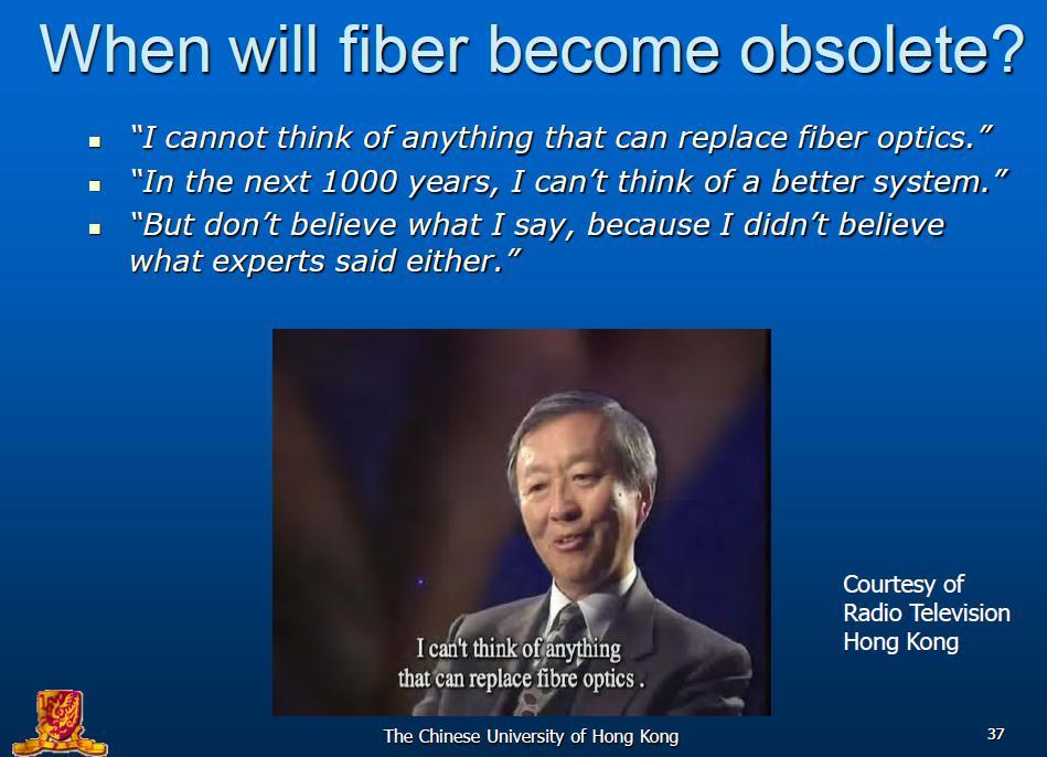
13 The Nobel Prize in Physics 2009 "For ground breaking achievements concerning the transmission of light in fibers for optical communication" "For the invention of an imaging semiconductor circuit the CCD sensor" Charles K. Kao (b Shanghai, China) 1/2 of the prize Standard Telecommunication Laboratories, Harlow, UK; Chinese University of Hong Kong, Hong Kong, China Willard S. Boyle George E. Smith b b /4 of the prize 1/4 of the prize Bell Laboratories, Murray Hill, NJ, USA Kao s Experiment (1966)


")

14 Dr. Narinder S Kapany Born in Moga (Punjab) in October 1926
15 Basic Fiber Optic Link TRANSMITTER RECIEVER DRIVER LIGHT SOURCE OPTICAL FIBER DETECTOR MEDIUM FOR CARRYING LIGHT Converts Electrical signal to light Driver modifies the information into a suitable form for conversion into light (Modulation) Source is LED or ILDs whose output is modulated. Detector accepts light, converts it back to electrical signal. Detector is PIN diode or APD Elect. Signal is demodulated to separate out the information

16 Fiber-Optic System Devices Transmitter (Laser diode or LED). Fiber-Optic Cable (MMF, SMF) Receiver (PIN diode or APDs). Backbone of an OFC System : OPTICAL FIBER acts as transmission channel for carrying light beam loaded with information
 Light propagate by means of Total Internal Reflection")
17 Optical Fiber as Transmission Medium Transmit data as light pulses (first converting electronic signals to light pulses then finally converting back to electronic signals) Light propagate by means of Total Internal Reflection (TIR)
18 Structure of Optical Fiber A dielectric core (doped silica) of high refractive index surrounded by a lower refractive index cladding (SCS, PCS). Basic Structure of a Step-Index Optical Fiber Single mode: 5-10 m Step Index Profile Multimode: 50/62.5 m Graded Index Profile NECESSARY CONDITION FOR TIR: n 1 > n 2

19 Transmission Loss in Optical Glass 1970, First Optical Fiber: Loss 20 db/km at 633nm 1977, losses reduced to 5dB/km at 850nm 1980s, Loss reduced to 0.2 db/km at 1550 nm Dramatic reduction in transmission loss in optical glass Highly pure; Transmitting light through 3 mile thick slab of glass
20 Two Major Communication Issues ATTENUATION (Power loss) Attenuation is signal loss over distance. The light pulses loose their energy and amplitude falls as they travel down the cable. Puts distance limitation on long- haul networks. DISPERSION (Pulse broadening) Dispersion is the broadening of pulse as it travels down. Intermodal (Modal) dispersion Intramodal (Chromatic) dispersion Puts data rate limitation on networks
21 Fiber Attenuation 0.5 db/km at 1310 nm 0.2 db/km at 1550 nm Attenuation in Silica Optical Fibers Limit SNR / distance

22 Fiber Dispersion Dispersion is minimum in SMFs Limit Data Rate
23 Attenuation (db/ km ) Wavelengths of Operation Attenuation in Silica Fibers Optical Windows Wavelength (nm ) 850 nm 1310 nm 1550 nm Both 1310 and 1550 nm are active windows
24 Communication Channel Capacity Communication Medium Carrier Frequency Bandwidth 2 way voice Channels Copper Cable 1 MHz 100 khz < 2000 Coaxial Cable 100 MHz 10 MHz 13,000 Optical Fiber Cables THz 40 THz >3,00,000 or 90,000 Video signals Attenuation in silica OFC 0.2dB/km at 1550nm Pulse Broadening 16 ps/km at 1550 nm


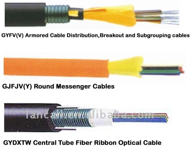

25 Practical Optical Fiber Cable


26 OPTICAL SOURCES LEDs (GaAs, GaAlAs) 850 nm, 1310 nm Low cost easy to use Used for multimode fibers Special edge-emitting LEDs for SMFs Laser Diodes (InGaAsP, InGaAsSb) 850nm, 1310nm, 1550nm Very high power output Very high speed operation Specialized power supply & circuitry Very expensive
 850nm, 1310nm, 1550 nm High sensitivity- operate at very low power levels")
27 OPTICAL DETECTORS PIN Diodes (Si, Ge, InGaAs) 850nm, 1310nm, 1550 nm Low cost APDs (Avalanche Photodiodes, GaAlAs) 850nm, 1310nm, 1550 nm High sensitivity- operate at very low power levels Expensive
28 Advantages of Optical Fiber Wide Bandwidth: Extremely high information carrying capacity (~GHz) 3,00,000 voice channels on a pair of fiber Voice/Data/Video Integrated Service 2.5 Gb/s systems from NTT, Japan; 5 Gb/s System, Siemens Low loss : Information can be sent over a large distance. Losses ~ 0.2 db/km Repeater spacing >100 km with bit rates in Gb/s Interference Free Immune to Electromagnetic interference: No cross talk between fibers Can be used in harsh or noisy environments Higher security : No radiations, Difficult to tap signal Attractive for Defense, Intelligence and Banks Networks
29 Compact & light weight Advantages of Optical Fiber: Contd.. Smaller size : Fiber thinner than human hair Can easily replace 1000 pair copper cable of 10 cm dia. Fiber weighs 28gm/km; considerably lighter than copper Light weight cable Environmemtal Immunity/Greater safety Dielectric- No current, No short circuits Extremely safe for hazardous environments; attractive for oil & petrochemicals Not prone to lightning Wide temperature range Long life > 25 years Abundant Raw Material: Optical fibers made from Silica (Sand) Not a scarce resource in comparison to copper.


 of fibers requires expensive equipment and")

30 Some Practical Disadvantages Optical fibers are relatively expensive. Connectors very expensive: Due to high degree of precision involved Connector installation is time consuming and highly skilled operation Jointing (Splicing) of fibers requires expensive equipment and skilled operators Connector and joints are relatively lossy. Difficult to tap in and out (for bus architectures) - need expensive couplers Relatively careful handling required
31 OFC- Systems Installed Systems: operating at 1310 nm Low loss; minimum pulse broadening Transmission rate 2-10 Gb/s Regeneration of Signal after every km Conversion of O-E-O signal Current OFC Systems: 1550nm wavelength band Silica has lowest loss, increased dispersion Design of Dispersion Shifted Fibers Lowest loss and Negligible dispersion Signal amplification after km Direct amplification of signal in optical domain Erbium Doped Fiber Amplifier (EDFA)

32 EDFA : Fiber Amplifier Erbium Doped Fiber Amplifier Direct amplification of optical signal Flat gain around 1550nm low loss window BW 12,500 GHz ; Enormous potential
33 Increasing Network Capacity Options More Fibers (SDM) Same bit rate, more fibers Slow Time to Market Expensive Engineering Limited Rights of Way Duct Exhaust W D M Same fiber & bit rate, more ls Fiber Compatibility Fiber Capacity Release Fast Time to Market Lower Cost of Ownership Utilizes existing TDM Equipment Faster Electronics (TDM) Higher bit rate, same fiber Electronics more expensive
34 WDM/DWDM OFC- Systems Coincidence of low-loss window & wide-bw EDFA Possibilities of WDM Communication Systems Capable of carrying enormous rates of information Typical WDM network containing various types of optical amplifiers. Examples: 1.1 Tb/s over 150 km ; 55 wavelengths WDM 2.6 Tb/s over 120 km ; 132 wavelengths WDM

35 Fiber Optics Communication Expressway CISCO raising the speed limit LUCENT adding more lanes NORTEL providing faster transport equipments FORESIGHT Lightwave Communication Systems Employing DWDM, EDFA and Soliton pulses ZERO LOSS & NEAR INFINITE BANDWIDTH Provide with a network capable of handling almost all our information needs.

 1.2 Gb/s 1.")
36 Bandwidth 1982 Bandwidth Evolutionary Landmarks TDM (Gb/s) Optical Fiber Fiber is deployed at a rate of 2000 miles every hour Enablers EDFA + Raman Amplifier Dense WDM/Filter High Speed Opto-electronics Advanced Fiber EDFA + Raman Amplifier EDFA All-Optical Network (Terabits Petabits) 40Gb/s 40 Gb/s Mb/s 565 Mb/s 810 Mb/s (1310 nm, 1550 nm) 1.2 Gb/s 1.8 Gb/s 10 Gb/s 2.4 Gb/s TDM DWDM


37 Optical Fiber Platform
38 Bands in Light Spectrum Approximate Attenuation of Single Mode silica fiber cable Visible Infrared nm O Band ~ nm E Band ~ nm S Band ~ nm C Band ~ nm L Band ~ nm


39 All Wave Optical Fiber LUCENT CORNING OFS HUAWEI


40 Photonic Crystal Fibers (PCFs) PCF: around since 1996 (JC Knight et al, OFC (1996) paper PD3 PCFs are optical fibers with a periodic arrangement of low-index material in a background with higher refractive index. The background material is usually undoped silica & the low index is typically provided by air-holes running along their entire length. Solid core PCF Hollow core PCF

41 Important facts regarding PCFs Photonic crystal fibers have a range of properties that can be dramatically different from those of conventional fibers. Index-guiding PCFs can be endlessly single-mode, highly nonlinear and/or have a wide range of dispersion properties Transparency window: UV to mid-ir region Band gap-guiding PCFs can guide light through air or other gases Hollow core PCFs have allowed significant advances in chemical sensing, gas-based non linear optics, high power delivery, pulse compression PCFs can also be the basis for new generation of practical and compact gas-based laser sources and fiber devices etc...
 Videos\SDM NTTT Peta bit system of")
42 Multicore fiber for SDM Pb/s Transmission NTT Japan (2012) Videos\SDM NTTT Peta bit system of future
43 Optical Fibres Beyond Telecom Optical fibres can also have applications in: Fiber Optic Sensing Medicine Light guidance Biological and genetics research Defence/Guidance Industrial materials processing Next generation lasers Optical data processing Transmitting light beyond the near-ir
44 Fiber Optic Sensors An offshoot of fiber optic communication research Realization of high sensitivity of optical fibers to external perturbations (phase modulation, micro bending loss in cabling, modal noise etc) and its exploitation for development of sensors. (An Alternate School of Thought, 1975) High sensitivity of fibers due to long interaction length of light with the physical variable is the attraction. FOS: Any device in which variations in the transmitted power or the rate of transmission of light in optical fiber are the means of measurement or control to measure physical parameters such as strain, pressure, temperature, velocity, and acceleration etc. FOS: A Boon in Disguise
45 Light Wave Parameters 1. Amplitude / Intensity 2. Phase 3. Wavelength 4. Polarization 5. Time / Frequency Variation in any of these parameters due to external influence will form the working principle of the sensor.
46 Supporting Technology Kapron (1970) demonstrated that the attenuation of light in fused silica fiber was low enough that long transmission links were possible Procedure in Fiber optic sensor systems: Transmit light from a light source along an optical fiber to a sensor, which sense only the change of a desired environmental parameter. The sensor modulates the characteristics (intensity, wave length, amplitude, phase) of the light. The modulated light is transmitted from the sensor to the signal processor and converted into a signal that is processed in the control system. The properties of light involved in fiber optic sensors: reflection, refraction, interference and grating
47 Basic Elements of a Fiber Optic Sensor Beam conditioning optics Modulator Light source Transducer Optical Fiber Detector
48 Type of Fiber Optic Sensors Fiber optic sensors can be divided by: Places where sensing happens Extrinsic or Hybrid fiber optic sensors Intrinsic or All-Fiber fiber optic sensors Characteristics of light modulated by environmental effect Intensity-based fiber optic sensors Spectrally-based fiber optic sensors Interferometeric fiber optic sensors
49 ADVANTAGES Immunity to electromagnetic interference (EMI) and radio frequency interference (RFI) All-passive dielectric characteristic: elimination of conductive paths in high-voltage environments Inherent safety and suitability for extreme vibration and explosive environments Tolerant of high temperatures (>1450 o C) and corrosive environments Light weight, and small size High sensitivity

50 What Does F.O.S. Look Like? Various Fiber Optic Sensors
51 GENERAL USES Measurement of physical properties such as strain, pressure, displacement, temperature, velocity, and acceleration in structures of any shape or size Monitoring the physical health of structures in real time (SHM). Damage detection Used in multifunctional structures, in which a combination of smart materials, actuators and sensors work together to produce specific action Any environmental effect that can be conceived of can be converted to an optical signal to be interpreted ; Eric Udd, Fiber Optic Sensors
52 Monitoring in Structural Engineering Buildings and Bridges: concrete monitoring during setting, crack (length, propagation speed) monitoring, prestressing monitoring, spatial displacement measurement, neutral axis evolution, longterm deformation (creep and shrinkage) monitoring, concrete-steel interaction, and post-seismic damage evaluation Tunnels: multipoint optical extensometers, convergence monitoring, shotcrete / prefabricated vaults evaluation, and joints monitoring Damage detection Dams: foundation monitoring, joint expansion monitoring, spatial displacement measurement, leakage monitoring, and distributed temperature monitoring Heritage structures: displacement monitoring, crack opening analysis, post-seismic damage evaluation, restoration monitoring, and old-new interaction


53 General Purpose FOS


54 Fiber Optic Probe Colorimeter Smart Beds Optical fibers in Textiles


55 Fly by Light System-Airframe & Engine


56


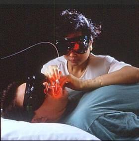

57 MEDICAL APPLICATIONS Small, Flexible Non Toxic Chemically Inert Intrinsically Safe Low Maintenance Ease of Use

58


59 Advantages of Optical Fibers Medical Illumination Products Thin/Small size Flexible Non Toxic Chemically Inert EM Inert No Cross talk Wide Bandwidth Reliable Ease of Use Image Transmission by Fiber Bundle


60 Fibers are Everywhere

61 Fifty Years of Fiber Optics First quarter of the 21 st century will see a continued growth in the demand for fiber optic components.

62
63
64 Bibliography: The excerpts of this lecture are based on the information drawn from following reference. 1. John M. Senior Optical Fiber Communications: Principles and Practice, 2 nd edn., PHI, Gerd Keiser, Optical Fiber Communica tion 3 rd edn., Mc Graw Hill, videos Govind P. Agrawal, Fiber-Optic Communication Systems John Wiley & sons (Asia) Pte Ltd, 3 rd Edn., Bishnu P. Pal, Fundamentals of Fibre Optics in Telecommunication and Sensor Systems, New Age International Publishers, 2005.


65 Questions?


66
Lecture 1: Introduction
 Optical Fibre Communication Systems Lecture 1: Introduction Professor Z Ghassemlooy Electronics & It Division School of Engineering Sheffield Hallam University U.K. www.shu.ac.uk/ocr 1 Contents Reading
Introduction to Fiber Optics
 Introduction to Fiber Optics Dr. Anurag Srivastava Atal Bihari Vajpayee Indian Institute of Information Technology and Manegement, Gwalior Milestones in Electrical Communication 1838 Samuel F.B. Morse
Optical fibre. Principle and applications
 Optical fibre Principle and applications Circa 2500 B.C. Earliest known glass Roman times-glass drawn into fibers Venice Decorative Flowers made of glass fibers 1609-Galileo uses optical telescope 1626-Snell
is a method of transmitting information from one place to another by sending light through an optical fiber. The light forms an electromagnetic
 is a method of transmitting information from one place to another by sending light through an optical fiber. The light forms an electromagnetic carrier wave that is modulated to carry information. The
Optical Fiber Communication
 A Seminar report On Optical Fiber Communication Submitted in partial fulfillment of the requirement for the award of degree Of Mechanical SUBMITTED TO: www.studymafia.org SUBMITTED BY: www.studymafia.org
William Stallings Data and Computer Communications 7 th Edition. Chapter 4 Transmission Media
 William Stallings Data and Computer Communications 7 th Edition Chapter 4 Transmission Media Overview Guided - wire Unguided - wireless Characteristics and quality determined by medium and signal For guided,
SYLLABUS Optical Fiber Communication
 SYLLABUS Optical Fiber Communication Subject Code : IA Marks : 25 No. of Lecture Hrs/Week : 04 Exam Hours : 03 Total no. of Lecture Hrs. : 52 Exam Marks : 100 UNIT - 1 PART - A OVERVIEW OF OPTICAL FIBER
Optical Communications and Networks - Review and Evolution (OPTI 500) Massoud Karbassian
 Massoud Karbassian") Optical Communications and Networks - Review and Evolution (OPTI 500) Massoud Karbassian m.karbassian@arizona.edu Contents Optical Communications: Review Optical Communications and Photonics Why Photonics?
Optical Communications and Networks - Review and Evolution (OPTI 500) Massoud Karbassian m.karbassian@arizona.edu Contents Optical Communications: Review Optical Communications and Photonics Why Photonics?
Optical systems have carrier frequencies of ~100 THz. This corresponds to wavelengths from µm.
 Introduction A communication system transmits information form one place to another. This could be from one building to another or across the ocean(s). Many systems use an EM carrier wave to transmit information.
Performance Evaluation of 32 Channel DWDM System Using Dispersion Compensation Unit at Different Bit Rates
 Performance Evaluation of 32 Channel DWDM System Using Dispersion Compensation Unit at Different Bit Rates Simarpreet Kaur Gill 1, Gurinder Kaur 2 1Mtech Student, ECE Department, Rayat- Bahra University,
OPTICAL NETWORKS. Building Blocks. A. Gençata İTÜ, Dept. Computer Engineering 2005
 OPTICAL NETWORKS Building Blocks A. Gençata İTÜ, Dept. Computer Engineering 2005 Introduction An introduction to WDM devices. optical fiber optical couplers optical receivers optical filters optical amplifiers
COM 46: ADVANCED COMMUNICATIONS jfm 07 FIBER OPTICS
 FIBER OPTICS Fiber optics is a unique transmission medium. It has some unique advantages over conventional communication media, such as copper wire, microwave or coaxial cables. The major advantage is
E2-E3 CONSUMER FIXED ACCESS. CHAPTER-4 OVERVIEW OF OFC NETWORK (Date Of Creation: )
") E2-E3 CONSUMER FIXED ACCESS CHAPTER-4 OVERVIEW OF OFC NETWORK (Date Of Creation: 01-04-2011) Page: 1 Overview Of OFC Network Learning Objective: Optical Fiber concept & types OFC route and optical budget
E2-E3 CONSUMER FIXED ACCESS CHAPTER-4 OVERVIEW OF OFC NETWORK (Date Of Creation: 01-04-2011) Page: 1 Overview Of OFC Network Learning Objective: Optical Fiber concept & types OFC route and optical budget
Ph.D. Course Spring Wireless Communications. Wirebound Communications
 Ph.D. Course Spring 2005 Danyo Danev associate professor Div. Data Transmission, Dept. Electrical Engineering Linköping University SWEDEN Wireless Communications Radio transmissions Mobile telephony Satellite
Data and Computer Communications Chapter 4 Transmission Media
 Data and Computer Communications Chapter 4 Transmission Media Ninth Edition by William Stallings Data and Computer Communications, Ninth Edition by William Stallings, (c) Pearson Education - Prentice Hall,
The absorption of the light may be intrinsic or extrinsic
 Attenuation Fiber Attenuation Types 1- Material Absorption losses 2- Intrinsic Absorption 3- Extrinsic Absorption 4- Scattering losses (Linear and nonlinear) 5- Bending Losses (Micro & Macro) Material
Fiber Optic Communications Communication Systems
 INTRODUCTION TO FIBER-OPTIC COMMUNICATIONS A fiber-optic system is similar to the copper wire system in many respects. The difference is that fiber-optics use light pulses to transmit information down
Absorption: in an OF, the loss of Optical power, resulting from conversion of that power into heat.
 Absorption: in an OF, the loss of Optical power, resulting from conversion of that power into heat. Scattering: The changes in direction of light confined within an OF, occurring due to imperfection in
Elements of Optical Networking
 Bruckner Elements of Optical Networking Basics and practice of optical data communication With 217 Figures, 13 Tables and 93 Exercises Translated by Patricia Joliet VIEWEG+ TEUBNER VII Content Preface
Optical Communications and Networks - Review and Evolution (OPTI 500) Massoud Karbassian
 Massoud Karbassian") Optical Communications and Networks - Review and Evolution (OPTI 500) Massoud Karbassian m.karbassian@arizona.edu Contents Optical Communications: Review Optical Communications and Photonics Why Photonics?
Optical Communications and Networks - Review and Evolution (OPTI 500) Massoud Karbassian m.karbassian@arizona.edu Contents Optical Communications: Review Optical Communications and Photonics Why Photonics?
Comparative Study of an Optical Link with PIN and APD as Photo-Detector Preetam Jain 1, Dr Lochan Jolly 2
 Comparative Study of an Optical Link with PIN and APD as Photo-Detector Preetam Jain 1, Dr Lochan Jolly 2 1 ME EXTC Student Thakur College of Engineering and Technology 2 Professor Thakur College of Engineering
Optical Fiber Enabler of Wireless Devices in the Palms of Your Hands
 Optical Fiber Enabler of Wireless Devices in the Palms of Your Hands A Presentation to EE1001 Class of Electrical Engineering Department at University of Minnesota Duluth By Professor Imran Hayee Smartphone
OFC SYSTEM: Design & Analysis. BC Choudhary, Professor NITTTR, Sector 26, Chandigarh.
 OFC SYSTEM: Design & Analysis BC Choudhary, Professor NITTTR, Sector 26, Chandigarh. OFC point-to-point Link Transmitter Electrical to Optical Conversion Coupler Optical Fiber Coupler Optical to Electrical
Contents for this Presentation. Multi-Service Transport
 Contents for this Presentation SDH/DWDM based Multi-Service Transport Platform by Khurram Shahzad ad Brief Contents Description for this of Presentation the Project Development of a Unified Transport Platform
Class 4 ((Communication and Computer Networks))
)") Class 4 ((Communication and Computer Networks)) Lesson 3... Transmission Media, Part 1 Abstract The successful transmission of data depends principally on two factors: the quality of the signal being transmitted
Class 4 ((Communication and Computer Networks)) Lesson 3... Transmission Media, Part 1 Abstract The successful transmission of data depends principally on two factors: the quality of the signal being transmitted
2. The Basic principle of optical fibre (Or) Working principle of optical fibre (or) Total internal reflection
 Working principle of optical fibre (or) Total internal reflection") Introduction Fibre optics deals with the light propagation through thin glass fibres. Fibre optics plays an important role in the field of communication to transmit voice, television and digital data signals
Introduction Fibre optics deals with the light propagation through thin glass fibres. Fibre optics plays an important role in the field of communication to transmit voice, television and digital data signals
Industrial Automation
 OPTICAL FIBER. SINGLEMODE OR MULTIMODE It is important to understand the differences between singlemode and multimode fiber optics before selecting one or the other at the start of a project. Its different
Chapter 9 GUIDED WAVE OPTICS
 [Reading Assignment, Hecht 5.6] Chapter 9 GUIDED WAVE OPTICS Optical fibers The step index circular waveguide is the most common fiber design for optical communications plastic coating (sheath) core cladding
Optical Amplifiers Photonics and Integrated Optics (ELEC-E3240) Zhipei Sun Photonics Group Department of Micro- and Nanosciences Aalto University
 Zhipei Sun Photonics Group Department of Micro- and Nanosciences Aalto University") Photonics Group Department of Micro- and Nanosciences Aalto University Optical Amplifiers Photonics and Integrated Optics (ELEC-E3240) Zhipei Sun Last Lecture Topics Course introduction Ray optics & optical
Photonics Group Department of Micro- and Nanosciences Aalto University Optical Amplifiers Photonics and Integrated Optics (ELEC-E3240) Zhipei Sun Last Lecture Topics Course introduction Ray optics & optical
Fiber Optic Principles. Oct-09 1
 Fiber Optic Principles Oct-09 1 Fiber Optic Basics Optical fiber Active components Attenuation Power budget Bandwidth Oct-09 2 Reference www.flukenetworks.com/fiber Handbook Fiber Optic Technologies (Vivec
Visible to infrared high-speed WDM transmission over PCF
 Visible to infrared high-speed WDM transmission over PCF Koji Ieda a), Kenji Kurokawa, Katsusuke Tajima, and Kazuhide Nakajima NTT Access Network Service Systems Laboratories, NTT Corporation, 1 7 1 Hanabatake,
OFC SYSTEMS Performance & Simulations. BC Choudhary NITTTR, Sector 26, Chandigarh
 OFC SYSTEMS Performance & Simulations BC Choudhary NITTTR, Sector 26, Chandigarh High Capacity DWDM OFC Link Capacity of carrying enormous rates of information in THz 1.1 Tb/s over 150 km ; 55 wavelengths
Fiberoptic and Waveguide Sensors
 Fiberoptic and Waveguide Sensors Wei-Chih Wang Department of Mecahnical Engineering University of Washington Optical sensors Advantages: -immune from electromagnetic field interference (EMI) - extreme
University of Arizona ECE 430/530: Optical Communication Systems Spring 2010, Ivan B. Djordjevic Introduction to Fiber-Optics Communications
 University of Arizona : Optical Communication Systems Spring 2010, Ivan B. Djordjevic Introduction to Fiber-Optics Communications 1 INTRODUCTION TO FIBER-OPTICS COMMUNICATIONS Optical communication systems
Optical Delay Line Application Note
 1 Optical Delay Line Application Note 1.1 General Optical delay lines system (ODL), incorporates a high performance lasers such as DFBs, optical modulators for high operation frequencies, photodiodes,
2 in the multipath dispersion of the optical fibre. (b) Discuss the merits and drawbacks of cut bouls method of measurement of alternation.
 Discuss the merits and drawbacks of cut bouls method of measurement of alternation.") B.TECH IV Year I Semester (R09) Regular Examinations, November 2012 1 (a) Derive an expression for multiple time difference tt 2 in the multipath dispersion of the optical fibre. (b) Discuss the merits
B.TECH IV Year I Semester (R09) Regular Examinations, November 2012 1 (a) Derive an expression for multiple time difference tt 2 in the multipath dispersion of the optical fibre. (b) Discuss the merits
Photonics and Optical Communication
 Photonics and Optical Communication (Course Number 300352) Spring 2007 Dr. Dietmar Knipp Assistant Professor of Electrical Engineering http://www.faculty.iu-bremen.de/dknipp/ 1 Photonics and Optical Communication
Thursday, April 17, 2008, 6:28:40
 Wavelength Division Multiplexing By: Gurudatha Pai K gurudatha@gmail.com Thursday, April 17, 2008, 6:28:40 Overview Introduction Popular Multiplexing Techniques Optical Networking WDM An Analogy of Multiplexing
DATA TRANSMISSION. ermtiong. ermtiong
 DATA TRANSMISSION Analog Transmission Analog signal transmitted without regard to content May be analog or digital data Attenuated over distance Use amplifiers to boost signal Also amplifies noise DATA
OFC SYSTEM: Design Considerations. BC Choudhary, Professor NITTTR, Sector 26, Chandigarh.
 OFC SYSTEM: Design Considerations BC Choudhary, Professor NITTTR, Sector 26, Chandigarh. OFC point-to-point Link Transmitter Electrical to Optical Conversion Coupler Optical Fiber Coupler Optical to Electrical
Guided Propagation Along the Optical Fiber. Xavier Fernando Ryerson Comm. Lab
 Guided Propagation Along the Optical Fiber Xavier Fernando Ryerson Comm. Lab The Nature of Light Quantum Theory Light consists of small particles (photons) Wave Theory Light travels as a transverse electromagnetic
UNIT-II : SIGNAL DEGRADATION IN OPTICAL FIBERS
 UNIT-II : SIGNAL DEGRADATION IN OPTICAL FIBERS The Signal Transmitting through the fiber is degraded by two mechanisms. i) Attenuation ii) Dispersion Both are important to determine the transmission characteristics
Chapter 4: Transmission Media
 Chapter 4: Transmission Media Page 1 Overview Guided - wire Unguided - wireless Characteristics and quality determined by medium and signal For guided, the medium is more important For unguided, the bandwidth
Guided Propagation Along the Optical Fiber
 Guided Propagation Along the Optical Fiber The Nature of Light Quantum Theory Light consists of small particles (photons) Wave Theory Light travels as a transverse electromagnetic wave Ray Theory Light
Lectureo5 FIBRE OPTICS. Unit-03
 Lectureo5 FIBRE OPTICS Unit-03 INTRODUCTION FUNDAMENTAL IDEAS ABOUT OPTICAL FIBRE Multimode Fibres Multimode Step Index Fibres Multimode Graded Index Fibres INTRODUCTION In communication systems, there
DWDM Theory. ZTE Corporation Transmission Course Team. ZTE University
 DWDM Theory ZTE Corporation Transmission Course Team DWDM Overview Multiplexing Technology WDM TDM SDM What is DWDM? Gas Station High Way Prowl Car Definition l 1 l 2 l N l 1 l 2 l 1 l 2 l N OA l N OMU
Performance Analysis of Designing a Hybrid Optical Amplifier (HOA) for 32 DWDM Channels in L-band by using EDFA and Raman Amplifier
 for 32 DWDM Channels in L-band by using EDFA and Raman Amplifier") Performance Analysis of Designing a Hybrid Optical Amplifier (HOA) for 32 DWDM Channels in L-band by using EDFA and Raman Amplifier Aied K. Mohammed, PhD Department of Electrical Engineering, University
Performance Analysis of Designing a Hybrid Optical Amplifier (HOA) for 32 DWDM Channels in L-band by using EDFA and Raman Amplifier Aied K. Mohammed, PhD Department of Electrical Engineering, University
Optical Fiber. n 2. n 1. θ 2. θ 1. Critical Angle According to Snell s Law
 ECE 271 Week 10 Critical Angle According to Snell s Law n 1 sin θ 1 = n 1 sin θ 2 θ 1 and θ 2 are angle of incidences The angle of incidence is measured with respect to the normal at the refractive boundary
Optical DWDM Networks
 Optical DWDM Networks ain The Oh Columbus, OH 43210 Jain@CIS.Ohio-State.Edu These slides are available at http://www.cis.ohio-state.edu/~jain/cis788-99/ 1 Overview Sparse and Dense WDM Recent WDM Records
Chapter 18: Fiber Optic and Laser Technology
 Chapter 18: Fiber Optic and Laser Technology Chapter 18 Objectives At the conclusion of this chapter, the reader will be able to: Describe the construction of fiber optic cable. Describe the propagation
William Stallings Data and Computer Communications. Bab 4 Media Transmisi
 William Stallings Data and Computer Communications Bab 4 Media Transmisi Overview Guided - wire Unguided - wireless Characteristics and quality determined by medium and signal For guided, the medium is
FIBER OPTICS. Prof. R.K. Shevgaonkar. Department of Electrical Engineering. Indian Institute of Technology, Bombay. Lecture: 26
 FIBER OPTICS Prof. R.K. Shevgaonkar Department of Electrical Engineering Indian Institute of Technology, Bombay Lecture: 26 Wavelength Division Multiplexed (WDM) Systems Fiber Optics, Prof. R.K. Shevgaonkar,
Examination Optoelectronic Communication Technology. April 11, Name: Student ID number: OCT1 1: OCT 2: OCT 3: OCT 4: Total: Grade:
 Examination Optoelectronic Communication Technology April, 26 Name: Student ID number: OCT : OCT 2: OCT 3: OCT 4: Total: Grade: Declaration of Consent I hereby agree to have my exam results published on
UNIT Write notes on broadening of pulse in the fiber dispersion?
 UNIT 3 1. Write notes on broadening of pulse in the fiber dispersion? Ans: The dispersion of the transmitted optical signal causes distortion for both digital and analog transmission along optical fibers.
DEFINITIONS AND FUNDAMENTAL PRINCIPLES IDC
 DEFINITIONS AND FUNDAMENTAL PRINCIPLES Data Communications Information is transmitted between two points in the form of data. Analog» Varying amplitude, phase and frequency Digital» In copper systems represented
Computer Networks Lecture -4- Transmission Media. Dr. Methaq Talib
 Computer Networks Lecture -4- Transmission Media Dr. Methaq Talib Transmission Media A transmission medium can be broadly defined as anything that can carry information from a source to a destination.
Transmission Media. - Bounded/Guided Media - Uubounded/Unguided Media. Bounded Media
 Transmission Media The means through which data is transformed from one place to another is called transmission or communication media. There are two categories of transmission media used in computer communications.
Fiber-Optic Communication Systems
 Fiber-Optic Communication Systems Second Edition GOVIND P. AGRAWAL The Institute of Optics University of Rochester Rochester, NY A WILEY-iNTERSCIENCE PUBLICATION JOHN WILEY & SONS, INC. NEW YORK / CHICHESTER
UNIT-1. Basic signal processing operations in digital communication
 UNIT-1 Lecture-1 Basic signal processing operations in digital communication The three basic elements of every communication systems are Transmitter, Receiver and Channel. The Overall purpose of this system
Module 19 : WDM Components
 Module 19 : WDM Components Lecture : WDM Components - I Part - I Objectives In this lecture you will learn the following WDM Components Optical Couplers Optical Amplifiers Multiplexers (MUX) Insertion
Last Time. Transferring Information. Today (& Tomorrow (& Tmrw)) Application Layer Example Protocols ftp http Performance.
) Application Layer Example Protocols ftp http Performance.") 15-441 Lecture 5 Last Time Physical Layer & Link Layer Basics Copyright Seth Goldstein, 2008 Application Layer Example Protocols ftp http Performance Application Presentation Session Transport Network
15-441 Lecture 5 Last Time Physical Layer & Link Layer Basics Copyright Seth Goldstein, 2008 Application Layer Example Protocols ftp http Performance Application Presentation Session Transport Network
Lecture 5 Transmission. Physical and Datalink Layers: 3 Lectures
 Lecture 5 Transmission Peter Steenkiste School of Computer Science Department of Electrical and Computer Engineering Carnegie Mellon University 15-441 Networking, Spring 2004 http://www.cs.cmu.edu/~prs/15-441
Chapter 8. Digital Links
 Chapter 8 Digital Links Point-to-point Links Link Power Budget Rise-time Budget Power Penalties Dispersions Noise Content Photonic Digital Link Analysis & Design Point-to-Point Link Requirement: - Data
Lecture 5 Transmission
 Lecture 5 Transmission David Andersen Department of Computer Science Carnegie Mellon University 15-441 Networking, Spring 2005 http://www.cs.cmu.edu/~srini/15-441/s05 1 Physical and Datalink Layers: 3
Photonics and Optical Communication Spring 2005
 Photonics and Optical Communication Spring 2005 Final Exam Instructor: Dr. Dietmar Knipp, Assistant Professor of Electrical Engineering Name: Mat. -Nr.: Guidelines: Duration of the Final Exam: 2 hour You
CONTENTS. Chapter 1 Wave Nature of Light 19
 CONTENTS Chapter 1 Wave Nature of Light 19 1.1 Light Waves in a Homogeneous Medium 19 A. Plane Electromagnetic Wave 19 B. Maxwell's Wave Equation and Diverging Waves 22 Example 1.1.1 A diverging laser
Advanced Fibre Testing: Paving the Way for High-Speed Networks. Trevor Nord Application Specialist JDSU (UK) Ltd
 Ltd") Advanced Fibre Testing: Paving the Way for High-Speed Networks Trevor Nord Application Specialist JDSU (UK) Ltd Fibre Review Singlemode Optical Fibre Elements of Loss Fibre Attenuation - Caused by scattering
Advanced Fibre Testing: Paving the Way for High-Speed Networks Trevor Nord Application Specialist JDSU (UK) Ltd Fibre Review Singlemode Optical Fibre Elements of Loss Fibre Attenuation - Caused by scattering
AC : FIBER OPTICS COURSE FOR UNDERGRADUATE ELECTRICAL ENGINEERING STUDENTS
 AC 2009-385: FIBER OPTICS COURSE FOR UNDERGRADUATE ELECTRICAL ENGINEERING STUDENTS Lihong (Heidi) Jiao, Grand Valley State University American Society for Engineering Education, 2009 Page 14.630.1 Fiber
Optical Digital Transmission Systems. Xavier Fernando ADROIT Lab Ryerson University
 Optical Digital Transmission Systems Xavier Fernando ADROIT Lab Ryerson University Overview In this section we cover point-to-point digital transmission link design issues (Ch8): Link power budget calculations
NEW YORK CITY COLLEGE of TECHNOLOGY
 NEW YORK CITY COLLEGE of TECHNOLOGY THE CITY UNIVERSITY OF NEW YORK DEPARTMENT OF ELECTRICAL AND TELECOMMUNICATIONS ENGINEERING TECHNOLOGY Course : Prepared by: TCET 4102 Fiber-optic communications Module
Chapter 3 OPTICAL SOURCES AND DETECTORS
 Chapter 3 OPTICAL SOURCES AND DETECTORS 3. Optical sources and Detectors 3.1 Introduction: The success of light wave communications and optical fiber sensors is due to the result of two technological breakthroughs.
UNIT I INTRODUCTION TO OPTICAL FIBERS
 UNIT I INTRODUCTION TO OPTICAL FIBERS 9 Evolution of fiber optic system Element of an Optical Fiber Transmission link Total internal reflection Acceptance angle Numerical aperture Skew rays Ray Optics
Fiber Optic Communication Link Design
 Fiber Optic Communication Link Design By Michael J. Fujita, S.K. Ramesh, PhD, Russell L. Tatro Abstract The fundamental building blocks of an optical fiber transmission link are the optical source, the
Data and Computer Communications. Tenth Edition by William Stallings
 Data and Computer Communications Tenth Edition by William Stallings Data and Computer Communications, Tenth Edition by William Stallings, (c) Pearson Education - Prentice Hall, 2013 Wireless Transmission
A Survey Report on Fiber Optic Sensors
 A Survey Report on Fiber Optic Sensors G. Alekya Asst.Prof, Department of Physics, Gurunanak Engg College, Ibrahimpatnam, R. R. Dist. Telangana, India ABSTRACT: As the technology changes use of instruments
Chapter-1: Introduction
 Chapter-1: Introduction The purpose of a Communication System is to transport an information bearing signal from a source to a user destination via a communication channel. MODEL OF A COMMUNICATION SYSTEM
Physical Layer Cabling: Fiber-Optic
 Physical Layer Cabling: Fiber-Optic Fiber-Optic Basics The EM Spectrum: Physics and Math Attenuation and Dispersion in Fiber Fiber-Optic Hardware Networking over Fiber-Optic Safety with Fiber Fiber-Optic
Universidade do Algarve Faculdade de Ciências e Tecnologia Departamento de Física Ano lectivo
 Universidade do Algarve Faculdade de Ciências e Tecnologia Departamento de Física Ano lectivo 2016-2017 Unidade Curricular Sistemas de Comunicação Ótica Optical Communication Systems Mestrado Integrado
ECE 435 Network Engineering Lecture 16
 ECE 435 Network Engineering Lecture 16 Vince Weaver http://web.eece.maine.edu/~vweaver vincent.weaver@maine.edu 1 November 2018 Announcements No homework this week. Demo of infiniband / fiber / ethernet
Photonics (OPTI 510R 2017) - Final exam. (May 8, 10:30am-12:30pm, R307)
 - Final exam. (May 8, 10:30am-12:30pm, R307)") Photonics (OPTI 510R 2017) - Final exam (May 8, 10:30am-12:30pm, R307) Problem 1: (30pts) You are tasked with building a high speed fiber communication link between San Francisco and Tokyo (Japan) which
Photonics (OPTI 510R 2017) - Final exam (May 8, 10:30am-12:30pm, R307) Problem 1: (30pts) You are tasked with building a high speed fiber communication link between San Francisco and Tokyo (Japan) which
OPTI510R: Photonics. Khanh Kieu College of Optical Sciences, University of Arizona Meinel building R.626
 OPTI510R: Photonics Khanh Kieu College of Optical Sciences, University of Arizona kkieu@optics.arizona.edu Meinel building R.626 Announcements Homework #4 is due today, HW #5 is assigned (due April 8)
RZ BASED DISPERSION COMPENSATION TECHNIQUE IN DWDM SYSTEM FOR BROADBAND SPECTRUM
 RZ BASED DISPERSION COMPENSATION TECHNIQUE IN DWDM SYSTEM FOR BROADBAND SPECTRUM Prof. Muthumani 1, Mr. Ayyanar 2 1 Professor and HOD, 2 UG Student, Department of Electronics and Communication Engineering,
Lecture 2. Introduction to Optical. Ivan Avrutsky, ECE 5870 Optical Communication Networks, Lecture 2. Slide 1
 Lecture 2 Introduction to Optical Networks Ivan Avrutsky, ECE 5870 Optical Communication Networks, Lecture 2 Slide 1 Optical Communication Networks 1. Why optical? 2. How does it work? 3. How to design
Chapter 12: Optical Amplifiers: Erbium Doped Fiber Amplifiers (EDFAs)
") Chapter 12: Optical Amplifiers: Erbium Doped Fiber Amplifiers (EDFAs) Prof. Dr. Yaocheng SHI ( 时尧成 ) yaocheng@zju.edu.cn http://mypage.zju.edu.cn/yaocheng 1 Traditional Optical Communication System Loss
Chapter 12: Optical Amplifiers: Erbium Doped Fiber Amplifiers (EDFAs) Prof. Dr. Yaocheng SHI ( 时尧成 ) yaocheng@zju.edu.cn http://mypage.zju.edu.cn/yaocheng 1 Traditional Optical Communication System Loss
Module 2. Studoob.in - Where Learning is Entertainment
 Module 2 Module 2 Transmission media - Guided Transmission Media: Twisted pair, Coaxial cable, optical fiber, Wireless Transmission, Terrestrial microwave, Satellite microwave. Wireless Propagation: Ground
Photonics and Fiber Optics
 1 UNIT V Photonics and Fiber Optics Part-A 1. What is laser? LASER is the acronym for Light Amplification by Stimulated Emission of Radiation. The absorption and emission of light by materials has been
Optical Transmission Fundamentals
 Optical Transmission Fundamentals F. Vasey, CERN-EP-ESE Context Technology HEP Specifics 12 Nov 2018 0 Context: Bandwidth Demand Internet traffic is growing at ~Moore s law Global interconnection bandwidth
PROJECT REPORT COUPLING OF LIGHT THROUGH FIBER PHY 564 SUBMITTED BY: GAGANDEEP KAUR ( )
") PROJECT REPORT COUPLING OF LIGHT THROUGH FIBER PHY 564 SUBMITTED BY: GAGANDEEP KAUR (952549116) 1 INTRODUCTION: An optical fiber (or fiber) is a glass or plastic fiber that carries light along its length.
PROJECT REPORT COUPLING OF LIGHT THROUGH FIBER PHY 564 SUBMITTED BY: GAGANDEEP KAUR (952549116) 1 INTRODUCTION: An optical fiber (or fiber) is a glass or plastic fiber that carries light along its length.
Jaringan Komputer. Outline. The Physical Layer
 Jaringan Komputer The Physical Layer Outline Defines the mechanical, electrical, and timing interfaces to the network Theoretical analysis of data transmission Kinds of transmission media Examples: the
Analysis of Dispersion of Single Mode Optical Fiber
 Daffodil International University Institutional Repository Proceedings of NCCIS November 007 007-11-4 Analysis of Dispersion of Single Mode Optical Fiber Hossen, Monir Daffodil International University
Section B Lecture 5 FIBER CHARACTERISTICS
 Section B Lecture 5 FIBER CHARACTERISTICS Material absorption Losses Material absorption is a loss mechanism related to material composition and fabrication process for the fiber. This results in dissipation
INTRODUCTION TO WDM 1.1 WDM THEORY
 1 INTRODUCTION TO WDM 1.1 WDM THEORY Wavelength division muuiplexing (WDM) refers to a muuipiexing and transmission scheme in optical telecommunications fibers where different wavelengths, typically emitted
A Novel Design Technique for 32-Channel DWDM system with Hybrid Amplifier and DCF
 Research Manuscript Title A Novel Design Technique for 32-Channel DWDM system with Hybrid Amplifier and DCF Dr.Punal M.Arabi, Nija.P.S PG Scholar, Professor, Department of ECE, SNS College of Technology,
Project: IEEE P Working Group for Wireless Personal Area Networks N
 July, 2008 Project: IEEE P802.15 Working Group for Wireless Personal Area Networks N (WPANs( WPANs) Submission Title: Millimeter-wave Photonics for High Data Rate Wireless Communication Systems Date Submitted:
Why Using Fiber for transmission
 Why Using Fiber for transmission Why Using Fiber for transmission Optical fibers are widely used in fiber-optic communications, where they permit transmission over long distances and at very high bandwidths.
Introduction. Learning Objectives. On completion of this class you will be able to. 1. Define fiber sensor. 2. List the different types fiber sensors
 Introduction Learning Objectives On completion of this class you will be able to 1. Define fiber sensor 2. List the different types fiber sensors 3. Mech-Zender Fiber optic interferometer Fiber optic sensor
Chirped Bragg Grating Dispersion Compensation in Dense Wavelength Division Multiplexing Optical Long-Haul Networks
 363 Chirped Bragg Grating Dispersion Compensation in Dense Wavelength Division Multiplexing Optical Long-Haul Networks CHAOUI Fahd 3, HAJAJI Anas 1, AGHZOUT Otman 2,4, CHAKKOUR Mounia 3, EL YAKHLOUFI Mounir
CHAPTER ONE INTRODUCTION
 CHAPTER ONE INTRODUCTION 1.1 Background A communication system transmits information from one place to another, whether separated by a few kilometers or by transoceanic distances. Information is often
Transmission Media. Transmission Media 12/14/2016
 Transmission Media in data communications DDE University of Kashmir By Suhail Qadir System Analyst suhailmir@uok.edu.in Transmission Media the transmission medium is the physical path between transmitter
Measuring Photonic, Optoelectronic and Electro optic S parameters using an advanced photonic module
 Measuring Photonic, Optoelectronic and Electro optic S parameters using an advanced photonic module APPLICATION NOTE This application note describes the procedure for electro-optic measurements of both