Signal Integrity for PCB Design
|
|
|
- Jeffery Baldwin
- 6 years ago
- Views:
Transcription
1 Signal Integrity for PCB Design Sep 17, 2014 Lin, Ming Chih
2 Agenda Customizable in Footer Page 2 What does PCB matters for Signal Integrity? Impedance, Loss and Delay of Transmission Line TDR, TDT and S parameters Impulse Response and ISI Signal Integrity Transmission Line Models SI Simulation


3 PCB is a key factor for HSD transmission 5Gbps 10Gbps Customizable in Footer Page 3


4 What characteristics that might degrade SI? PCB Materials Dk and Df Conductivity PCB Layout Stack-up Layout Drills PCB Manufacturing Roughness Etching Customizable in Footer Page 4
5 Agenda Customizable in Footer Page 5 What do PCB matters for Signal integrity? Impedance, Loss and Delay of Transmission Line TDR, TDT and S parameters Impulse Response and ISI Signal Integrity Transmission Line Models SI Simulation

6 Measurement Customizable in Footer Page 6

7 TDR, TDT and S parameters Customizable in Footer Page 7

8 S Parameters Customizable in Footer Page 8
9 Dielectric Loss and Conductor Loss Customizable in Footer Page 9
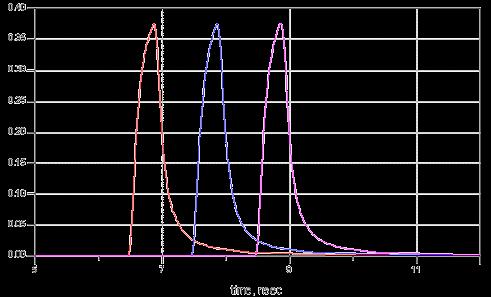
10 Symbol Response in Time and Frequency Domain Customizable in Footer Page 10

")
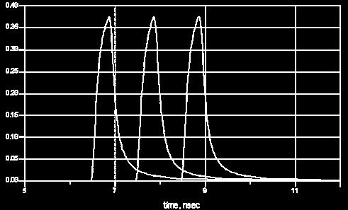
11 Inter Symbol Interference (ISI) Customizable in Footer Page 11


12 Non-ideal transmission lines Customizable in Footer Page 12
13 Open Stub of PTH VIA Customizable in Footer Page 13

14 Open stub leds to high frequency resonance Customizable in Footer Page 14

15 Delata-L proposed by Intel Intel s Delta-L Methodology for Electrical Characterization, Rev Customizable in Footer Page 15
16 Agenda Customizable in Footer Page 16 What do PCB matters for Signal integrity? Impedance, Loss and Delay of Transmission Line TDR, TDT and S parameters Impulse Response and ISI Signal Integrity Transmission Line Models SI Simulation

17 SI Design Flow Modeling Simulation Correlation Analyses Customizable in Footer Page 17


18 Three Types of Channel Modeling Equation Modeling For Pre-simulation Model is equation based Easy to setup Limited structure Optimizable Less accuracy For simple topology EM Modeling Generate S Parameter for Post-Simulation Extracted by EM solver Accurate structure dimension and material parameter are needed EM solver is structure dependent VNA Modeling Generate S Parameter for Post-Simulation Calibration and deembed is necessary Most accurate Full channel can be modeled one time Customizable in Footer Page 18
19 Transmission Line Model based on Formula Customizable in Footer Page 19

20 Ideal Transmission Line Models H E Customizable in Footer Page 20


21 Transmission Line Model based on EM Solvers Customizable in Footer Page 21


22 Channel Simulation EM Solver S Parameter Simplified PCB Routing Customizable in Footer Page 22

23 S Parameters Simulation Insertion Loss Far End Crosstalk Near End Crosstalk Customizable in Footer Page 23


24 Mixed Mode S Parameters Simulation Customizable in Footer Page 24


25 Design Vias TDR Simualtion Customizable in Footer Page 25

26 Discontinuity in Current Path Customizable in Footer Page 26

27 Simulation & Measurement Correlation Simulation Measurement Customizable in Footer Page 27
28 Summary SI is inevitable in all modern electronics system design. PCB design is an important factor for Signal Integrity Simulation is useful for SI designers to check their PCB design in advance. And it can help designers to debug a system. Correlation is important to improve simulation and measurement. Customizable in Footer Page 28
29 Challenges to Obtain Measurement Accuracy and Correlation for PCB Impedance Measurements September 17, 2014 Hidekazu Manabe ( 眞鍋秀一 ) Application Expert Marketing Component Test Division-Kobe Keysight Technologies
30 Agenda PCB Market Overview Challenges to Obtain Measurement Accuracy and Correlation E5063A ENA Series PCB Analyzer Introduction Summary PCB Analyzer Introduction Page 2

")

31 Traditional PCB Measurements test coupon L1/50 trace measurement example Test Coupon Example: 15cm (typ) Test Region (typ 30 to 70% of trace length) Parameters = Impedance (SE & DIFF) Required Tolerance = ±10% PCB Analyzer Introduction Page 3
 and IC packages (6% annual rate).")
32 PCB Market Trends and Forecast PCB market expected to grow at 5% per year from 2012 to Growth drivers are mobile phones (8% annual rate) and IC packages (6% annual rate). PCB Analyzer Introduction Page 4
 and IC package substrates (6% annual rate). PCB Analyzer Introduction Page 5")
33 PCB Market Trends and Forecast by Type Significant growth is expected for flexible PCBs (FPC) (7% annual rate) and IC package substrates (6% annual rate). PCB Analyzer Introduction Page 5
 and double-sided FPC, accounting for nearly 20% in volume (11% annual rate).")
34 FPC Market Forecast FPC market is expected to grow at an average rate of 7% per year. The growth drivers are multilayer FPC, which account for more than 40% in volume (8% annual rate) and double-sided FPC, accounting for nearly 20% in volume (11% annual rate). Production volume is expected to increase for mobile phone, tablet, and mobile electronics applications. Other applications areas expected to have minimal growth. PCB Analyzer Introduction Page 6
35 FPC Types and Applications Single-sided FPC FPC Types Double-sided FPC FPC Applications Camera module LCD module Touch sensor panel Antenna Multi-layer FPC Rigid-Flex Measurement Requirements: FPC trace is measured, rather than coupon. Since trace length is short, higher response resolution is required. Due to increase in data rates, tighter impedance control requirements are increasing. (± 10% => ± 5 ~ 8%). S-parameter required for FPC antenna. VSWR (S11) measured in production. In addition, impedance and isolation (S21) are typically measured in QA. PCB Analyzer Introduction Page 7
36 Agenda PCB Market Overview Challenges to Obtain Measurement Accuracy and Correlation E5063A ENA Series PCB Analyzer Introduction Summary PCB Analyzer Introduction Page 8
37 Problems with TDR Oscilloscopes 1. Inadequate measurement accuracy 2. Measurement results can differ between channels or instruments PCB Analyzer Introduction Page 9

38 Measurement Accuracy Verification Impedance Tolerance +/- 10 % +/- 5% PCB Analyzer Introduction Page 10

39 Measurement Setup TDR Oscilloscope NIST Traceable Standards 50Ω Airline Reference for error compensation Measurement Cables 25Ω Airline Blue Purple Device for measurement result comparison PCB Analyzer Introduction Page 11
40 Measurement Accuracy with TDR Oscilloscopes 1. Offset Error Measurement 2. Device Measurement (25 Ω Airline) PCB Analyzer Introduction Page 12
41 Measurement Setup Channel 1 50 Ω airline PCB Analyzer Introduction Page 13
42 Offset Error Measurement at Channel 1 60 Ω 50 Ω (airline) 51.8 Ω Offset error is +1.8 Ω 40Ω PCB Analyzer Introduction Page 14

43 Offset Error Measurement at Channel 2 60 Ω 50 Ω (airline) 50.2 Ω Offset error is +0.2 Ω 40Ω PCB Analyzer Introduction Page 15
44 Measurement Accuracy with TDR Oscilloscopes 1. Offset Error Measurement 2. Device Measurement (25 Ω Airline) PCB Analyzer Introduction Page 16

45 Measurement Accuracy with TDR Oscilloscopes Considerations for Offset Compensation PCB Analyzer Introduction Page 17
46 Agenda PCB Market Overview Challenges to Obtain Measurement Accuracy and Correlation E5063A ENA Series PCB Analyzer Introduction Summary PCB Analyzer Introduction Page 18
47 What is E5063A ENA Series PCB Analyzer? E5063A ENA Series PCB Analyzer The Best Solution for PCB Manufacturing Test More Accuracy and R&R* More Languages Supported More ESD Robustness also the lowest cost solution in the industry. * Repeatability & Reproducibility PCB Analyzer Introduction Page 19
48 What is E5063A ENA Series PCB Analyzer? PCB Analyzer Introduction Page 20

49 Dedicated GUI for PCB Manufacturing Test Similar look-and-feel to traditional solutions PCB Analyzer Introduction Page 21
 Execute Test Mode Simple and intuitive GUI for non-technical operators Operator recalls test setup file and executes test.")
50 Modes of Operation Edit Test Mode Integrated test file editor allows test engineers to create files with just a few mouse clicks Test engineer determines measurement requirements. Test File (Instrument configuration, test list, limits, etc ) Execute Test Mode Simple and intuitive GUI for non-technical operators Operator recalls test setup file and executes test. PASS / FAIL PCB Analyzer Introduction Page 22


51 Edit Test Mode Intuitive setup flow allows for simple and intuitive operation Setup and Error Correction Wizards Intuitive and error free setup, error correction, and measurements. Dedicated controls for common adjustments The DUT Length Wizard automatically measures the length of the DUT. Test limits can be defined as a percentage of the DUT length. PCB Analyzer Introduction Page 23


52 Execute Test Mode Operator Instructions Customize operator prompts as appropriate for your application. Saving Test Results All test results are displayed on screen in waveform and statistical format for real-time analysis. Results can also be saved to file for later inspection. PCB Analyzer Introduction Page 24


53 More Accuracy and R&R (Repeatability & Reproducibility) (Source: IPC-TM-650 Number 1.9 Measurement Precision Estimation for Variables Data) PCB Analyzer Introduction Page 25
 PCB Analyzer Introduction Page")
54 Accuracy Verification (Measurement Setup) PCB Analyzer Introduction Page 26
 PCB Analyzer Introduction Page 27")
55 Accuracy Verification (Performing Full Calibration) Calibration Wizard Electronic Calibration module (ECal) PCB Analyzer Introduction Page 27

56 Accuracy Verification (Performing Measurements) Channel 1 25 Ω airline PCB Analyzer Introduction Page 28
57 25 Ω Airline after Full Calibration (Channel 1) 25.3 Ω PCB Analyzer Introduction Page 29
 25.")
58 25 Ω Airline after Full Calibration (Channel 2) 25.3 Ω PCB Analyzer Introduction Page 30


59 Measurement Accuracy after Full Calibration Standards of Different Impedance in Series Connection 25 Ω 50 Ω 75 Ω ケーブル Z = 75.2 Ω Z = 50.5 Ω Z = 25.2 Ω PCB Analyzer Introduction Page 31

 The")

60 Accuracy Verification using a NIST Traceable Standard Measurement results are within 0.1 ohm of 25 ohm airline standard. DUT: 25 ohm airline (85052B Verification Kit) The verification kit includes measurement data and uncertainties which are traceable to National Institute of Standards and Technology (NIST). PCB Analyzer Introduction Page 32
 DUT Length = 22 cm Single-ended 50 ohm trace Differential 100 ohm trace Test Conditions 3 operators 7 DUTs 3 measurements on each DUT")
61 R&R Evaluation (Average and Range Method) Single-ended Differential R&R ohm ohm DUT: R&R Evaluation Board (unused ports left open) DUT Length = 22 cm Single-ended 50 ohm trace Differential 100 ohm trace Test Conditions 3 operators 7 DUTs 3 measurements on each DUT Average impedance within 30-70% of the DUT length used for R&R calculations PCB Analyzer Introduction Page 33
62 Why Error Correction? Measure your device, not your measurement system. delay loss DIFF probe USB footswitch SE probe(s) Cables, probes, switches, and fixtures are no longer ideal at today s data rates. To get the most accurate information about the device under test, you must account for errors introduced by your measurement system, such as delay, loss, and mismatch. mismatch PCB Analyzer Introduction Page 34
63 Error Correction Method Comparison Two common types of error correction methods: Deskew Commonly used in time domain instruments Simple to perform Only corrects for delay delay loss mismatch Full calibration (ECal) Commonly used in frequency domain instruments Requires more standards Accounts for all major sources of error delay loss mismatch PCB Analyzer Introduction Page 35
 = 27.9 Ω Deskew Z(avg) = 25.")
64 Accuracy Considerations Same DUT with different test cable lengths, results in very different impedance values. test cable E5063A PCB Analyzer 85053B NIST Traceable 25Ω Airline 150 cm test cable 30 cm test cable Z(avg) = 27.9 Ω Deskew Z(avg) = 25.9 Ω Deskew PCB Analyzer Introduction Page 36
65 Accuracy Considerations Cable loss affects measurement results. E5063A PCB Analyzer test cable Rise Time = 35 ps 150 cm test cable 30 cm test cable Rise Time Insertion Loss Rise Time Insertion Loss Actual rise time:58.5 ps Insertion Loss: -4.4 db Actual rise time:40.6 ps Insertion Loss: -1.9 db PCB Analyzer Introduction Page 37
66 Accuracy Considerations Cable loss is removed by calibration. E5063A PCB Analyzer test cable Rise Time = 35 ps 150 cm test cable 30 cm test cable Rise Time Insertion Loss Rise Time Insertion Loss Actual rise time:35.1 ps Insertion Loss: 0 db Actual rise time:35.1 ps Insertion Loss: 0 db PCB Analyzer Introduction Page 38
67 Accuracy Considerations Error correction is essential to measure the true performance of the device. test cable E5063A PCB Analyzer 85053B NIST Traceable 25Ω Airline 150 cm test cable 30 cm test cable Z(avg) = 25.2 Ω ECal Z(avg) = 25.2 Ω ECal PCB Analyzer Introduction Page 39


68 More Languages Supported An analyzer that speaks your language PCB Analyzer Introduction Page 40

 External ESD protection module (80A02) available, but rise time is degraded.")
69 More ESD Robustness TDR Scopes Difficult to implement protection circuits inside the instrument without sacrificing performance. In addition, protection diodes cannot be placed in front of the sampling bridge as this would limit the bandwidth. This reduces the safe input voltage for a sampling oscilloscope to about 3 V, as compared to 500 V available on other oscilloscopes. Tektronix ApNote XYZ of Oscilloscopes, p17 (02/09, 03W ) External ESD protection module (80A02) available, but rise time is degraded. Rise time degradation from 28ps to 37ps with 80E04 TDR module. Single-channel protection, but only four slots are available. Additional cost of $4K/module. PCB Analyzer Introduction Page 41
.")
70 More ESD Robustness E5063A PCB Analyzer Higher robustness against ESD, because protection circuits are implemented inside the instrument for all ports, while maintaining excellent RF performance. ESD protection circuits inside the instrument To ensure high robustness against ESD, E5063A PCB Analyzer is tested for ESD survival according to IEC801-2 Human Body Model (150 pf, 330Ω). RF Output Center pins tested to 3000 V, 10 cycles. Proprietary ESD protection chip significantly increase ESD robustness, while at the same time maintaining excellent RF performance (24.8 ps rise time for 18 GHz models). PCB Analyzer Introduction Page 42
: E5063A-245 2-port test set, 100 khz to 4.5 GHz E5063A-285 2-port test set, 100 khz to 8.")
71 Configuration E5063A PCB Analyzer = E5063A + Option 011 E5063A => frequency domain Option 011 => time domain and PCB GUI Model/Option Description E5063A ENA Series Network Analyzer Test set options (choose one): E5063A port test set, 100 khz to 4.5 GHz E5063A port test set, 100 khz to 8.5 GHz E5063A-2H5 2-port test set, 100 khz to 18 GHz Software option (mandatory): E5063A-011 Time Domain Analysis / Test Wizard Note: Option 011 is a superset of Option 010. Option 010 is not available separately. PCB Analyzer Introduction Page 43
 USB footswitch U1810B USB Coaxial")
 USB Footswitch USB Barcode Reader (*1) Any TDR passive probe can be used with the PCB")
72 Typical Configuration ENA Mainframe E5063A-245: 100 khz to 4.5 GHz, 2P E5063A-285: 100 khz to 8.5 GHz, 2P E5063A-2H5: 100 khz to 18 GHz, 2P Time Domain / Test Wizard Option (E5063A-011) USB footswitch U1810B USB Coaxial Switch, DC to 18 GHz, SPDT DIFF probe SE probe(s) ECal Module N4431B for E5063A-245/285 N4433A for E5063A-2H5 Third Party Solutions TDR Passive Probes (*1) USB Footswitch USB Barcode Reader (*1) Any TDR passive probe can be used with the PCB Analyzer. PCB Analyzer Introduction Page 44
73 Agenda PCB Market Overview Challenges to Obtain Measurement Accuracy and Correlation E5063A ENA Series PCB Analyzer Introduction Summary PCB Analyzer Introduction Page 45

74 What is E5063A ENA Series PCB Analyzer? E5063A ENA Series PCB Analyzer The Best Solution for PCB Manufacturing Test More Accuracy and R&R* More Languages Supported More ESD Robustness also the lowest cost solution in the industry. * Repeatability & Reproducibility PCB Analyzer Introduction Page 46
75 Summary TDR Oscilloscopes with Offset Compensation Method Users need to make sure measurement devices and measurement standards for compensation have the same impedance value If the above condition is not satisfied, 1. measurement errors cannot be properly compensated resulting measurement inaccuracy 2. measurement results between channels or TDR instruments can differ from each other Keysight E5063A PCB Analyzer Measurement errors can be completely removed with full calibration for 1. accurate measurements 2. measurement correlation between different channels and instruments PCB Analyzer Introduction Page 47
76 PCB Analyzer Introduction Page 48
77 Breakthrough Developments in TDR/TDT Measurement Technology TDR/TDT 信號完整性量測新進展 蔡怡杏 Flory Tsai 台灣是德科技股份有限公司以是為本以德致遠專注量測 75 載
78 Agenda Introduction TDR/TDT and S-parameters Hot TDR Measurements Intel Delta-L Q&A 5 min 15 min 10 min 5 min 5 min 台灣是德科技股份有限公司以是為本以德致遠專注量測 75 載 Page 2

 based TDR/TDT Solutions 台灣是德科技股份有限公司以是為本以德致遠專注量測 75 載 Page")
79 Introduction As data rates increase: Design margins decrease: inter-symbol interference (ISI) increases due to channel/interconnect losses and reflections Trend toward parallel/multi-lane architectures increases crosstalk concerns Characterize signal integrity issues using Scope and Vector Network Analyzer (VNA) based TDR/TDT Solutions 台灣是德科技股份有限公司以是為本以德致遠專注量測 75 載 Page 3
")


 Flexibility Fast to program Compliance Applications")
80 Measurement needs Target applications Demanding Applications for TDR/TDT Measurements SI Lab (PCBs, interconnects, connectors ) Production Test of cables, connectors, interconnects S-Parameter generation for de-embedding Active Device Characterization Research Fast edge and high BW to isolate impedance issues Easy to use. Many channels Low capital cost High accuracy Fast calibration Easy to generate S- parameter files Hot TDR measurements High accuracy (fast step, high BW) Flexibility Fast to program Compliance Applications 台灣是德科技股份有限公司以是為本以德致遠專注量測 75 載 Page 4
 PNA provides the highest performance S-Parameter measurements PNA is the Gold Standard for S-Parameter measurements superior dynamic range vs TDR")
81 VNAs vs TDR Oscilloscopes ENA-TDR is a great solution for <20 GHz Best dynamic range compared to TDR faster acquisition time ESD robustness Ideal for Hot TDR Keysight can address the needs of all your customers (offer both NA and TDR solutions) PNA provides the highest performance S-Parameter measurements PNA is the Gold Standard for S-Parameter measurements superior dynamic range vs TDR (from any vendor) (especially important for low levels of crosstalk, but ultra-low sensitivity is often not required for digital designs) preferred by RF/Microwave engineers Complement each other (not compete). TDR/TDT very intuitive and easy-to-use, preferred by many digital designers useful for quick troubleshooting, fault location analysis measures closer to DC (vs 10 MHz) less expensive than NA having similar BW As a bonus it is a scope too! 台灣是德科技股份有限公司以是為本以德致遠專注量測 75 載 Most SI labs have both solutions. Page 5
82 Agenda Introduction TDR/TDT and S-parameters Hot TDR Measurements Intel Delta-L Q&A 5 min 15 min 10 min 5 min 5 min 台灣是德科技股份有限公司以是為本以德致遠專注量測 75 載 Page 6
 Impedance measurements Locate the")

")


83 Quick Review TDR Time Domain Reflectometry (TDR) Impedance measurements Locate the position and nature of each discontinuity Propagation/Time delay Excess Reactance (Capacitance or Inductance) Effective dielectric constant TDR (Impedance Profile) FFT S-parameters (Return Loss) 1. Reference Plane 2. Connector Launch 3. Uncoupled TX Line 4. Coupled Diff TX Line 5. Connector 6. Open Circuit 台灣是德科技股份有限公司以是為本以德致遠專注量測 75 載 Page 7
 Step Response Propagation/Time delay")
 Far-end crosstalk")
")
84 Quick Review TDT Time Domain Transmission (TDT) Step Response Propagation/Time delay Propagation velocity Rise time degradation Near-end crosstalk (NEXT) Far-end crosstalk (FEXT) Skew FFT TDT (Step Response) S-parameters (Insertion Loss) 台灣是德科技股份有限公司以是為本以德致遠專注量測 75 載 Page 8
85 S-Parameters and TDR/TDT Port 1 Port 2 Port 3 Port 4 Four-port single-ended device Return Loss or TDR Insertion Loss or TDT Near End Crosstalk (NEXT) Far End Crosstalk (FEXT) Frequency Domain Parameters FFT IFFT Time Domain Parameters 台灣是德科技股份有限公司以是為本以德致遠專注量測 75 載 Page 9


86 Together, TDR/TDT and S-Parameters provide tremendous insight TDR Z profile TDT Step Response S11 Return Loss S21 Insertion Loss TDR and S21 are most intuitive, insightful. 台灣是德科技股份有限公司以是為本以德致遠專注量測 75 載 Page 10


87 What TDR edge speed should I use? Edge speed determines two important parameters: 1. TDR Resolution: The faster the edge, the closer two impedance discontinuities can be identified as separate events on the TDR trace. D min = Ɛ = dielectric constant of the transmission system c = speed of light in a vacuum. For Ɛ = 4 and system rise time of 8 ps, D min < 1mm. D D 2. Max S-parameter frequency A step with a fast edge has higher frequency content and enables S- parameter testing to a higher frequency. 台灣是德科技股份有限公司以是為本以德致遠專注量測 75 載 Page 11


88 What TDR edge speed should I use? Select a solution based on your application: Too fast: you ll see impedance discontinuities that will not affect the real signals in your design (you ll waste time fixing things that do not matter) Too slow: discontinuities are masked Choose your TDR edge speed: 1. Full Characterization Rule of Thumb : use TDR edge speeds that are minimum 2x faster than the rise times of your design 2. Compliance Test: use 20%-80% TDR edge speed specified by Standard 500ps 200ps 100ps 25ps 台灣是德科技股份有限公司以是為本以德致遠專注量測 75 載 Page 12

89 TDR Two-Event Resolution (Spatial-Resolution ) To increase the two-event resolution of the TDR system, three items are considered: 1. Increase the speed of the step generator 2. Increase the bandwidth of the oscilloscope 3. Minimize the bandwidth-limiting effects of the test system - minimize use of adapters, cabling - use good quality fixturing - compensate for losses using TDR calibration (de-embedding) 台灣是德科技股份有限公司以是為本以德致遠專注量測 75 載 Page 13
 50 GHz, yields highest TDR resolution. Single-ended and Differential Device Testing (True-Mode Stimulus) N1055 A Options: N1055A Bandwidth 35 GHz (2.")
90 86100D DCA-X with N1055A 35/50 GHz TDR/TDT Modules A fully integrated TDR/TDT/S-parameter measurement system that provides calibrated impedance and S- parameter analysis on up to 16 channels in real-time. Fastest TDR Edge Speed Up to 8 ps (typ) 50 GHz, yields highest TDR resolution. Single-ended and Differential Device Testing (True-Mode Stimulus) N1055 A Options: N1055A Bandwidth 35 GHz (2.92mm)* 50 GHz (1.85mm) N1055A Channel Count 2 Channels per module* 4 channels per module N1055A Connector Type Male Female * upgradeable Calibrated impedance and S-parameter results displayed in real-time Electronic Calibration (ECal) DC-67 GHz module support Calibration Made Easy using ECal modules or mechanical SOLT standards. Built-in Electrostatic Discharge (ESD) Protection Adjustable TDR Edge Speed 台灣是德科技股份有限公司以是為本以德致遠專注量測 75 載 Ultra-thin remote heads - minimize adapters/cables Highest Channel Count - Up to 16 channels per mainframe. High-Bandwidth Oscilloscope N1055A operates in receiver-only mode. Page 14


91 86100D DCA-X with N1055A 35/50 GHz TDR/TDT Modules Performance & Accuracy: Compare the Steps: Keysight Raw Step, risetime = 9.5 ps Keysight Calibrated Step, risetime = 8.4 ps Keysight Calibrated Step, risetime = 11.6 ps 台灣是德科技股份有限公司以是為本以德致遠專注量測 75 載 Page 15


92 TDR Resolution < 1mm 25 GHz Bandpass Filter 1 Impedance Profile 3 Zoom mm S-parameters All features visible! TDR resolution < 1mm Point 3 = taper Points 4, 5, 6 = 3 capacitors spaced by < 1mm 台灣是德科技股份有限公司以是為本以德致遠專注量測 75 載 Bandpass Filter Page 16

93 86100D DCA-X New Software FlexDCA Demo 台灣是德科技股份有限公司以是為本以德致遠專注量測 75 載 Page 17
94 Agenda Introduction TDR/TDT and S-parameters Hot TDR Measurements Intel Delta-L Q&A 5 min 15 min 10 min 5 min 5 min 台灣是德科技股份有限公司以是為本以德致遠專注量測 75 載 Page 18
95 db ohm Why Measure Hot TDR? Hot TDR measurement is the impedance analysis of active devices under actual operation conditions. Typically, impedance of the device in the OFF state and ON state (Hot TDR) is significantly different. Impedance may vary with the data rate as well. TDR(Time Domain) OFF Return Loss (Freq Domain) 1333Mbps (active) 334Mbps (active) 台灣是德科技股份有限公司以是為本以德致遠專注量測 75 載 1G 2G 3G 4G 5G 6G 666M freq(hz) Page 19
96 Multiple Reflections 1. Signal transmitted from Tx Eye Degradation Tx Channel Rx 3. Re-reflection from Tx due to impedance mismatches... 台灣是德科技股份有限公司以是為本以德致遠專注量測 75 載 2. Partial reflection from Rx due to impedance mismatches Page 20

97 Source Termination Effects Source Impedance NOT Matched Source Impedance Matched 台灣是德科技股份有限公司以是為本以德致遠專注量測 75 載 Page 21

98 Many Standards Require Hot TDR Measurements 台灣是德科技股份有限公司以是為本以德致遠專注量測 75 載 Page 22
99 Serial ATA Return Loss and Impedance Balance Transmitters (Tx): When measuring output impedance of transmitters the operating condition shall be during transmission of MFTP. This is to assure the measurement is performed during a mode of operation that represents normal operation. MFTP from Tx Measurement Challenge How to avoid effects of the transmitter signal on measurements? 台灣是德科技股份有限公司以是為本以德致遠專注量測 75 載 Page 23
100 Minimizing Errors from the Transmitter Signal TDR Scopes VNA Tx t t wideband receiver captures all of the signal energy from the transmitter t Tx t t narrowband receiver minimizes the effects of the data signal from the transmitter t fc freq fc freq time Extensive averaging is necessary to obtain a stable waveform. 台灣是德科技股份有限公司以是為本以德致遠專注量測 75 載 time In many cases, averaging is not necessary to obtain a stable waveform. Page 24
 Return Loss (Freq Domain)")

101 Avoid Spurious Feature TDR(Time Domain) Return Loss (Freq Domain) Fluctuations due to Tx signal Spurs due to Tx signal 台灣是德科技股份有限公司以是為本以德致遠專注量測 75 載 Page 25
 Return Loss")


102 Avoid Spurious Feature TDR(Time Domain) Return Loss (Freq Domain) 1-click Operation From the data rate (user input), spurious frequencies are determined and automatically avoided during the sweep. 台灣是德科技股份有限公司以是為本以德致遠專注量測 75 載 Page 26


103 What is ENA Option TDR? The ENA Option TDR is an application software embedded on the ENA, which provides an one-box solution for high speed serial interconnect analysis. Time Domain Frequency Domain 3 Breakthroughs for Signal Integrity Design and Verification Eye Diagram Simple and Intuitive Operation Fast and Accurate Measurements ESD protection inside High ESD Robustness 台灣是德科技股份有限公司以是為本以德致遠專注量測 75 載 Page 27


104 Summary of Hot TDR Multiple reflections due to impedance mismatches significantly impact signal integrity. Typically, impedance of the device in the OFF state and ON state (Hot TDR) is significantly different. Impedance may vary with the data rate as well. Therefore it is essential to characterize the device under actual operating conditions. 台灣是德科技股份有限公司以是為本以德致遠專注量測 75 載 Page 28
105 Agenda Introduction TDR/TDT and S-parameters Hot TDR Measurements Intel Delta-L Q&A 5 min 15 min 10 min 5 min 5 min 台灣是德科技股份有限公司以是為本以德致遠專注量測 75 載 Page 29


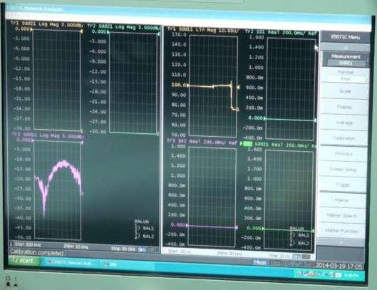
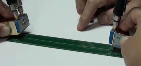
106 Intel Delta-L A new VNA-based solution to effectively move the Via effect for PCB diff. trace insertion loss characterization Issue & Methodology How to De-embedding the Via? Total Solution ❶ 4-port E5071C ❷ Intel Test Coupon Delta-L Loss Characterization ❸ Probes & S/W Intel Web: Video On-line: 台灣是德科技股份有限公司以是為本以德致遠專注量測 75 載 Page 30
107 台灣是德科技股份有限公司以是為本以德致遠專注量測 75 載 Page 31
108 High-Frequency Material Measurement Techniques Sep. 17, 2014 Kenny Liao 廖康佑資深專案經理是德科技 Confidential 1

109 Agenda Page 2 What are we measuring What are the applications What are our solutions PCB Materials Test
110 Permittivity and Permeability Definitions Permittivity (Dielectric Constant) Permeability 0 r interaction of a material in the presence of an external electric field. ' r j " r 0 ' " r j r interaction of a material in the presence of an external magnetic field. Dk Page
111 Electromagnetic Field Interaction Electric Fields STORAGE LOSS Magnetic Fields Permittivity MUT Permeability r ' r j " r STORAGE r ' r j " r LOSS Page
112 Loss Tangent tan " r ' r '' r r ' r tan D 1 Q Energy Lost per Cycle Energy Stored per Cycle Df D Dissipation Factor Q Quality Factor Page
113 Relaxation Constant t t = Time required for 1/e of an aligned system to return to equilibrium or random state, in seconds. 100 ' r Water at 20 o C 10 t c f c " r 1 1 most energy is lost at 1/t f, GHz Debye equation : ( ) s 1 j t Page
114 Applications for Materials Measurement Industry Electronics Aerospace/Defense Industrial materials Food & Agriculture Forestry & Mining Pharmaceutical & Medical Applications / Products Capacitor, substrates, PCB, antenna, ferrites, magnetic recording heads, absorbers, SAR phantom materials, sensor Stealth, RAM (Radiation Absorbing Materials), radomes Ceramics and composites: IC package, aerospace and automotive components, cement, coatings, bio-implants Polymers and plastics: fibers, substrates, films, insulation materials Hydrogel: disposable diaper, soft contact lens Liquid crystal: displays Rubber, semiconductors and superconductors Other products containing these materials: tires, paint, adhesives, etc. Food preservation (spoilage) research, food development for microwave, packaging, moisture measurements Moisture measurements in wood or paper, oil content analysis Drug research and manufacturing, bio-implants, human tissue characterization, biomass, chemical concentration, fermentation Page 7
, radomes Ceramics and composites: IC package,")
115 Applications for Materials Measurement Industry Electronics Aerospace/Defense Industrial materials Food & Agriculture Forestry & Mining Pharmaceutical & Medical Applications / Products Capacitor, substrates, PCB, antenna, ferrites, magnetic recording heads, absorbers, SAR phantom materials, sensor Stealth, RAM (Radiation Absorbing Materials), radomes Ceramics and composites: IC package, aerospace and automotive components, cement, coatings, bio-implants Polymers and plastics: fibers, substrates, films, insulation materials Hydrogel: disposable diaper, soft contact lens Liquid crystal: displays Rubber, semiconductors and superconductors Other products containing these materials: tires, paint, adhesives, etc. Food preservation (spoilage) research, food development for microwave, packaging, moisture measurements Moisture measurements in wood or paper, oil content analysis Drug research and manufacturing, bio-implants, human tissue characterization, biomass, chemical concentration, fermentation Page 8
116 Probe Kit / Fixture Portfolio Material types Materials measurement software 85071E Liquid 16452A Gel Liquid test fixture 85070E Dielectric probe Semi-solids (Powder) Solid Substrate Toroidal core 16453A 16451B Dielectric test fixture 16454A 85072A 85071E-Exx Split post dielectric resonators (SPDR) Magnetic material test fixture 10 GHz split cylinder resonator DC 1 khz 1 MHz 1 GHz 10 GHz 20 GHz 50 GHz 100 GHz Frequency Page 9
117 Lots of methods. Which is Best? It Depends on: Frequency of interest Form of material (i.e., liquid, powder, solid, sheet) Expected value of ε r and μ r Required measurement accuracy Material properties (i.e., homogeneous, isotropic) Sample size restrictions Destructive or non-destructive Contacting or non-contacting Temperature Page

118 LCR and Impedance Analyzer Solutions High Loss Liquid 16452A Liquid Fixture (Parallel Plate) 85070E Dielectric Probe Kit Solid 16454A Magnetic Test Fixture Low Loss 16451B Parallel Plate 16453A Parallel Plate 1KHz 1 MHz 10 MHz 1Ghz 3 Ghz Page

119 Parallel Plate Solutions Page E4990A 16451B E4991B with option A 16452A Liquid Test Fixture

120 Inductance Solutions Page
121 Network Analyzer Solutions High Loss Liquid 85070E Dielectric Probe Kit 85071E Transmission Line Solid 85071E-100 Free Space Low Loss 85071E-300 Resonant Cavity Open Resonator (KeyCom) 200MHz --1 GHz 20GHz 50Ghz 110GHz 1.1 THz Page
122 Coaxial Probe System Computer (Optional for PNA or ENA) Network Analyzer (or E4991A Impedance Analyzer) GP-IB, LAN or USB 85070E Software (included in kit) 85070E Dielectric Probe Calibration is required Page
 non-magnetic isotropic homogeneous no air gaps or")
123 Coaxial Probe Material assumptions: effectively infinite thickness Page Reflection (S 11 ) non-magnetic isotropic homogeneous no air gaps or bubbles r
 Withstands -40 to 200 degrees C Flanged")


124 Three Probe Designs High Temperature Probe GHz (low end 0.01GHz with impedance analyzer) Withstands -40 to 200 degrees C Flanged design allows measuring flat surfaced solids Slim Form Probe GHz Low cost consumable design Fits in tight spaces, smaller sample sizes For liquids and soft semisolids only Performance Probe GHz Withstands -40 to 200 degrees C Hermetically sealed on both ends, OK for autoclave Food grade stainless steel Page

125 Coaxial Probe Example Data Page
126 Coaxial Probe Example Data Page

127 Coaxial Probe Example Data Page


128 Pred Cal Martini Meter! real 98.5 real 99.5 real 99.0 real real real 97.1 real 96.6 real real real 95.2 real 90.9 real real real real Measured Y Infometrix, Inc. 5 Page
129 Transmission Line System Computer (Optional for PNA or ENA) Network Analyzer GP-IB, LAN or USB 85071E Materials Measurement Software Calibration is required Sample holder connected between coax cables Page


130 Transmission Line Sample Holders Coaxial Waveguide Page
 11 Transmission (S ) 21 r and")
131 Transmission Line Material assumptions: sample fills fixture cross section Page l no air gaps at fixture walls flat faces, perpendicular to long axis Known thickness > 20/360 λ Reflection (S ) 11 Transmission (S ) 21 r and r
132 Transmission Example Data Page
133 Transmission Example Data Page
134 Transmission models in the 85071E Software Algorithm Measured S-parameters Output Nicolson-Ross S11, S21, S12, S22 ε r and μ r NIST Precision S11, S21, S22 ε r Fast Transmission S21, S12 ε r Poly Fit 1 S11, S21, S12, S22 ε r and μ r Poly Fit 2 S12, S21 ε r Stack Two S21, S12 (2 samples) ε r and μ r Page
135 Reflection models in the 85071E Software Algorithm Measured S-parameters Output Short Backed S11 ε r Arbitrary Backed S11 ε r Single Double Thickness S11 (2 samples) ε r and μ r Page
136 Transmission Free-Space System Computer (Optional for PNA or ENA) Network Analyzer GP-IB, LAN or USB 85071E Materials Measurement Software Calibration is required Sample holder fixtured between two antennae Page
137 Non-Contacting method for High or Low Temperature Tests. Free Space with Furnace Page
138 Transmission Free-Space Material assumptions: Flat parallel faced samples Sample in non-reactive region l Beam spot is contained in sample Known thickness > 20/360 λ Reflection (S11 ) Transmission (S21 ) r and r Page
139 Free Space Example Data Page

140 Free Space Example Data Page
141 Resonant Cavity System Computer (Optional for PNA or ENA) Network Analyzer GP-IB or LAN Resonant Cavity Software No calibration required Resonant Cavity with sample connected between ports. Page


142 Resonant Cavity Fixtures Agilent Split Cylinder Resonator IPC TM ASTM 2520 Waveguide Resonators Split Post Dielectric Resonators from QWED Page
143 Resonant Cavity Technique fc = Resonant Frequency of Empty Cavity fs = Resonant Frequency of Filled Cavity empty cavity Q c Qc = Q of Empty Cavity Qs = Q of Filled Cavity Vs = Volume of Empty Cavity Vc = Volume of Sample S21 r r 1 Vc 4V s V c fc 2V 1 Q s ASTM 2520 s f f f c s f s 1 Q c Page
144 Resonant Cavity Technique r r 1 Vc 4V s V c fc 2V 1 Q s s empty cavity fc = Resonant Frequency of Empty Cavity sample inserted fs = Resonant Frequency of Filled Cavity Q s Q c Qc = Q of Empty Cavity S21 Qs = Q of Filled Cavity f s f c f Vs = Volume of Empty Cavity Vc = Volume of Sample f ASTM 2520 s f s 1 Q c Page
145 Resonant Cavity Technique r r 1 Vc 4V s V c fc 2V 1 Q empty cavity fc = Resonant Frequency of Empty Cavity sample inserted fs = Resonant Frequency of Filled Cavity Q s Q c Qc = Q of Empty Cavity S21 Qs = Q of Filled Cavity f s f c f Vs = Volume of Empty Cavity Vc = Volume of Sample s ASTM 2520 s f s f s 1 Q c Page

146 Resonant Cavity Example Data Page
147 Resonant vs. Broadband Transmission Methods Low Loss materials Thin Films and Sheets Resonant Yes e r resolution 10-4 Yes 10GHz sample thickness <1mm Broadband No e r resolution 10-2 No 10GHz optimum thickness ~ 5-10mm Calibration Required No Yes Measurement Frequency Coverage Single Frequency Broadband or Banded Page


148 Microwave Materials Measurement Products Model Number Description 85070E Dielectric Probe Kit High Temperature Probe Slim Form Probe Performance Probe Advanced Functionality 85071E Materials Measurement Software Free Space Calibration Arch Reflectivity Software Resonant Cavity Software Advanced Functionality 85072A 10GHz Split Cylinder Resonant Cavity Page


149 Materials Ordering Convenience Specials Model Number Description 85071E E19 E03 E04 E15 E07 Split Post Dielectric Resonators from QWED 1.1GHz 2.5GHz 5GHz 15GHz 22GHz 85071E E02 E01 E22 E18 E24 Quasi-optical products from Thomas Keating Ltd GHz Quasi-optical Table GHz Quasi-optical Table GHz Additional set of horns for above tables GHz Additional set of horns for above tables GHz Additional set of horns for above tables Page

150 Summary of methods Page
151 Resources Websites Materials Test Equipment webpsite Application notes Basics of Measuring the Dielectric Properties of Materials ( EN, Aug 2013) Solutions for Measuring Permittivity and Permeability with LCR Meters and Impedance Analyzers ( EN, Sep 2013) Split Post Dielectric Resonators for Dielectric Measurements of Substrates ( EN, Jul 2006) Tech overviews, brochures and selection guides Measuring Dielectric Properties using Agilent s Materials Measurement Solutions - Brochure ( EN, Apr 2013) Choosing the Optimal Method for Testing Dielectric Properties of Materials - Application brief ( EN, Jun 2013) 85070E Dielectric Probe Kit ( EN, Jun 2012) 85071E Materials Measurement Software ( EN, Jun 2012) 85072A 10-GHz Split Cylinder Resonator ( EN, May 2012) LCR Meters, Impedance Analyzers and Test Fixtures Selection Guide ( E, Apr 2012) Videos PNA Demo videos > Materials Measurements YouTube (external Agilent) 85070E dielectric probe with FieldFox (2009) 85072A 10 GHz Split Cylinder Resonator (2009) Customer viewable training slides Microwave Dielectric Spectroscopy Workshop (2004) Free Space Materials Measurement Seminar (Jun 2005) 44 Page
152 PCB Materials Test
153 Available Measurement Methods PCB Dk/Df Characterization Methods Parallel plate Transmission line Resonant cavity Typical frequency range Up to 1 GHz 100 MHz to 110 GHz 1 GHz to 40 GHz Parallel plate Transmission line Resonant cavity Dk: Dielectric constant (Relative permittivity) Df: Dissipation factor (Loss tangent) Page 46


 Enable to measure multi-layer PCB SPDR: Split Post Dielectric")
154 Resonant Cavity Method with SPDR Fixture ENA/PNA Network Analyzer with Materials Measurement Software E5063A SPDR fixture Sample Key Features Superior accuracy to measure lower loss materials Convenient and fast measurement of substrates, PCB and thin films Non-destructive and noncontacting measurement (Just insert your MUT into the slit of the fixture) Enable to measure multi-layer PCB SPDR: Split Post Dielectric Resonator (SPDR supplier: QWED) Page 47
155 Cross-Section of SPDR fixture Sample l Dielectric Resonator Dielectric Resonator h h G Coupling Loop z Metal Enclosure SPDR Performance (QWED) Nominal freq. of the basic line of SPDRs: 1.1/1.9/2.45/3.2/5/10/15 GHz (Customization is possible) Uncertainty of the real permittivity (typical): ±1 % (Providing that the average thickness of MUT is measured with accuracy ±0.7 % or better; Δε/ε = ±(0.15+Δh/h) %) Uncertainty of tan δ (typical): ±3 % Resolution of tan δ: 2 x 10⁻⁵ Operational temperature range: -200 ~ +110 Page 48
156 Parallel Plate Method Permittivity Evaluation E4990A E4991B with option A 16451B 16451B LF/HF Solution (20 Hz to 30 MHz) RF Solution (1 MHz to 1 GHz) Page 49
157 Appendix Page 50
 Page 51")
158 SPDR (for 10 GHz) Page 51

159 SPDR (Split Post Dielectric Resonator) SPDR Resonators for different frequencies Page 52
160 Page Cp G Equivalent Circuit Thickness = t Electrodes (Area=A) Co : Air Capacitance C G j C C C j C j G Y p p 0 0 * C G j C C p r.tan 0 0 r r p r A G t A C t Parallel Plate Method 53


")

161 Materials Measurement Methods 85070E 16454A Inductance Coaxial Probe 16451B/53A Parallel Plate (Capacitance) Resonant Cavity Transmission Line Free Space 85072A Page 54


162 Thank You Confidential 55
163 References R N Clarke (Ed.), A Guide to the Characterisation of Dielectric Materials at RF and Microwave Frequencies, Published by The Institute of Measurement & Control (UK) & NPL, 2003 J. Baker-Jarvis, M.D. Janezic, R.F. Riddle, R.T. Johnk, P. Kabos, C. Holloway, R.G. Geyer, C.A. Grosvenor, Measuring the Permittivity and Permeability of Lossy Materials: Solids, Liquids, Metals, Building Materials, and Negative-Index Materials, NIST Technical Note Test methods for complex permittivity (Dielectric Constant) of solid electrical insulating materials at microwave frequencies and temperatures to 1650, ASTM Standard D2520, American Society for Testing and Materials Janezic M. and Baker-Jarvis J., Full-wave Analysis of a Split-Cylinder Resonator for Nondestructive Permittivity Measurements, IEEE Transactions on Microwave Theory and Techniques vol. 47, no. 10, Oct 1999, pg J. Krupka, A.P. Gregory, O.C. Rochard, R.N. Clarke, B. Riddle, J. Baker-Jarvis, Uncertainty of Complex Permittivity Measurement by Split-Post Dielectric Resonator Techniques, Journal of the European Ceramic Society No. 10, 2001, pg Basics of Measureing the Dielectric Properties of Materials. Agilent application note EN AM. Nicolson and G. F. Ross, "Measurement of the intrinsic properties of materials by time domain techniques," IEEE Trans. Instrum. Meas., IM-19(4), pp , Improved Technique for Determining Complex Permittivity with the Transmission/Reflection Method, James Baker-Jarvis et al, IEEE transactions on microwave Theory and Techniques vol 38, No. 8 August 1990 P. G. Bartley, and S. B. Begley, A New Technique for the Determination of the Complex Permittivity and Permeability of Materials Proc. IEEE Instrument Meas. Technol. Conf., pp , Page
 Leo Lee ( 李文福 ) By")
164 LiTek s PCB Delta-L Measurement Solution Presented by 厘科科技 (LiTek Technologies) Leo Lee ( 李文福 ) By 2014
. Suitable for any layers in the PCB.")
165 Background of PCB Delta-L Measurement. Triggered by Intel. Remove the via effect that not included in our measurement. Use a easy way to implement (Delta of Loss). Suitable for any layers in the PCB. Real Differential Loss Measurement Page 2
166 Page 3
167 Page 4
")
168 LiTek s PCB Delta-L Solution E5071C, 20G TpNA software LiTek s PCB Probe Agilent E-Cal PCB (DUT) Page 5

169 Guide Pin Information Page 6
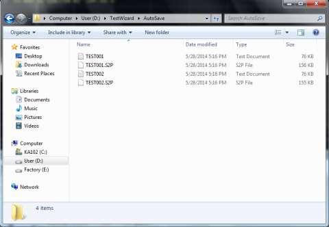
170 Why TpNA for PCB Delta-L Measurement? A PC based GUI Software, friendly control interface. Help to finish all steps including: >>Perform E-Cal >>Setup all features for SDD21 measurement (optional including Time- Domain Differential Impedance) >>Recording all layers, Reference and Longer Length PCB s insertion loss in the TpNA. >>Auto Calculating Delta-L result in the TpNA >>Easily export a result by just one button press Who can finish these jobs One who can use a PC and without the knowledge to use ENA. Page 7


171 How to do the measurement 當 TpNA 開啟後, 建立一個 PCB for Delta-L 的專案. 使用者將 E-Cal 分別與 ENA 的 4 個埠連接後, 按下 TpNA 的 執行 E-Cal 按鈕,TpNA 就會完成所有的 E-Cal 校正 Page 8

172 How to do the measurement Page 9

173 How to do the measurement Page 10

174 How to do the measurement 當 Reference Length 及 DUT Length 的 Insertion Loss 量測完畢,TpNA 就會自動的計算 Delta-L Page 11


175 How to do the measurement 在報表頁中, 使用者按下 輸出報表 的按鈕,TpNA 就會完成一份 Excel 格式的報表 Page 12
176 E5063A Application 1
177 Agenda E5063A Introduction Option 011(Start up Time Domain) Option PIC TDR /SET2DIL Software 2

178 外觀介紹 LCD 觸碰瑩幕 硬體按鍵 USB 接孔 測試孔 (N-Type) 設備電源開關 接地端口 瑩幕輸入孔 USB488 外部控制 SSD GPIB 24 Bit I/O Port 外部觸發輸入端子 參考訊號端子 USB 接孔網路接孔 設備電源開關 設備電源接孔 設備序號標籤 設備校正標籤 3
179 Agenda E5063A Introduction Option 011(Start up Time Domain) Option PIC TDR /SET2DIL Software 4
180 Main Frame 支持五國語言 : 英文 繁體中文 簡體中文 韓文 日文 5

181 Prepared to Start 開始設定 6

182 步驟一, 儀器組態設定 點選進階模式 7
183 步驟一, 儀器組態設定 外接二個 U1810B, 故選擇此項 選擇單端與差分量測 8

184 步驟二, 誤差校正 Port1 &2 ; Port3 皆選擇 Deskew 校正並按下執行按鈕進行校正程序 Open Thru Load Load Thru Open 9

185 步驟三, 測試流程設定 10

186 步驟四, 測試清單列表 步驟 1: 可無限制增加量測的參數 步驟 2: 選擇編輯的項目 步驟 3: 點選 編輯 來進行細項的設定, 記得每一組項目都需執行編輯中的測試待測物長度 11


187 步驟五, 編輯量測 開路定義 : 差分線長測試 開路定義 : 單動線長測試 12

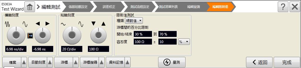
188 步驟六, 編輯限制值 13

189 步驟七, 開始量測及結果儲存 14
190 Agenda E5063A Introduction Option 011(Start up Time Domain) Option PIC TDR /SET2DIL Software 15
191 步驟一, 儀器組態設定 由外部控制 ( 儀測軟件 ) 控制 選擇差分量測 16

192 步驟二, 誤差校正 選擇 Deskew 與振幅 ; 損失校正 並按下執行按鈕進行校正程序 Open Thru Load 17

193 步驟三, 開啟儀測 TDR 軟件 1. 點選桌面 TDR 的軟件 2. 執行 TDR Automation Test 程式 18
194 步驟三, 開啟儀測 TDR 軟件 19


195 功能說明 -File 刪除量測資料 20
 選擇測量的功能 ( 阻抗 / 損失 ) 查看軟件資訊")
196 功能說明 -System 選擇軟體的語系 ( 中 / 英文 ) 選擇測量的功能 ( 阻抗 / 損失 ) 查看軟件資訊 21
 5. 設定板材 ( 目前並無使用 ) 6. 設定量測結果的判定依據 ( 多數以平均值為標準 ) 2. 設定量測儲存資訊 5. 設定板材 6.")
197 功能說明 - 測試參數 1. 設定產品資訊 3. 設定單分 / 差動測試 4. 設定量測的誤差值 設定說明 : 1. 設定產品量測資料, 以便於產生報告時可以使用 2. 設定量測存資訊, 可在量測時同步記錄曲線資料及圖形 3. 設定量測類別, 開路位置及量測範圍 4. 設定量測結果的允收值 ( 多數以百分比 ) 5. 設定板材 ( 目前並無使用 ) 6. 設定量測結果的判定依據 ( 多數以平均值為標準 ) 2. 設定量測儲存資訊 5. 設定板材 6. 結果判定依據 22
198 功能說明 - 操作設定 1. 設定取樣資料 2. 設定觸發方式 3. 設定測試程序 4. 設定顯示單位 5. 操作畫面設定 7. 開路定義程序 設定說明 : 1. 設定取樣資料, 無需設定 2. 設定觸發方式, 可設定鍵盤及腳踏開開觸發量測 3. 設定測試程序, 即設定若多量數據量測時, 切換下一個量測程序的判斷條件 : a. 過關 : 量測值若符合設定值即繼續量測下一點 b. 手動 : 由人工切換至下個量測點 c. 下一步 : 無論量測數據為何, 量測後繼續量測下一點 d. 過關記錄 : 量測合格後才記錄 4. 設定量顯示單位 : ( 多數以 英吋 表示 ) 5. 操作畫面設定, 無需設定 6. 設定待測物序號 : 此設定目的為多組阻抗量測時, 可自動於報告上顯示時, 產生這些數據資料 7. 開路定義程序 : 請選用 依自動判定 6. 設定待測物序號 23
199 步驟四 - 測試參數 1. 開新檔 2. 編輯 3. 存檔 4. 確認 5. 離開 24
200 步驟五 - 操作設定 25


201 步驟六 - 開路定義 探頭不要連接任何待測物 此範例為兩筆量測數據 : 第一組為單端阻抗 ; 第二組為差分阻抗 第一筆量測 : 連接探頭至待測物 第二筆量測 : 連接探頭至待測物 26

202 步驟七 - 開始量測 27

203 SET2DIL measure mode 請選擇 SET2DIL 模式 28

204 步驟一, 設定測試參數 點選 測試參數, 以進入設定畫面 軟件主頁面 離開 Step1: 開啟第一組測試條件 Step2: 新增欲測試的項目 Step3: 點選測試項目並按編輯修改如下參數 Step4: 設定完畢後, 請記得儲存後再離開這個畫面 內 外層量測選擇 Intel Defination 29

205 步驟二, 執行校正 30
206 步驟三, 開始測量 31

207 32
Characterizing Electromagnetic Properties of Materials. Making Reliable Measurements at mm and Sub-mm Wavelengths
 Characterizing Electromagnetic Properties of Materials at 110GHz and Beyond Jeffrey Hesler Shelley Begley Suren Singh Phil Bartley Virginia Diodes Inc. Agilent Technologies Agilent Technologies IMS Agenda
Keysight Technologies Measuring Dielectric Properties Using Keysight s Materials Measurement Solutions
 Keysight Technologies Measuring Dielectric Properties Using Keysight s Materials Measurement Solutions 02 Keysight Measuring Dielectric Properties Using Keysight s Materials Measurement Solutions - Brochure
MULTILAYER HIGH CURRENT/HIGH FREQUENCY FERRITE CHIP BEAD
 INTRODUCTION 產品介紹 Multilayer high current chip beads are SMD components that possess a low DC resistance. Their impedance mainly comprises resistive part. Therefore, when this component is inserted in
書報討論報告 應用雙感測觸覺感測器於手術系統 之接觸力感測
 書報討論報告 應用雙感測觸覺感測器於手術系統 之接觸力感測 報告者 : 洪瑩儒 授課老師 : 劉雲輝教授 指導老師 : 莊承鑫 盧登茂教授 Department of Mechanical Engineering & Institute of Nanotechnology, Southern Taiwan University of Science and Technology, Tainan, TAIWAN
NT-8540 / NT-8560 / NT-8580 Laser Distance Measurer
 NT-8540 / NT-8560 / NT-8580 Laser Distance Measurer User s Manual 1 st Edition, 2015 2015 Prokit s Industries Co., Ltd Overview Please carefully read this product Quick Start to ensure the safe and efficient
數位示波器原理準確量測與除錯技巧. 浩網科技股份有限公司應用工程暨高速數位測試中心 - 處長賴德謙 (Ted Lai ) 2014 INFINET TECHNOLOGY
 2014 INFINET TECHNOLOGY") 數位示波器原理準確量測與除錯技巧 浩網科技股份有限公司應用工程暨高速數位測試中心 - 處長賴德謙 (Ted Lai ) 1 2014 INFINET TECHNOLOGY Agenda 異常波型範例, Ghostly Waveform Examples 示波器當為抓鬼特攻隊的重要特性 : 頻寬 & 採樣率 記憶體儲存深度 波形更新率 示波器實際量測操作技巧 進階的參數觸發設定條件 針對不常出現的事件執行觸發
數位示波器原理準確量測與除錯技巧 浩網科技股份有限公司應用工程暨高速數位測試中心 - 處長賴德謙 (Ted Lai ) 1 2014 INFINET TECHNOLOGY Agenda 異常波型範例, Ghostly Waveform Examples 示波器當為抓鬼特攻隊的重要特性 : 頻寬 & 採樣率 記憶體儲存深度 波形更新率 示波器實際量測操作技巧 進階的參數觸發設定條件 針對不常出現的事件執行觸發
Measuring Hot TDR and Eye Diagrams with an Vector Network Analyzer?
 Measuring Hot TDR and Eye Diagrams with an Vector Network Analyzer? Gustaaf Sutorius Application Engineer Agilent Technologies gustaaf_sutorius@agilent.com Page 1 #TDR fit in Typical Digital Development
Advanced Product Design & Test for High-Speed Digital Devices
 Advanced Product Design & Test for High-Speed Digital Devices Presenters Part 1-30 min. Hidekazu Manabe Application Marketing Engineer Agilent Technologies Part 2-20 min. Mike Engbretson Chief Technology
Agilent Technologies High-Definition Multimedia
 Agilent Technologies High-Definition Multimedia Interface (HDMI) Cable Assembly Compliance Test Test Solution Overview Using the Agilent E5071C ENA Option TDR Last Update 013/08/1 (TH) Purpose This slide
Signal Integrity Tips and Techniques Using TDR, VNA and Modeling. Russ Kramer O.J. Danzy
 Signal Integrity Tips and Techniques Using TDR, VNA and Modeling Russ Kramer O.J. Danzy Simulation What is the Signal Integrity Challenge? Tx Rx Channel Asfiakhan Dreamstime.com - 3d People Communication
Multimeter 3 1/2經濟款數位電錶 MT User s Manual 2nd Edition, Copyright by Prokit s Industries Co., Ltd.
 MT-1210 Multimeter 3 1/2經濟款數位電錶 User s Manual 2nd Edition, 2017 2017 Copyright by Prokit s Industries Co., Ltd. SAFETY INFORMATION This multimeter has been designed according to IEC 1010 concerning electronic
Agilent 85071E Materials Measurement Software
 Agilent 85071E Materials Measurement Software Technical Overview Features of 85071E Software automates complex permittivity and permeability measurements. Results can be charted in a variety of formats
國立交通大學 電子研究所 碩士論文 多電荷幫浦系統及可切換級數負電壓產生器之設計及生醫晶片應用
 國立交通大學 電子研究所 碩士論文 多電荷幫浦系統及可切換級數負電壓產生器之設計及生醫晶片應用 Design of Multiple-Charge-Pump System and Stage-Selective Negative Voltage Generator for Biomedical Applications 研究生 : 林曉平 (Shiau-Pin Lin) 指導教授 : 柯明道教授 (Prof.
行政院國家科學委員會專題研究計畫成果報告
 行政院國家科學委員會專題研究計畫成果報告 W-CDMA 基地台接收系統之初始擷取與多用戶偵測子系統之研究與實作 Study and Implementation of the Acquisition and Multiuser Detection Subsystem for W-CDMA systems 計畫編號 :NSC 90-229-E-009-0 執行期限 : 90 年 月 日至 9 年 7
聽力內容與圖片不符, 因此選 (B) 例題 Amy: Who s that man? Mike: 答案是 (C) (A) He s a cook. (B) Yes, he s my classmate. (C) He s our coach.
 例題 Amy: Who s that man? Mike: 答案是 (C) (A) He s a cook. (B) Yes, he s my classmate. (C) He s our coach.") 新北市立江翠國民中學 103 學年度第一學期第一次定期考查七年級英語科試卷 P.1 測驗說明 : ( 一 ) 範圍 : 翰林版第一冊 Starter Unit 至 Review 1 ( 二 ) 本試卷含答案卷共 4 頁 ( 雙面印製 ) ( 三 ) 全部試題共 50 題, 第 1-35 題為單一選擇題, 請以 2B 鉛筆將正確答案的代碼劃在答案卡上, 第 36-50 題請用黑色或藍色原子筆寫在第 4
新北市立江翠國民中學 103 學年度第一學期第一次定期考查七年級英語科試卷 P.1 測驗說明 : ( 一 ) 範圍 : 翰林版第一冊 Starter Unit 至 Review 1 ( 二 ) 本試卷含答案卷共 4 頁 ( 雙面印製 ) ( 三 ) 全部試題共 50 題, 第 1-35 題為單一選擇題, 請以 2B 鉛筆將正確答案的代碼劃在答案卡上, 第 36-50 題請用黑色或藍色原子筆寫在第 4
MIPI S-parameter & Impedance Measurements with ENA Option TDR. Last update: 2014/04/08 (HK)
") MIPI S-parameter & Impedance Measurements with ENA Option TDR Last update: 2014/04/08 (HK) 1 MIPI Interfaces in a Mobile Platform 2 MIPI High Speed Physical, Protocol & App Layer Application Protocol Standard
MIPI S-parameter & Impedance Measurements with ENA Option TDR Last update: 2014/04/08 (HK) 1 MIPI Interfaces in a Mobile Platform 2 MIPI High Speed Physical, Protocol & App Layer Application Protocol Standard
凱思隆科技股份有限公司 公司與產品簡介. KeithLink Technology Co., Ltd. TEL: FAX:
 凱思隆科技股份有限公司 公司與產品簡介 KeithLink Technology Co., Ltd. TEL: 02-29786535 FAX: 02-29782726 service@keithlink.com 公司簡介 手動探針台 / 探針座 提供各式量測應用之探針台 / 探針座, 適用於 : 晶圓 ( 直流電性 或高頻 ) 量測 ; 液晶面板量測 ; 觸控面板 ITO 薄膜 導電高分子薄膜 矽晶片
可程式計數陣列 (PCA) 功能使用方法. 可程式計數陣列功能使用方法 Application Note 1 適用產品 :SM59D04G2,SM59D03G2
 功能使用方法. 可程式計數陣列功能使用方法 Application Note 1 適用產品 :SM59D04G2,SM59D03G2") 可程式計數陣列 (PCA) 功能使用方法 1 適用產品 :SM59D04G2,SM59D03G2 2 應用說明 : PCA 共有五組, 每組皆可工作於以下七種模式 : 捕獲模式 - 正緣捕獲模式 (Positive edge capture mode) 捕獲模式 - 負緣捕獲模式 (Negative edge capture mode) 捕獲模式 - 正緣及負緣捕獲模式 (Both positive
可程式計數陣列 (PCA) 功能使用方法 1 適用產品 :SM59D04G2,SM59D03G2 2 應用說明 : PCA 共有五組, 每組皆可工作於以下七種模式 : 捕獲模式 - 正緣捕獲模式 (Positive edge capture mode) 捕獲模式 - 負緣捕獲模式 (Negative edge capture mode) 捕獲模式 - 正緣及負緣捕獲模式 (Both positive
計畫編號 : NSC E 執行時程 : 93 年 8 月 1 日至 94 年 7 月 31 日 計畫主持人 : 連豊力 國立台灣大學電機系助理教授 共同主持人 : 呂良鴻 國立台灣大學電子所助理教授 計畫參與人員 : 許瑋豪 方文杰 林雍倫 馮天俊 魏嘉樑 麥肇元
 微型仿生生物體之研發 (2/3) 子計畫二 : 生物群體協調行為之探討與無線通訊機制之整合 (2/3) Study of Group Behaviors of Biological Systems and Integration of Wireless Communication Protocol Design 計畫編號 : NSC 93-2213-E-002-049- 執行時程 : 93 年 8
#5802 使用者研究 Design and Research on User Experience
 本週課程大綱 #5802 使用者研究 Design and Research on User Experience Week 02 交大應用藝術研究所 / 工業技術研究院資通所 Dr. 莊雅量 複習 : 使用者研究的趨勢與重要性 Chap 1. Experience in Products 相關調查方法概論 Chap 2. Inquiring about Pepole s Affective Product
USB 3.1 Cable-Connector Assembly Compliance Tests. Test Solution Overview Using the Keysight E5071C ENA Option TDR. Last Update 2015/02/06
 USB 3.1 Cable-Connector Assembly s Test Solution Overview Using the Keysight E5071C ENA Option TDR Last Update 015/0/06 Purpose This slide will show how to make measurements of USB 3.1 cable & connector
Keysight Technologies N1500A Materials Measurement Suite. Technical Overview
 Keysight Technologies N1500A Materials Measurement Suite Technical Overview 02 Keysight N1500A Materials Measurement Suite - Technical Overview Features Software automates complex permittivity and permeability
Created by Po fortunecookiemom.com
 Created by Po Tim @ fortunecookiemom.com THANK YOU SO MUCH for stopping by my blog and downloading this file. I promise I will do my best to proofread the content before posting, but if you find any mistakes
Power Challenges for IoT devices
 Power Challenges for IoT devices Wireless signaling test/ DC Power consumption Solution Architect/ Keysight General Electronic Measurement Soluiton R&D Brian Chi 祁子年 Agenda IOT Signaling Test Solution
Keysight 85071E Materials Measurement Software. Technical Overview
 Keysight 85071E Materials Measurement Software Technical Overview Introduction Features of 85071E Software automates complex permittivity and permeability measurements. Results can be charted in a variety
Keysight E5063A ENA Series PCB Analyzer
 Keysight E5063A ENA Series PCB Analyzer Technical Overview The best solution for PCB manufacturing test More accuracy and R&R More languages supported More ESD robustness 02 Keysight E5063A ENA Series
Keysight Technologies Signal Integrity Tips and Techniques Using TDR, VNA and Modeling
 Keysight Technologies Signal Integrity Tips and Techniques Using, VNA and Modeling Article Reprint This article first appeared in the March 216 edition of Microwave Journal. Reprinted with kind permission
Keysight MOI for USB Type-C Connectors & Cable Assemblies Compliance Tests (Type-C to Legacy Cable Assemblies)
") Revision 01.01 Jan-21, 2016 Universal Serial Bus Type-C TM Specification Revision 1.1 Keysight Method of Implementation (MOI) for USB Type-C TM Connectors and Cables Assemblies Compliance Tests Using Keysight
Revision 01.01 Jan-21, 2016 Universal Serial Bus Type-C TM Specification Revision 1.1 Keysight Method of Implementation (MOI) for USB Type-C TM Connectors and Cables Assemblies Compliance Tests Using Keysight
Practical Measurements of Dielectric Constant and Loss for PCB Materials at High Frequency
 8 th Annual Symposium on Signal Integrity PENN STATE, Harrisburg Center for Signal Integrity Practical Measurements of Dielectric Constant and Loss for PCB Materials at High Frequency Practical Measurements
User Manual bgn WLAN MODULE MODEL DWM-W042
 User Manual 802.11bgn WLAN MODULE MODEL DWM-W042 The purpose of this manual is to explain correct way how to integrate module DWM-W042 to the end product. It includes procedures that shall assist you to
Limitations And Accuracies Of Time And Frequency Domain Analysis Of Physical Layer Devices
 Limitations And Accuracies Of Time And Frequency Domain Analysis Of Physical Layer Devices Outline Short Overview Fundamental Differences between TDR & Instruments Calibration & Normalization Measurement
24GHz BSD Radar. 24 GHz Radar Blind Spot Detection. Installation Guide
 P/N : VS-91A001 Page :1 of 8 24 GHz Radar Blind Spot Detection Installation Guide P/N : VS-91A001 Page :2 of 8 CONTENT 1. SYSTEM ARCHITECTURE TURE 1.1 Layout... 3 1.2 Components.....4 2. Installation 2.1
Keysight MOI for USB Type-C Connectors & Cable Assemblies Compliance Tests (Type-C to Legacy Cable Assemblies)
") Revision 01.00 Nov-24, 2015 Universal Serial Bus Type-C TM Specification Revision 1.1 Keysight Method of Implementation (MOI) for USB Type-C TM Connectors and Cables Assemblies Compliance Tests Using Keysight
Revision 01.00 Nov-24, 2015 Universal Serial Bus Type-C TM Specification Revision 1.1 Keysight Method of Implementation (MOI) for USB Type-C TM Connectors and Cables Assemblies Compliance Tests Using Keysight
Unit 6: Movies. Film Genre ( 可加 film 或 movie) Adjectives. Vocabulary. animation. action. drama. comedy. crime. romance. horror
 Adjectives. Vocabulary. animation. action. drama. comedy. crime. romance. horror") Unit 6: Movies Vocabulary Film Genre ( 可加 film 或 movie) action comedy romance horror thriller adventure animation drama crime science fiction (sci-fi) musical war Adjectives exciting fascinating terrifying
Unit 6: Movies Vocabulary Film Genre ( 可加 film 或 movie) action comedy romance horror thriller adventure animation drama crime science fiction (sci-fi) musical war Adjectives exciting fascinating terrifying
OEM Installation Guidance Document For BRCM WLAN + Bluetooth Module, BCM94313HMGB FCC ID: QDS-BRCM1051; IC: 4324A-BRCM1051
 Conditions on using BRCM regulatory approvals: A. Customer must ensure that its product (the CUSTOMER Product ) is electrically identical to Broadcom s reference designs. Customer acknowledges that any
ORDER FORM 3A - Booth Packages Rental 訂購表格 3A - 攤位裝修設計租用
 ORDER FORM 3A - Booth Packages Rental 訂購表格 3A - 攤位裝修設計租用 Post or fax to 請郵寄或傳真往 : Tel 電話 : (852) 3605 9551/ 3605 9615 Fax 傳真 : (852) 3605 9480 Optional 隨意交回 DEADLINE : January 8, 2016 截止日期 :2016 年 1 月
High Speed Characterization Report
 QTH-030-01-L-D-A Mates with QSH-030-01-L-D-A Description: High Speed Ground Plane Header Board-to-Board, 0.5mm (.0197 ) Pitch, 5mm (.1969 ) Stack Height Samtec, Inc. 2005 All Rights Reserved Table of Contents
電機驅動方案產品介紹 廣閎科技 2016 May. 25 inergy 大比特研讨会资料区 :
 電機驅動方案產品介紹 廣閎科技 2016 May. 25 Copyright 2016 technology incorporation. All rights reserved. 廣閎科技簡介 廣閎科技是專注於節能方案應用之 IC 設計公司, 提供了由方案角度延伸的各類 IC 產品, 包含了照明 電源及電機驅動領域 廣閎科技不僅提供高品質的 IC 產品, 也協助客戶完成系統的設計及生產, 近幾年來更結合了許多上下游產業提供客戶更完整的服務
High Speed Characterization Report
 SSW-1XX-22-X-D-VS Mates with TSM-1XX-1-X-DV-X Description: Surface Mount Terminal Strip,.1 [2.54mm] Pitch, 13.59mm (.535 ) Stack Height Samtec, Inc. 25 All Rights Reserved Table of Contents Connector Overview...
Grundlagen der Impedanzmessung
 Grundlagen der Impedanzmessung presented by Michael Benzinger Application Engineer - RF & MW Agenda Impedance Measurement Basics Impedance Basics Impedance Dependency Factors Impedance Measurement Methods
Keysight E5063A ENA Vector Network Analyzer. 100 khz to 500 M/1.5 G/3 G/4.5 G/6.5 G/8.5 G/14 G/18 GHz
 Keysight E5063A ENA Vector Network Analyzer 100 khz to 500 M/1.5 G/3 G/4.5 G/6.5 G/8.5 G/14 G/18 GHz 02 Keysight E5063A ENA Vector Network Analyzer - Brochure The Best Balance Between Price and Performance
測試報告 TestReport 號碼 (No.) : CE/2017/B1020 日期 (Date) : 2017/11/13 明輝化工實業有限公司 MIN FEI CHEMICALS INDUSTRIES CO., LTD. 新北市土城區大安路 138 巷 32 號 NO. 32, LANE 13
 : CE/2017/B1020 日期 (Date) : 2017/11/13 明輝化工實業有限公司 MIN FEI CHEMICALS INDUSTRIES CO., LTD. 新北市土城區大安路 138 巷 32 號 NO. 32, LANE 13") 頁數 (Page) 1 of 5 以下測試樣品係由申請廠商所提供及確認 (The following sample(s) was/were submitted and identified by/on behalf of the applicant as) 送樣廠商 (Sample Submitted By) 樣品名稱 (Sample Description) 樣品型號 (Style/Item No.)
頁數 (Page) 1 of 5 以下測試樣品係由申請廠商所提供及確認 (The following sample(s) was/were submitted and identified by/on behalf of the applicant as) 送樣廠商 (Sample Submitted By) 樣品名稱 (Sample Description) 樣品型號 (Style/Item No.)
Wireless Communications
 Wireless Communications Chapter 2 Modern Wireless Communication Systems [1] The widespread adoption of wireless communications was accelerated in the mid 1990s, when governments throughout the world provided
Keysight Technologies S93011A Enhanced Time Domain Analysis with TDR. Technical Overview
 Keysight Technologies S93011A Enhanced Time Domain Analysis with TDR Technical Overview 02 Keysight S93011A Enhanced Time Domain Analysis with TDR - Technical Overview One-box Solution For High-Speed Serial
Virtual Reality 虛擬實境
 Virtual Reality 0. Course Introduction NCU IPVR Lab. 1 Virtual Reality 虛擬實境 Prof. Din-Chang Tseng Dept. of CSIE, National Central Univ. 曾定章教授中央大學資訊工程系 E-mail: tsengdc@ip.csie.ncu.edu.tw Feb. ~ Jun. 2019
行動裝置高速數位介面及儲存技術. 克服 MIPI PHY UniPro UniPort-M UFS 與 (LP)DDR4 測試挑戰 Master the latest MIPI PHY UniPro UniPort-M UFS and (LP)DDR4 Test Challenges
DDR4 測試挑戰 Master the latest MIPI PHY UniPro UniPort-M UFS and (LP)DDR4 Test Challenges") 行動裝置高速數位介面及儲存技術 克服 MIPI PHY UniPro UniPort-M UFS 與 (LP)DDR4 測試挑戰 Master the latest MIPI PHY UniPro UniPort-M UFS and (LP)DDR4 Test Challenges Dec. 2016 Jacky Yu 1 Agenda 2 MIPI 實體層測試 C-PHY D-PHY M-PHY
行動裝置高速數位介面及儲存技術 克服 MIPI PHY UniPro UniPort-M UFS 與 (LP)DDR4 測試挑戰 Master the latest MIPI PHY UniPro UniPort-M UFS and (LP)DDR4 Test Challenges Dec. 2016 Jacky Yu 1 Agenda 2 MIPI 實體層測試 C-PHY D-PHY M-PHY
SECTION 機械標示 MECHANICAL IDENTIFICATION
 1 SECTION 15075 機械標示 MECHANICAL IDENTIFICATION PART 1 GENERAL 1.1 SUMMARY 摘要 A. Section includes nameplates, tags, stencils and pipe markers. 此單元包括名牌 標籤 模板 / 透板與管標識 B. Related Sections: 相關單元 1. Section
Keysight Technologies 85072A 10-GHz Split Cylinder Resonator. Technical Overview
 Keysight Technologies 85072A 10-GHz Split Cylinder Resonator Technical Overview 02 Keysight 85072A 10-GHz Split Cylinder Resonator - Technical Overview Part of the complete turn-key solution for the IPC
Using the Keyboard (VGP-WKB11)
") n 32 (VGP-WKB11) A wireless keyboard is supplied with your computer. The wireless keyboard uses a standard key arrangement with additional keys that perform specific functions. Using the Wireless Keyboard
n 32 (VGP-WKB11) A wireless keyboard is supplied with your computer. The wireless keyboard uses a standard key arrangement with additional keys that perform specific functions. Using the Wireless Keyboard
Overcome mmwave Component Test Challenges. Senior Project Manager / Keysight Technologies
 Overcome mmwave Component Test Challenges Senior Project Manager / Keysight Technologies Kenny Liao 2018.06.11 Taipei D I S C U S S I O N T O P I C S Millimeter Wave Component Application Space Millimeter
PNA Family Microwave Network Analyzers (N522x/3x/4xB) CONFIGURATION GUIDE
 CONFIGURATION GUIDE") PNA Family Microwave Network Analyzers (N522x/3x/4xB) CONFIGURATION GUIDE Table of Contents PNA Family Network Analyzer Configurations... 05 Test set and power configuration options...05 Hardware options...
PNA Family Microwave Network Analyzers (N522x/3x/4xB) CONFIGURATION GUIDE Table of Contents PNA Family Network Analyzer Configurations... 05 Test set and power configuration options...05 Hardware options...
Agilent PNA Series RF Network Analyzers
 Agilent PNA Series RF Network Analyzers Configuration Guide E8356A/E8801A/N3381A E8357A/E8802A/N3382A E8358A/E8803A/N3383A 300 khz to 3 GHz 300 khz to 6 GHz 300 khz to 9 GHz System configuration summary
Agilent E5071C ENA Option TDR Enhanced Time Domain Analysis
 Agilent E5071C ENA TDR Enhanced Time Domain Analysis Technical Overview Eye diagram Time domain reflectometer Vector network analyzer One box solution for high speed serial interconnect analysis Simple
DBUB-P705 Bluetooth Adapter User s Manual
 DBUB-P705 Bluetooth Adapter User s Manual This document provides safety instructions and describes the specifications. Read this document carefully before installing to ensure your safety and product performance.
第壹部分 : 選擇題 (60 分 ) 一 綜合測驗 ( 第 1-15 題, 每題 2 分, 共 30 分 )
 一 綜合測驗 ( 第 1-15 題, 每題 2 分, 共 30 分 )") 第壹部分 : 選擇題 (60 分 ) 一 綜合測驗 ( 第 1-15 題, 每題 2 分, 共 30 分 ) 說明 : 下列三篇短文共有 15 個空格, 請依短文文意, 選出一個最適合該空格的答案, 並將代號標示在答案卡上 1-5 題為題組 There is majesty about the sea, which covers over 70 percent of the Earth s surface.
第壹部分 : 選擇題 (60 分 ) 一 綜合測驗 ( 第 1-15 題, 每題 2 分, 共 30 分 ) 說明 : 下列三篇短文共有 15 個空格, 請依短文文意, 選出一個最適合該空格的答案, 並將代號標示在答案卡上 1-5 題為題組 There is majesty about the sea, which covers over 70 percent of the Earth s surface.
Design and experimental realization of the chirped microstrip line
 Chapter 4 Design and experimental realization of the chirped microstrip line 4.1. Introduction In chapter 2 it has been shown that by using a microstrip line, uniform insertion losses A 0 (ω) and linear
Aries Kapton CSP socket
 Aries Kapton CSP socket Measurement and Model Results prepared by Gert Hohenwarter 5/19/04 1 Table of Contents Table of Contents... 2 OBJECTIVE... 3 METHODOLOGY... 3 Test procedures... 4 Setup... 4 MEASUREMENTS...
Custom Interconnects Fuzz Button with Hardhat Test Socket/Interposer 1.00 mm pitch
 Custom Interconnects Fuzz Button with Hardhat Test Socket/Interposer 1.00 mm pitch Measurement and Model Results prepared by Gert Hohenwarter 12/14/2015 1 Table of Contents TABLE OF CONTENTS...2 OBJECTIVE...
High Speed Digital Design & Verification Seminar. Measurement fundamentals
 High Speed Digital Design & Verification Seminar Measurement fundamentals Agenda Sources of Jitter, how to measure and why Importance of Noise Select the right probes! Capture the eye diagram Why measure
Configuration of PNA-X, NVNA and X parameters
 Configuration of PNA-X, NVNA and X parameters VNA 1. S-Parameter Measurements 2. Harmonic Measurements NVNA 3. X-Parameter Measurements Introducing the PNA-X 50 GHz 43.5 GHz 26.5 GHz 13.5 GHz PNA-X Agilent
Visible Light Communications
 Mobile and Vehicular Network Lab Visible Light Communications Hsin- Mu (Michael) Tsai ( 蔡欣穆 ) Computer Science and Information Engineering National Taiwan University 前瞻資訊科技 2013/3/29 Borrowing the slides
BA 商品多樣化 商品多樣性的介紹 可以和感應器和指示燈等各種元件連接的端子台模組 有 點型 ( 輸入 ) 點型 ( 輸入 輸出 ) 0 點型 ( 輸入 輸出 ) 等種類 可以不經由繼電器轉接而可以和空氣閥和電磁閥等直接連接的 00mA 開關型式 配備可簡單進行動作確認的 LED 指示燈 DIN 軌
 點型 ( 輸入 輸出 ) 0 點型 ( 輸入 輸出 ) 等種類 可以不經由繼電器轉接而可以和空氣閥和電磁閥等直接連接的 00mA 開關型式 配備可簡單進行動作確認的 LED 指示燈 DIN 軌") e.enproteko.com BA 型連接端子系列 用一對纜線傳送多數個信號的省配線 模組備有多樣化系列產品 依各類需求 可自由自在做應用組合 益 成 h 自 H ttp ://s 動控 ale 制.en 材 pro 料 tek 行 o.c om 特 長 一對纜線連接 輸入 / 輸出機器最遠可達 00m B A 型 連 接 端 子 系 列 Q 使用前 配線作業及維修之效率化 防止配線錯誤 削減成本
e.enproteko.com BA 型連接端子系列 用一對纜線傳送多數個信號的省配線 模組備有多樣化系列產品 依各類需求 可自由自在做應用組合 益 成 h 自 H ttp ://s 動控 ale 制.en 材 pro 料 tek 行 o.c om 特 長 一對纜線連接 輸入 / 輸出機器最遠可達 00m B A 型 連 接 端 子 系 列 Q 使用前 配線作業及維修之效率化 防止配線錯誤 削減成本
High Speed Digital Systems Require Advanced Probing Techniques for Logic Analyzer Debug
 JEDEX 2003 Memory Futures (Track 2) High Speed Digital Systems Require Advanced Probing Techniques for Logic Analyzer Debug Brock J. LaMeres Agilent Technologies Abstract Digital systems are turning out
Advanced Signal Integrity Measurements of High- Speed Differential Channels
 Advanced Signal Integrity Measurements of High- Speed Differential Channels September 2004 presented by: Mike Resso Greg LeCheminant Copyright 2004 Agilent Technologies, Inc. What We Will Discuss Today
How to anticipate Signal Integrity Issues: Improve my Channel Simulation by using Electromagnetic based model
 How to anticipate Signal Integrity Issues: Improve my Channel Simulation by using Electromagnetic based model HSD Strategic Intent Provide the industry s premier HSD EDA software. Integration of premier
Bluetooth Module : MB8811C1 SPECIFICATION. Tx Power Rx Sensitivity < -70dBm (BER 0.1%)
") Bluetooth Module : MB8811C1 [top] [bottom] This MB8811C1 Module is compatible with Bluetooth specification version 4.0. MB8811C1 is a fully integrated RF, baseband controller etc. SPECIFICATION Main Chips
Bluetooth Module : MB8811C1 [top] [bottom] This MB8811C1 Module is compatible with Bluetooth specification version 4.0. MB8811C1 is a fully integrated RF, baseband controller etc. SPECIFICATION Main Chips
Keysight E5063A ENA Series Network Analyzer. 100 khz to 500 M/1.5 G/3 G/4.5 G/6.5 G/8.5 G/14 G/18 GHz
 Keysight E5063A ENA Series Network Analyzer 100 khz to 500 M/1.5 G/3 G/4.5 G/6.5 G/8.5 G/14 G/18 GHz 02 Keysight E5063A ENA Series Network Analyzer - Brochure The Best Balance Between Price and Performance
A Technical Discussion of TDR Techniques, S-parameters, RF Sockets, and Probing Techniques for High Speed Serial Data Designs
 A Technical Discussion of TDR Techniques, S-parameters, RF Sockets, and Probing Techniques for High Speed Serial Data Designs Presenter: Brian Shumaker DVT Solutions, LLC, 650-793-7083 b.shumaker@comcast.net
FPGA-based Stepping Motor Drive System Design
 基於 FPGA 的步進馬達驅動器設計 FPGA-based Stepping Motor Drive System Design 賴秋庚廖家宏戴勝淵林宏軒蔡守亮 Chiu-Keng Lai Chia-Hung Liao Sheng-Yuan Dai Hung-Hsuan Lin Chou-Liang ai 國立勤益科技大學電機工程系 Department of Electrical Engineering
Academic Year
 Academic Year 2018-19 2018 Autumn Term: Chinese Language Computing/Electronic & Computer Engineering GEN B167CF Investment Fundamentals 基礎投資知識 GEN A205CF Discovering Cultures in China 中國文化探索 GEN E142CF
Keysight Technologies Using the Time-Domain Reflectometer. Application Note S-Parameter Series
 Keysight Technologies Using the Time-Domain Reflectometer Application Note S-Parameter Series 02 Keysight S-parameter Series: Using the Time-Domain Reflectometer - Application Note Analysis of High-Speed
Agilent Correlation between TDR oscilloscope and VNA generated time domain waveform
 Agilent Correlation between TDR oscilloscope and VNA generated time domain waveform Application Note Introduction Time domain analysis (TDA) is a common method for evaluating transmission lines and has
Signal Integrity
 www.tuc.com.tw Signal Integrity Factors influencing Signal Integrity 2 Studying Factors Studied the following factors Resin system Fabric Construction Conductor Moisture Temperature Test method 3 Resin
High Speed Competitive Comparison Report. Samtec MMCX-J-P-H-ST-TH1 Mated With MMCX-P-P-H-ST-TH1 Competitor A (Mated Set) Competitor B (Mated Set)
 Competitor B (Mated Set)") High Speed Competitive Comparison Report Samtec MMCX-J-P-H-ST-TH1 Mated With MMCX-P-P-H-ST-TH1 Competitor A (Mated Set) Competitor B (Mated Set) REVISION DATE: January 6, 2005 TABLE OF CONTENTS Introduction...
High Speed Competitive Comparison Report Samtec MMCX-J-P-H-ST-TH1 Mated With MMCX-P-P-H-ST-TH1 Competitor A (Mated Set) Competitor B (Mated Set) REVISION DATE: January 6, 2005 TABLE OF CONTENTS Introduction...
高速數位電路與無線通訊系統之電磁相容技術發展與應用
 高速數位電路與無線通訊系統之電磁相容技術發展與應用 林漢年 / 主任 逢甲大學通訊工程系 /IC-EMC 研究發展中心 1 2016 ANSYS, Inc. August 31, 2016 ANSYS UGM 2016 2 Outline Introduction to EMI and RFI for High-Speed Systems Trend of Wireless Communications
Keysight Technologies UWB Antenna Measurements with the 20 GHz E5071C ENA Network Analyzer. Application Note
 Keysight Technologies UWB Antenna Measurements with the 20 GHz E5071C ENA Network Analyzer Application Note Introduction Ultra-wideband (UWB) is a rapidly growing technology that is used to transmit information
一個可以創造奇蹟的行業 儒鴻企業股份有限公司 成衣事業部陳總經理坤鎕
 一個可以創造奇蹟的行業 儒鴻企業股份有限公司 成衣事業部陳總經理坤鎕 1 1 Comfortable Life Enterprise Ever-Lasting COMFORTABLE LASTING ELASTIC & EVERGREEN E.C.L.A.T ADVANCED Advanced Technology Fabrics & Garments TECHNOLOGY Constantly Technical
High Speed Characterization Report
 ERCD_020_XX_TTR_TED_1_D Mated with: ERF8-020-05.0-S-DV-L Description: 0.8mm Edge Rate High Speed Coax Cable Assembly Samtec, Inc. 2005 All Rights Reserved Table of Contents Cable Assembly Overview... 1
Rev. No. History Issue Date Remark 0.1 Initial issue Mar 24, 2008 Preliminary
 Document Title Data Sheet (Chinese Version) Revision History Rev. No. History Issue Date Remark 0.1 Initial issue Mar 24, 2008 Preliminary Important Notice: AMICCOM reserves the right to make changes to
Keysight Technologies Split Post Dielectric Resonators for Dielectric Measurements of Substrates. Application Note
 Keysight Technologies Split Post Dielectric Resonators for Dielectric Measurements of Substrates Application Note Introduction The Keysight Technologies, Inc. split post dielectric resonator (SPDR) provides
High Speed Characterization Report
 High Speed Characterization Report MMCX-P-P-H-ST-TH1 mated with MMCX-J-P-H-ST-TH1 MMCX-P-P-H-ST-MT1 mated with MMCX-J-P-H-ST-MT1 MMCX-P-P-H-ST-SM1 mated with MMCX-J-P-H-ST-SM1 MMCX-P-P-H-ST-EM1 mated with
to possess 2. Description of type or types of irradiating apparatus for which licence is required : dental X-ray machine
 RADIATION ORDINANCE (Chapter 303) APPLICATION FOR IRRADIATING APPARATUS LICENCE I ABC Company Limited (Name of full) of Information (Address in full) hereby make application for a licence (a) to possess
9 khz to 4.5/6.5/8.5 GHz 100 khz to 4.5/6.5/8.5 GHz (with bias tees) 300 khz to 14/20 GHz (with bias tees)
 300 khz to 14/20 GHz (with bias tees)") Agilent E5071C ENA Network Analyzer 9 khz to 4.5/6.5/8.5 GHz 100 khz to 4.5/6.5/8.5 GHz () 300 khz to 14/20 GHz () The industry standard in RF network analysis ENA New Standards in Speed, Accuracy and
Agilent E5071C ENA Network Analyzer 9 khz to 4.5/6.5/8.5 GHz 100 khz to 4.5/6.5/8.5 GHz () 300 khz to 14/20 GHz () The industry standard in RF network analysis ENA New Standards in Speed, Accuracy and
Keysight MOI for MIPI D-PHY Conformance Tests Revision Oct, 2014
 Revision 1.10 10-Oct, 2014 Keysight Method of Implementation (MOI) for MIPI D-PHY Conformance Tests Using Keysight E5071C ENA Network Analyzer Option TDR 1 Table of Contents 1. Modification Record... 4
Characterization Methodology for High Density Microwave Fixtures. Dr. Brock J. LaMeres, Montana State University
 DesignCon 2008 Characterization Methodology for High Density Microwave Fixtures Dr. Brock J. LaMeres, Montana State University lameres@ece.montana.edu Brent Holcombe, Probing Technology, Inc brent.holcombe@probingtechnology.com
ApeosPort-V C7780/C6680/C5580
 ApeosPort-V C7780/C6680/C5580 Quick Reference Notes Scan CONTENTS 1 Scanning Procedure... 2 1.1 Loading Document... 2 1.1.1 Document Feeder... 2 1.1.2 Document Glass... 2 1.2 Selecting Scan Features...
Agilent 4-Port PNA-L Network Analyzers
 Agilent 4-Port PNA-L Network Analyzers N5230A Options 240, 245 300 khz to 20 GHz Speed and accuracy you can count on Integrated 4-port, balanced measurements up to 20 GHz Introducing the 4-port PNA-L network
Electronic Calibration (ECal) Modules for Vector Network Analyzers
 Modules for Vector Network Analyzers") TECHNICAL OVERVIEW Electronic Calibration (ECal) Modules for Vector Network Analyzers N755xA Series, 2-port Economy ECal Module 8509xC Series, 2-port RF ECal Module N469xD Series, 2-port Microwave ECal
TECHNICAL OVERVIEW Electronic Calibration (ECal) Modules for Vector Network Analyzers N755xA Series, 2-port Economy ECal Module 8509xC Series, 2-port RF ECal Module N469xD Series, 2-port Microwave ECal
Model RM Wireless Link Module External Interface Specification
 Model 420128RM Wireless Link Module External Interface Specification 2016/6/13 Introduction Model 420128RM Wireless Link Module is for the low latency wireless link between console and bass box or rear
Measurements with Scattering Parameter By Joseph L. Cahak Copyright 2013 Sunshine Design Engineering Services
 Measurements with Scattering Parameter By Joseph L. Cahak Copyright 2013 Sunshine Design Engineering Services Network Analyzer Measurements In many RF and Microwave measurements the S-Parameters are typically
High Speed Characterization Report
 ESCA-XX-XX-XX.XX-1-3 Mated with: SEAF8-XX-05.0-X-XX-2-K SEAM8-XX-S02.0-X-XX-2-K Description: 0.80 mm SEARAY High-Speed/High-Density Array Cable Assembly, 34 AWG Samtec, Inc. 2005 All Rights Reserved Table
Bill Ham Martin Ogbuokiri. This clause specifies the electrical performance requirements for shielded and unshielded cables.
 098-219r2 Prepared by: Ed Armstrong Zane Daggett Bill Ham Martin Ogbuokiri Date: 07-24-98 Revised: 09-29-98 Revised again: 10-14-98 Revised again: 12-2-98 Revised again: 01-18-99 1. REQUIREMENTS FOR SPI-3
teachers guide
 HONG KONG SCIENCE MUSEUM. SPECIAL EXHIBITION 15.06-17.10.2018 teachers guide Presented by Jointly organised by 簡介 超越天空 專題展覽由波音贊助, 展示在航空航天發展歷程上前所未見的互動體驗, 介紹人類首次動力飛行, 以至在地球上和太空中的最新創科成果 展覽採用了模擬飛行器 互動體驗劇場
7. Experiment K: Wave Propagation
 7. Experiment K: Wave Propagation This laboratory will be based upon observing standing waves in three different ways, through coaxial cables, in free space and in a waveguide. You will also observe some
Low Cost PC Power/Clone PC market Replace Passive PFC with Active PFC Single Range (230Vac only) Power (70% market)
 Power (70% market)") CM6805A/B Low Cost PC Power/Clone PC market Replace Passive PFC with Active PFC Single Range (230Vac only) Power (70% market) Passive to Active PFC cm6805a/b PFC Single Switch Forward,Dual Switch Forward
CM6805A/B Low Cost PC Power/Clone PC market Replace Passive PFC with Active PFC Single Range (230Vac only) Power (70% market) Passive to Active PFC cm6805a/b PFC Single Switch Forward,Dual Switch Forward
Demystifying Vias in High-Speed PCB Design
 Demystifying Vias in High-Speed PCB Design Keysight HSD Seminar Mastering SI & PI Design db(s21) E H What is Via? Vertical Interconnect Access (VIA) An electrical connection between layers to pass a signal
A True Differential Millimeter Wave System with Port Power Control. Presented by: Suren Singh
 A True Differential Millimeter Wave System with Port Power Control Presented by: Suren Singh Agenda Need for True Differential and RF Power Control Vector Network Analyzer RF Port Power Control Port Power
Physical Test Setup for Impulse Noise Testing
 Physical Test Setup for Impulse Noise Testing Larry Cohen Overview Purpose: Use measurement results for the EM coupling (Campbell) clamp to determine a stable physical test setup for impulse noise testing.
High Speed Characterization Report
 PCRF-064-XXXX-EC-SMA-P-1 Mated with: PCIE-XXX-02-X-D-TH Description: PCI Express Cable Assembly, Low Loss Microwave Cable Samtec, Inc. 2005 All Rights Reserved Table of Contents Cable Assembly Overview...