Motion Controller School Textbook (Advanced Synchronous Control Edition) Windows PC Compatible MT Works2
|
|
|
- Harry Osborne
- 6 years ago
- Views:
Transcription
1 Motion Controller School Textbook (Advanced Synchronous Control Edition) Windows PC Compatible MT Works2
2 Safety Precautions (Always read before performing practical work.) When designing systems, always read related manuals and give sufficient consideration to safety. Pay due attention to the following points when performing practical work, and ensure correct handling of the product. [Practical work precautions]! DANGER Do not touch terminals while the power is ON. Failure to observe this may result in electric shock. When removing the safety cover, either turn OFF the power, or ensure that sufficient attention is paid to safety.! CAUTION Carry out practical work in accordance with the instructions of your teacher. Do not remove the demonstration machine, or make changes to the wiring. Failure to observe this may result in a fault, malfunction, injury, or fire. Turn OFF the power before attaching or removing the module. Removing or attaching the module with the power ON may result in a module fault or electric shock. If the demonstration machine emits an abnormal odor or noise, press the [Power] button or [EMERGENCY STOP] button to stop the module. If an error occurs, notify your teacher immediately. A - 1
3 Revision History * The text number is indicated in the lower left of the rear cover of this manual. Print date * Text No. Revision details Sep SH ENG-A First print This manual does not guarantee the enforcement of industrial property or other rights, and does not grant licensing rights. Furthermore, Mitsubishi accepts no responsibility for industrial property related problems arising through use of the content described in this manual MITSUBISHI ELECTRIC CORPORATION A - 2
4 Contents Introduction A - 8 Chapter 1 Overview 1-1 to Motion Controller Features Control Overview Real mode control for SV13 conveyance and assembly/sv22 automatic machines Advanced synchronous control for SV22 automatic machines System Startup Requirements 1-6 Chapter 2 Function Description 2-1 to Specifications List Motion control specifications list (SV13/SV22) Motion SFC performance specifications list (SV13/SV22) System configuration device list (SV13/SV22) System Configuration Diagrams Q173DSCPU/Q172DSCPU system Name of Each Part 2-5 Chapter 3 Q PLC Multiple CPU 3-1 to Multiple CPU System Multiple CPU system settings Q PLC CPU, Q motion CPU installation locations I/O numbers CPU shared memory Multiple CPU high speed transmission Dedicated Multiple CPU Motion Commands SFCS motion SFC program start command SVST servo program start request command 3-17 Chapter 4 Q Motion CPU 4-1 to System Settings Basic settings System configuration SSCNET configuration Servo Data Settings Servo data Parameter blocks Servo parameters Positioning Control Devices Internal relays (status/command signals) Internal relays (common devices) Data register (monitor device/control change register) Special relays Special Registers Motion Devices Motion registers (#0 to #12287) Coasting Timer (FT) 4-43 A - 3
5 Chapter 5 Motion SFC Programs 5 1 to Features Motion SFC Program Configuration SFC Diagram Symbol List Branch and Node Diagram List Motion SFC Program Name Steps Motion control steps Operation control steps Sub-routine call/start steps Clear Steps Transition Jumps and Pointers END Branches and Nodes Series transitions Selection branches and selection nodes Parallel branches and parallel nodes Y/N Transitions Task Operation SFC Parameters Task parameters Program parameters Motion SFC Program Start Method Motion SFC Program Exit Method 5-22 Chapter 6 SV22 Servo Programs 6-1 to Servo Programs Servo program configuration Servo command lists Linear control Circular interpolation control for interpolation point designation Circular interpolation control for radius designation Circular interpolation control for center point designation Fixed feeding Speed control Speed, position switching control Constant speed control Repeat control (for speed switching control and constant speed control) Simultaneous start Zeroing Fixed-pitch feed control Current value change 6-26 Chapter 7 Operation Control Programs 7 1 to Operator, function priority order Operational control, transition command list 7-2 A - 4
6 Chapter 8 Windows Computer Operation 8-1 to Data Creation Flow for Motion Controller Operation Q PLC CPU Settings Opening a project Multiple CPU settings Writing sequence programs Starting MT Works2 8-9 Chapter 9 Basic Practice in SV22 Real Mode 9-1 to Practice Content Q172DSCPU Demonstration Machine System Configuration System Settings Servo Data Input Operation Practice Motion SFC Programs Program list Initial processing JOG Operation Zeroing Main routine motion SFC program (real mode operation) Standby point positioning Point selection positioning Address indirect designation positioning Changing the speed (CHGV) [additional practice] Motion SFC Program Creation Procedure Creating a new motion SFC program SFC diagram creation procedure Entering transition and operation control steps Entering motion control steps Motion SFC program parameter settings, batch conversion Writing to the Motion CPU Test Operation JOG operation Servo program execution Demonstration Machine Operation Operation Monitor operation with monitor screen Motion SFC program monitor Exit Operation Exiting MT Works Exiting GX Works Chapter 10 SV22 Advanced Synchronous Control Practice 10-1 to Synchronous Control Parameters Synchronous control modules Synchronous control module list Servo input axes Command generation axes Synchronous encoder axes Main shaft main input axis Main shaft sub input axis Composite main shaft gear Main shaft gear 10-6 A - 5
7 Main shaft clutch Auxiliary shafts Auxiliary shaft gear Auxiliary shaft clutch Auxiliary shaft clutch Speed change gear Output axes Practice Content Cam Data Creation Advanced Synchronous Control Programs Creating new advanced synchronous control motion SFC programs Entering motion control steps for advanced synchronous control Editing Command Generation Axis Parameters Editing Servo Input Axis Parameters Editing Synchronous Control Parameters Writing to the Q Motion CPU Practice Programs Demonstration Machine Operation Appendices Appendix - 1 to Appendix Appendix 1 Application Practice in SV22 Real Mode Appendix - 1 Appendix 1.1 Practice Content Appendix - 1 Appendix 1.2 Practice Motion SFC Programs Appendix - 2 Appendix Program list Appendix - 2 Appendix Main routine motion SFC program (real mode operation) Appendix - 5 Appendix Continuous positioning (1) 5 Appendix - 7 Appendix Continuous positioning (2) Appendix - 10 Appendix Teaching, teaching playback Appendix - 11 Appendix Fixed feed, fixed feed advance Appendix - 13 Appendix 1.3 Demonstration Machine Operation Appendix - 15 Appendix Operation Appendix - 15 Appendix 2 Digital Oscilloscope Appendix - 19 Appendix 3 Windows Computer Operation Appendix - 25 Appendix 3.1 MELSOFT MT Works2 Installation Procedure Appendix - 25 Appendix 4 Q173DCPU and Q172DCPU Comparison Appendix - 28 Appendix 5 OS Software Installation Procedure Appendix - 30 Appendix 6 Dedicated Motion Sequence Commands Appendix - 33 Appendix 6.1 GINT Interrupt Commands to Other CPUs Appendix - 33 Appendix 6.2 Read Command from DDRD Q Motion CPU Device Appendix - 36 Appendix 6.3 Read Command from DDWR Q Motion CPU Device Appendix - 39 Appendix 6.4 CHGT Torque Limit Value Change Request Command Appendix - 42 Appendix 6.5 CHGA Current Value Change Command Appendix - 45 Appendix 6.6 CHGV Speed Change Command Appendix - 48 Appendix 7 Operation Control Programs (Details) Appendix - 51 Appendix 7.1 Device Descriptions Appendix - 51 Appendix 7.2 Constant Description Appendix - 53 Appendix 7.3 Binary Operation Appendix - 54 Appendix Substitution: = Appendix - 54 Appendix Addition: + Appendix - 56 Appendix Subtraction: - Appendix - 57 Appendix Multiplication: * Appendix - 58 Appendix Division: / Appendix - 60 Appendix Remainder: % Appendix - 61 A - 6
8 Appendix 7.4 Bit Operation Appendix - 62 Appendix Bit inversion (complement): ~ Appendix - 62 Appendix Bit logical product: & Appendix - 63 Appendix Bit logical sum: Appendix - 64 Appendix Bit exclusive logical sum: ^ Appendix - 65 Appendix Bit right shift: >> Appendix - 66 Appendix Bit left shift: << Appendix - 67 Appendix 7.5 Bit Device Status Appendix - 68 Appendix ON (contact A): (none) Appendix - 68 Appendix OFF (contact B):! Appendix - 69 Appendix 7.6 Bit Device Control Appendix - 70 Appendix Device set: SET Appendix - 70 Appendix Device reset: RST Appendix - 72 Appendix Device output: DOUT Appendix - 74 Appendix Device input: DIN Appendix - 75 Appendix Bit device output: OUT Appendix - 76 Appendix 7.7 Logical Operations Appendix - 77 Appendix Logical affirmation: (none) Appendix - 77 Appendix Logical negation:! Appendix - 78 Appendix Logical product: * Appendix - 79 Appendix Logical sum: + Appendix - 80 Appendix 7.8 Comparison Operations Appendix - 81 Appendix Match: == Appendix - 81 Appendix Mismatch!= Appendix - 82 Appendix Less than: < Appendix - 83 Appendix Less than or equal to: <= Appendix - 84 Appendix Greater than: > Appendix - 85 Appendix Greater than or equal to: >= Appendix - 86 Appendix 7.9 Dedicated Motion Functions (CHGV/CHGT) Appendix - 87 Appendix Speed change request: CHGV Appendix - 87 Appendix Torque limit value change request: CHGT Appendix - 93 Appendix7.9.3 Torque limit value individual change request: CHGT2 Appendix - 95 Appendix Target position change request: CHGP Appendix - 98 Appendix 7.10 Other Commands Appendix Appendix Event task authorized: EI Appendix Appendix Event task prohibited: DI Appendix Appendix No processing: NOP Appendix Appendix Block transfer: BMOV Appendix Appendix Same data block transfer: FMOV Appendix Appendix Data writing to self CPU shared memory: MULTW Appendix Appendix Data reading from shared memory: MULTR Appendix Appendix Word data writing to intelligent function module: TO Appendix Appendix Word data reading from intelligent function module: FROM Appendix Appendix Time wait: TIME Appendix Appendix 8 Overview of Virtual Mode Control for SV22 Automatic Machines Appendix Appendix 9 Glossary Appendix A - 7
9 Introduction This document is a schooling text created for the purpose of helping users understand the motion controller developed to easily control multi-axis positioning. This manual provides an overview of the Q motion controller, and describes how to specify data settings to perform positioning, and create servo programs, mechanical support languages, and sequence programs using a Windows computer and programming tool (MT Works2). (Usable software packages and function specifications will differ depending on the model.) The following related manuals are available. (1) User's manual Q172D(S)CPU/Q173D(S)CPU Describes the motion controller hardware (exterior, wiring, etc.). Model Model code IB(NA) XB927 (2) Programming manuals Q172D(S)CPU Q173D(S)CPU Common Edition IB(NA) XB928 SV13/22 (Q172D(S) / Q173D(S) Real Mode Edition) IB(NA) XB930 (Q172D(S)/Q173D(S) Advanced Synchronous Control Edition) for SV22 automatic machine IB(NA) XB953 Motion SFC Edition (Q172D(S)/ Q173D(S)) IB(NA) XB929 Describes parameters for positioning control, dedicated positioning devices, positioning methods, and motion SFC, etc. (3) Software manual MELSOFT MT Works2 Installation Instructions BCN-B (4) Sequence programming manuals QCPU (Q mode) Common Command Edition SH(NA) ENG 13JW10 QnUCPU User's Manual Function Description, Program Basics Edition SH(NA) ENG 13JZ27 QnUCPU User's Manual Hardware Design, Maintenance & Inspection Edition SH(NA) ENG 13JR73 QnUCPU User's Manual Multi-CPU System Edition SH(NA) ENG 13JR75 Describes devices and all commands required to create sequence programs. (5) GX Works2 related manuals GX Works2 Version1 Operating Manual (Common Edition) SH(NA) ENG 13JU63 GX Works2 Version1 Operating Manual (Simple Project Edition) SH(NA) ENG 13JU64 GX Works2 Version1 Operating Manual (Intelligent Function Unit Operation Edition) SH(NA) ENG 13JU69 (6) Technical document collections MR-J4- B Servo Amp Technical Document Collection SH(NA) CW805 Describes SSCNET III (/H) servo amp handling and error displays, etc. MELSERVO-J4 Servo Amp Technical Document Collection (Troubleshooting Edition) SH(NA) CW808 SSCNET is an abbreviation of Servo System Controller Network. A - 8
10 Chapter 1 Overview 1.1 Motion Controller Features The motion controller has the following features. (1) Q PLC CPU and multiple CPU System Processing loads can be balanced to realize a flexible system construction by using the Q motion CPU module for complex servo control, and the Q PLC CPU module for all other machine and information control. (2) Full range of controllers for all applications The following motion controller models are available to suit the scale of the systems required to perform multi-axis positioning. (Multi-axis positioning function for 1 Q172DSCPU to 16 axes) SSCNET III/H (Multi-axis positioning function for 1 Q173DSCPU to 32 axes) (Multi-axis positioning function for 1 Q172DCPU to 8 axes) (Multi-axis positioning function for 1 Q173DCPU to 32 axes) SSCNET III (Multi-axis positioning function for 1 Q172HCPU to 8 axes) (Multi-axis positioning function for 1 Q173HCPU to 32 axes) (Multi-axis positioning function for 1 Q172CPU to 8 axes) SSCNET (Multi-axis positioning function for 1 Q173CPU to 32 axes) (3) Control is possible with an MR-J4- B servo amplifier. Servo motors can be controlled by externally connecting an MR-J4- B servo amplifier with motion network SSCNET III/H. (Using the Q172DSCPU or Q173DSCPU, up to 16 or 32 servo motors can be controlled, respectively.) (4) High-speed serial communication with servo amplifiers is possible. Servo data can be collected, changes can be made to servo parameters, servo tests can be carried out, servos can be monitored, and mechanical system programs can be monitored through motion network SSCNET III/H high-speed serial communication. Furthermore, SSCNET III/H communication offers a maximum communication speed of 150 Mbps, accelerated command communication synchronization of 0.22 ms, and high-speed, high-accuracy positioning. (5) An absolute position system is possible. An absolute position system is possible using servo motors equipped with absolute position detector. (Zeroing is unnecessary even in the event of a power outage.) (6) A Windows computer is used as the programming tool for positioning. Motion SFC programming, servo control programming, monitoring, and testing can be performed using a Windows computer and dedicated software package. Windows computer peripheral software package: MT Works2 1-1
11 (7) Changes can be made to the operating system (OS). A comprehensive range of software packages is available to suit all applications, and the applicable OS can be written directly to the CPU built-in Flash memory to realize a motion controller suitable for any machine. Furthermore, functional upgrades to software packages are also possible. 1) SV13 for conveyance and assembly SV13 can perform tasks such as 1 to 4-axis linear interpolation with dedicated servo commands, 2-axis circular interpolation, 3-axis helical interpolation, CP control (constant speed control), speed control, and fixed-pitch feeding, making it ideal for equipment such as conveyors and assembly machines. 2) SV22 for automatic machines Multiple servo motors can be controlled simultaneously with a mechanical support language, and cam control is possible using software, making SV22 ideal for automatic machines and so on. Motion controllers come preinstalled with SV22 when shipped. Furthermore, the latest versions of the OS software for all motion controllers can be downloaded from the Mitsubishi Electric FA site and then installed. (8) Mechanical support language (mechanical system program): valid only for SV22 In the past, synchronous motion and cooperative motion were required for industrial equipment and automatic machines, and these motions were combined as an implementation tool. This method used transfer mechanisms such as main shafts, which were the driving forces, and gears, clutches, and cranks to drive output mechanisms such as rotational motions, linear motions, reciprocating motions, and feed motions,. This method was excellent in terms of synchronous and cooperative motions, but was lacking in flexibility. Separating the mechanical support language from the previous mechanical combination, and using software to process machine mechanism motions has led to improvements in the functionality and performance of the positioning control used to control servo motors, and because this is an electrical method, there are few mechanical limitations, facilitating a logical design. Transfer mechanisms from main shafts to gears, clutches, transmissions, and differential gears, and output mechanisms such as roller output, ballscrew output, rotary table output, and cam output are shown in diagrams on peripheral equipment screens, and simply by setting the respective module parameters, synchronous and cooperative motions can be realized, facilitating the easy construction of flexible control systems. Consequently, mechanical parts such as main shafts, gears, clutches, cranks, transmissions, differential gears, and cams can be significantly eliminated or omitted, meaning lower costs and less wear. (9) Software cam: valid only for SV22 By replacing the cam mechanism for which synchronous control was being performed mechanically with software, and then setting synchronous control parameters, the following features can be obtained by synchronizing control with input axes. 1) Cam curved line data can be created easily with cam curved line creation software, eliminating the need to manufacture cam parts. 2) Cams can be replaced easily by changing the cam No. from the motion SFC program or sequence program. 3) There is no need to consider the wear or short life characteristic of cams. 1-2
12 (10) Teaching function Gauging servo programs can be created with the current value teaching function. (11) Limit switch function This function outputs ON/OFF signals corresponding to the data range for watch data set for each output device (X, Y, M, L, B). Output devices for up to 32 signals can be set. (12) Peripheral I/F (Ethernet) With the peripheral I/F built-in motion CPU, connections can be made to a wide range of devices such as GOT and COGNEX vision systems via Ethernet. (13) Support for 4 million pulse synchronous encoder as standard The "Q171ENC-W8" 4 million pulse synchronous encoder is supported as standard, meaning significant improvements in synchronized operation accuracy (16 times higher than previous system). High-accuracy control can be achieved in combination with an MR-J4-B servo amplifier (standard motor resolution of 4 million (22-bit) pulses). 1-3
13 1.2 Control Overview Real mode control for SV13 conveyance and assembly/sv22 automatic machines (a) Systems using servo motors are controlled directly with a servo program. (b) Positioning parameters must be set, and servo programs and motion SFC programs must be created. (c) The procedure when performing positioning control is as follows. 1) Issue a motion SFC program start request with a sequence program SFCS command. 2) Perform positioning control with the specified motion SFC program. 3) Servo motors are controlled. QQ シーケンサ PLC CPU CPU Q モーション motion CPU CPU シーケンスプログラム Sequence program モーション Motion SFC program プログラム DP.SFCS K0KO 1) 1 トランスファー Transfer (KO) (K0) 2) 2 Servo サーボアンプ amplifier Motion SFC モーション program start SFC プログラム request 起動要求命令 command 始動プログラム番号設定 Start program No. setting 1. *1 Motion モーション SFC programs SFCプログラムは can also be, started パラメ automatically ータ設定により自動起動することも by specifying a parameter setting. できます 2.SVST *2 Using 命令を使用することにより the SVST command, servo programs, モー can ション also SFC be started プログラムなしでサーボプロ directly without a motion SFC グラムを直接始動することもできます program. [G100] M2049//Servo サーボON 受付 received?? サーボプログラム Servo program [K10: [K10: Real] リアル ] 1 Axis INC-2 1: 10,000 pls Axis 軸 2: 2,000 1, pls PLS Combined 軸 speed: 2, 30, pls/s PLS 合成速度 PLS/sec END 3) 3 Servo サーボモータ motor 位置決め用パラメータ Positioning parameters システム設定 System settings 固定パラメータ Fixed parameters Servo parameters サーボパラメータパラメータブロック Parameter blocks 原点復帰データ Zeroing data JOG 運転データ operation data リミットスイッチ Limit switches 出力データ Output data 1-4
14 1.2.2 Advanced synchronous control for SV22 automatic machines (a) Performs the same control by replacing the mechanism used to perform mechanical synchronous control using devices such as gears, shafts, transmissions, and cams with software. (b) Synchronous control parameters are required in addition to the positioning parameters, servo programs, and motion SFC programs used in real mode. (c) The procedure for positioning control with advanced synchronous control is as follows. 1) Issue an advanced synchronous control motion SFC program start request with a sequence program SFCS command. 2) The advanced synchronous control command generation axis starts up. 3) Output synchronous control parameters to the servo amplifier for each axis. 4) Servo motors are controlled. <シーケンサ PLC CPU CPU> <モーション Motion CPUCPU> シーケンスプログラム Sequence program 11) モーション Motion SFC SFC program プログラムトランスファー Transfer Axis 軸 11 synchronous 同期制御パラメータ control parameters ( 各軸 (all ) axes) Command 指令生成軸 generation axis DP.SFCS K300 モーション Motion SFC SFC 始動プログラム Start program プログラム起動 program start 番号指定 No. setting 要求命令 request command *: *: Motion モーション SFC SFC programs プログラムは can also, パラメータ設定に be started automatically より自動起動することもできます by specifying a parameter setting. [G300] M10880// 同期制御中? M10880//Performing synchronous control? サーボプログラム Servo program [K100: [K100: Command 指令生成軸 generation ] axis] 1 VF Axis: 軸 1 1 Speed: 速度 # 0 # pls/s 0 PLS/s 22) ((Axis 軸 1) 1) END END 位置決め制御用パラメータ Positioning control parameters システム設定 System settings 固定パラメータ Fixed parameters サーボパラメータ Servo parameters パラメータブロック Parameter blocks リミットスイッチ Limit switches 出力データ Output data アドバンスト同期制御では Zeroing is not possible with, 原点復帰ができないため advanced synchronous, 原点復帰データは使用しません control, and therefore zeroing data is not used. アドバンスト同期制御の Advanced synchronous JOGcontrol データ運転は JOG, data 指令生成軸パラメータで設定した operation is controlled with JOG 運転データ operation data set in the で制御されます command generation axis parameters. 3) 3 Servo サーボアンプ amplifier 4) 4 サーボモータ Servo motor 1-5
15 1.3 System Startup Requirements The steps inside the boxes with unbroken lines must be carried out. The steps inside the boxes with broken lines should be carried out as required. Refer to Chapter 8 for details on system startup. 1 Motion controller device selection system assembly, wiring Select devices such as the Q PLC base, power supply modules, Q motion CPU, Q PLC CPU, motion module, servo amplifiers, servo motors, and cables, and assemble and wire the system. 2 To Windows computer Software package registration Register the software package (MT Works2, MR Configurator2, GX Works2). 3 Q PLC CPU multiple CPU settings Create with GX Works2. 4 Sequence program creation Create with GX Works2. 5 Data writing to the Q PLC CPU Write the sequence program and computer parameters at the computer. 6 Cam creation Create cams when SV22 is used, and using cams for the output module. 7 SV13, SV22 startup (new project creation) Start the software package used, and then create a new project. 8 System settings creation Create system basic settings, multiple CPU settings, the Q PLC base, motion module, servo amplifiers, servo motors, axis numbers and so on as the motion controller system Servo data creation Fixed parameters Servo parameters Zeroing data JOG operation data Parameter blocks Servo data creation Limit switch data Set unit settings, travel value per pulse, stroke limit values, etc. Set the rotation direction, auto tuning, etc. Set the zeroing direction, method, address, speed, etc. Set the JOG speed limit value, parameter block numbers, etc. Set the speed limit values, acceleration/deceleration time, torque limit values, etc. (Set servo parameters at MR Configurator2 started from MT Works2.) Set only when using the limit switch output function. 11 Motion SFC program creation 12 Mechanical system program creation Synchronous control parameter setting Create and set when using SV Cable connection to Q motion CPU Use Ethernet to connect to the Windows computer, and use Ethernet, RS-232C, or USB to connect to the Q PLC CPU. 14 Registering the OS in the Q motion CPU Register the OS using the installation procedure at the servo menu screen. (Performed only once when constructing the system. SV22 comes preinstalled.) 15 Data writing to the Q motion CPU Write the motion SFC program, servo data, servo program, mechanical system program, synchronous control parameters, and cam data. 16 Resetting the Q PLC CPU Press the Q PLC CPU [RESET] button. 17 Running the Q PLC CPU, Q motion CPU Press the Q PLC CPU, Q motion CPU [RUN] button. 1-6
16 Chapter 2 Function Description This section describes the system functions. 2.1 Specifications List Motion control specifications list (SV13/SV22) Comparison item Model External dimensions [mm] Q173DSCPU 120.5(H) 27.4(W) 120.3(D) Q172DSCPU Number of control axes Max. 32 axes (Max. 16 axes per system 2) Max. 16 axes Up to 2 Q172DLX modules can be Up to 4 Q172DLX modules can be used. No of equipped motion used. related modules Up to 6 Q172DEX modules can be used. Up to 4 Q173DPX modules can be used. *1 Operation cycle (default) Interpolation function Control mode SV13 SV22 Acceleration/deceleration processing Compensation function Program language Servo program capacity Number of positioning points Peripheral I/F Zeroing function JOG operation function Manual pulse generator operation function Synchronous encoder operation function M-code function Limit switch output function ROM operation function SV13 SV22 Absolute position system ms/1 to 4 axes ms/5 to 10 axes ms/11 to 24 axes ms/25 to 32 axes ms/1 to 6 axes ms/7 to 16 axes ms/17 to 32 axes ms/1 to 4 axes ms/5 to 10 axes ms/11 to 16 axes ms/1 to 6 axes ms/7 to 16 axes Linear interpolation (max. 4 axes), circular interpolation (2 axes), helical interpolation (3 axes) PTP (Point To Point) control, speed control, speed position control, fixed feeding, constant speed control, fixed-pitch feed, fixed position stop speed control, speed change control, high-speed oscillation control, speed/torque control, synchronous control (SV22) Trapezoidal acceleration/deceleration, S-curve acceleration/deceleration, advanced S-curve acceleration/deceleration Backlash compensation, electronic gear, phase compensation (SV22) Motion SFC, dedicated commands, mechanical support language (SV22) 16 k steps 3,200 points (indirect designation possible) USB/RS-232/Ethernet (via PLC CPU), peripheral I/F (motion CPU control) Proximity dog method (2 types), count method (3 types), data set method (2 types) dog cradle method, stopper stopping method (2 types), combined use with limit switch, scale home position signal detection method (Equipped with zeroing retry function, home position shift function) Yes 3 modules can be connected (when using Q173DPX) 1 module can be connected (when using motion CPU built-in interface) 12 modules can be connected (when using SV22) (Q172DEX + Q173DPX + motion CPU built-in interface) Equipped with M-code output function Equipped with await M-code completion function 32 output points Watch data: motion control data/word device 64 output points x 2 settings Output timing compensation Watch data: motion control data/word device Yes Compatible by inserting battery in servo amplifier. (Absolute system/incremental system can be specified for each axis.) Number of SSCNETIII(/H) systems *2 2 systems *3 1 system *3 *1: This is the number of modules if using an INC synchronous encoder (when using SV22). Only one module can be used if connecting a manual pulse generator. *2: SSCNET compatible servo amplifiers cannot be used. *3: SSCNET III and SSCNET III/H cannot be used together within the same system. If using Q173DSCPU, SSCNET III and SSCNET III/H can be set for each system. 2-1
17 2.1.2 Motion SFC performance specifications list (SV13/SV22) Program capacity Motion SFC program Item Code total (SFC diagram + operation control + transition) Text total (Operation control + transition) Q173DSCPU/Q172DSCPU 652 kb 668 kb Number of motion SFC programs 256 (No. 0 to 255) SFC diagram size/program Number of SFC steps/program Max. 64 kb (inc. SFC diagram comment) Max. 4,094 steps No. of selection branches/branch 255 No. of parallel branches/branch 255 Parallel branch nest Number of operation control programs Max. 4 types F (one-time execution type)/fs (scan execution type) 4,096 in total (F/FS0 to F/FS4095) Operation control Program (F/FS) / transition program (G) Execution specifications Number of transition programs 4096 (G0 to G4095) Code size/program Number of blocks (lines)/program Number of characters/block (line) Number of operands/block Max. approx 64 kb (32,766 steps) Max. 8,192 blocks (if 4 steps (min.)/block) Max. 128 single-byte characters (inc. comment) Max. 64 (operand: constant, word device, bit device) ( ) nests/block Max. 32 types Running form Operation control program Transition program Number of simultaneous execution programs Number of simultaneous active steps Execution tasks Normal tasks Event tasks (Mask possible) Fixed cycle External interrupts PLC interrupts Calculation method, bit conditional expression, branch/iteration Calculation method, bit conditional expression, comparison conditional expression Max. 256 Max. 256 steps/all programs Execution during motion main cycle Execution every fixed cycle (0.22 ms, 0.44 ms, 0.88 ms, 1.77 ms, 3.55 ms, 7.11 ms, 14.2 ms) Execution when turning set inputs ON out of 16 interrupt module QI60 inputs Execution with interrupt command (D(P).GINT) from PLC Execution when turning set inputs ON out of 16 interrupt module NMI tasks QI60 inputs Number of inputs/outputs (X/Y) 8,192 Number of actual inputs/outputs (PX/PY) Devices (Motion CPU built-in portion only) (inc. dedicated positioning devices) 256 (Motion CPU built-in interface (4 inputs) + I/O module) Number of internal relays (M) Number of link relays (B) 8192 Number of annunciators (F) 2048 Number of special relays (SM) 2256 Number of data registers (D) 8192 Number of link registers (W) 8192 Number of special registers (SD) 2256 Number of motion registers (#) Number of coasting timers (FT) 1 (888 s) Multiple CPU area devices Max types * *: The number of devices that can be used differs depending on the system settings. 2-2
18 2.1.3 System configuration device list (SV13/SV22) (1) Motion controller OS software Application Model Q173DSCPU *1 Q172DSCPU *1 For conveyance and assembly (SV13) SW8DNC-SV13QJ SW8DNC-SV13QL For automatic machines (SV22) SW8DNC-SV22QJ SW8DNC-SV22QL *1: The motion controller OS software (SV22 (advanced synchronous control method)) is already installed when the product is shipped.) The latest OS software can be downloaded from the Mitsubishi Electric FA site. (2) Peripheral software package Software name MELSOFT MT Works2 (MT Developer2 *1) Model SW1DNC-MTW2-J *1: This programming software is included in motion controller engineering environment "MELSOFT MT Works2". (3) Related software packages (a) PLC software packages Software name Software package name GX Works2 SW1DNC-GXW2-J (b) Servo setup software package MR Configurator2 Software name Software package name SW1DNC-MRC2-J 2-3
19 2.2 System Configuration Diagrams Refer to the User's Manual for details on wiring Q173DSCPU/Q172DSCPU system Motion モーション CPU CPU control 管理ユニット module Panel パネルパソコン computer 基本ベースユニット Main base unit (Q3 DB) PERIPHERAL I/F Q61P シーケンサ PLC CPU/ CPU/ モーション motion CPU QnUD QnUD Q17 DS CPU CPU CPU QI60 入サ力 ユボニ外ッ部ト信号 入同力期ユエニンッコト ダ 入手力動ユパニルッサト QX QY Q6 AD Q172DLXQ172DEX Q173DPX / I/O I/O module, ユニット, intelligent Q6 DA function インテリジェント機能 module ユニット AC100/200V Computer パソコン (PC/AT compatible) 互換機 ) USB/RS-232/ Ethernet *1 Battery バッテリ (Q6BAT) P Three 手動パルス発生器 manual pulse 3 generators/module 台 / ユニット (MR-HDP01) Serial シリアル ABS ABS synchronous 同期エンコーダケーブル encoder cable (Q170ENCCBL M) シリアル Two serial ABS ABS 同期エンコーダ synchronous 2 encoders/module 台 / ユニット E (Q171ENC-W8) External 外部入力信号 input signal FLS: Upper stroke : 上限ストロークリミット limit RLS: Lower stroke limit STOP: RLS Stop signal : 下限ストロークリミット DOG/CHANGE: STOP : 停止信号 Proximity dog/speed, position DOG/CHANGE: 近点ドグ control switching / 速度 位置制御切換え No. 入力点数 of inputs No. of inputs for 8 axes/module 8 軸分 / ユニット Emergency 緊急停止入力ケーブル stop input cable (Q170DEMICBL M) Analog アナログ入力 input/output / 出力 Input/output 入力 / 出力 (max. ( 最大 points) 点 ) Expansion 増設ベースユニット base module (Q6 B) Expansion 増設ケーブル cable ッ (QC B) ト Max. 最大 7 段 stacks 電源ユニ EMI emergency stop input (24 VDC) 緊急停止入力 (DC24V) External 外部入力信号 output signal 上限ストロークリミット Upper stroke limit External 外部割り込み入力 interrupt output (16 (16 points) Lower stroke limit 点 ) 下限ストロークリミット Stop signal 停止信号 Proximity dog/speed, position control P Manual 手動パルス発生器 pulse generator/inc / 近点ドグ switching / 速度 位置制御切換え synchronous INC 同期エンコーダ encoder: 1 台 1 General-purpose input signal/mark detection input signal (4 汎用入力信号 points) / マーク検出入力信号 (4 点 ) SSCNETⅢ ケーブル III cable (MR-J3BUS M(-A/-B)) System 系統 1 SSCNETⅢ(/H)(CN1) System 系統 2 2 SSCNETⅢ(/H)(CN2) d01 d16 d01 d16 M E M E M E M E MR-J3(W)- B/MR-J4(W)- B MR-J3(W)- B/MR-J4(W)- B 形サーボアンプ servo amplifier (Q173DSCPU: Q173DSCPU:2 系統 2 systems ( 最大 32 (Max. 軸 (132 系統最大 axes (max. 16 軸 )) 16 axes/system)) (Q172DSCPU: Q172DSCPU:1 系統 1 system ( 最大 (Max. 16 軸 ) 16 axes) Servo サーボアンプの外部入力信号 amplifier external input signal 近点ドグ Proximity dog/speed, / 速度 位置制御切換え position control switching 上限ストロークリミット Upper stroke limit 下限ストロークリミット Lower stroke limit *1: *1:Ethernet:QnUDE(H)CPU のみ only RS-232: RS-232 QnUD(H)CPU :QnUD(H)CPU only のみ 注意 CAUTION If the operation performed when an error occurs and the system safe direction operation differs for the controller and servo amplifier, construct a countermeasure circuit outside the servo amplifier. Use parts used in the system (other than controller, servo amplifiers, servo motors) with rating and characteristics suited to the controller, servo amplifiers, and servo motors. Set parameter values applicable to the controller, servo amplifier, servo motor, regenerative resistor models, and system application. Safeguards may fail to function if settings are specified incorrectly. 2-4
20 2.3 Name of Each Part This section describes the names and settings of all Q172DSCPU/ Q173DSCPU parts. (1) Names of Q172DSCPU/Q173DSCPU parts バッテリカバー Battery cover open Q172DSCPU front Q173DSCPU front を開いた状態 Q172DSCPU 正面 Q173DSCPU 正面 Q173DSCPU Q172DSCPU 1) 1) Q173DSCPU 1) SW 12 STOP RUN EMI DEF 0123 DEF ) 2) 4) 4) SW 12 STOP RUN EMI DEF 0123 DEF ) 2) 4) 4) SW 12 STOP RUN EMI DEF 0123 DEF ) 3) 5) 5) 14) 5) 5) 14) 14) 6) 6) 16) 16) 6) 6) 16) 16) 17) 17) PULL 7) 7) PULL FRONT RIO FRONT RIO 20) 8) 8) 8) 8) 10) 10) Side Bottom 側面下面 11) 15) 15) 12) 12) 9) 9) 18) 18) 19) 19) 2-5
21 No. Item Function 1) 7-segment LED Displays the operating status and error information. 2) 3) For function selection 1 Rotary switch (SW1) For function selection 2 Rotary switch (SW2) 4) RUN/STOP switch 5) Emergency stop input connector (EMI) *1 Sets the operation mode (normal operation mode, installation mode, ROM operation mode, etc.) Switch settings are specified with 0 to F. (Default: SW1 "0", SW2 "0") Used for RUN/STOP. (Default: STOP) RUN : Runs the motion SFC program (SV13/SV22). STOP : Stops the motion SFC program (SV13/SV22). Performs an emergency stop for all servo amplifier axes together. EMI ON (open) : Emergency stop EMI OFF (24 VDC input) : Cancels emergency stop 6) SSCNET III CN1 connector *2 Connector used to connect with the first system servo amplifier (for 16 axes). 7) SSCNET III CN1 connector *2,3 Connector used to connect with the second system servo amplifier (for 16 axes). 8) Serial No. indication Indicates the serial No. on the rating plate. 9) Module attachment lever Used to attach modules to the base module. 10) Module securing hook *4 Hook used to secure the module to the base module. (Helps when performing module attachment.) 11) Module securing screw Screw used to secure to the base module. (M3 13) 12) Module securing protrusion Protrusion used for securing to the base module. 13) Battery connector (BAT) *5 Connector used to connect to battery holder module Q170DBATC. 14) Peripheral I/F connector For communication interface with peripheral devices Bottom LED Flashing : Accessing peripheral devices ON : Not accessing peripheral devices Top LED Data transfer speed ON : 100 Mbps OFF : 10 Mbps Transfer Item Data transfer speed Communication mode Transfer method Cable length Specification 100 Mbps/ 10 Mbps Full duplex/ half duplex Base band Max. 30 m 15) RIO connector Connector used to connect to safety signal module (Q173DSXY). 16) Built-in interface connector Connector used for manual pulse generator/inc synchronous encoder connection, and to input general-purpose input signals/mark detection input signals. (Voltage output/open collector type, differential output type) 17) Battery connector Connector used to connect to the battery (Q6BAT). 18) Battery holder Holder used to hold the battery (Q6BAT). 19) Battery cover Cover for battery (Q6BAT) protection *5 Battery (Q6BAT) for program, parameter, motion device (#), latch range device, and absolute 20) Battery position data protection. *1: Always use an external forced stop input cable (sold separately). If not used, it will not be possible to clear emergency stop conditions. If preparing your own external forced stop input cable, ensure a cable length of 30 [m] or less. *2: In order that the weight of the SSCNET III cable is not applied to the SSCNET III connector, store the cable in a duct, or secure the part near the motion CPU with a cable tie. *3: Q173DSCPU only *4: This helps when attaching modules to the main base module. Always secure modules to the main base module with the screws provided. *5: Always use a battery. If the battery is not inserted properly, programs stored in the motion CPU built-in SRAM, parameters, motion device (#), latch range device, and absolute position data will not be retained. 2-6
22 When starting (2) 7-segment LED display The mode display turns ON or flashes based on the combination with each error. Item 7-segment LED Remarks ~ Initialization item display Initialization (until RUN/STOP is displayed) takes approximately 10 seconds. If stopped with the initialization display, turn the system power from OFF to ON. If the same condition occurs again, a motion CPU module hardware error is likely. Contact your nearest system service center, dealer, or branch, and describe the abnormal startup condition (LED indicator). Initialization item display (When using safety monitoring function) With the power ON, initialize the safety monitoring function and perform self-diagnosis. This takes approximately 15 seconds. When normal " " flashes. This flashing symbol indicates normal CPU operation. Installation mode "INS" lights up " " flashes. This mode is used to install the motion controller OS software via the computer. Operation mode STOP RAM operation mode ROM operation mode " " flashes. "-" lights up " " flashes. "STP" lights up. This mode is used to perform operation with the user program and parameters stored in the motion CPU built-in RAM. This mode is used to run the motion controller after booting the user program and parameters stored in the motion CPU built-in FLASH ROM to the motion CPU built-in SRAM. A "STOP" condition occurs when the PLC ready flag (M2000) turns OFF. Stops the motion SFC program (SV13/SV22). RUN "RUN" lights up A "RUN" condition occurs when the PLC ready flag (M2000) turns ON. Runs the motion SFC program (SV13/SV22). Battery error Initial (2.7 V or less) End of life (2.5 V or less) "BT1" lights up. "BT2" lights up. Displays when the battery voltage is 2.7 V or less. Displays when the battery voltage is 2.5 V or less. Motion controller OS software not installed "A00" flashes. The mode changes to installation mode when the motion controller OS software has not been installed. System setting error "AL" flashes 3 times. "L01" lights up. Motion CPU system setting error Refer to the "Q173D(S)CPU/Q172D(S)CPU Motion Control Programming Manual (common edition)" for details. Servo error "AL" flashes 3 times. "S01" lights up. Motion CPU servo error Refer to the programming manual for the OS software used. WDT error "..." lights up. Hardware error or software error. Refer to the programming manual for the OS software used. 2-7
23 Item 7-segment LED Remarks Item Self-diagnosis error (Multiple CPU related error) "AL" flashes 3 times. "A1" lights up. (Self-diagnosis error) The 4-digit error code is split up and displayed twice. (The example on the left is for error code [3012].) Multiple CPU system setting error Refer to the "Q173D(S)CPU/Q172D(S)CPU Motion Controller Programming Manual (common edition)" for details. POINT 1) If an error is indicated at the 7-segment LED, check the error code and so on at MT Works2. 2) For error details, refer to the MT Works2 motion error monitor, or the error list in each programming manual. (3) Rotary switch allocation (a) Function selection 1 rotary switch (SW1) Rotary switch Setting * Mode Details E D F Normal mode Normal operation mode C B A A Installation mode Used to install the motion controller OS software from MT Works2. *: Settings other than the above are prohibited. (b) Function selection 2 rotary switch (SW2) Rotary switch Setting * Mode Details 0 RAM operation mode Normal operation mode (Functions with motion CPU built-in SRAM settings data and parameters.) E D F ROM operation mode Functions with settings data written to the motion CPU built-in FLASH ROM and parameters. C B A Ethernet IP address Display mode This mode displays the Ethernet IP address. C SRAM clear SRAM 0 clear *: Settings other than the above are prohibited. CAUTION If changing the rotary switch setting, always turn the multiple CPU System power OFF beforehand. 2-8
24 Chapter 3 Q PLC Multiple CPU I/O unit and special function unit sequence control, and calculation with application commands and dedicated commands is performed with sequence programs. Furthermore, they are also used to execute SFCS (motion SFC start request) commands used to start motion SFC programs, GINT commands used to perform interrupts for motion CPUs, DDRD and DDWR commands used to perform direct device reading and writing for Q motion CPUs, SVST commands used to issue servo program startup request, CHGA current value change commands, CHGV speed change commands, and CHGT torque limit value change commands. This is described as Q172DSCPU specifications in this chapter. (Refer to Appendix 8 for details on GINT, DDRD, DDWR, CHGA, CHGV, and CHGT commands.) 3-1
25 3.1 Multiple CPU System Multiple CPU system settings The multiple CPU system incorporates multiple (max. 4) Q PLC CPU/Q motion CPUs on a main base unit, and is used to control I/O units and intelligent function units with each Q PLC CPU/Q motion CPU. Processing loads can be balanced by using the Q motion CPU unit for complex servo control, and the Q PLC CPU unit for all other machine and information control. With the multiple CPU system, it is necessary to set (control CPU settings) which I/O modules and intelligent function modules are to be controlled with which Q PLC CPU/Q motion CPU, and the number of installed Q PLC CPU/Q motion CPU units for all Q PLC CPU/Q motion CPUs. (The multiple CPU setting method is described in section ) CPU Power supply module Q PLC CPU 1 1 Q motion CPU 2 Input unit 1 Input unit 1 Output unit 1 Output unit 1 Input unit 2 Input unit 2 Output unit 2 Controlled CPU No. setting Controlled with Q PLC CPU (No.1) sequence program. Controlled with Q motion CPU (No.2) motion SFC program. Initially, the Q motion CPU compares the parameters in the following table against the No.1 Q PLC CPU. An error occurs if there is a mismatch, and therefore the following parameters must be made to match. No. Comparison item Name at Q motion CPU Parameter Name at Q PLC CPU Remarks 1 Unit control CPU No. Motion slot setting 2 Total base qty 3 Base Base No. No. of base slots 4 No. of CPU module 5 Operation mode when CPU stop error occurs 6 No. of automatic refreshes Base settings Multiple CPU settings No. of multiple CPUs Operation mode Automatic refresh settings I/O assignment settings Multiple CPU settings Control CPU Basic settings No. of CPUs Operation mode Refresh settings Compares only the unit No. set at Q motion CPU. No comparison made if no settings specified at Q PLC CPU. 3-2
26 電電3.1.2 Q PLC CPU, Q motion CPU installation locations Up to four PLC CPU modules or motion CPU modules can be installed from the main base unit CPU slot (slot to right of power supply module) to slot 2. Motion CPU modules cannot be installed in CPU slots. With multiple CPU combinations, CPU No.1 must be a PLC CPU module. There are no restrictions in the installation order for CPU module No.2 to No.4. *: If using in combination with high-performance model CPU modules, process CPU modules, computer CPU modules, or C language controller modules, refer to the manual for each CPU module. CPU module installation example No. of CPUs 2 電源CPU CPU CPU QnUD Q17 DS CPU module installation location No.1 号機 No.2 2 号機 No.3 3 号機 No.4 4 号機 3 電源CPU CPU CPU CPU QnUD Q17 DS QnUD 源CPU CPU CPU CPU QnUD Q17 DS Q17 DS -- No.1 1 号機 No.2 2 号機 No.3 3 号機 No.4 4 号機 1 No.1 号機 No.2 2 号機 No.3 3 号機 No.4 4 号機 CPU 電電QnUD Q17 DS QnUD CPU 4 源CPU CPU CPU vacant 空き 源CPU CPU CPU CPU CPU QnUD Q17 DS Q17 DS QnUD 源CPU CPU CPU CPU CPU QnUD Q17 DS Q17 DS Q17 DS No.1 1 号機 No.2 2 号機 No.3 3 号機 No.4 4 号機 No.1 1 号機 No.2 2 号機 No.3 3 号機 No.4 4 号機 1 No.1 号機 No.2 2 号機 3 No.3 号機 No.4 4 号機 CPU : Slot No. A vacant slot can be added for additional CPU modules in the future. Set the number of CPUs, including the vacant slot, in the multiple CPU settings, and set the type for the slot to be left vacant to "CPU (Vacant)" in the CPU settings. ((EX1) 例 CPU ((EX2) 例 CPU ((EX3) 例 CPU 電QnUD CPU Q17 DS QnUD CPU Q17 DS CPU QnUD CPU CPU Q17 DS 源CPU vacant 空き空き電CPU 源CPU CPU 空き源空き電vacant vacant CPU vacant vacant 空き CPU 1 号機 No.1 2 号機 No.2 3 号機 No.3 4 号機 No.4 1 No.1 号機 No.2 2 号機 3 No.3 号機 4 No.4 号機 1 No.1 号機 2 No.2 号機 3 号機 No.3 4 号機 No.4 3-3
27 3.1.3 I/O numbers With the multiple CPU system, the number of slots set in the computer parameter multiple CPU settings is occupied by Q PLC CPU/Q motion CPUs. The I/O numbers for I/O modules and intelligent function modules installed to the right of the slots occupied by Q PLC CPU/Q motion CPUs begin with "OH", and are numbered sequentially from left to right. Q PLC CPU: If the number of CPUs is set to 電源ユニット電源入出力番号 I/O No.: :OH Q motion CPU I/O numbers are unrelated to Q PLC CPU I/O numbers. The Q motion CPU I/O numbers are those set in the Q motion CPU system settings. (I/O numbers for modules controlled by Q motion CPUs are indicated by PX/PY.) Allocating Q motion CPU control module I/O numbers to Q PLC CPUs is meaningless. It is generally recommended that I/O numbers be common to all CPUS, and that they are set sequentially. 1 CPU 号機 1 CPU 2 号機 2 CPU 3 号機 3 No.1 No.1 No.2 No.2 1 号機管理 control control 1 号機管理 control 2 号機管理 2 control 号機管理 module module ユニット module ユニットユニット module No.3 No.3 control 3 号機管理 control 3 号機管理 module ユニット module ユニット Q03UDCPU Q172DSCPU Q172DSCPU QX41 QY41 QX41 QY41 QX41 QY41 X0~X1F Y20~Y3F PX0~PX1F or PX40~PX5F PY20~PY3F or PY60~PY7F PX0~PX1F or PX80~PX9F PY20~PY3F or PYA0~PYBF If setting Q motion CPU control modules when allocating Q PLC CPU I/O numbers, refer to the following table and set. (With the Q172DLX, Q172DEX, and Q173DPX, intelligent function modules occupy 32 points on Q PLC CPUs.) Module Type No. of points Remarks Input module Input Set based on module. Set the control CPU Output module Output Set based on module. No. applicable to the Q motion CPU. Mix of input/output modules Mix of inputs/ (Required) Set based on module. outputs Type and No. of points Analog input module Analog input settings may be omitted. Analog output module Analog output 16 Interrupt module (QI60) Interrupt Q172DLX (servo external signal input) Intelligent 32 Q172DEX (synchronous encoder input) Intelligent 32 Q173DPX (manual pulse generator input) Intelligent
28 POINT With the Q172DLX, Q172DEX, and Q173DPX, Q motion CPU modules cannot be installed in main base unit CPU slots or in I/O slots 0 to 2. If mistakenly installed, the main base unit may be damaged 電源Q172DLX/Q172DEX/Q173DPX Please note that with Q172DLX/DPX, modules can be installed in expansion base units, however, this is not possible with the Q172DEX. 3-5
29 3.1.4 CPU shared memory CPU shared memory is memory used to transfer date between CPUs in the multiple CPU system, and has 24,335 words from 0H to 5F0FH. CPU shared memory has a "self CPU operation information area", "system area", "user setting area", and "multiple CPU high speed transmission area". The CPU shared memory configuration, and whether or not data exchange from self CPUs using CPU shared memory with a program is performed is shown in the following table. (0H) to (1FFH) (200H) to (7FFH) (800H) to (FFFH) (1000H) to (270FH) 0 to to to to 9999 Communication with self CPU Communication with other CPU CPU shared memory Write Read Write Read Self CPU operation information area *2 *2 System area *2 User setting area *1 *2 *2 Use not possible (2710H) to (5F0FH) to Max Multiple CPU high speed transmission area (Size variable from 0 to 14 k [points]: 1 k word units) High-speed bus between multiple CPUs *3 *3 *3 Remarks *1: With motion CPUs, use an MULTW command to write to the self CPU user setting area. With PLC CPUs, use an S.TO command to write to the self CPU user setting area. *2: With motion CPUs, use an MULTR command to read self CPU and other CPU shared memory. To read motion CPU shared memory from a PLC CPU, use a FROM command/multiple CPU area device (U \G ). *3: Refer to section for details on how to access the multiple CPU high speed transmission area. 3-6
30 (1) Self CPU operation information area (0H to 1FFH) (a) The following self CPU information is stored as multiple CPU information. Shared memory address 0H(0) 1H(1) 2H(2) 3H(3) 4H(4) 5H(5) 6H(6) ~ 10H(16) 11H(17) ~ 1BH(27) Information presence Name Content Content details * Diagnostic error Diagnostic error date/time Error information category code Error common information Error individual information Information presence flag Diagnostic error No. Diagnostic error date/time Error information category code Error common information Error individual information Area used to confirm whether there is information stored in the self CPU operation information area (1H to 1FH). 0: No information is stored in the self CPU operation information area. 1: Information is stored in the self CPU operation information area. The error No. when an error occurs during diagnosis is stored in BIN. The year and month in which the error No. was stored in CPU shared memory address 1H are stored with a 2-digit BCD code. B15 to ~ B8 B8B7 B7 to ~ B0 B0 ( 例 (Example) )2006 年 Jan. 1 月 2006 Year 年 (0~99) (0 - Month 月 (1~12) (1-12) H0601 H0601 The day and hour at which the error No. was stored in CPU shared memory address 1H are stored with a 2-digit BCD code. B15 to ~ B8 B8B7 B7 to ~ B0 B0 ((Example) 例 )25 日 25th 10 時 at 10 am Day 日 (1~31) (1 - Hour 時 (0(0~23) -23) H2510 H2510 The minute and second at which the error No. was stored in CPU shared memory address 1H are stored with a 2-digit BCD code. B15 B15to ~B8 B7 B8 B7to ~ B0 B0 ((Example) 例 )35 分 秒 m, 48 s Minute 分 (0~59) (0 - Second 秒 (0~59) (0-59) H3548 H3548 A category code used to judge what the error common information and error individual information contains. Common information corresponding to the error No. when an error occurs during diagnosis is stored. Individual information corresponding to the error No. when an error occurs during diagnosis is stored. Corresponding special register 1CH(28) Vacant - Use not possible - 1DH(29) Status of switch Operating status of CPU The CPU module switch status is stored. B15 B12 B11 B8 B7 B4 B3 B0 Not 未使用 used (1) 1 (1): Operating status of CPU: 0: RUN, 1: STOP 1EH(30) Vacant - Use not possible - 1FH(31) Operating status of CPU Operating status of CPU The CPU module operating status is stored. - SD0 SD1 SD2 SD3 SD4 SD5 SD15 SD16 SD26 SD200 SD203 *: Refer to the corresponding special register for details. (b) The self CPU operation information area is updated during the main cycle when the corresponding register changes. (c) Other PLC CPUs are able to read the self CPU operation information area data with an FROM command. However, the data update process will be delayed, and therefore read data should be used for monitoring purposes. 3-7
31 (2) System area (200H to 7FFH) This is an area used by the PLC CPU/motion CPU system (OS). The OS uses this area when executing dedicated communication commands between multiple CPUs. System area (204H to 20DH) used with dedicated motion sequence commands The completion status of each flag is stored in the following addresses. Shared memory address Name 204H(516) Axis start accept flag (axes 1 to 16) 205H(517) Axis start accept flag (axes 17 to 32) Content details There are start accept flags for 32 axes, and they are stored corresponding to each bit. (Bits are actually set in J1 to J32 for the Q173DSCPU, and J1 to J16 for the Q172DSCPU.) OFF: Start accept possible ON: Start accept not possible b15 b1 b0 Address 204H(516) 204H(516) 番地 Address 205H(517) 205H(517) 番地 J16 J32 J2 J1 J17 (3) User setting area This area is used to exchange data between each CPU unit in the multiple CPU system using the motion CPU MULTR and MULTW commands. (With PLC CPUs, data is exchanged between CPUs using FROM and S.TO commands, and multiple CPU area devices.) Refer to the programming manual for the OS software used for details on MULTR and MULTW commands. 3-8
32 3.1.5 Multiple CPU high speed transmission (1) Multiple CPU high speed transmission Multiple CPU high speed transmission is a function used to transfer data between multiple CPUs in fixed cycles (multiple CPU high speed transmission cycle: 0.88 [ms]). With data transfer between multiple CPUs through multiple CPU high speed transmission, processing is performed in parallel with sequence program, and motion SFC program/motion program execution, facilitating stable data transmission without being affected by the PLC CPU scan time or motion CPU main cycle. The multiple CPU high speed transmission cycle is synchronized with the motion CPU operation cycle, and high-speed responses can be delivered between multiple CPUs. The following methods can be used to transfer data between multiple CPUs using multiple CPU high speed transmission. Using a multiple CPU area device Specify a multiple CPU high speed transmission area using a direct multiple CPU area device (U \G ) in the program. Using automatic refresh All CPU internal devices are refreshed automatically via the multiple CPU high speed transmission area. (a) Example using a multiple CPU area device 1 号機 CPU ( No.1 シーケンサ (PLC CPU) CPU) シーケンスプログラム PLC program SM400 U3E0\ U3E0\ MOV WO G10000 U3E0\ G SM400 U3E0\ U3E0\ MOV W1 W1 G U3E0\ G END END 1) 1 4) 4 CPU CPU shared 共有メモリ memory (user ( ユーザ自由エリア setting area *1 ) *1 ) U3E0\G10000 U3E0\G10010 No.1 CPU1 CPU 号機 transmission data 送信データ U3E0\G10100 U3E0\G10100 U3E0\G10110 U3E0\G ) 2 5) 5 2 号機 CPU ( No.2 モーション (motion CPU) CPU) CPU shared CPU memory 共有メモリ (user setting ( ユーザ自由エリア area *1 ) *1 ) U3E0\G10000 U3E0\G10010 U3E0\G10100 U3E0\G10100 U3E0\G10110 U3E0\G ) 3 No.1 CPU transmission CPU1 号機送信データ data 6) 6 モーション Motion SFC SFCprogram プログラム G0 G1 U3E0\G U3E0\G F0 F1 W0=U3E0\G10000 W1=U3E0\G10100 Multiple 0.88ms CPU 周期でマルチ high speed transmission in 0.88 ms cycles CPU 間高速通信 1), 4): 1,4:1 CPU No.1 号機は writes, マルチ to CPU the 共有デバイスを使用した命令によりユーザ自由エリア user setting area *1 with a command using a multiple *1 に書込む CPU 3,6:2 area device. 号機は, マルチCPU 共有デバイスを使用した命令によりユーザ自由エリア *1 から読出す 3), 6): 2,5: CPU マルチ No.2 CPU reads 間高速通信により from the user, setting ユーザ自由エリア area *1 with *1 の内容を a command 0.88ms 周期で他号機に転送する using a multiple CPU *1: area マルチ device. CPU 間高速通信エリア内に構成されるエリア 2), 5): The content ( 詳細は of the, user (3) setting マルチCPU area 間高速通信エリアのメモリ構成 を参照 *1 is transferred to other CPUs in 0.88 ) ms cycles with multiple CPU high speed transmission. *1: Area configured inside multiple CPU high speed transmission area (Refer to "(3) Multiple CPU high speed transmission area memory configuration".) 3-9
33 1) Access to multiple CPU high speed transmission area a) Multiple CPU area device description method Word device: U \ G ワードデバイス :U \ G Bit device: U \ G. ビットデバイス :U \ G. CPU 共有メモリアドレス shared memory address (10(decimal 進 )(10000~ notation) 最大 24335) (1000 to max ) CPU ユニット先頭入出力番号 module first I/O No. CPU の号機番号 No. CPU 1 No.1 号機 CPU 2 号機 No.2 First 先頭入出力番号 I/O No. 3E0(H) 3E0(H) 3E1(H) CPU 3 号機 No.3 3E2(H) 4 CPU 号機 No.4 3E3(H) Bit ビット指定 designation (0~F:16 to F: hexadecimal 進 ) notation) CPU shared memory address (decimal notation) (1000 CPU 共有メモリアドレス to max ) (10 進 )(10000~ 最大 24335) CPU ユニット先頭入出力番号 module first I/O No. CPU CPUの号機番号 No. CPU No.1 1 号機 CPU 2 号機 No.2 CPU 3 号機 No.3 4 CPU 号機 No.4 First 先頭入出力番号 I/O No. 3E0(H) 3E0(H) 3E1(H) 3E1(H) 3E2(H) 3E3(H) (Example) CPU No.2 multiple CPU high speed transmission memory address: U3E1\G10002 CPU No.3 multiple CPU high speed transmission memory address: bit14 U3E2\G10200.E b) Example of access with program <Motion SFC program> *SV13/SV22 Program substituting K for self CPU (No.2) multiple CPU high speed transmission memory 10200, U3E1\G10200L = K Turns ON self CPU (No.3) multiple CPU high speed transmission memory bit12. Program SET U3E2\G10301.C <Servo program> *SV13/SV22 Program used to position axis 1 at the position set in CPU No.1 multiple CPU high speed transmission memory and 10401, at speed set in CPU No.1 multiple CPU high speed transmission memory and 10403, and use the CPU No.1 multiple CPU high speed transmission memory bit1 as a cancel signal. ABS-1 Axis 1, U3E0\G10400 Speed U3E0\G10402 Cancel U3E0\G POINT Only the CPU shared memory "multiple CPU high speed transmission area" can be accessed with this method. It cannot be used to access CPU shared memories 0 to
34 (b) Example using automatic refresh 1 CPU 号機 ( No.1 シーケンサ (PLC CPU) CPU) Sequence シーケンスプログラム program SM400 INC DO Y0 SM400 INC D1 Y0 END 2 号機 CPU ( No.2 モーション (motion CPU) CPU) CPU CPU shared 共有メモリ memory CPU CPU shared 共有メモリ memory Device memory (Auto refresh area *1) デバイスメモリ ( 自動リフレッシュエリア *1 ) ( 自動リフレッシュエリア (Auto refresh area *1) Device memory *1 ) デバイスメモリ 11) D0 3) 3 Refresh END 処理の 2) 2 executed No.1 CPU1 CPU 号機 No.1 CPU1 CPU 号機 when タイミング transmission 送信データ transmission 送信データ D2000 performing でリフレッ data data Refresh モーションCPU END シュを実行 executed のメイン周期 when processing. performing のタイミングで motion リフレッシュを CPU Multiple 0.88ms CPU 周期でマルチ high speed main 実行 cycle. transmission in 0.88 ms cycles CPU 間高速通信 パラメータ Parameter CPUNo.1 CPU 1 号機 2 号機 No.2 : D0 :D0 is sent. を送信 パラメータ Parameter CPU No.1 CPU No.2 : 1 D2000 号機 is 2 received. 号機 :D2000を受信 1) By specifying 1 パラメータ設定により in the parameters,,end the content 処理のタイミングで of D0 is sent to D0 the の内容を自動リフレッシュエリア auto refresh area *1 when performing *1 に転送する END processing. 2) The content of the auto refresh area *1 is transferred to other CPUs in 0.88 ms cycles by multiple CPU high speed transmission. 2 マルチCPU 間高速通信により, 自動リフレッシュエリア *1 の内容を0.88ms 周期で他号機に転送する 3) By specifying in the parameters, the content of the auto refresh area *1 is read and then transferred to D2000 when performing the motion CPU main cycle. 3 パラメータ設定により, モーションCPUのメイン周期のタイミングで自動リフレッシュエリア *1 の内容を読出し,D2000に転送する *1: Area configured *1: inside マルチ multiple CPU 間高速通信エリア内に構成されるエリア CPU high speed transmission area (Refer( to 詳細は "(3) Multiple, (3) CPU マルチ high CPU speed 間高速通信エリアのメモリ構成 を参照 transmission area memory configuration".) ) (2) System configuration Multiple CPU high speed transmission can only be used between multiple CPU high speed transmission compatible CPU modules installed on the multiple CPU high speed main base (Q3 DB). The system configuration specifications are shown in the following table. Applicable module Restriction details Base module CPU module Uses multiple CPU high speed main base (Q3 DB). QnUD(E)(H) CPU is used for CPU No.1. Q173DSCPU/Q172DSCPU and QnUD(E)(H) CPUs are used for CPU Nos. 2 to 4. If the multiple CPU system power is turned ON when the above specifications are not satisfied, a "MULTI EXE.ERROR (error code: 7011)" error occurs. 3-11
35 (3) Multiple CPU high speed transmission area memory configuration The multiple CPU high speed transmission area memory configuration is shown below. 11) Multiple CPU high speed マルチ transmission CPU 間高速通信エリア area [0~14k[ 点 ] *1 で可変 ] [Possible with 0 to 14 k [points]*1] 2 2) CPU No.1 transmission area 号機送信エリア 3) CPU No.1 transmission area 2 号機送信エリア 4) CPU No.1 transmission area 3 号機送信エリア 5) CPU No.1 transmission area 4 号機送信エリア 6 6) User setting area ユーザ自由エリア 77) Automatic refresh area 自動リフレッシュエリア *1: The 14 k *1: [points] マルチin CPU the 間高速通信エリアの multiple CPU high speed 14k[ 点 transmission ] は,CPUユニット area is 2 台構成時の最大値 the maximum value for two CPU modules. CPUユニット3 台構成時は,13k[ 点 ],CPUユニット4 台構成時は12k[ 点 ] This value will be 13 k [points] for three CPU modules, and 12 k [points] for four CPU modules. No. Name Description 1) 2) 3) 4) 5) Multiple CPU high speed transmission area CPU No.n transmission area (n = 1 to 4) 6) User setting area 7) Automatic refresh area This area is used for data transfer between CPU modules in the multiple CPU system. An area of up to 14 k [points] is distributed among each CPU module in the multiple CPU system. Area in which transmission data for each CPU module is stored. Data stored in the self CPU transmission area is sent to other CPUs. Data received from other CPU modules is stored in the other CPU transmission area. This areas is used to transfer data between other CPUs with a multiple CPU area device. Accesses the transmission area with a user program using a Multiple CPU area device. This areas is used to transfer device data between other CPUs through exchange with automatic refresh. Access with a user program is not possible. Setting range Size Setting unit 0 to 14 k 1 k 0 to 14 k 1 k 0 to 14 k 2 0 to 14 k
36 (4) Parameter settings The parameter settings required to use multiple CPU high speed transmission are shown in the following table. Parameter name Multiple CPU high speed transmission area settings Automatic refresh settings Details Sets the size of the multiple CPU high speed transmission area assigned to each CPU module in the multiple CPU system. Sets the range for data transmission with the automatic refresh function from the user area inside the multiple CPU high speed transmission area. Applicable CPU Required for all CPU modules (a) Multiple CPU high speed transmission area settings The Multiple CPU High Speed Transmission Area Setting screen and setting range are shown below. No. of CPU Item Operation Mode Sets the number of CPUs including PLC CPUs. No. of CPUs: 2 to 4 Setting details Sets the operation mode when a CPU stop error occurs. Points Sets the number of data points transmitted by each CPU. Range: 0 to 14 [k points], unit: 1 [k points] The default values assigned to each CPU are as follows. Multiple CPU High Speed Transmission Area Settings No. of multiple CPUs Transmission area size for each CPU (words) No.1 No.2 No.3 No k 7 k k 3 k 3 k k 3 k 3 k 3 k User Setting Area Displays the number of points used in the user setting area, and the used address start and end range. The user setting area is the range used when performing automatic refresh subtracted from the number of points assigned to each CPU. Automatic Refresh Displays the number of points set in the automatic refresh settings. By clicking the [Automatic refresh] button, an automatic refresh settings dialog box appears. Total Displays the total number of [points] in the transmission range for each CPU. Set so that the total for CPUs is equal to or less than the following number of points. CPU No.2 configuration: 14 [k points] CPU No.3 configuration: 13 [k points] CPU No.4 configuration: 12 [k points] 3-13

37 (b) Automatic refresh settings The settings required to use the automatic refresh function are shown below. 32 ranges can be set at each CPU module. The Automatic Refresh Setting screen and setting ranges are shown below. Item Tab Setting No. Points Automatic refresh Start End Refresh direction CPU Specific Send Range The total points Points can be set up Setting details Select the CPU No. for which automatic refresh setting is to be specified. Displays the transfer setting No. for each CPU module. Sets the number of points for which transfer is performed in word units. Setting range: 2 to Setting unit: 2 Sets the first device subject to transfer. Usable devices: X, Y, M, B, D,W, #, SM, SD Sets the last device subject to transfer. The last device is calculated from the [No. of points] and [First device]. Displays the refresh direction. <--: Send -->: Receive ---: If the number of points has been entered, and the self CPU has not been set : If the device has not been set Displays the CPU transmission range used for automatic refresh. Displays the total number of points. Displays the transmission range (k points) assigned to each CPU. 3-14
38 3.2 Dedicated Multiple CPU Motion Commands This section describes dedicated commands (SFCS, SVST, CHGA, CHGV) for multiple CPUs. However, refer to Appendix 7.5 (page, Appendix-54) for details on CHGA, and Appendix 7.6 (page, Appendix-57) for details on CHGV SFCS motion SFC program start command This is an SFCS (SFC start) command used to start the specified motion SFC program. [Command symbol] [Execution conditions] Command *1 Command Command *1 Command Device in which completion status is stored 完了ステータスを格納するデバイス完了デバイス Completion device (D1+0): Device 命令の起動受付け処理完了にて for which 1 scan is turned ON when 1command スキャンstart ON receipt processing is complete. (D1+1): Device させるデバイス for which 1 scan is turned ON when command start receipt (D1+1): error 命令の起動受付け異常完了にて is complete. (D1+0 also turns ON when error 1スキャン complete.) ON させるデバイス ( 異常完了時,D1+0もONする) Motion 起動するモーション SFC program No. SFC to be プログラム started No. Applicable CPU No. first I/O No. 16 The 対象号機 values actually CPUの先頭入出力番号 specified are as follows. 16 CPU 実際に指定する値は以下の通りです No.2: 3E1H, CPU No.3: 3E2H, CPU No.4: 3E3H Note: 2 号機 Motion :3E1H CPUs 3 cannot 号機 be :3E2H assigned 4 号機 to No.1 :3E3H with multiple CPU configurations. 注 ) マルチCPU 構成では, モーションCPUを1 号機にできません *1: This command can be omitted if both (D1) and (D2) are omitted. (1) Motion SFC program No. setting The motion SFC program No. can be set directly or indirectly. (a) Direct setting involves setting the motion SFC program No. directly with a numerical value (K0 to K255). Example Motion SFC program No. 50 is set as follows. SP.SFCS DP.SFCS H3E1 K50 M0 D5000 Direct setting 直接設定 (b) Indirect setting involves setting the motion SFC program No. with word device (D0 to D8191, W0 to W1FF) content. Example When setting D4000 起動させるモーションSFCプログラムNo.(0~255) Motion SFC program No. to be started (0 to 255) MOV K D4000 D.SFCS H3E3 D4000 M100 D5000 間接設定 Indirect setting 3-15
39 (2) Execution timing A start request for the specified motion SFC program is made when the SFCS command execution command turns ON. Motion SFC programs can be started regardless of whether the task setting is normal task execution or NMI task execution. This is valid at any time, regardless of whether in real mode, virtual mode, or while changing mode. The following is an overview of operation between CPUs when executing the DP.SFCS command. Sequence program DP.SFCS command execution DP.SFCS command CPU dedicated transmission (0.88 ms cycles) Request data setting Transfer Transfer Response data setting Motion SFC program Motion SFC execution processing Completion device (D1+0) ON: only when error complete Completion status display device (D1+1) 1 scan (3) Operation error conditions In the following cases, an operation error occurs, and the SFCS command is not executed. (a) When a CPU No. reserved with the applicable CPU No. first No. I/O No. 16(n1) is specified. (b) When specified for the self CPU with the applicable CPU No. first No. I/O No. 16(n1). (c) When a CPU other than a Q motion CPU is specified with the applicable CPU No. first No. I/O No. 16(n1). (d) When the specified command name is incorrect. (e) When the command is configured with a device other than a usable device. (f) When 0 to 3DFH, or 3E4H and above is specified with the applicable CPU No. first No. I/O No. 16(n1). 3-16
40 3.2.2 SVST servo program start request command This command is used to request the start of the specified servo program. [Command symbol] [Execution conditions] [ 命令記号 ][ 実行条件 ] Command 指令 DP.SVST DP.SVST (n1) (S1) (n2) *1 Command 指令 DP.SVST (n1) (S1) (n2) (D1) (D2) D.SVST Command 指令 D.SVST (n1) (S1) (n2) *1 Command 指令 D.SVST (n1) (S1) (n2) (D1) (D2) Device 完了ステータスを格納するデバイス in which completion status is stored Completion device 完了デバイス (D1+0): Device for which 1 scan is turned ON when command start receipt (D1+0): processing 命令の起動受付け処理完了にて is complete. 1スキャンON (D1+1): Device させるデバイス for which 1 scan is turned ON when command start receipt (D1+1): error 命令の起動受付け異常完了にて is complete. (D1+0 also turns ON when error 1スキャン complete.) ON させるデバイス ( 異常完了時,D1+0もONする) Servo 実行させるサーボプログラム program No. to be executed No. Axis 始動させる軸 No. to be started No.("Jn") ("Jn") Q173DCPU: Q173DCPU:J1~J32/Q172DCPU:J1~J8 to J32/Q172DCPU: to J8 Applicable 対象号機 CPU CPUNo. の先頭入出力番号 first I/O No The 実際に指定する値は以下の通りです values actually specified are as follows. CPU No.2: 3E1H, CPU No.3: 3E2H, CPU No.4: 3E3H 2 号機 :3E1H 3 号機 :3E2H 4 号機 :3E3H Note: Motion CPUs cannot be assigned to No.1 with multiple CPU configurations. 注 ) マルチCPU 構成では, モーションCPUを1 号機にできません *1: This command can be omitted if both (D1) and (D2) are omitted. (1) SVST command program example This program is used to issue a servo program No.10 start request for motion CPU (No.2) axis 1 and 2 when M0 is ON. < <Example 例 1> 完了デバイス 1> Program with, 完了ステータスを省略した場合のプログラム Completion device, completion status omitted M0 Command 命令実行 execution 指令 command U3E1 \G516.0 CPU 2 号機 No.2 axis 軸 1の始動 1 start accept 受付けflag フラグ U3E1 \G516.1 CPU 2 号機 No.2 axis 軸 2の始動 2 start accept 受付けflag フラグ DP.SVST H3E1 "J1J2" K10 RST M0 Command execution command 命令実行指令 <Example < 例 2> 2> 完了デバイス Program using, 完了ステータスを使用した場合のプログラム Completion device, completion status M0 Command 命令実行 execution 指令 command U3E1 \G516.0 CPU 2 号機 No.2 axis 軸 1の始動 1 start accept 受付けflag フラグ U3E1 \G516.1 CPU 2 号機 No.2 axis 軸 2の始動 2 start accept 受付けflag フラグ DP.SVST H3E1 "J1J2" K10 M100 D100 RST M0 Command execution command 命令実行 指令 M100 M101 Completion 正常完了プログラム device Completion 完了 device デバイス M101 Unsuccessfully complete 異常完了プログラム program 3-17
41 (2) Execution timing A start request for the specified servo program is issued when the SVST command execution command turns ON. Sequence シーケンスプログラム program ON DP.SVST 命令実行 command execution END END DP.SVST 命令 command Request 要求データセット data setting ON Axis 軸始動受付けフラグ start accept flag ( システムエリア ) (system area) CPU dedicated transmission CPU 間専用通信 (0.88ms 周期 ) (0.88 ms cycles) Servo サーボプログラム program 0.88ms Transfer 転送 Transfer 転送 Response 応答 data データ setting セット Servo サーボプログラム実行処理 program execution processing ON Completion device 完了デバイス (D1(D1+0) + Status 完了時の状態表示 display device when デバイス complete (D1+1) + 1) ON: 異常完了時のみ ON: Only when abnormal completion One 1スキャン scan 3-18
42 (3) Error content In the following cases, an abnormal termination occurs, and an error code is stored in the device specified at the completion status storage device (D2). If the completion status storage device (D2) is omitted, no error is detected and processing is not performed, and therefore caution is advised. Completion status * (Error code) (H) Error cause Remedy The command request from the PLC CPU to the motion CPU exceeds the permissible value. The number of command (D(P).SVST/D(P).CHGA combined) requests issued from the PLC CPU to the motion CPU simultaneously is 65 or more, and therefore the motion CPU is unable to process. The No. of the servo program being executed lies outside the 0 to 4095 range. The axis No. specified with the D(P).SVST command is illegal. Check the program, and then change to the correct sequence program. *: 0000H (normal) In the following cases, an operation error occurs, the diagnostic error flag (SM0) turns ON, and the error code is stored in the diagnostic error register (SD0). Error code * Error cause Remedy 4350 The specified applicable CPU module is incorrect. (1) A reserved CPU No. was specified. (2) An uninstalled CPU No. was specified. (3) The applicable CPU module first No. I/O No. 16(n1) lies outside the 3E0H to 3E3H range. Cannot be executed at the specified applicable CPU module (1) The command name is incorrect. (2) An unsupported command was specified at the applicable CPU module The number of specified command devices is incorrect A device that cannot be used with the specified command has been specified. A character string that cannot be handled with the specified command has been specified. Check the program, and then change to the correct sequence program. *: 0 (normal) 3-19
43 Chapter 4 Q Motion CPU Q motion CPUs hold system settings data and servo data, and run the servo programs and mechanical support language required to perform multi-axis positioning. Q motion CPUs hold the following types of data. The default values are set, and therefore it is necessary to make changes to the data to suit the system. Data is stored in the motion CPU memory area (SRAM battery backup). 基本設定 Basic settings: Specifies 基本ベース 増設ベース設定やマルチ system basic settings such as CPU main システムの設定など base and extension, base システムの基本設定を行います settings, and multiple CPU system settings. Data データ システム設定 System settings システム構成 System configuration: 基本ベース 増設ベースに使用する各ユニットの設定を行います Specifies module settings used for main bases and extension bases. SSCNET 構成 configuration: 使用するサーボアンプ サーボモータ 回生抵抗などを選択します Selects used servo amplifiers, servo motors, and regenerative resistors, etc. サーボデータ設定 Servo data settings サーボデータ Servo data: Specifies settings 機械の特性値 原点復帰 relating to machine JOG characteristic 運転に関する設定を行います values, zeroing, and JOG operation. パラメータブロック Parameter blocks: Data 原点復帰データ such as acceleration/deceleration,jog 運転データ, サーボプログラムで time used in ( ブロック (Block No.1 No.1~64) to zeroing 使用する加減速時間などのデータです data, JOG operation data, and servo programs. サーボパラメータ Servo parameters: Sets サーボ動作に必要なサーボの特性値の設定を行います servo characteristic values required for servo operation. ( 軸 (Axes 1~32) 1 to 32) 4-1
44 4.1 System Settings Basic settings System settings are used to select the bases and modules used, and to decide axis numbers, and the servo amplifier and servo motor types. Basic settings are used to specify system basic settings such as main base and extension base settings, as well as multiple CPU system settings. 4-2


45 4.1.2 System configuration The system configuration specifies module settings used for main bases and extension bases SSCNET configuration The SSCNET configuration selects the servo amplifiers and servo motors used. 4-3


46 4.2 Servo Data Settings Servo data settings are used to set servo data required to perform positioning control for the axes set in the system settings Servo data Servo data is used to specify settings relating to machine characteristic values, zeroing, and JOG operation Parameter blocks Parameter blocks contain data such as acceleration/deceleration time used in zeroing data, JOG operation data, and servo programs. 4-4
. Refer to the Servo amplifier Technical Document Collection for details on servo parameters.")
47 4.2.3 Servo parameters Servo parameters contain data determined by the specifications of servo amplifiers and servo motors controlled with parameters set for each axis, as well as data required to control servo motors. Servo parameters are set with the setup software (MR-Configurator2). Refer to the Servo amplifier Technical Document Collection for details on servo parameters. POINT If changes are made to parameters that require the servo amplifier control power to be rebooted, do so after resetting or rebooting the multiple CPU system. 4-5
48 4.3 Positioning Control Devices Q motion CPUs are equipped with positioning control devices for positioning information. Of the devices in the motion CPU, the following five devices are used for motion CPU internal signals. If using SV13 (real mode) Internal relay (M): M2000 to M3839 (1840 points) Special relay (SM): SM0 to SM2255 (2256 points) Data register (D): D0 to D799 (800 points) Motion register (#): #8000 to #8735 (736 points) Special register (SD): SD0 to SD2255 (2256 points) If using SV22 (advanced synchronous control) Internal relay (M): M2000 to M3839 (1840 points) M8192 to M12287 (4096 points) Special relay (SM): SM0 to SM2255 (2256 points) Data register (D): D0 to D799 (800 points) D10240 to D19823 (9584 points) Motion register (#): #8000 to #8751 (752 points) Special register (SD): SD0 to SD2255 (2256 points) 4-6
49 (1) Internal relay list Device No. SV13 Application type Device No. Virtual mode switching method Application type SV22 Advanced synchronous control method Device No. Application type M0 ~ User device (2000 points) M0 ~ User device (2000 points) M0 ~ User device (2000 points) M2000 ~ Common device (320 points) M2000 ~ Common device (320 points) M2000 ~ Common device (320 points) M2320 ~ Unusable (80 points) M2320 ~ Unusable (80 points) M2320 ~ Unusable (80 points) 32 axes) M2400 M2400 Axis status M2400 Axis status (20 points 32 axes) Axis status ~(20 points 32 axes) Real mode: all axes points Virtual mode: output modules M3040 Unusable M3040 Unusable M3040 Unusable ~(32 points) points) points) M3072 ~ Common device (command signal) (64 points) ~ ~ M3072 ~ Common device (command signal) (64 points) ~ ~ M3072 M3136 Unusable M3136 Unusable M3136 Unusable ~(64 points) points) points) ~ ~ ~ Common device (command signal) (64 points) M3200 M3200 Axis command signal M3200 Axis command signal (20 points 32 axes) Axis command signal ~(20 points 32 axes) Real mode: all axes points 32 axes) Virtual mode: output modules M3840 M3840 Unusable M3840 (160 points) ~ ~ ~ ~ ~ User device (4352 points) M4000 ~ M4640 ~ Virtual servo motor axis status *1 (20 points 32 axes) Synchronous encoder axis status (4 points 12 axes) M4688 Unusable *1 ~(112 points) M4800 ~ M5440 ~ M5488 ~ Virtual servo motor axis command signal *1 (20 points 32 axes) Synchronous encoder axis command signal (4 points 12 axes) User device (2704 points) M8191 M8191 M8191 User device (4352 points) 4-7
50 Device No. SV13 Application type Device No. Virtual mode switching method Application type SV22 Advanced synchronous control method Device No. Application type M8192 ~ M8192 ~ M8192 ~ System area (1608 points) M9800 ~ Command generation axis status (20 points 32 axes) M10440 ~ Synchronous encoder axis status (10 points 12 axes) M10560 ~ Output axis status (10 points 32 axes) M10880 ~ Synchronous control signal[st.380] (32 points) M10912 ~ Synchronous analysis complete signal [St.381] (32 points) M10944 ~ Unusable (16 points) System area (4096 points) System area (4096 points) M10960 ~ Command generation axis command signal (20 points 32 axes) M11600 ~ Synchronous encoder axis command signal (4 points 12 axes) M11648 ~ Unusable (32 points) M11680 ~ Output axis command signal (10 points 32 axes) M12000 ~ M12032 ~ M12064 M12287 M12287 M12287 ~ Synchronous control start signal [Rq.380] (32 points) Synchronous analysis request signal [Rq.381] (32 points) Unusable (224 points) can be used with user devices. *1: If using only in SV22 real mode, use with user devices is possible. POINT Total number of user device points SV13: 6352 points (SV13), SV22 virtual mode switching method: 4704 points *, SV22 advanced synchronous control method: 6352 points *: If not used with virtual mode, up to 6096 points can be used. If using the Q172DCPU, devices for 16 axes are used. 4-8
51 (2) Data register list Device No. SV13 Application type Device No. Virtual mode switching method Application type SV22 Advanced synchronous control method Device No. Application type D0 ~ D640 ~ Axis monitor device (20 points 32 axes) Control change register (2 points 32 axes) D0 ~ D640 ~ Axis monitor device (20 points 32 axes) Real mode: all axes Virtual mode: output modules Control change register (2 points 32 axes) D0 ~ D640 ~ Axis monitor device (20 points 32 axes) Control change register (2 points 32 axes) D704 ~ D758 ~ Common device (command signal) (54 points) Unusable (42 points) D704 ~ D758 ~ Common device (command signal) (54 points) Unusable (42 points) D704 ~ D758 ~ Common device (command signal) (54 points) Unusable (42 points) D800 ~ User device (7392 points) D800 Virtual servo motor axis monitor Device *1 (10 points 32 axes) D1120 Synchronous encoder axis monitor Device (10 points 12 axes) D1240 Cam axis monitor device *1 ~(10 points 32 axes) ~ ~ D800 ~ User device (7392 points) D1560 User device (6632 points) D8191 D8191 D8191 D8192 * 2 User device ~(2048 points) ~ D10240 * 2 System area ~(2040 points) D12280 *2 ~ Servo input axis monitor device (10 points 32 axes) D12600 *2 Command generation axis monitor device (20 points 32 axes) D13240 *2 Synchronous encoder axis monitor device (20 points 12 axes) D13480 *2 Unusable ~(120 points) ~ ~ D13600 *2 Output axis monitor device ~(30 points 32 axes) D14560 *2 ~ Unusable (40 points) D14600 *2 Servo input axis control device ~(2 points 32 axes) D14664 *2 Unusable ~(16 points) D14680 *2 ~ D14807 *2 Command generation axis control device (4 points x 32 axes) 4-9
52 Device No. SV13 Application type Device No. Virtual mode switching method Application type SV22 Advanced synchronous control method Device No. D14808 *2 ~ Unusable (12 points) Application type D14820 *2 ~ D14940 *2 ~ D15000 *2 ~ Synchronous encoder axis control device (10 points 12 axes) Unusable (60 points) Output axis control device (150 points 32 axes) D19800 *2 ~ D19823 *2 Unusable (24 points) can be used with user devices. *1: If using only in SV22 real mode, use with user devices is possible. *2: If using the advanced synchronous control method, D8192 to D19823 cannot be set in the latch range. POINT Total number of user device points SV13: 7392 points, SV22 virtual mode switching method: 6632 points *, SV22 advanced synchronous control method: 9440 points *: If not used with virtual mode, up to 7272 points can be used. If using the Q172DSCPU, devices for 16 axes are used. 4-10
53 4.3.1 Internal relays (status/command signals) The Q17 DSCPU is equipped with an internal relay with points from M0 to M Of these, M2400 to M5487 are used for data transfer for each axis, and the signal names and I/O Nos. for each axis are fixed as shown in the following tables. (1) Axis status list Axis 軸 No. デバイス番号 Device No. Signal name信号名称 No. 1 M2400~M M2420~M2439 Signal name 信号名称 Refresh リフレッシュ周期 cycle Load 取込周期 cycle Signal 信号種別 type 3 M2440~M M2460~M 位置決め始動完了 Positioning start complete 5 M2480~M 位置決め完了 Positioning complete 6 M2500~M インポジション In-position Operation cycle 7 M2520~M 指令インポジション Command in-position 演算周期 8 M2540~M 速度制御中 Speed controlling 9 M2560~M 速度 位置切換えラッチ Speed, position switching latch 10 M2580~M 零点通過 Zero pass 11 M2600~M エラー検出 Error detection Immediate 即時 Status ステータス 12 M2620~M サーボエラー検出 Servo error detection Operation 演算周期 cycle signal 信号 13 M2640~M 原点復帰要求 Zeroing request Main メイン周期 cycle 14 M2660~M 原点復帰完了 Zeroing complete Operation 演算周期 cycle 15 M2680~M FLS External 16 M2700~M RLS 外部信号 signals Main メイン周期 cycle 17 M2720~M STOP 18 M2740~M DOG/CHANGE Operation 演算周期 cycle 21 M2800~M ユーザ使用不可 Unusable M2820~M2839 仮想モード継続運転不可警告 Virtual mode continued operation not When switching to 18 possible warning 23 M2840~M2859 のみ ) *1 仮想モード移行時ステータス Status virtual mode (SV22 only) *1 signal 信号 24 M2860~M Mコード出力中 M-code outputting Operation 演算周期 cycle 25 M2880~M M2900~M M2920~M M2940~M M2960~M M2980~M M3000~M M3020~M3039 *1: Unusable in SV13/SV22 real mode, SV22 advanced synchronous control. 19 M2760~M サーボレディ Servo ready 20 M2780~M トルク制限中 Torque limiting POINT (1) With the Q172DSCPU, the axis No.1 to 16 range is valid. (2) With the Q172DSCPU, device areas of 17 axes or greater can be used as user devices. However, if a Q172DSCPU project is replaced with a Q173DSCPU project, it will no longer be able to be used as a user device. 4-11
54 (2) Axis command signal list Axis 軸デバイス番号 Device No. No. 1 M3200~M M3220~M M3240~M3259 Signal 信号名称 name Signal 信号名称 name リフレッシュ周期 Refresh cycle Load 取込周期 cycle Signal 信号種別 type 4 M3260~M 停止指令 Stop command 5 M3280~M 急停止指令 Rapid stop command Operation 演算周期 cycle 6 M3300~M 正転 Forward JOG 始動指令 rotation JOG start 7 M3320~M 逆転 Reverse JOG 始動指令 rotation JOG start Main メイン周期 cycle Command 指令信号 signal 8 M3340~M 完了信号 Complete OFF signal 指令 OFF command 9 M3360~M 速度 位置切換え許可指令 Speed, position switching enable command Operation 演算周期 cycle 10 M3380~M ユーザ使用不可 Unusable M3400~M エラーリセット指令 Error reset command Main メイン周期 cycle Command 12 M3420~M サーボエラーリセット指令 Servo error reset command signal 指令信号 13 M3440~M 始動時の外部 External stop input STOP disable 入力無効指令 at start command When starting 始動時 14 M3460~M M3480~M ユーザ使用不可 Unusable M3500~M Feed 送り現在値更新指令 current value update command When starting 始動時 17 M3520~M アドレスクラッチ基準設定指令 Address clutch reference setting command 18 M3540~M3559 (SV22 のみ only) ) *1 *1 When switching to 19 M3560~M カム基準位置設定指令 virtual 仮想モード移行時 mode Cam reference position setting command (SV22 only) 20 M3580~M3599 (SV22のみ) *1 *1 21 M3600~M サーボ Servo OFF 指令 command Operation 演算周期 cycle 22 M3620~M ゲイン切換え指令 Gain changing command Operation *2 演算周期 cycle *2 23 M3640~M PI-PID 切換え指令 changing command 24 M3660~M 制御ループ切換え指令 Control loop changing command 25 M3680~M FIN FIN 信号 signal Operation 演算周期 cycle 26 M3700~M M3720~M M3740~M M3760~M M3780~M M3800~M M3820~M3839 Command signal 指令信号 *1:SV13/SV22 *1: Unusable in リアルモード SV13/SV22,SV22 real mode, アドバンスト同期制御でユーザ使用不可です SV22 advanced synchronous control. *2: Every 3.5 [ms] if the operation cycle is 7.1 [ms] or longer. *2: 演算周期が7.1[ms] 以上の場合は3.5[ms] ごとになります POINT (1) With the Q172DSCPU, the axis No.1 to 16 range is valid. (2) With the Q172DSCPU, device areas of 17 axes or greater can be used as user devices. However, if a Q172DSCPU project is replaced with a Q173DSCPU project, it will no longer be able to be used as a user device. 4-12
55 (3) Command generation axis status list Axis 軸 No. デバイス番号 Device No. Signal 信号名称 name No. 1 M9800~M M9820~M9839 Symbol 記号 Signal name 信号名称リフレッシュ周期 Refresh cycle Load 取込周期 cycle Signal 信号種別 type 3 M9840~M M3260~M St.340 指令生成軸位置決め始動完了 Command generation axis positioning start complete 5 M9880~M St.341 指令生成軸位置決め完了 Command generation axis positioning complete Status ステータス signal Operation 演算周期 cycle 信号 6 M9900~M ユーザ使用不可 Unusable M9920~M St.342 指令生成軸指令インポジション Command generation axis command in-position 8 M9940~M St.343 指令生成軸速度制御中 Command generation axis speed controlling Status ステータス signal Operation 演算周期 cycle 信号 9 M9960~M ユーザ使用不可 Unusable M9980~M M10000~M10019 Status ステータス signal 7 St.344 指令生成軸エラー検出 Command generation axis error Immediate 即時 12 M10020~M10039 detection 信号 13 M10040~M ユーザ使用不可 Unusable M10060~M M10080~M St.345 Command 指令生成軸始動受付けフラグ generation axis start accept flag Command generation axis speed change accepting flag 16 M10100~M St.346 指令生成軸速度変更受付け中フラグ 17 M10120~M10139 Command 指令生成軸速度変更 generation axis 0 受付け中 speed change 12 St.347 "0" accepting flag 18 M10140~M10159 フラグ 19 M10160~M St.348 指令生成軸自動減速中フラグ Command generation axis automatic decelerating flag Operation cycle Status ステータス signal 演算周期信号 20 M10180~M M10200~M M10220~M ユーザ使用不可 Unusable M10240~M M10260~M M10280~M10299 Command generation axis M-code outputting Status ステータス signal 19 St.349 指令生成軸 Mコード出力中 Operation 演算周期 cycle 26 M10300~M10319 信号 27 M10320~M M10340~M M10360~M M10380~M M10400~M M10420~M10439 POINT (1) With the Q172DSCPU, the axis No.1 to 16 range is valid. (2) With the Q172DSCPU, device areas of 17 axes or greater can be used as user devices. However, if a Q172DSCPU project is replaced with a Q173DSCPU project, it will no longer be able to be used as a user device. 4-13
56 (4) Command generation axis command signal list Axis 軸 No. デバイス番号 Device No. Signal 信号名称 name No. 1 M10960~M M10980~M10999 Symbol 記号 Signal 信号名称 name リフレッシュ周期 Refresh cycle Load 取込周期 cycle Signal 信号種別 type 3 M11000~M11019 Command generation axis stop command 4 M11020~M Rq.341 指令生成軸停止指令 Command generation axis rapid stop command 5 M11040~M Rq.342 指令生成軸急停止指令 Command generation axis forward rotation JOG start 6 M11060~M Rq.343 command 指令生成軸正転 JOG 始動指令 Command generation axis reverse rotation JOG start 7 M11080~M Rq.344 指令生成軸逆転 command JOG 始動指令 Command generation axis complete signal OFF 8 M11100~M Rq.345 指令生成軸完了信号 command OFF 指令 Operation 演算周期 cycle Main cycle メイン周期 Command signal 指令信号 9 M11120~M ユーザ使用不可 Unusable M11140~M Command generation axis error reset command 11 M11160~M Rq.346 指令生成軸エラーリセット指令メイン周期 Main cycle 指令信号 Command signal 12 M11180~M M11200~M Unusable - ユーザ使用不可 M11220~M M11240~M Command generation axis feed current value update Command signal 16 M11260~M Rq.347 request 指令生成軸送り現在値更新指令 command When 始動時 starting 指令信号 17 M11280~M M11300~M M11320~M Unusable - ユーザ使用不可 20 M11340~M M11360~M M11380~M M11400~M Rq.348 指令生成軸 Command generation FIN 信号 axis FIN signal Operation 演算周期 cycle Signal 指令信号 type 24 M11420~M M11440~M M11460~M M11480~M M11500~M M11520~M M11540~M M11560~M M11580~M11599 POINT (1) With the Q172DSCPU, the axis No.1 to 16 range is valid. (2) With the Q172DSCPU, device areas of 17 axes or greater can be used as user devices. However, if a Q172DSCPU project is replaced with a Q173DSCPU project, it will no longer be able to be used as a user device. 4-14
57 (5) Synchronous encoder axis status list Axis 軸 No. デバイス番号 Device No. Signal 信号名称 name No. 1 M10440~M M10450~M10459 Symbol 記号 Signal 信号名称 name リフレッシュ周期 Refresh cycle Load 取込周期 cycle Signal 信号種別 type 3 M10460~M M10470~M St.320 Synchronous 同期エンコーダ軸設定有効フラグ encoder axis setting valid flag When 電源投入時 power turned ON Synchronous encoder axis connecting valid flag 5 M10480~M St.321 同期エンコーダ軸接続有効フラグ 6 M10490~M10499 Synchronous 同期エンコーダ軸カウンタ encoder axis counter enable Status signal 2 St.322 flag Operation cycle ステータス 7 M10500~M10509 イネーブルフラグ演算周期信号 8 M10510~M10519 Synchronous 同期エンコーダ軸現在値設定要求 encoder axis current value 3 St.323 setting request flag 9 M10520~M10529 フラグ 10 M10530~M St.324 Synchronous 同期エンコーダ軸エラー検出フラグ encoder axis error detection flag Immediate 即時 11 M10540~M Unusable ユーザ使用不可 M10550~M10559 Synchronous encoder axis control Immediate Status ステータス signal 6 St.325 complete 同期エンコーダ軸制御完了フラグ flag 即時信号 Unusable ユーザ使用不可 (6) Synchronous encoder axis command signal list Axis 軸 No. デバイス番号 Device No. Signal 信号名称 name No. 1 M11600~M M11604~M11607 Symbol 記号 Signal 信号名称 name リフレッシュ周期 Refresh cycle Load 取込周期 cycle Signal 信号種別 type 3 M11608~M M11612~M Rq.323 Synchronous 同期エンコーダ軸エラーリセット encoder axis error reset メイン周期 Main cycle 5 M11616~M Rq.320 Synchronous 同期エンコーダ軸制御要求 encoder axis control request Operation 演算周期 cycle Command signal 6 M11620~M Rq.324 デバイス / マスタCPU 指令信号 Connection command of 経由 synchronous encoder via device/master CPU メイン周期 Main cycle 7 M11624~M11627 同期エンコーダ接続指令 8 M11628~M ユーザ使用不可 Unusable M11632~M M11636~M M11640~M M11644~M
58 (7) Output axis status list Axis 軸 No. デバイス番号 Device No. Signal 信号名称 name No. 1 M10560~M M10570~M10579 Symbol 記号 Signal 信号名称 name リフレッシュ周期 Refresh cycle Load 取込周期 cycle Signal 信号種別 type 3 M10580~M M10590~M St.420 Main 主軸クラッチ shaft clutch ON/OFF ON/OFF ステータス status 5 M10600~M10609 Main 主軸クラッチスムージング shaft clutch smoothing status 1 St M10610~M10619 ステータス Operation cycle Status ステータス signal 演算周期 7 M10620~M St.423 Auxiliary 補助軸クラッチ shaft clutch ON/OFF ON/OFF ステータス status 信号 8 M10630~M10639 Auxiliary 補助軸クラッチスムージング shaft clutch smoothing status 3 St M10640~M10649 ステータス - ユーザ使用不可 Unusable M10670~M10679 Status ステータス signal Control change complete Operation cycle 6 St.426 制御変更完了演算周期 13 M10680~M10689 信号 14 M10690~M M10700~M ユーザ使用不可 Unusable M10710~M M10720~M M10730~M M10740~M M10750~M M10760~M M10770~M M10780~M M10790~M M10800~M M10810~M M10820~M M10830~M M10840~M M10850~M M10860~M M10870~M M10650~M M10660~M POINT (1) With the Q172DSCPU, the axis No.1 to 16 range is valid. (2) With the Q172DSCPU, device areas of 17 axes or greater can be used as user devices. However, if a Q172DSCPU project is replaced with a Q173DSCPU project, it will no longer be able to be used as a user device. 4-16
59 (8) Output axis command signal list Axis 軸 No. デバイス番号 Device No. Signal 信号名称 name No. 1 M11680~M M11690~M11699 Symbol 記号 Signal 信号名称 name リフレッシュ周期 Refresh cycle Load 取込周期 cycle Signal 信号種別 type 3 M11700~M M11710~M Rq.400 Main 主軸クラッチ指令 shaft clutch command 5 M11720~M Rq.401 Main 主軸クラッチ制御無効指令 shaft clutch control invalid command Operation 演算周期 cycle 6 M11730~M Rq.402 Main 主軸クラッチ強制 shaft clutch forced OFF OFF 指令 command 指令信号 7 M11740~M ユーザ使用不可 Unusable M11750~M Rq.403 Auxiliary 補助軸クラッチ指令 shaft clutch command 9 M11760~M Rq.404 Auxiliary 補助軸クラッチ制御無効指令 clutch control invalid command Operation 演算周期 cycle 指令信号 10 M11770~M Rq.405 Auxiliary 補助軸クラッチ強制 clutch forced OFF OFF 指令 command 11 M11780~M ユーザ使用不可 Unusable M11790~M Rq.406 Control 制御変更要求指令 change request command Operation 演算周期 cycle 指令信号 13 M11800~M ユーザ使用不可 Unusable M11810~M M11820~M M11830~M M11840~M M11850~M M11860~M M11870~M M11880~M M11890~M M11900~M M11910~M M11920~M M11930~M M11940~M M11950~M M11960~M M11970~M M11980~M M11990~M11999 Command signal Command signal Command signal POINT (1) With the Q172DSCPU, the axis No.1 to 16 range is valid. (2) With the Q172DSCPU, device areas of 17 axes or greater can be used as user devices. However, if a Q172DSCPU project is replaced with a Q173DSCPU project, it will no longer be able to be used as a user device. 4-17
60 (9) Synchronous control signal list Axis 軸リフレッシュ No. デバイス番号 Device No. Symbol 記号 Signal 信号名称 name Refresh cycle No. 周期 Load 取込周期 cycle Signal 信号種別 type 1 M M M M M M M M M M M M M M M M10895 ステータス St.380 同期制御中 Synchronous controlling Operation 演算周期 cycle Status signal 17 M10896 信号 18 M M M M M M M M M M M M M M M10911 POINT (1) With the Q172DSCPU, the axis No.1 to 16 range is valid. (2) With the Q172DSCPU, device areas of 17 axes or greater can be used as user devices. However, if a Q172DSCPU project is replaced with a Q173DSCPU project, it will no longer be able to be used as a user device. 4-18
61 (10) Synchronous analysis complete signal list Axis 軸リフレッシュ No. デバイス番号 Device No. No. Symbol 記号 Signal Signal 信号名称 name name Refresh cycle No. 周期 Load 取込周期 cycle Signal 信号種別 type 1 M M M M M M M M M M M M M M M M10927 Synchronous analysis complete Operation cycle Status ステータス signal St.381 同期解析完了演算周期 17 M10928 信号 18 M M M M M M M M M M M M M M M10943 POINT (1) With the Q172DSCPU, the axis No.1 to 16 range is valid. (2) With the Q172DSCPU, device areas of 17 axes or greater can be used as user devices. However, if a Q172DSCPU project is replaced with a Q173DSCPU project, it will no longer be able to be used as a user device. 4-19
62 (11) Synchronous control start signal list Axis 軸リフレッシュ No. デバイス番号 Device No. Symbol 記号 Signal 信号名称 name Refresh cycle No. 周期 Load 取込周期 cycle Signal 信号種別 type 1 M M M M M M M M M M M M M M M M M M M M M M M M M M M M M M M M12031 Rq.380 Synchronous 同期制御始動 control start Operation 演算周期 cycle 指令信号 Command signal POINT (1) With the Q172DSCPU, the axis No.1 to 16 range is valid. (2) With the Q172DSCPU, device areas of 17 axes or greater can be used as user devices. However, if a Q172DSCPU project is replaced with a Q173DSCPU project, it will no longer be able to be used as a user device. 4-20
63 (12) Synchronous analysis request signal list Axis 軸リフレッシュ No. デバイス番号 Device No. Symbol 記号 Signal 信号名称 name Refresh cycle No. 周期 Load 取込周期 cycle Signal 信号種別 type 1 M M M M M M M M M M M M M M M M12047 When 同期制御 starting Rq.381 同期解析要求 Synchronous analysis synchronous 17 M12048 request 始動時 control 18 M M M M M M M M M M M M M M M12063 Command signal 指令信号 POINT (1) With the Q172DSCPU, the axis No.1 to 16 range is valid. (2) With the Q172DSCPU, device areas of 17 axes or greater can be used as user devices. However, if a Q172DSCPU project is replaced with a Q173DSCPU project, it will no longer be able to be used as a user device. 4-21
64 4.3.2 Internal relays (common devices) Q17 DSCPU is equipped with an internal relay with points from M0 to M Of these, M2000 to M2319 and M3072 to M3135 are used for positioning control, and their respective applications are fixed as shown in the following tables. (1) Common devices Device No. Signal name M2000 M2001 ~PLC ready flag Axis ~1 start accept flag M2032 Axis 32 start accept flag M2033 M2034 Unusable M2035 Motion error history clear request flag M2036 M2037 Unusable M2038 Motion SFC debugging flag M2039 Motion error detection flag M2040 Speed switching point specified flag M2041 System setting error flag M2042 All axis servo ON command M2043 Real mode/virtual mode switching request (SV22) *1 M2044 Real mode/virtual mode switching request (SV22) *1 M2045 Real mode/virtual mode switching error (SV22) *1 M2046 Out-of-sync warning (SV22) *1 M2047 Motion slot module error M2048 JOG simultaneous start command M2049 All axes servo ON accept flag M2050 Unusable M2051 Manual pulse generator 1 enable flag M2052 Manual pulse generator 2 enable flag M2053 Manual pulse generator 3 enable flag M2054 Operation cycle over flag M2055 ~Unusable M2060 M2061 ~Axis ~1 speed change flag M2092 M2093 ~M2100 M2101 ~M2112 M2113 ~M2127 M2128 ~M2159 M2160 ~M2239 M2240 ~M2271 Axis 32 speed change flag Unusable Axis 1 synchronous encoder current value changing flag ~Axis 12 synchronous encoder current value changing flag *1 *2 Unusable Axis 1 automatic decelerating flag ~Axis 32 automatic decelerating flag Unusable Axis 1 speed change "0" accepting flag ~Axis 32 speed change "0" accepting flag 4-22
65 Device No. Signal name M2272 ~M2303 M2304 ~M2319 Axis 1 control loop monitor status ~Axis 32 control loop monitor status Unusable *1: Unusable when performing SV22 advanced synchronous control. *2: Unusable in real mode. (2) Common device (command signal) list *1, *2 Device No. Signal name Refresh cycle Load cycle Signal type Remarks M3072 PLC ready flag Main cycle M2000 M3073 Speed switching point specified flag When starting M2040 M3074 All axes servo ON command Operation cycle M2042 M3075 M3076 Real mode/virtual mode switching Request (SV22) * 3 JOG operation simultaneous start command When switching to virtual mode Command signal M3078 Manual pulse generator 2 enable flag Main cycle M2052 M2043 M2048 M3077 Manual pulse generator 1 enable flag M2051 M3079 Manual pulse generator 3 enable flag M2053 M3080 Motion error history clear request flag M2035 M3081 ~ M3135 Unusable *4 (55 points) *1: If the device in the Remarks field is turned ON/OFF directly, the device status will not match. Please note that if requests are issued simultaneously from the data register and the above devices, requests from these devices will be valid. *2: Commands are possible even for devices in the Remarks field. *3: Unusable when performing SV22 advanced synchronous control. *4: Do not use as a user device. This will be a command signal spare area, and therefore can be used as a device to perform automatic refresh. 4-23
66 4.3.3 Data register (monitor device/control change register) There are data registers in the Q17nDSCPU, from D0 to D Of these, 800 points from D0 to D799 are used for positioning control, and 9584 points from D10240 to D19823 are used for advanced synchronous control, and their respective applications are fixed as shown in the following tables. (1) Axis monitor device list Axis 軸 No. デバイス番号 Device No. Signal 信号名称 name No. 1 D0~D19 2 D20~D39 Signal 信号名称 name リフレッシュ周期 Refresh cycle Load 取込周期 cycle Signal 信号種別 type 3 D40~D59 送り現在値 Feed current value 実現在値 Real current value Operation 演算周期 cycle 偏差カウンタ値 Deviation counter value 10 D180~D199 6 Minor 軽度エラーコード error code Immediate 即時 11 D200~D219 7 Major 重度エラーコード error code Monitor モニタ device 12 D220~D239 8 Servo サーボエラーコード error code メイン周期 Main cycle デバイス 13 D240~D259 9 Zeroing 原点復帰再移動量 retravel value 14 D260~D Travel value after proximity dog ON Operation 演算周期 cycle 近点ドグON 後の移動量 15 D280~D D300~D Execute 実行プログラム program No. No. When 始動時 starting Operation 演算周期 cycle 19 D360~D379 Data 等速制御用データセット set pointer for constant-speed When starting/started 15 control 始動時 始動中 20 D380~D399 ポインタ 21 D400~D D420~D ユーザ使用不可 Unusable * * D440~D D460~D STOP Real モニタ入力時の実現在値 current value at stop input Monitor Operation 演算周期 cycle デバイス device 25 D480~D D500~D D520~D D540~D D560~D D580~D D600~D D620~D D60~D79 D100~D119 D140~D159 D320~D M-code Mコード D80~D99 D120~D139 D160~D179 D340~D Torque トルク制限値 limit value *1: 移動量変更レジスタとして使用可能です 移動量変更レジスタは, サーボプログラムにて任意デバイスに設定できます *1: Can be used as the travel value change register. The travel value change register can be set for the desired device in the servo program. POINT (1) With the Q172DSCPU, the axis No.1 to 16 range is valid. (2) With the Q172DSCPU, device areas of 17 axes or greater can be used as user devices. However, if a Q172DSCPU project is replaced with a Q173DSCPU project, it will no longer be able to be used as a user device. 4-24
67 (2) Control change register list Axis 軸 No. デバイス番号 Device No. Signal 信号名称 name No. 1 D640,D641 2 D642,D643 Signal 信号名称 name リフレッシュ周期 Refresh cycle Load 取込周期 cycle Signal 信号種別 type 3 D644,D645 4 D646,D D648,D649 1 指令 JOG 速度設定 speed setting When 始動時 starting Command device デバイス 6 D650,D651 7 D652,D653 8 D654,D655 9 D656,D D658,D D660,D D662,D D664,D D666,D D668,D D670,D D672,D D674,D D676,D D678,D D680,D D682,D D684,D D686,D D688,D D690,D D692,D D694,D D696,D D698,D D700,D D702,D703 POINT (1) With the Q172DSCPU, the axis No.1 to 16 range is valid. (2) With the Q172DSCPU, device areas of 17 axes or greater can be used as user devices. However, if a Q172DSCPU project is replaced with a Q173DSCPU project, it will no longer be able to be used as a user device. 4-25
68 (3) Servo input axis monitor device list Axis 軸 No. No. デバイス番号 Device No. 1 D12280~D D12290~D D12300~D D12310~D D12320~D D12330~D D12340~D D12350~D D12360~D D12370~D D12380~D D12390~D D12400~D D12410~D D12420~D D12430~D D12440~D D12450~D D12460~D D12470~D D12480~D D12490~D D12500~D D12510~D D12520~D D12530~D D12540~D D12550~D D12560~D D12570~D D12580~D D12590~D12599 Signal 信号名称 name Symbol 記号 Signal name 信号名称 リフレッシュ周期 Refresh cycle Load 取込周期 cycle Signal 信号種別 type Md.300 サーボ入力軸現在値 Servo input axis current value Md.301 サーボ入力軸速度 Servo input axis speed Operation 演算周期 cycle Servo input axis phase compensation Md.302 amount サーボ入力軸位相補正量 Servo input axis rotation direction Md.303 restriction サーボ入力軸回転方向制限量 amount Monitor モニタ device デバイス - Unusable ユーザ使用不可 POINT (1) With the Q172DSCPU, the axis No.1 to 16 range is valid. (2) With the Q172DSCPU, device areas of 17 axes or greater can be used as user devices. However, if a Q172DSCPU project is replaced with a Q173DSCPU project, it will no longer be able to be used as a user device. 4-26
69 (4) Servo input axis control device list Axis 軸 No. No. デバイス番号 Device No. 1 D14600,D D14602,D D14604,D D14606,D D14608,D D14610,D D14612,D D14614,D D14616,D D14618,D D14620,D D14622,D D14624,D D14626,D D14628,D D14630,D D14632,D D14634,D D14636,D D14638,D D14640,D D14642,D D14644,D D14646,D D14648,D D14650,D D14652,D D14654,D D14656,D D14658,D D14660,D D14662,D14663 Signal 信号名称 name Symbol 記号 Signal name 信号名称 リフレッシュ周期 Refresh cycle Load 取込周期 cycle Signal 信号種別 type Servo input axis phase Command 指令 Pr.302 compensation サーボ入力軸位相補正進め時間 advance time Operation 演算周期 cycle device デバイス POINT (1) With the Q172DSCPU, the axis No.1 to 16 range is valid. (2) With the Q172DSCPU, device areas of 17 axes or greater can be used as user devices. However, if a Q172DSCPU project is replaced with a Q173DSCPU project, it will no longer be able to be used as a user device. 4-27
70 Axis 軸 No. デバイス番号 Device No. 1 D12600~D D12620~D D12640~D D12660~D D12680~D (5) Command generation axis monitor device list Signal 信号名称 name Symbol 記号 Signal name 信号名称 リフレッシュ周期 Refresh cycle Load 取込周期 cycle Signal 信号種別 type Command generation axis feed Md.340 current 指令生成軸送り現在値 value Operation 演算周期 cycle 6 D12700~D Md.341 Command 指令生成軸軽度エラーコード generation axis minor error code Immediate 即時 7 D12720~D Md.342 Command 指令生成軸重度エラーコード generation axis major error code Monitor モニタ 8 D12740~D Md.343 Command 指令生成軸実行プログラム generation axis execute program No. No. When 始動時 starting デバイス device 9 D12760~D Md.344 Command 指令生成軸 generation Mコード axis M-code 10 D12780~D Command generation axis accumulative Operation 演算周期 cycle Md.345 current 指令生成軸累積現在値 value 11 D12800~D D12820~D Unusable ユーザ使用不可 D12840~D12859 Command 指令生成軸等速制御用データセット generation axis data set When starting/started 9 Md.346 pointer for constant-speed control 始動時 始動中 14 D12860~D12879 ポインタ 15 D12880~D D12900~D D12920~D D12940~D D12960~D D12980~D D13000~D D13020~D D13040~D D13060~D D13080~D D13100~D D13120~D D13140~D D13160~D D13180~D D13200~D D13220~D13239 Command generation axis current value Md.347 per 指令生成軸 cycle 1サイクル現在値 Command generation axis command Md.348 speed 指令生成軸指令速度 Operation 演算周期 cycle Monitor モニタ device デバイス - ユーザ使用不可 Unusable POINT (1) With the Q172DSCPU, the axis No.1 to 16 range is valid. (2) With the Q172DSCPU, device areas of 17 axes or greater can be used as user devices. However, if a Q172DSCPU project is replaced with a Q173DSCPU project, it will no longer be able to be used as a user device. 4-28
71 (6) Command generation axis control device list Axis 軸 No. デバイス番号 Device No. Signal 信号名称 name No. 1 D14680~D D14684~D14687 Symbol 記号 Signal name 信号名称リフレッシュ周期 Refresh cycle Load 取込周期 cycle Signal 信号種別 type 3 D14688~D D14692~D Command generation axis JOG speed Cd.340 setting 指令生成軸 JOG 速度設定 5 D14696~D When starting JOG Command 指令 operation JOG 運転始動時 6 D14700~D14703 Command 指令生成軸 generation JOG 運転パラメータ axis JOG operation device デバイス 2 Pr.348 parameter block setting 7 D14704~D14707 ブロック指定 8 D14708~D Unusable ユーザ使用不可 D14712~D D14716~D D14720~D D14724~D D14728~D D14732~D D14736~D D14740~D D14744~D D14748~D D14752~D D14756~D D14760~D D14764~D D14768~D D14772~D D14776~D D14780~D D14784~D D14788~D D14792~D D14796~D D14800~D D14804~D14807 POINT (1) With the Q172DSCPU, the axis No.1 to 16 range is valid. (2) With the Q172DSCPU, device areas of 17 axes or greater can be used as user devices. However, if a Q172DSCPU project is replaced with a Q173DSCPU project, it will no longer be able to be used as a user device. 4-29
72 (7) Synchronous encoder axis monitor device list Axis 軸 No. デバイス番号 Device No. Signal 信号名称 name No. 1 D13240~D D13260~D13279 Symbol 記号 Signal name 信号名称リフレッシュ周期 Refresh cycle Load 取込周期 cycle Signal 信号種別 type 3 D13280~D D13300~D Synchronous encoder axis current value Md.320 同期エンコーダ軸現在値 5 D13320~D D13340~D Synchronous encoder axis current value Md.321 per 同期エンコーダ軸 cycle 1サイクル現在値 7 D13360~D D13380~D Synchronous encoder axis speed Md.322 同期エンコーダ軸速度 Operation 演算周期 cycle Monitor 9 D13400~D モニタ device 10 D13420~D Synchronous encoder axis phase デバイス Md.323 compensation 同期エンコーダ軸位相補正量 amount 11 D13440~D D13460~D Synchronous encoder axis rotation Md.324 direction 同期エンコーダ軸回転方向制限量 restriction amount 9 Immediate 即時 Unusable - ユーザ使用不可 Synchronous encoder axis minor error code Md.327 同期エンコーダ軸軽度エラーコード 11 Synchronous encoder axis major error code Md.326 同期エンコーダ軸重度エラーコード 4-30
73 Axis 軸 No. デバイス番号 Device No. 1 D14820~D D14830~D D14840~D D14850~D D14860~D (8) Synchronous encoder axis control device list Signal 信号名称 name Symbol 記号 Signal name 信号名称 リフレッシュ周期 Refresh cycle Load 取込周期 cycle Signal 信号種別 type Synchronous encoder axis phase Pr.326 compensation 同期エンコーダ軸位相補正進め時間 advance time Operation 演算周期 cycle Synchronous encoder axis control start condition 6 D14870~D Cd.320 同期エンコーダ軸制御始動条件 7 D14880~D Cd.321 Synchronous 同期エンコーダ軸制御方法 encoder axis control method 8 D14890~D Synchronous 同期エンコーダ軸現在値設定 encoder axis current value Cd.322 setting address 9 D14900~D アドレス When starting Command synchronous 同期エンコーダ軸 encoder device 指令 axis control 制御始動時デバイス 10 D14910~D Input value for synchronous encoder via Cd.325 device デバイス経由同期エンコーダ入力値 11 D14920~D Operation 演算周期 cycle 12 D14930~D Unusable - ユーザ使用不可
74 Axis 軸 No. No. デバイス番号 Device No. 1 D13600~D D13630~D D13660~D D13690~D D13720~D D13750~D D13780~D D13810~D D13840~D D13870~D D13900~D D13930~D D13960~D D13990~D D14020~D D14050~D D14080~D D14110~D D14140~D D14170~D D14200~D (9) Output axis monitor device list Signal 信号名称 name Symbol 記号 Signal name 信号名称 リフレッシュ周期 Refresh cycle Load 取込周期 cycle Signal 信号種別 type Current value after composite main Md.400 主軸合成ギア後現在値 shaft gear Current value per cycle after main shaft Md.401 主軸ギア後 1サイクル現在値 gear Current value per cycle after auxiliary Md.402 補助軸ギア後 shaft gear 1サイクル現在値 Md.422 主軸クラッチ滑り量累積値 Main shaft clutch slippage (accumulative) Auxiliary shaft clutch slippage Md.425 補助軸クラッチ滑り量累積値 (accumulative) Md.406 カム軸位相補正量 Cam axis phase compensation amount Md.407 カム軸 Cam axis 1サイクル現在値 current value per cycle Md.408 カム基準位置 Cam reference position Md.409 カム軸送り現在値 Cam axis feed current value Monitor モニタ Operation 演算周期 cycle device デバイス 22 D14230~D Md.410 実行カム Execution No. cam No. 23 D14260~D ユーザ使用不可 Unusable D14290~D D14320~D D14350~D D14380~D D14410~D D14440~D D14470~D D14500~D D14530~D Md.411 実行カムストローク量 Execute cam stroke amount Md.412 実行カム軸 Execute Cam 1サイクル長 axis length per cycle Operation Monitor モニタ演算周期 cycle デバイス device - ユーザ使用不可 Unusable POINT (1) With the Q172DSCPU, the axis No.1 to 16 range is valid. (2) With the Q172DSCPU, device areas of 17 axes or greater can be used as user devices. However, if a Q172DSCPU project is replaced with a Q173DSCPU project, it will no longer be able to be used as a user device. 4-32
75 (10) Output axis control device list Axis 軸 No. デバイス番号 Device No. Signal 信号名称 name 1 D15000~D D15150~D15299 Symbol 記号 Signal name 信号名称リフレッシュ周期 Refresh cycle Load 取込周期 cycle Signal 信号種別 type 3 D15300~D D15450~D Pr.400 メイン入力軸番号 Main input axis No. When starting Command synchronous 同期制御始動時 control 指令 5 D15600~D Pr.401 サブ入力軸番号 Sub input axis No device デバイス 6 D15750~D Pr.402 主軸合成ギア Composite main shaft gear Operation 演算周期 cycle 7 D15900~D Unusable ユーザ使用不可 D16050~D Pr.403 主軸ギア分子 Main shaft gear: Numerator 9 D16200~D When starting synchronous 同期制御始動時 control 10 D16350~D Pr.404 主軸ギア分母 Main shaft gear: Denominator 11 D16500~D D16650~D Pr.405 主軸クラッチ制御設定 Main shaft clutch control setting Operation 演算周期 cycle 13 D16800~D Pr.406 Main 主軸クラッチ参照アドレス設定 shaft clutch reference address setting 同期制御始動時 14 D16950~D Pr.407 主軸クラッチ Main shaft clutch ONアドレス address Operation 演算周期 cycle 15 D17100~D D17250~D When クラッチ clutch ON ON 条件 Pr.408 主軸クラッチ Travel value before ON 前移動量 main shaft clutch ON conditions established 17 D17400~D 成立時 18 D17550~D Pr.409 主軸クラッチ Main shaft clutch OFF OFF アドレス address Operation 演算周期 cycle 19 D17700~D D17850~D When クラッチ clutch OFF OFF 条件 Pr.410 主軸クラッチ Travel value before OFF 前移動量 main shaft clutch 21 D18000~D conditions OFF 成立時 established 22 D18150~D Pr.411 主軸クラッチスムージング方式 Main shaft clutch smoothing method When starting synchronous 同期制御始動時 control 23 D18300~D Pr.412 主軸クラッチスムージング時定数 Main shaft clutch smoothing time constant 24 D18450~D D18600~D D18750~D D18900~D When starting clutch Pr.413 主軸クラッチ Slippage amount ON at 時滑り量 main shaft clutch ON クラッチ ON ON 開始時 When starting clutch Pr.414 主軸クラッチ Slippage amount OFF at 時滑り量 main shaft clutch OFF クラッチ OFF OFF 開始時 28 D19050~D Pr.418 補助軸番号 Auxiliary shaft axis No. 同期制御始動時 29 D19200~D Pr.419 補助軸合成ギア Composite auxiliary shaft gear Operation 演算周期 cycle 30 D19350~D D19500~D D19650~D Pr.420 補助軸ギア分子 Auxiliary shaft gear: Numerator Pr.421 補助軸ギア分母 Auxiliary shaft gear: Denominator When starting synchronous 同期制御始動時 control 30 Pr.422 補助軸クラッチ制御設定 Auxiliary shaft clutch control setting Operation 演算周期 cycle 31 Pr.423 補助軸クラッチ参照アドレス設定 Auxiliary shaft clutch reference address setting 同期制御始動時 Pr.424 補助軸クラッチ Auxiliary shaft clutch ONアドレス address Operation 演算周期 cycle Pr.425 補助軸クラッチ Travel value before ON auxiliary 前移動量 shaft clutch ON When クラッチ clutch ON ON 条件 conditions established 成立時 Pr.426 補助軸クラッチ Auxiliary shaft clutch OFFアドレス address Operation 演算周期 cycle Pr.427 Travel 補助軸クラッチ value before OFF auxiliary 前移動量 shaft clutch OFF When クラッチ clutch OFF OFF 条件 conditions established 成立時 40 Pr.428 補助軸クラッチスムージング方式 Auxiliary shaft clutch smoothing method Auxiliary shaft clutch smoothing time constant 41 Pr.429 補助軸クラッチスムージング時定数 When starting synchronous control When starting synchronous control When starting synchronous control When starting synchronous 同期制御始動時 control 42 Slippage amount at auxiliary shaft When starting clutch Pr.430 補助軸クラッチ clutch ON ON 時滑り量クラッチON 開始時 43 Command device 指令デバイス 4-33
76 Output axis control device list (cont.) Axis 軸 No. デバイス番号 Device No. Signal 信号名称 name 1 D15000~D D15150~D D15300~D D15450~D D15600~D 記号 Signal 信号名称 name リフレッシュ周期 Refresh cycle Load 取込周期 cycle Signal 信号種別 type Slippage amount at auxiliary When starting Pr.431 補助軸クラッチ shaft clutch OFF OFF 時滑り量クラッチOFF 開始時 clutch OFF 6 D15750~D Pr.434 変速機 Speed change 1 配置 gear 1 allocation 7 D15900~D Pr.435 変速機 1 スムージング時定数 8 D16050~D D16200~D D16350~D D16500~D Pr.436 変速比 Speed change 1 分子 ratio 1: Numerator Pr.437 変速比 Speed change 1 分母 ratio 1: Denominator 12 D16650~D Pr.490 変速機 Speed change 2 配置 gear 2 allocation 13 D16800~D Pr.491 変速機 2 スムージング時定数 14 D16950~D D17100~D D17250~D D17400~D Pr.492 変速比 Speed change 2 分子 ratio 2: Numerator Pr.493 変速比 Speed change 2 分母 ratio 2: Denominator 18 D17550~D Pr.438 カム軸サイクル単位設定 Cam axis cycle unit setting 19 D17700~D Pr.442 カム軸 Cam axis 1サイクル長変更設定 length per cycle change setting 20 D17850~D D18000~D Pr.439 カム軸 Cam axis 1サイクル長 length per cycle 22 D18150~D D18300~D Pr.440 カム Cam No. 24 D18450~D18599 When starting synchronous 同期制御始動時 control Operation cycle 演算周期 When starting synchronous 同期制御始動時 control Command device 指令デバイス Operation cycle 演算周期 When starting synchronous 同期制御始動時 control When 同期制御始動時 starting, synchronous control, when カムデータ passing 0 cam 点目 data 0 通過時 point 25 D18600~D Unusable ユーザ使用不可 D18750~D D18900~D D19050~D D19200~D D19350~D Symbol Speed change gear 1 smoothing time constant Speed change gear 2 smoothing time constant 同期制御始動時 When starting, Pr.441 カムストローク量 Cam stroke amount synchronous control, when カムデータ passing 0 cam 点目 data 0 通過時 point Pr.444 カム軸位相補正進め時間 Cam axis phase compensation advance time 31 D19500~D Pr.445 カム軸位相補正時定数 Cam axis phase compensation time constant 32 D19650~D Pr.448 同期制御パラメータブロック Synchronous control parameter block No. 70 Pr.447 出力軸スムージング時定数 Output axis smoothing time constant Operation 演算周期 cycle When starting synchronous 同期制御始動時 control Command device 指令デバイス Unusable ユーザ使用不可
77 Output axis control device list (cont.) Axis 軸 No. デバイス番号 Device No. Signal 信号名称 name No. 1 D15000~D D15150~D D15300~D D15450~D D15600~D D15750~D D15900~D D16050~D D16200~D D16350~D D16500~D D16650~D D16800~D D16950~D D17100~D D17250~D D17400~D D17550~D D17700~D D17850~D D18000~D 記号 Signal 信号名称 name リフレッシュ周期 Refresh cycle Load 取込周期 cycle Signal 信号種別 type Symbol Unusable - ユーザ使用不可 D18150~D18299 主軸ギア後 Setting method 1サイクル現在値設定 of current value per 100 Pr.460 cycle after main shaft gear 23 D18300~D18449 方法 24 D18450~D18599 補助軸ギア後 Setting method 1サイクル現在値設定 of current value per 101 Pr.461 cycle after auxiliary shaft gear When starting Command 指令 25 D18600~D18749 方法 synchronous 同期制御始動時 device デバイス 26 D18750~D Pr.462 カム軸位置復元対象 Cam axis position restoration object control 27 D18900~D Pr.463 カム基準位置設定方法 Setting method of cam reference position 28 D19050~D Pr.464 カム軸 Cam axis 1サイクル現在値設定方法 1 cycle current value setting method 29 D19200~D ユーザ使用不可 Unusable D19350~D D19500~D Pr.465 主軸ギア後 Current value 1サイクル現在値初期 per cycle after main shaft gear (Initial setting) 設定値 32 D19650~D Pr.466 補助軸ギア後 Current value 1per サイクル現在値初期 cycle after auxiliary shaft gear (Initial setting) 設定値 When starting Command 指令同期制御始動時 synchronous device 110 デバイス Pr.467 カム基準位置初期設定値 Cam reference position (Initial setting) control Pr.468 カム軸 Cam axis current value per cycle (Initial 1setting) サイクル現在値初期設定値 ユーザ使用不可 Unusable
78 軸 Axis No. No. Output axis control device list (cont.) デバイス番号 Device No. Signal name 信号名称 1 D15000~D D15150~D D15300~D D15450~D D15600~D D15750~D D15900~D D16050~D Symbol 記号 Signal 信号名称 name リフレッシュ周期 Refresh cycle Load 取込周期 cycle Signal 信号種別 type - ユーザ使用不可 Unusable D16200~D Cd.407 同期制御変更命令 Synchronous control change When 10 D16350~D Cd.409 同期制御変更反映時間 Synchronous control change reflection time requesting 同期制御変更 Command 指令 simultaneous device 11 D16500~D D16650~D Cd.408 control 要求時 change デバイス同期制御変更値 Synchronous control change value 13 D16800~D D16950~D D17100~D D17250~D D17400~D D17550~D D17700~D D17850~D D18000~D ユーザ使用不可 Unusable D18150~D D18300~D D18450~D D18600~D D18750~D D18900~D D19050~D D19200~D D19350~D D19500~D D19650~D19799 POINT (1) With the Q172DSCPU, the axis No.1 to 16 range is valid. (2) With the Q172DSCPU, device areas of 17 axes or greater can be used as user devices. However, if a Q172DSCPU project is replaced with a Q173DSCPU project, it will no longer be able to be used as a user device. 4-36
79 (12) Common device list デバイ Device Signal Device デバイ Signal Signal 信号名称 name Refresh リフレッシュ周期 cycle Load 取込周期 cycle 信号種別 Signal 信号名称 name Refresh リフレッシュ周期 cycle Load 取込周期 cycle 信号種別ス番号 No. type No. ス番号 type D704 シーケンサレディフラグ手動パルサ Manual pulse 1generator スムージング 1 PLC ready flag request D752 smoothing magnification 要求倍率設定レジスタ setting register When manual pulse D705 速度切換えポイント指定手動パルサ Manual pulse 2generator スムージング 2 Speed switching point generator 手動パルサ許可フラグ enable flag D753 smoothing magnification フラグ要求 specified flag request 倍率設定レジスタ setting register 時 D706 All axes servo ON Main cycle Command 指令手動パルサ Manual pulse 3generator スムージング 3 Command 全軸サーボ command ON request 指令要求メイン周期 device D754 smoothing magnification device デバイス倍率設定レジスタ setting register 指令 D707 リアルモード / 仮想モード切換え要求 (SV22) *1 手動パルサ1 許可フラグデバイス Real mode/virtual mode Manual pulse generator D755 switching request (SV22) *1 セット要求 1 enable flag request D708 JOG operation start 手動パルサ Manual pulse 2 許可フラグ generator Main cycle JOG 運転始動指令要求 D756 メイン周期 command request セット要求 2 enable flag request D709 ユーザ使用不可 Unusable D757 手動パルサ Manual pulse 3 許可フラグ generator セット要求 3 enable flag request D710 D758 JOG operation D711 JOG simultaneous 運転同時始動軸 start When D759 始動時 starting D712 設定レジスタ axis setting register D760 D713 D761 D714 手動パルサ Axis No. setting 1で制御する register controlled by manual pulse D762 D715 軸 generator NO. 設定レジスタ 1 D763 D716 手動パルサ Axis No. setting 2で制御する register controlled by manual pulse D764 D717 軸 generator No. 設定レジスタ 2 D765 Axis No. setting register D718 手動パルサ3で制御する controlled by manual pulse D766 D719 軸 generator No. 設定レジスタ 3 D767 D720 Axis 軸 1 D768 D721 Axis 軸 2 D769 D722 Axis 軸 3 D770 D723 Axis 軸 4 D771 D724 Axis 5 軸 D772 D725 Axis 6 軸 D773 D726 Axis 軸 7 D774 D727 Axis 軸 8 D775 D728 Axis 軸 9 D776 D729 Command Axis 軸 10 device D777 D730 Axis 軸 11 When manual pulse 指令 D778 ユーザ使用不可 Unusable (42 points) D731 Axis 軸 12 generator enable flag デバイス D779 (42 点 ) D732 Axis 軸 Manual pulse 手動パルサ許可フラグ D780 D733 Axis 14 軸 14 input magnification generators 1 pulse 時 D781 Axis 15 D734 軸 15 手動パルサの setting register *2, D782 *3 Axis 16 D735 軸 16 1パルス入力倍率 D783 D736 Axis 設定レジスタ軸 17 *2,*3 D784 D737 Axis 18 軸 18 D785 D738 Axis 軸 19 D786 D739 Axis 軸 D787 D740 Axis 21 軸 21 D788 D741 Axis 軸 22 D789 D742 Axis 軸 23 D790 D743 Axis 軸 D791 D744 Axis 軸 25 D792 D745 Axis 軸 26 D793 D746 Axis 27 軸 27 D794 D747 Axis 28 軸 28 D795 D748 Axis 軸 29 D796 D749 Axis 軸 30 D797 D750 Axis 軸 31 D798 D751 Axis 32 軸 32 D799 *1: Unusable *1:SV22 with アドバンスト同期制御でユーザ使用不可です advanced synchronous control. *2: With the *2:Q172DSCPU Q172DSCPU, the では軸 axis No.1~16 1 to の範囲が有効です 16 range is valid. *3: With the Q172DSCPU, devices areas for axis 17 and above are unusable. *3:Q172DSCPU で17 軸以上のデバイスエリアはユーザ使用不可です 4-37
80 4.3.4 Special relays The Q17nDSCPU has 2256 special relays from SM0 to SM2255. Nine of these are used for positioning control, and their respective applications are fixed as shown in the following tables. Device No. Signal name Refresh cycle Signal type SM500 PCPU READY complete flag SM501 Test mode flag Main cycle SM502 External forced stop input flag Operation cycle SM503 Digital oscilloscope executing flag Main cycle SM506 External forced stop input ON latch flag Operation cycle SM508 Amplifier-less operation status flag SM510 TEST mode request error flag SM512 PCPU WDT error flag Main cycle SM513 Manual pulse generator axis setting error flag SM516 Servo program setting error flag Status signal Special Registers There are 2256 special registers in the Q17nDSCPU, from SD0 to SD2255. In addition to special registers used for positioning control, 23 data registers are used as special registers, and their respective applications are fixed as shown in the following tables. Device No. Signal name Refresh cycle Load cycle Signal type SD200 Switch status SD500 SD501 Real mode axis information register (SV22) *1 Main cycle SD502 Servo amplifier loading When power turned ON and SD503 SD504 information when performing operation cycle SD505 SD506 SD508 Real mode/virtual mode switching error information (SV22) *1 SSCNET control (Status) When switching to virtual mode Main cycle SD510 Test mode request error SD511 information When making test mode request SD512 Motion CPU WDT error cause When motion CPU WDT error occurs Monitor device SD513 SD514 Manual pulse generator axis When manual pulse generator setting error information enable flag SD515 SD516 Error program No. SD517 Error item information When starting SD522 Motion operation cycle Operation cycle SD523 Operation cycle of the motion CPU setting When power turned ON SD524 Maximum motion operation cycle Operation cycle SD550 System settings System setting error information SD551 When an error occurs SD560 Operation method When power turned ON SD803 SSCNET control (Command) Main cycle Command device *1: Unusable when performing SV22 advanced synchronous control. 4-38
81 #8000 ~#8640 ~#8736 ~#8752 ~4.4 Motion Devices Motion registers (#0 to #12287) and a coasting timer (FT) are used as dedicated motion CPU devices. These can be used for operation control (F/FS) programs or transition (G) programs. (Direct access is not possible from PLCs, and therefore motion CPUs should be accesses after substituting the PLC device if using at the PLC side.) Motion registers (#0 to #12287) Motion register (#) Item Q173DSCPU/Q172DSCPU No. of points points (#0 to #12287) Data size 16 bits/point Only user devices are latched. Latch (All points are cleared with the latch clear operation.) Usable tasks Normal, event, NMI Access Complete range Read, Write possible (1) Motion register list These OS is common for all registers. Device No. Application type Remarks #0 ~User device Cleared with the latch clear operation. (8000 points) Monitor device (640 points) Motion error history device (96 points) Cleared only when the power is turned ON or when reset. Cleared with motion error history clear request flag ON. (Retained when power turned ON, or when reset.) #12287 Product information list device (16 points) System area (3536 points) Set when the power is turned ON or when reset. Cleared only when the power is turned ON or when reset. 4-39
82 (2) Monitor devices (#8000 to #8639) Monitor devices store information for each axis. Details of the stored data are as follows. Axis Device No. Signal name No. 1 #8000 to # #8020 to #8039 Signal name Refresh cycle Signal type 3 #8040 to # #8060 to # Servo amplifier type When amplifier power turned ON 5 #8080 to # Motor current Operation cycle of 1.7 [ms] or 6 #8100 to # shorter: operation cycle Motor speed Operation cycle of 3.5 [ms] or 7 #8120 to # longer: 3.5 [ms] Command speed Operation cycle Zeroing re-travel value When performing zeroing re-travel Monitor device Servo amplifier display 12 #8220 to # Servo error code Main cycle 13 #8240 to # Parameter error No. 14 #8260 to # Servo status 1 Operation cycle of 1.7 [ms] or 15 #8280 to # Servo status 2 shorter: operation cycle Operation cycle of 3.5 [ms] or 16 #8300 to # Servo status 3 longer: 3.5 [ms] 17 #8320 to # #8340 to # #8360 to # #8380 to # Unusable #8400 to # #8420 to # #8440 to # #8460 to # #8480 to # #8500 to # #8520 to # #8540 to # #8560 to # #8580 to # #8600 to # #8620 to # #8140 to #8159 #8180 to # #8160 to #8179 #8200 to # Device No. Information on past 7 #8640 to #8651 errors (Oldest error information) #8652 to #8663 Information on past 6 errors #8664 to #8675 Information on past 5 errors #8676 to #8687 Information on past 4 errors #8688 to #8699 Information on past 3 errors #8700 to #8711 Information on past 2 errors #8712 to #8723 Information on past 1 errors #8724 to #8735 Newest error information (3) Motion error history devices (#8640 to #8735) Motion error history devices are shown below. Signal name Motion error history (8 times) (96 points) Signal direction Status Command - Refresh cycle When an error occurs Load cycle
83 (4) Motion error history device error information Information for the past eight errors after turning ON the CPU power is stored as history. Numbers #8724 to #8735 contain the latest errors. Errors when performing SFC control, and all existing minor and major errors, servo errors, servo program errors, and mode switching errors, etc. are tabulated in the history. When an error occurs, "Motion error detection flag M2039" is also set. Error information is as follows. No. +0 Signal name Motion SFC Error program No. +1 Error type Error program No. Error block No./Motion SFC list/ Line No./Axis No. If error occurs when performing motion SFC control 0 to 255: Motion SFC program No. for which error occurred -1: If unrelated to motion SFC program 20: When F/FS 21: When G 22: When K or other (when neither F/FS nor G) 23: When motion SFC diagram 0 to 4095: F/FS, G, K program No. 0 to 255: GSUB program No. -1: If unrelated to F/FS, G, K, GSUB 0 to 8191: If error type is "20"or "21", F/FS or G program block No. (line No.) 0to 8188: If error type is "23", motion SFC list line No. -1: If error type is "22", or error type is "20" or "21" and unrelated to block -1 Details If motion control error 2: Minor, major errors (command generation axis) (SV22 advanced synchronous control method) 3: Minor, major errors 4: Minor, major errors (virtual servo motor axis) (SV22 virtual mode switching method) 5: Minor, major errors (synchronous encoder axis) (SV22) 6: Errors detected by servo amplifier (MR-J3-B) 7: Servo program setting errors 8: Mode switching errors (SV22 virtual mode switching method) 9: Manual pulse generator axis setting errors 10: Test mode request errors 11: WDT errors 13: Self-diagnostic errors (error code and below) 14: System setting errors/motion slot error detection 15: Errors detected by servo amplifier (MR-J4-B) 42: Errors detected by SSCNET III/H head unit 50: Safety monitor errors 51: Safety monitor warnings If error type is "2", "3", "4", or "7" 0 to 4095: Servo program No. FFFFH: JOG operation FFFEH: Manual pulse generator FFFDH: Test mode (zeroing, servo diagnosis, servo startup) FFEFH: Synchronous control FFDFH: Speed control FFDEH: Torque control FFDDH: Push control FF00H: All other cases If error type is other than "2", "3", "4", or "7" -1 1 to 32: If error type is "2" to "6", relevant axis No. 1 to 8: If error type is "42", relevant SSCNET III/ H head unit axis No. -1: All other cases (Go to next page) 4-41
84 No. Signal name +4 Error code and above +5 Error YY/ Occurrence DD/Hr MM +6 date/ Min/ +7 time Sec If error occurs when performing motion SFC control Details Sets the clock data (SD210, SD211, SD212) at the time of the error. (BCD code, year is last 2 digits of calendar year) If motion control error (From previous page) If error type is as follows "2": D n or D n storage error code "3": D6+20n or D7+20n storage error code "4": D802+10n or D803+10n storage error code "5": D n or D n storage error code (SV22 virtual mode switching method) D n or D n storage error code (SV22 advanced synchronous control method) "6": D8+20n storage error code "7": SD517 storage error code "8": SD504 storage error code "9", "10": -1 "11": SD512 storage error code "13", "14": SD0 storage error code "15": # n storage error code "42": SSCNET III/H head unit monitor device alarm/warning No. storage error code "50", "51": SD32 storage error code b15 b14b13b12b11b10 b9 b8 b7 b6 b5 b4 b3 b2 b1 b0 b15b14 b13 b12 b11b10 b9 b8 b7 b6 b5 b4 b3 b2 b1 b0 +8 Error setting data info. エラー設定データ有無 Error setting data presence 0: 0: なし No 1: 1: あり Yes degree Degree 軸速度 axis speed 10 倍設定 x 10 setting 0: 0: 無効 Disable 1: Enable 1: Sets 有効 the status when an error occurs when the error エラー設定データ単位が setting data unit is "11: Control 11: unit (speed 制御単位 data)", ( 速度データ and the ) control, 制御単位が unit is "10: degree". 10:degree のときに, エラー発生時の状態をセットする 制御単位 Control unit/display / 表示形式 method Sets the control unit when the error setting data エラー設定データ単位が 01: 軸単位, 出力モ units are "01: Axis unit, output module unit", "10: ジュール単位 Control unit (address, data, 10: radius 制御単位 arc ( interpolation アドレスデータ error tolerance, 半径円弧補間誤差許容範囲エラー error", and "11: Control unit (speed ), 11: data)". 制御単位 ( 速度データ ) のときに, 制御単位をセットする 00: mm 01: inch 00:mm 10: degree 01:inch 11: PLS 10:degree * The virtual servo motor axis is "11: PLS fixed". 11:PLS Sets the display method when the error setting data unit is "00: none". *: 仮想サーボモータ軸は 11:PLS 固定 00: Decimal notation with symbol エラー設定データ単位が 01: Decimal notation with no symbol 00: なし のときに 10: Hexadecimal, 表示形式をセットする notation (lower bit 4-digit display) 00: 11: 符号付き Hexadecimal 10 進表示 notation (8-digit display) 01: 符号無し10 進表示 10:16 進 ( 下位ビット4 桁表示 ) 11:16 進 (8 桁表示 ) Error setting data unit エラー設定データ単位 00: None 00: 01: なし Axis unit, output module unit 01: 軸単位 (when, output 出力モジュール単位 module error occurs) 10: ( Control 出力モジュールエラー時 unit (address data, radius ) arc 10: 制御単位 interpolation ( アドレスデータ error tolerance error), 半径円弧補間 11: Control unit (speed data) 誤差許容範囲エラー ) 11: 制御単位 ( 速度データ ) エラー設定データ有無 Error setting data presence 0: No 0: なし 1: Yes 1: あり +9 Unusable Error setting data Stores error details code. *1 Fixed at 0 if error with no details code. Setting data that caused error If error type is one of the following "15": # n storage parameter error No. (hexadecimal notation) "42": Fixed at 0 "50", "51": SD33 (safety signal monitor error details data) is store. *1: If command execution fails for motion SFC program synchronous control dedicated functions, a details code is output to both the motion error history device error code and the error setting data. 4-42
85 (5) Motion error detection flag (M2039) The motion error detection flag (M2039) turns ON when all errors detected by the motion CPU occur. When an error occurs, set the motion error detection flag (M2039) for the error device with the following procedure. (a) Set the error code for each axis or each error device. (b) Turn ON the error detection signal for each axis or each error. (c) Set the motion error detection flag (M2039) for the above "motion error history devices (#8640 to #8735)". (d) Turn the motion error detection flag (M2039) ON. After reading error history with the "Motion error detection flag (M2039)" ON, reset the "Motion error detection flag (M2039)" in the user program. The "Motion error detection flag (M2039)" will turn ON again for subsequent new errors. POINT If turning the "Motion error detection flag (M2039)" OFF, check the error content, eliminate the cause of the error, and then turn it OFF at the user side. Turning M2039 OFF clears self-diagnostic error information other than for stop errors. Set clock data and the clock data read request (SM801) in the user program. (6) Error setting when servo warnings occur Set whether to output an error to the MT Developer2 motion error history and self-diagnostic errors when a servo warning occurs. Set in the system basic settings in the system settings. Refer to the "Q173D(S)CPU/Q172D(S)CPU Motion Controller Programming Manual (Common Edition)" for details. 4.5 Coasting Timer (FT) Motion device Item Specification No. of points 1 point (FT) Data size 32 bits/point ( to ) Coasting timer (FT) *1, *2 Latch Usable tasks Access Timer specifications No latch. The timer is reset to 0 when the power is turned ON, and counting is continued. Normal, event, NMI Read only possible 888 s timer (1 is added to the current value (FT) every 888 s.) *1: Use devices SD720 or SD721 for the 444 s coasting timer. *2: Use devices SD722 or SD723 for the 222 s coasting timer. 4-43
86 Chapter Features Motion SFC Programs This section describes the configuration and each element of motion SFC programs. Previously, machine operations were managed at the PLC CPU side, and the starting and stopping of motion SFC programs was controlled at the motion CPU side with start and stop commands from the PLC. Consequently, the time taken from the point command conditions were established until commands were issued was delayed by at most the number of sequences taken to perform a single scan, and the resultant variations in this time restricted applications which demanded responsiveness and short tact time. With the Q Series motion controller, programs at the motion side are described with an SFC (Sequential Function Chart), enabling the control of machine operations. Furthermore, it is now also possible to control events that require program execution when interrupts are input from external sensors. (1) By breaking up machine sequential operations into individual steps, anyone can create easy-to-understand programs in flowchart format, resulting in improved maintenance. (2) Transition conditions are identified and positioning started at the motion CPU side, meaning no variations in the response time that can be influence sequence scan time. (3) With the motion SFC step processing method (active steps only executed), high-speed processing, and high-speed response processing can be realized. (4) In addition to positioning control, numerical operations and device SET/RST, etc. can also be processed at the motion CPU side, leading to reduced tact time without involving the PLC CPU. (5) Commands can be issued to servo amplifiers when start conditions are established with a transition conditions description unique to motion SFC. (6) Operation can proceed to the next step without waiting for positioning to be completed after starting with a transition condition description unique to motion SFC. (7) Motion SFC programs that respond to interrupt inputs from external sources can be executed. (8) Motion SFC programs can be executed at regular intervals (min ms: when using Q17 DSCPU) by synchronizing with the motion operation cycle. 5-1
87 5.2 Motion SFC Program Configuration Motion SFC programs are configured by START, step, transition, and END components and so on as shown below. Operation 動作開始 start プログラム名 Program name START: START: プログラムの入り口を示します Indicates the program entrance. Positioning 位置決め準備 preparation F0 Step (operation control step): When in the active ステップ ( 演算制御ステップ ): 活性状態時, 指 status, the specified operation control program is executed. 定された演算制御プログラムを実行します Set SET Y0=X0+X10 Y0=X0+X10 D100=W0+W100 D100=W0+W100 Positioning 位置決め準備 preparation 完了チェック complete check G0 Transition トランジション (shift): ( Indicates シフト ): conditions 次のステップへ制御 for advancing を移行する条件を示します control to the next step. Y0*M100 Y0*M100 Positioning 位置決め実行 execution K0 K0 Step ステップ (motion ( モーション制御ステップ control step): When in the ): active 活性状態 status, 時, 指定されたサーボプログラムを実行します the specified servo program is executed. ABS-1 軸 Axis 1, 1, D100 速度 Speed Positioning 位置決め完了 complete check チェック G1 Transition トランジション (WAIT): (WAIT): Indicates 次のステップへ制御を conditions for advancing 移行する条件を示します control to the next step.!x0!x0 Operation 動作終了 complete END END: END: Indicates プログラムの終了を示します program completion. Operation for the above motion SFC program when started is as follows. (1) The step (F0) status becomes active, and the operation specified at the step (F0) is executed (positioning preparation). An active status step is known as an active step. (2) A check is carried out to determine whether the conditions specified at the transition (G0) have been established (whether the positioning program can be started), the active step (F0) becomes inactive when conditions are established, and the next step (K0) becomes active (servo program K0 is started). (3) A check is carried out at the transition (G1) to ensure that step (K0) operation is complete (servo program K0 positioning complete), and control advances to the next step when operation is complete (conditions established). (4) As the active step advances as described in (1) to (3) above, control is executed and then completed with END. POINT The number of steps that can simultaneously be active steps in all motion SFC programs is 256 or less. If 256 is exceeded, a Motion SFC error [16120] occurs. The motion SFC program symbols are as follows. F/FS: operation control, K: positioning control, G: judgment 5-2
88 5.3 SFC Diagram Symbol List The parts that form the component elements of the motion SFC program are as follows. The motion SFC program expresses the operation order and transition control by joining these parts with a directed line. Category Name Symbol (Code size (bytes)) List expression Function Program Start/end START END Program プログラム名 name END (0) (8) Program name END Indicates the program entrance with the program name. This program name is specified when calling subroutines. Limited to one per program. Indicates the end (exit) of the program. When a sub-routine is called, operation returns to the program from which the sub-routine was called. Multiple ENDs can be set within a single program, and can be set even if none. Motion control step Single execution type Operation control step Kn Fn (8) (8) CALL Kn CALL Fn Starts servo program Kn (K0 to K4095). Executes operation control program Fn (F0 to F4095) once. Scan execution type operation control step FSn (8) CALL FSn Executes operation control program FSn (FS0 to FS4095) repeatedly until the next transition condition is established. Steps Sub-routine call/start step Program name プログラム名 (8) GSUB program name If WAIT follows GSUB, a "Sub-routine call" condition occurs, and control advances to the specified program. Control is returned to the program from which the sub-routine is called when END is executed. If GSUB is followed by other than WAIT, a "Sub-routine start" condition occurs, the specified program is started, and control advances to the next (below) program. The start source program and start destination program are executed simultaneously, and the start destination program is exited when END is executed. Clear step CLR Program name プログラム名 (8) CLR program name Execution of the specified program currently running is stopped, and the program is exited. By restarting the program after exiting, it starts from the initial step (start step). If the specified program is currently "calling a subroutine", execution of the sub-routine program is also stopped. If the specified program is at a point after "starting the sub-routine", execution of the sub-routine program is not stopped. If a clear is performed for the "called sub-routine", execution of the specified sub-routine is stopped, control returns to the program from which the subroutine was called, and then proceeds to the next. POINT Comments can be set for each symbol in SFC diagram steps, transitions, etc. Program start/end comments cannot be set. Step/transition comments: max. 80 half-width (40 full-width) characters, 20 characters displayed in 4 lines Jump/pointer comments: max. 64 half-width (32 full-width) characters, 16 characters displayed in 4 lines 5-3
89 Category Name Shift (Read-ahead transition) WAIT WAITON Symbol (Code size (bytes)) Gn Gn ONビットデバイス bit device Kn (8) (8) List expression SFT Gn WAIT Gn WAITON bit device Function If the previous step is a motion control step, processing proceeds to the next step without waiting for the completion of motion operation when transition condition Gn (G0 to G4095) is established. If the previous step is an operation control step, processing proceeds to the next step following operation execution when the transition condition is established. If the previous step is a sub-routine call/start step, processing proceeds to the next step without waiting for the completion of sub-routine operation when the transition condition is established. If the previous step is a motion control step, processing proceeds to the next step without waiting for the completion of motion operation when transition condition Gn (G0 to G4095) is established. If the previous step is an operation control step, processing proceeds to the next step following operation execution when the transition condition is established. (Same operation as shift) If the previous step is a sub-routine call/start step, processing waits for completion of sub-routine operation, and then proceeds to the next when the transition condition is established. Start preparations are carried out for the next motion control step, and a command is issued immediately when the specified bit device turns ON. Always set a one-to-one pair with the motion control step. (14) Transition WAITOFF OFF OFF ビットデバイス bit device Kn WAITOFF bit device Start preparations are carried out for the next motion control step, and a command is issued immediately when the specified bit device turns OFF. Always set a one-to-one pair with the motion control step. (14) Jump Shift Y/N WAIT Y/N Jump Gn (When not Y established) Gn (When not Y established) (When established) N (When established) N IFBm IFT1 SFT Gn : JMP IFEm IFT2 SFT Gn+? : JMP IFEm IFEm IFBm IFT1 WAIT Gn : JMP IFEm IFT2 WAIT Gn+? : JMP IFEm IFEm JMP Pn If the previous step is a motion control step, processing proceeds to the step below without waiting for the completion of motion operation when transition condition Gn (G0 to G4095) is established, and when the condition is not established, processing proceeds to the step connected from the right. If the previous step is an operation control step, processing proceeds to the step below following operation execution when the transition condition is established, and when the condition is not established, processing proceeds to the step connected from the right. If the previous step is a sub-routine call/start step, processing proceeds to the step below without waiting for the completion of the sub-routine operation when the transition condition is established, and when the condition is not established, processing proceeds to the step connected from the right. If the previous step is a motion control step, processing waits for completion of motion operation, and proceeds to the next step when transition condition Gn (G0 to G4095) is established, and when the condition is not established, processing proceeds to the step connected from the right. If the previous step is an operation control step, processing proceeds to the step below following operation execution when the transition condition is established, and when the condition is not established, processing proceeds to the step connected from the right. (Same operation as shift) If the previous step is a sub-routine call/start step, control waits for completion of the sub-routine, and proceeds to the step below when the transition condition is established, and when the condition is not established, processing proceeds to the step connected from the right. Controls jumps to specified pointer Pn (P0 to P16383) inside the self program. (14) Pointer Pointer (8) Pn Indicates the jump destination pointer (label). Pointers can be set for steps, transitions, branch points, and nodes. P0 to P16383 can be set for a single program. Numbers may overlap with those in other programs. 5-4
90 5.4 Branch and Node Diagram List SFC diagrams show branch and node patterns used to specify the flow of steps and transitions. Name (code size) (bytes)) Series transitions (Size of each symbol) Selection branches (( No. of branches + 2) 10) Selection nodes (8) IFBm IFEm SFC symbol List expression Function IFT1 IFT2 Based on list expression corresponding to SFC diagram symbols shown in 5.2. CALL Kn IFBm IFT1 SFT Gn CALL Fn : JMP IFEm IFT2 SFT Gn CALL Fn : ( JMP IFEm) IFEm CALL Fn Processes each step, transition connected in series in order from the top. Steps and transitions do not have to be aligned alternately. If transitions are omitted, unconditional shift transition processing is performed. After executing the step or branch immediately before the branch, the route for which transition conditions are established first is executed. The start of the branch destination name for the selection branch must be a transition, is limited to all SHIFTs or all WAITs. (If SHIFTs and WAITs are mixed, the branch will be a parallel branch.) Following processing of the branched route with the selection branch, processing proceeds to the node. Either steps or transitions may be used immediately before or after nodes. Basic shape Parallel branches (No. of branches 22 + No. of nodes ) Parallel node (8) PABm PAT1 PAEm PAT2 SFT Gn PABm PAT1 CALL Fn SFT Gn : JMP PAEm PAT2 CALL Fn SFT Gn : ( JMP PAEm ) PAEm CALL Fn : Multiple routes (steps) connected in parallel are executed simultaneously. The start of the branch destination name for the parallel branch may be either a step or a transition. Completion of execution of each branched route with a parallel branch waits at a node, and processing proceeds to the next step when execution is complete for all routes. Either steps or transitions may be used immediately before or after nodes. If the step immediately before the node is an FS step, scanning is performed even while waiting. Scanning is not performed after waiting is complete. (1) Normal jump After executing the previous step or transition, control jumps to execution of the specified pointer Pn inside the self program. It is possible to jump to either a step or a transition. Even if jumping from an FS step to a transition, scanning is performed while the jump destination transition condition is established. (2) Node jump If jumping to another route within a parallel branch after a parallel branch, a "node jump" is made, and the system awaits execution at the jump destination. Jump transition (Size of each symbol) <Normal jump> <Node jump> Pn CALL Fn JMP Pn CALL Fn CALL Kn 5-5
91 5.5 Motion SFC Program Name The "motion SFC program name" is set individually for motion SFC program No. 0 to No The motion SFC program name is set within 16 half-width characters (8 fullwidth characters). Specify this motion SFC program name in "sub-routine call/ start steps (GSUB)", and "clear steps (CLR)". POINT (1) The motion SFC program can be set to a random number between 0 and 255. (2) "$ (half-width)" cannot be set for the first character of the motion SFC program name. (3) "\ / : ;,. *? " < > (half-width)" cannot be set in the motion SFC program name. 5-6
92 5.6 Steps Motion control steps Motion control steps are used to start servo program Kn. Name Symbol Function Motion control step Motion control steps are used to start servo program Kn. Specification range: K0 to K4095 (1) Operation description (a) The start accept flag for the axis specified in the specified servo program Kn turns ON. (b) The specified servo program Kn is started. Execution timing Transition condition established Start accept flag (M n) v t (2) Error A Motion SFC error [16200] occurs when the specified servo program Kn does not exist, and execution of the motion SFC program is stopped the moment this error is detected. (3) Precautions (a) If changes are made to the current values in the motion SFC program, specify the CHGA command in the servo program, and then call it with the motion control step. (b) Even if a minor error/major error occurs and an error stop condition occurs at the servo program when the servo program specified with the motion control step is started or while starting, execution of the motion SFC program continues. If wishing to stop the motion SFC program when an error is detected, insert an error detection condition in the transition (transition condition). 5-7
93 5.6.2 Operation control steps Operation control steps are used to execute operation control program Fn/FSn. Name Symbol Function Operation control step Fn/FSn Operation control steps are used to execute operation control program Fn/FSn. Specification range: F0 to F4095/FS0 to FS4095 (1) Operation description (a) One-time execution type operation control step Fn Executes the specified operation control program Fn (n = F0 to F4095) once. (b) Scan execution type operation control step FSn Executes the specified operation control program FSn (n = 0 to 4095) repeatedly until the next transition condition is established. (2) Error A Motion SFC error [16201] occurs when the specified operation control program Fn/FSn does not exist, and execution of the motion SFC program is stopped the moment this error is detected. (3) Precautions (a) Even if an operation error, etc. occurs during operation control program execution, execution of the motion SFC program continues. 5-8
94 5.6.3 Sub-routine call/start steps Sub-routine call/start steps are used to call or start motion SFC programs for the specified program name. Name Symbol Function Sub-routine Call/start step Program name Sub-routine call/start steps are used to call motion SFC programs for the specified program name. (1) Operation description (a) Sub-routine call/start steps are used to call or start motion SFC programs for the specified program name. (b) Control differs depending on the type of the transition linked after the sub-routine call/start step. If WAIT: The sub-routine is called. If other than WAIT: The sub-routine is started. MAIN 11) SUB MAIN 1) 1 SUB SUB 2) 2 33) SUB 2) 2 3) 3 WAIT 55) 44) END シフト SHIFT 2) 2 END END If WAIT (sub-routine WAITの場合 call) END If other than WAIT WAIT 以外の場合 (sub-routine start) (2) Errors An error occurs in the following cases and execution of the motion SFC program is stopped. (a) A Motion SFC error [16005] occurs if the specified motion SFC program does not exist when a sub-routine is called/started, and execution of the motion SFC program from which the call/start originated is stopped the moment this error is detected. (b) A Motion SFC error [16006] occurs if the called/started motion SFC program has already been started when a sub-routine is called/started, and execution of the motion SFC program from which the call/start originated is stopped the moment this error is detected. (c) A Motion SFC error [16110] occurs if a self program is called/started when a sub-routine is called/started, and execution of the motion SFC program from which the call/start originated is stopped the moment this error is detected. (d) When the sub-routine called/started when calling/starting a sub-routine is motion SFC program 1 (called/start program) in motion SFC program 2 called/started from motion SFC program 1, Motion SFC error [16111] occurs, and motion SFC program 2 from which the called/started originated is stopped the moment this error is detected. (3) Precautions (a) There are no restrictions on sub-routine call/start nesting depth. (b) With sub-routine starting, processing of the motion SFC program from which the start originated continues even if an error stop occurs for the start destination motion SFC program. (c) With sub-routine calling, when an error stop occurs for the call destination motion SFC program, execution of the motion SFC program from which the call originated is also stopped at the same time. 5-9
95 5.6.4 Clear Steps Clear steps are used to stop execution of motion SFC programs for the specified program name. Name Symbol Function Clear step CLR Program name Clear steps are used to stop execution of motion SFC programs for the specified program name. (1) Operation description (a) Execution of the specified program currently running is stopped. (b) Even if the motion SFC program for which the clear step is specified is set to start automatically, it will not automatically start again after stopping. (c) The specified program can also be a self program. (d) If the specified program is currently calling a sub-routine, execution of the sub- routine program being called is also stopped. MAIN SUB WAIT SUB END If a 左図のように サブルーチン呼出 されている場合 "sub-routine is called" as shown in the diagram on the left: 親 When (MAIN) がクリアされたとき is cleared: Execution サブルーチン of the (SUB) both MAIN 実行中でも親 and sub-routine (MAIN), (SUB) サブルーチン is stopped (SUB) even if the sub-routine (SUB) is currently running. ともに実行を中止します When the sub-routine (SUB) is cleared: サブルーチン(SUB) がクリアされたとき Execution of the sub-routine (SUB) is stopped if currently running, and サブルーチン processing returns (SUB) 実行中であれば to MAIN., サブルーチン (SUB) の実行を中止し, 親 (MAIN) に戻ります END (e) If the specified program is at a point after starting the sub-routine, processing of the started sub-routine program continues. MAIN SUB シフト SHIFT SUB END If 左図のように サブルーチン起動 されている場合 a "sub-routine is started" as shown in the diagram on the left: When MAIN is cleared: 親(MAIN) がクリアされたとき Execution of MAIN is stopped even if the sub-routine (SUB) is currently サブルーチン running, (SUB) however, 実行中でも親 processing (MAIN) of the は実行を中止しますが started sub-routine, (SUB) 起動されたサブルーチン continues. (SUB) は処理続行します サブルーチン When the sub-routine (SUB) がクリアされたとき (SUB) is cleared: Execution サブルーチン of only (SUB) the sub-routine 実行中であれば (SUB), is サブルーチン stopped if currently (SUB) running. のみ実行を中止します END (f) If the servo program started from the specified program is currently being started, processing of the servo program continues. (g) If waiting for conditions to be established at the WAITON/WAITOFF+ motion control step, the system waits for conditions to be established and then executes the servo program. If the servo program is not executed, enter a stop command separately for the relevant axis. (2) Error If the motion SFC program specified in the clear step does not exist, a Motion SFC error [16203] occurs. (3) Precautions (a) When the motion SFC program specified in the clear step has not been started, no error occurs and the condition is ignored. (b) Even if execution of the motion SFC program is stopped with the clear step, output is maintained. (c) If stopping the axis that is currently operating in conjunction with execution of the clear step, enter a stop command for the relevant axis separately. 5-10
96 5.7 Transition Conditional expressions and operational expressions can be described in transitions. The operational expression described here is executed repeatedly until the transitional condition is established. (1) Operation description (a) Motion control step + SHIFT Processing proceeds to the next step when Kn transition condition Gn is established without waiting for the completion of operation of servo Gn program Kn started with the motion control step. (b) Motion control step + WAIT Processing waits for the completion of operation of servo program Kn started with the motion control step, and then proceeds to the next step when transition condition Gn is established. Kn No condition for the completion of operation of Gn servo program Kn is required in transition condition Gn. Even if an error stop occurs when the started servo program Kn is started or while it is starting, the system deems that operation is complete. (c) WAITON/WAITOFF + motion control step Processing starts immediately when the specified ON M0 OFF M0 bit device for WAITON/WAITOFF turns ON/OFF. Kn Kn (d) Combination with operation control step The same operation is performed for both WAIT and SHIFT, and after executing operation control program Fn, processing proceeds to the next step Fn Gn Fn Gn when transition condition Gn is established. In the case of operation control steps, the same operation is performed for both WAIT and SHIFT, and after executing operation control program Fn, processing proceeds to the next step when transition condition Gn is established. 5-11
97 (2) Precautions (a) Always set a one-to-one pair with the motion control step. If the step after WAITON/WAITOFF is not a motion control step, execution of the motion SFC program is stopped the moment an error is detected. (b) When the jump destination immediately after WAITON/WAITOFF is a motion control step, no error occurs. (See lower left diagram.) (c) It is possible for a pointer to exist immediately after WAITON/WAITOFF. (See lower right diagram.) ON MO Kn Pn Pn ON MO Kn Pn (d) If a minor/major error occurs when starting the servo program specified in the motion control step, preventing the program being started, execution of the motion SFC program continues regardless of the WAITON/WAITOFF bit device status, and processing proceeds to the next step. If wishing to stop the motion SFC program when an error is detected, insert an error detection condition in the next transition (transition condition). (e) The following commands can be used with motion control steps used in combination with WAITON/WAITOFF. (Linear interpolation control, circular interpolation control, helical interpolation control, speed switching control, fixed-pitch feed control, constant speed control, high-speed oscillating, fixed position stop speed control) 5-12
98 5.8 Jumps and Pointers Pn Pn ジャンプ Jump ポインタ Pointer (1) Operation description (a) Jumps are used to jump to specified pointer Pn inside the self program. (b) Pointers can be set for steps, transitions, branch points, and nodes. (c) Pointer Pn can be set from P0 to P16383 for a single program. (2) Precautions (a) It is not possible to set the kind of jumps that break from inside parallel branches to parallel nodes. (Bad example 1 below) (b) It is not possible to set jumps inside parallel branches to parallel nodes from outside parallel branches to parallel nodes. (Bad example 2 below) (c) Labels and jumps cannot be set consecutively. (Bad example 3 below) 悪い例 1 悪い例 2 悪い例 3 Bad example 1 Bad example 2 Bad example 3 Pn Pn Pn Pn Pn Pn 5.9 END END (1) Operation description (a) END is used to exit the program. (b) When a sub-routine is called, processing returns to the motion SFC program from which the sub-routine was called. (2) Precautions (a) Multiple ENDs can be set within a single program. (b) An END cannot be set between a parallel branch and node. (c) Output is maintained even after exiting a motion SFC program with END. 5-13
99 5.10 Branches and Nodes Series transitions Series transitions are used to execute steps or transitions directly below those connected in series. (1) If wishing to start a servo program or sub-routine, and proceed to the next step without waiting for the completion of operation: Set a SHIFT in the transition. In such cases, the transition (SHIFT) can be omitted. If transitions are omitted, unconditional shift transition processing is performed. K1 G1 K2 Servo サーボプログラム program K1 を始動 is started. Proceeds to the next step when the condition set in transition G1 サーボプログラム is established K1without の動作完了を待たず waiting for the, トランジション completion of the servo program G1で設定した条件成立にて次へ移行します K1 operation. Servo サーボプログラム program K2 を始動 is started. (2) If wishing to start servo program or sub-routine, and proceed to the next step upon the completion of operation: Set a WAIT in the transition. K1 G1 K2 Servo サーボプログラム program K1 を始動 is started. Proceeds to the next step when the start axis in servo program サーボプログラムK1での始動軸が停止 ( 始動受付フラグOFF), かつ K1 stops (start accept flag OFF), and condition set in transition トランジションG1で設計した条件成立にて次へ移行します G1 is established. Servo サーボプログラム program K2 を始動 is started. 5-14
100 Selection branches and selection nodes (1) Selection branches Selection branches are used to judge the conditions for multiple transitions connected in series, and execute only the route for which conditions are established quickest. Transitions are restricted to all SHIFT or all WAIT. (Example) If WAIT K1 G1 K2 Servo サーボプログラム program K1 を始動 is started. G2 G3 G255 K3 K4 G255 Max. number 最大選択分岐数 of selection branches: = The start axis in servo サーボプログラムK1での始動軸 program が停止 ( 始動受付フラグ K1 stops (start OFF) 後, accept トランジション flag OFF), G1~G255 the の条件 conditions 判定を実行し set, 成立したルート in transition G1 へ移行します to G255 are judged, and then processing proceeds to the established route. POINT (1) The judgment of transition conditions is not necessarily performed in order from left to right. (2) Selection nodes Selection nodes are used after selection branches if connecting to a single route again after completing the processing of each route, however, it is also possible to set not to be joined as shown below. IFB1 Jump transition (normal jump) ジャンプ移行 ( ノーマルジャンプ ) IFE1 END Program プログラムのEND 5-15
101 Parallel branches and parallel nodes (1) Parallel branches Multiple steps connected in parallel are executed simultaneously. The start of the parallel branch destination may be either a step or a transition. G0 K2 G1 WAIT G0 K3 F1 F10 直前のステップの動作完了後, トランジション complete, steps K2 to F10 connected in G0で設定した条件成立にて並列につながるステップK2からF10を実行し, 以後, 並列結合点ま G2 G3 G255 set で各々のルートを同時に実行します for transition G0 is established, and Max. number 最大並列分岐数 of parallel branches: = After operation for the previous step is parallel are executed when the condition each route is then executed up to the parallel node point. POINT A "SHIFT" or "WAIT" may also be set for transitions immediately before parallel branches. Neither "WAITON" nor "WAITOFF" can be set. (2) Parallel nodes If using parallel branches, always connect them to parallel nodes. Jumps to other branch routes can be set between parallel branches and parallel nodes. In such cases, the jump destination is a midway parallel node point (node jump). It is not possible to set jumps that break from between parallel branches and parallel nodes. PAB1 G1 Parallel 並列分岐点 branch point K2 K4 F10 Node 結合ジャンプ jump ON M100 G11 K3 G3 F1 G12 F12 After stoppage of servo program K3 is complete, サーボプログラム lines meet K3の停止完了後トラン until the condition set ジション for transition G3で設定した条件成立と G3 is established,, サー and servo ボプログラム program K4の始動が完了するまで待 K4 has been started. Processing 合わせを行います proceeds to the next (below) step 待合わせ完了にて次 when meeting ( 下 is ) complete. に移行します K100 PAE1 Parallel 並列結合点 node point K5 5-16
102 5.11 Y/N Transitions If branching a route when transition conditions have or have not been established, it is helpful to use a "SHIFT Y/N transition" or "WAIT Y/N transition" Name Symbol Function SHIFT Y/N transition WAIT Y/N transition (When established) (When established) Gn Y (When not established) Gn N (When not established) Y N Processing proceeds to the step below when the transition condition set in Gn is established, and when the condition is not established, processing proceeds to the step connected from the right. The difference between "SHIFT Y/N" and "WAIT Y/N" is the same as the difference between "SHIFT" and "WAIT". In this example, it has been made easy to describe a selection branch program for two routes as follows. <Y/N transition not used> IFB1 G0 G1 G0 and G1 programs are restricted to cases in which the affirmation and negation in the conditional expression part differs only. <Example 1> <Example 2> [G 0] MO [G 1]!MO [G 0] DO!=K100 [G 1] DO=K100 <Y/N transition used> IFB1 G0 Set the G0 program shown in <Example 1> and <Example 2> above in the G0 program. The motion SFC program list and code following conversion will be the same as with the previous description. (The motion SFC diagram expression will differ only.) Consequently, when editing the program, "an automatic search for a vacant G No. is performed, a program for which the conditional expression portion is logically negated is generated automatically", and two G programs are occupied. If a Y/N transition is deleted when "editing the program", the automatically generated G program (G1 below) is not deleted. If deletion is necessary, delete at the "Program use list". IFB1 G0 G1 5-17
103 (2) Precautions (a) If linking immediately before "SHIFT Y/N" or "WAIT Y/N", place a "consecutive node - branch" in between. It is not possible link directly to "SHIFT Y/N" or "WAIT Y/N". Place a "consecutive node - branch" in between. 5-18
104 5.12 Task Operation Task type Normal tasks Event tasks NMI tasks (Non-Maskable Interrupt) The timing at which motion SFC programs are executed can be set for each program in the program parameters with a single task. Tasks are largely divided into three types as shown in the following table. Details Executed during motion CPU main cycle (spare time). 1. Executed at fixed cycles (0.22 ms, 0.44 ms, 0.88 ms, 1.77 ms, 3.55 ms, 7.11 ms, 14.2 ms). 2. Executed when the input set for the event task factor from among external interrupts (16 in QI60) is turned ON. 3. Executed with interrupt from PLC. Executed when the input set for the NMI task factor from among external interrupts (16 for QI60) is turned ON. POINT If executing event tasks in 0.22 ms fixed cycles, set "0.2 ms" for the operation cycle time in the MT Developer2 system basic settings. (1) Normal tasks [Operation description] Motion SFC programs are executed during motion CPU processing main cycles (spare time). The following is an overview of processing. * Example of motion SFC parameter "No. of consecutive transitions setting 2" Program プログラム1 Program プログラム2 Program プログラム名 name Program プログラム名 name F20 1) 1 F30 A) A F1 F5 F2 2) 2 F6 B) B F3 F7 END F8 C) C END SFCS 1 SFCS2 Ladder ラダー Main メイン周期 cycle Main メイン cycle 周期 Normal task ノーマルタスク 1) 1 A) A 2) 2 B) B c) C Main メイン周期 cycle Normal tasks ノーマル end タスク with は END (no END にて終了する consecutive ( 継続 operation). 動作なし ) When operating 連続的に consecutively, 動作させ use a jump to have るとき the はジャ program ンプにて開始ステップ return to the に戻す start プロ step. グラムとする [Point] (a) Set motion SFC programs containing motion control steps for normal tasks. (b) Execution of normal tasks is aborted while executing event tasks and NMI tasks. However, with normal tasks, event task prohibition commands (DI) can be specified in operation control steps, and therefore event task interrupts can be prohibited in parts enclosed with an event task prohibition command (DI) and event task enable command (EI). 5-19
105 (2) Event tasks Event tasks trigger the execution of motion SFC programs when events occur. There are three types of events as follows. (a) Fixed cycle Fixed cycle events regularly trigger the execution of motion SFC programs in a 0.22 ms, 0.44 ms, 0.88 ms, 1.77 ms, 3.55 ms, 7.11 ms, or 14.2 ms cycle. (b) External interrupt (16 points from I0 to I15) A motion SFC program is executed when the input set for the event task from the 16 points of the QI60 (16 point interrupt unit) installed in the motion slot turns ON. (c) Sequence interrupt A motion SFC program is executed when a GINT command is executed for a sequence program for another Q PLC CPU. POINT (1) Multiple events can be set for a single motion SFC program. However, it is not possible to set multiple fixed cycles. (2) It is also possible to execute multiple motion SFC programs with a single event. (3) Motion control steps cannot be executed inside event tasks. (4) If event tasks are prohibited with a normal task, it will not be possible to execute event tasks. If an event occurs while event tasks are prohibited, they are executed the moment event tasks are enabled. (3) NMI tasks Motion SFC programs are executed when the input set for the NMI task factor from among external interrupts (16 for QI60) is turned ON. POINT (1) NMI tasks are given the highest priority among normal tasks, event tasks, and NMI tasks. (2) Even if event tasks are prohibited (DI) in a normal task, NMI task interrupts are performed without masking. (4) Execution status example The following diagram displays an example of the execution status for each motion SFC program when motion SFC programs are executed with multiple tasks. NMI task NMIタスク実行プログラム execution program 3.55 ms event task execution program 3.55msイベントタスク実行プログラム Normal ノーマルタスク実行プログラム task execution program 3.55ms NMI 割込み interrupt NMI 割込み interrupt If there is a program executed with an NMI task, program executed with a 3.55 ms fixed cycle event task, and a program executed with a normal task, as shown in the above diagram, (a) 3.55 ms fixed cycle event tasks are executed every 3.55 ms, (b) If an NMI interrupt is entered, priority is given to execution of the NMI task, (c) And the normal task is executed during spare time. 5-20
106 5.13 SFC Parameters Task parameters There are two types of SFC parameters, "task parameters" used to control tasks (normal tasks, event tasks, NMI tasks), and "program parameters" set for each motion SFC program. No. Item Setting range Default value Remarks 1 No. of consecutive transitions 2 Interrupt setting 3 Repeat control restriction count Normal tasks (Common to normal tasks) 1 to 30 3 Sets an event task or NMI task for external interrupt input (I0 to I15). Event task Normal task 1 to Event task 1 to NMI task 1 to This parameter reads values when the PLC ready flag (M2000) turns from OFF to ON, and then performs control. If setting or changing this parameter, turn the PLC ready flag (M2000) OFF Program parameters The following parameters are set for each motion SFC program. No. Item Setting range Default value Remarks 1 Start setting Sets whether to Start/Not start automatically. Not start Execution task No. of consecutive transitions END operation Executing flag Only one from normal task, event task, NMI task If an event task is set, set another event to be enabled. One of the follow 1 to 3 must be set. 1. Fixed cycle One from 0.22 ms, 0.44 ms, 0.88 ms, 1.77 ms, 3.55 ms, 7.11 ms, or 14.2 ms, or none. 2. External interrupt (selected from those set for event task) Multiple interrupts can be set from I0 to I PLC interrupt Multiple interrupts can be set from I0 to I15. Multiple tasks can be set from 1 to 3. This is possible even if the same event is shared with multiple motion SFC programs. If an NMI task is set, set another interrupt input to be enabled. 1. External interrupt (selected from those set for NMI task) Multiple interrupts can be set from I0 to I15. 1 to 10 Set the No. of consecutive transitions for programs set for event tasks or NMI tasks. End/continue Set the END step operation mode for programs set for event tasks or NMI tasks. Normal task None 1 End This parameter reads values when the PLC ready flag (M2000) is ON, and then performs control. If setting or changing this parameter, turn the PLC ready flag (M2000) OFF. None/bit device Set the bit device to be turned ON during motion SFC program execution. The following devices can be used. X0 to X1FFF *1 None Y0 to Y1FFF M0 to M8191 B0 to B1FFF U \G to U \G(10000+p-1).F (self CPUs only) *2 *1: With input devices (PXn+0 to PXn+F) allocated to the motion CPU built-in interface (DI), the PXn+4 to PXn+F range is fixed at 0, and cannot be used. (n = first input No.) *2: p is the number of user setting area points for each CPU multiple CPU high speed transmission area. 5-21
107 5.14 Motion SFC Program Start Method Motion SFC programs run while PLC ready flag M2000 is ON. There are three ways of starting motion SFC programs as follows. (1) Automatic start (2) Start from motion SFC program (3) Start from PLC The start method is set in the program parameters for each motion SFC program. (1) Automatic start Motion SFC programs are started automatically by turning the PLC ready flag M2000 ON. (2) Start from motion SFC program Motion SFC programs are started by executing a sub-routine call/start step in the motion SFC program. (3) Start from PLC Motion SFC programs are started by executing a D(P).SFCS command with a PLC program Motion SFC Program Exit Method There are three ways of exiting motion SFC programs as follows. (1) Motion SFC programs are exited by executing an END set in the motion SFC program. (2) Motion SFC programs are stopped by turning PLC ready flag M2000 OFF. (3) Motion SFC programs are exited with a clear step. Point (1) Multiple ENDs can be set for a single motion SFC program. (2) Motion SFC programs are exited even if set to start automatically. 5-22
108 Memo 5-23

109 Chapter Servo Programs SV22 Servo Programs A servo program is used to specify the type of positioning control required to control positioning, as well as positioning data. This section describes the servo program configuration and specification method. SV13 and SV22 control servo motors with this servo program, and the applicable servo commands are shown in the "Servo command lists" Servo program configuration A single servo program consists of the following (1) to (3). (1) Program No.... This number is used to specify start requests 0 to 4095 in the sequence program, and a random number can be set from 0 to (2) Servo command... Indicates the positioning control type. (3) Positioning data... This is data required to execute servo commands. The data required to execute the commands is fixed in each servo command. Program プログラムNo. <K11> ABS-2 Axis 軸 1, (μ m) Servo サーボ命令 command Axis 軸 2, (μ m) Composite 合成速度 speed (mm/min) Dwell ドゥエル 100 (ms) M-code Mコード 3 P.B 2 S-curve S 字比率 ratio 100 (%) Positioning 位置決め用データ data Data 軸 No. other 以外はワードデバイス than the axis No. (D,W) can be specified による間接指定ができます indirectly with a word device (D, W). P.Bはパラメータブロック ( 設定しないとブロック1で運転 P.B stands for parameter block. されます ) (Operation is performed at block 1 if not set.) (4) Servo program area 1) The positioning CPU internal memory used to store servo programs created with peripheral equipment has a capacity of 14,334 steps (14 k steps), and the servo program area is used as a backup for the SRAM battery. 6-1
110 6.1.2 Servo command lists Lists of servo commands used in servo programs are shown on the following pages. (1) Viewing the command lists (3) 3 (4) 4 (5) 5 (6) 6 (7) 7 (8) 8 Positioning control 位置決め制御 1 axis 軸直線 2 axes 軸補間 Linear interpolatio Command symbol 命令記号 ABS-1 INC-1 ABS-2 INC-2 Processing details 処理内容 Virtual 仮想有効 valid No. ステップ数 of steps No. 間接ワード数 of indirect words アブソ Absolute 1 軸位置決め 1 axis positioning インクリ Incremental 1 軸位置決め axis positioning アブソ Absolute 2 軸位置決め 2 axis positioning Positioning 位置決め用データ data Common 共通 円弧 Circular/helical / ヘリカル OSC *1 パラメータブロック Parameter block Others その他 基補速加減急ト S 円 S アドバンスト Advanced S-curve パ軸ア指ド M ト補半中ピ開振周 S 字加減速繰プキス F W acceleration/deceleration 始指定定ラド令ウコル助径心ッ始幅波準間度速速停ル T 弧字メレ速軸制制時時止ク O 補加加加ェ ク点点チ角数比減減動返ロ令ャキ I A 位位 ス度ルド制数 No. 御限間間減制 P 間率減速速速速時しグ速ンッ N I 置置タ / タ限単値速限入誤速区区区区バ条ラ度セプ加 T 停停ブ移イ値位時値力差方間間間間イ件ムル減 止止ロ動ム間時許式 ア No. 等速 O 加ステップ No. of ッ量減容比比比比ス速 N 減数ク速範率率率率速 / 速 steps 度 O 時 No. 処 囲 F 間 理 F *2 1/ *2 *2 *2 *2 1(B) 1(B) 1 1(B) 1 1(B) 1(B) 4~17 Parameter block No. Axis Address/travel value Command speed Dwell time M-code Torque limit value Auxiliary point Radius Center point No. of pitches Start angle Vibration amplitude Frequency 1* Reference axis Interpolation control unit Speed limit value Acceleration time Deceleration time Rapid stop deceleration time Torque limit value (1) 1 (2) 2 Command speed (constant speed) ( ) Cancel Skip FIN acceleration/deceleration 番 No. 号内 Content 容 Command 命令記号 symbol Describes サーボプログラムに使用できるサーボ命令を記載する servo commands that can be used in servo programs. (1) 1 Processing 処理内容 details Provides サーボ命令の処理概要を記載する an overview of servo command processing. (1) サーボ命令で設定できる位置決め用データを示す Shows positioning data that can be set in servo commands. (a) : : Items 必ず設定する項目 that must be ( 設定しないとサーボ命令を実行できないデータ set (Data for which it will not be possible to ) execute servo commands if not set) (b) (b) : : Items 必要なときに設定する項目 set when required (Data ( 設定しないと初期値で制御されるデータ controlled with default value if not ) set) (2) 直接指定 Direct/indirect / 間接指定が可能 designation ( 軸 possible No. を除く (exc. ) axis No.) (a) 直接指定 Direct designation: : 数値で設定する Set with numerical value. (b) Indirect designation: Set with word device. (b) 間接指定 : ワードデバイスで設定する (2) 2 Servo program execution is controlled with the content of the set word device. サーボプログラム実行は, 設定されているワードデバイスの内容で制御する 1 word data or 2 word data is used depending on the setting item. 各設定項目により If 2 word data, the,1first ワードデータ device No.,2ワードデータと異なる is set. 2ワードデータの場合は先頭デバイス番号を設定する (3) ステップ数 No. of steps The greater the number of setting items, the greater the number of command steps. (The number of steps is displayed 設定項目が多いほど when creating servo, programs.) 命令ステップ数も増える ( サーボプログラム作成時にステップ数は表示される ) ((A 命令 command + 項目で最小ステップとなり + item will result in the, minimum 項目,1 step, 項目で and 1ステップ増えます steps will increase one ) at a time with an item 1 item. (3) 3 Items 各サーボ命令に共通している項目 common to all servo commands (4) 4 Items 円弧補間始動用サーボプログラムで設定する項 set in circular interpolation start servo 目 programs (5) 5 High-speed 高速オシレートの設定項目 oscillating setting items Set 6 サーボプログラムで設定したパラメータブロック when performing control after changing parameter ( 設定しない場合は block (default, 初期値 values ) データを変更して制御するときに設定する used if not set) data set at the servo (6) ( program. パラメータブロックのデータは変更されない (Parameter block data is not changed.) ) (7) 7 Setting 共通, 円弧 items, パラメータブロック以外の設定項目 other than common, circular, parameter ( サーボ命令により設定する項目が異なる block (The items set will differ depending ) on the servo command.) (8) 8 各サーボ命令のステップ数を示す Indicates the number of steps in each servo command. STOP input deceleration processing Circular interpolation error tolerance range S-curve ratio Acceleration/deceleration method Acceleration section 1 ratio Acceleration section 2 ratio Deceleration section 1 ratio Deceleration section 2 ratio Start bias speed Repeat conditions Program No. WAITON/OFF Fixed position stop acceleration/deceleration time Fixed position stop 5~20 6-2
111 (2) Servo command lists Lists of servo commands that can be used with servo programs and positioning data set with servo commands are shown on the following table. Positioning data Positioning control Command symbol Processing details Parameter block No. Axis Common Circular /helical OSC Address/travel value Command speed Dwell time M-code Torque limit value Auxiliary point Radius Center point No. of pitches Start angle Vibration amplitude Frequency 1* Reference axis No. Virtual valid No. of steps No. of indirect words Linear interpolation control Circular interpolation control 1 axis 2 axes 3 axes 4 axes Auxiliary point designation Radius designation Absolute 1 axis positioning Incremental 1 axis positioning Absolute 2 axis positioning Incremental 2 axis positioning Absolute 3 axis positioning Incremental 3 axis positioning Absolute 4 axis positioning Incremental 4 axis positioning Absolute auxiliary point designation circular interpolation Incremental auxiliary point designation circular interpolation Absolute radius designation circular interpolation Less than CW 180 Absolute radius designation circular interpolation CW 180 or greater Absolute radius designation circular interpolation Less than CCW 180 Absolute radius designation circular interpolation CCW 180 or greater Incremental radius designation circular interpolation Less than CW 180 Incremental radius designation circular interpolation CW 180 or greater Incremental radius designation circular interpolation Less than CCW 180 Incremental radius designation circular interpolation CCW 180 or greater 6-3
112 Positioning data Interpolation control unit Speed limit value Acceleration time Deceleration time Rapid stop deceleration time Torque limit value Parameter block STOP input deceleration processing Circular interpolation error tolerance range S-curve ratio Acceleration/deceleration method Advanced S-curve acceleration/deceleration Acceleration section 1 ratio Acceleration section 2 ratio Deceleration section 1 ratio Deceleration section 2 ratio Start bias speed Repeat conditions Program No. Command speed (constant speed) Cancel Other Skip FIN acceleration/deceleration WAITON/OFF Fixed position stop acceleration/deceleration time Fixed position stop No. of steps : Items that must be set, : Items set when required *1: Only when reference axis speed specified *2: (B) indicates bit device. 6-4
113 Positioning data Positioning control Command symbol Processing details Parameter block No. Axis Common Circular /helical OSC Address/travel value Command speed Dwell time M-code Torque limit value Auxiliary point Radius Center point No. of pitches Start angle Vibration amplitude Frequency 1* Reference axis No. Virtual valid No. of steps No. of indirect words Circular interpolation control Helical interpolation control Center point designation Auxiliary point designation Radius designation Center point designation Absolute center point designation circular interpolation CW Absolute center point designation circular interpolation CCW Incremental center point designation circular interpolation CW Incremental center point designation circular interpolation CCW Absolute auxiliary point designation helical interpolation Incremental auxiliary point designation helical interpolation Absolute radius designation helical interpolation Less than CW 180 Absolute radius designation helical interpolation CW 180 or greater Absolute radius designation helical interpolation Less than CCW180 Absolute radius designation helical interpolation CCW 180 or greater Incremental radius designation helical interpolation Less than CW 180 Incremental radius designation helical interpolation CW 180 or greater Incremental radius designation helical interpolation Less than CCW 180 Incremental radius designation helical interpolation CCW 180 or greater Absolute center point designation helical interpolation CW Absolute center point designation helical interpolation CCW Incremental center point designation helical interpolation CW Incremental center point designnation helical interpolation CCW 6-5
114 Positioning data Interpolation control unit Speed limit value Acceleration time Deceleration time Rapid stop deceleration time Torque limit value Parameter block STOP input deceleration processing Circular interpolation error tolerance range S-curve ratio Acceleration/deceleration method Advanced S-curve acceleration/deceleration Acceleration section 1 ratio Acceleration section 2 ratio Deceleration section 1 ratio Deceleration section 2 ratio Start bias speed Repeat conditions Program No. Command speed (constant speed) Cancel Other Skip FIN acceleration/deceleration WAITON/OFF Fixed position stop acceleration/deceleration time Fixed position stop No. of steps : Items that must be set, : Items set when required *1: Only when reference axis speed specified *2: (B) indicates bit device. 6-6
115 Positioning data Positioning control Command symbol Processing details Parameter block No. Axis Common Circular /helical OSC Address/travel value Command speed Dwell time M-code Torque limit value Auxiliary point Radius Center point No. of pitches Start angle Vibration amplitude Frequency 1* Reference axis No. Virtual valid No. of steps No. of indirect words Fixed feed Speed control (I) Speed control (II) 1 axis 2 axis 3 axis Forward Reverse Forward Reverse 1 axis fixed feed rate start 2 axis linear interpolation fixed feed rate start 3 axis linear interpolation fixed feed rate start Speed control (I) forward rotation start Speed control (I) reverse rotation start Speed control (II) forward rotation start Speed control (II) reverse rotation start Speed, position control Forward Reverse Restart Speed, position control forward rotation start Speed, position control reverse rotation start Speed, position control restart Speed switching control start Speed switching control end Speed switching control Speed switching control End point address Speed switching control Travel value to end point Speed switching point absolute designation Speed switching point incremental designation 6-7
116 Positioning data Interpolation control unit Speed limit value Acceleration time Deceleration time Rapid stop deceleration time Torque limit value Parameter block STOP input deceleration processing Circular interpolation error tolerance range S-curve ratio Advanced S-curve acceleration/deceleration Acceleration/deceleration method Acceleration section 1 ratio Acceleration section 2 ratio Deceleration section 1 ratio Deceleration section 2 ratio Start bias speed Repeat conditions Program No. Command speed (constant speed) Cancel Other Skip FIN acceleration/deceleration WAITON/OFF Fixed position stop acceleration/deceleration time Fixed position stop No. of steps : Items that must be set, : Items set when required *1: Only when reference axis speed specified *2: (B) indicates bit device. 6-8
117 Positioning data Positioning control Command symbol Processing details Parameter block No. Axis Common Circular /helical OSC Address/travel value Command speed Dwell time M-code Torque limit value Auxiliary point Radius Center point No. of pitches Start angle Vibration amplitude Frequency 1* Reference axis No. Virtual valid No. of steps No. of indirect words Fixed position stop speed control Forward rotation Reverse rotation Fixed position stop speed control absolute designation Fixed-pitch feed Fixed-pitch feed start 1 axis constant speed control start 2 axis constant speed control start 3 axis constant speed control start 4 axis constant speed control start Constant speed control Constant speed control pass point absolute designation Constant speed control pass point helical absolute designation 6-9
118 Positioning data Interpolation control unit Speed limit value Acceleration time Deceleration time Rapid stop deceleration time Torque limit value Parameter block STOP input deceleration processing Circular interpolation error tolerance range S-curve ratio Acceleration/deceleration method Advanced S-curve acceleration/deceleration Acceleration section 1 ratio Acceleration section 2 ratio Deceleration section 1 ratio Deceleration section 2 ratio Start bias speed Repeat conditions Program No. Command speed (constant speed) Cancel Other Skip FIN acceleration/deceleration WAITON/OFF Fixed position stop acceleration/deceleration time Fixed position stop No. of steps : Items that must be set, : Items set when required *1: Only when reference axis speed specified *2: (B) indicates bit device. 6-10
119 Positioning data Positioning control Command symbol Processing details Parameter block No. Axis Common Circular /helical OSC Address/travel value Command speed Dwell time M-code Torque limit value Auxiliary point Radius Center point No. of pitches Start angle Vibration amplitude Frequency 1* Reference axis No. Virtual valid No. of steps No. of indirect words Constant speed control pass point incremental designation Constant speed control Constant speed control pass point helical incremental designation Constant speed control end 6-11
120 Positioning data Interpolation control unit Speed limit value Acceleration time Deceleration time Rapid stop deceleration time Torque limit value Parameter block STOP input deceleration processing Circular interpolation error tolerance range S-curve ratio Acceleration/deceleration method Advanced S-curve acceleration/deceleration Acceleration section 1 ratio Acceleration section 2 ratio Deceleration section 1 ratio Deceleration section 2 ratio Start bias speed Repeat conditions Program No. Command speed (constant speed) Cancel Other Skip FIN acceleration/deceleration WAITON/OFF Fixed position stop acceleration/deceleration time Fixed position stop No. of steps : Items that must be set, : Items set when required *1: Only when reference axis speed specified *2: (B) indicates bit device. 6-12
121 Positioning data Positioning control Command symbol Processing details Parameter block No. Axis Common Circular /helical OSC Address/travel value Command speed Dwell time M-code Torque limit value Auxiliary point Radius Center point No. of pitches Start angle Vibration amplitude Frequency 1* Reference axis No. Virtual valid No. of steps No. of indirect words Same control repetition (Used with speed switching control, constant speed control) Simultaneous start Repeat range start setting Repeat range end setting Simultaneous start Zeroing Zeroing start High-speed oscillating High-speed oscillating Current value change Serco/virtual servo current value change Encoder current value change Cam axis current value change 6-13
122 Positioning data Interpolation control unit Speed limit value Acceleration time Deceleration time Rapid stop deceleration time Torque limit value Parameter block STOP input deceleration processing Circular interpolation error tolerance range S-curve ratio Acceleration/deceleration method Advanced S-curve acceleration/deceleration Acceleration section 1 ratio Acceleration section 2 ratio Deceleration section 1 ratio Deceleration section 2 ratio Start bias speed Repeat conditions Program No. Command speed (constant speed) Cancel Other Skip FIN acceleration/deceleration WAITON/OFF Fixed position stop acceleration/deceleration time Fixed position stop No. of steps : Items that must be set, : Items set when required *1: Only when reference axis speed specified *2: (B) indicates bit device. 6-14
123 6.1.3 Linear control Control of 1 to 4 axes with ABS-1 to ABS-4 (absolute method) (1) Controls positioning from the current stop address (address prior to positioning) with home position as reference to the specified address. (2) The movement direction is determined based on the current stop address and specified address. End point 終点 リアル Real <K <K 50> 50> ABS-2 Axis 軸 1 1, (( m) μm) Axis 軸 2 2, (( m) μm) Composite 合成速度 speed (( mm/min) mm/min) End 終点 point No 位置決め前のアドレスが matter where the address どこであってもこの位置 is prior to positioning, it will move to へ移動します this position. 0 Start point 始点 (mm) (mm) Linear control of 1 to 4 axes with INC-1 to INC-4 (incremental method) (1) Controls positioning by the specified travel value from the current stop position address. (2) The movement direction is determined based on the movement symbol (+/-). 1) When the movement direction is positive: Forward direction (address increase direction) positioning 2) When the movement direction is negative: Reverse direction (address decrease direction) positioning 移動量 Travel value リアル Real <K K 51> INC-2 Axis1 軸 1, Axis 軸 2 2, Composite speed 合成速度 ( m) μ m) ( m) μ m) ( mm/min) mm/min) Start 始点 point End 終点 point (mm) (mm) Speed designation (speed type) when performing linear 2 axis, 3 axis, and 4 axis interpolation control 1. Composite speed This is the speed designation for moving with interpolation. 2. Major axis speed This the speed for the interpolation axis with longest movement. (Major axes are judged and processed automatically.) 3. Reference axis speed This is the speed setting for the axis to be set as reference from among interpolation axes. Reference 基準軸速度 axis speed 合成速度 Composite speed Major 長軸速度 axis speed Reference 基準軸速度 axis speed 6-15
124 6.1.4 Circular interpolation control for interpolation point designation Control of 2 axes with ABS (absolute method) (1) Performs circular interpolation from the current stop address (address prior to positioning) with home position as reference to the end point address via the specified auxiliary point address. (2) This is an arc produced with point the start address (current stop address) and auxiliary point address intersects the auxiliary point address and end point address perpendicular bisector as the center point. End point 終点 リアル Real <K K 52> ABS Axis 軸 1 1, Axis 軸 2 2, Speed 速度 Auxiliary point Auxiliary 補助 P. point 21, 補助 P. 2, ( m) μm) ( m) μm) ( mm/min) mm/min) ( m) μm) ( m) μm) End 終点 point Auxiliary 補助点 point Start 始点 point (mm) Control of 2 axes with INC (incremental method) (1) Performs circular interpolation from the current stop address to the end point via the specified auxiliary point. (2) This is an arc produced with the point the start point (current stop position) and auxiliary point intersect the auxiliary point and end point perpendicular bisector as the center point. Travel 移動量 value リアル Real <K K 53> 53 INC Axis 軸 1 1, Axis 軸 2 2, Speed 速度 Auxiliary point Auxiliary 補助 P. point 21, 補助 P. 2, (( m) μ m) (( m) μ m) ( mm/min) ( mm/min) ( m) ( μ m) ( m) ( μ m) End 終点 point Auxiliary 補助点 point Start 始点 point (mm) 6-16
125 6.1.5 Circular interpolation control for radius designation Control of 2 axes with ABS, ABS, ABS, and ABS (absolute method) (1) Performs circular interpolation from the current stop address (address prior to positioning) with home position as reference to the specified end point address at the specified radius. (2) This is an arc produced with the point that the start address (current stop address) and end point address perpendicular bisector intersects the specified radius as the center point. 終点 End point リアル Real <K 54> ABS Axis 軸 1 1, (( m) μm) Axis 軸 2 2, (( m) μm) Speed 速度 (( mm/min) mm/min) Radius 半径 (( m) μm) Radius 半径 終点 End point 00 Start point 始点 (mm) (mm) Control of 2 axes with INC, INC, INC, and INC (incremental method) (1) Performs circular interpolation to the end point specified at the specified radius with the current stop address as the start point (0, 0). (2) This is an arc produced with the point that the start address (current stop address) and end point address perpendicular bisector intersects the specified radius as the center point. 終点 End point リアル Real <K 55> INC Axis 軸 1 1, (( m) μm) Axis 軸 2 2, (( m) μm) Speed 速度 (( mm/min) mm/min) Radius 半径 (( m) μm) Radius 半径 50 Radius 半径 Start 始点 point 0 End Start point 始点終点 point (mm) (mm) 6-17
126 6.1.6 Circular interpolation control for center point designation Control of 2 axes with ABS, ABS (absolute method) (1) Performs circular interpolation with the current stop address (address prior to positioning) with home position as reference as the start point address to the end point address with arc with radius of distance to the center point. 終点 End point リアル Real <K 56> ABS Axis 軸 1 1, (( m) μm) Axis 軸 2 2, 0.0 (( m) μm) Speed 速度 (( mm/min) mm/min) Center 中心 1 1, (( m) μm) Center 中心 2 2, (( m) μm) Center 中心点 point 50 終点 End point 0 Start point 始点 (mm) (mm) Control of 2 axes with INC, INC (incremental method) (1) Performs circular interpolation with the current stop address as the start point (0, 0) with travel value to the end point with arc with radius of distance to the center point. Travel 移動量 value リアル Real <K 57> INC Axis 軸 1 1, (( m) μm) Axis 軸 2 2, 0.0 (( m) μm) Speed 速度 (( mm/min) mm/min) Center 中心 1 1, (( m) μm) Center 中心 2 2, (( m) μm) 200 Center 中心点 point End 終点 point Start 始点 point 0 Start point 始点 (mm) (mm) 6-18
127 6.1.7 Fixed feeding Control of 1 to 3 axes with FEED-1, FEED-2, FEED-3 (incremental method) (1) Controls positioning by the specified travel value with the current stop position as 0. (2) The movement direction is determined based on the movement symbol. (a) When the movement direction is positive: Forward direction (address increase direction) positioning (b) When the movement direction is negative: Reverse direction (address decrease direction) positioning Travel 移動量 value Real リアル <K K 58> FEED-2 Axis 軸 , Axis Speed 軸 2, 速度 ( m) μm) ( m) μm) ( mm/min) ( mm/min) End 終点 point 0 Start point 始点 (mm) Speed control Control of 1 axis with VF, VR, VVF, VVR (1) Performs control at a specified speed from the moment the servo motor starts until a stop command is input. (a) VF: Starts moving in forward direction. (b) VR: Starts moving in reverse direction. (c) VVF: Starts moving in forward direction. (d) VVR: Starts moving in reverse direction. (2) The current value does not change with 0. Servo amplifier control contains a position loop. Servo amplifier control involves speed control that does not contain a position loop. Consequently, this can be used for contact positioning control and so on to prevent excessive error. リアル Real <K 30> Forward 正転 VF VF Axis 軸 1 1 Speed 速度 (( mm/min) mm/min) 200 Reverse 逆転 リアル Real <K 31> VR Axis 軸 1 1 Speed 速度 ( mm/min) ( mm/min) Doesn't 停止信号が入るまで stop until Start 始点 point stop 止まらない signal is input (mm) 6-19
128 6.1.9 Speed, position switching control Control of 1 axis with VPF, VPR (incremental method) (1) Speed control is performed after the servo motor starts, switches to position control with an external CHANGE (speed, position switching) signal when the speed/position switching enable signal (M3205/axis 1) turns ON, and then performs positioning with the specified travel value. (a) VPF: Starts moving in forward direction (address increase direction). (b) VPR: Starts moving in reverse direction (address decrease direction). (2) The specified positioning is performed with the incremental method the moment an external CHANGE signal is input. Travel 移動量 value リアル Real <K K 32> VPF Axis 軸 1 1, Speed 速度 ((μm) m) ((mm/min) Start 始点 point CHANGE End 終点 point (mm) CHANGE 信号 signal Speed 速度 Time 時間 Speed 速度制御 Positioning 位置決め control control 制御 Remarks There is no response delay after the external CHANGE signal is input. 6-20
129 Constant speed control Control of 1 to 4 axes with CPSTART1 to CPSTART4 and CPEND (1) Performs positioning control at a constant speed to the end point address while relaying the pass point with a single start. Pass point ABS-2, ABS-3, ABS-4, ABS, ABS,ABS, ABS, ABS, ABS, ABS, ABH, ABH,ABH, ABH, ABH, ABH, ABH INC-2, INC-3, INC-4, INC, INC, INC, INC, INC, INC, INC, INH, INH, INH, INH, INH, INH, INH The absolute or incremental method is determined based on whether the pass point command is ABS or INC, and a mix of both is possible. Speed designation 速度指定 Pass 通過 point ポイント End point is before 終点は CPEND CPENDの前 リアル Real <K 61> CPSTART2 Axis 軸 1 1, Axis 軸 2 2, Speed 速度 (( mm/min) mm/min) ABS-2 Axis 軸 1 1, (( m) μm) Axis 軸 2 2, (( m) μm) INC-2 Axis 軸 1 1, (( m) μm) Axis 軸 2 2, (( m) μm) INC Axis 軸 1 1, (( m) μm) Axis 軸 2 2, (( m) μm) Radius 半径 (( m) μm) CPEND End 終点 point Pass 通過ポイント point End 終点 point 5000mm/min 半径 Radius (mm) 6-21
130 Repeat control (for speed switching control and constant speed control) Control of 1 to 4 axes with FOR-TIMES,FOR-ON,FOR-OFF/NEXT (1) Repeats speed switching control speed switching point VABS and VINC commands. (2) Repeats constant speed control pass point ABS and INC commands. (3) Repeat count specification method FOR-TIMES specifies the repeat count with a numerical value from K1 to K32767, or indirectly with D, W, or #. FOR-ON specifies repeat bit device X, Y, M, L, B, or F until the command turns ON. FOR-OFF specifies repeat bit device X, Y, M, L, B, or F until the command turns OFF. リアル Real <K K 62> CPSTART2 Axis 軸 1 1, Axis 軸 2 2, Speed 速度 ABS-2 Axis 軸 1 1, Axis 軸 2 2, FOR-TIMES K K 33 INC-2 Repeats 3 times. Axis 軸 1 1, 回 Axis 軸 2 2, くり返す INC-2 Axis 軸 1 1, Axis 軸 2 2, NEXT CPEND CPEND ( mm/min) mm/min) ( m) μ m) ( m) μ m) ( m) μ m) ( m) μ m) ( m) μ m) ( m) μ m) End 終点 point 1 time 回目 2 回目 times 3 times 回目 00 Start 始点 point (mm) 6-22
131 Simultaneous start Simultaneous start control with START (1) Starts two to three types of servo program (exc. START command) simultaneously. (2) Up to 12 axes can be started simultaneously if three servo programs are controlling four axes. (3) Servo program Nos. specified with a START command cannot be specified indirectly. リアル Real <K <K 63> 63> START K K 64 K K リアル Real <K 64> INC-1 Axis 軸 1 1, (( m) μm) Speed 速度 ((mm/min) mm/min) End 終点 point Start 始点 point (mm) (mm) リアル Real <K 65> INC-1 Axis 軸 2 2, (( m) μm) Speed 速度 ( (mm/min) mm/min) 6-23
132 Zeroing 1 axis zeroing with ZERO (1) Zeroing is performed from the current stop position based on the zeroing data return method. (2) If the proximity dog method or count method, the axis advances in the zeroing data return direction. (3) If the data set method, the stop address is the home position, and the axis does not move. (4) The axis No. cannot be specified indirectly. リアル Real <K K 1> 1 ZERO 軸 Axis: Home position 原点 Only 1 axis can be specified. A separate servo program is required to perform zeroing for other axes. Start 始点 point DOG (mm) Remarks The simultaneous starting of zeroing is performed with a START command, and ZERO command servo programs are started simultaneously. 6-24
133 Fixed-pitch feed control Control of 1 axis with PFSTART (absolute method) (1) The axis is positioned at the address word device (even number for D, W, #) specified in the servo program with a single start. (Fixed-pitch feeding is performed if the content of D, W, # changes midway through.) End point 終点 リアル Real <K 66> PFSTART Axis 軸 2 2, D10 D10 (( m) μm) Speed 速度 (mm/min) ( mm/min) D10 numerical D10の数値 value 10 x -1-1 μm m End point 終点 00 Start point 始点 Start 始点 point (mm) (2) The movement when the content of the word device changes midway through is as follows. Change in same direction Speed 速度 If 位置決めアドレスが途中で positioning address doesn't change 変更されなかった場合 midway through If 位置決めアドレスが終点に到達する前に changed before positioning address reaches ( 同じ方向 end ) point へと変更された場合 (same direction) Positioning 位置決めアドレス address 200mm 100mm Change in return direction Speed 速度 If positioning address doesn't 位置決めアドレスが途中で change midway through 変更されなかった場合 If 位置決めアドレスが終点に到達する前に changed before positioning address reaches end ( 戻る方向 point (return ) へと変更された場合 direction) Positioning 位置決めアドレス address 200mm mm 100mm mm (3) Fixed-pitch feed control continues until a stop command is input. 6-25
134 Current value change CHGA Servo motor/virtual servo motor axis current value change control (1) Changes current values for the specified axis when in real mode. (2) Changes current values for the specified virtual servo motor axis when in virtual mode. <K <K 10> 10> CHGA 軸 2, Axis 2, 現在値変更制御 Current value change control 使用軸 軸 Used axis: Axis 2 2 現在値変更アドレス Current value change address: CHGA-E Synchronous encoder axis current value change control (1) Changes the current value for the specified synchronous encoder axis to the specified address. <K <K 11> 11> CHGA-E 軸 1, Axis 1, D10 D10 同期エンコーダ Synchronous encoder 軸現在値 axis 変更制御 current value change control 同期エンコーダ Synchronous encoder No. No.: 11 現在値 Current 変更アドレス value change address: D10,D11 Indirect による designation 間接指定 with D10, D11 CHGA-C Control of changes in current values within single cam axis rotation (1) Executing a CHGA-C command changes the current values within a single rotation for the specified cam axis to the specified address. (2) Cam axes may be in the middle of movement. <K <K 12> 12> CHGA-C 軸 2, Axis 2, 0 0 Control of changes in current values within single cam axis カム軸 1 回転内現在値変更制御 rotation 出力軸 Output No. axis No.: 2 2 現在値 Current 変更アドレス value change address:
135 Chapter 7 Operation Control Programs Substitute operational expressions, dedicated motion functions, and bit device control commands can be set in operation control programs. Multiple blocks can be set in a single operation control program, however, only transition programs can be set for transition conditions. This section describes operation control programs, and operational expressions that can be described in transition programs. 7.1 Operator, function priority order The priority order for operators and functions is as follows. By using parentheses, the operation order can be specified freely. Priority order High 高 Low 低 Item (operator, function) Calculation inside parentheses ((...)) Standard function (SIN, COS, etc.), type conversion (USHORT, LONG, etc.) Bit inversion ( ), logical negation (!), sign inversion (-) Multiplication (*), division (/), remainder (%) Addition (+), subtraction (-) Bit left shift (<<), bit right shift (>>) Comparison operator: less than (<), less than or equal to (<=), greater than (>), greater than or equal to (>=) Comparison operator: match (==), mismatch (!=) Bit logical product (&) Bit exclusive logical sum (^) Bit logical sum ( ) Logical product (*) Logical sum (+) Substitution (=) 7-1
136 7.2 Operational control, transition command list Refer to Appendix 9 for details on the shaded parts in the following table. Usable program Usable expression Category Symbol Function Format No. of basic steps F/FS G Calculation formula Bit conditional expression Comparative conditional expression Y/N transition conditional expression Binary operation Bit operation = Substitution (D)=(S) Addition (S1)+(S2) Subtraction (S1)-(S2) * Multiplication (S1)*(S2) / Division (S1)/(S2) % Remainder (S1)%(S2) Sign - Standard function Type conversion Bit device status Bit inversion (complement) (S) & Bit logical product (S1)&(S2) Bit logical sum (S1) (S2) ^ Bit exclusive logical sum (S1)^(S2) >> Bit right shift (S1)>>(S2) << Bit left shift (S1)<<(S2) Sign inversion (complement of 2) -(S) SIN Sine SIN(S) COS Cosine COS(S) TAN Tangent TAN(S) ASIN Arc sine ASIN(S) ACOS Arc cosine ACOS(S) ATAN Arc tangent ATAN(S) SQRT Square root SQRT(S) LN Natural logarithm LN(S) EXP Exponent operation EXP(S) ABS Absolute value ABS(S) RND Round-off RND(S) FIX Omission of fractions FIX(S) FUP Round-up FUP(S) BIN BCD BIN conversion BIN(S) BCD BIN BCD conversion BCD(S) Conversion to 16 bit SHORT integer type (with sign) Conversion to 16 bit USHORT integer type (without sign) Conversion to 32 bit LONG integer type (with sign) Conversion to 32 bit ULONG integer type (without sign) Deem as data with sign, FLOAT convert to 64 bit floating decimal type Deem as data without UFLOAT sign, convert to 64 bit floating decimal type Floating decimal type 32 DFLT 64 bit conversion Floating decimal type 64 SFLT 32 bit conversion (None) ON (A contact)! OFF (B contact) SHORT(S) USHORT(S) LONG(S) ULONG(S) FLOAT(S) UFLOAT(S) DFLT(S) SFLT(S) (bit conditional expression)! (bit conditional expression)
137 Category Symbol Function Format No. of basic steps Usable program F/FS G Calculation formula Usable expression Bit conditional expression Comparative conditional expression Y/N transition conditional expression Bit device control Logical operation Comparison operation Dedicated motion function Other SET RST Device set Device reset SET(D) SET(D) = (conditional expression) RST(D) SET(D) = (conditional expression) DOUT Device output DOUT(D),(S) DIN Device input DIN(D),(S) OUT Bit device output OUT(D) = (conditional expression) (None) Logical affirmation (Conditional expression) 0 -! Logical negation * Logical product + Logical sum == Match!= Mismatch < Less than <= Less than or equal to > Greater than >= Greater than or equal to! (conditional expression) (Conditional expression) * (conditional expression) (Conditional expression) + (conditional expression) (Calculation formula) == (calculation formula) (Calculation formula)!= (calculation formula) (Calculation formula) < (calculation formula) (Calculation formula) <= (calculation formula) (Calculation formula) > (calculation formula) (Calculation formula) >= (calculation formula) CHGV Speed change request CHGV((S1),(S2)) CHGT CHGT2 CHGP Torque limit value change request CHGT((S1),(S2)) Torque limit value individual change request CHGT2((S1),(S2),(S3)) 5 (S1) only not possible Target pos. change request CHGP((S1),(S2),(S3)) EI Event task authorized EI DI Event task prohibited DI NOP No processing NOP FMOV Same data block transfer FMOV(D),(S),(n) BMOV Block transfer BMOV(D),(S),(n) TIME Time wait TIME(S) Data write to self CPU MULTW shared memory Data read to other CPU MULTR shared memory Word data write to TO intelligent function module/special module Word data read to intelligent FROM function module/special module MULTW(D),(S),(n),(D1) MULTR(D),(S1),(S2),(n) TO(D1),(D2),(S),(n) FROM(D),(S1),(S2),(n) TIME Time wait TIME(S)
138 Category Symbol Function Format No. of basic steps Usable program F/FS G Calculation formula Usable expression Bit conditional expression Comparative conditional expression Y/N transition conditional expression Dedicated vision system function Data control Program control MVOPEN Line open MVOPEN(S1),(S2) MVLOAD Vision program load MVLOAD(S1),(S2) MVTRG Trigger issue MVTRG(S1),(S2) MVPST Vision program start MVIN Data input MVIN(S1),(S2),(D),(S3) MVOUT Data output MVFIN Status storage device reset MVPST(S1),(S2) MVOUT(S1),(S2),(S3), (S4) 8 or higher or higher MVFIN(S) MVCLOSE Line close MVCLOSE(S) Random native mode MVCOM command transmission SCL 16-bit integer type scaling DSCL 32-bit integer type scaling IF ~ ELSE ~ IEND SELECT ~ CASE ~ SEND FOR ~ NEXT Conditional branch control 32-bit integer type scaling No. of times designation repeat control MVCOM(S1),(S2),(D), (S3),(S4) 9 or higher SCL(S1),(S2),(S3),(D) DSCL(S1),(S2),(S3),(D) IF(S) : ELSE : IEND SELECT CASE(S1) : CEND CASE(Sn) : CEND CLELSE : CEND SEND FOR(D) = (S1) TO (S2) STEP (S3) : NEXT IF :4 ELSE:3 IEND:1 SELECT :1 CASE:4 CEND:3 CLELSE :1 SEND: FOR:9 NEXT: BREAK Repeat control forced exit BREAK program code for operation control program, transition program Size approximate expression 2 + (1 + total no. of basic steps in 1 block) + 32 bit constant qty/1 block bit constant qty/1 block 3) no. of blocks (steps) (1 step = 2 bytes) POINT A transition condition must be set in the final block of the transition program. 7-4
139 Chapter 8 Windows Computer Operation 8.1 Data Creation Flow for Motion Controller Operation Software package installation MT Works2 MR Configurator Software package installation GX Works2 Do motion CPU and module OS match? Yes No Motion CPU OS installation SW8DNC-SV22QC GX Works2 startup MT Works2 startup System settings Servo data creation Fixed parameters Servo parameters Parameter blocks Zeroing data JOG data New project creation Computer series Computer type Motion SFC program creation Mechanical system program, advanced synchronous control program Module selection Module servo parameter settings Cam data creation Parameters and sequence program creation Writing to Q motion CPU Servo data Motion SFC program Mechanical system program Advanced synchronous control program Cam data Writing to the Q PLC CPU Parameters Main sequence program Reset Q PLC CPU. Operation possible 8-1

![Application] [GX Works2] [GX Works2].](/docs-images/74/71280117/images/140-1.jpg "(2) When GX Works2 starts up, click [Open ] on the [Project] menu.")

140 8.2 Q PLC CPU Settings Opening a project (1) Click the Windows [start] button, and then select [All Programs] [MELSOFT Application] [GX Works2] [GX Works2]. (2) When GX Works2 starts up, click [Open ] on the [Project] menu. (3) A dialog box prompting the user to open a project appears. Select the project to read. By clicking the Open button, the sequence program and computer parameters are read. 8-2
![8.2.2 Multiple CPU settings (1) Select [Parameter] in the project](/docs-images/74/71280117/images/141-0.jpg "window, and then double-click [PLC Parameter].")
![(2) Click the [Multiple CPU setting] tab at the Q Parameter](/docs-images/74/71280117/images/141-1.jpg "Setting dialog box that appears. (3) Set \"No. of PLC\" to \"2\".")
141 8.2.2 Multiple CPU settings (1) Select [Parameter] in the project window, and then double-click [PLC Parameter]. (2) Click the [Multiple CPU setting] tab at the Q Parameter Setting dialog box that appears. (3) Set "No. of PLC" to "2". (3) Set! Go to next page 8-3
 Set! \"No. 1 - Points\" : \"48\" \"No. 1 - Start\" : \"M3072\" \"No. 2 - Points\" : \"64\" \"No. 2 - Start\" : \"D640\" \"No. 3 - Points\" : \"50\" \"No.")

142 From previous page (4) Click the PLC No.1 Refresh button in the "Multiple CPU High Speed Transmission Area Setting "tab. (4) Click! (5) An Auto Refresh Setting dialog box then appears. Specify the auto refresh settings for the PLC No.1 as follows. (5) Set! "No. 1 - Points" : "48" "No. 1 - Start" : "M3072" "No. 2 - Points" : "64" "No. 2 - Start" : "D640" "No. 3 - Points" : "50" "No. 3 - Start" : "M6000" "No. 4 - Points" : "800" "No. 4 - Start" : "D6000" (6) Click! (6) Click the "PLC No.2" tab, and specify the auto refresh settings for the PLC No.2 as follows. (6) Set! "No. 1 - Points" : "66" "No. 1 - Start" : "M2000" "No. 2 - Points" : "640" "No. 2 - Start" : "D0" "No. 3 - Points" : "50" "No. 3 - Start" : "M6800" "No. 4 - Points" : "800" "No. 4 - Start" : "D6800" "No. 5 - Points" : "4" "No. 5 - Start" : "M496" (7) Click! (7) When settings are complete, click the End button. Go to next page 8-4
![From previous page (8) Click! (8) The display then returns to the Q Parameter Setting dialog box. Click the [I/O Assignment setting] tab. (9) Click!](/docs-images/74/71280117/images/143-0.jpg "(9) At the I/O Assignment tab, set the \"Base Setting - Main\" - \"Slots\" to \"8\", select \"10\" for the \"Basic Setting Ext.Base1\" - \"Slots\", and then click the Detailed Setting button.")
 At the I/O Module, Intelligent Function Module Detailed Setting dialog box that appears, Set \"Slot 1 (*-1)\" - \"Control PLC\" to \"PLC No.1\", \"Slot 2 (*-2)\" - \"Control PLC\" to \"PLC No.")
143 From previous page (8) Click! (8) The display then returns to the Q Parameter Setting dialog box. Click the [I/O Assignment setting] tab. (9) Click! (9) At the I/O Assignment tab, set the "Base Setting - Main" - "Slots" to "8", select "10" for the "Basic Setting Ext.Base1" - "Slots", and then click the Detailed Setting button. * "Type: Intelligent" and "No. of points: 16" are set for I/O assignment expansion slot "8(1-0)". (10) Set! (10) At the I/O Module, Intelligent Function Module Detailed Setting dialog box that appears, Set "Slot 1 (*-1)" - "Control PLC" to "PLC No.1", "Slot 2 (*-2)" - "Control PLC" to "PLC No.1", "Slot 3 (*-3)" - "Control PLC" to "PLC No.2", "Slot 4 (*-4)" - "Control PLC" to "PLC No.2", and "Slot 5 (*-5)" - "Control PLC" to "PLC No.2", and then click the End button. Go to next page 8-5
144 From previous page (11) The display then returns to the Q Parameter Settings dialog box. Click the [End] button. (11) Click! 8-6


145 8.2.3 Writing sequence programs Q03UDCPU Q172DSCPU Q172DSCPU USB USB ケーブル cable (1) Double-click "Connection1" at "Connection Destination" in the Project window. (2) A Connection Destination Setting dialog box appears. Set the "Multiple CPU Setting" - "Target PLC" to "PLC No.1", and then click the OK button. (3) Click [Write to PLC ] on the [Online] menu. Go to next page 8-7
 Click the Execute button.")

146 From previous page (4) Click the Parameter + Program button at the Online Data Operation dialog box that appears. (5) Click the Execute button. (6) A "PC write: Complete" message appears when writing to the computer is complete. Click the Close button. (7) Click the Close button at the Online Data Operation dialog box. 8-8

![(1) Click the Windows [start] button, and then select [All Program] [MELSOFT Application] [MT Works2] [MT](/docs-images/74/71280117/images/147-3.jpg "Developer2]. (2) MT Works2 starts up. (3) Click [New ] on the [Project] menu.")
147 8.3 Starting MT Works2 The following is a description of the procedure from MT Works2 startup to new project creation. (1) Click the Windows [start] button, and then select [All Program] [MELSOFT Application] [MT Works2] [MT Developer2]. (2) MT Works2 starts up. (3) Click [New ] on the [Project] menu. (4) A Create New Project dialog box appears. Select the "CPU Type" and "OS Type", and then click the OK button. Go to next page 8-9

![[Base Setting] tab Set the number of main base slots and number of expansion base levels and slots.](/docs-images/74/71280117/images/148-4.jpg "[Multiple CPU Setting] tab Specify multiple CPU system settings such as the number of CPUs, operation mode")

![[SSCNET Setting] tab Set the communication type and SSCNET system.](/docs-images/74/71280117/images/148-7.jpg "[CPU Name Setting] tab Set labels and comments. Click the OK button to close the Base Setting dialog box.")
148 From previous page (5) A new project is created, and a Basic Settings dialog box appears. The content of settings to be specified at each tab screen in the Basic Settings dialog box is as follows. [Base Setting] tab Set the number of main base slots and number of expansion base levels and slots. [Multiple CPU Setting] tab Specify multiple CPU system settings such as the number of CPUs, operation mode when a CPU stop error occurs, devices used with auto refresh, etc. [System Basic Setting] tab Set the motion CPU operation cycle, latch range, etc. [SSCNET Setting] tab Set the communication type and SSCNET system. [CPU Name Setting] tab Set labels and comments. Click the OK button to close the Base Setting dialog box. [Built-in Ethernet Port Setting] tab Set the IP address, protocol, etc. (6) Startup and new project creation are now complete. Go to next page 8-10

149 From previous page (7) Click [Save As...] on the [Project] menu, and save the project. 8-11
150 Chapter Practice Content Basic Practice in SV22 Real Mode Basic practice involves initial processing, zeroing, and JOG operation. Furthermore, this practice will be based on a basic positioning program example using a motion SFC program. (Y) Axis 軸 2 ((Random 任意位置 position) ) [Address [ アドレス指定 designation] ] Specify 数値入力 にてアドレス指定 address by numerical input (unit: ( mm単位 mm). ) [Standby [ 待機点位置決め point positioning] ] -5-5mm Home position 待機点 (0,0) (0,0) -5mm Standby point 40mm 80mm 120mm (30) (31) (32) Axis 軸 1 1 (X) [Point [ ポイント選択 selection] ] Select 数値入力 にてポイント選択 points by numerical input. Specify an address by numerical input at the demonstration machine operation panel. You will practice two positioning methods, one of which involves specifying points, and the other which involves specifying with an X, Y address. 9-1
151 9.2 Q172DSCPU Demonstration Machine System Configuration Extension 増設 base connector ベースコネクタ Computer パソコン In this practice, external signals (boundary limits, DOG) are read using the Q172DLX module. Controlled シーケンサ by PLC CPU CPU で管理 Main 基本ベース base Q38DB Controlled Q35DB シーケンサ by PLC CPU CPU で管理 (0) (0) (1) (2) 入(2) (3) 入(3) (4) (4) (5) (5) 同External Servo 外部ボリ出出AD A 期volume I/O I/O external 入サユ力conversion Synchronous エューム mixed mixed 力D ニ混ユ変出ーmodule signal encoder ユン力ボSynchronous input 混ニmodule コ同期エン module module I/O ッ合ニユ外encoder Q03UD Q172DS ッ合module ニ部コーダ CPU SCPU ッ信Q61P-A1 トトニQH42P QH42P Q64AD ッQ172 ト号力Q172 DLX トDEX QH42P QH42P Q172 Q172 Q64AD DLX DEX Q171-ENCW8 Q171ENC-W8 GT15-QC30B Servo amplifier Servo amplifier サーボアンプサーボアンプ MR-J4-10B1 MR-J4-10B1 MR-J4-10B1 MR-J4-10B1 Axis 軸 11 Axis 軸 22 SSCNETⅢIII ケーブル cable MR-J3BUS1M GOT GOT( (operation 操作パネル panel) ) U U/V/W V W Encoder エンコーダ cable SSCNETⅢIII ケーブル cable MR-J3ENCBL2M-A2-L ケーブル MR-J3BUS015M MR-J3ENCBL2M-A2-L 50W Axis Servo 軸 2 サーボモータ motor 3000rpm 2 HG-KR053 absolute アブソリュート p/r X 軸 X-axis ( 軸 1) (axis 1) 150 U/V/W U V W 換ユーダ入ット Encoder エンコーダ cable MR-J3ENCBL2M-A2-L ケーブル MR-J3ENCBL2M-A2-L 60 Y-axis Y 軸 (axis ( 軸 2) 30 0 Home 原点 (-5,-5) position (-5, -5) Servo motor HG-KR053 サーボモータ HG-KR053 Ball screw (lead 2 mm) ボールネジ ( リード2mm) 2 mm/rotation 2mm/ 回転 Axis 軸 1 9-2


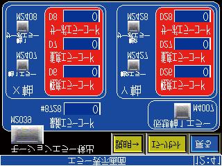


152 Demonstration machine operation panel Start 立上げ画面 screen The error エラー表示画面は各モード共通です display screen is common to all modes. 9-3
153 PLC M M Motion CPU SM PLC D D Motion CPU SD Range used as the user device in the motion CPU program for this practice Range used as the user device in the PLC CPU program for this practice Range used as the user device in the motion CPU program for this practice Range used as the user device in the PLC CPU program for this practice : Positioning control device : Auto refresh device : User device 9-4
 System settings 1) Double-click the [System Setting] \"Basic Setting\" tab in the project window for the new project created at section 8.3. Double-click! 2) Click the [Import Multiple CPU Parameter] button at the Basic Setting dialog box that appears.")

154 9.3 System Settings It is first of all necessary to specify system settings at MT Works2. (1) System settings 1) Double-click the [System Setting] "Basic Setting" tab in the project window for the new project created at section 8.3. Double-click! 2) Click the [Import Multiple CPU Parameter] button at the Basic Setting dialog box that appears. 2) Click! Go to next page POINT Import Multiple CPU Parameter This section introduces the function used to specify settings at the motion CPU side also using the PLC side CPU parameters set at section Setting mistakes will be minimized! If not using "Import Multiple CPU Parameter" Click the "Multiple CPU Settings" tab. Go to page
 Click the Browse button at the dialog box used to open a project, and select a project for which PLC side CPU parameters have been")
 Check! 6) Click! 6) Click the \"Multiple CPU Setting\" tab, and ensure that the \"No. of CPU\" is \"2\". 7) Click the CPU No.")
155 From previous page 3) Select! 3) Click the Browse button at the dialog box used to open a project, and select a project for which PLC side CPU parameters have been set. 4) Click the Open button. 4) Click! 5) Click the Yes button at the Import Multiple CPU Parameter dialog confirmation message box that appears. 6) Check! 6) Click! 6) Click the "Multiple CPU Setting" tab, and ensure that the "No. of CPU" is "2". 7) Click the CPU No.2 Refresh button in the "Multiple CPU High Speed Transmission Area Setting" tab. 7) Click! Go to next page 9-6
 \"M496\" \"SM496\" 8) Change! 9) Click the OK button. 9) Click! (11) Click! 10) Ensure that \"All station stop by stop error of CPU2\" is selected at \"Operation Mode\".")
156 From previous page 8) An Automatic Refresh Setting dialog box for the CPU2 then appears. Change the start of Setting No. 5 as follows. (A special relay is used at the motion side.) "M496" "SM496" 8) Change! 9) Click the OK button. 9) Click! (11) Click! 10) Ensure that "All station stop by stop error of CPU2" is selected at "Operation Mode". 11) Once confirmed, click the "System Basic Setting" tab in the Basic Setting dialog box. 10) Check! Go to 12) on page * Pages 9-8 to 9-9 describe the setting method when not reusing multiple CPU parameters. 9-7
157 [If not using "Reuse Multiple CPU Parameters"] From page 9-5 a) Set the "1st row" of the "Extension Base" to "10 Slots/GOT (Bus connection)". a) Set! b) Set "No. of CPU" to "2". b) Set! c) Click the CPU No.1 Refresh button at "Multiple CPU High Speed Transmission Area Setting". c) Click! d) Set! d) An Automatic Refresh Setting dialog box then appears. Specify the automatic refresh settings for the CPU1 as follows. "Setting No.1 - Points" : "48" "Setting No.1 - Start" : "M3072" "Setting No.2 - Points" : "64" "Setting No.2 - Start" : "D640" "Setting No.3 - Points" : "50" "Setting No.3 - Start" : "M6000" "Setting No.4 - Points" : "800" "Setting No.4 - Start" : "D6000" Go to next page 9-8
158 From previous page e) Set! e) Click! f) Click! e) Click the "CPU2" tab, and specify the automatic refresh settings for the CPU No.2 as follows. "Setting No.1 - Points" : "66" "Setting No.1 - Start" : "M2000" "Setting No.2 - Points" : "640" "Setting No.2 - Start" : "D0" "Setting No.3 - Points" : "50" "Setting No.3 - Start" : "M6800" "Setting No.4 - Points" : "800" "Setting No.4 - Start" : "D6800" "Setting No.5 - Points" : "4" "Setting No.5 - Start" : "SM496" f) When settings are complete, click the OK button. h) Click! g) The display then returns to the Basic Setting dialog box. Ensure that "All station stop by stop error of CPU2" is selected at "Operation Mode". g) Check! h) Once confirmed, click the "System Basic Setting" tab in the Basic Setting dialog box. Go to next page 9-9

159 From previous page (12) Check! 12) Ensure that the following settings are as shown. "Forced Stop" : Nothing "Operation Cycle" : Default Setting "Operation at STOP to RUN" : M2000 is turned on by switching from STOP to RUN. 13) Once set, click the OK button at the Basic Setting dialog box. (13) Click! (14) Basic setting is now complete. System configuration settings are described at (2) from the following page. 9-10
 A Motion Slot Setting dialog box then appears. Select \"Servo External Signal Module\" - \"Q172DLX\" at \"Motion Module\". 3) When settings are complete, click the Detail Setting button. (3) Click!")
160 (2) Motion slot settings 1) To specify settings for the slot 4 servo external signal input module, double-click main base slot 4 in the system configuration window. (1) Double-click! (2) Select! 2) A Motion Slot Setting dialog box then appears. Select "Servo External Signal Module" - "Q172DLX" at "Motion Module". 3) When settings are complete, click the Detail Setting button. (3) Click! (4) Check! 4) A Q172DLX Setting dialog box then appears. Ensure that the DOG signal contacts are set as follows. DOG1: Normal Open DOG2: Normal Open (5) Click! 5) When settings are complete, click the OK button. The display then returns to the Motion Setting dialog box. Click the OK button. 6) To specify settings for the slot 5 synchronous encoder input module, double-click main base slot 5 in the system settings window. (6) Double-click! Go to next page 9-11
 When settings are complete, click the Detail Setting button. (8) Click! (9) Set! 9) A Q172DEX Setting dialog box then appears.")
\" (set \"High-speed Read Data Setting\" to \"Not used\", and \"Input Response Time (operation mode)\" to \"0.")
 To specify settings for the slot 3 analog input module, double-click main base slot 3 in the system settings window. (11) Double-click!")
161 From previous page 7) A Motion Slot Setting dialog box then appears. Select "Sync. ENC. Input Module" - "Q172DEX" at "Motion Module". (7) Select! 8) When settings are complete, click the Detail Setting button. (8) Click! (9) Set! 9) A Q172DEX Setting dialog box then appears. Select the "P1" check box at "MAN-PLS/Sync. ENC Setting", and then select "Q171ENC-W8 (ABS [PLS])" (set "High-speed Read Data Setting" to "Not used", and "Input Response Time (operation mode)" to "0.4".) (10) Click! 10) When settings are complete, click the OK button. The display then returns to the Motion Setting dialog box. Click the OK button. 11) To specify settings for the slot 3 analog input module, double-click main base slot 3 in the system settings window. (11) Double-click! 12) A Motion Slot Setting dialog box then appears. Select "Analog Input" at "PLC Module". 13) When settings are complete, click the Detail Setting button. (12) Select! (13) Click! Go to next page 9-12

 Click!")
162 From previous page (14) Select! 14) An Analog Module Setting dialog box then appears. Select "0040" at "First I/O No.", and then specify the following setting. Switch 1 "CH1": 0 to 10V 15) When settings are complete, click the OK button. The display then returns to the Motion Setting dialog box. Click the OK button. (15) Click! 16) System configuration settings are now complete. 9-13
![(3) Amplifier settings 1) Double-click [System Setting] [SSCNET Structure] in the](/docs-images/74/71280117/images/163-0.jpg "Project window. Double-click! 2) An SSCNET Structure window appears.")
 servo amplifier from the left in the SSCNET Structure window.")
163 (3) Amplifier settings 1) Double-click [System Setting] [SSCNET Structure] in the Project window. Double-click! 2) An SSCNET Structure window appears. 3) To specify settings for the first servo amplifier and servo motor, double-click the first (d01) servo amplifier from the left in the SSCNET Structure window. 3) Double-click! Go to next page 9-14
-B\". 5) Ensure that the \"Axis No.\" is \"1\".")
 To then specify settings for the second servo amplifier and servo motor, double-click the second (d02) servo")
164 From previous page (4) Check! (5) Check! 4) An Amplifier Setting dialog box then appears. Ensure that the "Amplifier Model" is "MR-J4(W)-B". 5) Ensure that the "Axis No." is "1". 6) Once set, click the OK button at the Amplifier Setting dialog box. (10) Click! 7) To then specify settings for the second servo amplifier and servo motor, double-click the second (d02) servo amplifier from the left in the System Setting window. (7) Double-click! Go to next page 9-15
165 From previous page (4) Check! (5) Check! (8) An Amplifier Setting dialog box then appears. Ensure that the "Amplifier Model" is "MR-J4(W)-B". (9) Ensure that the "Axis No." is "2". (10) Once set, click the OK button at the Amplifier Setting dialog box. (10) Click! (11) Settings for the first (d01) and second (d02) servo amplifier and servo motor are now complete. 9-16

 and retry the relativity")
166 (4) Relativity check, saving 1) When motion slot settings and amplifier settings are complete, click [Relative Check/ Convert] on the [Check/Convert] menu. Click! 2) Ensure that there are no errors at the output window. If any error items are displayed in the output window, edit the setting(s) and retry the relativity check. 3) Click [Save] on the [Project] menu. System settings are now complete. Click! 9-17

![(1) Double-click [Servo Data Setting] [Servo Data] in](/docs-images/74/71280117/images/167-1.jpg "the project window. Double-click!")

167 9.4 Servo Data Input Operation After specifying system settings, specify servo data settings. (1) Double-click [Servo Data Setting] [Servo Data] in the project window. Double-click! (2) A Servo Data Setting window appears. Set! (3) Specify the content shown on the left for the Axis 1 Fixed Parameter. Go to next page 9-18
 Specify the content shown on the left for the Axis 1 JOG Operation Data settings.")

168 From previous page (4) Specify the content shown on the left for the Axis 1 Home Position Return Data settings. Set! Set! (5) Specify the content shown on the left for the Axis 1 JOG Operation Data settings. (6) Specify the content shown on the left for the Axis 1 Servo External Signal Parameter. Note: The values set for Axis 1 differ from those for Axis 2, and therefore care should be taken if copying Axis 1 settings to Axis 2. Go to next page 9-19


 Double-click [Servo Data Setting] [Servo Parameter] in")
 MR Configurator2 starts up.")
169 From previous page (7) Use the same operation to specify the content shown below for the Axis 2 Fixed Parameter, Home Position Return Data, and JOG Operation Data. POINT By right-clicking the screen on the left, blocks can be copied and pasted. (8) Double-click [Servo Data Setting] [Servo Parameter] in the Project window. Double-click! (9) MR Configurator2 starts up. MR Configurator2 is software used to set servo amplifier parameters and so on. Go to next page 9-20
![From previous page Click! (10) Click [Function display] [Component parts] in the Parameter Setting screen display selection tree, and then specify the following settings. Set! Absolute pos.](/docs-images/74/71280117/images/170-1.jpg "detection system sel. : Enabled (Used in ABS pos. detect system) (11) Click the [Update Project] button. Click! (12) Click the [Yes] button to update the servo parameter changes. Click! (13) Switch to Axis 2 and set the parameters in the same manner.")
170 From previous page Click! (10) Click [Function display] [Component parts] in the Parameter Setting screen display selection tree, and then specify the following settings. Set! Absolute pos. detection system sel. : Enabled (Used in ABS pos. detect system) (11) Click the [Update Project] button. Click! (12) Click the [Yes] button to update the servo parameter changes. Click! (13) Switch to Axis 2 and set the parameters in the same manner. Go to next page 9-21

![(15) Click the [Yes] button to](/docs-images/74/71280117/images/171-1.jpg "update the servo parameter changes.")
 Double-click [Servo Data")
![Setting] [Parameter Block] in the](/docs-images/74/71280117/images/171-3.jpg "Project window. Double-click!")
171 From previous page (14) Click the [Update Project] button. Click! (15) Click the [Yes] button to update the servo parameter changes. Click! (16) Exit MR Configurator2. (17) Double-click [Servo Data Setting] [Parameter Block] in the Project window. Double-click! Go to next page 9-22

 Specify Parameter Block No.")
 Specify Parameter Block No.")
172 From previous page (18) The Parameter Block Setting screen appears. (19) Specify Parameter Block No.1 settings as shown on the left. (20) Specify Parameter Block No.2 settings as shown on the left. Go to next page 9-23
173 From previous page (21) When all servo data settings are complete, click [Save] on the [Project] menu. Servo data settings are now complete. 9-24
174 9.5 Practice Motion SFC Programs Program list These sequence/motion SFC programs have been created for operation purposes on the assumption that MT Works2 (for Q172DSCPU) be used. An explanatory drawing of the demonstration machine GOT operation panel is shown in item 9.2. The sequence program and motion SFC program used for practice are shown in the following list. Initial processing, operation type selection, JOG operation, zeroing, and motion SFC program startup are performed from the sequence program. Standby point positioning, positioning by selecting positioning points at the GOT operation panel, and positioning by entering positioning addresses at the GOT operation panel are practiced using the motion SFC program. Refer to the respective descriptions of each program in this manual for details. Normal execution Startup with sequence program Startup with motion SFC program Sequence program *****Real mode***** 170 Real mode M1040 Real mode main start trigger PLS SET M1040 Real mode main start trigger M1041 Real mode main start request [Real mode main] Motion SFC program No.10 M1041 Real mode main start request <Motion SFC program No.10 start request> DP.SFCS H3E1 K10 M1050 D3050 Completion Completion device status [Standby point positioning] Motion SFC program No.20 [Point selection positioning] Motion SFC program No.30 RST M1041 Real mode main start request [Address designation positioning] Motion SFC program No.40 Motion SFC program parameters No. of transitions No. Program name Automatic start END operation Execution timing 10 Real mode main No - 3 Normal 20 Standby point positioning No - 3 Normal 30 Point selection No - 3 Normal 40 Address indirect designation No - 3 Normal 9-25
175 Start program from sequence program Real mode main Standby point positioning Point selection Address indirect designation 9-26
176 モーション Start program SFCfrom プログラム リアルモードメイン プログラム motion SFC program [Real mode main] program No.10からの起動プログラム [Standby [ 待機点位置決め point positioning] ] プログラム Program No.20 No.20 [Point [ ポイント選択 selection positioning] ] プログラムProgram No.30 No.30 Standby point positioning Point selection [Address[ アドレス間接指定 indirect designation] ] プログラム Program No.40 No.40 Address indirect designation Start program from sequence program [Zeroing program] Servo program K1 and K2 are started directly with an SVST command from the sequence program. [Jog operation] JOG start devices M3202, M3203, M3222, and M3223 are started by turning them ON directly from the sequence program. 9-27
177 Q03UD sequence program **** Initial イニシャル処理 processing***** SM403 M500 M RUN scan 後 1only ス PCPU 準備 ready GOT スイッ switch servo ON OFF キャンのafter RUN みOFF 完了フラク complete チサーボON ****Operation 操作モードの切換え mode change***** M M M M M Axis 軸 1サーホ レ 1 servo Axis 軸 2サーホ レ 2 servo JOG, 原点 Real リアルモ Advanced アドバン ready テ ィ ready テ ィ home スイッチpos. mode ードスイ synchronous スト同期 switch switch ッチ control 制御スイ switch ッチ M M M JOG, 原点 home スイッチpos. switch Real リアルモ mode ードスイ switch ッチ Advanced アドバン synchronous スト同期 control 制御スイ switch ッチ M M M JOG, 原点 home スイッチpos. Real リアルモ mode ードスイ Advanced アドバン synchronous スト同期 switch switch ッチ control 制御スイ switch ッチ ****JOG JOG operation 運転と原点復帰 and zeroing***** M M M M JOG/home 原点 GOT スイッ switch Axis 軸 1-1 正転 - Axis 軸 1-1 逆転 - reverse pos. モードmode axis チ軸 1 正 forward JOG 始動指 rotation JOG 始動指 JOG forward 転 JOG rotation 令 start 令 command rotation JOG start JOG command M M All 全軸サーホ axis servo ON ON M JOG/home 原点 pos. mode モード M Real リアルモ mode ード M Advanced アドバン control スト制御 M Axis 軸 forward 正転 rotation JOG 始動 JOG 指 start command 令 Start 始動受付 accept flag フラク M M M GOT スイッ switch axis チ軸 1 逆 reverse 転 JOG rotation JOG Axis 軸 1-1 逆転 reverse JOG 始動指 rotation 令 JOG start command M Axis 軸 1-1 正転 forward rotation JOG 始動指 JOG start 令 command M Axis 軸 1- 逆転 reverse rotation JOG 始動 JOG 指 start command 令 Start 始動受付 accept flag フラク M M M GOT スイッ switch axis チ軸 2 正 forward 転 JOG JOG Axis 軸 2-2 正転 - forward JOG 始動指 rotation 令 JOG start command M Axis 軸 2-2 逆転 - reverse rotation JOG 始動指 JOG start 令 command M Axis 軸 2- - forward 正転 rotation JOG 始動 JOG 指 start command 令 Start 始動受付 accept flag フラグ 9-28
178 M M M GOT スイッ switch axis チ軸 2 逆 reverse 転 JOG rotation JOG Axis 軸 2-2 逆転 reverse JOG 始動指 rotation 令 JOG start command M Axis 軸 2-2 正転 forward rotation JOG 始動指 JOG start 令 command M Axis 軸 22- reverse 逆転 rotation JOG 始動 JOG 指 start command 令 Start 始動受付 accept flag フラグ M GOT スイッ switch zeroing チ原点復帰 PLS M1021 Zeroing 原点復帰 trigger トリガ M Zeroing 原点復帰 trigger トリガ SET M1022 Axis 軸 1 1 zeroing 原点復 request 帰要求 SET M1023 Axis 2 軸 zeroing 2 原点復 request 帰要求 M Axis 軸 1 原点復 1 zeroing 帰要求 request U3E1\G516.0 軸始動受 Axis start accept 付 DPSVST DP.SVST H3E1 "J1" J1 K1 M1030 D3030 Completion 完了デバ Completion 完了ステ device イス status ータス RST M1022 Axis 軸 1 原点復 zeroing request 帰要求 M Axis 軸 2 2 zeroing 原点復 request 帰要求 U3E1\G516.1 軸始動受 Axis start accept 付 DPSVST DP.SVST H3E1 J2 "J2" K2 M1032 D3032 Completion 完了デバ Completion 完了ステ device イス status ータス RST M1023 Axis 軸 2 zeroing 2 原点復 request 帰要求 ****Real リアルモード mode***** M Real リアルモmode ード PLS M1040 Real リアルモ mode main start ードメイ trigger ン始動トリガ 9-29
179 M1040 M1041 M1040 Real リアルモ mode main ードメイ start trigger ン始動トリガ SET M1041 Real リアルモ mode main ードメイ start request ン始動要求 M1041 Real リアルモ mode main ードメイ start request ン始動要求 DP.SFCS H3E1 K10 M1050 Completion 完了デバ device イス D3050 Completion 完了ステ status ータス RST M1041 Real リアルモ mode main ードメイ start request ン始動要求 ****Advanced* アドバンスト制御 control***** ***** M6002 M Advanced アドバン Performing control スト制御 advanced control M3075 Advanced アト ハ ンスト control 制御 M3075 Advanced アト ハ ンスト control 制御 M1060 Advanced アドバン control スト制御 start trigger 始動トリガ PLS SET M1060 Advanced アドバン control スト制御 start trigger 始動トリガ M1061 Advanced アト ハ ンスト control 制御メイ main start request ン始動要求 M1061 Advance アト ハ ンスト control 制御メイ main start ン始動要 request 求 DP.SFCS H3E1 K100 M1070 Completion 完了デバ device イス D3070 Completion 完了ステ status ータス RST M1061 Advance アト ハ ンスト control 制御メイ main start request ン始動要求 259 END 9-30
180 9.5.2 Initial processing The following is an example of a program used to start all motion CPU servo axes. Both the PLC CPU and motion CPU are set to the RUN status. With the settings for this practice, a servo data and servo parameter check is performed after the motion CPU status changes from STOP to RUN. If there are no errors, the motion CPU turns the PCPU READY complete flag (SM500) ON. The PLC CPU receives the PCPU READY complete flag (SM500) as M500 through auto refresh. When there are no errors at either the PLC CPU or motion CPU, by turning M1000 ON at the demonstration machine operation panel, an all axis servo ON command is sent from the PLC CPU, and motion CPU startup is completed. (1) Program example ****Initial processing***** 0 SM403 M500 M scan only OFF after RUN PCPU ready complete flag GOT switch servo ON M3074 All axis servo ON Demonstration machine operation panel [Timing chart] Motion CPU RUN (M2000) PCPU ready complete flag SM500 M1000 All axis servo ON command M3074 (M3074) All axis servo ready status 9-31
181 9.5.3 JOG Operation JOG operation is used to perform operation manually only while buttons are held down. The devices shown in the table below and content (acceleration/deceleration time) of the parameter blocks set in JOG data are used. By setting the speed in the JOG speed setting register (table below), and turning ON a forward rotation JOG start signal (M3202/axis 1) or reverse rotation JOG start signal (M3203/axis 1), JOG operation starts. JOG operation stops when the JOG start signal is turned OFF. (1) JOG operation speed setting register Axis No. JOG operation speed setting register Upper Lower 1 D641 D640 2 D643 D642 3 D645 D644 4 D647 D646 5 D649 D648 6 D651 D650 7 D653 D652 8 D655 D654 Setting range 1 to Speed setting range mm inch degree PULSE Unit 10-2 mm / min Setting range 1 to Unit 10-3 inch / min Setting Setting Unit range range 1 to / min 1 to Unit pulse / s (2) Forward/reverse rotation JOG start signals Control axis Forward rotation Reverse rotation Axis 1 Axis 2 Axis 3 Axis 4 Axis 5 Axis 6 Axis 7 Axis 8 M3202 M3222 M3242 M3262 M3282 M3302 M3322 M3342 M3203 M3223 M3243 M3263 M3283 M3303 M3323 M3343 (3) Program example 1) JOG operating condition items Item Condition Control axis Axis 1 Axis 2 JOG operation command input Forward rotation (M1010) Reverse rotation (M1011) Forward rotation (M1012) Reverse rotation (M1013) 9-32
182 2) Example of program in which JOG operation is performed by starting axes 1 and 2 independently The JOG speed can be set freely from the demonstration machine operation panel. ****JOG operation and home position return***** 53 M6000 M1010 M3202 M3203 JOG/home pos. mode GOT switch axis 1 forward rotation JOG Axis 1 - forward rotation JOG start command M2001 Axis 1 - reverse rotation JOG start command M3202 Axis 1 - forward rotation JOG start command Start accept flag M1011 M3203 M3202 GOT switch axis 1 reverse rotation Axis 1 - reverse rotation JOG start command M2001 Axis 1 - forward rotation JOG start command M3203 Axis 1 - reverse rotation JOG start command Start accept flag M1012 M3222 M3223 GOT switch axis 2 forward JOG Axis 2 - forward rotation JOG start command M2002 Axis 2 - reverse rotation JOG start command M3222 Axis 2 - forward rotation JOG start command Start accept flag M1013 M3223 M3222 GOT switch axis 2 reverse JOG Axis 2 - Axis 2 - forward reverse rotation JOG rotation JOG start command start command M2002 M3223 Axis 2 - reverse rotation JOG start command Start accept flag 9-33
183 M1010 : Axis 1 forward rotation JOG command M1011 : Axis 1 reverse rotation JOG command M1012 : Axis 2 forward rotation JOG command M1013 : Axis 2 reverse rotation JOG command D641, D640 : Axis 1 JOG speed setting register D643, D642 : Axis 2 JOG speed setting register Axis 軸 22 (Y) Demonstration 実習機操作盤 machine (GOT) operation panel (GOT) Axis 軸 1(X) 1 (X) [Timing chart] Forward rotation 正転 Reverse rotation 逆転 JOG 速度 speed M1010 M3202 M1011 M
184 9.5.4 Zeroing The following is an example of a program in which a servo program is run and zeroing is performed by executing an SVST command from a ladder program. Actual details of the zeroing operation are determined by the zeroing data at the motion CPU side and the parameter block (acceleration/deceleration time). The zeroing operation for each axis is as follows. Zeroing is performed by turning ON the demonstration machine operation panel M1020. Axis 1/2: Set with proximity dog. After starting, the motor rotates in the zeroing direction, and the rotation is complete when the home position dog changes from ON to OFF. [Servo program] Real <K 1> ZERO Axis 1 Axis 1 servo program Start point DOG (mm) Real <K 2> ZERO Axis 2 Axis 2 servo program (mm) 10 5 Start 0 DOG
185 [Sequence program] M1020 GOT switch zeroing PLS M1021 Zeroing trigger M1021 Zeroing trigger SET M1022 Axis 1 zeroing request SET M1023 Axis 2 zeroing request M1022 U3E Axis 1 zeroing request Axis start accept <Servo program start request> DP.SVST H3E1 J1! K1 M1030 D3030 Completion Completion device status RST M1022 Axis 1 zeroing request M1023 U3E Axis 2 zeroing request Axis start accept <Servo program start request> DP.SVST H3E1 J2 K2 M1032 D3032 RST M1023 Axis 2 zeroing request 9-36
186 MEMO 9-37
187 9.5.5 Main routine motion SFC program (real mode operation) This is a motion SFC program run as the main routine when performing real mode positioning operation (other than manual operation). Other motion SFC programs used to perform various types of operation when in real mode from this main routine motion SFC program are started as subroutines. (1) Motion SFC program started from main routine motion SFC program. Motion SFC program No. Program name Reference section 20 Standby point positioning Point selection Address indirect designation (2) Program example Real リアルモート メイン mode main モーション Motion SF SFC program プログラム No.10 [F 100] //Lamp ランプの点灯 ON SET SET M9 M9 Speed 速度変更 change P0 IFB1 [G [G 100] 100] //Mode モード選択スイッチのチェック selection switch check!m6801 "Standby M0=ON point positioning" called when M0 M2001( = ON 軸 1 始動受付フラグ )=OFF M2001 M2002( 軸 (axis 2 始動受付フラグ 1 start accept )=OFF flag) = OFF M2002 のときに 待機点位置決め を呼出 (axis 2 start accept flag) = OFF [G 101] 101] //Standby 待機点位置決め始動 point positioning start M0*!M2001*!2002 M0*!M2001*!M2002 CLR 速度変更 Speed change [F 101] [F 101] //Lamp OFF // ランプの消灯 RST RST M9 M9 Standby 待機点位置決め point positioning サブルーチン呼出により呼び出した Axis stands by at that position until プログラムが終了するまで その位置 program called by calling sub-routine is で待機する complete. [G4095] //Program プログラム終了 completion && start 始動受付復帰待ちダミー accept return wait dummy NOP END IFE1 P0 9-38
188 "Point M1=ON selection" called when M1 M2001( = ON 軸 1 始動受付フラグ )=OFF M2001 K30<=D2000<=K32 (axis 1 start accept flag) = OFF K30 のときに ポイント選択 を呼出 <=D2000 <= K32 "Address M2=ON indirect designation" called when M2001( = ON 軸 1 始動受付フラグ )=OFF M2001 M2002( 軸 (axis 2 始動受付フラグ 1 start accept )=OFF flag) = OFF M2002 のときに アドレス間接指定 を呼出 (axis 2 start accept flag) = OFF [G 102] 102] //Positioning 選択したポイントへ位置決め始動 at selected point start M1*M2001*(D2000>=K30)*(D2000<=K32) M1*!M2001*(D2000>=K30)*(D2000<=K32) [G 103] 103] //Address アドレス可変位置決め始動 variable positioning start M2*!M2001*!M2002 Point ポイント選択 selection Axis サブルーチン呼出により呼び出した stands by at that position until program プログラムが終了するまで その位置 called by calling sub-routine is で待機する complete. [G4095] //Program プログラム終了 completion && start 始動受付復帰待ちダミー accept return wait dummy NOP アドレス間接指定 Address indirect designation サブルーチン呼出により呼び出した Axis stands by at that position until プログラムが終了するまで その位置 program called by calling sub-routine で待機する is complete. [G4095] //Program プログラム終了 completion && start 始動受付復帰待ちダミー accept return wait dummy NOP 9-39
189 9.5.6 Standby point positioning [G 102] //Positioning at selected point start M1*M2001*(D2000>=K30)*(D2000<=K32) [Real mode main] program [ リアルモードメイン ] プログラム Standby point refers to a work standby position at other than the mechanical home position. (There may be times when the position is the same as the home position.) In this program example, the axis returns to the standby point by specifying the standby point address and performing positioning. By running the servo program with a motion SFC program motion control step, operation is performed based on the content of the executed servo program data and the parameter block. Standby point positioning "Standby point positioning" called when M0 = ON M2001 = OFF M2002 = OFF Standby point positioning 待機点位置決め モーションSFCプログラム No.20 Motion SFC program No.20 [F200] //Lamp ランプ点灯 ON SET M10 [K20: Real] リアル ] ABS-2 ABS-2 Axis 軸 1 1, 0.0 μm 0.0 m Axis m 軸 2, 0.0 μm Composite speed mm/min Dwell 合成速度 mm/min msec ト ウェル 100 msec [G4095] //Program フ ロク ラム終了 completion & 始動受付復帰待ちタ ミー & start accept return wait dummy NOP NOP Ensures transition to next step with "WAIT" type transition after completion 次のステップへ移行するようにします of current servo program. WAIT タイプのトランジションにより,... 実行中のサーボプログラムの動作完了後に, [F201] //Lamp ランプ点灯 ON RST M10 END 9-40
190 9.5.7 Point selection positioning [Real [ リアルモードメイン mode main] ] プログラム program This is an example of a basic point selection program. By entering the point No. (servo program No. in this example) at the GOT operation panel and then pressing the START button, the axis is positioned at the address registered beforehand. Point selection "Point selection" called when M1 = ON M2001 = OFF K30 <=D2000 <= K32 ホ イント選択 Point selection Motion モーションSFC プログラム program No.30 No.30 [F300] //Lamp ランプの点灯 ON SET M11 M11 Runs GOT relevant 操作パネルの値 servo がprogram 30,31,32 if の場合に該当するサーボプログラムを実行 GOT operation value is 30, 31, or 32. IFB1 [G300] //When 入力値 input =30のとき value = 30 D2000==K30 [G301] //When 入力値 input =31のとき value = 31 D2000==K31 [G302] //When 入力値 input =32のとき value = 32 D2000==K32 [K30: リアル Real] ] ABS-1 ABS-1 軸 1, μm Axis m 速度 mm/min Speed mm/min [K30: [K31: リアル Real] ] ABS-1 1 ABS-1 軸 1, μm Axis m 速度 mm/min Speed mm/min [K32: [K30: リアル Real] ] ABS-1 1 ABS-1 軸 1, μm Axis m 速度 mm/min Speed mm/min [G4095] //Program フ ロク ラム終了 completion & 始動受付復帰待ちタ ミー & start accept return wait NOP dummy NOP [G4095] //Program フ ロク ラム終了 completion & 始動受付復帰待ちタ ミー & start accept return wait NOP dummy NOP [G4095] //Program フ ロク ラム終了 completion & 始動受付復帰待ちタ ミー & start accept return wait NOP dummy NOP IFE1 [F301] //Lamp ランプの消灯 OFF RST M11 M11 END END Note: There are two "=" symbols in the D2000==K30, D2000==K31, and D2000==K32 commands in [G300], [G301], and [G302]. 9-41
191 9.5.8 Address indirect designation positioning This is an example of positioning at an address other than the previously registered position. The axis 1 and axis 2 addresses are computed based on the GOT operation panel values, and then stored in D2020. Positioning is performed by pressing the START button. Even number addresses in the unused data register D, link register W, and motion device # can be used for indirect setting. In addition to addresses, speed, dwell, M-codes, and parameter blocks can also be set indirectly. [Real [ リアルモードメイン mode main] program ] プログラム G103 Address indirect designation "Address indirect designation" called when M2 = ON M2001 = OFF M2002 = OFF G4095 Address アト レス間接指定 indirect designation Motion モーション SFC プログラム program No.40 No.40 [F400] //Lamp ランプの点灯 ON SET SET M12 M12 //For address designation <32 bit> // アドレス指定用 (32bit) D2020L=D2000L*K10000 D2020L=D2000L*K10000 [K40: Real] リアル ] 1 ABS-2 1 Axis 1 軸 1, D 2020 μm m Axis 2 軸 2, D 2020 μm m Composite speed mm/min 合成速度 mm/min Axis 軸 1,21, のアドレスを 2 addresses D2020,D2021 set as のD2020, D ビットデータとする bit data. [G4095] //Program フ ロク ラム終了 completion & 始動受付復帰待ちタ ミー & start accept return wait NOP dummy NOP [F401] //Lamp ランプの消灯 OFF RST M12 M12 END 9-42
192 9.5.9 Changing the speed (CHGV) [additional practice] This is an example of a program used to change the speed in three stages at the GOT operation panel and then temporarily stop operation. Changes to speed are made by executing a speed change command (CHGV command) with a motion SFC program operation control step. When setting the speed with a CHGV command, operation stops temporarily when setting the speed to "0", and the remainder of the operation is performed when the speed is changed again by setting to a value other than 0. (1) CHGV speed change request command Describes the axis No. for which the speed is to be changed, and the changed speed. CHGV(K1,K30000) (2) Speed change setting range K K[ [speed 変更後速度 after change] ] to D8191 W0 D0~D8191 to 1FFF #0 W0~1FFF to #7999 #0~#7999 速度変更を行う軸 No.(1~8) Speed change setting range mm inch degree pulse Setting Unit Setting Unit Setting Unit Setting Unit to to to to degrees/ pulse/s mm/min inch/min min POINT If setting the speed with the CHGV command, set a value 100 times (mm) or 1000 times (inch/degrees) the actual speed. Example Axis No. (1 to 8) for which speed changed If setting the speed to mm/min, set a value of " ". (3) Program example 1) Speed change conditions Item Condition Control axis Axis 1 Axis 2 Speed change command input M20 Speed after change: 2000 mm/min M21 Speed after change: 1000 mm/min M22 Speed after change: 500 mm/min M23 Temporary stop (0 mm/min) 9-43
193 2) Speed change program example [[Real リアルモードメイン mode main] ] program プログラム Real リアルモート メイン mode main F100 Speed 速度変更 change リアルモードメイン 起動に合わせて Speed change started in conjunction 速度変更 を起動 with Real mode main start. P0 IFB1 G100 CL R 速度変更 Speed change リアルモードメイン 終了に合わせて Speed change finished in conjunction 速度変更 を終了 with Real mode main end. F101 IFB END Speed 速度変更 change Motion モーション SFC SFCprogram プログラムNo.200 No.200 IFE1 P0 IFB [G2000] //Is there no high-speed, speed change request? //M2001: 高速の速度変更要求がないか Axis 1 start accept (ON while? started) //M2061: //M2001: During 軸 1 始動受付 axis 1 speed ( 始動中 change ON) (ON only when starting speed change) //M2061: 軸 1 速度変更中 ( 変速開始時のみON) //M2128: During axis 1 auto deceleration (ON during //M2128: auto 軸 deceleration) 1 自動減速中 ( 自動減速中 ON) M20*M2001*!M2061*!M2128 [G2001] //Is [G2001] there no medium-speed, speed change request? //M2001: 中速の速度変更要求がないか Axis 1 start accept (ON while? started) //M2061: During axis 1 speed change (ON only //M2001: 軸 1 始動受付 ( 始動中 ON) when starting speed change) //M2128: //M2061: During 軸 1 速度変更中 axis 1 auto ( deceleration 変速開始時のみ (ON ON) during //M2128: auto 軸 deceleration) 1 自動減速中 ( 自動減速中 ON) M21*M2001*!M2061*!M2128 [G2002] //Is there no low-speed, speed change request? //M2001: 低速の速度変更要求がないか Axis 1 start accept (ON while? started) //M2061: //M2001: During 軸 1 始動受付 axis 1 speed ( 始動中 change ON) (ON only when starting speed change) //M2061: 軸 1 速度変更中 ( 変速開始時のみON) //M2128: During axis 1 auto deceleration (ON during //M2128: auto 軸 deceleration) 1 自動減速中 ( 自動減速中 ON) M22*M2001*!M2061*!M2128 [G2003] //Is there no temporary stop request? //M2001: 一時停止要求はないか Axis 1 start accept?(on while started) //M2061: //M2001: During 軸 1 始動受付 axis 1 speed ( 始動中 change ON) (ON only when starting speed change) //M2061: 軸 1 速度変更中 ( 変速開始時のみON) //M2128: During axis 1 auto deceleration (ON during //M2128: auto 軸 deceleration) 1 自動減速中 ( 自動減速中 ON) M23*M2001*!M2061*!M2128 IFE1 [F2000] [F2001] [F2001] //Speed change request ( mm/min) //Speed change request ( mm/min) // 速度変更要求 ( mm/min) // 速度変更要求 (1000mm/min) CHGV(K1,K200000) CHGV(K1,K100000) Speed 速度変更命令 change command (Set ( 0.01mm/min 0.01mm/min units) 単位で設定 ) [F2002] [F2002] //Speed change request ( mm/min) // 速度変更要求 (500.00mm/min) CHGV(K1,K50000) [F2003] //Speed change request (0 mm/min; stop) //Used // 速度変更要求 as temporary (0mm/min: stop 停止 ) // 一時停止として使用 CHGV(K1,K0) P0 M2001=ON, N( 軸 M2061=OFF, 1 始動受付 ( 始動中 ON)) When M2128 = OFF M2061=OFF( 軸 1 速度変更中 ( 変速開始時のみON)) [M20 = ON: Speed change to 2000 mm/min] M2128=OFF( 軸 1 自動減速中 ( 自動減速中 ON)) のとき [M21 = ON: Speed change to 1000 mm/min] [M20=ON: 速度 2000mm/minに変更 ] [M22 = ON: Speed change to 500 mm/min] [M21=ON: 速度 1000mm/minに変更 ] [M23 = ON: Temporary stop (Speed: 0 mm/min] [M22=ON: 速度 500mm/minに変更 ] [M23=ON: 一時停止 ( 速度 0mm/min)] 9-44
194 [Timing chart] Speed 速度 V During 動作中 operation 2000mm/min 1000mm/min t CHGV M20 M21 M22 M2061 M23 POINT The speed cannot be changed while the start accept flag is OFF. The speed cannot be changed during zeroing, circular interpolation, or while decelerating. The speed can be changed within the 0 to start speed range. 9-45
 Double-click [Motion SFC Program] [Motion SFC Program Manager] in the Project window. (1) Double-click! (2) A Motion SFC Program Manager dialog box appears. Click the NEW button. (2) Click!")
195 9.6 Motion SFC Program Creation Procedure This section describes how to create motion SFC programs used to set motion control operation Creating a new motion SFC program To create a new motion SFC program, begin by specifying the "Program name". (1) Double-click [Motion SFC Program] [Motion SFC Program Manager] in the Project window. (1) Double-click! (2) A Motion SFC Program Manager dialog box appears. Click the NEW button. (2) Click! (3) Enter! (3) A New dialog box appears. Set the program No. for the motion SFC program being created. Enter "10" for the "Motion SFC program No.", and "Real mode main" for the "Motion SFC program name". (4) Click the OK button after entering. (4) Click! Go to next page 9-46

196 From previous page (4) The set motion SFC program appears in a list. Press the NEW button again to create a motion SFC program such as the following. No. 10 Real mode main Program name 20 Standby point positioning 30 Point selection 40 Address indirect designation (Motion SFC programs other than No.10 and No.20 created here will not be described in detail.) Refer to the section on motion SFC programs for operation described later to create. 9-47
 クリック Click!")

 Click the single execution type operation control step tool button ([F]) on the Program Edit screen.")
197 9.6.2 SFC diagram creation procedure Allocate SFC diagram symbols to create an SFC diagram. 1 (1) クリック Click!! (1) Select "10 Real mode main" from the motion SFC program list in the Motion SFC Program Management dialog box, and then click the OK button. (2) An Edit Program screen used to create individual motion SFC programs appears. (3) Click the single execution type operation control step tool button ([F]) on the Program Edit screen. (4) Click on a random position to allocate an SFC diagram symbol pointer. Multiple pointers can be allocated. When allocation is complete, right-click to clear the SFC diagram symbol. Go to next page 9-48
198 From previous page (5) Now, click each tool button in the same manner to allocate SFC diagram symbols as shown on the left. Real mode main : (Single execution type operation control step) : (Pointer) : (Jump) : (Shift transition) : (Wait transition) : (Sub-routine call/start step) : (END) (6) Connect the allocated SFC diagram symbols. Click the connect tool button at the Edit Program screen. Go to next page 9-49
199 From previous page (7) By moving the mouse cursor over an SFC diagram symbol, the shape of the cursor changes. Drag to connect the start of the motion SFC program and pointer. (8) Connect other SFC diagram symbols in the same manner. Real mode main If connections are mistaken, click the Select/Cut tool button at the Edit Program screen ( ), move the mouse cursor over the connecting line, and then click to cut the line. Go to next page 9-50
![From previous page (9) Click [Arrange] on the [Edit] menu at the Edit Program window. Arrange the allocated SFC diagram symbols. (9) Click! (10) Click!](/docs-images/74/71280117/images/200-0.jpg "(10) Set program Nos. and pointer Nos. for the allocated SFC diagram symbols. Click the Select/Cut tool button at the Edit Program screen. (11) Double-click!")

200 From previous page (9) Click [Arrange] on the [Edit] menu at the Edit Program window. Arrange the allocated SFC diagram symbols. (9) Click! (10) Click! (10) Set program Nos. and pointer Nos. for the allocated SFC diagram symbols. Click the Select/Cut tool button at the Edit Program screen. (11) Double-click! (11) Double-click a pointer (P). (12) Click! (12) A Pointer Number Setting dialog box appears. Enter "0" for the "Pointer Number", and then click the OK button. Pointer Nos. can be set fro 0 to for each motion SFC program. ("P0" for motion SFC program No.0 and motion SFC program No.10 are different.) Go to next page 9-51
 A Program Number Setting dialog box appears. Enter \"100\" for the \"Program No.")
 Program No. \"G100\" is set for the transition.")
201 From previous page (13) Pointer No. "0" is set. Next, double-click a transition (G). (13) Double-click! (14) A Program Number Setting dialog box appears. Enter "100" for the "Program No.", and then click the OK button. The program No. is a common number in the project. (14) Click! (15) Program No. "G100" is set for the transition. Set operation control steps (F) and transitions (G) in the same manner. Go to next page 9-52
 Double-click! (17) Click!")

202 From previous page (16) Next, double-click a sub-routine call/start step. (16) Double-click! (17) Click! (17) A Program Name Setting dialog box appears. Enter "Standby point positioning" for the "Motion SFC Program Name", and then click the OK button. Go to next page 9-53
203 From previous page (18) Program name "Standby point positioning" is set for the sub-routine call/start step. Set program Nos. and pointer Nos. for other SFC diagram symbols in the same manner as shown on the left. Real リアルモート メイン mode main F100 P0 P0 IFB1 IFB1 G100 G101 G102 G103 F101 Standby point positioning 待機点位置決め ポイント選択 Point selection Address indirect designation アドレス間接指定 END G4095 G4095 G4095 IFE1 IFE1 P0 P0 9-54

 When \"[F100]\" appears in the area on the right of the screen (step Edit Program screen), double-click.")

 An Instruction Wizard dialog box appears. Select as follows, and then press the OK button.")
204 9.6.3 Entering transition and operation control steps This section describes how to set conditional expressions and operational expressions for transitions and operation control steps allocated to SFC diagrams. Real mode main (1) Click operation control step "F100" to select. (2) Double-click! (2) When "[F100]" appears in the area on the right of the screen (step Edit Program screen), double-click. (3) Click! (3) An Edit Operation Control Program/Transition Program dialog box appears. Enter a comment and press the Enter key to start a new line. Click the Select Instruction button. Commands can be set by direct entry. If entering directly, continue from step (5). (4) An Instruction Wizard dialog box appears. Select as follows, and then press the OK button. Class : Bit Device Control Description : SET Description Example : SET M0 Go to next page 9-55
 Click the OK button at the conversion complete message that appears. (7) Click the Close button.")
205 From previous page (5) A "SET M0" command is set. Change "M0" to "M9". Press the Enter key again to start a new line, and then enter a comment and command. Click the Convert button after entering. (6) Click the OK button at the conversion complete message that appears. (7) Click the Close button. (8) The set command appears on the step Edit Program screen. Go to next page 9-56
206 From previous page (9) Set the operational expression and conditional expression for the following operation control programs and transition programs in the same manner. Real mode main リアルモート メイン F100 F100 P0 P0 IFB1 IFB1 G100 G101 G102 G103 F101 F101 Standby point 待機点位置決め positioning ポイント選択 Point selection Address indirect アドレス間接指定 designation END G4095 G4095 G4095 IFE1 P0 P0 [G100] [G101] [G102] [G103] [G4095] [F100] [F101] *(Logical product)!(logical negation) //Mode selection switch check!m6801 //Standby point positioning start M0*!M2001*!M2002 //Positioning at selected point start M1*!M2001*(D2000>=K30)*(D2000<=K32) //Address variable positioning start M2*!M2001*!M2002 //Program completion & start accept return wait dummy NOP //Lamp ON SET M9 //Lamp OFF RST M9 (10) Click! (10) Click the Write Motion SFC Diagram button at the Edit Program screen. Go to next page 9-57

 Click [Save] on the [Project] menu at the Edit Program")
207 From previous page (11) When conversion is complete, a "Successful completion" message appears in the output window. (12) Click [Save] on the [Project] menu at the Edit Program window. Real mode main creation is now complete. Click! 9-58
 Double-click")
208 9.6.4 Entering motion control steps This section describes how to specify motion control steps used to perform positioning control and so on. Here, a motion SFC program for standby point positioning is created first. (1) Double-click [Motion SFC Program] [Motion SFC Program Manager] in the project window. (1) Double-click! (2) Select "20 Standby point positioning" from the motion SFC program list in the Motion SFC Program Manager dialog box, and then click the OK button. 2 (2) クリック Click!! standby point positioning (3) Create a motion SFC program for standby point positioning as follows. (a) Allocate SFC diagram symbols. Use the following tool buttons to allocate SFC diagram symbols. : (Motion control step) : (WAIT transition) : (One-time execution type operation control step) : (END) (b) Connect the SFC diagram symbols with the Connect tool button. (c) Select the servo program No. with the Select/Cut tool button, and then set. (4) Click motion control step "K20" to select it, and then double-click the Edit Program screen. (4) Double-click! Go to next page 9-59


209 From previous page (5) A Select Instruction dialog box is displayed at the Servo Program Editor dialog box. (6) Select "Positioning" for the "Instruction Class", and "ABS-2 (Vector-speed)" for the "Servo Instruction" at the Select Instruction dialog box, and then click the OK button. (7) Enter "1" and "0.0" in the "Axis" text box. Press the Enter key again to start a new line, and then enter "2" and "0.0". Enter " " for "Vector speed". Add "Dwell" from the setting items, and then enter "100". Go to next page 9-60

 Right-click \"Servo program\" in the Project window, and")

210 From previous page (8) Click! (8) Click the Convert button. "K20" motion control step settings are now complete. (9) Use the same procedure now to create steps used at other motion SFC programs from the following page. Motion control step editing schematic procedure 1) Right-click "Servo program" in the Project window, and then click "New Servo Program ". Click! 2) Enter the program No. at the New Servo Program dialog box, and then click the OK button. 3) Select "Speed" for the "Instruction Class", and "VF" for the "Servo Instruction" at the Select Instruction dialog box, and then click the [OK] button. Click! Click! Go to next page 9-61
211 From previous page 4) Enter "1" in the "Axis:" text box, and enter "D 2110" in the "Speed" text box. Add "P.B." from Setting Item, and then enter "2". 5) Click the Convert button. Click! Zeroing (axis 1) Zeroing (axis 2) Positioning (1-axis linear) Positioning (1-axis linear) Positioning (1-axis linear) Go to next page 9-62
212 From previous page Positioning (2-axis linear interpolation) Click! (10) After creating motion control steps, click the Close button to close the Edit Servo Program dialog box. (11) The set motion control steps appear in the Program Editor dialog box. //Lamp ON (12) Set the operation control program shown on the left. //Lamp OFF (13) Click! (13) Click the Program Editor dialog box Write Motion SFC Diagram button to convert to a motion SFC program. Refer to section to and use the same procedure to create motion SFC programs with the following numbers (14) Click [Save] on the [Project] menu at the Program Editor window. Motion control step entry is now complete. (14) Click! 9-63
 Double-click [Motion SFC Program] [Motion SFC Parameter] in the Project window. (1) Double-click! (2) A Motion SFC Parameter dialog box appears.")
 Click! Task (execution timing) settings 1.")
 Execute by entering external interrupts QI60 I0 to I15. Execute with interrupts (I0 to I15) from the PLC (GINT command). 3.")
213 9.6.5 Motion SFC program parameter settings, batch conversion Specify parameter settings and perform batch conversion to motion SFC programs for the created motion SFC programs. (1) Double-click [Motion SFC Program] [Motion SFC Parameter] in the Project window. (1) Double-click! (2) A Motion SFC Parameter dialog box appears. Created motion SFC programs appear in a list. Double-click "Real mode main". (2) Double-click! (3) A Program Parameter Setting dialog box appears. Ensure that "Start setting" is set to "No automatic start". Click the OK button after setting. (3) Click! Task (execution timing) settings 1. Normal tasks Execution with motion cycle (spare time) 2. Event tasks Execution with fixed cycle (0.22 ms, 0.44 ms, 0.8 ms, 1.7 ms, 3.5 ms, 7.1 ms, 14.2 ms) Execute by entering external interrupts QI60 I0 to I15. Execute with interrupts (I0 to I15) from the PLC (GINT command). 3. NMI tasks (Non-Maskable Interrupt) Execute by entering external interrupts QI60 I0 to I15 Priority is high with event task internal interrupts, even if interrupts are prohibited (DI). Go to next page 9-64


214 From previous page (4) Click! (4) Batch convert created SFC diagrams to motion SFC programs. Click the motion SFC program batch conversion tool button at the Program Editor screen. (5) When conversion is complete, a "Successful completion" message appears in the output window. Motion SFC program creation is now complete. Make corrections to motion SFC programs if a caution message appears. 9-65

![(1) Set the Q motion CPU to "STOP". (2) Click [Transfer Setup] on the [Online] menu at the Program Editor window. (2) Click! (3) Specify the following settings at the Transfer Setup dialog box that appears, and then click the OK button.](/docs-images/74/71280117/images/215-2.jpg "PC side I/F: Serial USB CPU side I/F: PLC Module Other Station Setting: No Specification Target system: Multiple CPU Setting PLC No.2 (3) Click!")
215 9.7 Writing to the Motion CPU Write servo settings data and motion SFC programs to the Q172DSCPU. Point Select [Change CPU Operation Method] on the [Online] menu, and if the operation method is "Virtual mode switching method", change to "Advanced synchronous control method", and then reboot. (1) Set the Q motion CPU to "STOP". (2) Click [Transfer Setup] on the [Online] menu at the Program Editor window. (2) Click! (3) Specify the following settings at the Transfer Setup dialog box that appears, and then click the OK button. PC side I/F: Serial USB CPU side I/F: PLC Module Other Station Setting: No Specification Target system: Multiple CPU Setting PLC No.2 (3) Click! (4) Click [Write to CPU] on the [Online] menu at the Program Editor window. (4) Click! Go to next page 9-66
 Reset the Q PLC CPU. (11) Run the Q PLC CPU and Q motion CPU. If the Q03UDCPU RUN lamp and Q172DSCPU RUN and M.RUN lamps light up, writing is successful.")
216 From previous page (5) Select the "Programs" and "Parameters" check boxes at the CPU Write dialog box that appears, and then click the Execute button. (6) When a "Complete!" message appears, click the OK button. (10) Reset the Q PLC CPU. (11) Run the Q PLC CPU and Q motion CPU. If the Q03UDCPU RUN lamp and Q172DSCPU RUN and M.RUN lamps light up, writing is successful. POINT Signification reduction in program data read/write time With the Q17 DSCPU, the time required to read/write program data for servo programs and so on is now approximately one third of the time previously taken, facilitating an improvement in debugging efficiency. Motion communication time * Servo program read time Q173D(S)CPU Communication time Reduced to approx. 1/3 Q17HCPU 9-67
 to perform test operation.")
 Click the Test tool button at the Program Editor window.")
 Click Yes at the test mode start request confirmation screen")

217 9.8 Test Operation JOG operation It is necessary to turn OFF PLC ready (M2000) to perform test operation. Set the Q motion CPU to "STOP", followed by the PLC CPU. (1) Click the Test tool button at the Program Editor window. (1) Click! (2) Click Yes at the test mode start request confirmation screen that appears when the Test window appears. When the motion CPU is in test mode, all test function tool buttons are enabled. Use the servo ON/OFF tool to turn all servos ON. (3) Click the Servo ON/OFF tool button. (3) Click! Go to next page 9-68

 Click! (6) Set! (6) Set the \"Axis No.\" to \"1\" at the JOG Operation dialog box that appears.")
218 (4) Click! From previous page (4) A Servo ON/OFF dialog box appears. Press the All Axes Servo ON button to turn the servo ON for all axes. Black: Servo OFF Blue: Servo ON Servo ON if turns blue. (5) Click the JOG operation tool button. (5) Click! (6) Set! (6) Set the "Axis No." to "1" at the JOG Operation dialog box that appears. Click the Forward or Reverse button to perform JOG operation. Go to next page 9-69
219 From previous page (7) Set! (7) Set the "Axis No." to "2" to perform JOG operation in the same manner as that for axis 1. (8) Click the End button to close the JOG Operation dialog box. JOG operation is now complete. (8) Click! 9-70
 Click")
 Click the Independent Operation button at the dialog box used to select the program")
 Set \"1\" at the spin box in the Program Operation (Independent) dialog box that appears, and")
220 9.8.2 Servo program execution Run the zeroing and positioning servo programs set for program operation in test mode. (1) Click the Program operation tool button. (1) Click! (2) Click the Independent Operation button at the dialog box used to select the program operation type that appears. (2) Click! (3) Click! (3) Set "1" at the spin box in the Program Operation (Independent) dialog box that appears, and then click the Program No. Setting button. (4) Click the Setting Complete button at the Program Operation (Independent) dialog box. (4) Click! Go to next page 9-71
 (5) Click! (6) When a \"Program operation complete!")
 Click! (7) Click the End button at the Program Operation dialog box. (8) Servo program No.")
 The feed current value will be \"-5000.0 m\". (9) Servo program No.")
221 From previous page (5) Click the Start button at the Program Operation dialog box that appears. (Zeroing is performed for axis 1.) (5) Click! (6) When a "Program operation complete!" message appears, click the OK button. The feed current value will be " m". (6) Click! (7) Click! (7) Click the End button at the Program Operation dialog box. (8) Servo program No.2 is started using the same operations. (Zeroing is performed for axis 2.) The feed current value will be " m". (9) Servo program No.30 is started using the same operations. (10) Click the Servo ON/OFF tool button. (10) Click! Go to next page 9-72

 Click [Cancel Test Mode] on the [Test] menu at the Test window.")
 Click the Yes button at the cancel test mode confirmation message")
222 From previous page (11) Click! (11) A Servo ON/OFF dialog box appears. Press the All Axes Servo OFF button to turn the servo OFF for all axes. Black: Servo OFF Blue: Servo ON Servo OFF if turns black. (12) Click [Cancel Test Mode] on the [Test] menu at the Test window. (12) Click! (13) Click the Yes button at the cancel test mode confirmation message box that appears. Program operation using the test function is now complete. 9-73
223 9.9 Demonstration Machine Operation Operation Servo motors are run and servo motor operation is monitored with MT Works2. Set the PLC CPU and Q motion CPU RUN/STOP switch to "RUN". [Servo ON] Press Servo ON at the demonstration machine operation panel. The servo status for axes 1 and 2 changes to ready. Demonstration machine operation panel 9-74
224 [JOG operation execution] Axis 2 Demonstration machine 軸 2 実習機操作盤 (GOT) Press (Y) operation panel (GOT) JOG at the demonstration machine operation panel. JOG/Home Press 原点 Pos. at the JOG operation panel to turn ON the running lamp. JOG operation is possible while the JOG operation buttons are ON. 軸 Axis 1(X) 1 (X) Item Condition Control axis Axis 1 Axis 2 JOG operation command input Forward rotation (M1010) Reverse rotation (M1011) Forward rotation (M1012) Reverse rotation (M1013) [Zeroing execution] Press JOG at the demonstration machine operation panel. JOG/Home By pressing 原点 Pos. at the JOG operation panel, the running lamp lights up. Axes 1 and 2 use proximity dog type 2. Operation is as follows. Press zeroing M1020 : Movement starts in the zeroing direction. GOT switch zeroing Zeroing trigger Zeroing trigger Axis 1 zeroing request Axis 1 zeroing Axis 1 zeroing request Axis start accept Axis 2 zeroing request <Servo program start request> Completion device Completion status The axis 1 current value becomes -5.0 m. Axis 2 zeroing Axis 1 zeroing request <Servo program start request> The axis 2 current value becomes -5.0 m. Axis 2 zeroing request Axis start accept Axis 2 zeroing request POINT Checks to be performed when there is no movement Are the servos ON? Are the Q PLC CPU and Q motion CPU switches set to "RUN"? Is the computer in test mode? (If in test mode, cancel.) Has an alarm occurred? (If so, eliminate the cause.) Go to next page 9-75
225 From previous page [Standby point positioning] Press Real リアル at the demonstration machine operation panel. (1) Press リアルモードメイン Real Mode Main at the Real Mode screen to turn ON the running lamp. Standby (2) By pressing 待機点, positioning is performed at the standby point address (0.0). Point [Real mode main] program (motion SFC program No.10) Real リアルモート メイン Mode Main [G100] 100] //Mode モード選択スイッチのチェック selection switch check!m6801 CLR 速度変更 [G101] 101] //Standby 待機点位置決め始動 point positioning start M0*!M2001*!M2002 待機点位置決め Standby point positioning M0=ON "Standby point positioning" called M2001( when 軸 1 始動受付フラグ )=OFF M2002( M0 = ON 軸 2 始動受付フラグ )=OFF M2001 (axis 1 start accept flag) = のときに 待機点位置決め を呼出 OFF M2002 (axis 2 start accept flag) = OFF [Standby point positioning] program (motion SFC program No.20) Standby 待機点位置決め point positioning [F200] // //Switch スイッチLED LED の点灯 ON SETM10 SETM10 [K20: リアル Real] ] 1 ABS-2 ABS-2 Axis 1: 0.0 m Axis 軸 2: 1, m μm Composite 軸 2, speed: μmm/min Dwell: 合成速度 msec mm/min ト ウェル 100 msec... サーボプログラム Servo program No.20 No.20executed. を実行 (2-axis 軸直線補間 linear interpolation) ) Go to next page 9-76
226 [Real mode main] [Address indirect designation] [Point selection] From previous page By turning Position 位置選択 Select ON, positioning is performed with the [Point selection] locus. By turning Indirect 間接指定 Designation ON, positioning is performed with [Address indirect designation]. (Y) Axis 軸 22 (Random position) ( 任意位置 ) [Standby [ 待機点位置決め point positioning] ] [Address indirect designation] Specify [ アドレス間接指定 address by "numerical ] entry" (unit: mm). 数値入力 にてアドレス指定( mm単位 ) ((Same 軸 1, 軸 value 2のアドレスは for axis 1 and 2 同一の値になります addresses) ) - -5mm Home position Standby 待機点 point (0,0) -5mm - 5mm 40mm 80mm 120mm (30) (31) (32) 軸 Axis 1 (X) 1 (X) [Point selection] Specify [ ポイント選択 points by "numerical ] entry". 数値入力 にてポイント選択 [Speed change] Speed change/temporary stop during operation By turning 2000 ON, the speed will be 2000 mm/min. By turning 1000 ON, the speed will be 1000 mm/min. By turning 500 ON, the speed will be 500 mm/min. By turning 0 ON, operation will temporarily stop. (The speed may be changed multiple times during operation. However, do not perform operation during zeroing, circular interpolation, or during deceleration. A minor error will occur.) Operation complete 9-77
 The monitor starts up. (2) Stopping/starting the monitor Click! 1) To stop the monitor, click the \"Stop monitor\" button on the Monitor screen toolbar. Click! 2) To start the monitor again, click the \"Start monitor\" button on the Monitor screen toolbar.")
227 9.9.2 Monitor operation with monitor screen Current values and error causes and so on can be checked using the Monitor screen. (1) Monitor startup 1) Click the monitor icon on the toolbar. 2) The monitor starts up. (2) Stopping/starting the monitor Click! 1) To stop the monitor, click the "Stop monitor" button on the Monitor screen toolbar. Click! 2) To start the monitor again, click the "Start monitor" button on the Monitor screen toolbar. 9-78
 Motion CPU error batch monitor 1) Click the \"Motion CPU error batch")
 The Motion CPU error batch monitor appears.")
228 Click! (3) Motion CPU error batch monitor 1) Click the "Motion CPU error batch monitor" button on the Monitor screen toolbar. 2) The Motion CPU error batch monitor appears. POINT By using the Motion CPU error batch monitor, all motion CPU error information is displayed on the monitor. 9-79
229 9.9.3 Motion SFC program monitor This section describes how to display the motion CPU program monitor. The start and stop status of each program, and current device values can be monitored and so on. (1) Mode change Click! 1) Click the "Monitor mode" button at the Program Editor screen. 2) The motion SFC program changes to monitor mode. : Executing : Stopped : Taking break (Blue): Active (Red): Awaiting parallel connection Click! 3) By clicking the "Edit mode" button at the Edit Program screen, the mode changes to edit mode. 9-80
 Click the program list monitor button. Click! 2) The program list monitor appears.")
230 (2) Program batch monitor Displays the program start and stop statuses in a list. 1) Click the program list monitor button. Click! 2) The program list monitor appears. : Executing : Stopped 9-81
 Specific step monitor Values for devices used at")
 Click the specified step monitor button.")
231 Click! (3) Specific step monitor Values for devices used at selected steps can be monitored. 1) Click the specified step monitor button. 2) Click the step to be monitored. Click! 3) Values for devices at specific steps can be monitored. 9-82
 Click!")
 Click! 9.10.2 Exiting GX Works2 (1) Click [Exit] on the GX Works2 [Project] menu.")
232 9.10 Exit Operation Exiting MT Works2 (1) Click [Exit] on the [Project] menu. (1) Click! (2) If any changes have been made to setting data, a message appears to confirm whether to save the project. Click the Yes button. (2) Click! Exiting GX Works2 (1) Click [Exit] on the GX Works2 [Project] menu. (1) Click! (2) If the project has not been saved, a message appears to confirm whether to save the project. Click the Yes button. (2) Click! 9-83
233 Chapter 10 SV22 Advanced Synchronous Control Practice 10.1 Synchronous Control Parameters By starting synchronous control for each output axis, control is synchronized for input axes (servo input axis, command generation axis, synchronous encoder axis) Synchronous control modules The modules used with synchronous control are shown below. Input 入力軸モジュール axis module Synchronous 同期エンコーダ軸 encoder axis parameters パラメータ Synchronous encoder axis 同期エンコーダ軸 Command generation 指令生成軸 axis parameters パラメータ Command generation axis 指令生成軸 Servo サーボ入力軸 input axis parameters パラメータ Servo サーボ入力軸 input axis Input 入力軸モジュール axis module Synchronous 同期エンコーダ軸 encoder axis parameters パラメータ Synchronous encoder axis 同期エンコーダ軸 Command 指令生成軸 generation axis parameters パラメータ Command generation axis 指令生成軸 主軸モジュール Main shaft module Input axis Composite main 入力軸主軸合成 (main shaft main) shaft gear ( 主軸メイン ) ギア 入力軸 Input axis ( 主軸サブ ) (main shaft sub) Auxiliary Auxiliary 補助軸 shaft 補助軸 shaft gear ギアクラッチ clutch Synchronous 同期パラメータ parameters Speed 変速機 change gear Main 主軸 shaft gear ギア Main shaft clutch 主軸クラッチ Speed change gear 変速機 補助軸合成ギア Composite auxiliary shaft gear Speed change 変速機 gear module モジュール Speed change 補助軸 gear module モジュール Servo サーボ入力軸 input axis parameters パラメータ Servo サーボ入力軸 input axis Auxiliary 補助軸 shaft 変速機 Speed change gear Speed 変速機 change gear module モジュール カムデータ Cam data 補助軸 Auxiliary shaft モジュール gear 変速機 Speed change gear モジュール module Output 出力軸 axis Cam カム Output 出力軸 axis module モジュール Synchronous 同期エンコーダ軸 encoder axis parameters パラメータ Synchronous 同期エンコーダ軸 encoder axis 入力軸モジュール Input axis module Command generation 指令生成軸 axis parameters パラメータ Command generation axis 指令生成軸 Servo サーボ入力軸 input axis parameters パラメータ Servo サーボ入力軸 input axis 10-1
234 Synchronous control module list The number of modules that can be used with synchronous control is shown below. (Indicates the number of modules for Q172DSCPU.) Category Input axis module Name Part drawing No. of usable modules Per unit Per axis Servo input axis Command generation axis Synchronous encoder axis Main shaft main input axis 16 1 Main shaft module Main shaft sub input axis Composite main shaft gear Main shaft gear 16 1 Main shaft clutch 16 1 Auxiliary axis 16 1 Auxiliary axis module Auxiliary axis gear 16 1 Auxiliary shaft clutch 16 1 Composite auxiliary shaft gear 16 1 Speed change gear module Output axis module Speed change gear 32 2 Output axis 16 1 Cam data Cam data - Max
235 Servo input axes Servo input axes are used to drive input axes based on the position of servo motors controlled with the motion CPU (Q173DSCPU/Q172DSCPU). Symbol Setting item Setting details Setting value Pr.300 Pr.301 Pr.302 Pr.303 Pr.304 Servo input axis type Servo input axis smoothing time constant Servo input axis phase compensation advance time Servo input axis phase compensation time constant Servo input axis rotation direction restriction Sets the current value type from which the servo input axis input value is generated. Set if performing smoothing processing for input values. Sets the time to advance or delay the phase. Sets the time to reflect phase compensation. Set if restricting the input travel value to a single direction. 0: Disable 1: Feed current value 2: Real current value 3: Servo command value 4: Feedback value Load cycle When power turned ON Default Device No. 0-0 to 5000 [ms] 0 [ms] to [μs] 0 to [ms] 0: No rotation direction restriction 1: Permit only when current value is increase direction 2: Permit only when current value is decrease direction Operation cycle When power turned ON 0 [μs] D n D n 10 [ms] Command generation axes Axes used to perform command generation only can be controlled independently of axes connected to servo amps. Command generation axes are used if driving input axes with servo programs or with JOG operation. Symbol Setting item Setting details Setting value Pr.340 Pr.341 Pr.342 Pr.343 Pr.344 Pr.345 Command generation axis enable setting Command generation axis unit setting Command generation axis upper stroke limit Command generation axis lower stroke limit Command generation axis command in-position range Command generation axis degree axis speed 10 times designation Enables/disables the used command generation axis. Sets the command generation axis unit. Sets the command generation axis upper stroke limit. Sets the command generation axis lower stroke limit. Sets the command generation axis command in-position range. Sets whether to perform positioning control at a speed 10 times the command speed setting value when the command generation axis unit is degree. 0: Disable 1: Enable 0: mm 1: inch 2: degree 3: PLS to (when degree: 0 to ) [Command generation axis position unit] * to (when degree: 0 to ) [Command generation axis position unit] *1 1 to [Command generation axis position unit] *1 0: Disable 1: Enable Load cycle When power turned ON Default Device No
236 Symbol Setting item Setting details Setting value Pr.346 Pr.347 Pr.348 Pr.349 Pr.350 Pr.351 Command generation axis 1 cycle length Command generation axis JOG speed limit value Command generation axis JOG operation parameter block designation Command generation axis acceleration/decel eration time change enable device *3 Command generation axis acceleration time change value device *3 Command generation axis deceleration time change value device * Synchronous encoder axes Sets the command generation axis 1 cycle length. Sets the speed limit value when performing JOG operation for a command generation axis. Sets the No. of the parameter block used when performing JOG operation for a command generation axis. Sets the bit device used to permit acceleration/decelerati on time changes when requesting a speed change. Sets the word device used to set the acceleration time change value. Sets the word device used to set the deceleration time change value. 0: Disable 1 to [Command generation axis position unit] *1 Load cycle When power turned ON Default Device No. 0-1 to [Command generation axis speed unit] *2 1 to 64 Bit device (X, Y, M, B, F, U \G) Word device (D, W, #, U \G) Word device (D, W, #, U \G) When starting JOG operation When power turned ON 1 D n *1: Command generation axis position unit *2: Command generation axis speed unit *3: This setting can be omitted Optional device Optional device Optional device Use if driving input axes with input pulses from externally connected synchronous encoders. Symbol Setting item Setting details Setting value Pr.320 Pr.321 Synchronous encoder axis type Synchronous encoder axis unit setting Sets the type of synchronous encoder axis used. Sets the master CPU input axis if using as a slave CPU with multiple CPU high speed synchronous control. Sets the synchronous encoder axis unit. The position unit is set in the " 1 to 10-9 [control unit]" range. The speed unit is set in the " 1 to 10-9 [control unit/s, or control unit/min]" range. 0: Disable 1: Synchronous encoder Pn (synchronous encoder axis No.: 1 to 12) 201: Via device 301: Master CPU servo input axis (Axis No.: 1 to 32) 401: Master CPU command generation axis (Axis No.: 1 to 32) 501: Master CPU synchronous encoder axis (Axis No.: 1 to 12) Control unit 0: mm 1: inch 2: degree 3: PLS No. of position decimal point digits 0 to 9 Speed time unit 0: sec 1: mm No. of speed decimal point digits 0 to 9 Load cycle When power turned ON Default Device No
237 Symbol Setting item Setting details Setting value Pr.322 Pr.323 Pr.324 Pr.325 Pr.326 Pr.327 Pr.328 Pr.329 Synchronous encoder axis unit conversion numerator Synchronous encoder axis unit conversion denominator Synchronous encoder axis 1 cycle length Synchronous encoder axis smoothing time constant Synchronous encoder axis phase compensation advance time Synchronous encoder axis phase compensation time constant Synchronous encoder axis rotation direction restriction Synchronous encoder via device resolution Main shaft main input axis Sets the numerator for converting synchronous encoder axis encoder pulses to synchronous encoder axis units. Sets the denominator for converting synchronous encoder axis encoder pulses to synchronous encoder axis units. Sets the synchronous encoder axis 1 cycle length. Set if performing smoothing processing for input values. Sets the time to advance or delay the phase. Sets the time to reflect phase compensation. Set if restricting the input travel value to a single direction. Sets the type of synchronous encoder axis using synchronous encoder resolution when the synchronous encoder axis type is synchronous encoder via device. If 0 is set, processing is performed with the synchronous encoder via device input value as a 32 bit counter to [Synchronous encoder axis position unit] *1 Load cycle Default Device No. 1-1 to [PLS] When 1 [PLS] - power turned ON 1 to [Synchronous encoder axis position unit] *1 0 to 5000 [ms] 0 [ms] to [μs] 0 to [ms] 0: No rotation direction restriction 1: Permit only when current value is increase direction 2: Permit only when current value is decrease direction Operation cycle When power turned ON 0 [μs] D n D n 10 [ms] to [PLS] 0 [PLS] - *1: Synchronous encoder axis position unit This is the input axis at the main shaft module main side. This is the reference for the main shaft position. Symbol Setting item Setting details Setting value Pr.400 Main input axis No. Sets the input axis No. at the main shaft input main side. 0 : Disable 1 to 32 : Servo input axis *1 201 to 232 : Command generation axis *2 801 to 812 : Synchronous encoder axis Load cycle When starting Synchronous control Default Device No. 0 D n *1: With the Q172DSCPU, the 1 to 16 range is valid. *2: With the Q172DSCPU, the 201 to 216 range is valid. 10-5
238 Main shaft sub input axis This is the input axis at the main shaft module sub side. This is used if entering a compensation amount for the main shaft main input axis position. Symbol Setting item Setting details Setting value Pr.401 Sub input axis No. Sets the input axis No. at the main shaft input sub side. 0 : Disable 1 to 32 : Servo input axis *1 201 to 232 : Command generation axis *2 801 to 812 : Synchronous encoder axis Load cycle When starting Synchronous control Default Device No. 0 D n *1: With the Q172DSCPU, the 1 to 16 range is valid. *2: With the Q172DSCPU, the 201 to 216 range is valid Composite main shaft gear The main shaft main input axis and main shaft sub input axis travel values are compounded and transferred to the main shaft gear. Symbol Setting item Setting details Setting value Pr.402 Composite main shaft gear Selects the input value composition method from main input axis and sub input axis. Set in hexadecimal notation. H Main input method 0: No input 1: Input + 2: Input - Sub input method 0: No input 1: Input + 2: Input - Load cycle Operation cycle Default 0001h Device No. D n Main shaft gear The gear ratio for which the travel value after the composite main shaft gear is set is converted and transferred. Symbol Setting item Setting details Setting value Pr.403 Pr.404 Main shaft gear numerator Main shaft gear denominator Sets the main shaft gear numerator. Sets the main shaft gear denominator to Load cycle When starting synchronous control Default 1 to Device No. D n D n D n D n 10-6
239 Main shaft clutch The main shaft travel value is turned ON and OFF with the clutch and transferred. This is used if conveying/isolating command pulses from main shaft input to the output axis module side, and controlling servo motor operation/stoppage. Symbol Setting item Setting details Setting value Set in hexadecimal notation. Load cycle Default Device No. H ON control mode 0: No clutch 1: Clutch command ON/OFF 2: Clutch command Rising 3: Clutch command Falling 4: Address mode 5: High-speed input request Pr.405 Main shaft clutch control setting Sets the clutch control method. OFF control mode 0: OFF control disabled 1: One shot OFF 2: Clutch command Rising 3: Clutch command Falling 4: Address mode 5: High-speed input request High-speed input request signal 00 to 1F: Signal 1 to 32 high-speed input request signal Operation cycle 0000h D n Pr.406 Pr.407 Pr.408 Main shaft clutch reference address setting Main shaft clutch ON address Travel value before main shaft clutch ON Sets the clutch reference address. Sets the address for turning ON the clutch when in address mode. (The setting is invalid when in other than address mode.) If other than "0 to (cam axis 1 cycle length -1)", the clutch is controlled after converting to the "0 to (cam axis 1 cycle length -1)" range. Sets the travel value until the clutch is actually turned ON after the clutch ON conditions are established. Set a positive value for movements in the increase direction, and negative value for movements in the decrease direction. 0: Current value after composite main shaft gear 1: Current value per cycle after main shaft gear to [Main input axis position unit *1, or cam axis cycle unit *2 ] to [Main input axis position unit *1, or cam axis cycle unit *2 ] When starting Synchronous control Operation cycle When clutch ON conditions established 0 D n 0 0 D n D n D n D n 10-7
240 Symbol Setting item Setting details Setting value Pr.409 Pr.410 Pr.411 Pr.412 Pr.413 Pr.414 Main shaft clutch OFF address Travel value before main shaft clutch OFF Main shaft clutch smoothing method Main shaft clutch Smoothing time constant Slippage amount at main shaft clutch ON Slippage amount at main shaft clutch OFF Sets the address for turning OFF the clutch when in address mode. (The setting is invalid when in other than address mode.) If other than "0 to (cam axis 1 cycle length -1)", the clutch is controlled after converting to the "0 to (cam axis 1 cycle length -1)" range. Sets the travel value until the clutch is actually turned OFF after the clutch OFF conditions are established. Set a positive value for movements in the increase direction, and negative value for movements in the decrease direction. Sets the clutch smoothing method to [Main input axis position unit *1, or cam axis cycle unit *2 ] to [Main input axis position unit *1, or cam axis cycle unit *2 ] 0: Direct 1: Time constant method (index) 2: Time constant method (linear) 3: Slippage amount method (index) 4: Slippage amount method (linear) Sets the smoothing time constant if time constant method smoothing. Sets the slippage 0 to amount when the clutch [Main input axis position is ON if slippage unit *1, or cam axis cycle amount method unit *2 ] smoothing. Sets the slippage amount when the clutch is OFF if slippage amount method smoothing. Load cycle Operation cycle When clutch OFF conditions established When starting Synchronous control Default 0 0 Device No. D n D n D n D n 0 D n 0 to 5000 [ms] 0 [ms] D n 0 to [Main input axis position unit *1, or cam axis cycle unit *2 ] When clutch ON starts When clutch OFF starts 0 0 D n D n D n D n *1: Main input axis position unit *2: Cam axis cycle unit Auxiliary shafts These are input axes for auxiliary shaft modules. Input values are generated from auxiliary shafts. Furthermore, input values can be converted to values taking the mechanical reduction ratio and rotation direction into consideration with an auxiliary shaft gear. Symbol Pr.418 Setting item Setting details Setting value Auxiliary shaft No. Sets the auxiliary shaft input axis No. 0 : Disable 1 to 32 : Servo input axis *1 201 to 232 : Command generation axis *2 801 to 812 : Synchronous encoder axis Load cycle When starting synchronous control Default Device No. 0 D n 10-8
241 Auxiliary shaft gear The auxiliary shaft travel value is converted with the set gear ratio and transferred. Symbol Setting item Setting details Setting value Pr.420 Pr.421 Auxiliary shaft gear numerator Auxiliary shaft gear denominator Sets the auxiliary shaft gear numerator. Sets the auxiliary shaft gear denominator to Load cycle When starting synchronous control Default 1 to Device No. D n D n D n D n Auxiliary shaft clutch The auxiliary shaft travel value is turned ON and OFF with the clutch and transferred. This is used if conveying/isolating command pulses from auxiliary shaft input to the output axis module side, and controlling servo motor operation/stoppage. Symbol Setting item Setting details Setting value Set in hexadecimal notation. H ON control mode Load cycle Default Device No. 0: No clutch 1: Clutch command ON/OFF 2: Clutch command Rising 3: Clutch command Falling 4: Address mode 5: High-speed input request Pr.422 Auxiliary shaft clutch control setting Sets the clutch control method. OFF control mode 0: OFF control disabled 1: One shot OFF 2: Clutch command Rising 3: Clutch command Falling 4: Address mode 5: High-speed input request High-speed input request signal 00 to 1F: Signal 1 to 32 high-speed input request signal Operation cycle 0000h D n Pr.423 Pr.424 Auxiliary shaft clutch reference address setting Auxiliary shaft clutch ON address Sets the clutch reference address. Sets the address for turning ON the clutch when in address mode. (The setting is invalid when in other than address mode.) If other than "0 to (cam axis 1 cycle length -1)", the clutch is controlled after converting to the "0 to (cam axis 1 cycle length -1)" range. 0: Auxiliary shaft current value 1: Current value per cycle after auxiliary shaft gear to [Auxiliary input axis position unit *1, or cam axis cycle unit *2 ] When starting synchronous control Operation cycle 0 D n 0 D n D n 10-9
242 Symbol Setting item Setting details Setting value Pr.425 Pr.426 Pr.427 Pr.428 Pr.429 Pr.430 Pr.431 Travel value before auxiliary shaft clutch ON Auxiliary shaft clutch OFF address Travel value before auxiliary shaft clutch OFF Auxiliary shaft clutch smoothing method Auxiliary shaft clutch smoothing time constant Slippage amount at auxiliary shaft clutch ON Slippage amount at auxiliary shaft clutch OFF Sets the travel value until the clutch is actually turned ON after the clutch ON conditions are established. Set a positive value for movements in the increase direction, and negative value for movements in the decrease direction. Sets the address for turning OFF the clutch when in address mode. (The setting is invalid when in other than address mode.) If other than "0 to (cam axis 1 cycle length -1)", the clutch is controlled after converting to the "0 to (cam axis 1 cycle length -1)" range. Sets the travel value until the clutch is actually turned OFF after the clutch OFF conditions are established. Set a positive value for movements in the increase direction, and negative value for movements in the decrease direction. Sets the clutch smoothing method to [Auxiliary input axis position unit *1, or cam axis cycle unit *2 ] to [Auxiliary input axis position unit *1, or cam axis cycle unit *2 ] to [Auxiliary input axis position unit *1, or cam axis cycle unit *2 ] 0: Direct 1: Time constant method (index) 2: Time constant method (linear) 3: Slippage amount method (index) 4: Slippage amount method (linear) Sets the smoothing time constant if time constant method smoothing. Sets the slippage 0 to amount when the clutch [Auxiliary input axis is OFF if slippage position unit *1, or cam amount method axis cycle unit *2 ] smoothing. Sets the slippage amount when the clutch is OFF if slippage amount method smoothing. Load cycle When clutch ON conditions established Operation cycle When clutch OFF conditions established When starting Synchronous control Default Device No. D n D n D n D n D n D n 0 D n 0 to 5000 [ms] 0 [ms] D n 0 to [Auxiliary input axis position unit *1, or cam axis cycle unit *2 ] When clutch ON starts When clutch OFF starts 0 0 D n D n D n D n *1: Auxiliary shaft position unit *2: Cam axis cycle unit 10-10
243 Auxiliary shaft clutch Main shaft and auxiliary shaft travel values are compounded and transferred. Symbol Setting item Setting details Setting value Pr.419 Auxiliary shaft composite gear Selects the input value composition method from the main shaft and auxiliary shaft. Set in hexadecimal notation. H Main shaft input method 0: No input 1: Input + 2: Input - Auxiliary shaft input method 0: No input 1: Input + 2: Input - Load cycle Operation cycle Default 0001h Device No. D n Speed change gear The speed change gear is used if changing the input speed from the main shaft, auxiliary shaft, or composite auxiliary shaft gear during operation. If not used, set "0: No speed change gear" for [Pr.434] speed change gear 1 allocation (D n) and [Pr.490] speed change gear 2 allocation (D n). Symbol Setting item Setting details Setting value Pr.434 Pr.435 Pr.436 Pr.437 Pr.490 Pr.491 Pr.492 Pr.493 Speed change gear 1 Speed change gear 1 smoothing time constant Speed change ratio 1 numerator Speed change ratio 1 denominator Speed change gear 2 Speed change gear 2 smoothing time constant Speed change ratio 2 numerator Speed change ratio 2 denominator Sets the speed change gear 1 allocation. Sets the speed change gear 1 smoothing time constant. Sets the speed change ratio 1 numerator. Sets the speed change ratio 1 denominator. Sets the speed change gear 2 allocation. Sets the speed change gear 2 smoothing time constant. Sets the speed change ratio 2 numerator. Sets the speed change ratio 2 denominator. 0: No speed change gear 1: Main shaft side 2: Auxiliary shaft side 3: After composite auxiliary shaft gear Load cycle When starting synchronous control Default Device No. 0 D n 0 to 5000 [ms] 0 [ms] D n to Operation cycle 1 to : No speed change gear 1: Main shaft side 2: Auxiliary shaft side 3: After composite auxiliary shaft gear When starting synchronous control D n D n D n D n 0 D n 0 to 5000 [ms] 0 [ms] D n to Operation cycle 1 to D n D n D n D n 10-11
244 Output axes Output axes perform cam conversion processing based on the input travel value and set cam data, and outputs the feed current values that serve as commands to the servo amp. Symbol Setting item Setting details Setting value Pr.438 Cam axis cycle unit setting Sets the cam axis 1 cycle length unit. This is a parameter for monitor display, and does not affect control. Set in hexadecimal notation. H Control unit 0: mm 1: inch 2: degree 3: PLS No. of decimal point digits 0 to 9 b0: Unit setting selection 0: Use main shaft main input axis unit. 1: Use this setting unit. b1 to 3: Not used Load cycle When starting Synchronous control Default 0000h Device No. D n Pr.439 Cam axis 1 cycle length Sets the input amount required for 1 cam cycle. Pr.440 Cam No. Sets the cam No. Pr.441 Pr.442 Pr.444 Pr.445 Pr.448 Pr.447 Cam stroke amount Cam axis 1 cycle length Change setting Cam axis phase compensation advance time Cam axis phase compensation time constant Synchronous control parameter block No. Output axis smoothing time constant Sets the cam stroke amount relative to a stroke ratio of 100% for stroke ratio data format cams. Ignored for coordinate data format cams. Set if changing the [Pr.439] cam axis 1 cycle length (D n, D n) during synchronous control. Sets the time to advance or delay the cam axis phase. Sets the time to reflect cam axis phase compensation. Sets the synchronous control parameter block No. Set if performing smoothing processing for output axes. 1 to [Cam axis cycle unit] * When 0 : Linear cam starting (preset) synchro- 1 to 256 : User created nous cams control, when to passing cam data [Output axis position 0 point unit] *2 0: Disable 1: Enable to [μs] When starting Synchronous control Operation cycle D n D n 0 D n D n D n 0 D n 0 [μs] D n D n 0 to [ms] 10 [ms] D n 1 to 64 When starting Synchronous control 1 D n 0 to 5000 [ms] 0 [ms] D n *1: Cam axis cycle unit *2: Output axis position unit 10-12
245 [Cam data] Synchronous control output axes are moved with cams. Output axis movement patterns (return movements, feed movements) relative to output axis module input travel values are registered in the cam data. The movement patters are as follows. Return movement: Return movement within fixed cam stroke range Cam data Cam axis 1 cycle current value Cam conversion processing (User-created cam) Feed current value Feed movement: Movement that involves updating the cam reference position every 1 cycle Cam data Cam axis 1 cycle current value (User-created cam) Cam conversion processing Feed current value Cam reference position (1 st cycle) Cam reference position (2 nd cycle) Cam reference position (3 rd cycle) Linear movement: Linear movement in which 1 cycle has a stroke ratio of 100% (Cam No. 0) Cam data Cam axis 1 cycle current value (Linear cam: Cam No.0) Cam conversion processing Feed current value Cam reference position (1 st cycle) Cam reference position (2 nd cycle) Cam reference position (3 rd cycle) Stroke amount 100% 10-13
246 10.2 Practice Content By setting "synchronous control parameters" and starting synchronous control for each output axis, control is synchronized for input axes (servo input axis, command generation axis, synchronous encoder axis). Speed 速度 X 軸 X-axis カム cam Stroke ストローク 時間 Time Y-axis cam Y 軸カム 時間 Time Positioning start Synchronous encoder Manual pulse generator/ synchronous encoder input Synchronous control start Synchronous control start Synchronous control start Servo program Positioning control Command generation axis Other axis input *1 Synchronous encoder Synchronous encoder axis Command generation axis parameters Command generation axis Servo input axis parameters Servo input axis Input axis (main shaft main) Auxiliary shaft gear Input axis (main shaft sub) Auxiliary shaft clutch Synchronous parameters Composite main shaft gear Speed change gear *2 Main shaft gear Main shaft clutch Speed change gear *2 Axis 1 Composite auxiliary shaft gear Axis 2 Axis 3 Speed change gear *2 Auxiliary shaft Cam Output axis Positioning start Servo program Positioning control Axis 4 Servo amp. Servo motor Servo amp. Servo motor Servo amp. Servo motor Servo amp. Servo motor 10-14
247 Locus movement concept The X-axis is set to 2 mm per rotation in the basic parameters, and is treated as the Y-axis main shaft. The Y-axis (axis 2) ballscrew moves 2 mm per rotation ( pulses/rotation), and therefore the 1 cycle length in the output axis parameters is set to pulses (actually 30 mm or 10 mm) in order to make it easier to confirm movements. カムストローク Variable cam 可変 stroke Servo サーボモータ axis motor for Y-axis Y 軸用 カム1 回転 Single cam rotation (30mmまたは10mm) (30mm or 10mm) 1:1 1:1 Transfer 伝達ギヤ gear Bottom dead center 下死点 Y-axis (axis 2) movement Y 軸 ( 軸 2) の動作 Cam stroke specified by indirect カムのストロークは間接指定で designation, and is set to variable with シーケンサより可変設定とする the PLC Servo axis motor サーボモータ for X-axis X 軸用 周長 Circumference 2mm 2 mm コンベア Conveyor ( イメージ (image) ) Speed 速度 X-axis (axis 1) movement X 軸 ( 軸 1) の動作 Time 時間 10-15

 A New Data screen appears. Set the Cam No.")
 Cam data is created, and a setting screen")
248 10.3 Cam Data Creation (1) Right-click "Cam Data" in the Project window, and then click "New Cam Data ". (1) Click! (2) A New Data screen appears. Set the Cam No., and then click the OK button. (2) Click! (3) Cam data is created, and a setting screen appears. Go to next page 10-16

 Click!")
249 From previous page (4) Specify the setting screen stroke settings as follows. Div. No. Start point End point Stroke (4) Set! Stroke setting range "Min. value": , "Max. value": Set all strokes to "Single Hypot." at the "Cam Curve" selection. (5) Click the cam data conversion button. (5) Click! (6) Change the "Display graph" check box selections to change the graph display in order to view the stroke, speed, acceleration, and jerk relative to the movement angle in a chart. Go to next page 10-17

 Set! (8) Create cam data for cam No.")

250 From previous page (7) To view the stroke ratio, speed, acceleration, and jerk relative to the movement angle in numerical values, click the point data display tool button. (7) Click! After checking, click the Close button. There are tables from No. 1 to 256. Scroll to view all tables. (8) Set! (8) Create cam data for cam No. 002 using the same procedure as that for cam No For cam No. 002, set all strokes to "Const. Speed" at the "Cam Curve" selection. (All other selections are the same as those for cam No. 001.) Go to next page 10-18
 Set! 2 150.00000 100.0000000 3 220.00000 100.0000000 4 310.00000 0.")
 Click the cam data conversion button. (10) Click! (11) Cam data creation is now complete.")
251 From previous page (9) Use the same procedure to create data for cam No Specify the stroke settings as follows. Div. No. Start point End point Stroke (9) Set! Stroke setting range "Min. value": , "Max. value": Set all strokes to "Double Hypot." at the "Cam Curve" selection. (10) Click the cam data conversion button. (10) Click! (11) Cam data creation is now complete
252 [Locus of each created cam] (mm) 100 <Cam No.001 waveform> (mm) (deg.) ( 度 ) (mm) 100 <Cam No.002 waveform> (mm) (deg.) ( 度 ) (mm) 100 <Cam No.003 waveform> (mm) (deg.) ( 度 ) 10-20
253 10.4 Advanced Synchronous Control Programs Motion SFC programs used with advanced synchronous control are shown in the following table. No. Program name Automatic start END operation No. of transitions Execution timing 100 Advanced synchronous control No Normal 210 Speed change 2 No Normal 230 Analog speed change No Normal Start program from sequence program [Advanced synchronous control] program No.100 Started with sequence program Advanced synchronous control アト ハ ンスト同期制御 F500 速度変更 2 Speed change 2 Clutch クラッチ P0 IFB1 G500 G502 G503 PAB1 K500 K501 F510 F591 PAE1 G510 G512 CLR Clutch クラッチ PAB2 K502 K503 F511 CLR Speed 速度変更 change 2 2 PAE2 G511 G513 END F590 F512 G590 G591 P0 CLR Clutch クラッチ CLR Speed 速度変更 change 2 2 F591 END 10-21
254 Start program from motion SFC program [Speed change 2] program No.210 (Program used to change the speed of command generation axes) Started with No.100 Speed change 2 Analog speed change CHGVS (K1,2000) 20mm/min (K1,1000) 10mm/min (K5,500) 5mm/min (K1,K0) 0mm/min Start program from motion SFC program [Analog speed change] program No.230 (Program used to change the speed of command generation axes) Started with No.100 Analog アナログ速度変更 speed change IFB1 G2300 P0 F2300 END IFB2 G2302 IFB3 G2304 P0 F2301 F2302 IFE3 P
![10.4.1 Creating new advanced synchronous control motion SFC programs (1) Double-click [Motion SFC Program] [Motion SFC Program Manager] in the Project window. (1) Double-click! (2) A Motion SFC Program Manager dialog box appears.](/docs-images/74/71280117/images/255-2.jpg "Click the New button. (2) Click! (3) Click! (3) A New dialog box appears. Set the program No. for the motion SFC program being created. Enter \"100\" for the \"Motion SFC program No.")
255 Creating new advanced synchronous control motion SFC programs (1) Double-click [Motion SFC Program] [Motion SFC Program Manager] in the Project window. (1) Double-click! (2) A Motion SFC Program Manager dialog box appears. Click the New button. (2) Click! (3) Click! (3) A New dialog box appears. Set the program No. for the motion SFC program being created. Enter "100" for the "Motion SFC program No.", and "Advanced synchronous control" for the "Motion SFC program name". (4) Click the OK button after entering. (4) Click! (5) Now create the following new motion SFC program. "Motion SFC program No.": 110 "Motion SFC program name": Clutch Go to next page 10-23


256 From previous page (6) The set motion SFC program appears in a list. Select motion SFC program No.100, and then click the OK button. No. Program name 100 Advanced synchronous control 110 Clutch (The creation procedure for the motion SFC program created here will not be described in detail. Refer to the section on motion SFC programs for operation described later to create.) 10-24
 Double-click! (2) 2 Click! クリック!")
257 Entering motion control steps for advanced synchronous control Sets motion control steps for advanced synchronous control. (1) Create a servo program motion SFC program. Double-click [Motion SFC Program] [Motion SFC Program Manager] in the Project window. (1) Double-click! (2) 2 Click! クリック! (2) Select "100 Advanced synchronous control" from the motion SFC program list in the Motion SFC Program Management dialog box, and then click the OK button. Advanced アト ハ ンスト同期制御 synchronous control (3) Create the SFC diagram shown on the left. F500 速度変更 Speed change 2 2 Clutch クラッチ P0 IFB1 G500 G502 G503 PAB1 K500 K501 F510 F591 PAE1 G510 G512 CLR Clutch クラッチ PAB2 K502 K503 F511 CLR Speed 速度変更 change 2 2 PAE2 G511 G513 END F590 F512 G590 G591 P0 CLR クラッチ Clutch CLR Speed 速度変更 change 2 2 F591 END Go to next page 10-25
![From previous page (4) Double-click [Command Generation Axis Program Allocation] in the Project](/docs-images/74/71280117/images/258-0.jpg "window. (4) Double-click!")
 Set \"Command Generation Axis Program Allocation\" to \"Exist\" and set the \"Command Generation Axis")

258 From previous page (4) Double-click [Command Generation Axis Program Allocation] in the Project window. (4) Double-click! (4) Double-click! (5) Set "Command Generation Axis Program Allocation" to "Exist" and set the "Command Generation Axis Program" to "100" to "109" at the Command Generation Axis Program Allocation Setting dialog box, and then click the OK button. (6) Right-click "Servo program" in the Project window, and then click "Create New Servo Program". (6) Click! (7) Enter the Program No. at the New Servo Program dialog box, and then click the OK button. (7) Click! Go to next page 10-26
 Enter \"1\" in the \"Axis\" text box, and enter \"D 2110\" in the \"Speed\" text box. Add \"P.B.\" from the setting items, and then enter \"2\". (10) Click")
259 From previous page (8) Select "Speed" for the "Instruction Class", and "VF" for the "Servo Instruction" at the Select Instruction dialog box, and then click the OK button. (8) Click! (9) Enter "1" in the "Axis" text box, and enter "D 2110" in the "Speed" text box. Add "P.B." from the setting items, and then enter "2". (10) Click the Convert button. (10) Click! (11) After creating motion control steps, click the Close button to close the Servo Program Editor dialog box. (11) Click! Go to next page 10-27
260 From previous page 100: Advanced synchronous control Advanced synchronous アト ハ ンスト同期制御 control F500 速度変更 Speed change 2 2 クラッチ Clutch P0 IFB1 G500 G502 PAB1 K500 K501 F510 PAE1 G510 PAB2 G512 K502 K503 F511 PAE2 G511 F590 G590 G513 F512 G591 P0 CLR Clutch クラッチ CLR Speed 速度変更 change 22 F591 END Go to next page G503 F591 CLR Clutch クラッチ CLR Speed 速度変更 change 2 2 END (12) Set the following transition programs. [G500] M30*M2402*M2415 [G502] M31*M2402*M2415 [G510] M2410*M2430 [G511]!M30 [G512] //Axis 1&2_Performing synchronous control M10880*M10881 [G513]!M31 [G514] //Axis 1&2_Performing synchronous control!m10880*!m10881 [G590]!M2001 [F500] SET M6810 SET M2042 [F510] //Axis 1_Synchronous control execution SET M12000 //Axis 2_Synchronous control execution SET M12001 [F511] //Command generation axis 1_JOG speed //D14600L=1000 //Servo input D14680L=1000 //Command generation axis 1_Forward rotation JOG ON SET M10962 [F512] //Command generation axis 1_Forward rotation JOG ON RST M10962 //Axis 1_Synchronous control stop RST M12000 //Axis 2_Synchronous control stop RST M12001 [F590] RST M12000 [F591] RST M
![From previous page 110: Clutch Clutch [F1100] [F1101] //Clutch 1 control OUT M11680 =!M32 //Clutch 2 control OUT M11690 =!](/docs-images/74/71280117/images/261-1.jpg "M33 (13) Batch convert created SFC diagrams to motion SFC programs. Click [Project Batch Check/Conversion] on the [Check/Convert] menu. (14) Editing of servo program No.")
261 From previous page 110: Clutch Clutch [F1100] [F1101] //Clutch 1 control OUT M11680 =!M32 //Clutch 2 control OUT M11690 =!M33 (13) Batch convert created SFC diagrams to motion SFC programs. Click [Project Batch Check/Conversion] on the [Check/Convert] menu. (14) Editing of servo program No.100 for advanced synchronous control is now complete. (13) Click! 10-29
 Select [Synchronous Control Parameter] [Input Axis Parameter] in the Project window, and then")
![double-click [Command Generation Axis parameter].](/docs-images/74/71280117/images/262-1.jpg "(2) A Command Generation Axis Parameter dialog box appears.")

 Double-click! double-click [Servo Input Axis Parameter].")
262 10.5 Editing Command Generation Axis Parameters (1) Double-click! (1) Select [Synchronous Control Parameter] [Input Axis Parameter] in the Project window, and then double-click [Command Generation Axis parameter]. (2) A Command Generation Axis Parameter dialog box appears. Specify the following settings for axis 1 only. Valid Setting 1: Valid Unit Setting 0: mm Upper Stroke Limit (μm) Lower Stroke Limit (μm) 10.6 Editing Servo Input Axis Parameters (1) Double-click! (1) Double-click! (1) Select [Synchronous Control Parameter] [Input Axis Parameter] in the Project window, and then double-click [Servo Input Axis Parameter]. (2) A Command Generation Axis Parameter dialog box appears. Specify the following settings for axis 1 only. Servo Input Axis Type 1: Feed Current Value 10-30
![10.7 Editing Synchronous Control Parameters (1) Select [Synchronous Control Parameter] [Axis 1 to Axis 8 Synchronous Parameter] in the Project window, and then](/docs-images/74/71280117/images/263-1.jpg "double-click [Axis 1]. (1) Double-click! (2) An Axis 1 Synchronous Parameter dialog box appears. Set the \"Main Input Axis\" \"Type\" and \"Axis No\". as follows.")
263 10.7 Editing Synchronous Control Parameters (1) Select [Synchronous Control Parameter] [Axis 1 to Axis 8 Synchronous Parameter] in the Project window, and then double-click [Axis 1]. (1) Double-click! (2) An Axis 1 Synchronous Parameter dialog box appears. Set the "Main Input Axis" "Type" and "Axis No". as follows. Go to next page 10-31
264 From previous page (3) Set the "Main Shaft Clutch Control Setting" "ON Control Mode" as follows. (4) Set the "Cam Axis Length per Cycle", "Cam Stroke Amount", and "Cam No." as follows. Setting of axis 1 synchronous parameter is now complete. Go to next page 10-32
![From previous page (5) Select [Synchronous Control Parameter] [Axis 1 to Axis](/docs-images/74/71280117/images/265-0.jpg "8 Synchronous Parameter] in the Project window, and then double-click [Axis 2].")

265 From previous page (5) Select [Synchronous Control Parameter] [Axis 1 to Axis 8 Synchronous Parameter] in the Project window, and then double-click [Axis 2]. (5) Double-click! (6) An Axis 2 Synchronous Parameter dialog box appears. Set the "Main Input Axis" "Type" and "Axis No". as follows. Go to next page 10-33
 Set the \"Cam Axis Length per Cycle\", \"Cam Stroke Amount\", and \"Cam No.\" as follows.")
266 From previous page (7) Set the "Main Shaft Clutch Control Setting" "ON Control Mode" as follows. (8) Set the "Cam Axis Length per Cycle", "Cam Stroke Amount", and "Cam No." as follows. Setting of axis 2 synchronous parameters is now complete. Go to next page 10-34
 Convert data for advanced synchronous control program editing to an internal code that allows the motion CPU to function.")
267 From previous page (10) Click! (10) Convert data for advanced synchronous control program editing to an internal code that allows the motion CPU to function. Click [Project Batch Check/Conversion] on the [Check/Convert] menu. (11) A cam data conversion complete message appears in the output window
268 10.8 Writing to the Q Motion CPU This section describes writing created data (motion SFC programs/synchronous control parameters/cam data) to the Q motion CPU. (2) Click! (1) Set the Q motion CPU to "STOP". (2) Click [Write to CPU ] on the [Online] menu. (3) A CPU Write dialog box appears. Select "Program memory" for the applicable memory, select the "Programs" check box, and then click the Execute button. (The settings for servo settings data (system settings, servo settings data) are the same as those for real mode described in Chapter 6, and therefore writing is not necessary. (3) Click! (4) Click the OK button when the "Complete" message appears. (5) Click the Close button at the CPU Write dialog box to close. (6) Reset the Q PLC CPU, and then set the Q motion CPU to "RUN". Data writing to the Q motion CPU is now complete
269 10.9 Practice Programs The sequence program and motion SFC program used for practice are shown in the following list. Refer to the respective descriptions of each program in this manual for details. Constant execution Started with sequence program ****Advanced * アドバンスト制御 control***** ***** M6002 M Advanced アドバン Performing control スト制御 advanced control M3075 アト ハ ンスト Advanced 制御 control M3075 Advanced アト ハ ンスト control 制御 M1060 Advanced アドバン control スト制御 start trigger 始動トリガ M1061 Advanced アト ハ ンスト control 制御メイ main ン始動要 start request 求 PLS SET DP.SFCS H3E1 K100 M1070 完了デバ Completion イス device M1060 Advanced アドバン control スト制御 start 始動トリ trigger ガ M1061 Advanced アト ハ ンスト control 制御メイ main start ン始動要 request 求 D3070 完了ステ Completion ータス status [Advanced synchronous control] Motion SFC program No.100 RST M1061 アト ハ ンスト Advanced 制御メイ control ン始動要 main start 求 request Motion SFC program parameters No. Program name Automatic END No. of start operation transitions Execution timing 100 Advanced synchronous control No Normal 10-37
270 [Advanced synchronous control] program No.100 This is an example of a program used to perform positioning after switching to advanced synchronous control. Output modules operate by starting and stopping command generation axes. Advanced アト ハ ンスト同期制御 synchronous control [F 500] M6810 SET SET M2042 Speed 速度変更 2change 2 Clutch クラッチ P0 IFB1 [G 500] M30*M2402*M2415 [G 502] M31*M2402*M2415 [G 503]!M6802 PAB1 [K500: Real リアル軸 axis ] 1 ZERO Axis: 軸 1 [K 501 Real : リアル軸 axis ] 1 ZERO Axis: 軸 2 [F 510] SET M12000 SET M12001 //Axis 軸 1_Synchronous 同期制御実行 control execution //Axis 2_Synchronous control execution 軸同期制御実行 [F 591] RST M6810 PAE1 [G 510] M2410*M2430 [G 512] //Axis 1&2_Performing synchronous control M10880*M10881 軸同期制御中 CLR クラッチ Clutch PAB2 [K502: Real リアル軸 axis ] 1 ABS-1 Axis: 軸 1 アドレス Address μm Speed 速度 mm/min [K 503 : Real リアル軸 axis ] 1 ABS-1 Axis: 軸 2 アドレス Address μm Speed 速度 mm/min [F 511] D14680L=1000 //Command 指令生成軸 axis generation 1_JOG 速度 1_JOG speed //D14600L=1000 //Servo サーホ 入力 input SET M10962 //Command 指令生成軸 axis 1_ 正転 generation JOG ON 1_Forward rotation JOG ON CLR 速度変更 2 Speed change 2 PAE2 [G 511]!M30 [G 513]!M31 END [F 590] RST M12000 [F 512] //Command axis generation 1_Forward rotation JOG ON RST M10962 // 指令生成軸 1_ 正転 JOG ON RST M12000 //Axis // 軸 1_ 1_ 同期制御停止 Synchronous control stop RST M12001 //Axis 軸 2_ 2_ 同期制御停止 Synchronous control stop [G 590]!M2001 [G 591]!M2001*!M10880*!M10881 // 軸 1&2_ 同期制御中 //Axis 1&2_Performing synchronous control P0 CLR クラッチ Clutch CLR 速度変更 2 Speed change 2 [F 591] RST M6810 END 10-38
271 Sequence programs Conditions are determined based on the type of output module used with the advanced synchronous control program, however, in this program example, the current value when switching becomes the cam bottom dead center position. ****Advanced * アドバンスト制御 control***** ***** M6002 M Advanced アドバン Performing control スト制御 advanced control M3075 Advanced アト ハ ンスト control 制御 M3075 Advanced アト ハ ンスト control 制御 M1060 アドバン Advanced スト制御 control start 始動トリ trigger ガ PLS SET M1060 Advanced アドバン control スト制御 start 始動トリ trigger ガ M1061 Advanced アト ハ ンスト control 制御メイ main start ン始動要 request 求 M1061 Advanced アト ハ ンスト control 制御メイ main ン始動要 start request 求 DP.SFCS H3E1 K100 M1070 Completion 完了デバ device イス RST D3070 Completion 完了ステ device ータス M1061 Advanced アト ハ ンスト control 制御メイ main start request ン始動要求 10-39
272 Caution when creating advanced synchronous control programs If using cams, advanced synchronous control switching setting M3075 is turned ON when the cam reference value (bottom dead center) setting M3234/axis 2 is ON. There is no need to turn M3234/axis 2 ON and OFF each time if the reference value has been determined. If turned ON and OFF recklessly, the reference value will change, leading to potential trouble, and therefore caution is advised. Position at M3234/ which M3234/axis 軸 2を ON2 した位置 turned ON A 点 Point A Point B 点 B 原点 Home position Cam カム 1 rotation 1 回転の動作 movement Cam reference value (bottom dead center) カム基準値 ( 下死点 ) サーボモータ軸 Servo motor axis 22 If the axis stops at point A or B on the solid line during movement, by turning M3234/axis 2 ON and OFF, the cam reference value (bottom dead center) will change to a stopped position, and the axis movement will change to that of the broken line when the next movement is made
")
 The monitor window axis monitor appears.")
273 10.10 Demonstration Machine Operation Demonstration machine operation panel (1) Click the monitor tool button. (1) Click! (2) The monitor window axis monitor appears. Go to next page 10-41

274 From previous page Set the Q PLC CPU and Q motion CPU to "RUN". [Zeroing execution and positioning at standby point] Press アドバンスト ADVANCED M6802 Press the zeroing at the demonstration machine operation panel. ZEROING 原点復帰 M30 button: Movement starts in the zeroing direction, and positioning is performed at the standby point P address (0.0). The feed current value will be m for both axes 1 and 2. [Switching to advanced synchronous control and clutch operation] Press アドバンスト起動 ADVANCED START M31 CLUTCH クラッチ1 M32 Press the at the demonstration machine operation panel. CLUTCH クラッチ2 1 and M33 M32 buttons, and ensure that clutch operation is possible. CLUTCH クラッチ 1 Press M32 during operation with advanced synchronous control. The clutch opens, and the movement in the X-axis direction stops. CAUTION When the clutch is turned OFF, the X-axis movement stops, and when the clutch is turned ON, the X-axis direction position changes only by the amount that the axis did not move when it stopped. Error check operation Motion CPU error batch monitor screen Select [Monitor] [Motion CPU error batch monitor] [Motion CPU error batch monitor] on the [Online] menu. Go to next page 10-42
275 [Changing the stroke amount] From previous page Set the stroke amount in the 1.0 to mm range at the demonstration machine operation panel. Ensure that the stroke amount is changed. [Speed change] Press M20 (2000 mm/min), M21 (1000 mm/min), M22 (500 mm/min), and M23 (temporary stop) to change the command generation axis speed. Press M24 to change the command generation axis speed in analog. [Set the cam No. to "2".] Set the cam No. to "2" at the demonstration machine operation panel. "2" displays for the "Execute cam No." [Content to be checked (cam No.2)] Watch the stop status. Check the details monitor at each module. Change the stroke amount. Watch the movement when the speed is changed (2000 mm/min, 1000 mm/min, 500 mm/min, temporary stop). Watch the movement when the clutch is turned OFF. [Set the cam No. to "3".] Set the cam No. to "3" at the demonstration machine operation panel. "3" displays for the "Execute cam No." [Content to be checked (cam No.3)] Watch the stop status. Check the details monitor at each module. Change the stroke amount. Watch the movement when the speed is changed (2000 mm/min, 1000 mm/min, 500 mm/min, temporary stop). Watch the movement when the clutch is turned OFF. [Cycle length setting] ADVANCED Press アドバンスト START 起動 Press アドバンスト ADVANCED M6802 M6802 to end advanced startup. to end all operations. Set the cycle length again at the demonstration machine operation panel. Press アドバンスト ADVANCED M6802 M6802 again, and then press ZEROING 原点復帰 M30 M30 Set in the same manner for cam No.2 and No.3. to perform zeroing. Practice is complete when all of these operations are finished. Point If the cycle length < the stroke amount, a axis alarm may occur at the servo amp
276 Appendices Appendix 1 Application Practice in SV22 Real Mode Appendix 1.1 Practice Content Perform continuous positioning at multiple points. SV13 operation is the same as that for SV22 in real mode, and therefore this practice applies to both. Continuous positioning (1) operation diagram Speed 速度 Axis 軸 mm/min 3000mm/min Axis 軸 mm/min mm/min mm 60mm 90 90mm mm mm/min 00mm 5000mm/min 2000mm/min mm 140mm mm 0 0mm -140 Time 時間 7000mm/min ステップ送り Step feed M4 Startup 起動 M3 Continuous positioning (2) operation diagram Standby 待機点 point (0,0) (mm) (mm) Appendix - 1
277 Appendix 1.2 Practice Motion SFC Programs Appendix Program list These sequence/motion SFC programs have been created for operation purposes on the assumption that MT Works2 (for Q172DSCPU) be used. Refer to section 9.2 for an explanatory drawing of the demonstration machine operation panel. Refer to section 9.5 for details on initial processing, JOG operation, zeroing, standby point positioning, point selection positioning, and address indirect designation positioning. The sequence program and motion SFC program used for practice are shown in the following list. Refer to the respective descriptions of each program in this manual for details. Constant execution 常時実行 シーケンスプログラムで起動 Started with sequence program Started モーション with motion SFCプログラムで起動 program シーケンスプログラム Sequence program リアルモード ****Real mode***** M リアルモ Real ード mode PLS M1040 リアルモート Real メイン始動 mode main トリカ start trigger M1040 リアルモート Real mode メイン始動トリカ main start trigger M1041 リアルモート Real mode メイン始動要 main 求 start request ***Teaching*** ティーチング *** M6000 M JOG/home 原点モード position mode M1101 ティーチンク Teaching 起動トリカ start trigger M1102 ティーチンク Teaching 起動要求 start request SET M1041 リアルモート Real メイン始動要 mode main 求 start request < モーション SFC No.10 起動要求 > <Motion SFC No.10 start request> DP.SFCS H3E1 H3E1 K10 K10 M1050 D3050 Completion 完了 Completion 完了 device テ ハ イス status ステータス RST M1041 リアルモート Real メイン始動要 mode main 求 start request PLS M1101 SET M1102 <Motion SFC < モーション No.210 SFC start No.210 request> 起動要求 > DP.SFCS H3E1 H3E1 K210 M1110 D3110 RST M1102 [Real [ リアルモードメイン mode main] ] Motion モーション SFC program SFC No.10 プログラム No.10 [Standby[ 待機点位置決め positioning] ] モーション Motion SFC プログラム program No.20 [Point [ ポイント選択 selection] ] モーション Motion SFC プログラム program No.30 [Address[ アドレス指定 designation] ] モーション Motion SFC プログラム program No.40 [Continuous[ 連続位置決めpositioning 1] (1)] モーション Motion SFC プログラム program No.50 [Continuous [ 連続位置決めpositioning 2] (2)] Motion モーション SFC SFC program プログラム No.60 No.60 [Teaching[ ティーチングプレイバック playback] ] Motion モーション SFC SFCprogram プログラム No.70 No.70 [Teaching] ティーチング ] Motion モーション SFC program SFC No.210 プログラム No.210 [Fixed[ 定寸送り feed] ] Motion モーション SFC SFCprogram プログラム No.80 No.80 [Fixed [ 定寸送り歩進 feed advance] ] Motion モーション SFC SFCprogram プログラム No.220 [Speed [ 速度変更 change] ] Motion モーション SFC SFC program プログラム No.200 Appendix - 2
278 Motion SFC program parameters No. Program name Automatic start END operation No. of transitions Execution timing 10 Real mode main No - 3 Normal 20 Standby point positioning No - 3 Normal 30 Point selection No - 3 Normal 40 Address indirect designation No - 3 Normal 50 Continuous positioning (1) No - 3 Normal 60 Continuous positioning (2) No - 3 Normal 70 Teaching playback No - 3 Normal 80 Fixed feed No - 3 Normal 200 Speed change No - 3 Normal 210 Teaching No - 3 Normal 220 Fixed feed advance No Continuous 2 Event (0.8 ms) Appendix - 3
279 Q03UD sequence program リアルモ ドメイン起動 M リアルモ Real ード mode M1040 リアルモート Real mode メイン始動 main start トリカ trigger M1041 Real リアルモート mode main メイン始動要 start request 求 PLS M1040 Real リアルモート mode main メイン始動 start trigger トリカ SET M1041 Real リアルモート mode main メイン始動要 start request 求 <Motion < モーション SFC No.10 SFC No.10 start 起動要求 request> > DP.SFCS H3E1 H3E1 K10 K10 M1050 D3050 Completion 完了 Completion 完了 device テ ハ イス status ステータス RST M1041 Real リアルモート mode main メイン始動要 start request 求 ***Teaching*** ティーチング *** ティ M JOG/home 原点 position モード mode M1100 PLS M1101 チング起動 M1101 Teaching ティーチンク start 起動トリカ trigger M1102 Teaching ティーチンク start 起動要求 request SET M1102 <Motion < モーション SFC No.210 SFC No.210 start 起動要求 request> > DP.SFCS H3E1 H3E1 K210 K210 M1110 M1110 D3110 D3110 RST M1102 M1102 Appendix - 4
280 Appendix Main routine motion SFC program (real mode operation) This is the main executed motion SFC program when performing operation in real mode. Other motion SFC programs used to perform various types of operation when in real mode from this main routine motion SFC program are started as subroutines. (1) Motion SFC program started from main routine motion SFC program Motion SFC program No. Program name Reference section 20 Standby point positioning Point selection Address indirect designation Continuous positioning (1) Appendix Continuous positioning (2) Appendix Teaching playback Appendix Fixed feed Appendix Speed change Appendix Teaching Appendix Fixed feed advance Appendix Appendix - 5
281 (2) Program example Real mode main Speed change CLR Speed change Standby point positioning Point selection Address indirect designation Continuous positioning (1) Continuous positioning (2) Teaching playback Fixed feed Appendix - 6
282 Appendix Continuous positioning (1) This is an example of a program used to perform positioning at multiple points based on respective conditions. The standby method if the flow is branched, and M-codes that can be used to control auxiliary machinery with sequence programs are set. (1) Multiple servo program execution order control To execute servo programs in the order 50 51, , 57, by using a "WAIT" type transition after the motion control step (servo program), the system waits until the servo program currently running is complete before proceeding to the next motion control step (servo program). Furthermore, if the program is interrupted during consecutive execution, execution is resumed from the interrupted servo program. (2) Example of servo program with M-code M-codes 0 to 255 are added to servo programs, and by running these programs, M-code Nos. are entered in the M-code monitor register. Data is also sent to the PLC CPU by setting auto refresh (user setting), and therefore if monitored with the sequence program comparison command, the M-code No. is known, allowing the operation determined beforehand to be performed. M-code 1 is added. Appendix - 7
![(3) Motion SFC program [Real mode main] program "Continuous positioning (1)" is started when: M3 = ON M2001 = OFF M2002 = OFF [G104] //Continuous positioning (1) start M3*!M2001*!](/docs-images/74/71280117/images/283-0.jpg "M2002 Continuous positioning (1) Continuous positioning (1) [F500] //Switch LED ON SET M13 [K50: Real] 1 ABS-1 Axis 1: 30000.0 m Speed: 1000.00 mm/min M-code: 1 [G500] //Advance to next point M4*!")
283 (3) Motion SFC program [Real mode main] program "Continuous positioning (1)" is started when: M3 = ON M2001 = OFF M2002 = OFF [G104] //Continuous positioning (1) start M3*!M2001*!M2002 Continuous positioning (1) Continuous positioning (1) [F500] //Switch LED ON SET M13 [K50: Real] 1 ABS-1 Axis 1: m Speed: mm/min M-code: 1 [G500] //Advance to next point M4*!M2001*!M2002 Servo program No.51 and 52 are executed in parallel (no interpolation) when: M4 = ON (step feed SW) M2001 = OFF (axis 1 start accept flag) M2002 = OFF (axis 2 start accept flag) [K51: Real] 1 ABS-1 Axis 1: m Speed: mm/min M-code: 2 [K52: Real] 1 ABS-1 Axis 2: Speed: m mm/min [G4095] //Program completion & start accept return wait dummy NOP [G4095] //Program completion & start accept return wait dummy NOP [G500] //Advance to next point M4*!M2001*!M2002 When positioning is finished for both points, servo program No.53 is executed when: M2001 = OFF (axis 1 start accept flag) M2002 = OFF (axis 2 start accept flag) [K53: Real] 1 ABS-1 Axis 1: m Speed: mm/min 50 msec 2000 msec M-code: 0 [G501] //Axis 2 in-position signal check M2422 Servo programs No.54 and 55 are executed when: M2422 = ON (axis 2 in-position) [K54: Real] 1 ABS-1 Axis 1: m Speed: mm/min M-code: 3 [K55: Real] 1 ABS-1 Axis 2: Speed: m mm/min [G4095] //Program completion & start accept return wait dummy NOP [G4095] //Program completion & start accept return wait dummy NOP (Go to next page) Appendix - 8
284 (From previous page) P1-A P1-B PAE2 [G502] // //Advance 歩進信号の signal OFF 確認 OFF check!m4!m4 Transition M4=OFFの検出で移行 when = OFF detected [G500] //Advance to next point // 次のホ イントに歩進 M4*!M2001*!M2002 M4*!M2001*!M2002 Servo M4=ON(M4 programs のOFF ON No.56 の立上りを検出 and 57 are executed ) when: M4 M2001=OFF = ON (M4 OFF ON detected) M2001 = OFF (axis 1 start accept flag) M2002=OFF M2002 = OFF (axis 2 start accept flag) のときに, サーボプログラムNo.56,57を実行 PAB3 [K56: Real] リアル ] 1 ABS-1 1 ABS-1 Axis 1: 0.0 m Speed: 軸 1, mm/min μ m M-code: 速度 mm/min Mコート 0 [K57: Real] リアル ] 1 ABS-1 1 ABS-1 Axis 2: 0.0 m Speed: 軸 2, mm/min μm 速度 [G503] [G503] //Axis 1 positioning complete signal check M2401 // 軸 1 位置決め完了信号の確認 M2401 [G504] [G504] //Axis 2 positioning complete signal check // M2421 軸 2 位置決め完了信号の確認 M2421 PAE3 [F501] //Switch LED OFF // スイッチLEDの消灯 RST M13 RST M13 END Appendix - 9

285 Appendix Continuous positioning (2) This is an example of a program used to perform continuous interpolation between multiple points with 2-axis constant speed control. Even with independent servo programs, multiple operations are possible if the operation pattern is fixed. [Real mode main] program [Motion SFC program] "Continuous positioning (2)" is started when: M5 = ON M2001 = OFF M2002 = OFF Motion SFC program No.10 [G105] //Continuous positioning (2) start M5*!M2001*!M2002 Continuous positioning (2) Continuous positioning (2) [F600] //Switch LED ON SET M15 [G4095] //Program completion & start accept return wait dummy NOP Proceeds to F601 after K60 motion control step complete [K60: Real] 8 CPSTART2 Axis 1: Axis 2: Speed: 1 ABS-2 Axis 1: mm/min m m Axis 2: * FOR-TIMES Setting value K 6 2 INC-2 Axis 1: 0.0 m Axis 2: m 3 INC Axis 1: m Axis 2: 0.0 m Auxiliary P. 1: m Auxiliary P. 2: m 4 INC-2 Axis 1: 0.0 m Axis 2: m 5 INC Axis 1: m Axis 2: 0.0 m Auxiliary P. 1: m Auxiliary P. 2: m * NEXT 6 INC-2 Axis 1: 0.0 m Axis 2: m 7 ABS-2 Axis 1: 0.0 m Axis 2: 0.0 m M-code 0 8 CPEND First points Executed 6 times repeatedly [F601] //Switch LED OFF RST M15 END Last points Appendix - 10
286 Appendix Teaching, teaching playback Teaching programs are used to register positions (with push button operation) to which axes are moved to manually with JOG operation and so on, and teaching playback programs are used to perform position at registered addresses. Motion SFC program No.210 [teaching] Register the current address by pressing the [Load Position] button on the demonstration machine operation panel. M0 280 JOG/home 原点 position モード mode M1100 PLS M1101 M1101 SET M1102 M1102 DP.SFCS H3E1 H3E1 K210 M1110 K210 D3110 M1110 RST M1102 ティーチンク Teaching [F2100] //Set axis 1 feed current value as teaching // 軸 1 送り現在値をティーチンク ホ イントにセット point #70L=DOL #70L=D0L //Set 軸 2 axis 送り現在値をティーチンク ホ イントにセット 2 feed current value as teaching point #72L=D20L #72L=D20L Register 位置取込スイッチの操作により current address in CPU, device 現在のアドレスをモーション memory (user area) CPU by の pressing デバイスメモリ [Load ( Position] ユーザエリア button. ) に登録する END END Appendix - 11
![Motion SFC program No.70 [teaching playback] Perform positioning at the address registered with teaching.](/docs-images/74/71280117/images/287-0.jpg "[Real mode main] program \"Teaching playback\" is started when: M6 = ON M2001 = OFF M2002 = OFF Motion SFC program No.10 [G106] //Teaching playback operation start M6*!M2001*!")
287 Motion SFC program No.70 [teaching playback] Perform positioning at the address registered with teaching. [Real mode main] program "Teaching playback" is started when: M6 = ON M2001 = OFF M2002 = OFF Motion SFC program No.10 [G106] //Teaching playback operation start M6*!M2001*!M2002 Teaching playback Teaching playback [F700] //Switch LED ON SET M16 [K70: Real] 1 ABS-2 Axis 1: # 70 Axis 2: # 70 Composite speed: mm/min Indirectly designates device registered with "Teaching" for address, and performs positioning. [G4095] //Program completion & start accept return wait dummy NOP [F701] //Switch LED OFF RST M16 END Appendix - 12
288 Appendix Fixed feed, fixed feed advance Operations in which workpieces of fixed length are fed at fixed timing such as when inputting signals are known as fixed feed. If there are many fixed feed, and the interval between signals is short, there may be times when it is necessary to shorten the start time between signal input and the start of operation. With this program example, the following effective functions are used in such a case. WAIT-ON(WAIT-OFF) command: Performs start preparations for the next motion control step beforehand. Event tasks: Periodically runs a motion SFC program at a fixed cycle (0.8 ms). Motion SFC program No.80 [fixed feed] [Real mode main] program Motion SFC program No.10 Fixed feed Normal task "Fixed feed" is started when: M7 = ON M2001 = OFF [G107] // Fixed feed start M7*!M2001 Fixed feed [F800] //Initial processing EI//Event task permission D2080=K0//Counter clear RST M81//Start enable flag reset SET M17//Switch LED ON Fixed feed advance Executes motion SFC program No.220 "Fixed feed advance". P0 IFB1 [G800] //Judge operation count (10 times) D2080<K10 Motion SFC program No.220 [Fixed feed advance] Fixed feed advance Event task [F801] //Fixed feed setting and advance enable signal D2082L=D2000L*K10000 SET M81 Fixed feed performed 10 times and completed CLR Fixed feed advance IFB1 [G2200] //Advance signal load M8*M81 [F2200] //Advance signal ON SET M80 Turn ON conditions inside WAIT ON. [F2201] //Advance signal OFF RST M80 [G802] //Advance signal OFF check!m80*!m2001 WAI ON M80 Executes motion SFC program No.220 "Fixed feed advance". [F804] //Switch LED OFF RST M17 END END END A position command is sent to the servo when M80 turns ON. [K80: Real] 1 ABS-1 Axis 1: Speed: D mm/min 20 msec 20 mesc (Go to next page) Appendix - 13
289 (From previous page) [G804] //Feed //INPOS complete 信号で送り完了 with INPOS signal M2402 M2402 [F803] //Feed 送り回数カウント処理 count processing D2080=D RSTM81 RSTM81 PO The task type and operating conditions for each program are set in the "Program Parameters". "Program Parameters" are located in the peripheral tool "Options" "SFC Parameter Settings" "Program Parameters". Appendix - 14
290 Appendix 1.3 Demonstration Machine Operation Appendix Operation Servo motors are run, and servo motor operation is monitored with MT Works2. (1) Click the monitor tool button. (1) Click! (2) The monitor window Current Value Expansion Monitor appears. Go to next page Appendix - 15
![[Teaching/ teaching playback] From previous page Teaching Press JOG at the demonstration machine operation panel. JOG/Home Pos. Enable the JOG operation screen button.](/docs-images/74/71280117/images/291-0.jpg "Perform JOG operation using the \"JOG Operation\" X, X, Y, and Y buttons. Turn ON \"Teaching\" position load, and register the position moved to with JOG operation.")
![[Teaching] program (motion SFC program No.](/docs-images/74/71280117/images/291-1.jpg "210) Teaching //Set axis 1 feed current value as teaching point //Set axis 2 feed current value as teaching point With \"Position Load\" ON, start motion SFC program [Teaching].")
291 [Teaching/ teaching playback] From previous page Teaching Press JOG at the demonstration machine operation panel. JOG/Home Pos. Enable the JOG operation screen button. Perform JOG operation using the "JOG Operation" X, X, Y, and Y buttons. Turn ON "Teaching" position load, and register the position moved to with JOG operation. [Teaching] program (motion SFC program No.210) Teaching //Set axis 1 feed current value as teaching point //Set axis 2 feed current value as teaching point With "Position Load" ON, start motion SFC program [Teaching]. Substitute the axis 1 and 2 current values (D0, D20) for #70 and #72. Teaching playback Change to the Real screen. Press Real Mode Main to turn ON the running lamp. By pressing Teaching on the screen, positioning is performed at the registered address. [Teaching playback] program (motion SFC program No.70) Teaching playback //Switch LED ON [K70: Real] 1 ABS-2 (composite) Axis Address Axis Address Composite speed Perform positioning at the #70 and #72 addresses registered with teaching. Go to next page Appendix - 16
292 From previous page [Mid-operation check details] Speed change/temporary stop during operation (operation during continuous positioning, constant speed control, speed control) By turning ON the 2000 touch panel speed change switch, the speed changes to 2000 mm/min. By turning ON the 1000 touch panel speed change switch, the speed changes to 1000 mm/min. By turning ON the 500 touch panel speed change switch, the speed changes to 500 mm/min. By turning ON the 0 touch panel speed change switch, movement stops temporarily. By turning ON the Analog touch panel speed change switch, speed changes to analog speed. (The speed may be changed multiple times during operation. However, do not perform operation during zeroing or during deceleration. A minor error will occur.) [Speed change] program (motion SFC program No.200) Speed change //Is there no high-speed, speed change request? //M2001: Axis 1 start accept (ON while started) //M2061: During axis 1 speed change (ON only when starting speed change) //M2128: During axis 1 auto deceleration (ON during auto //Is there no medium-speed, speed change request? //M2001: Axis 1 start accept (ON while started) //M2061: During axis 1 speed change (ON only when starting speed change) //M2128: During axis 1 auto deceleration (ON during auto deceleration) //Is there no low-speed, speed change request? //M2001: Axis 1 start accept (ON while started) //M2061: During axis 1 speed change (ON only when starting speed change) //M2128: During axis 1 auto deceleration (ON during auto deceleration) //Is there no temporary stop request? //M2001: Axis 1 start accept (ON while started) //M2061: During axis 1 speed change (ON only when starting speed change) //M2128: During axis 1 auto deceleration (ON during auto deceleration) //Analog speed change program start M24 Analog speed change //Speed change request ( mm/min) //Speed change request ( mm/min) //Speed change request ( mm/min) //Speed change request (0 mm/min; stop) //Used as temporary stop //Program completion & start accept return wait dummy Axis 1 speed change to 2000 mm/min with M20 = ON Axis 1 speed change to 1000 mm/min with M21 = ON Axis 1 speed change to 500 mm/min with M22 = ON Axis 1 temporary stop with M23 = ON M24 = ON: Analog voltage input value Go to next page Appendix - 17
293 From previous page [Fixed feed, fixed feed advance] Fixed feed, fixed feed advance Change to the Real screen. Press Real Mode Main to turn ON the running lamp. Set the fixed feed amount to "10" at the touch panel. Press the "Fixed Feed" Permit fixed button to permit fixed feed operation. Operation will not start yet. Fixed feed is performed once each time the "Fixed Feed" Execute fixed button is pressed, and stops after ten times. Fixed feed operation is performed with the fixed feed and fixed feed advance motion SFC program. [Fixed feed] program (motion SFC program No.80) Fixed feed Fixed feed advance //Judge operation count (10 times) Start motion SFC program No.220 [fixed feed advance]. Terminate motion SFC program No.220 [fixed feed advance]. ON M80 Real CLR Fixed feed d Axis 1: Speed: //Feed count processing [Fixed feed advance] program (motion SFC program No.220) Fixed feed advance //Advance signal load //Advance signal ON //Advance signal OFF Operation complete Appendix - 18
 in the MT Developer2 Help.")
294 Appendix 2 Digital Oscilloscope Position commands, position droop, motor speed, motor current, and speed commands and so on can be traced with the MT Works2 digital oscilloscope. Refer to the performance specifications (digital oscilloscope) in the MT Developer2 Help. (1) Communication settings (1) Click the Windows [start] button, and then select [All Programs] [MELSOFT Application] [MT Works2] [Digital Oscilloscope]. (1) Click! Go to next page Appendix - 19
 Waveform display area Displays word data and bit data waveforms. 4) X-axis cursors [1], [2], [T] Displays X-axis cursors [1] and [2], and trigger cursor[t].")
295 From previous page (2) A Digital Oscilloscope window appears. No. Item Details 1) Menu bar This menu is used to perform each function. 2) Toolbar Displays tool buttons used to perform each function. 3) Waveform display area Displays word data and bit data waveforms. 4) X-axis cursors [1], [2], [T] Displays X-axis cursors [1] and [2], and trigger cursor[t]. 5) X-axis cursor position display field Displays X-axis cursor [1] and [2] and trigger cursor[t] position (time), and the time between cursors. (Unit: msec) 6) Y-axis cursors [A], [B] Displays Y-axis cursors [A] and [B] 7) Word waveform selection button Selects the word waveform subject to operation. 8) Word waveform item name display Displays the probe name for the word waveform selected with the word waveform selection field button. 9) Word waveform item unit display Displays the data unit for the word waveform selected with the word waveform selection field button. 10) Word waveform selection item Displays the data scale value for the word waveform selected with the word waveform scale display field selection button. 11) GND level button Displays the GND(0) existence, and changes between the word waveform and GND level display. 12) X-axis 1 Division setting field Changes the X-axis 1 Division setting. (Displays only in FIXED grid mode.) 13) Y-axis scale optimization button Automatically adjusts Y-axis divisions so that the selected word waveform can be displayed (Displays only in FIXED grid mode.) inside a single screen. 14) Bit waveform selection button Selects the bit waveform subject to operation. 15) Bit waveform selection item display Displays the probe name for the bit waveform selected with the word waveform selection field button. 16) Y-axis waveform scrollbar Scrolls the word waveform selected with the word waveform selection button in the Y-axis direction. 17) Vertical waveform enlarge button ( ) Enlarges the scale of the word waveform selected with the word waveform selection button. 18) Vertical waveform reduce button ( ) Reduces the scale of the word waveform selected with the word waveform selection button. Go to next page Appendix - 20
 X-axis waveform scrollbar Scrolls through the entire waveform in the X-axis direction. 21) Horizontal waveform enlarge button ( ) Enlarges the entire waveform in the horizontal direction.")
 Continual mode status display field Displays the status during execution in trigger type Continual mode. 25) File comment display field Displays a comment for the currently displayed file.")
296 From previous page No. Item Details 19) X-axis (time) scale display field Displays the X-axis (time axis) scale. 20) X-axis waveform scrollbar Scrolls through the entire waveform in the X-axis direction. 21) Horizontal waveform enlarge button ( ) Enlarges the entire waveform in the horizontal direction. 22) Horizontal waveform reduce button ( ) Reduces the entire waveform in the horizontal direction. 23) Status display field Displays the status when sampling. 24) Continual mode status display field Displays the status during execution in trigger type Continual mode. 25) File comment display field Displays a comment for the currently displayed file. 26) Status bar Displays digital oscilloscope status information. 27) Docking Cursor Displays cursor position data and the difference between cursors as the X-axis and window window Y-axis cursors move. MAP window Displays which area of the 100% sampling data is the data area (X-axis range) displayed in the graph display field with a black band. *: The display area is only the X-axis scale range. The Y-axis scale display area is not applicable. By left-clicking any position in the MAP window, a graph displays with the clicked X-axis position as the center (vicinity). (Enabled while running.) 28) Cursor [1] Cursor [T] Cursor [2] 100% sampling area 29) Word waveform scale mode display/change field (Displays only in AUTO grid mode.) Screen no display area (white) Screen display area (black) Screen no display area (white) Displays/changes the data scale mode for the word waveform selected with the word waveform selection button. Manual scale [FIX] button: If the word waveform scale mode is changed to MANUAL, enlarge/reduce (range adjustment) the Y-axis scale, scroll the Y-axis (display area), and adjust the GND(0) position, and then press the FIX button to set the scale. Y-axis 1 Division setting field (Displays only in FIXED grid mode.) Changes the Y-axis 1 division setting for the selected word waveform. 30) Assistant screen display button Displays the Assistant screen. The display changes from [STOP -> Assistant screen] while running. 31) Device comment project bar Displays the set content for the current device comment project. (3) Click [Communication Setting ] on the digital oscilloscope [Online] menu to specify communication settings. (3) Click! Go to next page Appendix - 21
 for the \"Sampling")


 Click! (2) Waveform measurement (1) Select the item to be probed.")
297 (4) Click! (4) A Communication Settings dialog box appears. Select "Motion buffering method" (select the check box to display waveforms in real time) for the "Sampling method", and select "ONLINE" for the "Operation mode". When settings are complete, click the Transfer Setup button. (5) Specify the following settings at the Transfer Setup dialog box that appears, and then click the OK button. Computer I/F: Serial USB CPU I/F: CPU module Other station designation: No other station designation Applicable system: Multiple CPU designation No.2 CPU (6) The display then returns to the Communication Setting dialog box. Click the OK button. (5) Click! (2) Waveform measurement (1) Select the item to be probed. Click [Probe] on the [Edit] menu at the Digital Oscilloscope window. (1) Click! (2) Click the Optional device button at the PROBE screen that appears. (2) Click! Go to next page Appendix - 22
 Click!")

 Click! (5) Set the trigger at the TRIGGER screen that appears.")
 Sampling Size: 8192 Trigger Type: Select \"One shot\".")
298 From previous page (3) Select the check box and use the ten-key pad to enter "M1" at the DEVICE screen, and then click the OK button. (4) Click! (4) The display then returns to the PROBE screen. Select the item to be set, and then click to register. Register the "Motor current", "Motor speed", and "Feed current value" here. Click the Next button. (6) Click! (5) Set the trigger at the TRIGGER screen that appears. Specify the default settings as follows. Sampling Rate: x 10 (msec) Sampling Size: 8192 Trigger Type: Select "One shot". (6) Click the "Trigger Setting" tab. (7) Specify the trigger settings as follows. Trigger Mode: Bit OR Pattern: (OFF ON (startup)) (7) Click! Click the Complete button. Go to next page Appendix - 23
![From previous page (8) Click [RUN] on the](/docs-images/74/71280117/images/299-0.jpg "[Action] menu at the Digital Oscilloscope")
 The system waits for the trigger, and")


 Align the digital switch to \"30\" and press")


299 From previous page (8) Click [RUN] on the [Action] menu at the Digital Oscilloscope window. Sampling is started. (8) Click! (9) The system waits for the trigger, and "Sampling before trigger" appears in the display area MAP. (10) Press Standby Point at the demonstration machine operation panel to perform positioning to the standby point. (11) Align the digital switch to "30" and press Position Movement to perform point positioning. The trace monitor is executed. (12) Once buffering is complete when the trigger is established, a buffering data read progress bar is displayed. (13) The waveform displays once buffering data reading is complete. Appendix - 24
300 Appendix 3 Windows Computer Operation Appendix 3.1 MELSOFT MT Works2 Installation Procedure This section describes the installation and uninstallation procedures for MT Developer2. Product configuration Model name Software name Qty SW1DNC-MTW2-J (Japanese edition package) MELSOFT MT Works2 (MT Developer2) (1 licensed product) CD-ROM Installation procedure manual 1 Software usage agreement 1 Software registration guidance 1 License agreement 1 Information 1 1 Operating environment Computer Item Computer Personal computer running Windows OS CPU Required memory Video card Available hard disk space Disk drive Display Communication interface Software name Microsoft Windows 7 Starter [no Service Pack/1] *2 Microsoft Windows 7 Home Premium [no Service Pack/1] *2*3 Microsoft Windows 7 Professional [no Service Pack/1] *2*3 Microsoft Windows 7 Ultimate [no Service Pack/1] *2*3 Microsoft Windows 7 Enterprise [no Service Pack/1] *2*3 Microsoft Windows Vista Home Basic [no Service Pack/1] *2 Microsoft Windows Vista Home Premium [no Service Pack/1] *2 Microsoft Windows Vista Business [no Service Pack/1] *2 Microsoft Windows Vista Ultimate [no Service Pack/1] *2 Microsoft Windows Vista Enterprise [no Service Pack/1] *2 Microsoft Windows XP Professional [Service Pack 2/3] Microsoft Windows XP Home Edition [Service Pack 2/3] Microsoft Windows 2000 Professional [Service Pack 4] Desktop computer: Intel Celeron processor 2.8GHz or faster recommended Notebook computer: Intel Pentium M processor 1.7GHz or faster recommended 1 GB or more recommended Video card compatible with Microsoft DirectX 9.0c or later When installing MT Developer2: available HDD space of 1 GB or more When running MT Developer2: available virtual memory of 512 MB or more 3.5 inch (1.44 MB) floppy disk drive *1 CD-ROM compatible disk drive Resolution: 1024 x 768 or higher RS-232 port USB port SSC I/F card (A30CD-PCF) *4 SSC I/F board (A10BD-PCF) *4 Ethernet port *1: Required if installing this OS software with a floppy disk. *2: Compatible with 32-bit edition. *3: Compatible with 64-bit edition. *4: A30CD-PCF and A10BD-PCF are not compatible with the 64-bit edition of Windows 7. Appendix - 25
 Follow the screen instructions to select or enter the required items. CAUTION The following message may appear before the product installation is complete. The driver must be installed.")
301 (1) Installation procedure Install MT Developer2 on the computer. 1) Insert the CD-ROM in the CD-ROM drive. Double-click "Setup.exe" (may also appear as "Setup") in the CD-ROM. 2) Follow the screen instructions to select or enter the required items. CAUTION The following message may appear before the product installation is complete. The driver must be installed. When using Windows XP Select "Continue" and install the driver. Appendix - 26
 1) Connect the computer and PLC CPU, and then turn ON the PLC CPU. 2) A \"New hardware search wizard start\" dialog box appears.")
302 (2) USB driver installation procedure It is necessary to install a USB driver to perform USB communication with the motion CPU. (When using Windows XP) 1) Connect the computer and PLC CPU, and then turn ON the PLC CPU. 2) A "New hardware search wizard start" dialog box appears. Select "Install from list or specific location (details)". 3) A "Select search and install options" dialog box appears. Select "Search for best driver in following location". Select the "Include following location" check box, and then set "Easysocket USBdrivers" in the folder in which MT Developer2 was installed. If multiple MELSOFT products have been installed, browse the installation direction for the first product. ("\Melsec\Easysocket\USBDrivers" or "\[installation folder specified when installing]\easysocket\usbdrivers") POINT If unable to install the USB driver, check the following settings. If "Block - Do not install unsigned driver software" is selected in [Control Panel] - [System] - [Hardware] - [Driver Signature], it may not be possible to install the USB driver. Select "Ignore - Install software and do not check", or "Warning - Select operation each time", and then install the USB driver. Appendix - 27
303 Appendix 4 Q173DCPU and Q172DCPU Comparison Item Q173DSCPU Q172DSCPU Q173DCPU Q172DCPU Number of control axes 32 axes 16 axes 32 axes 8 axes Operation cycle (default) SV13 SV ms/1 to 4 axes ms/5 to 10 axes ms/11 to 24 axes ms/25 to 32 axes ms/1 to 6 axes ms/7 to 16 axes ms/17 to 32 axes ms/1 to 4 axes ms/5 to 10 axes ms/11 to 16 axes ms/1 to 6 axes ms/7 to 16 axes ms/1 to 6 axes ms/7 to 8 axes ms/1 to 4 axes ms/5 to 8 axes OS software media CD-ROM FD (2) OS software model SW DNC-SV Q (SV13/SV22) Peripheral device I/F Main base unit Attachment to panel DIN rail No.1 CPU module Attachment order for CPU modules from No.2 Empty CPU slots PLC CPU module USB/RS-232/Ethernet (via PLC CPU), peripheral I/F (motion CPU control) Main base unit (Q35B/Q38B/Q312B) Tightening with unit securing screw Unusable Universal model (QnUD(E)(H)CPU) No restriction Can be set between CPU modules. Universal model (QnUD(E)(H)CPU) ms/1 to 3 axes ms/4 to 8 axes ms/1 to 5 axes 1.77 ms/6 to 8 axes Motion CPU module Q173DSCPU/Q172DSCPU Q173DCPU(-S1)/Q172DCPU(-S1) Motion CPU module combination Attachment on main base unit Combination with Q173DCPU(-S1)/Q172DCPU(-S1) possible Combination with Q173DSCPU/Q172DSCPU possible Tightening with motion CPU module securing screw Function selection switch Rotary switch 1, rotary switch 2 RESET/L.CLR switch None LED display 7-segment LED status display External battery Add Q6BAT if continuous power outage continues for 1 month or more. Battery holder unit External forced stop input External forced stop input cable Required Uses motion CPU module EMI terminal. Uses device specified with external forced stop input in system settings. Required Motion module Q172DLX/Q172DEX/Q173DPX/Q173DSXY *1 Attachment on main base unit Q172DLX/Q172DEX/Q173DPX: Installation not possible in I/O slots 0 to 2. Multiple CPU high speed transmission memory for CPU high speed transfer Devices Equipped Number of internal relays (M) No. of latch relays (L) None (M latch possible with latch setting) Number of special relays (M) - Number of special relays (SM) 2256 Number of special registers (D) - Number of special registers (SD) 2256 Number of motion registers (#) Multiple CPU shared devices (U \G) Dedicated motion sequence commands Interlock conditions SV13/SV22 D(P).DDRD, D(P).DDWR, D(P).SFCS, D(P).SVST, D(P).CHGT, D(P).CHGT2, D(P).CHGV, D(P).CHGA, D(P).GINT Max D(P).DDRD, D(P).DDWR, D(P).SFCS, D(P).SVST, D(P).CHGT, D(P).CHGV, D(P).CHGA, D(P).GINT SV43 - D(P).DDRD, D(P).DDWR, D(P).SFCS, D(P).SVST, D(P).CHGT, D(P).CHGV, D(P).CHGA Multiple commands can be executed in succession with no interlock conditions due to high speed interrupt accept flag from CPU to self CPU. : CPU No. Appendix - 28
304 Motion module System settings Latch clear RUN/STOP Boot operation from ROM CPU shared memory Auto refresh Latch range setting All clear function Item Q173DSCPU Q172DSCPU Q173DCPU Q172DCPU Multiple CPU high speed transmission area Access with multiple CPU shared memory Shared memory Auto refresh settings Multiple CPU high speed refresh function Multiple CPU related error clearance SV13 Q172DLX, Q173DPX, Q173DSXY Q172DLX, Q173DPX, Q173DSXY *1 SV22 Q172DLX, Q172DEX, Q173DPX, Q173DSXY Q172DLX, Q172DEX, Q173DPX, Q173DSXY *1 SV43 - Q172DLX, Q173DPX QnUD(E)(H)CPU is No.1 CPU. The only main base units that can be used are multiple CPU high speed main base units (Q35DB/Q38DB/Q312DB). Q172DLX, Q172DEX, Q173DPX cannot be installed in I/O slots 0 to 2. Remote operation Remote operation, RUN/STOP switch ROM writing is performed in RAM operation mode/rom operation mode. MT Developer data can be written to the ROM. Yes Possible CPU shared memory multiple CPU high speed transmission area 32 range setting possible Latch (1) Clearing possible with remote latch clear latch clear (1), latch clear (1) (2). Latch (2) Clearing possible with remote latch clear latch clear (1) (2). Yes Executed in install mode. Turn M2039 OFF. *1: Q173DCPU-S1/Q172DCPU-S1 only Appendix - 29
305 Appendix 5 OS Software Installation Procedure It is necessary to install OS software for the motion CPU module using MT Works2. The installation procedure is as follows. Installation start Set motion CPU module rotary switch 1 (SW1) to "A". (Rotary switch (SW2) can be set freely.) When product shipped: SW1 "A" : SW2 "0" Turn multiple CPU system power ON. Set to install mode.. "INS" appears at the 7-segment LED. The RUN/STOP switch is ignored. Start MT Works2 installation Operation at MT Works2* Set communication method between computer and multiple CPU system in System Settings. Select OS software to install in motion CPU module, and install. "Installation complete" dialog box appears. The dialog box indicates that the OS software has been successfully installed on the motion CPU module Turn multiple CPU system power OFF. Set motion CPU module rotary switch 1 (SW1) to "0". Set rotary switch 2 (SW2) to "0". Set to RAM operation mode. Complete *: Follow the MT Works2 screen instructions to install. Refer to MT Works2 Help for details. Appendix - 30
306 POINT (1) The motion CPU module product condition is as follows when shipped. Q173DSCPU/Q172DSCPU The OS software (SV22) has already been installed when the product is shipped. The latest OS software can be downloaded from MELFANSweb. Q173DCPU(-S1)/Q172DCPU(-S1) The OS software has not been installed when the product is shipped. It is necessary to install the OS software before starting the system. (2) If changing the rotary switch setting, always turn the power OFF beforehand. (3) Even if the software is installed, programs, parameters, and absolute position data written to the motion CPU module is not rewritten. However, if using the software security key function with the Q173DSCPU/Q172DSCPU, if the software security key embedded in the OS software already installed in the motion CPU differs from that in the OS software to be installed, an all clear is performed at the same time as the installation. A backup using MT Developer2 is recommended beforehand. (4) Do not perform the following during installation. The motion CPU module may malfunction. Do not turn the multiple CPU system power OFF. Do not set the PLC CPU module "RUN/STOP/RESET" switch to "RESET". Do not turn the computer power OFF. Do not disconnect the cable connected to the computer. (5) If installing multiple motion CPU modules on which the OS software has not been installed on the same base unit, and then installing the OS software, set all motion CPU modules on which the software has not been installed to install mode (set rotary switch 1 (SW1) to "A"), and then perform the installation. Note: If the power is turned ON for motion CPU modules on which the OS software has not been installed, the system will not function normally. It is necessary to install the OS software before starting the system. Appendix - 31

 applies to those motion CPU modules")
307 OS software version check The motion CPU OS software version can be checked at the GX Works2 system monitor. Click [Diagnosis] - [System Monitor] at GX Works2 to display the System Monitor screen, and then click the [Product information list device] button. Motion CPU module serial No. Operating system software version. Remarks The "Motion CPU module serial No." and "OS software version" displayed at the GX Works2 system monitor (Product information list device) applies to those motion CPU modules manufactured from the beginning of October, Appendix - 32
308 Appendix 6 Dedicated Motion Sequence Commands This section describes SFCS commands and GINT commands used to issue servo program start requests, DDRD commands, and DDWR commands. Appendix 6.1 GINT Interrupt Commands to Other CPUs This is a command used to trigger an interrupt for Q motion CPUs. [[Command 命令記号 ][ symbol] 実行条件 [Execution ] conditions] Command 指令 DP.GINT DP.GINT (n1) (n2) *1 Command 指令 DP.GINT (n1) (n2) (D1) (D2) D.GINT Command 指令 D.GINT (n1) (n2) *1 Command 指令 D.GINT (n1) (n2) (D1) (D2) Interrupt 割込みポインタ番号 pointer No. 完了ステータスを格納するデバイス Device in which completion status is stored Applicable 対象号機 CPU No. の先頭入出力番号 first I/O No The 実際に指定する値は以下の通りです values actually specified are as follows. CPU 2 号機 No.2: :3E1H 3E1H, CPU 3 号機 No.3: :3E2H 3E2H, 4 CPU 号機 No.4: :3E3H 3E3H Note: Motion CPUs cannot be assigned to No.1 with multiple CPU configurations. 注 ) マルチCPU 構成では, モーションCPUを1 号機にできません *1: This command can be omitted if both (D1) and (D2) are omitted. (1) GINT command program example This program used to trigger an interrupt pointer No.10 interrupt for the motion CPU (No.2) when M0 turns ON. <Example < 例 1> 完了デバイス 1> Program if, completion 完了ステータスを省略した場合のプログラム device, completion status omitted Completion 完了デバイス device (D1+0): Device for which 1 scan is turned when command start (D1+0): 命令の起動受付け処理完了にて1スキャンON accept processing is complete. (D1+1): Device させるデバイス for which 1 scan is turned ON when command start accept (D1+1): error 命令の起動受付け異常完了にて is complete. (D1+0 also turns ON when 1error スキャンON complete.) させるデバイス ( 異常完了時,D1+0もONする) M0 Command 命令実行 execution 指令 command DP.GINT H3E1 K10 RST M0 Command 命令実行 execution 指令 command < <Example 例 2> 完了デバイス 2> Program if, completion 完了ステータスを使用した場合のプログラム device, completion status used M0 DP.GINT H3E1 K10 M100 D100 命令実行 Command 指令 execution command M100 Completion device 完了デバイス M101 M101 RST M0 Command 命令実行 execution 指令 command Normal 正常完了プログラム completion program 異常完了プログラム Unsuccessfully complete program Appendix - 33
309 (2) Execution timing The following is an overview of operation between CPUs when executing the DP.GINT command. Sequence シーケンスプログラム program ON DP.GINT command execution DP.GINT 命令実行 END END DP.GINT 命令 command Request 要求データセット data setting CPU 間専用通信 dedicated transmission (0.88ms 周期 ) (0.88 ms cycles) PLC シーケンサ割込み interrupt event task イベントタスク 0.88ms Transfer 転送 Transfer 転送 Response 応答 data setting データセット Other CPU motion CPU event task execution 他号機モーション processing CPUイベントタスク実行処理 ON Completion 完了デバイス device (D1+0) + ON: ON: Only 異常完了時のみ when abnormal completion Status 完了時の状態表示 display device when デバイス complete (D1+1) (D1 + 1) 1スキャン 1 scan Appendix - 34
310 (3) Error content In the following cases, an abnormal termination occurs, and an error code is stored in the device specified at the completion status storage device (D2). If the completion status storage device (D2) is omitted, no error is detected and processing is not performed, and therefore caution is advised. Completion status * (Error code) (H) Error cause The command request from the PLC CPU to the motion CPU exceeds the permissible value. The interrupt pointer No. set with the D(P).GINT command lies outside the 0 to 15 range. The number of command requests issued from the PLC CPU to the motion CPU simultaneously is 33 or more with D(P).GINT, and therefore the motion CPU is unable to process. Remedy Check the program, and then change to the correct sequence program. *: 0000H (normal) In the following cases, an operation error occurs, the diagnostic error flag (SM0) turns ON, and the error code is stored in the diagnostic error register (SD0). Error code * Error cause Remedy 4350 The specified applicable CPU module is incorrect. (1) A reserved CPU No. was specified. (2) An uninstalled CPU No. was specified. (3) The applicable CPU module first No. I/O No. 16(n1) lies outside the 3E0H to 3E3H range. Cannot be executed at the specified applicable CPU module. (1) The command name is incorrect (2) An unsupported command was specified at the applicable CPU module The number of specified command devices is incorrect A device that cannot be used with the specified command has been specified. Check the program, and then change to the correct sequence program. *: 0 (normal) Appendix - 35
311 Appendix 6.2 Read Command from DDRD Q Motion CPU Device This command is used to read device data inside the Q motion CPU directly from the Q PLC CPU. [ [Command 命令記号 ][ [Execution 実行条件 ] symbol] 指令 Command conditions] DP.DDRD DP.DDRD (n1) (S1) (S2) (D1) (D2) *1 D.DDRD 指令 Command D.DDRD (n1) (S1) (S2) (D1) (D2) Completion 完了デバイス device (D1+0): Device for which 1 scan is turned when command start 命令の起動受付け処理完了にて1スキャンON accept processing is complete. させるデバイス (D1+1): Device for which 1 scan is turned ON when command start accept (D1+1): error 命令の起動受付け異常完了にて is complete. (D1+0 also turns ON when 1error スキャンON complete.) させるデバイス ( 異常完了時,D1+0もONする) First 読出したデータを格納する自号機の先頭デバイス device in self CPU storing read data 読出すデータが格納されている対象号機モーション First device in applicable motion CPU in which data CPU to の先頭デバイス be read is stored コントロールデータが格納されている自号機の先頭デバイス First device in self CPU in which control data is stored Applicable CPU No. first I/O No. 16 対象号機 CPUの先頭入出力番号 16 The values actually specified are as follows. CPU 実際に指定する値は以下の通りです No.2: 3E1H, CPU No.3: 3E2H, CPU No.4: 3E3H Note: 2 号機 Motion :3E1H CPUs 3 cannot 号機 :3E2H be assigned 4 号機 to No.1 :3E3H with multiple CPU configurations. 注 ) マルチCPU 構成では, モーションCPUを1 号機にできません *1: This command can be omitted if both (D1) and (D2) are omitted. (1) DDRD command program example This program is used to store a 10 word piece of data from the No.2 CPU D0 to the self CPU W10 and onward when X0 is ON. X0 命令実行 Command 指令 execution command M100 完了 Completion デバイス device M101 M101 MOVP K10 D101 DP.DDRD H3E1 D100 D0 W10 M100 Normal 正常完了プログラム completion program 異常完了プログラム Unsuccessfully complete program コントロールデータの読出しデータ "10" read data items are stored in control 点数 data (S1+1) read data 設定デバイス qty (S1 + 1) setting D101に読 device 出しデータ数 D101. "10" を格納する 2 No.2 号機の CPU D0~D9 to を自号機の D9 is stored W10~W19 in self CPU W10 to W19 に格納する Appendix - 36
312 (2) Execution timing The following is an overview of operation between CPUs when executing the DP.DDRD command. Sequence シーケンスプログラム program DP-DDRD command DP.DDRD 命令 CPU dedicated transmission CPU 間専用通信 (0.88 (0.88ms cycles) 周期 ) Applicable CPU DP.DDRD 対象号機 DP.DDRD accept processing 受付け処理 Self CPU storage device 自号機格納デバイス (D1) (D1) Completion device (D2 完了デバイス + 0) (D2+0) Status display device when 完了時の状態表示 complete (D2 + 1) デバイス (D2+1) END DP-DDRD command DP.DDRD execution 命令実行 ON Response data setting 要求データセット Transfer 転送 Transfer 転送 0.88ms Response 応答 data データ setting セット DP.DDRD accept 受付け処理 processing END END Set セット ON ON: Only when abnormal completion ON: 異常完了時のみ 1スキャン 1 scan Appendix - 37
313 (3) Error content In the following cases, an abnormal termination occurs, and an error code is stored in the device specified at the completion status storage device (S1 + 0). Completion status * (Error code) (H) Error cause The command request from the PLC CPU to the motion CPU exceeds the permissible value. The specified device cannot be used with the motion CPU. Or it lies outside the device range. The number of read data items set with the D(P).DDRD command is illegal. The number of command (D(P).DDRD/D(P).DDWR combined) requests issued from the PLC CPU to the motion CPU simultaneously is 65 or more, and therefore the motion CPU is unable to process. Remedy Check the program, and then change to the correct sequence program. *: 0000H (normal) In the following cases, an operation error occurs, the diagnostic error flag (SM0) turns ON, and the error code is stored in the diagnostic error register (SD0). Error code * Error cause Remedy The number of read data items lies outside the read data storage device range. The specified applicable CPU module is incorrect. (1) A reserved CPU No. was specified. (2) An uninstalled CPU No. was specified. (3) The applicable CPU module first No. I/O No. 16(n1) lies outside the 3E0H to 3E3H range. Cannot be executed at the specified applicable CPU module (1) The command name is incorrect. (2) An unsupported command was specified at the applicable CPU module The number of specified command devices is incorrect A device that cannot be used with the specified command has been specified. A character string that cannot be handled with the specified command has been specified. The number of read data items lies outside the 1 to 20 range. Check the program, and then change to the correct sequence program. *: 0 (normal) Appendix - 38
314 Appendix 6.3 Read Command from DDWR Q Motion CPU Device This command is used to write device data inside the Q motion CPU directly from the Q PLC CPU. [[Command 命令記号 ][[Execution 実行条件 ] Command 指令 symbol] conditions] DP.DDWR DP.DDWR (n1) (S1) (S2) (D1) (D2) *1 D.DDWR Command 指令 D.DDWR (n1) (S1) (S2) (D1) (D2) Completion 完了デバイス device (D1+0): Device 命令の起動受付け処理完了にて for which 1 scan is turned ON when command 1スキャン start ON accept processing is complete. (D1+1): Device させるデバイス for which 1 scan is turned ON when command start accept (D1+1): error 命令の起動受付け異常完了にて is complete. (D1+0 also turns ON when error 1スキャン complete.) ON させるデバイス ( 異常完了時,D1+0もONする) First 書込むデータを格納する対象号機モーション device in applicable motion CPU in which CPU data の to be 先頭デバイス written is to be stored First 書込むデータが格納されている自号機の先頭デバイス device in self CPU in which data to be written is stored コントロールデータが格納されている自号機の先頭デバイス First device in self CPU in which control data is stored Applicable 対象号機 CPU No. の先頭入出力番号 first I/O No The 実際に指定する値は以下の通りです values actually specified are as follows. CPU No.2: 3E1H, CPU No.3: 3E2H, CPU No.4: 3E3H 2 号機 :3E1H 3 号機 :3E2H 4 号機 :3E3H Note: Motion CPUs cannot be assigned to No.1 with multiple CPU configurations. 注 ) マルチCPU 構成では, モーションCPUを1 号機にできません *1: This command can be omitted if both (D1) and (D2) are omitted. (1) DDWR command program example This program is used to store a 10 word piece of data from the self CPU D0 to the No.2 CPU W10 and onward when X0 is ON. X0 命令実行 Command 指令 execution command M100 Completion 完了 device デバイス M101 M101 MOVP K10 D101 DP.DDWR H3E1 D100 D0 W10 M100 Normal 正常完了プログラム completion program 異常完了プログラム Unsuccessfully complete program コントロールデータの書込みデータ "10" write data items are stored in control 点数 data (S1+1) write data 設定デバイス qty (S1 + 1) setting D101に書 device 込みデータ数 D101. "10" を格納する 自号機のD0~D9を2 号機のW10~W19 Self CPU D0 to D9 is stored in No.2 CPU に格納する W10 to W19. Appendix - 39
315 (2) Execution timing The following is an overview of operation between CPUs when executing the DP.DDWR command. Sequence シーケンスプログラム program DP.DDWR command DP.DDWR execution 命令実行 ON END END END DP.DDWR 命令 command CPU dedicated transmission CPU 間専用通信 (0.88ms 周期 ) (0.88 ms cycles) Applicable CPU DP.DDWR 対象号機 DP.DDWR accept processing 受付け処理 Request 要求データセット data setting Transfer 転送 Transfer 転送 0.88ms Response 応答 data データ setting セット DP.DDWR accept 受付け処理 processing ON Completion 完了デバイス device (D2 (D2+0) + ON: completion Only when abnormal ON: 異常完了時のみ Status 完了時の状態表示 display device when デバイス complete (D2+1) + 1) 1スキャン 1 scan Appendix - 40
316 (3) Error content In the following cases, an abnormal termination occurs, and an error code is stored in the device specified at the completion status storage device (S1 + 0). Completion status * (Error code) (H) Error cause The command request from the PLC CPU to the motion CPU exceeds the permissible value. The specified device cannot be used with the motion CPU. Or it lies outside the device range. The number of write data items set with the D(P).DDWR command is illegal. The number of command (D(P).DDRD/D(P).DDWR combined) requests issued from the PLC CPU to the motion CPU simultaneously is 65 or more, and therefore the motion CPU is unable to process. Remedy Check the program, and then change to the correct sequence program. *: 0000H (normal) In the following cases, an operation error occurs, the diagnostic error flag (SM0) turns ON, and the error code is stored in the diagnostic error register (SD0). Error code * Error cause Remedy The number of write data items lies outside the write data storage device range. The specified applicable CPU module is incorrect. (1) A reserved CPU No. was specified. (2) An uninstalled CPU No. was specified. (3) The applicable CPU module first No. I/O No. 16(n1) lies outside the 3E0H to 3E3H range. Cannot be executed at the specified applicable CPU module (1) The command name is incorrect. (2) An unsupported command was specified at the applicable CPU module The number of specified command devices is incorrect A device that cannot be used with the specified command has been specified. A character string that cannot be handled with the specified command has been specified. The number of write data items lies outside the 1 to 20 range. Check the program, and then change to the correct sequence program. *: 0: Normal Appendix - 41
317 Appendix 6.4 CHGT Torque Limit Value Change Request Command This command is used to change the torque limit values when in real mode, regardless of whether the machine is running or is stopped. [[Command 命令記号 ][ symbol] 実行条件 [Execution ] conditions] Command 指令 DP.CHGT DP.CHGT (n1) (S1) (n2) *1 Command 指令 DP.CHGT (n1) (S1) (n2) (D1) (D2) Command 指令 D.CHGT D.CHGT (n1) (S1) (n2) *1 Command 指令 D.CHGT (n1) (S1) (n2) (D1) (D2) 完了ステータスを格納するデバイス Device in which completion status is stored Completion 完了デバイス device (D1+0): Device 命令の起動受付け処理完了にて for which 1 scan is turned ON when 1command スキャンON start accept させるデバイス processing is complete. (D1+1): Device for which 1 scan is turned when command (D1+1): 命令の起動受付け異常完了にて1スキャンON start accept させるデバイス ( 異常完了時,D1+0もONする) Torque 変更するトルク制限値の設定 limit value setting being changed Axis トルク制限値変更を行う軸 No. ("Jn") for which torque limit No.("Jn") value changed. Q173DCPU: Q173DCPU:J1~J32/Q172DCPU:J1~J8 to J32/Q172DCPU: to J8 Applicable 対象号機 CPU No. の先頭入出力番号 first I/O No The 実際に指定する値は以下の通りです values actually specified are as follows. CPU No.2: 3E1H, CPU No.3: 3E2H, CPU No.4: 3E3H 2 号機 :3E1H 3 号機 :3E2H 4 号機 :3E3H Note: Motion CPUs cannot be assigned to No.1 with multiple CPU configurations. 注 ) マルチCPU 構成では, モーションCPUを1 号機にできません *1: This command can be omitted if both (D1) and (D2) are omitted. (1) CHGT command program example This program is used to change the motion CPU (No.2) axis 1 torque limit value to 10% when M0 turns ON. < <Example 例 1> 完了デバイス 1> Program, if completion 完了ステータスを省略した場合のプログラム device, completion status omitted M0 命令実行 Command 指令 execution command DP.CHGT H3E1 "J1" K10 RST M0 Command 命令実行 execution 指令 command < <Example 例 2> 完了デバイス 2> Program, if completion 完了ステータスを使用した場合のプログラム device, completion status used M0 命令実行 Command 指令 execution command M100 M101 DP.CHGT H3E1 "J1" K10 M100 D100 RST M0 Command 命令実行 execution 指令 command Normal 正常完了プログラム completion program Completion 完了 device デバイス M101 異常完了プログラム Unsuccessfully complete program Appendix - 42
318 (2) Execution timing The following is an overview of operation between CPUs when executing the DP.CHGT command. Sequence シーケンスプログラム program DP.CHGT command DP.CHGT 命令 CPU dedicated transmission CPU 間専用通信 (0.88 (0.88ms cycles) 周期 ) Torque limit value トルク制限値変更 change Completion device (D1 完了デバイス + 0) (D1+0) Status display device when 完了時の状態表示 complete (D1 デバイス + 1) (D1+1) DP.CHGT 命令実行 command execution ON Response data setting 要求データセット Transfer 転送 Transfer 転送 Response 0.88ms 応答 data データ setting セット END END Torque limit value change トルク制限値変更処理 processing ON ON: ON: Only 異常完了時のみ when abnormal completion 1スキャン 1 scan Appendix - 43
319 (3) Error content In the following cases, an abnormal termination occurs, and an error code is stored in the device specified at the completion status storage device (D2). If the completion status storage device (D2) is omitted, no error is detected and processing is not performed, and therefore caution is advised. Completion status * (Error code) (H) Error cause The command request from the PLC CPU to the motion CPU exceeds the permissible value. The axis No. specified with the D(P).CHGT command is illegal. Remedy Check the program, and then change to the correct sequence program. *: 0000H (normal) In the following cases, an operation error occurs, the diagnostic error flag (SM0) turns ON, and the error code is stored in the diagnostic error register (SD0). Error code * Error cause Remedy 4350 The specified applicable CPU module is incorrect. (1) A reserved CPU No. was specified. (2) An uninstalled CPU No. was specified. (3) The applicable CPU module first No. I/O No. 16(n1) lies outside the 3E0H to 3E3H range. Cannot be executed at the specified applicable CPU module (1) The command name is incorrect. (2) An unsupported command was specified at the applicable CPU module The number of specified command devices is incorrect A device that cannot be used with the specified command has been specified. A character string that cannot be handled with the specified command has been specified. Check the program, and then change to the correct sequence program. *: 0 (normal) Appendix - 44
320 Appendix 6.5 CHGA Current Value Change Command This command is used to change the current value of the stopped axis. [Command symbol] [Execution conditions] [ 命令記号 ][ 実行条件 ] Command 指令 DP.CHGA DP.CHGA (n1) (S1) (n2) *1 Command 指令 DP.CHGA (n1) (S1) (n2) (D1) (D2) D.CHGA Command 指令 D.CHGA (n1) (S1) (n2) *1 Command 指令 D.CHGA (n1) (S1) (n2) (D1) (D2) 完了ステータスを格納するデバイス Device in which completion status is stored Completion device 完了デバイス (D1+0): Device for which 1 scan is turned when command start (D1+0): 命令の起動受付け処理完了にて1スキャンON accept processing is complete. (D1+1): Device させるデバイス for which 1 scan is turned ON when command start accept (D1+1): error 命令の起動受付け異常完了にて is complete. (D1+0 also turns ON when error 1スキャン complete.) ON させるデバイス ( 異常完了時,D1+0もONする) Current value setting being changed 変更する現在値の設定 現在値変更を行う軸 Axis No. ("Jn") for which current No.("Jn") value changed Q173DCPU: to J32/Q172DCPU: to J16 Q173DSCPU:J1~J32/Q172DSCPU:J1~J16 Encoder axis No. ("En") for which current value changed 現在値変更を行うエンコーダ軸 Q173DCPU: E1 to E12/Q172DCPU: E1 to E16 No.("En") Q173DSCPU:E1~E12/Q172DSCPU:E1~E16 Cam axis No. ("Cn") for which current value changed within single rotation 1 Q173DCPU: 回転内現在値変更を行うカム軸 C1 to C32/Q172DCPU: C1 to C16 No.("Cn") Q173DSCPU:C1~C32/Q172DSCPU:C1~C16 Applicable CPU No. first I/O No. 16 対象号機 CPUの先頭入出力番号 16 The values actually specified are as follows. 実際に指定する値は以下の通りです CPU No.2: 3E1H, CPU No.3: 3E2H, CPU No.4: 3E3H 2 Note: 号機 Motion :3E1H CPUs 3 号機 cannot :3E2H be assigned 4 号機 to No.1 :3E3H with multiple CPU configurations. 注 ) マルチCPU 構成では, モーションCPUを1 号機にできません *1: This command can be omitted if both (D1) and (D2) are omitted. (1) CHGA command program example This program is used to change the motion CPU (No.2) axis 1 current value to 10 when M0 turns ON. < <Example 例 1> 完了デバイス 1> Program if, completion 完了ステータスを省略した場合のプログラム device, completion status omitted M0 U3E1 \G516.0 DP.CHGA H3E1 "J1" K10 Command 命令実行 execution 指令 command 2 No.2 号機 CPU 軸 axis 1の始動 1 start 受付け accept flag フラグ RST M0 命令実行 Command 指令 execution command < <Example 例 2> 2> 完了デバイス Program if completion, 完了ステータスを使用した場合のプログラム device, completion status used M0 Command 命令実行 execution 指令 command M100 Completion 完了 device デバイス U3E1 \G516.0 No.2 CPU 2 号機 axis 軸 1の始動 1 start accept 受付けflag フラグ M101 M101 DP.CHGA H3E1 "J1" K10 M100 D100 RST M0 命令実行 Command 指令 execution command Normal 正常完了プログラム completion program 異常完了プログラム Unsuccessfully complete program Appendix - 45
321 (2) Execution timing The current value for the specified axis is changed when the CHGA command execution command turns ON. Sequence program シーケンスプログラム DP.CHGA command DP.CHGA 命令 Axis start accept flag (system 軸始動受付けフラグ area) ( システムエリア ) DP.CHGA 命令実行 command execution ON Request 要求データセット data setting ON END END CPU dedicated transmission CPU 間専用通信 (0.88 (0.88ms cycles) 周期 ) Current 現在値変更 value change 0.88ms Transfer 転送 Transfer 転送 Response 応答 data データ setting セット Current 現在値変更処理 value change processing ON Completion device 完了デバイス (D1 + 0) (D1+0) ON: Only when abnormal completion ON: 異常完了時のみ Status display device 完了時の状態表示 when デバイス complete (D1+1) (D1 + 1) 1スキャン 1 scan Appendix - 46
322 (3) Error content In the following cases, an abnormal termination occurs, and an error code is stored in the device specified at the completion status storage device (D2). If the completion status storage device (D2) is omitted, no error is detected and processing is not performed, and therefore caution is advised. Completion status * (Error code) (H) Error cause The command request from the PLC CPU to the motion CPU exceeds the permissible value. The number of command (D(P).SVST/D(P).CHGA combined) requests issued from the PLC CPU to the motion CPU simultaneously is 65 or more, and therefore the motion CPU is unable to process. The axis No. specified with the D(P).CHGA command is illegal. Remedy Check the program, and then change to the correct sequence program. *: 0000H (normal) In the following cases, an operation error occurs, the diagnostic error flag (SM0) turns ON, and the error code is stored in the diagnostic error register (SD0). Error code * Error cause Remedy 4350 The specified applicable CPU module is incorrect. (1) A reserved CPU No. was specified. (2) An uninstalled CPU No. was specified. (3) The applicable CPU module first No. I/O No. 16(n1) lies outside the 3E0H to 3E3H range. Cannot be executed at the specified applicable CPU module (1) The command name is incorrect. (2) An unsupported command was specified at the applicable CPU module The number of specified command devices is incorrect A device that cannot be used with the specified command has been specified. A character string that cannot be handled with the specified command has been specified. Check the program, and then change to the correct sequence program. *: 0 (normal) Appendix - 47
323 Appendix 6.6 CHGV Speed Change Command This command is used to change the speed during positioning or during JOG operation. [Command symbol] [Execution conditions] [ 命令記号 ][ 実行条件 ] Command 指令 DP.CHGV DP.CHGV (n1) (S1) (n2) *1 Command 指令 DP.CHGV (n1) (S1) (n2) (D1) (D2) D.CHGV Command 指令 D.CHGV (n1) (S1) (n2) *1 Command 指令 D.CHGV (n1) (S1) (n2) (D1) (D2) 変更する速度の設定 完了ステータスを格納するデバイス Device in which completion status is stored Completion device Speed setting being changed 完了デバイス (D1+0): Device for which 1 scan is turned when command start (D1+0): 命令の起動受付け処理完了にて1スキャンON accept processing is complete. (D1+1): Device させるデバイス for which 1 scan is turned ON when command start accept (D1+1): error 命令の起動受付け異常完了にて is complete. (D1+0 also turns ON when error 1スキャン complete.) ON させるデバイス ( 異常完了時,D1+0もONする) Axis 速度変更を行う軸 No. ("Jn") for which speed No.("Jn") changed Q173DCPU: Q173DSCPU:J1~J32/Q172DSCPU:J1~J16 to J32/Q172DCPU:J1 to J16 対象号機 Applicable CPU No. の先頭入出力番号 first I/O No 実際に指定する値は以下の通りです The values actually specified are as follows. CPU No.2: 3E1H, CPU No.3: 3E2H, CPU No.4: 3E3H 2 号機 :3E1H 3 号機 :3E2H 4 号機 :3E3H Note: Motion CPUs cannot be assigned to No.1 with multiple CPU configurations. 注 ) マルチCPU 構成では, モーションCPUを1 号機にできません *1: This command can be omitted if both (D1) and (D2) are omitted. (1) CHGA command program example This program is used to change the motion CPU (No.2) axis 1 positioning speed to when M0 turns ON. <Example < 例 1> 1> 完了デバイス Program if, completion 完了ステータスを省略した場合のプログラム device, completion status omitted M0 DP.CHGV H3E1 "J1" Command 命令実行 execution 指令 command RST <Example 2> Program if completion device, completion status used < 例 2> 完了デバイス, 完了ステータスを使用した場合のプログラム K20000 M0 Command 命令実行 execution 指令 command M0 命令実行 Command 指令 execution command M100 完了 Completion device デバイス M101 M101 DP.CHGV H3E1 "J1" K20000 M100 D100 RST M0 Command 命令実行 execution 指令 command Normal 正常完了プログラム completion program 異常完了プログラム Unsuccessfully complete program Appendix - 48
324 (2) Execution timing The speed for the specified axis is changed when the CHGV command execution command turns ON. Sequence program シーケンスプログラム DP.CHGV command DP.CHGV 命令 ON DP.CHGV 命令実行 command execution END END CPU dedicated transmission CPU 間専用通信 (0.88 (0.88ms cycles) 周期 ) Speed change 速度変更 0.88ms Request 要求データセット data setting Transfer 転送 Transfer 転送 Response 応答 data データ setting セット Speed 速度変更処理 change processing ON Completion device (D1 完了デバイス + 0) (D1+0) Status display device when 完了時の状態表示 complete (D1 + 1) デバイス (D1+1) ON: ON: Only 異常完了時のみ when abnormal completion 1スキャン 1 scan Appendix - 49
325 (3) Error content In the following cases, an abnormal termination occurs, and an error code is stored in the device specified at the completion status storage device (D2). If the completion status storage device (D2) is omitted, no error is detected and processing is not performed, and therefore caution is advised. Completion status * (Error code) (H) Error cause The command request from the PLC CPU to the motion CPU exceeds the permissible value. The axis No. specified with the D(P).CHGV command is illegal. Remedy Check the program, and then change to the correct sequence program. *: 0000H (normal) In the following cases, an operation error occurs, the diagnostic error flag (SM0) turns ON, and the error code is stored in the diagnostic error register (SD0). Error code * Error cause Remedy 4350 The specified applicable CPU module is incorrect. (1) A reserved CPU No. was specified. (2) An uninstalled CPU No. was specified. (3) The applicable CPU module first No. I/O No. 16(n1) lies outside the 3E0H to 3E3H range. Cannot be executed at the specified applicable CPU module (1) The command name is incorrect. (2) An unsupported command was specified at the applicable CPU module The number of specified command devices is incorrect A device that cannot be used with the specified command has been specified. A character string that cannot be handled with the specified command has been specified. Check the program, and then change to the correct sequence program. *: 0 (normal) Appendix - 50
326 Appendix 7 Operation Control Programs (Details) Appendix 7.1 Device Descriptions Word devices and bit devices are described below. (1) Word device description 16-bit integer type Device description 32-bit integer type (n is even number) 64-bit Floating-poi nt type (n is even number) Device No. (n) designation range Data register Dn DnL DnF 0 to 8191 Link register Wn WnL Wn:F 0 to 1FFF Special register SDn SDnL SDnF 0 to 2255 *1 Motion register #n #nl #nf 0 to Multiple CPU area devices U \Gn U \GnL U \GnF to (10000+p-1) *2 : CPU No. (No.1 CPU: 3EO No.2 CPU: 3E1 No.3 CPU: 3E2 No.4 CPU: 3E3) It is not possible to specify a CPU No. greater than the number of multiple CPUs. Coasting timer - FT - - *1: Indirect designation is not possible for the 2000 to 2255 range. *2: p is the number of multiple CPU high speed transmission area user setting areas for each CPU. (a) An L is added to 32-bit integer type, and an F (for link registers: F) to 64-bit floating-point type to distinguish them. (b) The device number is specified with an even number for 32-bit integer type and 64-bit floating-point type. (Device numbers cannot be specified with an odd number.) (c) Coasting timer FT counts up every 888 [us]. (The coasting timer is a 32-bit integer type.) (2) Bit device description Device description Device No. (n) designation range Input relay Xn/PXn 0 to 1FFF *1 Output relay Yn/PYn 0 to 1FFF Internal relay Mn 0 to Multiple CPU area devices U \Gn to (10000+p-1).F *2 : CPU No. (No.1 CPU: 3EO No.2 CPU: 3E1 No.3 CPU: 3E2 No.4 CPU: 3E3) It is not possible to specify a CPU No. greater than the number of multiple CPUs. Link relay Bn 0 to 1FFF Annunciator Fn 0 to 2047 Special relay SMn 0 to 2255 *3 *1: With input devices (PXn + 0 to PXn + F) assigned to the motion CPU built-in interface (DI), the PXn + 4 to PXn + F range is fixed at 0 and cannot be used. (n = first input number) *2: p is the number of multiple CPU high speed transmission area user setting areas for each CPU. *3: Indirect designation is not possible for the 2000 to 2255 range. (a) If used as batch bit data with DIN and DOUT, n is specified with a multiple of 16. (b) If using multiple CPU area devices as batch bit data, specify as word devices without specifying bits. Appendix - 51
327 (3) Device No. indirect designation Device Nos. (n) can be designated indirectly for the above word device and bit device descriptions. (a) Device No. (n) indirect designation with word device Word devices for which device Nos. are designated indirectly cannot be used. Indirect designation is possible with 16-bit integer type and 32-bit integer type word devices. The 64-bit floating-point type cannot be used. <Description example> Good example #(D10) D(#10L)F Bad example #(D(D5)) D(#4F) (b) Device No. (n) indirect designation with operational expression Indirect designation is possible with a calculation method using the following data and operators. Usable data Usable operators 16-bit integer type word devices 32-bit integer type word devices 16-bit integer type constants 32-bit integer type constants Addition: + Subtraction: - Multiplication: * Division: / Remainder: % Sign inversion: - Word devices for which device Nos. are designated indirectly cannot be used. Only a single operator can be used. <Description example> Good example #(D10-K5) D(#10L%H6L)F Bad example #(D(D5)F+K20) D(#4L<<K2) *: If performing device No. indirect designation using the results obtained with other than the above calculations, describe by separating into two blocks as shown below. D0 = SHORT(ASIN(#0F)) W0 = #(D0) POINT For details on the multiple CPU high speed transmission area user setting points, refer to Chapter 2 of the "Q173D(S)CPU/Q172D(S) CPU Motion Controller Programming Manual (Common Edition)". Appendix - 52
328 Appendix 7.2 Constant Description 16-bit integer type, 32-bit integer type, and 64-bit floating-point type constants are described below. Decimal notation Hexadecimal notation 16-bit integer type 32-bit integer type 64-bit floating-point type K to K32767 H0000 to HFFFF K L to K L H L to HFFFFFFFFL K-1.79E+308 to K-2.23E-308, K0.0, K2.23E-308 to K1.79E (1) L is added to 32-bit integer type constants, 64-bit floating-point type constants contain a decimal point and added index portion (E) in order to clearly identify the data type. (2) If the data type is omitted, the values will be regarded as the minimum type. (3) K is added at the beginning if expressed in decimal notation, and H is added if expressed in hexadecimal notation. K can be omitted. (4) 64-bit floating-point type constants cannot be expressed in hexadecimal notation. Appendix - 53
329 F/FS G Appendix 7.3 Binary Operation Appendix Substitution: = Format (D)=(S) No. of basic steps 4 [Usable data] Setting data Bit device 16-bit integer type Word device 32-bit integer type (L) 64-bit floatingpoint type (F) Coasting timer Usable data 16-bit integer type (K/H) Constant 32-bit integer type (K/H, L) 64-bit floatingpoint type (K) Calculation formula Bit conditional expression (S) Comparative conditional expression (D) : Setting possible [Setting data] Setting data Details Resultant data type (S) (D) Word device/constant/calculation method for which substitution performed Word device for which the operation result is stored (D) data type [Function] (1) The data value specified with (S) is substituted for the word device specified with (D). (2) If the (S) and (D) data types differ, the (S) data type is converted to (D) and then substituted. (If (D) is a 16-bit integer type or 32-bit integer type constant, and (S) is a 64-bit floating-point type constant, the decimal portion of (S) is cut.) [Error] (1) An operation error occurs in the following cases. When the (S) data lies outside the (D) data range. When either (D) or (S) is an indirect designation device, and the device No. lies outside the range. [Program example] (1) Program in which the D0 value is substituted for #0 #0 = D0 #0 123 D0 123 Appendix - 54
330 (2) Program in which K is substituted for D0L D0L = K D1 D bit floating-point type constants are converted to 32-bit integer type constants and then substituted. (3) Program in which the result of adding K123 and #0 is substituted for W0 W0 = K123+#0 W #0 456 Appendix - 55
331 F/FS G Appendix Addition: + Format (S1)+(S2) No. of basic steps 4 [Usable data] Setting data Bit device 16-bit integer type Word device 32-bit integer type (L) 64-bit floatingpoint type (F) Coasting timer Usable data 16-bit integer type (K/H) Constant 32-bit integer type (K/H, L) 64-bit floatingpoint type (K) Calculation formula Bit conditional expression (S1) Comparative conditional expression (S2) : Setting possible [Setting data] Setting data Details Resultant data type (S1) Augend data Larger data type (S2) Addition data of (S1) and (S2) [Function] (1) Data specified with (S2) is added to data specified with (S1). (2) If the (S1) and (S2) data types differ, conversion is made to the larger of the two and then the operation is performed. [Error] (1) An operation error occurs in the following cases. Either (S1) or (S2) is an indirect designation device, and the device No. lies outside the range. [Program example] (1) Program in which the result of adding K123 and #0 is substituted for W0 W0 = K123 + #0 W #0 456 (2) Program in which the result of adding #0F and #10 is substituted for D0L D0L = #0F + #10 #3 #2 #1 # D1 D D0L # Addition is performed with the 64-bit floating-point type, the result is converted to a 32-bit integer type constant and then substituted. Appendix - 56
332 F/FS G Appendix Subtraction: - Format (S1)-(S2) No. of basic steps 4 [Usable data] Setting data Bit device 16-bit integer type Word device 32-bit integer type (L) 64-bit floatingpoint type (F) Coasting timer Usable data 16-bit integer type (K/H) Constant 32-bit integer type (K/H, L) 64-bit floatingpoint type (K) Calculation formula Bit conditional expression (S1) Comparative conditional expression (S2) : Setting possible [Setting data] Setting data Details Resultant data type (S1) Minuend data Larger data type (S2) Subtraction data of (S1) and (S2) [Function] (1) Data specified with (S2) is subtracted from data specified with (S1). (2) If the (S1) and (S2) data types differ, conversion is made to the larger of the two and then the operation is performed. [Error] (1) An operation error occurs in the following cases. Either (S1) or (S2) is an indirect designation device, and the device No. lies outside the range. [Program example] (1) Program in which the result of subtracting #0 from K123 is substituted for W0 W0 = K123 - #0 W #0 456 (2) Program in which the result of subtracting #10 from #0F is substituted for D0L D0L = #0F - #10 #3 #2 #1 # D1 D0 D0L # Subtraction is performed with the 64-bit floating-point type, the result is converted to a 32-bit integer type constant and then substituted. Appendix - 57
333 F/FS G Appendix Multiplication: * Format (S1)*(S2) No. of basic steps 4 [Usable data] Setting data Bit device 16-bit integer type Word device 32-bit integer type (L) 64-bit floatingpoint type (F) Coasting timer Usable data 16-bit integer type (K/H) Constant 32-bit integer type (K/H, L) 64-bit floatingpoint type (K) Calculation formula Bit conditional expression (S1) Comparative conditional expression (S2) : Setting possible [Setting data] Setting data Details Resultant data type (S1) Factor data Larger data type (S2) Multiplication data of (S1) and (S2) [Function] (1) Data specified with (S1) is multiplied by data specified with (S2). (2) If the (S1) and (S2) data types differ, conversion is made to the larger of the two and then the operation is performed. (3) The motion SFC program processed the multiplication result with the type specified at (2). An overflow occurs if the multiplication result exceeds the range for numerical values processed with each type, however, an operational error does not occur. By converting setting data with a type conversion command, overflows can sometimes be prevented. (See program examples (3), (4).) [Error] (1) An operation error occurs in the following cases. Either (S1) or (S2) is an indirect designation device, and the device No. lies outside the range. Appendix - 58
334 [Program example] (1) Program in which the result of multiplying #0 by K123 is substituted for W0 W0 = K123 * #0 123 W * #0 456 (2) Program in which the result of multiplying #10 by #0F is substituted for D0L D0L = #0F * #10 #3 #2 #1 # D1 D0 D0L * # Multiplication is performed with the 64-bit floating-point type, the result is converted to a 32-bit integer type constant and then substituted. (3) Program in which the result of multiplying #10 by #0 is substituted for W0L W0L = #0 * #10 # W1 W0 (HB6F6) (H7FB6F6) (H3039) W0L * # (H02A6) Both setting data items are 16-bit integer type, and therefore the multiplication result is processed as 16-bit integer type. An overflow occurs, and the operation result is the latter 16 bits of the multiplication result. (4) Program in which #0 and #10 are converted to 32-bit integer type, and the multiplication result is substituted for W0L W0L = LONG(#0) * LONG(#10) W0L W1 W (H007FB6F6) LONG(#0) LONG(#10) (H ) * 678 (H000002A6) Even if the device value is the same as program example (3), the multiplication result is processed as a 32-bit integer type with the type conversion command, and therefore no overflow occurs. Appendix - 59
335 F/FS G Appendix Division: / Format (S1)/(S2) No. of basic steps 4 [Usable data] Setting data Bit device 16-bit integer type Word device 32-bit integer type (L) 64-bit floatingpoint type (F) Coasting timer Usable data 16-bit integer type (K/H) Constant 32-bit integer type (K/H, L) 64-bit floatingpoint type (K) Calculation formula Bit conditional expression (S1) Comparative conditional expression (S2) : Setting possible [Setting data] Setting data Details Resultant data type (S1) Divisor data Larger data type (S2) Division data of (S1) and (S2) [Function] (1) Data specified with (S1) is divided by data specified with (S2) to obtain the quotient. (2) If the (S1) and (S2) data types differ, conversion is made to the larger of the two and then the operation is performed. [Error] (1) An operation error occurs in the following cases. When (S2) is 0 Either (S1) or (S2) is an indirect designation device, and the device No. lies outside the range. [Program example] (1) Program in which K456 is divided by #0, and the quotient is substituted for W0 W0 = K456 / #0 W / #0 123 (2) Program in which #0F is divided by #10, and the quotient is substituted for D0L D0L = #0F / #10 D1 100 D0 #3 #2 #1 # / #10 Division is performed with the 64-bit floating-point type, the quotient is converted to a 32-bit integer type constant and then substituted. 123 Appendix - 60
336 F/FS G Appendix Remainder: % Format (S1)%(S2) No. of basic steps 4 [Usable data] Setting data Bit device 16-bit integer type Word device 32-bit integer type (L) 64-bit floatingpoint type (F) Coasting timer Usable data 16-bit integer type (K/H) Constant 32-bit integer type (K/H, L) 64-bit floatingpoint type (K) Calculation formula Bit conditional expression (S1) Comparative conditional expression (S2) : Setting possible [Setting data] Setting data Details Resultant data type (S1) Divisor data Larger data type of (S1) (S2) Division data and (S2) (integer type) [Function] (1) Data specified with (S1)is divided by (S2) to obtain the remainder (2) If the (S1) and (S2) data types differ, conversion is made to the larger of the two and then the operation is performed. [Error] (1) An operation error occurs in the following cases. When (S2) is 0 Either (S1) or (S2) is an indirect designation device, and the device No. lies outside the range. [Program example] (1) Program in which K456 is divided by #0, and the remainder is substituted for W0 W0 = K456 % #0 456 W0 87 % #0 123 Appendix - 61
337 F/FS G Appendix 7.4 Bit Operation Appendix Bit inversion (complement): ~ Format ~(S) No. of basic steps 2 [Usable data] Setting data Bit device 16-bit integer type Word device 32-bit integer type (L) 64-bit floatingpoint type (F) Coasting timer Usable data 16-bit integer type (K/H) Constant 32-bit integer type (K/H, L) 64-bit floatingpoint type (K) Calculation formula Bit conditional expression (S) Comparative conditional expression : Setting possible [Setting data] Setting data Details Resultant data type (S) Data for which bit inversion is performed (S) data type (integer type) [Function] [Error] (1) Obtains the bit inversion value for data specified with (S). (1) An operation error occurs in the following cases. When (S) is an indirect designation device, and the device No. lies outside the range. [Program example] (1) Program in which the #0 bit inversion value is obtained, and then substituted for D0 D0 = ~#0 b15 b0 b15 b0 D #0 Appendix - 62
338 F/FS G Appendix Bit logical product: & Format (S1)&(S2) No. of basic steps 4 [Usable data] Setting data Bit device 16-bit integer type Word device 32-bit integer type (L) 64-bit floatingpoint type (F) Coasting timer Usable data 16-bit integer type (K/H) Constant 32-bit integer type (K/H, L) 64-bit floatingpoint type (K) Calculation formula Bit conditional expression (S1) Comparative conditional expression (S2) : Setting possible [Setting data] Setting data Details Resultant data type (S1) (S2) Data for which a logical product operation is performed for each bit Larger data type of (S1) and (S2) (integer type) [Function] (1) Obtains the logical product for each bit for data specified with (S1) and data specified with (S2). (2) If the (S1) and (S2) data types differ, conversion is made to the larger of the two and then the operation is performed. When doing so, conversion is performed with symbols, and therefore caution is advised. [Error] (1) An operation error occurs in the following cases. Either (S1) or (S2) is an indirect designation device, and the device No. lies outside the range. [Program example] (1) Program in which the logical product of #0 and #1 is obtained, and then substituted for D0 D0 = #0 & #1 D0 b15 b #0 #1 b15 b & b15 b Appendix - 63
339 F/FS G Appendix Bit logical sum: Format (S1) (S2) No. of basic steps 4 [Usable data] Setting data Bit device 16-bit integer type Word device 32-bit integer type (L) 64-bit floatingpoint type (F) Coasting timer Usable data 16-bit integer type (K/H) Constant 32-bit integer type (K/H, L) 64-bit floatingpoint type (K) Calculation formula Bit conditional expression (S1) Comparative conditional expression (S2) : Setting possible [Setting data] Setting data Details Resultant data type (S1) (S2) Data for which a logical sum operation is performed for each bit Larger data type of (S1) and (S2) (integer type) [Function] (1) Obtains the logical sum for each bit for data specified with (S1) and data specified with (S2). (2) If the (S1) and (S2) data types differ, conversion is made to the larger of the two and then the operation is performed. When doing so, conversion is performed with symbols, and therefore caution is advised. [Error] (1) An operation error occurs in the following cases. Either (S1) or (S2) is an indirect designation device, and the device No. lies outside the range. [Program example] (1) Program in which the logical sum of #0 and #1 is obtained, and then substituted for D0 D0 = #0 #1 D0 b15 b #0 #1 b15 b b15 b Appendix - 64
340 F/FS G Appendix Bit exclusive logical sum: ^ Format (S1)^(S2) No. of basic steps 4 [Usable data] Setting data Bit device 16-bit integer type Word device 32-bit integer type (L) 64-bit floatingpoint type (F) Coasting timer Usable data 16-bit integer type (K/H) Constant 32-bit integer type (K/H, L) 64-bit floatingpoint type (K) Calculation formula Bit conditional expression (S1) Comparative conditional expression (S2) : Setting possible [Setting data] Setting data Details Resultant data type (S1) (S2) Data for which an exclusive logical sum operation is performed for each bit Larger data type of (S1) and (S2) (integer type) [Function] (1) Obtains the exclusive logical sum for each bit for data specified with (S1) and data specified with (S2). (2) If the (S1) and (S2) data types differ, conversion is made to the larger of the two and then the operation is performed. When doing so, conversion is performed with symbols, and therefore caution is advised. [Error] (1) An operation error occurs in the following cases. Either (S1) or (S2) is an indirect designation device, and the device No. lies outside the range. [Program example] (1) Program in which the exclusive logical sum of #0 and #1 is obtained, and then substituted for D0 D0 = #0 ^ #1 D0 b15 b #0 #1 b15 b ^ b15 b Appendix - 65
341 F/FS G Appendix Bit right shift: >> Format (S1)>>(S2) No. of basic steps 4 [Usable data] Setting data Bit device 16-bit integer type Word device 32-bit integer type (L) 64-bit floatingpoint type (F) Coasting timer Usable data 16-bit integer type (K/H) Constant 32-bit integer type (K/H, L) 64-bit floatingpoint type (K) Calculation formula Bit conditional expression (S1) Comparative conditional expression (S2) : Setting possible [Setting data] Setting data Details Resultant data type (S1) Data for which a right shift is performed (S1) data type (S2) Number of right shifts (integer type) [Function] (1) Data specified with (S1) is shifted to the right by the number of times in the data specified with (S2). (2) If the uppermost bit of (S1) is 1, 1 is entered for the uppermost bit in the right shift result. If the uppermost bit of (S1) is 0, 0 is entered for the uppermost bit in the right shift result. (3) The result is 0 when (S1) is a 16-bit integer type, and (S2) is negative number or 16 or higher. (4) The result is 0 when (S1) is a 32-bit integer type, and (S2) is negative number or 32 or higher. [Error] (1) An operation error occurs in the following cases. Either (S1) or (S2) is an indirect designation device, and the device No. lies outside the range. [Program example] (1) Program in which #0 is shifted two bits to the right, and then substituted for D0 D0 = #0 >> K2 b15 b0 b15 b0 D #0 Appendix - 66
342 F/FS G Appendix Bit left shift: << Format (S1)<<(S2) No. of basic steps 4 [Usable data] Setting data Bit device 16-bit integer type Word device 32-bit integer type (L) 64-bit floatingpoint type (F) Coasting timer Usable data 16-bit integer type (K/H) Constant 32-bit integer type (K/H, L) 64-bit floatingpoint type (K) Calculation formula Bit conditional expression (S1) Comparative conditional expression (S2) : Setting possible [Setting data] Setting data Details Resultant data type (S1) Data for which a left shift is performed (S1) data (S2) Number of left shifts (integer type) [Function] (1) Data specified with (S1) is shifted to the left by the number of times in the data specified with (S2). (2) 0 is entered for the lowermost bit in the left shift result. (3) The result is 0 when (S1) is a 16-bit integer type, and (S2) is negative number or 16 or higher. (4) The result is 0 when (S1) is a 32-bit integer type, and (S2) is negative number or 32 or higher. [Error] (1) An operation error occurs in the following cases. Either (S1) or (S2) is an indirect designation device, and the device No. lies outside the range. [Program example] (1) Program in which #0 is shifted one bit to the left, and then substituted for D0 D0 = #0 << K1 b15 b0 b15 b0 D #0 Appendix - 67
343 F/FS G Appendix 7.5 Bit Device Status Appendix ON (contact A): (none) Format (S) No. of basic steps 2 [Usable data] Setting data Bit device 16-bit integer type Word device 32-bit integer type (L) 64-bit floatingpoint type (F) Coasting timer Usable data 16-bit integer type (K/H) Constant 32-bit integer type (K/H, L) 64-bit floatingpoint type (K) Calculation formula Bit conditional expression (S) Comparative conditional expression : Setting possible [Setting data] Setting data Details Resultant data type (S) Bit device used for bit conditional expression Logical type (true/false) [Function] [Error] (1) When the bit device specified with (S) with the bit conditional expression is ON(1), true is returned, and when OFF(0), false is returned. (1) An operation error occurs in the following cases. When (S) is an indirect designation device, and the device No. lies outside the range. [Program example] (1) Program in which M100 is set when either M0 or X0 is ON(1) SET M100 = M0 + X0 M100 1 (True) ( 真 ) M0 0 + ((True) 偽 ) X0 1 ( 真 (False) ) Appendix - 68
344 F/FS G Appendix OFF (contact B):! Format!(S) No. of basic steps 2 [Usable data] Setting data Bit device 16-bit integer type Word device 32-bit integer type (L) 64-bit floatingpoint type (F) Coasting timer Usable data 16-bit integer type (K/H) Constant 32-bit integer type (K/H, L) 64-bit floatingpoint type (K) Calculation formula Bit conditional expression (S) Comparative conditional expression : Setting possible [Setting data] Setting data Details Resultant data type (S) Bit device used for bit conditional expression Logical type (true/false) [Function] [Error] (1) When the bit device specified with (S) with the bit conditional expression is OFF(0), true is returned, and when ON(1), false is returned. (1) An operation error occurs in the following cases. When (S) is an indirect designation device, and the device No. lies outside the range. [Program example] (1) Program in which M100 is reset when M0 is OFF(0) RST M100 =!M0 M100 0!M0 0 ((True) 真 ) Appendix - 69
345 F/FS G Appendix 7.6 Bit Device Control Appendix Device set: SET Format SET(D)=(S) No. of basic steps 4 [Usable data] Setting data Bit device 16-bit integer type Word device 32-bit integer type (L) 64-bit floatingpoint type (F) Coasting timer Usable data 16-bit integer type (K/H) Constant 32-bit integer type (K/H, L) 64-bit floatingpoint type (K) Calculation formula Bit conditional expression (D) (S) Comparative conditional expression *1: Writing is not possible for PX, and therefore cannot be used for (D). : Setting possible *2: M2001 to M2032 cannot be used for (D). [Setting data] Setting data Details Resultant data type (D) (S) Bit data for which device setting is performed Condition data which determines whether device setting is performed Bit logical type (true/false) [Function] (1) Sets bit data specified with (D) when the data specified with (S) is true. (2) (S) can be omitted. The format is "SET(D)" at this time, and device setting is performed unconditionally. (3) If set as a transition condition in the last block of the transition program, the data true/false specified with (S) is returned as logical type data. In this case, (S) cannot be omitted. [Error] (1) An operation error occurs in the following cases. When either (D) or (S) is an indirect designation device, and the device No. lies outside the range. [Program example] (1) Program in which M100 is set when either M0 or X0 is 1 SET M100 = M0 + X0 M100 1 M0 X0 0 (True) + ( 真 ) 1 Appendix - 70
346 (2) Program in which M100 is set when #0 and D0 match SET M100 = #0 == D0 #0 100 (True) M100 1 == ( 真 ) D0 100 (3) Program in which Y0 is set unconditionally SET Y0 Y0 1 Appendix - 71
347 F/FS G Appendix Device reset: RST Format RST(D)=(S) No. of basic steps 4 [Usable data] Setting data Bit device 16-bit integer type Word device 32-bit integer type (L) 64-bit floatingpoint type (F) Coasting timer Usable data 16-bit integer type (K/H) Constant 32-bit integer type (K/H, L) 64-bit floatingpoint type (K) Calculation formula Bit conditional expression (D) (S) Comparative conditional expression *1: Writing is not possible for PX, and therefore cannot be used for (D). : Setting possible *2: M2001 to M2032 cannot be used for (D). [Setting data] Setting data Details Resultant data type (D) (S) Bit data for which device resetting is performed Condition data which determines whether device resetting is performed Bit logical type (true/false) [Function] (1) Resets bit data specified with (D) when the data specified with (S) is true. (2) (S) can be omitted. The format is "RST(D)" at this time, and device resetting is performed unconditionally. (3) If set as a transition condition in the last block of the transition program, the data true/false specified with (S) is returned as logical type data. In this case, (S) cannot be omitted. [Error] (1) An operation error occurs in the following cases. When either (D) or (S) is an indirect designation device, and the device No. lies outside the range. [Program example] (1) Program in which M100 is reset when either M0 or X0 is 1 RST M100 = M0 + X0 M100 0 M0 X0 0 (True) + ( 真 ) 1 Appendix - 72
348 (2) Program in which M100 is reset when #0 and D0 do not match RST M100 = #0!= D0 M100 0 (3) Program in which Y0 is reset unconditionally RST Y0 #0 D0 100!= (True) 真 ) 200 Y0 0 Appendix - 73
349 F/FS G Appendix Device output: DOUT Format DOUT (D),(S) No. of basic steps 4 [Usable data] Setting data Bit device 16-bit integer type Word device 32-bit integer type (L) 64-bit floatingpoint type (F) Coasting timer Usable data 16-bit integer type (K/H) Constant 32-bit integer type (K/H, L) 64-bit floatingpoint type (K) Calculation formula Bit conditional expression (D) (S) Comparative conditional expression *1: PX and special relays cannot be used for (D). : Setting possible *2: The range including M2000 to M2127 cannot be used for (D). [Setting data] Setting data Details Resultant data type (D) Output destination bit data Batch bit (S) Output source data [Function] (1) Outputs bit data specified with (S) to bit data specified with (D). (2) Device Nos. for bit data specified with (D) are specified in multiples of 16. (3) If the (S) type is 16-bit integer type, (S) data is output sequentially from the lowermost bit in 16 points beginning with the bit device specified with (D). (4) If the (S) type is 32-bit integer type, (S) data is output sequentially from the lowermost bit in 32 points beginning with the bit device specified with (D). [Error] (1) An operation error occurs in the following cases. When either (D) or (S) is an indirect designation device, and the device No. lies outside the range. When (D) is an indirect designation device, and the device No. is not a multiple of 16. [Program example] (1) Program in which D0 data is output to Y0 to YF. DOUT Y0,D0 YF Y b15 b0 D Appendix - 74
350 F/FS G Appendix Device input: DIN Format DIN (D),(S) No. of basic steps 4 [Usable data] Setting data Bit device 16-bit integer type Word device 32-bit integer type (L) 64-bit floatingpoint type (F) Coasting timer Usable data 16-bit integer type (K/H) Constant 32-bit integer type (K/H, L) 64-bit floatingpoint type (K) Calculation formula Bit conditional expression (D) (S) Comparative conditional expression : Setting possible [Setting data] Setting data Details Resultant data type (D) Input destination data (D) data type (S) Input origin bit data (integer type) [Function] (1) Inputs bit data specified with (S) to data specified with (D). (2) Device Nos. for bit data specified with (S) are specified in multiples of 16. (3) If the (D) type is 16-bit integer type, (D) data is input sequentially from the lowermost bit in 16 points beginning with the bit device specified with (S). (4) If the (D) type is 32-bit integer type, (D) data is input sequentially from the lowermost bit in 32 points beginning with the bit device specified with (S). [Error] (1) An operation error occurs in the following cases. When either (D) or (S) is an indirect designation device, and the device No. lies outside the range. When (S) is an indirect designation device, and the device No. is not a multiple of 16. [Program example] (1) Program in which X0 to XF data is input to D0. DIN D0,X0 b15 b0 D XF X Appendix - 75
351 F/FS G Appendix Bit device output: OUT Format OUT (D) = (S) No. of basic steps 4 [Usable data] Setting data Bit device 16-bit integer type Word device 32-bit integer type (L) 64-bit floatingpoint type (F) Coasting timer Usable data 16-bit integer type (K/H) Constant 32-bit integer type (K/H, L) 64-bit floatingpoint type (K) Calculation formula Bit conditional expression (D) (S) Comparative conditional expression : Setting possible [Setting data] Setting data Details Resultant data type (D) (S) Bit device for which device output is performed Device output conditions data Bit [Function] (1) Bit devices specified with (D) are set when the data specified with (S) is true, and bit devices specified with (D) are reset when the data specified with (S) is false. (2) If set as a transition condition in the last block of the transition program, the data true/false specified with (S) is returned as logical type data. (3) (S) cannot be omitted. [Error] (1) An operation error occurs in the following cases. When either (D) or (S) is an indirect designation device, and the device No. lies outside the range. [Program example] (1) Program in which M100 turns ON when M0 is ON, and turns OFF when M0 is OFF. OUT M100 = M0 (2) Program in which M100 turns ON when both M0 and M1 are ON, and turns OFF in all other cases. OUT M100 = M0 * M1 (3) M100 turns ON when the D0 and D2000 values match, and turns OFF when they do not. OUT M100 = (D0 == D2000) Appendix - 76
352 F/FS G Appendix 7.7 Logical Operations Appendix Logical affirmation: (none) Format (S) No. of basic steps - [Usable data] Setting data Bit device 16-bit integer type Word device 32-bit integer type (L) 64-bit floatingpoint type (F) Coasting timer Usable data 16-bit integer type (K/H) Constant 32-bit integer type (K/H, L) 64-bit floatingpoint type (K) (S) Calculation formula Bit conditional expression Comparative conditional expression : Setting possible [Setting data] Setting data Details Resultant data type (S) Data for which logical affirmation is performed Logical type (true/false) [Function] [Error] (1) Returns logical type data true/false specified with (S) as is. (Logical affirmation) (1) An operation error occurs in the following cases. When (S) is an indirect designation device, and the device No. lies outside the range. [Program example] (1) Program in which M100 is set when either M0 or X0 is ON(1) SET M100 = M0 + X0 M0 0 ((False) (True) 偽 ) ( 真 ) M (True) X0 1 ( 真 ) Appendix - 77
353 F/FS G Appendix Logical negation:! Format!(S) No. of basic steps 2 [Usable data] Setting data Bit device 16-bit integer type Word device 32-bit integer type (L) 64-bit floatingpoint type (F) Coasting timer Usable data Constant 16-bit integer type (K/H) 32-bit integer type (K/H, L) 64-bit floatingpoint type (K) (S) Calculation formula Bit conditional expression Comparative conditional expression : Setting possible [Setting data] Setting data Details Resultant data type (S) Data for which logical negation is performed Logical type (true/false) [Function] [Error] (1) Performs logical negation for data specified with (S). (1) An operation error occurs in the following cases. When (S) is an indirect designation device, and the device No. lies outside the range. [Program example] (1) Program in which M100 is set when "either M0 or X0 is ON(1)" (when both M0 and X0 are OFF(0)) SET M100 =!(M0 + X0) M100 1 M0 (True) ( 真 )!! (False) ( 偽 ) X ( 偽 (False) ) (False) ( 偽 ) Appendix - 78
354 F/FS G Appendix Logical product: * Format (S1)*(S2) No. of basic steps 4 [Usable data] Setting data Bit device 16-bit integer type Word device 32-bit integer type (L) 64-bit floatingpoint type (F) Coasting timer Usable data 16-bit integer type (K/H) Constant 32-bit integer type (K/H, L) 64-bit floatingpoint type (K) (S1) (S2) Calculation formula Bit conditional expression Comparative conditional expression : Setting possible [Setting data] Setting data Details Resultant data type (S1) (S2) Data for which logical product operation is performed Logical type (true/false) [Function] [Error] (1) Obtains the logical product for data specified with (S1) and data specified with (S2). (1) An operation error occurs in the following cases. When (S) is an indirect designation device, and the device No. lies outside the range. [Program example] (1) Program in which M100 is set when both M0 and X0 are 1 SET M100 = M0 * X0 M0 1 M100 (True) 1 * ( 真 ) X0 1 Appendix - 79
355 F/FS G Appendix Logical sum: + Format (S1)+(S2) No. of basic steps 4 [Usable data] Setting data Bit device 16-bit integer type Word device 32-bit integer type (L) 64-bit floatingpoint type (F) Coasting timer Usable data 16-bit integer type (K/H) Constant 32-bit integer type (K/H, L) 64-bit floatingpoint type (K) (S1) (S2) Calculation formula Bit conditional expression Comparative conditional expression : Setting possible [Setting data] Setting data Details Resultant data type (S1) (S2) Data for which logical sum operation is performed Logical type (true/false) [Function] [Error] (1) Obtains the logical sum for data specified with (S1) and data specified with (S2). (1) An operation error occurs in the following cases. Either (S1) or (S2) is an indirect designation device, and the device No. lies outside the range. [Program example] (1) Program in which M100 is set when either M0 or X0 is 1 SET M100 = M0 + X0 M0 0 M ( 真 (True) ) X0 1 Appendix - 80
356 F/FS G Appendix 7.8 Comparison Operations Appendix Match: == Format (S1)==(S2) No. of basic steps 4 [Usable data] Setting data Bit device 16-bit integer type Word device 32-bit integer type (L) 64-bit floatingpoint type (F) Coasting timer Usable data 16-bit integer type (K/H) Constant 32-bit integer type (K/H, L) 64-bit floatingpoint type (K) Calculation formula Bit conditional expression (S1) (S2) Comparative conditional expression : Setting possible [Setting data] Setting data Details Resultant data type (S1) (S2) Data for which comparison is made Logical type (true/false) [Function] (1) Data specified with (S1) is compared with data specified with (S2), and the result is true if they match. (2) If the (S1) and (S2) data types differ, conversion is made to the larger of the two and then the comparison is made. [Error] (1) An operation error occurs in the following cases. Either (S1) or (S2) is an indirect designation device, and the device No. lies outside the range. [Program example] (1) Program in which a comparison is made when #0 and D0 match #0 == D0 ((True) 真 ) #0 100 == D0 100 Appendix - 81
357 F/FS G Appendix Mismatch!= Format (S1)!=(S2) No. of basic steps 4 [Usable data] Setting data Bit device 16-bit integer type Word device 32-bit integer type (L) 64-bit floatingpoint type (F) Coasting timer Usable data 16-bit integer type (K/H) Constant 32-bit integer type (K/H, L) 64-bit floatingpoint type (K) Calculation formula Bit conditional expression (S1) (S2) Comparative conditional expression : Setting possible [Setting data] Setting data Details Resultant data type (S1) (S2) Data for which comparison is made Logical type (true/false) [Function] (1) Data specified with (S1) is compared with data specified with (S2), and the result is true if they do not match. (2) If the (S1) and (S2) data types differ, conversion is made to the larger of the two and then the comparison is made. [Error] (1) An operation error occurs in the following cases. Either (S1) or (S2) is an indirect designation device, and the device No. lies outside the range. [Program example] (1) Program in which a comparison is made when #0 and D0 do not match #0!= D0 (True) ( 真 ) #0 100!= D0 20 Appendix - 82
358 F/FS G Appendix Less than: < Format (S1)<(S2) No. of basic steps 4 [Usable data] Setting data Bit device 16-bit integer type Word device 32-bit integer type (L) 64-bit floatingpoint type (F) Coasting timer Usable data 16-bit integer type (K/H) Constant 32-bit integer type (K/H, L) 64-bit floatingpoint type (K) Calculation formula Bit conditional expression (S1) (S2) Comparative conditional expression : Setting possible [Setting data] Setting data Details Resultant data type (S1) (S2) Data for which comparison is made Logical type (true/false) [Function] (1) If the data specified with (S1) is less than the data specified with (S2), the result is true. (2) If the (S1) and (S2) data types differ, conversion is made to the larger of the two and then the comparison is made. [Error] (1) An operation error occurs in the following cases. Either (S1) or (S2) is an indirect designation device, and the device No. lies outside the range. [Program example] (1) Program in which a comparison is made to determine whether #0 is less than D0 #0 < D0 (True) ( 真 ) #0 10 < D0 20 Appendix - 83
359 F/FS G Appendix Less than or equal to: <= Format (S1)<=(S2) No. of basic steps 4 [Usable data] Setting data Bit device 16-bit integer type Word device 32-bit integer type (L) 64-bit floatingpoint type (F) Coasting timer Usable data 16-bit integer type (K/H) Constant 32-bit integer type (K/H, L) 64-bit floatingpoint type (K) Calculation formula Bit conditional expression (S1) (S2) Comparative conditional expression : Setting possible [Setting data] Setting data Details Resultant data type (S1) (S2) Data for which comparison is made Logical type (true/false) [Function] (1) If the data specified with (S1) is less than or equal to the data specified with (S2), the result is true. (2) If the (S1) and (S2) data types differ, conversion is made to the larger of the two and then the comparison is made. [Error] (1) An operation error occurs in the following cases. Either (S1) or (S2) is an indirect designation device, and the device No. lies outside the range. [Program example] (1) Program in which a comparison is made to determine whether #0 is less than or equal to D0 #0 <= D0 ((True) 真 ) #0 10 <= D0 20 Appendix - 84
360 F/FS G Appendix Greater than: > Format (S1)>(S2) No. of basic steps 4 [Usable data] Setting data Bit device 16-bit integer type Word device 32-bit integer type (L) 64-bit floatingpoint type (F) Coasting timer Usable data 16-bit integer type (K/H) Constant 32-bit integer type (K/H, L) 64-bit floatingpoint type (K) Calculation formula Bit conditional expression (S1) (S2) Comparative conditional expression : Setting possible [Setting data] Setting data Details Resultant data type (S1) (S2) Data for which comparison is made Logical type (true/false) [Function] (1) If the data specified with (S1) is greater than the data specified with (S2), the result is true. (2) If the (S1) and (S2) data types differ, conversion is made to the larger of the two and then the comparison is made. [Error] (1) An operation error occurs in the following cases. Either (S1) or (S2) is an indirect designation device, and the device No. lies outside the range. [Program example] (1) Program in which a comparison is made to determine whether #0 is greater than D0 #0 > D0 (True) 真 ) #0 400 > D0 20 Appendix - 85
361 F/FS G Appendix Greater than or equal to: >= Format (S1)>=(S2) No. of basic steps 4 [Usable data] Setting data Bit device 16-bit integer type Word device 32-bit integer type (L) 64-bit floatingpoint type (F) Coasting timer Usable data 16-bit integer type (K/H) Constant 32-bit integer type (K/H, L) 64-bit floatingpoint type (K) Calculation formula Bit conditional expression (S1) (S2) Comparative conditional expression : Setting possible [Setting data] Setting data Details Resultant data type (S1) (S2) Data for which comparison is made Logical type (true/false) [Function] (1) If the data specified with (S1) is greater than or equal to the data specified with (S2), the result is true. (2) If the (S1) and (S2) data types differ, conversion is made to the larger of the two and then the comparison is made. [Error] (1) An operation error occurs in the following cases. Either (S1) or (S2) is an indirect designation device, and the device No. lies outside the range. [Program example] (1) Program in which a comparison is made to determine whether #0 is greater than or equal to D0 #0 >= D0 (True) ( 真 ) #0 400 >= D0 20 Appendix - 86
362 F/FS G Appendix 7.9 Dedicated Motion Functions (CHGV/CHGT) Appendix Speed change request: CHGV Format CHGV((S1),(S2)) No. of basic steps 4 [Usable data] Setting data Bit device 16-bit integer type Word device 32-bit integer type (L) 64-bit floatingpoint type (F) Coasting timer Usable data 16-bit integer type (K/H) Constant 32-bit integer type (K/H, L) 64-bit floatingpoint type (K) Calculation formula Bit conditional expression (S1) (S2) Comparative conditional expression : Setting possible [Setting data] Setting data Details Resultant data type (S1) Axis No. for which speed change request is made - (S2) Specified speed [Function] (1) Speed change is performed using the following procedure. (a) The speed change accepting flag (M2061 to M2092) corresponding to the axis specified with (S1) is turned ON. (b) The speed of the axis specified with (S1) is changed to the speed specified with (S2). (c) The speed change accepting flag is turned OFF. (2) The range of axis Nos. that can be set for (S1) is as follows. Q172DSCPU Q173DSCPU 1 to 16 1 to 32 When performing interpolation control, set one of the interpolation axes. If performing linear interpolation control, speed change is performed based on the positioning speed designation method set in the servo program. Positioning speed designation method Composite speed designation Major axis reference Reference axis speed designation Operation The speed is changed so that the composite speed becomes the speed specified with (S2). The speed is changed so that the major axis speed becomes the speed specified with (S2). The speed is changed so that the reference axis speed becomes the speed specified with (S2). Appendix - 87
363 (3) Operation is performed as follows based on the designated speed symbol set for (S2). Designated speed symbols Operation Positive Speed change 0 Temporary stop Negative Reversal (4) The range for the designated speed that can be set for (S2) is as follows. (a) Real mode Speed change request Reversal request Setting range 0 to to mm inch degree PLS Unit 10-2 mm/min 10-2 mm/min Setting range 0 to to Unit 10-3 inch/min 10-3 inch/min Setting range 0 to to Unit -3 *1 10 degrees/mi n -3 *1 10 degrees/mi n Setting range 0 to to Unit PLS/s PLS/s *1: If the degree axis speed 10 times designation is enabled in the fixed parameters, the unit will be x10-2 [degrees/min]. (b) Virtual mode Speed change request Reversal request PLS Setting range 0 to to Unit PLS/s PLS/s (5) The speed changed with the CHGV command is valid only for servo programs that have been started. (6) Speed change is not performed when deceleration of the axis specified with (S1) is stopped. (7) Speed change is not performed if the axis specified with (S1) is currently subject to speed/torque control. Appendix - 88
364 (8) By specifying a negative speed during startup and then issuing a speed change request, the axis starts to decelerate from that point onward, and is able to return in the reverse direction when deceleration is complete. The following operations are performed with servo commands. Control mode Servo command Operation ABS-1 INC-1 Linear control Circular interpolation control ABS-2 ABS-3 ABS-4 ABS 円弧 CIRCULAR INC-2 INC-3 INC-4 INC INC 円弧 CIRCULAR The travel direction is reversed when deceleration is complete, the axis returns to the positioning start point at the specified absolute value for speed, and then stops (standby). When performing circular interpolation, the axis returns in a circular locus. Fixed feed FEED-1 FEED-3 FEED-2 Constant speed control CPSTART1 CPSTART2 CPSTART3 CPSTART4 The travel direction is reversed when deceleration is complete, the axis returns to the previous point at the specified absolute value for speed, and then stops (standby). Speed control (I) Speed control (II) Speed/position control Fixed-pitch feed control Fixed position stop speed control Speed switching control JOG operation High-speed oscillation Zeroing VF VR The travel direction at the specified absolute value for speed when deceleration is complete is reversed. VVF VVR The axis does not stop until a stop command is input. VPF VPR VPSTART PFSTART PVF PVR VSTART OSC Reversal is not possible. The request is deemed to be a normal speed change request. A minor error [305]* occurs, and speed is controlled at the speed limit value. The speed cannot be changed. A minor error [310]* occurs. The speed cannot be changed. A minor error [301]* ZERO occurs. *: Minor error [301]: Speed change was performed during zeroing. Minor error [305]: The set speed lies outside the 0 to speed limit value range. Minor error [310]: Speed change was performed during high-speed oscillation. [Control details] (a) If the speed is changed to a negative speed, the control indicated in the above table is performed based on the control mode during startup. (b) The command speed when returning is the change speed absolute value. (c) The status when the axis is standing by at the return position is as follows. 1) Signal status Start accept (M2001+n) ON (no change to before CHGV execution) Positioning start complete (M n) ON (no change to before CHGV execution) Positioning complete (M n) OFF In-position (M n) ON Command in-position (M n) OFF Speed change "0" accepting flag (M2240+n) ON Appendix - 89
365 2) If starting again, change the speed to a positive speed. 3) If terminating positioning, turn the stop command ON. 4) If a negative speed change is performed again, it is ignored. (d) Operation is as follows if during reversal in speed control mode. 1) If returning the travel direction again, change the speed to a positive speed. 2) If stopping, turn the stop command ON. 3) If a negative speed change is performed again, speed change is performed in the reversal direction. (e) Changes to negative speeds are not performed for axes for which the stroke limit is disabled. [Error] (1) An operation error occurs in the following cases, and speed change is not performed. When the (S1) designated axis No. lies outside the range. When (S2) is an indirect designation device, and the device No. lies outside the range. (2) A minor error occurs in the following cases, and speed change is not performed. When zeroing is performed for the axis specified with (S1). (Minor error: 301) When changes to negative speeds are performed for axes for which the stroke limit is disabled. (Minor error: 310) POINT Speed changes are ignored even if performed when the axis specified with (S1) is decelerating. No error occurs at this time. (3) A minor error occurs in the following case, and control is performed at the speed limit value. When the absolute value for the speed specified with (S2) is greater than the speed limit value. (Minor error: 305) POINT If the negative change speed absolute value exceeds the speed specified in the servo program during constant speed control, reversal control is performed at the speed specified in the program (speed clamp control for speed change during constant speed control). No error occurs at this time. Appendix - 90
366 [Program example] (1) Program in which the axis 2 positioning speed is changed CHGV(K2,K10) (2) Reversal program in which the axis 1 positioning speed is changed to a negative value CHGV(K1,K-1000) The operation when a reversal request is made when performing constant speed control is as follows. [ サーボプログラム [Servo program] ] [Locus] [ 軌跡 ] P1 P1 P2 P2 P3 P3 CPSTART2 Axis 軸 1 Axis 軸 2 Speed 速度 ABS-2 ABS-2 Axis Axis 軸 1, ABS-2 軸 2, 0 ABS-2 Axis Axis 軸 1, ABS-2 軸 2, Axis ABS-2 Axis CPEND 軸 1, 軸 2, CPEND Axis 軸 2 2 P2 P3 Start 始点 point P1 Axis 軸 11 Negative 負の速度変更 speed change Start request 始動要求 Start accept 始動受付けフラグ flag M2001+n M2001+n Speed 速度変更要求 change request CHGV CHGV Speed 変更速度 change Composite speed 合成速度 Command in-position 指令インポジション (OFF) (OFF) Speed change (0) accepting 速度変更 flag 0 受付け中フラグ ポイント Return operation P1への戻り動作 to point ポイント Standby at P1 point で待機 P1 By changing the speed to a negative value while performing positioning at P2 as shown above, the axis returns to P1 along the locus specified in the program and stands by at P1. Appendix - 91
367 POINT Speed change precautions (1) If speed change is performed during the period up until the "Positioning start complete signal" status turns ON when issuing a servo program start request, the speed change may be invalid. If the speed change is performed around the same time as the program is started, create the program in such a way that the speed change is always performed after the "Positioning start complete signal" status turns ON. (2) If the M-code FIN signal wait function is used when performing constant speed control, and a reversal request is made while the axis is stopped and waiting for FIN, the request is ignored. (3) If a reversal request is made immediately before P2 and P2 is passed while decelerating as in the example on the previous page, the axis returns to P2. (4) The response time from the point the CHGV command is executed until the speed actually starts to change is delayed by a maximum of the length of the operation cycle. Axis 2 軸 2 Reversal ここで逆戻り要求を行った performed here. P2 P2 P3 P3 Start 始点 point P1 Axis 軸 1 1 Appendix - 92
368 F/FS G Appendix Torque limit value change request: CHGT Format CHGT((S1),(S2)) No. of basic steps 4 [Usable data] Setting data Bit device 16-bit integer type Word device 32-bit integer type (L) 64-bit floatingpoint type (F) Coasting timer Usable data 16-bit integer type (K/H) Constant 32-bit integer type (K/H, L) 64-bit floatingpoint type (K) Calculation formula Bit conditional expression (S1) (S2) Comparative conditional expression : Setting possible [Setting data] Setting data Details Resultant data type (S1) Axis No. for which torque limit value change request made - (S2) Specified torque limit value [Function] (1) The axis torque limit value specified with (S1) is changed to the torque limit value specified with (S2). (2) When in real mode, if servo startup is complete for the axis in question, the torque limit value is changed at any time regardless of whether the servo is starting, stopped, ON, or OFF. (3) The range for the axis No. that can be set for (S1) is as follows. Q172DSCPU Q173DSCPU 1 to 16 1 to 32 (4) The range for the torque limit value that can be set for (S2) is 1 to 1000 [%]. (5) The relationship with the torque limit value specified in the servo program is as follows. When started When the servo starts normally, a command is issued specifying the torque limit value for the starting axis servo based based either on "P.torque" set in the servo program, or the "Torque limit value" in the specified parameter block. This torque limit value is applied to the travel amount for the interpolating axis when starting interpolation. By executing the CHGT command, a command is issued specifying the torque limit value set only for the designated axis. Subsequently, the torque limit value specified for the servo when starting the servo program or when starting JOG operation is valid only if it is lower than the torque limit value changed with the CHGT command. Clamp processing for this torque limit value is performed for each axis. Appendix - 93
369 When starting (a) Even if the following settings are specified, the torque limit value is not changed to a value higher than that changed with the CHGT command. Torque limit value at midway point when performing constant speed control or speed switching control Torque limit value at the moment position control switching is performed when performing speed/position switching control Torque limit value when performing speed control (b) With the CHGT command, it is also possible to change to a torque limit value higher than that set in the servo program or in the parameter block. (6) The torque limit value changed with the CHGT command is valid only while the servo amp control power is ON. [Error] (1) An operation error occurs in the following cases, and the torque limit value is not changed. When the (S1) designated axis No. lies outside the range. When (S2) is an indirect designation device, and the device No. lies outside the range. (2) A minor error occurs in the following cases, and the torque limit value is not changed. When the torque limit value specified with (S2) lies outside the 1 to 1000 [%] range. (Minor error: 311) When the CHGT command is issued for axes that have not been started (Minor error: 312) [Program example] (1) Program in which the axis 2 torque limit value is changed to 10 [%] CHGT(K2, K10) POINT (1) The CHGT command has no effect (is ignored) if issued while in virtual mode. If the torque limit value is changed during operation in virtual mode, perform after setting the "Torque limit value setting device" in the output module parameters for the mechanical system program. (2) The time from the point the CHGT command is executed until the torque limit value is actually transferred to the servo amp is delayed by a maximum of the length of the operation cycle. Appendix - 94
370 F/FS G Appendix Torque limit value individual change request: CHGT2 Format CHGT2((S1),(S2),(S3)) No. of basic steps 5 [Usable data] Setting data Bit device 16-bit integer type Word device 32-bit integer type (L) 64-bit floatingpoint type (F) Coasting timer Usable data 16-bit integer type (K/H) Constant 32-bit integer type (K/H, L) 64-bit floatingpoint type (K) Calculation formula Bit conditional expression (S1) Comparative conditional expression (S2) (S3) : Setting possible [Setting data] Setting data Details Resultant data type (S1) Axis No. for which torque limit value change request made (S2) Plus direction torque limit value ( 0.1 [%] - (S3) Minus direction torque limit value ( 0.1 [%] [Function] (1) The axis torque limit value specified with (S1) is changed to the plus direction torque limit value specified with (S2) and minus direction torque limit value specified with (S3). The plus direction torque limit value is used to power the servo motor forward rotation (CW) and control the reverse rotation (CCW) regenerative torque, and the minus direction torque limit value is used to power the servo motor reverse rotation (CCW) and control the forward rotation (CCW) regenerative torque. (2) If servo startup is complete for the axis in question, the torque limit value is changed at any time regardless of whether the servo is starting, stopped, ON, or OFF. (3) If a CHGT2 command is executed for the mechanical system output module in virtual mode, set 300 [%] for the output module torque limit value. If the torque limit value for the output module is set by indirect designation with a device, a minor error (error code: 6260) occurs, and the torque limit value is not changed individually. (4) The range for the axis No. that can be set for (S1) is as follows. Q172DSCPU Q173DSCPU 1 to 16 1 to 32 (5) (S2) and (S3) cannot be omitted. If changing only one of the torque limit values, set -1 for the setting data for which no change is required. (6) The range for the torque limit value that can be set for (S2) and (S3) is 1 to (x 0.1 [%]). Appendix - 95
371 (7) For details on the relationship between the torque limit value specified in the servo program and the torque limit value change request command, refer to the "Q173D(S)CPU/Q172D(S) CPU Motion Controller (SV13/SV22) Programming Manual (Real Mode Edition)". Operation when the CHGT2 and CHGT commands are combined is as follows. Torque トルク制限値 limit value [%] [%] Plus direction torque limit value (powers servo motor forward rotation : 正方向トルク制限値 (CW), controls reverse ( サーボモータの正転 rotation (CCW) regenerative (CCW) 力行 torque), 逆転 (CW) 回生トルク ) : 負方向トルク制限値 Minus direction torque ( サーボモータの逆転 limit value (powers (CW) 力行 servo, 正転 motor (CCW) reverse 回生トルク rotation ) (CCW) and controls forward rotation (CW) regenerative torque) t Start 始動受付けフラグ accept flag (M2001+1) (M2001+n) Torque limit value change request トルク制限値変更要求 (CHGT) (CHGT) 50[%] Torque トルク制限値個別変更要求 limit value individual change (CHGT2) request (CHGT2) Plus 正方向 direction: :40.0[%] [%], minus 負方向 direction: :20.0[%] [%] Plus 正方向 direction: :-1-1, 負方向 minus :10.0[%] direction: 10.0 [%] Servo サーボプログラム起動 program start (torque ( トルク制限値 limit value: :30[%]) [%]) *2 Plus 正方向トルク制限値モニタ direction torque limit 300.0[%] 40.0[%] 30.0[%] 50.0[%] value デバイス monitor device *1 Minus 負方向トルク制限値モニタ direction torque limit value デバイス monitor device 300.0[%] 20.0[%] 10.0[%] 50.0[%] Torque トルク制限値格納レジスタ limit value storage register (D14+20n) (D14+20n) 300[%] 40[%] 30[%] 50[%] *1: The torque *1: サーボプログラムで指定したトルク制限値は limit value specified in the servo program is clamped,chgt2で変更した負方向トルク制限値でクランプされます with the minus direction torque limit value changed with CHGT2. *2:CHGT2の正方向トルク制限値に-1が設定されているため変更しません *2: -1 is set for the CHGT2 plus direction torque limit value, and therefore there is no change. (8) When performing speed/torque control, it is not possible to change to the speed set in the servo data, the speed set in the torque control data, or to a torque limit value higher than the value used when performing torque control. If either the (S2) or (S3) value specified with the CHGT2 command is greater than the torque limit value used when performing speed and torque control, a minor error (error code: 319) occurs, and the torque limit value is not changed individually. (9) By setting a plus direction torque limit value monitor device and minus direction torque limit value monitor device in the servo data settings extended parameters, the plus and minus direction torque limit values can be monitored. [Error] (1) An operation error occurs in the following cases, and the torque limit value is not changed. When the (S1) designated axis No. lies outside the range. Either (S2) or (S3) is an indirect designation device, and the device No. lies outside the range. (2) A minor error occurs in the following cases, and the torque limit value is not changed. When the torque limit value specified with (S2) or (S3) lies outside the 0.1 to [%] range. (Minor error: 311) When the CHGT2 command is issued for axes that have not been started (Minor error: 312) When the (S2) or (S3) value is greater than the torque limit value when performing speed/torque control if a CHGT2 command is executed for an axis for which speed/torque control is being performed. (Minor error: 319) When a CHGT2 command is executed for an axis for which the torque limit value is designated indirectly with a device at the output module when in virtual mode. (Minor error: 6260) Appendix - 96
372 [Program example] (1) Program in which the axis 2 torque limit value is changed individually to 20.0 [%] for the plus direction and 10.0 [%] for the minus direction. CHGT2(K2, K200, K100) POINT The time from the point the CHGT2 command is executed until the torque limit value is actually transferred to the servo amp is delayed by a maximum of the length of the operation cycle. Appendix - 97
373 F/FS G Appendix Target position change request: CHGP Format CHGP((S1),(S2),(S3)) No. of basic steps 6 [Usable data] Setting data Bit device 16-bit integer type Word device 32-bit integer type (L) 64-bit floatingpoint type (F) Coasting timer Usable data 16-bit integer type (K/H) Constant 32-bit integer type (K/H, L) 64-bit floatingpoint type (K) Calculation formula Bit conditional expression (S1) (S2) (S3) Comparative conditional expression : Setting possible [Setting data] Setting data Details Resultant data type (S1) (S2) (S3) Axis No. for which target position change request is made Change address designation method 0: Address designation 1: Travel amount designation First number of device for which target position change value is stored - Appendix - 98
374 [Overview] When a target position change request is issued, the target position is changed while executing positioning commands. The new target position can be specified with an absolute address, or with the relative travel amount from the feed current value when executing the target position change request. If a request for a target position change to (X, Y) = (400.0 μm, μm) by specifying an absolute address while performing linear interpolation from the positioning start position (X, Y) = (0.0 um, 0.0 um) to (X, Y) = (800.0 μm, μm), operation is as follows μm 500.0μm Axis 軸 2(Y) 2 (Y) Target 変更前の目標位置 position before (X,Y)=(800.0μm,600.0μm) change (X, = μm, μm) 変更後の目標位置 Target position after change (X,Y)=(400.0μm,500.0μm) (X, = (400.0 μm, μm) Y chg Ychg 目標位置変更時の位置 Position when changing target position (X, Y) = (X (X,Y)=(Xchg,Ychg), Y ) 軸 1(X) Axis 1(X) 0.0μm μm Xchg X chg 400.0μm μm μm Composite 合成速度 speed Axis 1 speed 軸 1 速度 目標位置変更後の軸 Axis 1 travel amount 1 after 移動量 target (400.0μm-Xchg) position change (400.0 μm - X chg ) Axis 2 speed 軸 2 速度 ON Start accept 始動受付けフラグ flag (M2001+n) OFF (M2001+n) Target position 目標位置変更要求 change request (CHGP) (CHGP) (internal processing OFF ( 内部処理イメージ image) ) Command in-position 指令インポジション信号 signal OFF (M n) (M n) 位置決め完了信号 Positioning complete signal OFF (M n) (M n) ON 目標位置変更後の軸 Axis 2 travel amount 2 移動量 after target (500.0μm-Ychg) position change (500.0 μm - Y chg ) ON ON Appendix - 99
375 [Function] (1) The target position is changed for the axis specified with (S1). Depending on the method specified with (S2), the target position after the change is calculated with the value stored in the device specified with (S3). POINT (1) The CHGP command is valid only for axes that have been started. (2) Target position change is not performed when deceleration of the specified axis is stopped. (3) The time from the point the CHGP command is executed until the target position is actually changed is delayed by a maximum of the length of the operation cycle. (4) By executing the CHGP command when making a servo program start request (when positioning start complete signal (M n) is OFF), the target position change is invalid. If the target position change is performed around the same time as the servo program is started, create the program in such a way that the target position change is performed after the "Positioning start complete signal" status turns ON. (2) The range of axis Nos. that can be set for (S1) is as follows. When performing interpolation control, set one of the interpolation axes. Q172DSCPU Q173DSCPU 1 to 16 1 to 32 (3) By setting (S2), the target position is as follows. (a) When (S2) is set to 0 (address designation method), the target position value stored in the device specified with (S3) is set as the target position. (b) When (S2) is set to 1 (travel value designation method), the position from the feed current value when executing the CHGP command to the position following travel of the target position change amount stored in the device specified with (S3) is set as the target position. Point By setting (S2) to 1 (travel value designation method) and executing the CHGP command with a normal task, variations in the changed target position may occur as a result of variations in the command accept timing. By executing with the same fixed cycle task as the operation cycle, variations can be controlled. Appendix - 100
376 (4) The first device in which the target position change value is stored is specified in (S3). Set an even number for the first device, and set the target position change value as follows. Offset Name +0 Target pos. +1 change value 1 +2 Target pos. +3 change value 2 +4 Target pos. +5 change value 3 +6 Target pos. +7 change value 4 mm inch PLS to ( 10-1 [μm]) to ( 10-5 [inch]) Setting range to ([PLS]) Address designation 0 to ( 10-5 [degree]) degrees Travel value designation to ( 10-5 [degrees]) (a) Set a positioning address or travel value for the target position change value based on the (S2) setting. (b) Set the target position change values in ascending order among the interpolation axes. (Example) If making a target position change request while an INC-3 command is being executed [K100] INC-3 Axis 軸 3, 3, 3000PLS Axis 軸 4. 4, 4000PLS Axis 1, 4000PLS 軸 1, 4000PLS Speed 10000PLS/s 10000PLS/s The axis Nos. corresponding to target position change values 1 to 4 are as follows. Target position change value 1 Target position change value 2 Target position change value 3 Target position change value 4 Axis No.1 setting Axis No.3 setting Axis No.4 setting No setting required (5) The CHGP command can be executed for both real mode programs and virtual mode programs. Appendix - 101
377 (6) When executing the CHGP command, the following operations are performed with servo commands during execution. 制御モード Control Servo サーボ命令 command Operation 動作 直線制御 Linear ABS-1 ABS-2 ABS-3 ABS-4 INC-1 INC-2 INC-3 INC-4 By executing the CHGP command, positioning is performed with linear interpolation control to the target position from which the change was made CHGP from 命令の実行で the feed current, 実行時の送り現在値から変更した目標位 value when the command is 置に直線補間制御で位置決めを行います executed. 定寸送り Fixed feed FEED-1 FEED-2 FEED-3 Circular interpolation control 円弧補間制御 ABS 円弧 INC 円弧 Helical interpolation control ABS CIRCULAR ABS HELICAL INC CIRCULAR INC HELICAL ヘリカル補間制御 ABS ヘリカル INC ヘリカル Constant CPSTART1 CPSTART2 等速制御 speed control CPSTART3 CPSTART4 速度制御 Speed control (Ⅰ)(I) VF VR 目標位置変更は無視され The target position change, 軽度エラー is ignored, [330] となります and a minor error [330] occurs. CHGP By executing 命令の実行で the CHGP, 実行時の送り現在値から変更した目標位 command, positioning is performed with linear interpolation control to the target position from which the 置に直線補間制御で位置決めを行います 残りのポイントへ change was made from the feed current value when the は位置決めを実行しません command is executed. Positioning to the remaining points is not performed. (See item 10.) ( 本項 (10) 参照 ) 速度制御 Speed control (Ⅱ)(II) VVF VVR Speed/position control 速度 位置制御 VPF VPR VPSTART Fixed-pitch feed 位置追従制御 control PFSTART 定位置停止速度 Fixed position stop speed control PVF PVR 制御 Speed switching 速度切換え制御 control VSTART JOG 運転 operation 速度 トルク制御 Speed/torque control High-speed 高速オシレート oscillation OSC The target position change is ignored, and a minor 目標位置変更は無視され error [330] occurs., 軽度エラー [330] となります 原点復帰 Zeroing ZERO (7) Operation following execution of the CHGP command is as follows. The automatic decelerating flag (M2128+n) turns ON when automatic deceleration to the target position following the change is processed. The command in-position signal (M n) turns ON when the absolute value for the difference between the target position following the change and the feed current value falls below the "command in-position range". The positioning complete signal (M n) turns ON when output of the command to the target position following the change is complete. (8) After executing the CHGP command, the composite speed remains as is, and the speed of each axis changes based on the target position following the change. Consequently, the speed of each axis may change suddenly depending on the target position following the change, and therefore caution is advised. Appendix - 102
378 (9) Processing is as follows if using reference axis speed designation or major axis reference designation with linear interpolation control. The major axis is not reselected when changing the target position. The same major axis as that prior to the target position changed is used. The positioning speed is recalculated based on the travel value for each axis following the target position change. If the reference axis or major axis travel value becomes 0 due to the target position change, a minor error (error code: 264) occurs, and deceleration stops. (10) By executing a CHGP command during constant speed control (CPSTART), positioning is performed at the changed target position. Positioning is not performed at the points after the point being executed when a target position change request is made. [Servo [ サーボプログラム program] ] [Locus] [ 軌跡 ] <K200> P1 P2 P3 CPSTART2 Axis 軸 1 1 Axis 軸 2 2 Speed 速度 2000 ABS-2 Axis 1 軸 1, Axis 2 Speed 軸 2, 0 M-code 速度 1000 Mコード 100 ABS-2 Axis 軸 1 1, Axis 軸 2 2, Speed 速度 2000 M-code Mコード 200 ABS-2 Axis 軸 1 1, Axis 軸 2 2, M-code Mコード 300 CPEND Axis 2 軸 2 0 P2 P1 P3 Target 変更後の目標位置 value after change 軸 Axis 1 1 Start request 始動要求 OFF ON Start accept flag (M2001+n) 始動受付けフラグ (M2001+n) Target position change request CHGP 目標位置変更要求 CHGP Positioning complete signal 位置決め完了信号 (M n) (M n) M-code (D13+20n) Mコード (D13+20n) Composite speed OFF OFF OFF ON 100 ON ON 200 合成速度 t POINT (1) By executing the CHGP command, setting items for the point for which positioning is currently being performed are taken over, and positioning is performed. (2) The CHGP command is used to perform linear interpolation control for all axes specified with CPSTART, and therefore it is necessary to set target positions for all axes specified with CPSTART. (3) If the CHGP command is executed while positioning at the circular interpolation or helical interpolation point when performing constant speed control, positioning at the circular interpolation and helical interpolation points is completed, and the target position is then changed at the same time as positioning at the linear interpolation point is started. Appendix - 103
379 (11) The operation if a target position change request is made with the address designation method for axes for which the control unit is [degrees] is as follows. Positioning is performed at the address following the change with the current travel direction unchanged. If using the address designation method, set the change address from 0 to [degrees]. If set outside the range, a minor error (error code: 260) occurs, and deceleration stops. (12) By executing the CHGP command, the operation if the travel value to the target position following the change is smaller than the deceleration distance required to stop deceleration from the speed applied during control is as follows. A minor error (error code: 261) occurs, and deceleration stops the moment the CHGP command is executed. The difference between the travel value to the deceleration stoppage until the target position following the change is an overrun. The positioning complete signal (M n) does not turn ON. V 変更後の目標位置までの移動量 Travel value to target position following change オーバラン Overrun Target position change OFF request 目標位置変更要求 CHGP CHGP Error detection エラー検出 (M n) OFF (M247+20n) 位置決め完了信号 OFF Positioning complete signal (M n) (M n) ON ON t (13) If a negative speed change is performed after executing the CHGP command, the axis decelerates to a speed of 0, and when decelerating is complete, the axis returns to and stops (stands by) at the position where the target position change (when CHGP command received) was made when performing linear interpolation. [Locus] [ 軌跡 ] Axis 軸 2 Position when changing 目標位置変更時の位置 target position Target 変更前の目標位置 position before change Target 変更後の目標位置 position after change Positioning 位置決め開始位置 start position Target position change 目標位置変更要求 request CHGP CHGP OFF Speed change 速度変更要求 request CHGV CHGV OFF (negative speed ( 負の速度変更 change) ) Composite 合成速度 speed ON ON 軸 Axis 1 1 負の速度変更実行時の速度 Speed when negative speed change executed CHGV Negative で指定された speed absolute 負の速度の絶対値 value specified with CHGV Appendix - 104
380 [Error] (1) An operation error occurs in the following cases, and the target position is not changed. When the (S1) designated axis No. lies outside the range. When a value outside the 0 to 1 range is specified with (S2). When (S3) is other than an even-numbered device. When the (S3) to (S3) + 7 device No. lies outside the range. (2) A minor error occurs in the following cases, and the target position is not changed. When home zeroing is being performed for the relevant axis. (Minor error: 330) When executing a servo program that does permit the target position of the relevant axis to be changed. (Minor error: 330) When the target position following the change exceeds the stroke limit range. (Minor error: 262) When the FIN acceleration/deceleration or advanced S-curve acceleration/deceleration is set for the acceleration/deceleration system. (Minor error: 263) When the travel value for the reference axis or major axis becomes 0 if reference axis speed and major axis reference have been designated when performing linear interpolation control. (Minor error: 264) When the change address lies outside the 0 to [degrees] if an address designation method target position change request for axes for which the control unit is [degrees]. (Minor error: 260) When the travel value to the target position following the target position change is smaller than that required to stop deceleration from the speed during control. (Minor error: 261) Appendix - 105
381 [Program example] (1) Program when changing the target position by travel value designation for axes 2 and 8 during positioning with ABS-2 [Servo[ program] サーボプログラム ] [Motion モーション SFC SFC program] プログラム ] <K50> ABS-2 Axis 軸 2 2, Axis 軸 8 8, Speed 速度 3000 [F10] [G10] //Axis 2 target change position D3000L=K5000 // 軸 2 目標変更位置 D3002L=K-3000// //Axis 軸 8 目標変更位置 target change position //Stand PX001//PX1 by until がON PX1 するまで待機 turns ON [F20] // //Target 軸 2, 軸 position 8に対して移動量指定 change by で目標位置変更 specifying travel value for CHGP(K2,K1,D3000) axes 8 [Locus] [ 軌跡 ] 軸 Axis Composite speed 合成速度 軸 Axis t Axis 2 speed 軸 2 速度 0 t Axis 8 speed 軸 8 速度 0 t Start 始動要求 request Start accept flag (M2001+n) 始動受付フラグ (M2001+n) PX1 Target position change 目標位置変更要求 request CHGP CHGP Appendix - 106
382 F/FS G Appendix 7.10 Other Commands Appendix Event task authorized: EI Format EI No. of basic steps 1 [Usable data] Setting data Bit device 16-bit integer type Word device 32-bit integer type (L) 64-bit floatingpoint type (F) Coasting timer Usable data 16-bit integer type (K/H) Constant 32-bit integer type (K/H, L) 64-bit floatingpoint type (K) Calculation formula Bit conditional expression Comparative conditional expression : Setting possible [Setting data] There is no setting data. [Function] [Error] (1) Authorizes event task execution. (2) Can only be used with normal tasks. (1) An operation error occurs in the following cases. When used with other than normal task. [Program example] (1) Authorizes event task execution. EI Appendix - 107
383 F/FS G Appendix Event task prohibited: DI Format DI No. of basic steps 1 [Usable data] Setting data Bit device 16-bit integer type Word device 32-bit integer type (L) 64-bit floatingpoint type (F) Coasting timer Usable data 16-bit integer type (K/H) Constant 32-bit integer type (K/H, L) 64-bit floatingpoint type (K) Calculation formula Bit conditional expression Comparative conditional expression : Setting possible [Setting data] There is no setting data. [Function] (1) Prohibits event task execution. (2) If an external interrupt or PLC interrupt occurs after executing the DI command, the corresponding event task is executed once when the EI command is executed. (If an external interrupt or PLC interrupt occurs multiple times while executing the DI command, the corresponding event task is executed once only when the EI command is executed.) (3) Fixed cycle events are not executed during DI. (4) The execution of NMI tasks cannot be prohibited. (5) The status becomes the DI status when the multiple CPU system power is turned ON or reset. [Error] (1) An operation error occurs in the following cases. When used with other than normal task. [Program example] (1) Program in which event task execution is prohibited DI Appendix - 108
384 F/FS G Appendix No processing: NOP Format NOP No. of basic steps 1 [Usable data] Setting data Bit device 16-bit integer type Word device 32-bit integer type (L) 64-bit floatingpoint type (F) Coasting timer Usable data 16-bit integer type (K/H) Constant 32-bit integer type (K/H, L) 64-bit floatingpoint type (K) Calculation formula Bit conditional expression Comparative conditional expression : Setting possible [Setting data] There is no setting data. [Function] [Error] (1) With a no processing command, there is no effect on operations performed thus far. (1) No processing: There is no NOP operation error. Appendix - 109
385 F/FS G Appendix Block transfer: BMOV Format BMOV (D),(S),(n) No. of basic steps 6 [Usable data] Setting data Bit device 16-bit integer type Word device 32-bit integer type (L) 64-bit floatingpoint type (F) Coasting timer Usable data 16-bit integer type (K/H) Constant 32-bit integer type (K/H, L) 64-bit floatingpoint type (K) Calculation formula Bit conditional expression (D) (S) (n) Comparative conditional expression : Setting possible [Setting data] Setting data Details Resultant data type (D) First No. of transfer destination device (S) First No. of transfer origin device - (n) No. of transfer words [Function] (1) The n word content from the device specified with (S) is batch transferred to the n word from the device specified with (D). (2) Transfer is possible even if the transfer origin and transfer destination devices overlap. If transferring to the device with smaller number, data is transferred from (S), and if transferring to the device with larger number, data is transferred from (S) + (n - 1). (3) By specifying Nn (cam No.) for (D) or (S), cam data can be batch transferred. It is necessary that cam data for the same cam No. already be registered in the motion controller. Ensure that the number of transfer words specified with (n) matches the specified cam No. resolution. カムデータ書込み時 When writing cam data The cam data storage area is rewritten. Transfer of data to the cam data area is also performed during cam operation. Data is not written while performing operation with the same cam No., and therefore caution is advised. カムデータ読み出し時 When reading cam data Cam data in the currently set condition is read. Appendix - 110
386 (4) Devices that can be set for (D), (S), and (n) are as follows. Setting data Word device *2 Bit device *2, *3 Cam No. designation Dn Wn SDn U \Gn #n Mn U \Gn.m Bn Fn SMn Xn Yn Nn *1 (D) *4 *4 (S) - *4 *4 (n) (5) The range for cam Nos. that can be set with Nn is as follows. *1: Nn indicates the cam No. *2: Indirect designation is not possible for device Nos. *3: Device Nos. for bit data are specified in multiples of 16. *4: PX and PY cannot be set. Q173D(S)CPU/Q172D(S)CPU 1 to to to to 364 [Error] (1) An operation error occurs in the following cases. When cam data for cam Nos. specified with (D) and (S) have not been registered in the motion controller. When the resolution for cam Nos. specified with (D) and (S) differs from the number of transfer words specified with (n). When (S) to (S) + (n - 1) lies outside the device range. When (D) to (D) + (n - 1) lies outside the device range. When (n) is 0 or a negative number. When (n) is a word device When PX and PY settings exist for (S) to (S) + (n - 1). designation. When PX and PY settings exist for (D) to (D) + (n - 1). (2) An error occurs in the following cases if motion SFC program conversion is performed at MT Developer. When (S) to (S) + (n - 1) lies outside the device range. When (D) to (D) + (n - 1) lies outside the device range. When (n) is 0 or a negative number. When (n) is a constant When PX and PY settings exist for (S) to (S) + (n - 1). designation When PX and PY settings exist for (D) to (D) + (n - 1). When (S) is a bit device, and the device No. is not a multiple of 16. When (D) is a bit device, and the device No. is not a multiple of 16. Appendix - 111
387 [Program example] (1) Program in which 5 word content from D0 is batch transferred from #10 to the 5 words BMOV #10,D0,K5 #10 #11 #12 #13 # Batch transfer 一括転送 (2) Program in which 2048 word content from #0 is batch transferred to the cam No.2 (resolution 2048) data area BMOV N2,#0,K2048 No.0 0 stroke 番目のストローク比 ratio No.1 1 stroke 番目のストローク比 ratio No.2 2 stroke 番目のストローク比 ratio : : No.2047 stroke ratio 2047 番目のストローク比 Cam カムNo.2 cam のカムデータ data H0000 H0005 H000A : H0000 D0 D1 D2 D3 D4 Batch 一括転送 transfer #0 #1 #2 : #2047 H0000 H0005 H000A : H0000 POINT The cam stroke ratio is set in the 0 to 7FFFH range. (3) Program in which 4 word content from X0 is batch transferred from #20 to the 4 words BMOV #20,X0,K4 b15 b0 XF X0 # b15 b0 X1F X10 # Batch 一括転送 transfer b15 b0 X2F X20 #22 # b15 b0 X3F X Appendix - 112
388 F/FS G Appendix Same data block transfer: FMOV Format FMOV (D),(S),(n) No. of basic steps 6 [Usable data] Setting data Bit device 16-bit integer type Word device 32-bit integer type (L) 64-bit floatingpoint type (F) Coasting timer Usable data 16-bit integer type (K/H) Constant 32-bit integer type (K/H, L) 64-bit floatingpoint type (K) Calculation formula Bit conditional expression (D) (S) (n) Comparative conditional expression : Setting possible [Setting data] Setting data Details Resultant data type (D) (S) (n) First No. of transfer destination device Transfer data, or device No. in which data to be transferred is stored No. of transfer words - [Function] (1) The data or device content specified with (S) is (n) word transferred to the device specified with (D). (2) Devices that can be set for (D), (S), and (n) are as follows. Setting data Word device *1 Bit device *1, *2 Dn Wn SDn U \Gn #n Mn U \Gn.m Bn Fn SMn Xn Yn (D) *3 *3 (S) - *3 *3 (n) *1: Indirect designation is not possible for device Nos. *2: Device Nos. for bit data are specified in multiples of 16. *3: PX and PY cannot be set. Appendix - 113
389 [Error] (1) An operation error occurs in the following cases. When (D) to (D) + (n - 1) lies outside the device range. When (n) is 0 or a negative number. When PX and PY settings exist for (D) to (D) + (n - 1). When (n) is a word device designation. (2) An error occurs in the following cases if motion SFC program conversion is performed with MT Developer. When (D) to (D) + (n - 1) lies outside the device range. When (S) lies outside the device range. When (n) is 0 or a negative number. When (n) is a constant When PX and PY settings exist for (S). designation When PX and PY settings exist for (D) to (D) + (n - 1). When (S) is a bit device, and the device No. is not a multiple of 16. When (D) is a bit device, and the device No. is not a multiple of 16. [Program example] (1) Program in which all 3456H is set in the 100 word section from #10 FMOV #10,H3456,K100 m,km (2) Program in which the D4000 content is set in the 50 word section from W0 FMOV W0,D4000,K50 W0 W1 W2 : W : 1234 Transfer 転送 D (3) Program in which all 8000H is set in the 4 word section from M0 FMOV M0,H8000,K4 M M M47 M M63 M16 M32 M Transfer 転送 b15 b Appendix - 114
390 F/FS G Appendix Data writing to self CPU shared memory: MULTW Format MULTW (D),(S),(n),(D1) No. of basic steps 8 [Usable data] Setting data Bit device 16-bit integer type Word device 32-bit integer type (L) 64-bit floatingpoint type (F) Coasting timer Usable data 16-bit integer type (K/H) Constant 32-bit integer type (K/H, L) 64-bit floatingpoint type (K) Calculation formula Bit conditional expression (D) (S) (n) (D1) Comparative conditional expression : Setting possible [Setting data] Setting data Details Resultant data type (D) Self CPU shared memory address for write destination (800H to FFFH) (S) No. of first device in which write data is stored (n) No. of write words (1 to 256) (D1) Self CPU device turned ON when writing complete - [Function] (1) Writes the (n) word section of data for devices specified with the self CPU unit (S) and onward to the CPU shared memory address specified with the self CPU unit (D) and onward. When writing is complete, the completed bit device specified with (D1) turns ON. Self CPU 自号機の共有メモリ shared memory Device デバイスメモリ memory (D) (D) H0000 n) (n) word ワード分 (S) (S) H0000 H0005 section 書込む write H0005 H000A H000A H0000 H0000 CPU CPU shared 共有メモリアドレス memory addresses 0H 200H 800H 1000H 2710H 5F0FH 自号機動作情報 Self CPU operating エリア information area システムエリア System area 書込み指定ユーザ自由エリア User setting area Specifyable 可能エリア write area 使用不可 Unusable Multiple CPU high マルチ間 speed transmission 高速通信エリア area (2) Reset completed bit devices at the user program. (3) Other MULTW commands cannot be processed until the MULTW command is executed and the completed bit device turns ON. If the MULTW command is executed again during the period of time from when the MULTW command is executed until the completed bit device turns ON, an error will occur for subsequently executed MULTW commands. Appendix - 115
391 Setting data (4) Devices that can be set for (D), (S), (n), and (D1) are as follows. Word device *1 Bit device *1, *2 U \Gn. Dn Wn SDn U \Gn #n Mn Bn Fn SMn Xn Yn m (D) (S) *3 *3 (n) (D1) *4 *4 *1: Indirect designation is not possible for device Nos. *2: Device Nos. for bit data are specified in multiples of 16. *3: PX and PY cannot be set. *4: PY setting is also possible. PX cannot be set. (5) With this command, processing time becomes longer in proportion to the number of write words (n), and execution tasks and the number of transfer words should be adjusted by referring to the operation processing time in order to prevent from obstructing the execution of motion operation. [Error] (1) An operation error occurs in the following cases. When the number of write words (n) lies outside the 1 to 256 range. When the write destination self CPU shared memory address (D) lies outside the CPU shared memory address (800H to FFFH) range. When the write destination self CPU shared memory address (D) + number of write words (n) lie outside the CPU shared memory address (800H to FFFH) range. The first device No. (S) in which the write data is stored + number of write words (n) lie outside the device range. When the MULTW command is executed again during the period of time from when the MULTW command is executed until the completed bit device turns ON. (D) is a device for which writing is not possible. When (S) is a bit device, and the device No. is not a multiple of 16. When PX and PY settings exist for (S) to (S) + (n - 1). [Program example] (1) Writes 2 words from D0 to shared memory A00H and onward, and processing proceeds to the next step after write completion is confirmed. F0 RST M0 MULTW HA00,D0,K2,M0 G0 M0 A00H A01H Shared 共有メモリ memory ワード 2 word 転送 transfer D0H D1H Device デバイスメモリ memory Appendix - 116
392 F/FS G Appendix Data reading from shared memory: MULTR Format MULTR (D),(S1),(S2),(n) No. of basic steps 7 [Usable data] Setting data Bit device 16-bit integer type Word device 32-bit integer type (L) 64-bit floatingpoint type (F) Coasting timer Usable data 16-bit integer type (K/H) Constant 32-bit integer type (K/H, L) 64-bit floatingpoint type (K) Calculation formula Bit conditional expression (D) (S1) (S2) (n) Comparative conditional expression : Setting possible [Setting data] Setting data Details Resultant data type (D) (S1) No. of first device in which read data is stored First I/O number of PLC CPU, motion CPU from which data is read (No.1 CPU: 3E0H, No.2 CPU: 3E1H, No.3 CPU: 3E2H, No.4 CPU: 3E3H) (S2) CPU shared memory first address for data to be read (0H to FFFH) (n) No. of read words (1 to 256) - [Function] (1) Reads (n) word data from the address specified with CPU shared memory (S2) in the applicable CPU specified with (S1), and stores it in the device specified with (D) onward. Device デバイスメモリ memory (D) (D) H0000 H0005 H000A H0000 (S1) Shared 指定号機の memory for specified 共有メモリ CPU (n) word (n) ワード分 (S2) section H0000 読出す read H0005 H000A H0000 CPU shared memory addresses CPU 共有メモリアドレス 0H Self CPU operating 自号機動作情報 information area エリア 200H *1 システムエリア System area *1 800H ユーザ自由エリア User setting area 1000H 使用不可 Unusable 自号機 Self CPU Other 他号機 CPU Specifyable 読出し指定 read area 可能エリア読出し指定 Specifyable 可能エリア read area Specifyable 読出し指定 read area 可能エリア 2710H Multiple マルチCPU high 間 speed transmission area 5F0FH 高速通信エリア *1: Read is not possible if the applicable CPU is a self CPU. *1: 対象号機が自号機の場合は読出し不可 Appendix - 117
393 (2) Devices that can be set for (D), (S1), (S2), and (n) are as follows. Setting data Word device *1 Bit device *1, *2 Dn Wn SDn U \Gn #n Mn U \Gn.m Bn Fn SMn Xn Yn (D) *3 *3 (S1) (S2) (n) *1: Indirect designation is not possible for device Nos. *2: Device Nos. for bit data are specified in multiples of 16. *3: PX and PY cannot be set. (3) If reading is completed successfully from the applicable CPU No. specified with (S1), read completion flags SM528 to SM531 (No.1 CPU: SM528, No.2 CPU: SM529, No.3 CPU: SM530, No.4 CPU: SM531) corresponding to the applicable CPU number turn ON. If reading is unsuccessful, the read completion flag for the applicable CPU No. specified with (S1) does not turn ON. (4) With this command, processing time becomes longer in proportion to the number of read words (n), and execution tasks and the number of transfer words should be adjusted by referring to the operation processing time in order to prevent from obstructing the execution of motion operation. (5) If multiple MULTR commands are executed simultaneously for the same CPU, read completion flag SM528 to SM531 for the applicable CPU turns ON depending on the result of the MULTR command executed last. (6) Reset read completion flag SM528 to SM531 at the user program. [Error] (1) An operation error occurs in the following cases. When the number of read words (n) lies outside the 1 to 256 range. When the read data CPU shared memory first address (S2) lies outside the CPU shared memory address (0H to FFFH) range. When the read data CPU shared memory first address (S2) + number of read words (n) lie outside the CPU shared memory address (0H to FFFH) range. The first device No. (D) in which the read data is stored + number of read words (n) lie outside the device range. When other than 3E0H, 3E1H, 3E2H, or 3E3H is set with (S1). When the CPU performing reading is being reset. When an error is detected at the CPU performing reading. When (D) is a bit device, and the device No. is not a multiple of 16. When PX and PY settings exist for (D) to (D) + (n - 1). Appendix - 118
394 [Program example] (1) Confirms that the No.1 CPU is not being reset, reads 2 words to #0 onward from No.1 CPU shared memory C00H, and processing proceeds to the next step after write completion is confirmed. G0!SM240 F0 RST SM528 MULTR #0,H3E0,HC00,K2 G0 SM528 #0 #1 Device デバイスメモリ memory word ワード transfer 転送 C00H C01H Shared 共有メモリ memory Appendix - 119
395 F/FS G Appendix Word data writing to intelligent function module: TO Format TO (D1),(D2),(S),(n) No. of basic steps 7 [Usable data] Setting data Bit device 16-bit integer type Word device 32-bit integer type (L) 64-bit floatingpoint type (F) Coasting timer Usable data 16-bit integer type (K/H) Constant 32-bit integer type (K/H, L) 64-bit floatingpoint type (K) Calculation formula Bit conditional expression (D1) (D2) (S) (n) Comparative conditional expression : Setting possible [Setting data] Setting data Details Resultant data type (D1) Intelligent function module first I/O No. (000H to FF0H) (D2) First address in buffer memory to which data is written (S) No. of first device in which write data is stored (n) No. of write words (1 to 256) - [Function] (1) Writes (n) word data from the device specified with (S) to the address specified with (D2) in the buffer memory inside the intelligent function module managed by the self CPU specified with (D1) and onward. (D1) (D1) Intelligent インテリジェント function module 機能ユニット buffer memory バッファメモリ Device デバイスメモリ memory (D2) (D2) H0000 H0005 H000A (n) word (n) ワード分 section 書込む write (S) H0000 H0005 H000A H0000 H0000 Appendix - 120
396 (2) (D1) specifies the first I/O number for the module specified in the system settings. Power 電源ユニット unit Q03UD CPU Q173DS CPU QX40 Q64AD Q64DAN First I/O 先頭入出力先頭入出力 First I/O 先頭入出力 First I/O No. No. 番号番号 No. 番号 No.:00H No.:10H No.:20H If the TO command is executed for the D/A conversion module (Q64DA) with the above mentioned system setting, (D1) will be 20H. (3) Devices that can be set for (D), (D2), (S), and (n) are as follows. Setting data Word device *1 Bit device *1, *2 Dn Wn SDn U \Gn #n Mn U \Gn.m Bn Fn SMn Xn Yn (D1) (D2) (S) *3 *3 (n) *1: Indirect designation is not possible for device Nos. *2: Device Nos. for bit data are specified in multiples of 16. *3: PX and PY cannot be set. (4) With this command, processing time becomes longer in proportion to the number of write words (n), and execution tasks and the number of transfer words should be adjusted by referring to the operation processing time in order to prevent from obstructing the execution of motion operation. (5) Only the following analog modules can be used as motion CPU control modules. Analog input (Q68ADV, Q62AD-DGH, Q66AD-DG, Q68ADI, Q64AD, Q64AD-GH, Q68AD-G) Analog output (Q68DAVN, Q68DAIN, Q62DAN, Q62DA-FG, Q64DAN, Q66DA-G) Appendix - 121
397 [Error] (1) An operation error occurs in the following cases. When the number of write words (n) lies outside the 1 to 256 range. When unable to communicate with the intelligent function module when executing the command. When an intelligent function module error is detected when executing the command. When the I/O No. specified with (D1) is not an intelligent function module controlled by a self CPU. When the address specified with (D2) lies outside the buffer memory range. The first device No. (S) in which the write data is stored + number of write words (n) lie outside the device range. When (S) is a bit device, and the device No. is not a multiple of 16. When PX and PY settings exist for (S) to (S) + (n - 1). [Program example] (1) Writes 2 words from #0 to intelligent function module (first I/O No. 010H) buffer memory address 0H. TO H010,H0,#0,K2 Intelligent インテリジェント機能ユニット function module (first ( 先頭入出力番号 I/O No. 010H) :010H) Buffer バッファメモリ memory 0H 100 1H ワード word transfer 転送 Device デバイスメモリ memory #0 100 #1 200 Appendix - 122
398 F/FS G Appendix Word data reading from intelligent function module: FROM Format FROM (D),(S1),(S2),(n) No. of basic steps 7 [Usable data] Setting data Bit device 16-bit integer type Word device 32-bit integer type (L) 64-bit floatingpoint type (F) Coasting timer Usable data 16-bit integer type (K/H) Constant 32-bit integer type (K/H, L) 64-bit floatingpoint type (K) Calculation formula Bit conditional expression (D) (S1) (S2) (n) Comparative conditional expression : Setting possible [Setting data] Setting data Details Resultant data type (D) No. of first device in which read data is stored (S1) Intelligent function module first I/O No. (000H to FF0H) (S2) First address in buffer memory from which data is read (n) No. of read words (1 to 256) - [Function] (1) Reads (n) word data from the address specified with (S2) in the buffer memory inside the intelligent function module controlled by the self CPU specified with (S1), and writes it to the device specified with (D) and onward. Device デバイスメモリ memory (D) H0000 H0005 H000A (S1) Intelligent インテリジェント機能ユニット function module バッファメモリ buffer memory (n) word ワード分 section (S2) H0000 read 読出す H0005 H000A H0000 H0000 Appendix - 123
399 (2) (S1) specifies the first I/O number for the module specified in the system settings. 電源ユニット Q03UD CPU Q173DS CPU QX40 Q64AD Q64DAN 先頭入出力 First 先頭入出力 First I/O 先頭入出力 First I/O I/O No. 番号 No. 番号 No. 番号 No.:00H No.:10H No.:20H If the FROM command is executed for the A/D conversion module (Q64AD) with the above mentioned system setting, (S1) will be 10H. (3) Devices that can be set for (D), (S1), (S2), and (n) are as follows. Setting data Word device *1 Bit device *1, *2 Dn Wn SDn U \Gn #n Mn U \Gn.m Bn Fn SMn Xn Yn (D) *3 *3 (S1) (S2) (n) *1: Indirect designation is not possible for device Nos. *2: Device Nos. for bit data are specified in multiples of 16. *3: PX and PY cannot be set. (4) With this command, processing time becomes longer in proportion to the number of read words (n), and execution tasks and the number of transfer words should be adjusted by referring to the operation processing time in order to prevent from obstructing the execution of motion operation. (5) Only the following analog modules can be used as motion CPU control modules. Analog input (Q68ADV, Q62AD-DGH, Q66AD-DG, Q68ADI, Q64AD, Q64AD-GH, Q68AD-G) Analog output (Q68DAVN, Q68DAIN, Q62DAN, Q62DA-FG, Q64DAN, Q66DA-G) Appendix - 124
400 [Error] (1) An operation error occurs in the following cases. When the number of read words (n) lies outside the 1 to 256 range. When unable to communicate with the intelligent function module when executing the command. When an intelligent function module error is detected when executing the command. When the I/O No. specified with (S1) is not an intelligent function module controlled by a self CPU. When the address specified with (S2) lies outside the buffer memory range. The first device No. (D) in which the read data is stored + number of read words (n) lie outside the device range. When (D) is a bit device, and the device No. is not a multiple of 16. When PX and PY settings exist for (D) to (D) + (n - 1). [Program example] (1) Reads 1 word from intelligent function module (first I/O No. 020H) buffer memory address 10H, and stores it in W0. FROM W0,H020,H10,K1 Intelligent インテリジェント機能ユニット function module (first ( 先頭入出力番号 I/O No. 020H) :020H) デバイスメモリ Device memory W word 1transfer ワード転送 10H 11H Buffer バッファメモリ memory Appendix - 125
401 Appendix Time wait: TIME F/FS - G Format TIME(S) No. of basic steps 7 [Usable data] Setting data Bit device 16-bit integer type Word device 32-bit integer type (L) 64-bit floatingpoint type (F) Coasting timer Usable data 16-bit integer type (K/H) Constant 32-bit integer type (K/H, L) 64-bit floatingpoint type (K) Calculation formula Bit conditional expression (S) Comparative conditional expression : Setting possible [Setting data] Setting data Details Resultant data type (S) Wait time (0 to ) [ms] Logical type (true/false) [Function] (1) Waits the length of time specified with (S). When the elapsed time is less than the set time, the result is false, and when longer than or equal to the set time, the result is true, and processing continues. (2) If (S) is specified with a 16-bit integer type word device and there are times when the time is specified between and [ms], perform 32-bit integer value conversion without symbol with ULONG. (See program example.) [Error] (1) An operation error occurs in the following cases. When (S) is an indirect designation device, and the device No. lies outside the range. When the data specified with (S) (device data when indirect designation) lies outside the 0 to range. [Program example] (1) Program with wait time of 60 seconds (when constant designation) TIME K60000 (2) Program with 16-bit integer type indirect designation (#0) and in which the wait time can be between and [ms] TIME ULONG(#0) (3) Program in which the bit device is set (reset) when the specified time or longer has elapsed, and processing continues SET M100 = TIME K60000 Appendix - 126
402 POINT (1) If the wait time is designated indirectly with a word device, the device value is controlled with the value loaded first. The set time cannot be changed, even if the device value is changed during the wait time status. (2) The TIME command is the equivalent of a conditional expression, and therefore can only be set in the last line of transition (G) programs. (3) If transition programs (Gn) with same number for which the TIME command is set are used with multiple motion SFC programs, ensure that the programs are not run simultaneously. (If run simultaneously, the wait time for the program run first will be illegal.) (4) If the transition program (Gn) is of another number, the TIME command can be executed simultaneously with multiple motion SFC programs. (The maximum number of simultaneous active steps is 256.) (5) The wait time cannot be canceled during the wait time specified by executing the TIME command. Appendix - 127
403 Appendix 8 Overview of Virtual Mode Control for SV22 Automatic Machines (a) Virtual mode uses software to perform synchronous control processing with a mechanical system program comprised of a virtual main shaft and mechanical module. By using virtual mode, it is possible to switch from the previous synchronous control performed with a mechanical system using a main shaft, gears, and cams, etc. to positioning control using servo motors. (b) With virtual mode, a mechanical system program is required in addition to the positioning parameters, servo programs, and motion SFC programs used with real mode. (c) The procedure when performing positioning control in virtual mode is as follows. 1) A virtual mode motion SFC program start request is issued with a sequence program SFCS command. 2) The mechanical system program virtual servo motors start. 3) The results of operations performed through a transfer module are output to the servo amplifier set in the output module. 4) Servo motors are controlled. Q QPLCC シーケンサ CPU CPU Q モーション motion CPU CPU シーケンスプログラム Sequence program モーション Motion SFC プログラム program メカ機構プログラム Mechanical system program DP.SFCS K10 1(1) ロータリカッタ Rotary cutter (K10) (K10) 駆動モジュール Drive module ((virtual 仮想サーボモータ servo motor) ) Motion モーション SFC SFC program プログラム start request 起動要求命令 command 始動プログラム番号指定 Start program No. designation 1. *1: モーション Motion SFC SFC programs プログラムは パラメータ can also be 設定により自動起動することもできます started automatically with a parameter setting. 2.SVST *2: By using 命令を使用することにより the SVST command,,sfc servo プログラムなしでサーボプログラムを直接始動 programs can be started directly without することもできます an SFC program. [G200] M2044//In 仮想モード中 virtual mode?? [K100: [K100: Virtual] 仮想 ] 1 VF Axis 1 軸 1 Composite 合成 D D 0 0 PLS/sec END END 位置決め用パラメータ Positioning parameters システム設定 System settings 固定パラメータ Fixed parameters サーボパラメータ Servo parameters パラメータブロック Parameter block リミットスイッチ Limit switch output data 出力データ 2(2) Transfer 伝達モジュール module (Axis ( 軸 1) 1) 出力 Output モジュール module (3) 3 Zeroing is not possible in virtual mode, and therefore zeroing data is not used. (Zeroing is performed in real mode.) Virtual mode JOG operation is controlled with JOG operation data set in the drive module parameters. External synchronous encoder pulses are input to the synchronous encoder input unit or manual pulse generator input unit, allowing the mechanical system program synchronous encoder to be operated. (4) 4 Servo サーボアンプ amplifier サーボモータ Servo motor Servo サーボアンプ amplifier サーボモータ Servo motor Appendix - 128
404 Appendix 9 Glossary A This means cam non-dimensional acceleration. Non-dimensional acceleration is non-dimensional speed differentiated by non-dimensional time. The maximum value is expressed with Am. See "Am". See "V". 5th power polynomial curve This curve has five boundary conditions, is smooth, and possesses excellent characteristics. Absolute encoder This is an absolute position detector that allows angular data contained in a single motor rotation to be output externally, and standard encoders allow 360 degrees to be extracted in 8 to 12 bits. With incremental encoders, the axis position when a power outage occurs is lost, however, with absolute encoders, the axis position is retained, even in the event of a power outage. See "Encoder". Absolute position system By zeroing once when starting up positioning control devices, current values are backed up with a battery even when the power is turned OFF, and machine displacements are compensated. Consequently, there is no need to perform zeroing after turning ON the power. To construct this system, a servo amplifier compatible with servo motor with absolute position detector is required. AC motor drive unit This is a built-in servo amplifier capable of being connected to and driving a single servo motor. Acceleration Acceleration is speed differentiated by time, and expresses the rate of change of speed. Furthermore, acceleration is proportional to force. See "A". Acceleration time This is the time taken to reach full speed from the stopped status with the motion controller. The parameter acceleration time is the time taken to reach the speed limit value, and therefore becomes proportionally shorter if the set speed is low. It is determined by such factors as the machine inertia and motor torque, and load resistance torque. 絶対値コード板 Absolute code Absolute wheel code wheel 速度 Speed Full 全速 speed = 速度制限値 = speed limit value Angular data contained in a single rotation is known the instant the power is turned back ON again, however, data for multiple rotations (how may rotations were made) is backed up with a battery. Absolute mode This is a method used to express the positioning address. This is an absolute address method. This method expresses the distance from the reference 0. The positioning direction is determined automatically without being specified. There is also an incremental mode. 0 No.1 No.3 No.2 0 Acceleration 加速時間 time 時間 Time Actual current value This is the actual servo travel amount pulse count calculated from feedback pulses. Address (1) Memory address Memory holds addresses, and data is written and read by specifying these addresses. (1) 1 (2) 2 (1) to (3) indicates operating sequence. 1~3は運転順を示す (3) メモリ Memory データ Data データ Data データ Data データ Data データ Data データ Data データ Data (Address) ( アドレス ) (2) Numerical value indicating the target position when performing positioning. Units are set in mm, inches, degrees, or pulses. Appendix - 129
405 Am acceleration This is the cam non-dimensional acceleration maximum value. See "A". Analog command Converts command pulses inside the positioning module to analog voltage, and outputs the converted analog voltage to the servo motor drive module. The motion controller contains no dedicated module capable of issuing this analog command. A stand-alone MELSEC-A AD72 or AD70 analog output positioning module can be used. Auto tuning The responsiveness and stability of machines driven by servo motors is influenced by changes in the moment of inertia and rigidity resulting from changes in factors such as machine load. This function is used to automatically adjust the speed loop gain and position loop gain based on the machine condition in order to maintain maximum machine performance. Backup function (1) This function ensures that sequence programs and device statuses stored in the PLC CPU RAM memory are not forgotten even in the event of a power outage. (2) This function is used on absolute position compatible systems to ensure that current values are not forgotten even in the event of a power outage. (3) When replacing CPU modules, CPU data (servo programs, servo parameters, absolute position compatible data, etc.) is read by peripheral equipment, and then loaded following CPU replacement. Ballscrew This is a type of screw, and has balls in the engaging part similar to ball bearings. There is very little backlash, and it can rotate with very little force, and so is used for positioning. See "Feed screw". Female めネジ screw Male おネジscrew Automatic trapezoidal acceleration/deceleration This is positioning movement in which the time and speed graph forms a trapezium. Speed 速度 Acceleration 加速 時間 Time Deceleration 減速 Backlash compensation Play (backlash) occurs as the movement direction changes from forward rotation to background rotation as the gears engage. The same phenomenon occurs even with screws, and it is not simply enough to feed an axis 1 m to the right when performing positioning and then feed 1 m back to the left to return the axis to its original position. The axis will not return to its original position until it has also been fed by the amount of play. This refers to the compensating of this play. This is similar to the "play" in car steering wheels. Forward 正転 rotation Base shut-off The servo amplifier supplies power to the servo motor through power transistor switching. Consequently, the base is shut off to stop power supply to the servo motor when the servo power turns OFF or when an alarm occurs. When this happens, servo motors are in a coasting condition. Blank cover module This is an empty module used to improve the appearance of vacant slots on the main base or expansion base. Bottom dead center This refers to the lower side of the machine installation route for the cam mechanism reciprocating motion. This is the lower point of the cam. See "Reciprocating cam". See "Feed cam". バックラッシュ Backlash 1 m (Right 1m( travel) 右行 ) 1 m (Left 1m( travel) 左行 ) Left travel ( 左行送り分 feed amount ) Machine 機械は does not move 動かない バック Backlash ラッシュ Cam Machine element used to transfer anticipated movements through direct contact with a joint with contactor of simple shape such as a knife edge, roller, or planar shape. Cam curve The follower member motion curve moved with the cam can be set with a software package (SWOSRX-CAMP). There are various names of cam curves such as constant speed, constant acceleration, 5th power polynomial, cycloid, modified trapezoid, modified sine, modified constant velocity, trapecloid, double harmonic, and simple harmonic. Appendix - 130
406 CAMP CAMP is a software package (SW3RN-CAMP) used to create cams for virtual mode cam output. CHANGE signal This is an external signal used to trigger position control while executing speed control. Characteristics of cam curves This is the speed and acceleration of cam curves. Circular interpolation Positioning is performed by running a horizontal direction motor and vertical direction motor simultaneously, the CPU performs the computations necessary to draw an arc, and interpolation is performed automatically. Circles are created with auxiliary point designation, radius designation, and center point designation, and any obstructions found can be avoided. See "Linear interpolation". 障害Collision 衝Obstruction A B C C 突D Command in-position This turns ON when the difference detected between the positioning address (command position) and feed current value with a signal found in the positioning data fixed parameters matches the set value. Detection is made a little before the positioning end point address, and it is used to carry out preparatory work, etc. Constant speed control With a single start command, positioning is performed to the end point at fixed speed while performing linear or circular specified positioning control to a predetermined pass point. With a FOR/NEXT command, the same control as that for the pass point can be repeated. Constant velocity curve This curve is applied if necessary for axes to run at constant speed. Continuous pass This is control such as constant speed control in which a route is followed without interruption. Control unit This is one of the basic units of positioning data, and is specified in mm, inches, degrees, or pulses. Count type zeroing The axis decelerates to creep speed when the proximity dog turns ON during zeroing, and after moving the travel value after the dog turns ON, the subsequent home position signal is set as the home position address. The proximity dog length can be ignored. See "Zeroing method". V 原点復帰 Zeroing 始動 start Proximity 近点ドグ dog 原点復帰方向 Zeroing direction 原点復帰速度 Zeroing speed Creep クリープ速度 speed ON tt Zero 零点 point 近点ドグ Travel ON value 後の移動量 after proximity dog ON Creep This is a low speed at which the axis moves a little before reaching the home position when performing zeroing during positioning. It is difficult to stop suddenly at a precise point when traveling at high speed, and therefore it is necessary to switch to creep speed. See "Proximity dog type zeroing". Current feed value This is the number of calculated pulses corresponding to the travel distance output by the motion controller. Current loop mode This is also referred to as torque loop mode. See "Position loop mode". Current value Current positioning control address Current value change, current value rewrite Refers to the teaching of temporary proximate values used for positioning when the machine is assembled and connected to the motion controller. In addition, this function can be used to write temporary current values at such times as when current values are lost in the event of an accident, etc. By then performing zeroing, the motion controller recognizes the home position. Changes to current values can be performed with a CHGA command during a positioning stoppage. Cursor Used to urge caution to the operator at display screens on peripheral equipment and CRTs, etc. In Japan, mm or degrees? In the USA, inches or degrees? Pulses can also be used! Display 表示画面 screen COPY This means copying a part from the Edit screen to another location. カーソル Cursor Appendix - 131
407 CUT This means storing a part from the Edit screen to the system buffer. Parts stored in the system buffer by cutting can be displayed on the Edit screen again by pasting. Cycloid curve Commonly abbreviated to CY curve, this curve has been known for many years as a continuous curve, and has little excitation frequency component, making it ideal for high speed. On the downside, it has high characteristic values such as speed, acceleration, and inertia torque. Data set type zeroing Sets the position at which the axis is currently stopped as the home position address. No proximity dog switch is required. See "Zeroing method". V ZERO command ZERO execution 命令の実行 Current 停止中の現在位置が position while stopped 原点となる is home position. DELETE This means deleting parts from the Edit screen. Deviation counter This counter is built in to the drive unit, and is used for positioning. Feedback pulses are subtracted from motion controller command pulses, the command pulse and feedback pulse deviation value (droop pulses) are sent to the D/A converter, the motor is run, and if there are no command pulses, the motor is run until the number of droop pulses reaches 0. Command pulses Deviation counter D/A converter Differential gear This is one transfer module in the virtual mode mechanical system program, and is used for auxiliary input for main shaft rotations. t Feedback pulses Motor PLG Pulse generator Differential output This is one type of encoder feedback pulse output. If transferring a single signal, by transmitting signals with reversed polarity in pairs, the receipt side is able to judge by setting the signal logic, and its excellent noise resistant properties make it ideal for pulse train high speed signal transfer. Command 指令装置 module ドライバ Driver サーボアンプ Servo amp Receiver レシーバ Digital bus connection Commands output from the motion controller to servo amplifiers are generally in the form of a pulse train or analog output, however, this method involves issuing commands with digital values by connecting a bus line, facilitating the construction of highly reliable, high-speed, high-accuracy systems. Direct clutch This is one of the virtual mode mechanical system programs. This transfer module clutch is a clutch with setting time of zero for which no smoothing time constant has been set. See "Smoothing clutch". Discontinuous curve This is a constant speed curve or constant acceleration curve within a cam curve for which acceleration within an interval including both the start point and finish point is not continuous. DOG signal This refers to the home position proximity dog. Drive module This is one of the virtual mode mechanical system programs. Refers to the pairing of a virtual servo motor and synchronous encoder used to rotate the main shaft and auxiliary input axes. Drive unit Commands (pulses, etc.) issued by the motion controller are of low voltage and current, resulting in insufficient energy to drive motors. This unit amplifies these commands to drive motors. モーション Motion コントローラ controller Drive ドライブ unit ユニット モータ Motor Power 電源 supply Drive unit ready This signal indicates that the motor drive unit is ready. The drive unit remains OFF if the power is OFF or if an accident occurs. Appendix - 132
408 Droop pulses As the machine has inertia (GD2), if positioning module speed commands are issued as is, the machine becomes delayed and is therefore unable to keep up. In the case of servo motors, speed command pulses are accumulated in the deviation counter to delay them. Droop pulses are these accumulated pulses. When the machine stops, the deviation counter discharges all pulses to leave the count at 0. To be exact, the difference between feed pulses and feedback pulses is droop pulses. 指令 200 1,000 フィードパルスカウンタ 800 counter comman パルス溜まり feed droop d pulses 1,000 個 pulses 200 個 pulses 800 個 D/A Feedback フィードバックパルス pulses 電圧 Voltage Dwell Dwell refers to a condition in which the axis is temporarily stopped, with no follower member displacement over the passage of a certain period of time. Dwell period This is the input axis rotation angle when the output axis is stopped, and the sum of this and the index period is 360. Dwell time It takes time to calculate deviation counter droop pulses immediately after positioning is finished. Positioning will be inaccurate if this time is too short, and so a longer time is used for the dwell time. Dynamic brake When the protective circuits are triggered by a power outage or emergency stop condition (EMG signal), the dynamic brake is used to short the circuit via a resistor between servo motor terminals, consume rotation energy as heat, and stop axes suddenly without coasting the motor. Braking power is generated only while motors capable of obtaining brake torque greater than that of electromagnetic brakes are rotating, and as there is no holding power when motors are stopped, mechanical brakes are also used to prevent vertical axes from falling. Electromagnetic brake Electromagnetic brakes are installed on motors to prevent vertical axes slipping during power outages or when accidents occur, and for protection when motors are stopped. This is a non-excitation electromagnetic brake. Electronic gear This function is used for positioning, and allows the feed value per feedback pulse to be changed freely. The feed pulse and feedback pulse ratio, in other words pulse rate, is selected based on the machine, however, the advantage of this function is that it can be set freely regardless of this machine system. Deviation 偏差カウンタ counter フィードパルス Feed pulses 電子 + Electronic モータ 500P ギヤ gear Motor P PLG 1000P フィードバックパルス Emergency stop It is necessary to insert the emergency stop or stop program for safety purposes into the PLC program, and also install a circuit used to stop the machine outside the PLC. This measure is taken in consideration of the rare event of a PLC defect occurring, or the emergency stop being disabled by the sequence program based on the timing at which the PLC power turns ON and OFF. Note that it is better for input devices to use contact b because it allows wire damage and contact defects to be detected. EMG signals should be used. EMG signal With all axes, the emergency stop external switch is contact b. Consequently, the power for the switch is normally ON. By issuing this signal, all axes stop, the external emergency stop input flag (M9076) turns OFF, and the motor coasts. Furthermore, addresses will be lost and so caution is required. EIA This is the EIA code (EIA standard) punched on the perforated paper tape used to instruct the NC unit to perform processing. Other NC languages are ISO code (ISO standard) and JIS code (JIS standard). EIA code This is a tape code used for numerical control machine perforated paper tape stipulated by the Electronics Industries Association, and has 8 tracks including 6 bits used to show information, an odd number parity bit, and an EOB character (end of block). Appendix - 133
409 Encoder Inputs position information to the control unit. Pulse generator, etc. Encoding device The diagram shows an optical encoder. 主信号用スリット Main signal slit ボールベアリング Ball bearing Zero ゼロ点信号用スリット point signal slit コード円板 Code disk Feed cam Consecutive feed motions are made by the stroke amount from the lower stroke position (bottom dead center), facilitating conveyor feed and transfer device feed. ストローク量 Stroke value Input 入力軸 axis Z A B 受光素子 Receipt element ( フォトトランジスタ ) インデックス Index scale 光源 Light source (photo transistor) スケール ( 発光ダイオード (LED) ) Rotary encoder (incremental) Light 光源 source (LED) (LED) コリメートレンズ Collimated lens (LED) メインスケール Main scale b b 受光素子 Receipt element (photo フォトダイオード diode) ) a aa Reference home 基準原点 position b z インデックススケール Index scale Linear encoder Linear encoders employ a binary output format, and are available in incremental and absolute types. See "Absolute encoder". See "Incremental encoder". Error compensation When a dimensional error exists at the machine, when the feed value is actually less than or greater than 1 m even although a 1 m command is sent from the module, the motion controller compensates for that error. For example, when the actual feed value is less than 1 m, extra pulses just enough to cover the shortfall are sent to perform the correct 1 m positioning. External regenerative brake resistor Referred to as regenerative brake. When moving machinery with a motor, power is normally supplied from the amplifier to the motor, however, when the motor is decelerating or driving a down load, the rotation energy held by the motor and machinery flows back (is regenerated) to the amplifier. This regenerative energy is consumed by resistance, and regenerative control capability is exhibited using the regenerative brake torque obtained. This is used if performing high-frequency acceleration/ deceleration サイクル 1 cycle Bottom 下死点 dead center Feed forward control Used to minimize motor delay and improve servo tracking in response to positioning control commands. (Disabled during auto tuning.) Set to 0 to 150%. Feed pulse These are pulses sent from the command device on the positioning module, etc. to the servo unit or stepping motor. These are also referred to as command pulses. Feed screw This is a piece of apparatus used to perform positioning by rotating a screw, and is the main screw. Ballscrews are commonly used to minimize backlash and dimensional error. Rotation モータで with 回転 motor Positioning 位置決め 送りネジ Feed screw リード Lead ( ネジ (feed 1 回転の送り量 amount with ) one screw rotation) Feedback pulse A command is issued during automatic control, and this pulse train is returned to confirm whether the machine is behaving in accordance with the command. If not, a correction command is issued. If a command with 10,000 pulses is issued, and 10,000 feedback pulses are returned, the balance should be 0. These are also referred to as return pulses. See "Deviation counter". File name This is the name given when writing data or programs to a floppy disk or hard drive. File names are made up of the system name and machine name, each with up to 8 characters, and a header is appended. See "Machine name". Fixed feed This means obtaining the dimensions required to cut sheet and rod materials in the specified dimensions when performing positioning. The incremental method is commonly used. There are three types: FEED-1, FEED-2, and FEED-3. Follower member This is a general term used to refer to the part that makes contact with the cam (rod which moves back and forth), or a load system after that point. Appendix - 134
410 Formatting Refers to the initialization of the hard drive or floppy drive disk, and involves the writing of computer rules and contents, etc. to the disk. Consequently, the disk memory capacity will be reduced by the amount required for formatting. Disks are for general use, and therefore formatting is required to tailor them for the computer. Formatting need only be performed once at the beginning. Forward limit switch signal This is a positioning control device input signal used to report the triggering of the external upper limit switch (contact b configuration, power normally ON) for the travel range in which positioning control is performed. This signal turns OFF when the external FLS signal (contact b) is OFF (not conducting), and the positioning operation has stopped. Fully closed control The machine travel mechanism is equipped with a closed encoder, and direct travel distance is detected, allowing transfer system mechanism (gears, ballscrews, timing belts, etc.) machine system errors between the motor and machine to be suppressed to a minimum. This type of control is also ideally suited to positioning control for sliding mechanisms. Motion controller モータ Motor PLG PLG Feed 送りローラ roller カッタ Cutter サーボ Servo アンプ amp. MR - クローズド Closed エンコーダ encoder With closed encoders, the workpiece length is detected directly, ensuring a uniform workpiece cutting length regardless of feed roller slipping. G-code This is a standardized two-digit (00 to 99) number used to stipulate the NC unit axis control function, and is also referred to as G function. Example G01 Linear interpolation G02 Circular interpolation (clockwise) G04 Dwell G28 Zeroing G50 Main shaft high speed setting GD2 In mechanics, this is the same concept as moment of inertia, and is a format used to express the moment of inertia for gravitational unit systems (engineering units, etc.) "GD 2 " is one of these symbols with G representing gravity, and D representing the rotational diameter. GD 2 = [gravity] x [rotational diameter] 2 (kgf/m 2 ) The unit for moment of inertia used in catalogs is J (x 10-4 kg/m 2 ). Consequently, it is given by GD 2 = 4 x J. B-S Gear This is one transfer module in the virtual mode mechanical system program, and is used to branch main shaft rotations to the output module. The gear ratio and rotation direction can be set. Grid Refers to useful reference horizontal and vertical lines used for arranging parts on the mechanical system editing screen. Home position This is the position used as the reference for positioning. Positioning cannot be started without a reference point. Lower limit 下限 Home 原点 position とにかくここが基準である Reference In position The droop pulse value (difference between position command value and position feedback from servo motor) in the deviation counter is detected with a signal in the positioning data servo parameters, and this in-position signal turns ON when the detected value matches the set value. A few droop pulses are cut, allowing them to be used at such times as when staring subsequent positioning. Incremental encoder This is a device used simply to emit ON/OFF pulses as an axis rotates. Single-phase encoders emit only A pulses, and the axis rotation direction is unknown. Twophase encoders emit both A and B pulses, allowing the system to judge that the motor is rotating in the forward direction if B turns ON while A is ON, and in the reverse direction if A turns ON while B is ON. There are also encoders with zero point signals. Incremental encoders emit between 100 and 10,000 pulses per axis rotation, and are the most commonly used encoders. See "Encoder". A 信号スリット A signal slit スリット円板 Slit disk フォト Photo トランジスタ transistor Rotational 回転軸 axis B 信号スリット signal slit 発光ダイオード A LED BB ZZ ゼロ信号スリット Zero signal slit 1 ピッチ pitch 4 1 A A I/4 ピッチ pitch B B 1 pulse 軸 1 for 回転に axis 1 個 rotation Zero point ゼロ点信号 signal Output 出力波形 waveform 2 相 phase + 原点出力 + home position output Appendix - 135
411 Incremental mode This mode is used for positioning, and expresses the position based on the specified direction and distance, with 0 as the stopping point. This is a relative address method. This mode is used for fixed feeding, etc. There is also an absolute mode. 停止 Sto NO.1 No.1 NO.3 No.3 No.2 No.2 00 (3) 3 Right 右 0 0 (1) Right 1 右 (2) Right 2 右 No.2 No.2 is は mm No.1to より右へ the right mm of No1. Inertia Behavior in which the current condition remains the same provided that the object is not acted upon by an external force. It is referred to as the moment of inertia. Installation function The motion controller internal OS (operating system) can be rewritten using peripheral equipment. Dedicated operating systems are used for the SV13 conveyance and assembly controller, SV22 automatic machine controller, SV43 processing machine peripheral equipment controller, and SV51 dedicated robot controller, and installing each OS facilitates use to match each machine. Inverter This is a device used to convert direct current to alternating current. In order to actually change the motor speed, a commercial frequency of 50Hz or 60Hz is first delivered by direct current, which is then converted to a an alternating current of 5Hz to 120Hz to control the motor speed. Jerk This is a further differentiation of acceleration by time, and expresses the rate of change of acceleration. Linear interpolation Positioning is performed by running a horizontal direction (X) motor and vertical direction (Y) motor simultaneously, the CPU performs the computations necessary for axis travel to proceed in a straight line, and interpolation is performed automatically. ABS-2 to ABS-4, and INC-2 to INC-4 can be used. The following is an example of 2 axis linear interpolation. No.8 No.9 Horizontal 横送り feed Load inertia ratio GD L 2 /GD M 2 See "GD 2 ". Lateral feed 縦送り 2 No Low inertia motor Used when wishing to accelerate and decelerate frequently. In order to reduce the moment of inertia from standard motors to approximately one third, the rotor diameter is reduced, and the longitudinal direction is lengthened to cover torque. A load inertia ratio of 1 or less is ideal. Machine name Maximum eight character code applied freely by the user from a file name. Alphabet characters (upper case), numbers, and one symbol are used. The first character must be an alphabet character. See "File name". Manual pulse generator Pulses are generated by manually rotating a handle. JOG JOG operation This means moving a little at a time. Inching. JOG operation is used for peripheral equipment test operation, and can be performed with a sequence program by writing parameters and the JOG speed. カナ KANA KANA. Key found on peripheral equipment. Press to enter Katakana characters. Remember to reset this key when entering alphabet characters or numbers. KPPS Kilo-pulse per second This is the number of pulses per second. 80 KPPS means 80,000 pulses per second. Margin This is the cam and cam follower ratio of contact, and should normally be 60% or higher. Master axis This is the side at which positioning data is prioritized when performing interpolation during positioning. It is an interpolation control unit set in the parameter block. Line monitoring This is the monitoring of the PLC and controller control status during operation. Appendix - 136
412 M-code This is a signal used to trigger auxiliary functions such as drill change, clamping, unclamping, raising and lowering of electrodes, and all types of display that are performed together with positioning. Codes 1 to 255 are assigned (1: clamp, 2: unclamp, etc.) and used by users. M is an abbreviation of machine. Mechanical support language Synchronous control is performed, and therefore by using software to process synchronous control operations that were previously mechanically joined with mechanisms using a main shaft, gears, and cams, processing switches to positioning control (roller output, ballscrew output, rotary table output, cam output) with servo motors. See "Mechanical system program". Mechanical system program This consists of a mechanical mechanism connection drawing connecting the drive module (virtual servo motor and synchronous encoder) and virtual main shaft, transfer module (gears, clutches, speed change gear, differential gear), output module (cams, rollers, ballscrews, rotary table) with the respective module parameters. Model adaptive control When performing actual operation, differences occur in the actual control state quantity relative to the ideal control state quantity. Motion control enables optimum loop gain control based on those differences to ensure that control is always performed at maximum performance. Modified constant velocity curve Commonly abbreviated to MCV curve, this curve has a fixed speed interval in the middle of the curve, and is used when necessary to lower the maximum speed to reduce the pressure angle, or when a fixed speed portion is required. It is applied to heavy loads traveling at medium speed. Modified sine curve Commonly abbreviated to MS curve, this is a commonly used standard curve. It has low maximum speed and small cam axis torque coefficient, and acceleration is comparatively low, and therefore is widely used when the nature of the load is unknown. It is applied to loads traveling at high speed. Modified trapezoid curve Commonly abbreviated to MT curve, this is a standard curve developed to minimize the maximum acceleration value, and is applied to light loads traveling at high speed. Monitoring trace graph This is a monitor function, and displays waveforms based on traced (recorded) position commands, position droop, motor speed, motor current, and speed command values during positioning. Motion control This refers to positioning control. Multiplication ratio setting This is the pulse rate. See "Pulse rate". No-dwell motion At the operation start and end points, there is no dwell, acceleration is maintained at an arbitrary value, the reciprocating operation is repeated, and the acceleration (A) value becomes smaller. Notch filter This sets the notch frequency to match the machine system resonant frequency. Numerical Control This is the language punched on the paper tape used to instruct the NC unit to perform processing. Other NC languages are EIA code (EIA standard), ISO code (ISO standard) and JIS code (JIS standard). Numerical controller Unit offering even more advanced positioning. 3 axes or more can be controlled with high accuracy and at high speed. Control for complex curves and curved surfaces is also possible. F E(?) a3 r2 D(?) C(?) One-dwell motion, dwell-rise-dwell motion If used to double back on the same curve on the upward and downward journey for a movement involving a stop at only the start point or finish point of that journey, acceleration can be reduced, and movement becomes smoother. Option slot Slot into which a motion module or MELSEC-Q Series can be installed to suit the intended use. Output module This refers to a module used to run a servo motor in virtual mode. The output module has rollers, ballscrews, rotary table, and cams. Pancake motor The axis direction dimension is 100 mm shorter than the standard shape, and is used when there is little space to install the servo motor. Parabolic curve Commonly abbreviated to PB curve, it possesses the characteristic of having a non-dimensional maximum acceleration, facilitating minimum time control under the condition that the maximum acceleration value is suppressed. On the downside, acceleration is discontinuous, and vibrations occur easily. a2 A r1 m a1 Appendix - 137
413 Parameter block This allows changes to be made easily to control conditions with data such as that for acceleration and deceleration control used for positioning processing. Parameters Parameters stipulate PLC functions. Memory capacity, relay or timer types, status latch selection, and comment capacities and so on can be set by users as parameters. Default values are set to enable basic functionality. There are fixed parameters and servo parameters for positioning. PASTE This means redisplaying parts cut from the Edit screen and stored in the system buffer on the Edit screen again. PCPU This refers to the positioning control CPU that exists as the motion controller CPU configuration. In addition, there is also a sequence control CPU known as an SCPU. PG0 (PG zero) See "Home position signal". Plural harmonic motion This is a cam curve, examples of which are motions in which the acceleration pattern is the multiple perpendicular axis component of a uniform circular motion. This has been improved to make it difficult to cause vibrations to "simple harmonic motions". Position loop gain Expresses the control response speed when performing positioning control at item 1 in the positioning data servo parameters. This value stipulates the number of deviation counter droop pulses during operation, and droop pulses will become smaller if the setting is high, allowing the settling time when the axis is stopped to be reduced. If too high, however, undulations will occur when the axis stops, resulting in slight vibrations. Droop pulses will increase in size if the value is small, allowing axes to come to a smooth halt as the settling time increases when the axis stops, however, the stopping error will increase. Position loop gain = Command pulse frequency Droop pulse (sec -1 ) Position loop mode This is one of the servo control modes used for positioning, and is used for position control. In addition, there is also a speed loop mode used to perform speed control, and a torque loop mode used to perform torque control (current control). Pulse パルス列 train Servo サーボアンプ amp 溜りパルス Droop pulse 位置制御 Position control 速度 Speed control 制御 Speed feedback 電流 Current Inverter control 制御電流フィードバック Current feedback 速度フィードバック位置フィードバック Positioning feedback Interface Servo サーボモータ motor M PLG Positioning This refers to traveling from a certain point to the predetermined next point. For example, determining length in mm units, outputting a drilling position, etc. Servo motors channel power from the motion controller issuing the position commands. Positioning completion signal This is signal Xn1 that turns ON when the positioning dwell time is complete. The purpose of this signal is to begin other work (clamping, etc.) after positioning. ドゥエルタイム Dwell time Positioning completion 位置決め完了信号 ON Speed 度signal ON Positioning 位置決め Separate 別な作業 work 時間速Time Positioning devices These refer to I/O signals, internal relays, data registers, special relays, and special registers used to communicate signals between the SCPU (PLC CPU) and PCPU (positioning CPU). Positioning parameters This is the basic data used for positioning control, and includes such information as system settings to match the servo motors and servo amps used, the control unit, travel value per pulse, speed limit value, upper and lower stroke limits, and acceleration/deceleration time. Programmable controller ready Signal indicating that the PLC CPU is ready. Special function modules are unable to function if this condition is not established. Proximity dog type zeroing The axis starts to decelerate when the proximity dog turns ON during zeroing, and after moving at creep speed until the proximity dog turns OFF, the first home position is set as the home position address. The length of the proximity dog is the point. See "Zeroing method". 原点復帰方向 Zeroing direction V Zeroing speed 原点復帰原点復帰速度始動 Zeroing start Creep クリープ速度 speed Proximity 近点ドグ dog ON OFF PTP point to point control This refers to positioning control. This is control in which pass points are specified at intervals on the route. A request is made only to reach the target position, and control over the route during travel from a certain position to the next value is not required. t Zero 零点 point Appendix - 138
414 Pulse (1) The turning ON and OFF of current (voltage) over a short period of time. The same term is applied to the human pulse. A pulse train is a series of pulses. The MELSEC AD71 is a unit that emits pulses. The AD61 unit receives and counts pulses. Reciprocating cam Consecutive reciprocating motions are made by the stroke amount from the lower stroke position (bottom dead center), facilitating push/return movements, up/down movements, and left/right movements. ストローク量 Stroke value Pulse command This command turns only 1 program cycle (1 scan) ON when conditions turn ON. With MELSEC-A, there is a PLS command that turns the 1 scan time ON with the leading edge when the signal is ON, and a PLF command that turns the 1 scan time ON with the trailing edge when the signal is OFF. Pulse generator This is a device used to generate pulses. For example, pulses are generated as the shaft attached to the motor axis rotates. Digital device Single-phase types emit a single pulse train, and two-phase types emit two pulse trains with phase difference. 600 to 1 million pulses are emitted per axis rotation. Furthermore, one or two pulses with home position signal are emitted per axis rotation. See "Encoder". Pulse rate This is a coefficient used for positioning which doubles, triples, halves, or thirds the feedback pulse per motor axis rotation, and is the ratio of feed pulses to feedback pulses. For example, when there are 2,400 pulses per rotation and the pulse rate is 2, the result will be 1,200 pulses. The axis rotation per pulse when there are 2,400 pulses is 0.15, however, this will be 0.3 with 1,200 pulses. Positioning accuracy drops as the pulse rate is increased. See "Electronic gear". Pulse train command By continuously emitting the number of pulses corresponding to the machine travel distance from the motion controller to the servo motor servo amplifier, it is possible to perform positioning control proportional to the number of pulses. Ready (M9074) Condition in which the PCPU or servo amp is able to function normally after the power is turned ON. Real mode In this mode, servo motors are controlled directly with a servo program. Real-time auto tuning See "Auto tuning" cycle 1サイクル (cam( axis カム軸 1 rotation) 1 回転 ) 下死点 Bottom dead center Regenerative brake option This is an optional part, and is used to perform high-frequency acceleration and deceleration. See "External regenerative brake resistor". Resolver This is a device used to resolve angle detection into two analog voltages. Also referred to as a two-phase synchro, as opposed to single phase voltage input, the resolver converts a single rotation of the axis rotation angle to a perpendicular two-phase voltage (analog voltage), and then outputs it. Motor Travel distance per 1 resolver rotation Gear Position detection value Resolver (Addresses 0 to 4095 converted to digital values.) Reverse limit switch signal This is a positioning control device input signal used to report the triggering of the external lower limit switch (contact b configuration, power normally ON) for the travel range in which positioning control is performed. This signal turns OFF when the external RLS signal (contact b) is OFF (not conducting), and the positioning operation has stopped. Roller This is a cylindrical rotating object used to feed and roll paper or steel plate. Roller output can be set as a virtual mode output module. Rotary table Performs positioning control while rotating the workpiece on a round table within a 360 range. SCPU This refers to the sequence CPU that exists as the motion controller CPU configuration. In addition, there is also a positioning control CPU known as a PCPU. Appendix - 139
415 Scroll The CRT screen and so on changes repeatedly like a scroll. The screen changes as the machine being controlled moves, and with key operations. Sequence control This refers to a sequence program used to control operations sequentially such as detecting the completion of a single movement with a switch, and using this signal to start the next operation. Servo amplifier There is a type built in to the controller base, and an externally installed type. The servo amplifier issues speed commands to the servo motor, and controls the servo motor with received feedback pulses. Servo lock Force used to hold the motor at the stop position is required for positioning with servo motors and stepping motors, etc. (The motor position will be lost if moved with external forces.) This condition is referred to as servo lock or servo lock torque. Table テーブル M モータにはちゃんと止めておく力も必要なのだ Motor also required power to fully stop. Servo motor Motor that rotates reliably in response to commands. These motors offer high responsiveness, high speed, and high accuracy, and are capable of frequent starting and stopping. They are produced in DC and AC types, and large capacity models are also available. They are equipped with pulse generators used to detect speed, and often perform feedback control. In other words, they move in accordance with command values, and in such a manner as to minimize differences between command values and current values while detecting current values. Servo on Positioning is not performed when the drive unit is normal and this servo on is not ON. モーション Motion コントローラ controller CPU ドライブ Drive module ユニット モータ Motor サーボオン Servo ON PG Servo parameters See "Positioning parameters". Servo program This is a program used to control servo motors, and contains such commands as independent linear control, linear interpolation control, circular interpolation control, fixed feeding, speed control, constant speed control, and zeroing. Servo response Sets auto turning responsiveness. The optimum response can be selected based on the machine rigidity. The higher the machine rigidity, the higher responsiveness can be set, facilitating improved tracking in response to commands, as well as reduced settling time. Settling time This is the delay time from the time the stop command is complete until the servo motor stops (time until droop pulse becomes ±1). SFC (sequential function chart) This is the optimum structured programming method required to perform machine automatic control sequentially with a PLC. Start preparation OK Positioning complete Positioning complete Positioning complete Start preparation Advance operation Servo program execution Push operation Servo program execution Retract operation Servo program execution Simple Harmonic motion This is an example of a cam curve, examples of which are motions in which the acceleration pattern is the single perpendicular axis component of a uniform circular motion. This motion generally exhibits smooth characteristics, and is therefore applied to low speeds. On the downside, acceleration is discontinuous, and vibrations occur easily. Simultaneous start control Two to three types of servo program are run with a START command to start multiple servo motors simultaneously. Multiple axes specified in a special register are started simultaneously with a special relay with JOG operation. Skip function This function allows subsequent positioning to be started even if an external STOP signal turns ON during positioning control, and the signal remains ON when stopped. Subsequent positioning is started with an SVST command when the external STOP signal input disable flag is turned ON during deceleration, and the start accept flag turns OFF. Appendix - 140
416 Slave axis See "Master axis". Smoothing clutch This is a clutch for which a smoothing time constant is set as a virtual mode transfer module. The rotation can be conveyed smoothly when the clutch is ON and OFF. It is known as a direct clutch when the smoothing time constant is zero. Smoothing time constant t v Acceleration with スムージング処理 smoothing processing による加速 t A B A A 100=63% X = 63% B See "Smoothing clutch". t Deceleration with スムージング処理による減速 smoothing processing Speed loop gain Expresses the control response speed when performing speed control at item 1 in the positioning data servo parameters. If the control system responsiveness drops and operation becomes unstable as the load inertia moment ratio increases, stability can be improved by increasing this setting. If increased too much, the overshoot increases when accelerating, and motor vibration noises are emitted during operation or stoppages. Speed loop mode See "Position loop mode". Speed/position control Incremental positioning control is performed when external switching signals are received during speed control. V 設定移動量 Set travel value Speed change See "DSFLP command". 速度制御中 During speed control 位置制御中 During position control t Speed change control Axes are positioned at the travel value end point while changing speed at the speed switching point during positioning control. Speed change gear This is one transfer module in the virtual mode mechanical system program, and is used to change the main shaft rotation speed and transfer it to the roller output module. Speed control Controls the speed for endless rotations in the same direction for conveyors, etc. Using VF forward rotation and VR reverse rotation commands (position loop) and VVF forward rotation and VVR reverse rotation commands (speed loop), feed current values are zeroed at the same time as axis movement starts, axes are rotated at a previously set speed, and then decelerate when a stop command is received, without increasing or decreasing the feed current value. Note that upper and lower stroke limits are ignored. Speed integral compensation Frequency responses are issued when performing positioning control at item 1 in the positioning data servo parameters, and transient characteristics are improved. It is helpful to increase this value when the overshoot when accelerating or decelerating does not get any smaller even by adjusting the speed loop gain. The unit is ms. SSCNET This is an abbreviation of Servo System Controller Network. This is a connection method used to improve reliability between the motion controller and servo amp through high-speed serial communication. Wiring work is simplified with a one-touch connection using a connector. Start completion This is a signal sent to immediately indicate that the motion controller has successfully started positioning. It does not mean that positioning is complete. Servo amp program start Start completion signal start Normal start Starting axis This is the axis to be started, and is axes 1 to 8/32. Status This is a device used to express the condition, and collectively refers to signals that turn ON (1) in the clutch status, virtual mode status, and when making zeroing requests, etc. Speed limit value This is the maximum positioning speed. By setting this value in the parameters, operation is performed with speed limit values even if a larger value is set due to a mistake in other data. Note that acceleration time and deceleration time are the speed limit value times. Appendix - 141
417 Stepping motor This is a motor that performs an angular rotation (e.g., 0.15 ) with every pulse. Consequently, rotation proportional to the number of pulses can be obtained. Stepping motors are available in two to five-phase types, and with the three-phase type, the motor rotates by applying voltage in order from A to C. Most stepping motors are compact, and offer accurate rotation without feedback. Caution is advised with step outs, whereby the motor does not rotate accurately. Stroke limit This is the range in which positioning can be performed, or the movement range beyond which the machine will be damaged. If using a feed screw, the screw length is fixed, and if using fixed feed, this is the maximum dimension that is cut. The upper and lower limits are set in the parameters, however, to ensure safety, the machine is installed with separate limit switches wired to external signal input modules, allowing axes to be stopped automatically. 0 下限 Lower limit 非常停止用 Limit switch リミットスイッチ for emergency 3 m 3m stop Lower 下限 limit (1) First, the A phase is excited with a pulse. (2) By then exciting the B phase, force moves in the direction indicated by the arrow. Positioning 3mの中で位置決めできる possible within 3 m Sudden stop This is shorter than the deceleration time set in the parameters, and is the sudden stop deceleration time taken to stop. Full speed 全速 速度 急停止 Rapid stop Speed 時間 Time (3) The nearest gear tooth is pulled toward the B phase, and the motor stops. (4) By successively changing the excited phase, the rotor rotates in the clockwise direction. STOP signal This is a positioning control device input signal used to directly stop positioning from outside during operation. When the external STOP signal (contact a) is ON (conducting), operation stops and XnD turns ON. Stopper-forced stop This is a zeroing method using with positioning, and involves stopping the axis when it comes into contact with a stopper installed at the home position. The motor will burn out and the stopper damaged if the axis remains against the stopper, and therefore various methods are used to prevent this such as equipping the system with a timer allowing the motor to be turned OFF when a fixed time has elapsed, or turning the motor OFF when the system detects that the motor torque has risen suddenly when the axis is against the stopper. Home 原点 position Zeroing 原点復帰ストッパ Stopper Stroke This refers to the axis journey, and is the movement change over the distance from the point the axis starts moving until it next stops. Deceleration 減速時間 time SV13 This is a motion controller OS created for conveyance and assembly, is capable of 1 to 4 axis linear interpolation, 2 axis circular interpolation, CP control (constant speed control), and speed control, and is ideal for applications such as conveyance and assembly equipment. Sequential control with SFC is possible. SV22 This is a motion controller OS created for automatic machines, is capable of synchronous control of multiple servo motors, and controlling cams with software, and is ideal for applications such as automatic machines. SV43 This is a motion controller OS created for processing machine peripheral equipment, is capable of linear interpolation, 2 axis circular interpolation, CP control (constant speed control), and speed control with an NC language (EIA), and is ideal for applications such as processing machines. SV51 This is a motion controller OS created for dedicated robots, is capable of three-dimensional linear interpolation, three-dimensional circular interpolation, and three-dimensional CP control, and is ideal for applications such as dedicated robots (painting machines, transfer machines, etc.) Sequential control with SFC is possible. Appendix - 142
418 Synchronized control This involves rotating the main shaft with a virtual mode drive module, and running the machine by synchronizing with multiple output modules (servo motors) through a transfer module. Synchronous encoder This is one type of virtual mode drive module. Pulses from encoders on external machines are input, and the system synchronizes with these pulses to drive the output module. Teaching This function is required for positioning, and involves the manual teaching of positions when addresses are unknown, or to align axes with the workpiece. For example, it is troublesome to write the address for each point as data for complex addresses such as those in a picture, and so by tracing and teaching a model, positioning can be reproduced later. Teaching playback function This involves setting positioning points with the address teaching function, and simultaneously creating a servo program and setting positioning points with the program teaching function while actually moving the machine with the teaching unit (A30TU/A31TU). Teaching unit This unit is used to teach the data writing and reading, operation, and monitoring required for positioning. There are two teaching units: A30TU and A31TU. Three-dimensional cam This cam uses three dimensional movements, and compared to planar cams, is generally more compact, and can be used as a positive cam for positive motion. Three-dimensional interpolation CP control XYZ-axes (3-axis orthogonal) and the C-axis (1 axis rotation) can be controlled at constant speed with a [CPSTART XYZ command] machine control servo command used with SV51 dedicated robots. Y-axis Y 軸 軸 XX-axis Z Z-axis 軸 C-axis C 軸 Top dead center This refers to the upper side of the machine installation route for the cam mechanism reciprocating motion. Torque This is the size of a force acting on an axis multiplied by the arm length up to the line of action for that force. N m (kgf/m) Torque loop mode This is also referred to as current loop mode. See "Position loop mode". Torque ripple This is the torque fluctuating range, or variations in torque. Tracking Travel values are entered from an external controller, and by adding these travel values to servo command values, positioning is performed at a relative speed with respect to the applicable object during travel. Transmission module This is one of the virtual mode mechanical system programs. This is a module used to transfer drive module rotations to the output module, and is comprised of gears, clutches, speed change gear, and differential gear. Trapecloid curve Commonly abbreviated to TRP curve, residual vibrations after input is stopped can be suppressed, and seismic resistance is high. Travel See "Stroke". Travel per pulse This is data calculated from the machine side, and stipulates how much the motor axis travels per pulse when the unit is mm, inches, or pulses when performing positioning. This corresponds to the position detection unit. Positioning accuracy higher than this is not possible. Systems are normally designed with a travel value of one rotation per axis at the motor side as a reference, and therefore the travel value per pulse is calculated as follows. Travel value per pulse = Pulse rate x travel value No. of pulses per pulse generator rotation per rotation 1 個でどれだけ動くのか How much movement with 1 pulse? Two-dwell motion Motion with dwell at both ends of the journey Unit setting This refers to changing to the actual address unit or travel value unit for which positioning is to be performed. Units are set in mm, inches, degrees, or pulses. Unsymmetrical This is a cam curve in which the first half deceleration differs from the latter half ratio, and is mainly used to improve high-speed specification deceleration area characteristics. V velocity This means cam non-dimensional speed. This is non-dimensional displacement (motion displacement from start to finish expressed with 0 to 1) differentiated by non-dimensional time (motion time from start to finish expressed with 0 to 1). See "Vm". Appendix - 143
419 Vicinity passage Refers to the performing of smooth pass point operations with SV51 dedicated robot three-dimensional interpolation CP control P1 P1 通過ポイント Pass point A3 A3 A2 A2 A1 Vicinity 近傍量 amount (radius) ( 半径 ) P0 近傍量 Vicinity ( amount 半径 )(radius) 中心点 Pass point A2 When vicinity passage is zero Locus is P0 P1 P2 When vicinity passage is specified Locus is P0 A1 A2 A3 P2 Virtual auxiliary input This is one of the virtual mode mechanical system programs, and adds addition/subtraction rotations from the auxiliary shaft virtual servo motor or synchronous encoder to rotations from the main shaft. Virtual main shaft This is one of the virtual mode mechanical system programs. This shaft is used to connect drive module rotations directly to the transfer module gear. Virtual mode This is a method used to move mechanical system program drive modules with a servo program or external encoder in order to drive the servo motor. The mode used to drive servo motors directly with a servo program is called real mode. See "Mechanical system program". Virtual mode status This is special relay M2044 used for monitoring, and is capable of confirming that the system is operating in virtual mode. Virtual servo motor This is one of the drive modules in the virtual mode mechanical system program, and is started with the servo program. The main shaft is connected directly to the virtual servo motor. Vm velocity This is the cam non-dimensional speed maximum value. See "V". WDT error This is an abbreviation of watchdog timer error, and indicates a PCPU defect. M907 turns ON when an error occurs. Window Windows refers to selection menus displayed at the SW6RN-GSV22P or CAMP screen with peripheral equipment. Menu selection window Mode function selection window Sub function selection window Execution/setting selection window Word Expresses the data unit. With the MELSEC-A Series, 1 word represents 16 bits, and numerical values from -32,768 to 32,767 in decimal notation are handled. This is 0 to FFFF in hexadecimal notation. However, there are also 32-bit commands, where 1 word represents 32 bits, and numerical values from -2,147,483,648 to 2,147,483,647 are handled. This is 0 to FFFFFFFF in hexadecimal notation. Word devices This is an element in the devices inside the PLC and holds data. In this device, 1 point is 1 word. The timer (T), counter (C), and all registers (D, R, W, Z, V, A), etc. are word devices. X-axis 2D right/left lateral direction XY table This is a table moved in the X (lateral) and Y (longitudinal) directions so that positioning can be performed easily. This is used when drilling holes in plates and drawing diagrams, etc. Base table X table X-axis servo motor Y-axis 2D forward/backward direction Z phase Also referred to as PG zero. See "Home position signal". Z-axis 3D up/down direction Y table Ballscrew X table Y-axis servo motor Zero point signal This is the pulse generator (encoder) PGO (detected once per rotation). It is also referred to as the Z phase. See "Pulse generator". Appendix - 144
420 Zero return data This data is required by the motion controller to return to the home position. This is determined at the machine design stage, and involves changes to the machine design in order to be changed at a later date. This is the reference point for home position positioning, and therefore zeroing is required at such times as when a power outage occurs during positioning, or an axis is moved manually with the power OFF because the current values held by the motion controller are no longer relevant. By performing zeroing, the machine searches for the proximity dog, moves, and then changes to creep speed, regardless of the current value. Zeroing method There is a proximity dog method, count method, and data set method. Zeroing request This request turns ON at the following times when using an incremental position system. (1) When the power is turned ON. (2) When the PLC ready signal turns ON. (3) When parameters and zeroing data from peripheral equipment is written. (4) When the following are selected while in peripheral equipment test mode. Zeroing Positioning JOG operation Manual pulse generator The decision as to whether to perform zeroing at these times is made by the user. Appendix - 145

421 Motion Controller School Textbook (Advanced Synchronous Control Edition) Windows PC Compatible MT Works2 MODEL MODEL CODE SH ENG-A (1509) MEE HEAD OFFICE : TOKYO BUILDING, MARUNOUCHI, CHIYODA-KU, TOKYO , JAPAN NAGOYA WORKS : 1-14, YADA-MINAMI 5-CHOME, HIGASHI-KU, NAGOYA, JAPAN When exported from Japan, this manual does not require application to the Ministry of Economy, Trade and Industry for service transaction permission. Specifications subject to change without notice.
Motion Controller MELSEC System Q
 Motion Controller MELSEC MITSUBISHI ELECTRIC EUROPE B.V. Page 1 Contents Contents Overview System Configuration Multiple CPU Configuration Connection to Servo Ampifiers Motion CPU Modules Motion SFC Performance
Simple Motion. Simple Motion Module LD77MH4. Advanced motion control similar to a positioning module Simple Motion Module, now part of MELSEC-L Series
 January 2011 Mitsubishi Electric Programmable Controller SV1101-3E Simple Motion Module LD77MH4 New Advanced motion control similar to a positioning module Simple Motion Module, now part of MELSEC-L Series
Q173DCPU Q172DCPU. Motion Controllers. Programming Manual SV22 (VIRTUAL MODE) MITSUBISHI ELECTRIC INDUSTRIAL AUTOMATION
 MITSUBISHI ELECTRIC INDUSTRIAL AUTOMATION") MITSUBISHI ELECTRIC Motion Controllers Programming Manual SV22 (VIRTUAL MODE) Q173DCPU Q172DCPU 01 01 2008 IB(NA)-0300137 Version A MITSUBISHI ELECTRIC INDUSTRIAL AUTOMATION SAFETY PRECAUTIONS (Please
MITSUBISHI ELECTRIC Motion Controllers Programming Manual SV22 (VIRTUAL MODE) Q173DCPU Q172DCPU 01 01 2008 IB(NA)-0300137 Version A MITSUBISHI ELECTRIC INDUSTRIAL AUTOMATION SAFETY PRECAUTIONS (Please
Mitsubishi Electric SSCNET III/H compatible Motion Controller Q173DSCPU/Q172DSCPU Simple Motion Module QD77MS16/QD77MS4/QD77MS2
 Mitsubishi Electric SSCNET III/H compatible Motion Controller Q173DSCPU/Q172DSCPU Simple Motion Module QD77MS16/QD77MS4/QD77MS2 The leader in productivity, safety and environmental performance Motion control
SAFETY PRECAUTIONS (Please read these instructions before using this equipment.)
") SAFETY PRECAUTIONS (Please read these instructions before using this equipment.) Before using this product, please read this manual and the relevant manuals introduced in this manual carefully and pay
SAFETY PRECAUTIONS (Please read these instructions before using this equipment.) Before using this product, please read this manual and the relevant manuals introduced in this manual carefully and pay
Multi-bit Sigma-Delta TDC Architecture for Digital Signal Timing Measurement
 IEEE International ixed-signals, Sensors, and Systems Test Workshop, Taipei, 22 ulti-bit Sigma-Delta TDC Architecture for Digital Signal Timing easurement S. emori,. Ishii, H. Kobayashi, O. Kobayashi T.
Installation Manual WIND TRANSDUCER
 Installation Manual WIND TRANSDUCER Model FI-5001/FI-5001L This manual provides the instructions for how to install the Wind Transducer FI-5001/FI- 5001L. For connection to the instrument, see the operator
MITSUBISHI ELECTRIC SERVO SYSTEM CONTROLLER. Migration Guide from Positioning Module to Simple Motion Module [QD75M(H) RD77MS]
![MITSUBISHI ELECTRIC SERVO SYSTEM CONTROLLER. Migration Guide from Positioning Module to Simple Motion Module [QD75M(H) RD77MS]](/thumbs/89/100952610.jpg "MITSUBISHI ELECTRIC SERVO SYSTEM CONTROLLER. Migration Guide from Positioning Module to Simple Motion Module [QD75M(H) RD77MS]") MITSUBISHI ELECTRIC SERVO SYSTEM CONTROLLER Migration Guide from Positioning Module to Simple Motion Module [QD75M(H) RD77MS] SAFETY PRECAUTIONS (Read these precautions before using this product.) Before
MITSUBISHI ELECTRIC SERVO SYSTEM CONTROLLER Migration Guide from Positioning Module to Simple Motion Module [QD75M(H) RD77MS] SAFETY PRECAUTIONS (Read these precautions before using this product.) Before
Mitsubishi Programmable Controllers Training Manual QD77 Positioning (Simple Motion)
") Mitsubishi Programmable Controllers Training Manual QD77 Positioning (Simple Motion) SAFETY PRECAUTION (Always read these instructions before using the products.) When designing the system, always read
Mitsubishi Programmable Controllers Training Manual QD77 Positioning (Simple Motion) SAFETY PRECAUTION (Always read these instructions before using the products.) When designing the system, always read
D80 を使用したオペレーション GSL システム周波数特性 アンプコントローラー設定. Arc 及びLine 設定ラインアレイスピーカーを2 から7 までの傾斜角度に湾曲したアレイセクションで使用する場合 Arcモードを用います Lineモード
 D8 を使用したオペレーション GSL システム周波数特性 アンプコントローラー設定 Arc 及びLine 設定ラインアレイスピーカーを2 から7 までの傾斜角度に湾曲したアレイセクションで使用する場合 Arcモードを用います Lineモード アンプ1 台あたりの最大スピーカー数 SL-SUB SL-GSUB - - - - は 3つ以上の連続した から1 までの傾斜設定のロングスローアレイセクションで使用する場合に用います
MELSEC iq-f FX5 User's Manual (Positioning Control)
") MELSEC iq-f FX5 User's Manual (Positioning Control) SAFETY PRECAUTIONS (Read these precautions before using this product.) Before using this product, please read this manual and the relevant manuals carefully
MELSEC iq-f FX5 User's Manual (Positioning Control) SAFETY PRECAUTIONS (Read these precautions before using this product.) Before using this product, please read this manual and the relevant manuals carefully
Omochi rabbit amigurumi pattern
 Omochi rabbit amigurumi pattern うさぎのあみぐるみ Materials Yarn: 1 main color (MC) and 1 contrasting color (CC), as needed. You can make this rabbit toy with any yarn weight, but the yarn colors used per one
Transition from A17nSHCPUN/A173UHCPU Series to Q Series Handbook
 Transition from A17nSHCPUN/A173UHCPU Series to Q Series Handbook C SAFETY PRECAUTIONS (Please read these instructions before using this equipment.) Before using this product, please read this manual and
MELSEC iq-r Motion Controller Programming Manual (Advanced Synchronous Control) -R16MTCPU -R32MTCPU -R64MTCPU
 -R16MTCPU -R32MTCPU -R64MTCPU") MELSEC iq-r Motion Controller Programming Manual (Advanced Synchronous Control) -R16MTCPU -R32MTCPU -R64MTCPU SAFETY PRECAUTIONS (Read these precautions before using this product.) Before using this product,
MELSEC iq-r Motion Controller Programming Manual (Advanced Synchronous Control) -R16MTCPU -R32MTCPU -R64MTCPU SAFETY PRECAUTIONS (Read these precautions before using this product.) Before using this product,
TECHNICAL BULLETIN. Thank you for your continued support of Mitsubishi programmable logic controllers, MELSEC-A series.
 [Issue No.] T12-0015-A [Page] 1/39 Thank you for your continued support of Mitsubishi programmable logic controllers, MELSEC-A series. This bulletin is written for those intending to replace the /A1SD71
FX 3U -20SSC-H Quick Start
 FX 3U -20SSC-H Quick Start A Basic Guide for Beginning Positioning Applications with the FX 3U -20SSC-H and FX Configurator-FP Software Mitsubishi Electric Corporation January 1 st, 2008 1 FX 3U -20SSC-H
Rotary Knife. [System Configuration] [Operation Overview] [Points of Control] Cutter Axis. Virtual Sheet Feed Amount Axis 1 BCN-B A
![Rotary Knife. [System Configuration] [Operation Overview] [Points of Control] Cutter Axis. Virtual Sheet Feed Amount Axis 1 BCN-B A](/thumbs/78/78058044.jpg "Rotary Knife. [System Configuration] [Operation Overview] [Points of Control] Cutter Axis. Virtual Sheet Feed Amount Axis 1 BCN-B A") Rotary Knife [System Configuration] Mark Sensor Cutter Axis Conveyor Axis Axis 1 Axis 2 [Mitsubishi solution] PLC CPU: Q06UDEHCPU Simple Motion module: QD77MS4 Main base: Q35DB Servo amplifier: MR-J4-B
Rotary Knife [System Configuration] Mark Sensor Cutter Axis Conveyor Axis Axis 1 Axis 2 [Mitsubishi solution] PLC CPU: Q06UDEHCPU Simple Motion module: QD77MS4 Main base: Q35DB Servo amplifier: MR-J4-B
Proposing control by a hydraulic servo and V/F inverters
 Drive Goods SSCNET III/H Analog Speed Command Unit (Number of Control Axes: Axes) [DGAF/DGAF-P0] New Product Release No. Proposing control by a hydraulic servo and V/F inverters using a SSCNET III/H compatible
Superior Motion Control with Easy Settings
 SSCNET III/H Compatible MELSEC iq-f Series Simple Motion Module FX5-40SSC-S Superior Motion Control with Easy Settings January 2015 New Product Release SV1501-2E State-of-the-art Motion performance is
MELSEC-Q QD73A1 Positioning Module User's Manual -QD73A1
 MELSEC-Q QD73A1 Positioning Module User's Manual -QD73A1 SAFETY PRECAUTIS (Read these precautions before using this product.) Before using this product, please read this manual and the relevant manuals
Supplementary Description
 SMB-56E Supplementary Description ABSODEX AX9000TS/TH-U2 (CC-Link specification) Introduction Thank you for choosing our ABSODEX. ABSODEX is a direct-drive index unit developed to drive intermittently
CER7027B / CER7032B / CER7042B / CER7042BA / CER7052B CER8042B / CER8065B CER1042B / CER1065B CER1242B / CER1257B / CER1277B
 一般機器用 For Consumer Products 汎用パワーインダクタ Common Power Inductors CER-B series RoHS CER727B / CER732B / CER742B / CER742BA / CER752B CER842B / CER865B CER42B / CER65B CER242B / CER257B / CER277B 特徴 DC-DC コンバータ用インダクタとして最適
General-Purpose AC Servo. MELSERVO-JE Servo amplifier INSTRUCTION MANUAL (TROUBLE SHOOTING)
") General-Purpose AC Servo MELSERVO-JE Servo amplifier INSTRUCTION MANUAL (TROUBLE SHOOTING) B Safety Instructions Please read the instructions carefully before using the equipment. To use the equipment
General-Purpose AC Servo MELSERVO-JE Servo amplifier INSTRUCTION MANUAL (TROUBLE SHOOTING) B Safety Instructions Please read the instructions carefully before using the equipment. To use the equipment
3 안전을위한주의사항 AAH-02B3W. Product Composition & Specifications. Product Manual. Cautions for Safety. Cautions for Safety. Cautions.
 1 Product Product Composition & Specifications 2 Basic Composition of the Product Main Body of the Product Fixing Bracket on the wall Knob Bolt(2pcs) AAH-02B3W Dimensions and color of the product are subject
General-Purpose AC Servo. MELSERVO-J4 Servo amplifier INSTRUCTION MANUAL (TROUBLE SHOOTING)
") General-Purpose AC Servo MELSERVO-J4 Servo amplifier INSTRUCTION MANUAL (TROUBLE SHOOTING) K Safety Instructions Please read the instructions carefully before using the equipment. To use the equipment
General-Purpose AC Servo MELSERVO-J4 Servo amplifier INSTRUCTION MANUAL (TROUBLE SHOOTING) K Safety Instructions Please read the instructions carefully before using the equipment. To use the equipment
M F TYPE S R-SETUP. Setup Software
 M0006935F TYPE S R-SETUP Setup Software Preface This user s manual explains the use and specifications of the Setup Software for AC servo amplifier R series. Notifications on this User s Manual: To completely
MELSEC-Q Multi Function Counter/Timer Module User's Manual -QD65PD2
 MELSEC-Q Multi Function Counter/Timer Module User's Manual -QD65PD2 SAFETY PRECAUTIONS (Read these precautions before using this product.) Before using this product, please read this manual and the relevant
General-Purpose AC Servo. MELSERVO-JE Servo amplifier INSTRUCTION MANUAL (TROUBLE SHOOTING)
") General-Purpose AC Servo MELSERVO-JE Servo amplifier INSTRUCTION MANUAL (TROUBLE SHOOTING) D Safety Instructions Please read the instructions carefully before using the equipment. To use the equipment
General-Purpose AC Servo MELSERVO-JE Servo amplifier INSTRUCTION MANUAL (TROUBLE SHOOTING) D Safety Instructions Please read the instructions carefully before using the equipment. To use the equipment
Technical Information
 Technical Information TI 34M06H55-04E Positioning Module(F3YP22/24/28) ToolBox for Positioning Module(SF663-MCW) New Products Introduction www.yokogawa. com/itc TI 34M06H55-04E 2013.06 1st(YK) Overview
MELSEC-Q QD74MH Positioning Module User's Manual (Details) -QD74MH8 -QD74MH16
 -QD74MH8 -QD74MH16") QD74MH Positioning Module User's Manual (Details) -QD74MH8 -QD74MH16 SAFETY PRECAUTIONS (Please read these instructions before using this equipment.) Before using this product, please read this manual
QD74MH Positioning Module User's Manual (Details) -QD74MH8 -QD74MH16 SAFETY PRECAUTIONS (Please read these instructions before using this equipment.) Before using this product, please read this manual
TECHNICAL BULLETIN [ 1 / 54 ]
![TECHNICAL BULLETIN [ 1 / 54 ]](/thumbs/85/92079326.jpg "TECHNICAL BULLETIN [ 1 / 54 ]") TECHNICAL BULLETIN [ 1 / 54 ] [Title] Procedures for Replacing Positioning Module AD71 with QD75 [Date of Issue] April 2009 (Ver. B: September 2017) [Relevant Models] QD75P N/QD75D N Thank you for your
TECHNICAL BULLETIN [ 1 / 54 ] [Title] Procedures for Replacing Positioning Module AD71 with QD75 [Date of Issue] April 2009 (Ver. B: September 2017) [Relevant Models] QD75P N/QD75D N Thank you for your
General-Purpose AC Servo. MELSERVO-JE Servo amplifier INSTRUCTION MANUAL (TROUBLE SHOOTING)
") General-Purpose AC Servo MELSERVO-JE Servo amplifier INSTRUCTION MANUAL (TROUBLE SHOOTING) F Safety Instructions Please read the instructions carefully before using the equipment. To use the equipment
General-Purpose AC Servo MELSERVO-JE Servo amplifier INSTRUCTION MANUAL (TROUBLE SHOOTING) F Safety Instructions Please read the instructions carefully before using the equipment. To use the equipment
USER'S MANUAL DESIGN AND MAINTENANCE MODEL JAPMC-MC2100 JAPMC-MC2140
 YASKAWA Machine Controller MP2100/MP2100M USER'S MANUAL DESIGN AND MAINTENANCE MODEL JAPMC-MC2100 JAPMC-MC2140 YASKAWA MANUAL NO. SIEP C880700 01C Copyright 2003 YASKAWA ELECTRIC CORPORATION All rights
アルゴリズムの設計と解析. 教授 : 黄潤和 (W4022) SA: 広野史明 (A4/A8)
 SA: 広野史明 (A4/A8)") アルゴリズムの設計と解析 教授 : 黄潤和 (W4022) rhuang@hosei.ac.jp SA: 広野史明 (A4/A8) fumiaki.hirono.5k@stu.hosei.ac.jp Divide and Conquer Dynamic Programming L3. 動的計画法 Dynamic Programming What is dynamic programming? Dynamic
アルゴリズムの設計と解析 教授 : 黄潤和 (W4022) rhuang@hosei.ac.jp SA: 広野史明 (A4/A8) fumiaki.hirono.5k@stu.hosei.ac.jp Divide and Conquer Dynamic Programming L3. 動的計画法 Dynamic Programming What is dynamic programming? Dynamic
Copyright / Trademarks -This manual and its contents are copyrighted. -You may not copy this manual,in whole or part,without written consent of
 Safety Precautions Observe the following notices to ensure personal safety or to prevent accidents. To ensure that you use this product correctly, read this User s Manual thoroughly before use. Make sure
AZ Series. Function Edition. Closed Loop Stepping Motor and Driver Package. Operation. I/O signals. Parameter
 HM-6262 Closed Loop Stepping Motor and Driver Package Operation I/O signals Parameter AZ Series Function Edition Method of control via Modbus RTU (RS-485 communication) Method of control via industrial
Troubleshooting 12. This section explains the items to check when problems occur, and troubleshooting by the use of error displays or operation state.
 Troubleshooting 12 This section explains the items to check when problems occur, and troubleshooting by the use of error displays or operation state. 12-1 Actions for Problems..........................................
TDK-Lambda A C 1/27
 RWS 50B-600B Series A262-53-01C 1/27 INDEX PAGE 1. Evaluation Method 1-1. 測定回路 Circuit used for determination 4 測定回路 1 Circuit 1 used for determination 静特性 Steady state data 通電ドリフト特性 Warm up voltage drift
MELSEC iq-r Simple Motion Module Simple Motion Modules
 RD77GF16 RUN L ER LINK ERR AX1-16 D LINK D/RD L ERR MELEC iq-r imple Motion Module imple Motion Modules The RD77GF, RD77M, QD77M, LD77M, and FX5-40C-/FX5-80C- imple Motion Modules are the easiest way to
MELSEC-Q/L QD77MS/QD77GF/LD77MS/LD77MH Simple Motion Module User's Manual (Synchronous Control)
") MELSEC-Q/L QD77MS/QD77GF/LD77MS/LD77MH Simple Motion Module User's Manual (Synchronous Control) -QD77MS2 -QD77GF4 -LD77MS2 -LD77MH4 -QD77MS4 -QD77GF8 -LD77MS4 -LD77MH16 -QD77MS16 -QD77GF16 -LD77MS16 SAFETY
MELSEC-Q/L QD77MS/QD77GF/LD77MS/LD77MH Simple Motion Module User's Manual (Synchronous Control) -QD77MS2 -QD77GF4 -LD77MS2 -LD77MH4 -QD77MS4 -QD77GF8 -LD77MS4 -LD77MH16 -QD77MS16 -QD77GF16 -LD77MS16 SAFETY
General-Purpose AC Servo. MELSERVO-J4 Servo amplifier INSTRUCTION MANUAL (TROUBLE SHOOTING)
") General-Purpose AC Servo MELSERVO-J4 Servo amplifier INSTRUCTION MANUAL (TROUBLE SHOOTING) N Safety Instructions Please read the instructions carefully before using the equipment. To use the equipment
General-Purpose AC Servo MELSERVO-J4 Servo amplifier INSTRUCTION MANUAL (TROUBLE SHOOTING) N Safety Instructions Please read the instructions carefully before using the equipment. To use the equipment
General-Purpose AC Servo. Servo Amplifier Instruction Manual (Troubleshooting)
") General-Purpose AC Servo Servo Amplifier Instruction Manual (Troubleshooting) SAFETY PRECAUTIONS (Please read the instructions carefully before using the equipment.) To use the equipment correctly, do
General-Purpose AC Servo Servo Amplifier Instruction Manual (Troubleshooting) SAFETY PRECAUTIONS (Please read the instructions carefully before using the equipment.) To use the equipment correctly, do
A700 VFD with SSCNET III eth1000_large.jpg
 A700 VFD with SSCNET III eth1000_large.jpg Contents Contents... i FURTHER READING REFERENCE LIST... ii DeviceList_QD22.XLS (Active Excel spreadsheet from Help files of MTWorks2... ii SV13-SV22 Real Mode
Q173CPU(N)/Q172CPU(N) Motion Controller User's Manual -Q172CPU -Q173CPU -Q172CPUN -Q173CPUN
/Q172CPU(N) Motion Controller User's Manual -Q172CPU -Q173CPU -Q172CPUN -Q173CPUN") Q173CPU(N)/Q172CPU(N) Motion Controller User's Manual -Q172CPU -Q173CPU -Q172CPUN -Q173CPUN SAFETY PRECAUTIONS (Read these precautions before using.) When using this equipment, thoroughly read this manual
Q173CPU(N)/Q172CPU(N) Motion Controller User's Manual -Q172CPU -Q173CPU -Q172CPUN -Q173CPUN SAFETY PRECAUTIONS (Read these precautions before using.) When using this equipment, thoroughly read this manual
BLuAC5 Brushless Universal Servo Amplifier
 BLuAC5 Brushless Universal Servo Amplifier Description The BLu Series servo drives provide compact, reliable solutions for a wide range of motion applications in a variety of industries. BLu Series drives
BLuAC5 Brushless Universal Servo Amplifier
 BLuAC5 Brushless Universal Servo Amplifier Description The BLu Series servo drives provide compact, reliable solutions for a wide range of motion applications in a variety of industries. BLu Series drives
Machine Controller MP2110/MP2110M USER'S MANUAL DESIGN AND MAINTENANCE MODEL: JAPMC-MC2110 JAPMC-MC2130
 YASKAWA Machine Controller MP2110/MP2110M USER'S MANUAL DESIGN AND MAINTENANCE MODEL: JAPMC-MC2110 JAPMC-MC2130 YASKAWA MANUAL NO. SIEP C880700 11A Copyright 2004 YASKAWA ELECTRIC CORPORATION All rights
13. Before making a service call Trip information and remedies
 . Before making a service call Trip information and remedies.1 Trip causes/warnings and remedies When a problem arises, diagnose it in accordance with the following table. If it is found that replacement
Intermediate Conversation Material #10
 Intermediate Conversation Material #10 OUR AGENDA FOR TODAY At work Exercise 1: Picture Conversation A. Read the dialogue below. 次の会話を読んでみましょう Ms. Jefferson, what s our agenda for today s meeting? Our
ZWS50B EVALUATION DATA 型式データ
 EALUATION DATA 型式データ TDK-Lambda A243-53-01A INDEX 1. 測定方法 Evaluation Method PAGE 1.1 測定回路 Circuit used for determination 測定回路 1 Circuit 1 used for determination... T-1 静特性 Steady state data 過電流保護特性 Over
AC SERVO MR-J2-CT Series
 CNC AC SERVO MR-J2-CT Series SPECIFICATIONS AND INSTRUCTION MANUAL BNP-B3944E(ENG) Introduction Thank you for purchasing the Mitsubishi NC. This instruction manual describes the handling and caution points
U N I T. 1. What are Maxine and Debbie talking about? They are talking about. 2. What doesn t Maxine like? She doesn t like. 3. What is a shame?
 1. Conversation: U N I T 1. What are Maxine and Debbie talking about? They are talking about 2. What doesn t Maxine like? She doesn t like 3. What is a shame? 4. Whose fault is it and why? 5. What did
Servo Amplifiers & Motors Servo System Controllers SOLUTIONS. For your all production needs
 Servo Amplifiers & Motors Servo System Controllers SOLUTIONS For your all production needs Solutions Creating an ideal manufacturing environment Exceptional Solutions for Your All Production Needs Production
SS 32. October 12, Yuji NAKAKITA. Land Mobile Communications Division, Radio Department Ministry of Internal Affairs and Communications, Japan
 SS 32 October 12, 2007 Yuji NAKAKITA Land Mobile Communications Division, Radio Department Ministry of Internal Affairs and Communications, Japan ITS for Safety and Security Overview Vehicle-to-Vehicle
User, s Manual. Pulse output module. Version 1.0 Produced in February, Satellite JW50H/70H/100H. Model name JW-12PS JW-14PS.
 Version. Produced in February, 24 Sharp Programmable Controller NEW Satellite JW5H/7H/H For two axes : Pulse output module For four axes : User, s Manual Model name JW-2PS JW-4PS JW-2PS JW-4PS Thank you
Copyright 2014 YASKAWA ELECTRIC CORPORATION All rights reserved. No part of this publication may be reproduced, stored in a retrieval system, or
 Copyright 2014 YASKAWA ELECTRIC CORPORATION All rights reserved. No part of this publication may be reproduced, stored in a retrieval system, or transmitted, in any form, or by any means, mechanical, electronic,
TDK Lambda C /35
 C27 53 1 1/35 INDEX PAGE 1. Evaluation Method 1 1. 測定回路 Measurement Circuits 4 (1) 静特性 出力リップル ノイズ波形 過電流保護機能 Steady state characteristics, output ripple noise waveform and over current protection (2) 過渡応答
AC Servo Motor Driver (SSCNET /H Type)
") Doc. no. LEC-OM07901 (Simplified edition) PRODUCT NAME AC Servo Motor Driver (SSCNET /H Type) MODEL / Series / Product Number LECSS2-T Series CONTENTS Introduction...5 1. Procedure before operation...5
Doc. no. LEC-OM07901 (Simplified edition) PRODUCT NAME AC Servo Motor Driver (SSCNET /H Type) MODEL / Series / Product Number LECSS2-T Series CONTENTS Introduction...5 1. Procedure before operation...5
CQM1H-MAB42 Analog I/O Board Connector CN1: Analog inputs 1 to 4. Name Specifications Model number Slot 1 (left slot) High-speed Counter Board
 High-speed Counter Board") Inner Boards The six available Inner Boards are shown below. Inner Boards can be mounted in slot 1 or slot 2 of a CQM1H-CPU51 or CQM1H- CPU61 CPU Unit. (Some Inner Boards must be mounted in either slot
Inner Boards The six available Inner Boards are shown below. Inner Boards can be mounted in slot 1 or slot 2 of a CQM1H-CPU51 or CQM1H- CPU61 CPU Unit. (Some Inner Boards must be mounted in either slot
Decisions in games Minimax algorithm α-β algorithm Tic-Tac-Toe game
 Decisions in games Minimax algorithm α-β algorithm Tic-Tac-Toe game 1 Games Othello Chess TicTacToe 2 Games as search problems Game playing is one of the oldest areas of endeavor in AI. What makes games
記号 / 定格 /Ratings. B. 電気的特性 /Electrical Characteristics 測定条件 /Measure Condition (Tc = 25 ±3 ) 記号 / 測定条件 /Measure Condition
 記号 / 測定条件 /Measure Condition") 種別 /Type 用途 /Application 構造 /Structure シリコン MOS 形集積回路 /Silicon MOSFET Type Integrated Circuit スイッチング電源制御用 /For a Switching Power Supply Control CMOS 形 /CMOS Type 等価回路 /Equivalent Circuit 添付図 /See Figure
種別 /Type 用途 /Application 構造 /Structure シリコン MOS 形集積回路 /Silicon MOSFET Type Integrated Circuit スイッチング電源制御用 /For a Switching Power Supply Control CMOS 形 /CMOS Type 等価回路 /Equivalent Circuit 添付図 /See Figure
Mixed signal systems and integrated circuits
 005 10/13 Mixed signal systems and integrated circuits Akira Matsuzawa Tokyo Institute of Technology 005/10/13 Mixed Signal ADC Matsuzawa 1 005/10/13 Mixed Signal ADC 3. ADC Dynamic performances in ADC
Stealth dicer DISCO DFL 7340 user manual
 Stealth dicer DISCO DFL 7340 user manual Eric Lebrasseur (Mita Lab) 2016/02/24 Please, leave this manual here. You can find an electronic version in the TakedaCR Wiki: http://takeda-cr.t.u-tokyo.ac.jp
P Z N V S T I. センサ信号入力仕様 Input signal type. 1 ~ 5 V 4 ~ 20 ma 1 ~ 5 V 4 ~ 20 ma 1 ~ 5 V 4 ~ 20 ma 1 ~ 5 V 4 ~ 20 ma
 自由な位置設置を可能に! 分離型器 表示倍率 種類 kinds of display multiplier 見やすい 3 桁 表示 Full 3-digit red marking patible with EMC directive 3 mm 角小型フェイス Small 3 mm square face 電流出力は除く Except for Current output type 分離型なのでを自由にセット
超小型 Very small (L:3.2 W:1.5 t:0.4mm) 高利得 High gain 無指向性 Omini-directional. < 用途 Applications> PHS 機器 DECT 機器 その他 PHS & DECT systems, etc ST01
 高利得 High gain 無指向性 Omini-directional. < 用途 Applications> PHS 機器 DECT 機器 その他 PHS & DECT systems, etc ST01") 資 RJC-16E7 For 19MHz Band < 外観 Visual> < 特徴 Features> 超小型 Very small (L:3.2 W:1.5 t:.4mm) 高利得 High gain 無指向性 Omini-directional < 用途 Applications> PHS 機器 DECT 機器 その他 PHS & DECT systems, etc < 電気特性 Electric
資 RJC-16E7 For 19MHz Band < 外観 Visual> < 特徴 Features> 超小型 Very small (L:3.2 W:1.5 t:.4mm) 高利得 High gain 無指向性 Omini-directional < 用途 Applications> PHS 機器 DECT 機器 その他 PHS & DECT systems, etc < 電気特性 Electric
CPM6018RA Datasheet 定電流モジュール. Constant-current Power Modules. TAMURA CORPORATION Rev.A May, / 15
 定電流モジュール Constant-current Power Modules 特徴 (Features) 1. ワールドワイド入力 :AC90 ~ 264V Input voltage range:ac90 ~ 264V 2. 外部抵抗により電流値の設定が可能 As output current can also be arbitrarily set by a resistor 3. 力率 :85%
Application of Integrated Controller MICREX-SX to a Motion Control System
 Application of Integrated Controller MICREX-SX to a Motion Control System Tadakatsu Aida Takashi Ida Yasutaka Tominaga 1. Introduction A scalable multi-controller SPH [hardware programmable controller
VECTOR INVERTER -INSTRUCTION MANUAL- 16-BIT DIGITAL INPUT FR-V5AH
 VECTOR INVERTER -INSTRUCTION MANUAL- 16-BIT DIGITAL INPUT FR-V5AH Thank you for choosing the Mitsubishi vector inverter option unit. This instruction manual gives handling information and precautions for
TDK Lambda INSTRUCTION MANUAL. TDK Lambda C A 1/35
 C25 53 1A 1/35 INDEX PAGE 1. Evaluation Method 1 1. 測定回路 Measurement Circuits 4 (1) 静特性 出力リップル ノイズ波形 Steady state characteristics and Output ripple noise waveform (2) 過渡応答 過電圧保護機能 その他 Dynamic characteristics,
MELSEC iq-r Simple Motion Module User's Manual (Startup)
") MELSEC iq-r Simple Motion Module User's Manual (Startup) -RD77MS2 -RD77MS4 -RD77MS8 -RD77MS16 -RD77GF4 -RD77GF8 -RD77GF16 -RD77GF32 SAFETY PRECAUTIONS (Read these precautions before using this product.)
MELSEC iq-r Simple Motion Module User's Manual (Startup) -RD77MS2 -RD77MS4 -RD77MS8 -RD77MS16 -RD77GF4 -RD77GF8 -RD77GF16 -RD77GF32 SAFETY PRECAUTIONS (Read these precautions before using this product.)
PH75A280-* RELIABILITY DATA 信頼性データ
 RELIABILITY DATA 信頼性データ TDKLambda C2725701 INDEX PAGE 1.MTBF 計算値 Calculated Values of MTBF R1 2. 部品ディレーティング Components Derating R3 3. 主要部品温度上昇値 Main Components Temperature Rise T List R5 4. アブノーマル試験 Abnormal
MELSEC-L Temperature Control Module User's Manual -L60TCTT4 -L60TCTT4BW -L60TCRT4 -L60TCRT4BW
 MELSEC-L Temperature Control Module User's Manual -L60TCTT4 -L60TCTT4BW -L60TCRT4 -L60TCRT4BW SAFETY PRECAUTIONS (Read these precautions before using this product.) Before using this product, please read
Revision 1. March 21, ADC Operation Manual N 11 th St San Jose CA
 Revision 1 March 21, 2017 ADC Operation Manual www.mountztorque.com - 1080 N 11 th St San Jose CA 95112 408.292.2214 1 Index 1. Installation 3 1.1 Required PC specification 3 1.2 Software 3 2. Operation
ROLL TO ROLL FUNCTION MANUAL FR-A (0.4K)-04750(90K)-R2R FR-A (0.4K)-06830(280K)-R2R FR-A (315K)-12120(500K)-R2R
-04750(90K)-R2R FR-A (0.4K)-06830(280K)-R2R FR-A (315K)-12120(500K)-R2R") INVERTER ROLL TO ROLL FUNCTION MANUAL FR-A820-00046(0.4K)-04750(90K)-R2R FR-A840-00023(0.4K)-06830(280K)-R2R FR-A842-07700(315K)-12120(500K)-R2R Roll to Roll Function The FR-A800-R2R inverter has dedicated
INVERTER ROLL TO ROLL FUNCTION MANUAL FR-A820-00046(0.4K)-04750(90K)-R2R FR-A840-00023(0.4K)-06830(280K)-R2R FR-A842-07700(315K)-12120(500K)-R2R Roll to Roll Function The FR-A800-R2R inverter has dedicated
INVERTER INSTRUCTION MANUAL. 16 bit digital input function. Plug-in option FR-A7AX PRE-OPERATION INSTRUCTIONS INSTALLATION AND WIRING
 INVERTER Plug-in option FR-A7AX INSTRUCTION MANUAL 16 bit digital input function PRE-OPERATION INSTRUCTIONS INSTALLATION AND WIRING CONNECTION DIAGRAM AND TERMINAL PARAMETERS 1 2 3 4 Thank you for choosing
Effective Utilization of Patent Information in Japanese global companies
 Effective Utilization of Patent Information in Japanese global companies ATIS (Association of Technical Information Services) Member: IHI Corporation Intellectual property Dept. IP STRATEGY G. ATSUSHI
MTY (81)
") This manual describes the option "d" of the SMT-BD1 amplifier: Master/slave electronic gearing. The general information about the digital amplifier commissioning are described in the standard SMT-BD1 manual.
This manual describes the option "d" of the SMT-BD1 amplifier: Master/slave electronic gearing. The general information about the digital amplifier commissioning are described in the standard SMT-BD1 manual.
修士 / 博士課程専門課題 Ⅱ 試験問題
 平成 30 年度 東京大学大学院工学系研究科建築学専攻 修士 / 博士課程専門課題 Ⅱ 試験問題 第 1 群 ( 設計 ) 平成 29 年 8 月 30 日 ( 水 ) 4 時間 (9:00 13:00) THE UNIVERSITY OF TOKYO Graduate School of Engineering Department of Architecture QUESTION BOOKLET
Machine Controller MP900 Series 260IF DeviceNet System USER S MANUAL
 YASKAWA Machine Controller MP900 Series 260IF DeviceNet System USER S MANUAL YASKAWA MANUAL NO. SIEZ-C887-5.2 Safety Information Safety Information The following conventions are used to indicate precautions
User's Manual. Kohzu Precision Co.,Ltd. operation manual Rev1.20. Multi-Axis Controller KOSMOS series. Model: ARIES LYNX
 operation manual Rev1.20 Multi-Axis Controller KOSMOS series Model: ARIES LYNX User's Manual Read this manual before using this product. Keep in a convenient place for future reference. PULSE CONTROLLER
TDK Lambda WC /24
 WC33 53 1 1/24 INDEX PAGE 1. Evaluation Method 1.1 測定回路 Measurement Circuits 4 測定回路 1 Measurement Circuit 1 静特性 Steady state data 待機電力特性 Standby power characteristics 通電ドリフト特性 Warm up drift characteristics
NINJA LASER INNOVATORS BY DESIGN SINCE 1770
 INNOVATORS BY DESIGN SINCE 1770 Ninja Laser combines the mechanical and electronic precision to guarantee unique key cutting performances and quality through two different technologies: a double speed
相関語句 ( 定型のようになっている語句 ) の表現 1. A is to B what C is to D. A と B の関係は C と D の関係に等しい Leaves are to the plant what lungs are to the animal.
 の表現 1. A is to B what C is to D. A と B の関係は C と D の関係に等しい Leaves are to the plant what lungs are to the animal.") 相関語句 ( 定型のようになっている語句 ) の表現 1. A is to B what C is to D. A と B の関係は C と D の関係に等しい Leaves are to the plant what lungs are to the animal. 2. above ~ing ~ することを恥と思う He is above telling a lie. 3. all+ 抽象名詞きわめて
相関語句 ( 定型のようになっている語句 ) の表現 1. A is to B what C is to D. A と B の関係は C と D の関係に等しい Leaves are to the plant what lungs are to the animal. 2. above ~ing ~ することを恥と思う He is above telling a lie. 3. all+ 抽象名詞きわめて
System and the RFID System V680 Series!
 RFID Interface Module for OMRON RFID System V680 Series Series Model 1-Channel RFID Interface Module Model EQ-V680D2 2-Channel RFID Interface Module Remote Device Model 1-Channel RFID Interface Module
Position Control Units
 SYSMAC CS1 Position Control Units CS1W-NC113/NC133/NC213/NC233/NC413/NC433 A Shorter Scan Time Means Faster Control Syst Control for 1, 2, or 4 Axes with Compact, Single-slot Units A Complete Selection
Galil Motion Control. DMC 3x01x. Datasheet
 Galil Motion Control DMC 3x01x Datasheet 1-916-626-0101 Galil Motion Control 270 Technology Way, Rocklin, CA [Type here] [Type here] (US ONLY) 1-800-377-6329 [Type here] Product Description The DMC-3x01x
1XH DC Power Module. User manual ユーザマニュアル. (60V 15A module version) HB-UM-1XH
 HB-UM-1XH") 1XH DC Power Module User manual ユーザマニュアル (60V 15A module version) HB-UM-1XH-1010-01 目次 Table of contents 1. はじめに 3 Introduction 2. 1XH DC Power Module 仕様 4 Specification 3. 利用概要 6 Applications overview
1XH DC Power Module User manual ユーザマニュアル (60V 15A module version) HB-UM-1XH-1010-01 目次 Table of contents 1. はじめに 3 Introduction 2. 1XH DC Power Module 仕様 4 Specification 3. 利用概要 6 Applications overview
セイコー船舶用時計. SEIKO MARINE CLOCK SYSTEM QC-6M5 / QC-6M4 / MC Series / Chronometer
 セイコー船舶用時計 SEIKO MARINE CLOCK SYSTEM QC-6M5 / QC-6M4 / MC Series / Chronometer 長年の経験と実績をもとに正確さと信頼性を追求したセイコー船舶用時計 精密技術とエレクトロニクスの融合による高精度水晶時計です セイコー船舶用親時計 QC-6M5/QC-6M4 特長 1/ 高精度水晶時計 セイコー船舶用親時計 QC-6M5/QC-6M4は高精度な水晶を内蔵し
Call for a Pro-Innovation
 Infrastructure for Promotion of Work Sharing in Patent Examination Koichi MINAMI Deputy Commissioner Japan Patent Office WIPO High Level Forum on March 1, 21 (Theme One (b)) Call for a Pro-Innovation Global
品名 :SCM1561M 製品仕様書. LF No RoHS 指令対応 RoHS Directive Compliance 発行年月日 仕様書番号 SSJ SANKEN ELECTRIC CO., LTD. 承認審査作成 サンケン電気株式会社技術本部 MCD 事業部
 製品仕様書 品名 : LF No. 2551 RoHS 指令対応 RoHS Directive Compliance 承認審査作成 Masahiro Sasaki Seiichi Funakura Yuya Maekawa サンケン電気株式会社技術本部 MCD 事業部 発行年月日 仕様書番号 2014/12/16 SSJ-04774 1 適用範囲 Scope この規格は 高圧三相モータドライバ IC
GDC2009 ゲーム AI 分野オーバービュー
 GDC2009 ゲーム AI 分野オーバービュー 三宅陽一郎 ( 株式会社フロム ソフトウェア ) y.m.4160@gmail.com 2009.3.31 Contact Information Youichiro Miyake Mail: Twitter: @miyayou Blog: y.m.4160@gmail.com http://blogai.igda.jp LinkedIn: http://www.linkedin.com/in/miyayou
Machine Controller MP2200 USER'S MANUAL
 YASKAWA Machine Controller MP2200 USER'S MANUAL YASKAWA MANUAL NO. SIEP C880700 14A Copyright 2004 YASKAWA ELECTRIC CORPORATION All rights reserved. No part of this publication may be reproduced, stored
Global Standards Collaboration (GSC) 14. ITS Radiocommunication Systems in Japan
 14. ITS Radiocommunication Systems in Japan") Global Standards Collaboration (GSC) 14 DOCUMENT #: FOR: SOURCE: AGENDA ITEM: CONTACT(S): GSC14-PLEN-nn Presentation ARIB 6.6 t-yamamoto@bu.jp.nec.com ITS Radiocommunication Systems in Japan Vehicle-to-Vehicle
Global Standards Collaboration (GSC) 14 DOCUMENT #: FOR: SOURCE: AGENDA ITEM: CONTACT(S): GSC14-PLEN-nn Presentation ARIB 6.6 t-yamamoto@bu.jp.nec.com ITS Radiocommunication Systems in Japan Vehicle-to-Vehicle
Galvanometer Scanner Servo Driver GVD2 Series Instruction Manual
 DCX5-103 Ver. 0.2 Sep, 2018 Galvanometer Scanner Servo Driver GVD2 Series Instruction Manual CITIZEN CHIBA PRECISION CO., LTD. Contents 1. Product Overview... 3 1-1. Standard Accessories... 3 1-2. Main
SAFETY PRECAUTIONS. (Read these precautions before using this product.)
") SAFETY PRECAUTIONS (Read these precautions before using this product.) Before using this product, please read this manual and the relevant manuals carefully and pay full attention to safety to handle the
SAFETY PRECAUTIONS (Read these precautions before using this product.) Before using this product, please read this manual and the relevant manuals carefully and pay full attention to safety to handle the
INSTALLATION MANUAL NMEA DATA CONVERTER IF-NMEA2K2
 INSTALLATION MANUAL NMEA DATA CONVERTER WARNING Do not install the unit where it may get wet from rain or water splash. Water in the unit can result in fire, electrical shock or damage the equipment. Do
TDK Lambda A /9
 A265 58 0 /9 INDEX PAGE. 静電気放電イミュニティ試験 3 Electrostatic Discharge Immunity Test (IEC6000 4 2) 2. 放射性無線周波数電磁界イミュニティ試験 4 Radiated Radio Frequency Electromagnetic Field Immunity Test (IEC6000 4 3) 3. 電気的ファーストトランジェントバーストイミュニティ試験
XG PARAMETER CHANGE TABLE
 XG PARAMETER CHANGE TABLE < 別表 3-1 > XG PARAMETER CHANGE TABLE ( SYSTEM ) 00 00 00 4 0000-07FFMASTER TUNE -102.4 - +102.3[cent] 00 04 00 00 01 1st bit3-0 bit15-12 02 2nd bit3-0 bit11-8 03 3rd bit3-0 bit7-4
TECHNICAL REFERENCE. Functional Specification. Product Name: AC Servo Driver Part Number: MINAS-A5ND1,A5N21 Series (RTEX communication type)
") No. SX-DSV02843 TECHNICAL REFERENCE MODEL Functional Specification Product Name: AC Servo Driver Part Number: MINAS-A5ND1,A5N21 Series (RTEX communication type) Issued on April. 9 th, 2014 Revised on April.
No. SX-DSV02843 TECHNICAL REFERENCE MODEL Functional Specification Product Name: AC Servo Driver Part Number: MINAS-A5ND1,A5N21 Series (RTEX communication type) Issued on April. 9 th, 2014 Revised on April.