M F TYPE S R-SETUP. Setup Software
|
|
|
- Elisabeth Carson
- 6 years ago
- Views:
Transcription
1 M F TYPE S R-SETUP Setup Software
2 Preface This user s manual explains the use and specifications of the Setup Software for AC servo amplifier R series. Notifications on this User s Manual: To completely utilize all functions of the AC servo amplifier R series, read this manual carefully before use to ensure proper operation. After reading this manual, keep it handy so that it can be referred to by anyone at anytime. Contact the head office or our sales departments listed on the back cover if there is incorrect collating or missing page. Make sure to follow the directions on safety cautions in this manual. We will not insure safety in the use other than specified in this manual or in the improper use. This manual content may be revised without notice because of product version up or usage additions. The changes will be noticed by revising this manual. Some figures in this manual may be outlined or abstract. Contact the head office or our sales departments listed on the back cover in case of questions or omission. Terms: In this manual, AC Servomotor is sometimes abbreviated to Servomotor or Motor, AC Servo Amplifiers to Servo Amps. or Amps., Wiring-saved incremental encoders to INC-E, Incremental Absolute encoders to ABS-E, Absolute encoder with request signal to ABS-E with request signal, Also, both Wiring-saved incremental encoders and Absolute encoders to Encoder, and entire optical and resolver encoders are abbreviated to Sensor.
3 CONTENTS Contents 1 1. Installing and Uninstalling Hardware requirements How to Install Installer How to Install How to Uninstall Connecting to Servo Amplifier Connected Cable How to Connect How to Operate How to Activate Main Screen Communication Setting Switching Communication State Offline->Online Online>Offline Communication State Check General Parameter setting Parameter Display Level Parameter Setting of Servo Amplifier Parameter Setting of Amplifier File Transmit Parameter [Amplifier->File] Transmit Parameter [File->Amplifier] Match Parameter System Parameter Setting Parameter Setting of Servo Amplifier Parameter Setting of Amplifier File Transmit Parameter [Amplifier->File] Transmit Parameter [File->Amplifier] Match Parameter Motor Parameter Setting Parameter Setting of Servo Amplifier Parameter Setting of Amplifier File. 45 1
4 Transmit Parameter [Amplifier->File] Transmit Parameter [File->Amplifier] Match Parameter Transmit Parameter [Amplifier->File] Transmit Parameter [File->Amplifier] Verification of parameter file Monitor Display Multi-Monitor Display Multi-Monitor Display Setting Alarm History Alarm Reset Alarm History Clear Jogging Operation Operation for Pulse Feed Jogging Automatic Notch Filter Tuning Automatic Vibration Suppressor Frequency Tuning Fixation Excitation Operation Automatic Offset Adjustment of V-REF Terminal Automatic Offset Adjustment of T-COMP Terminal Save Result of Automatic Tuning Alarm Reset Absolute Encoder Clear Alarm Trace Clear Trace Operation Trace Operation Setting Select Contents of Trace Operation Setting Trace Operation Display Setting How to Use Trace Mode of Trace Operation Function How to Use Scroll Mode of Trace Operation Function Measurement of Trace Operation Function System Analysis Data Measurement & Analysis Start General Parameter Setting Display Setting Status History Monitor Status History Clear 122 2
5 3.29. Point Data Setting File Edit Mode Ext. Mode R-Setup Mode Test Run (R-Setup Mode) Move Point (R-Setup Mode) Alarm Reset (R-Setup Mode) Teaching (R-Setup / EXT. Mode) Copy (R-Setup / EXT. / File Edit Mode) New (File Edit Mode) Transmit Point Data [Amplifier->File] Transmit Point Data [File->Amplifier] Appendix Wiring Wiring when connecting 1 unit Wiring when connecting some units Version List Instruction Manual Revision History Trouble Shooting Troubles when Connecting to Servo Amplifier Troubles in Use Transmit Parameter [File -> Amplifier] Alarm Parameter Matching Alarm Test Operation and Adjustment/ Alarm Trace Clear Message Trace Operation Message Communication Setting of Servo Amplifier Parameter Communication Setting Procedure by Digital Operator
6 1. Installing and Uninstalling 1.1. Hardware requirements The following system is required to utilize R-SETUP - Setup Software. PC IBM PC/AT compatible machine (NEC PC-98x1 cannot be ensured to operate.) CPU At least Pentium133MHz (When using scroll mode of the operational trace function, CPU operational frequency of 350MHz or 800MHz at least is recommended. *1) Memory At least 32MB(Minimum 64Mb is recommended) Hard disk At least 10Mb free spaces Complete installation: At least 30MB of space area Reduced installation: At least 10MB of space capacity Monitor At least resolution Number of colors At least 256 colors Others At least one RS-232C CD-ROM drive At least Internet Explorer 4.0 (Used for opening a part of operational procedure explanation file) Corresponding Windows 98 OS Windows Me Windows NT 4.0 Windows 2000 Professional Windows Xp Home Edition/Professional Windows Vista *2) Windows 7 *2) *Note 1) The recommended operational conditions (CPU operational frequency) when using scroll mode of the operational trace function is as below: 50ms Data sampling period setting<100ms: CPU operational frequency 800MHz 100ms Data sampling period setting<200ms: CPU operational frequency 350MHz 200ms Data sampling period setting: CPU operational frequency 133MHz *Note 2) Users with administrative right (computer administrator account) or equivalent use only. 4
7 1.2. How to Install Installer There are two kinds of R-SETUP - Setup Software installers as follows. Use an appropriate one according to the customer conditions (the difference between the Complete install and the Reduced install is only with or without the system analysis function. ***-*** corresponds to the R-SETUP Setup Software version). The Complete Installer [Setup_V***-***-Complete.exe] The Complete Installer/ The Reduced Installer can be selected. The Installer file size: Approximately 7MB The file sizes after installed (Complete Install): Approximately 25MB (Reduced Install): Approximately 7MB The Reduced Installer [Setup_V***-***-Reduced.exe] Not selectable but the Reduced Installer The Installer file size: Approximately 2MB The file size after installed (Reduced Install): Approximately 7MB How to Install Installing process of R-SETUP - Setup Software is as follows: For users of an OS Windows NT 4.0 or their later versions, log in with the Administrator account before starting the following procedures. 1. Exit all applications that are running. 2. Insert the installation Disk into the CD-ROM drive of PC.(Call this E drive) 3. Select Run in the start menu of Windows task bar. Click Reference (B) and Select Setup_V***-***-Complete or Setup_V***-***-Reduced in the E:\R-Setup folder, and click Open (O) ( ***-*** is corresponding to the R-SETUP - Setup Software versions). After the completion of specifying file, click OK. After the following screen appears, installation starts. Also, starting Explorer and double-click Setup_V***-***-Complete or Setup_V***-***-Reduced in the E:\R-SETUP folder can start installation. 5


8 4. When the following screen appears, select the language for installing and click OK. Note)If selecting Japanese in OS except Japanese edition, all letters in Japanese are transformed. 5. The following screen appears. After checking the contents, click Next >. 6. Select the Destination Folder. When changing the destination for default, specify the Destination Folder by clicking Browse. After completing it, click Next >. 6

 is selected, Select Components is invalid and always execute the Reduced Installation. 8.")
9 7. Select the component to be installed. The default setting is at Complete installation. In case that the system analysis function is not necessary and the hard disk capacity is insufficient, select Reduced installation ( Disk Space Remaining indicates the disk space capacity after the R-SETUP Setup Software installation). After the selection, click Next >. When the Reduced Installer (Setup_V***-***-Reduced) is selected, Select Components is invalid and always execute the Reduced Installation. 8. Select the program group to add R-SETUP - Setup Software icons. Default setting is at AC_SERVO_SYSTEM. After the selection, click Next >. 7


10 9. The following screen appears. When click Next >, dialog box for entering key words appears. When reset the items for installing, click < Back. 10. The following screen appears. Click[OK]without inputting anything. File copy starts. When click [cancel], installing is interrupted. 8
. 1.3.")

11 11. Start copying file and display the process. 12. When complete copying, the following screen appears. Click Finish (F) How to Uninstall Uninstalling of R-SETUP - Setup Software is as follows. 1. Select Settings - Control Panel in the start menu of Windows task bar. When double-click the icon Add/Remove Programs, the following screen appears. 9
 The following screen appears")

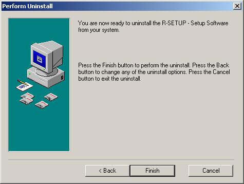
12 2. After select R-Setup - Setup Software, click Change/Remove.(Or click Add/Remove.) The following screen appears and uninstalling starts. 3. The following screen appears. When uninstall all the files that were installed, click Automatic. When select the file to be uninstalled, click Custom and Next >. 4. The following screen appears. When click Finish, uninstalling starts. 10
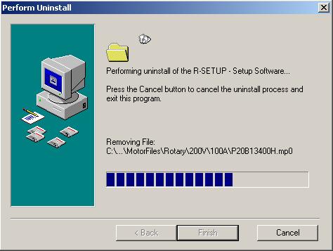
13 5. Uninstalling of the file starts. 11
14 2. Connecting to Servo Amplifier 2.1. Connected Cable Exclusive cable AL CN mm Cable ケーブル長 length CN1 PUSH 6 1 CN1: P-TO-C Without fixed hook (HIROSE ELECTRIC CO., LTD.) CN2:HDEB-9S(50) (Connector HIROSE ELECTRIC CO., LTD.) HDE-CTF(50) (Case HIROSE ELECTRIC CO., LTD.) Note:Connector, case, and cable may be changed into the equivalents without notice. For wiring diagram, see the appendix How to Connect Connect the serial pin (COM) to PC connector of R series servo amplifier with the exclusive cable. 12
15 3. How to Operate 3.1. How to Activate 1. Select Programs - AC_SERVO_SYSTEM in the start menu of Windows task bar. 2. Click R-SETUP. The following start screen appears. R-SETUP Setup Software For Windows(R)95/98/Me,Windows NT(R)4.0,Windows(R)2000/Xp Version Copyright(c)2005 SANYO DENKI CO.,LTD SANYO DENKI CO.,LTD 13

16 3.2. Main Screen After activating R-SETUP Setup Software, the following main screen appears. Each function of R-SETUP Setup Software can be accessed by selecting it in the menu bar of main screen. [File] Exit:Exit R-SETUP - Setup Software. 14
![[Communication] Communication Setting :Set the communication. Possible to select it only at offline.](/docs-images/72/67199033/images/17-0.jpg "Offline->Online :Switch from offline to online and display the confirmation dialog box of communication state. Possible to select it only at offline.")
17 [Communication] Communication Setting :Set the communication. Possible to select it only at offline. Offline->Online :Switch from offline to online and display the confirmation dialog box of communication state. Possible to select it only at offline. Communication Check :Check the communication state. Possible to select it only at online. Online->Offline: Switch from online to offline Possible to select it only at online. Communication Reset : Reset the communication state. (This is used when communication can not be performed. Do not use this usually.) [Parameter] General Parameter Setting :Set and save general parameters of servo amplifiers. System Parameter Setting :Set and save system parameters of servo amplifiers. Motor Parameter Setting :Set and save motor parameters of servo amplifiers. Transmit Parameter [Amplifier->File] :Read all parameters of servo amplifier and save them into amplifier file together. Transmit Parameter [File->Amplifier] :Write the parameters saved in amplifier file into servo amplifier together directly. File Match Parameter (C) (Parameter verification) : Verifies amplifier files conformity, and then shows the verification result list. 15
![[Monitor] Monitor Display :Display a list of state and operation of servo amplifier. Possible to select it only at online.](/docs-images/72/67199033/images/18-1.jpg "Multi-monitor Display :Display a list of state and operation of servo amplifier. Possible to select it only at online. Alarm History Display :Display the alarm history generated in servo amplifier.")
18 [Monitor] Monitor Display :Display a list of state and operation of servo amplifier. Possible to select it only at online. Multi-monitor Display :Display a list of state and operation of servo amplifier. Possible to select it only at online. Alarm History Display :Display the alarm history generated in servo amplifier. [Test Run and Adjustment] Jogging Operation : Run the motor in positive/negative feed at the velocity command set at jogging operation. Possible to select it only at online. Operation for Pulse Feed Jogging : Run the motor in positive/negative feed with the number of feed pulses and movement speed at jogging operation. Possible to select it only at online. Automatic Notch Filter Tuning : Perform automatic notch filter tuning. Possible to select it only at online. Automatic Vibration Suppressor Frequency Tuning : Perform automatic vibration suppressor frequency tuning. Possible to select it only at online. System Analysis : Performs system analysis. Possible to use by selecting complete installation. Fixation Excitation Operation : Perform fixation excitation operation for linear motor. Possible to select it only at online. 16

19 Analog Offset Adjustment of V-REF Terminal : Perform offset adjustment of analog velocity command/torque (force) command. Possible to select it only at online. Analog Offset Adjustment of T-COMP Terminal : Perform offset adjustment of analog torque addition command. Possible to select it only at online. Save Result of Automatic Tuning : Perform save result of automatic tuning function. Possible to select it only at online. Alarm Reset :Reset the current alarm of servo amplifier. Possible to select it only at online. Absolute Encoder Clear : Reset the multi-revolution data of absolute encoder and the alarm in it. Possible to select it only at online. [Trace Operation] Trace Operation :Display and save the trace operation data of servo amplifier. [Help] About :Indicate the information about R-SETUP - Setup Software. 17
 Select COM port. Baud rate Select the communication speed to servo amplifier.")
20 3.3. Communication Setting When select Communication - Communication Setting in the menu bar of main screen, the following screen appears. This sets communication between R-SETUP - Setup Software and servo amplifier through serial port. Port(COM1 to COM256) Select COM port. Baud rate Select the communication speed to servo amplifier. In case of changing the communication speed, change the communication setting of the servo amplifier as well. Axis Number Select Give check mark(s) to the numbered axis of servo amplifier for communication. Multiple selection is possible according to the number of servo amplifiers to be connected. In case of changing the axis number select, change the communication setting of the servo amplifier as well Switching Communication State Offline->Online Select Communication - Offline->Online on the menu bar in the main screen, and the connection of communication cable will be confirmed. If the cable is connected correctly, confirmation dialog box of communication state will be displayed. 18

21 Online->Offline Click Online->Offline during online state, and all the communications with the servo amplifiers currently connected by cables will terminate and switch to offline Communication State Check When select Communication - Offline->Online or Communication Check in the menu bar of main screen, the following dialog box appears after checking the connection of communication cable. Here starts the communication with servo amplifier connected to this cable. In case the communication already starts, update current communication state of servo amplifier. Start the communication as follows. 1. Give the check mark to the numbered axis of servo amplifier for starting communication. Note) As the servo amplifier of numbered axis without check mark in Axis Number Select of Communication Settings can not be used, the check mark can not be given. 2. Click [Check]. 3. Display the servo amplifier state. Contents are as follows. Connected:Now communicating with servo amplifier. Not connected:servo amplifier is not connected. Error:Can not communicate due to communication error. Overlap:The axis number of servo amplifier overlaps. Not-corresponding:The type of servo amplifier differs. Or this can not be corresponded to the software of servo amplifier. Update the R-SETUP - Setup Software version. (R-SETUP cannot be communicated with R series servo amplifier.) 19
22 3.6. General Parameter Setting When select Parameter - General Parameter Setting in the menu bar of main screen, General parameter settings appears. The following can be operated. General parameter setting of servo amplifier General parameter setting of amplifier file Saving the parameters and alarm history of the servo amplifier in the amplifier file together. Writing the parameters from amplifier file to servo amplifier together. Matching the parameters of servo amplifier with that of amplifier file Printing a list of parameters When click [#1] to [#F] on left side of General parameter settings, switch to the setting of corresponding servo amplifier. When click [File], switch to General parameter settings of amplifier file. When click tab of Group* above parameter list, switch the parameter group. Each function of general parameter setting can be accessed by selecting it in the menu bar of General Parameter Setting. 20
![[File] Open :Open the amplifier file to be edited. Possible to select it only when setting parameter of amplifier file. Save:Write the edited amplifier file over a file and save it.](/docs-images/72/67199033/images/23-1.jpg "Possible to select it only when setting parameter of amplifier file. Save As :Save the edited amplifier file in a file as another name.")
23 [File] Open :Open the amplifier file to be edited. Possible to select it only when setting parameter of amplifier file. Save:Write the edited amplifier file over a file and save it. Possible to select it only when setting parameter of amplifier file. Save As :Save the edited amplifier file in a file as another name. Possible to select it only when setting parameter of amplifier file. Exit:Exit General Parameter Settings. [Amplifier] Read from Amplifier:Read the parameters from servo amplifier. Possible to select it only when setting parameter of servo amplifier. Write to Amplifier:Write the edited parameter to servo amplifier. Possible to select it only when setting parameter of servo amplifier. Communication State Check :Check the communication state. Possible to select it only at online. [Disk] Transmit Parameter [Amplifier->File] :Read all parameters and alarm history of servo amplifier and save them in amplifier file together. Possible to select it only when setting parameter of servo amplifier. Transmit Parameter [File->Amplifier] :Directly write the parameters saved in amplifier file to servo amplifier together. Possible to select it only when setting parameter of servo amplifier. 21

24 Match Parameter :Match the parameters of servo amplifier with that of amplifier file and display a list of mismatch parameters. Possible to select it only when setting parameter of servo amplifier. [Print] Print :Print a list of parameters. Print Preview :Display the print image of parameter list Parameter Display Level When click Change of the dialog box of General Parameter Settings,the following dialog box is displayed. Here switch the parameter level displayed in general parameter settings. [Display Level] Basic Level:Display only basic level parameters. Standard Level:Display basic level parameters and standard ones. Advanced Level:Display basic, standard, and advanced level parameters. 22

25 Parameter Setting of Servo Amplifier When displaying the dialog box of general parameter setting at online, the following screen appears and reads the parameters from servo amplifier. When complete reading parameters from servo amplifier correctly, Now Reading disappears and a list of parameters to be set is displayed. When click [Edit ] or double-click with mouse after selecting a parameter to be edited, Edit Parameter is displayed. Depending on parameter classification, the displayed screen changes. Example 1) KP1:When editing Position Loop Proportional Gain 1(Group 1-02) Click tab of Group 1 of parameter setting screen to display a list of parameters of Group 1. When click [Edit ] or double-click with mouse after selecting 02:KP1, the following Edit Parameter screen is displayed. Enter the value to be set in Input Value : by keyboard. 23
![When click [OK], the following message is indicated in case the entered value is outside the setting range. Re-enter the value within the setting range.](/docs-images/72/67199033/images/26-0.jpg "When the entered value is within the setting range, return to parameter setting screen.")
 When editing GER1:Electric Gear Ratio 1(Group 8-15) Click tab of Group 8 of parameter setting screen to display a list of parameters of Group 8.")
26 When click [OK], the following message is indicated in case the entered value is outside the setting range. Re-enter the value within the setting range. When the entered value is within the setting range, return to parameter setting screen. In case the entered value in Input Value is different from Present Value, it is indicated in red. Example 2) When editing GER1:Electric Gear Ratio 1(Group 8-15) Click tab of Group 8 of parameter setting screen to display a list of parameters of Group 8. When click [Edit ] or double-click with mouse after selecting 15:GER1, the following Edit Parameter screen is displayed. Enter the numerator and denominator in Input Value : by keyboard. 24
27 When the entered value is within the setting range, return to parameter setting screen. In case the entered value in Input Value is different from Present Value, it is indicated in red. Example 3) MON1:When editing Analog Monitor 1, Output Signal Selection (Group A-11) Click tab of Group A of parameter setting screen to display a list of parameters of Group A. When click Edit or double-click with mouse after selecting 11:MON1, the following Edit Parameter screen is displayed. Select the value to be set in the combo box. 25


28 Note) When set the value outside the setting range, only Reserve is indicated in combo box. In this case, the value can not be changed. When click [OK],return to parameter setting screen. In case the selected value in Input Value is different from Present Value, it is indicated in red. The parameters in one group can be edited together. After completing editing parameters, select Amplifier - Write to Amplifier in the menu bar of parameter setting screen. The following screen appears and writes the parameters to servo amplifier. 26
29 When complete writing parameters to servo amplifier correctly, Now writing disappears. The value in Input Value disappears and indicates the value entered in Present Value. Note) If click another Group before writing to servo amplifier or switch to the setting of another servo amplifier or amplifier file after editing parameters, the following dialog box is displayed. When click [Yes], switch the display to another Group or another servo amplifier after writing the edited parameters to servo amplifier which is now communicating. When click [No], switch the display to another Group or another servo amplifier without writing the edited parameters. The entered value is cancelled. When click [Cancel], switch to another Group or another servo amplifier is not conducted. 27
30 Parameter Setting of Amplifier File When display general parameter setting screen at offline or click [File], the following screen is displayed. Here the saved parameters of amplifier file can be set. When select File - Open in the menu bar of general parameter, the following file selection dialog box is displayed. Select the amplifier file to be set and click [Open]. Display a list of parameters to be set. 28
31 Edit parameters as well as that of servo amplifier. After completing editing parameters, select File - Save in the menu bar of parameter setting screen and save the edited parameters in amplifier file. When save the edited parameters in another file which is different from the amplifier file which is now running, select File - Save As in the menu bar. The following dialog box of saving file is displayed. Specify the space and name of file and click [Save]. Save the amplifier file as a new name. Note) If click another Group before saving in amplifier file or switch to the setting of another servo amplifier after editing parameters, the following dialog box is displayed. 29
32 When click [Yes], the display is switched to another Group or another servo amplifier after saving the edited parameters to servo amplifier which is now running. When click [No], the display is switched to another Group or another servo amplifier without saving the edited parameters. The entered value is cancelled. When click [Cancel], switch to another Group or another servo amplifier is not conducted Transmit Parameter [Amplifier->File] Transmit Parameter [Amplifier->File] reads all parameters and alarm history of servo amplifier and save them in amplifier file together. In this case, the parameters are directly saved in the disk without displaying them. For operation, see 3.9. Transmit Parameter [Amplifier->File] Transmit Parameter [File->Amplifier] Transmit Parameter [File->Amplifier] directly writes the parameters saved in amplifier file to servo amplifier together. For operation, see Transmit Parameter [File->Amplifier] Match Parameter Match Parameter matches the parameters of servo amplifier with that of amplifier file and indicates a list of mismatches if applicable. When select Amplifier - Match Parameter in the menu bar of general parameter setting, the following selection dialog box appears. 30
33 Select the amplifier file to be matched with servo amplifier and click [Open]. When software version of servo amplifier is different from that of amplifier file or hardware differs, the following dialog box is displayed. The Servo amplifier software version of the transmission source having saved the amplifier file and that of transmission destination are different, or those hardware types are different. For this reason, non-compatible parameter may exist. Click Yes, and match parameter starts including the incompatible parameters. Those incompatible parameters, regardless of its setting values, will be indicated their names in red as not matching Click Cancel, matching parameters are not conducted. Note) In case this dialog box appears according to the difference of software version. There may be some parameters without interchangeability depending on the software version. Those without interchangeability are indicated in matching results (contents of difference) regardless of their setting. Here, the parameters are indicated in red as well. Note) In case this dialog box appears according to the difference of hardware type. There may be some parameters without interchangeability because of the difference of encoder interface circuit. Those without interchangeability are indicated in matching results (contents of difference) regardless of their setting. Take care in using multiple hardware servo amplifiers. In case that the classification of servo amplifier is different from that of amplifier file, the following dialog box appears and matching parameters cannot be conducted. 31


34 When parameter matching starts, read the parameters from servo amplifier. When complete reading parameters from servo amplifier correctly, Now Reading disappears and parameter matching process starts. When completing parameter matching process, Now Processing disappears and the following list of parameter matching result is displayed. If match parameters in case that the software version of servo amplifier is different from that of amplifier file, other kinds of parameters are displayed. The parameters are displayed all in red. When click [Print], print a list of parameters being displayed. 32
35 3.7. System Parameter Setting When select Parameter - System Parameter Setting in the menu bar of main screen, System parameter settings appears. The following can be operated. System parameter setting of servo amplifier System parameter setting of amplifier file Saving the parameters of servo amplifier in amplifier file together Writing the parameters from amplifier file to servo amplifier together. Matching the parameters of servo amplifier with that of amplifier file Printing a list of parameters When click [#1] to [#F] on left side of System parameter settings, switch to the setting of corresponding servo amplifier. When click [File], switch to System parameter settings of amplifier file. Each function of system parameter setting can be accessed by selecting it in the menu bar of System Parameter Settings. 33
![[File] Open :Open the amplifier file to be edited. Possible to select it only when setting parameter of amplifier file. Save:Write the edited amplifier file over a file and save it.](/docs-images/72/67199033/images/36-0.jpg "Possible to select it only when setting parameter of amplifier file. Save As :Save the edited amplifier file in a file as another name.")
![Possible to select it only when setting parameter of amplifier file. Exit:Exit System Parameter Settings. [Amplifier] Read from Amplifier:Read the parameters from servo amplifier.](/docs-images/72/67199033/images/36-2.jpg "Possible to select it only when setting parameter of servo amplifier. Write to Amplifier:Write the edited parameter to servo amplifier.")
36 [File] Open :Open the amplifier file to be edited. Possible to select it only when setting parameter of amplifier file. Save:Write the edited amplifier file over a file and save it. Possible to select it only when setting parameter of amplifier file. Save As :Save the edited amplifier file in a file as another name. Possible to select it only when setting parameter of amplifier file. Exit:Exit System Parameter Settings. [Amplifier] Read from Amplifier:Read the parameters from servo amplifier. Possible to select it only when setting parameter of servo amplifier. Write to Amplifier:Write the edited parameter to servo amplifier. Possible to select it only when setting parameter of servo amplifier. Communication State Check :Check the communication state. Possible to select it only at online. [Disk] Transmit Parameter [Amplifier->File] :Read all parameters from servo amplifier and save them in amplifier file together. Possible to select it only when setting parameter of servo amplifier. Transmit Parameter [File->Amplifier] :Directly write the parameters saved in amplifier file to servo amplifier together. Possible to select it only when setting parameter of servo amplifier. 34

37 Match Parameter :Match the parameters of servo amplifier with that of amplifier file and display a list of mismatch parameters. Possible to select it only when setting parameter of servo amplifier. [Print] Print :Print a list of parameters. Print Preview :Display the print image of parameter list Parameter Setting of Servo Amplifier When displaying the dialog box of general parameter setting at online, the following screen appears and reads the parameters from servo amplifier. When complete reading parameters from servo amplifier correctly, Now Reading disappears and a list of parameters to be set is displayed. When click [Edit ] or double-click with mouse after selecting a parameter to be edited, parameter editing screen is displayed. Depending on parameter classification, the displayed screen changes. For parameter editing, see Parameter setting of servo amplifier 35

38 After parameter editing, select Amplifier - Write to Amplifier in the menu bar of parameter setting screen. The following dialog box appears. When click OK, the parameters are written to servo amplifier. When click Cancel, the parameters are not written. When complete writing parameters to servo amplifier correctly, Now writing disappears. The value in Input Value disappears and indicates the value entered in Present Value. Note) If click another Group before writing to servo amplifier or switch to the setting of another servo amplifier or amplifier file after editing parameters, the following dialog box is displayed. When click [Yes], the display is switched to another Group or another servo amplifier after writing the edited parameters to servo amplifier which is currently communicating. When click [No], the display is switched to another Group or another servo amplifier without writing the edited parameters. The entered value is cancelled. 36
![3.7.2. Parameter Setting of Amplifier File When display System parameter setting screen at offline or click [File], the following screen is displayed.](/docs-images/72/67199033/images/39-0.jpg "Here the saved parameters of amplifier file can be set. When select File - Open in the menu bar of System parameter setting, the following file selection dialog box is displayed.")
39 Parameter Setting of Amplifier File When display System parameter setting screen at offline or click [File], the following screen is displayed. Here the saved parameters of amplifier file can be set. When select File - Open in the menu bar of System parameter setting, the following file selection dialog box is displayed. Select the amplifier file to be set and click [Open]. Display a list of parameters to be set. 37

40 Edit parameters as well as that of servo amplifier. After parameter editing, select File - Save in the menu bar of parameter setting screen. The following dialog box appears. When click [OK] to save the edited parameters in amplifier file. When click [Cancel], the parameters are not saved. When save the edited parameters in another file which is different from the amplifier file which is now running, select File - Save As in the menu bar. The following dialog box of saving file is displayed. Specify the space and name of file and click [Save]. Save the amplifier file as a new name. 38
41 Note) If click another Group before saving in amplifier file or switch to the setting of another servo amplifier after editing parameters, the following dialog box is displayed. When click [Yes], the display is switched to another servo amplifier after saving the edited parameters to servo amplifier which is now running. When click [No], the display is switched to another servo amplifier without saving the edited parameters. The entered value is cancelled. When click [Cancel], switch to another servo amplifier is not conducted Transmit Parameter [Amplifier->File] Transmit Parameter [Amplifier->File] reads all parameters of servo amplifier and save them in amplifier file together. In this case, the parameters are directly saved in the disk without displaying them. For operation, see 3.9. Transmit Parameter [Amplifier->File] Transmit Parameter [File->Amplifier] Transmit Parameter [File->Amplifier] directly writes the parameters saved in amplifier file to servo amplifier together. For operation, see Transmit Parameter [File->Amplifier] Match Parameter Match Parameter matches the parameters of servo amplifier with that of amplifier file and indicates a list of mismatches if applicable. For operation, see Match parameter. 39
42 3.8. Motor Parameter Setting When select Parameter - Motor parameter Setting in the menu bar of main screen, Motor parameter settings appears. The following can be operated. Motor parameter setting of servo amplifier Motor parameter setting of amplifier file Saving the parameters of servo amplifier in amplifier file together Writing the parameters from amplifier file to servo amplifier together. Matching the parameters of servo amplifier with that of amplifier file Printing a list of parameters When click [#1] to [#F] on left side of Motor parameter settings, switch to the setting of corresponding servo amplifier. When click [File], switch to Motor parameter settings of amplifier file. Each function of motor parameter setting can be accessed by selecting it in the menu bar of Motor Parameter Settings. 40
![[File] Open :Open the amplifier file to be edited. Possible to select it only when setting parameter of amplifier file. Save:Write the edited amplifier file over a file and save it.](/docs-images/72/67199033/images/43-0.jpg "Possible to select it only when setting parameter of amplifier file. Save As :Save the edited amplifier file in a file as another name.")
43 [File] Open :Open the amplifier file to be edited. Possible to select it only when setting parameter of amplifier file. Save:Write the edited amplifier file over a file and save it. Possible to select it only when setting parameter of amplifier file. Save As :Save the edited amplifier file in a file as another name. Possible to select it only when setting parameter of amplifier file. Exit:Exit Motor Parameter Settings. [Amplifier] Read from Amplifier:Read the parameters from servo amplifier. Possible to select it only when setting parameter of servo amplifier. Write to Amplifier:Write the edited parameter to servo amplifier. Possible to select it only when setting parameter of servo amplifier. Communication State Check :Check the communication state. Possible to select it only at online. [Disk] Transmit Parameter [Amplifier->File] :Read all parameters of servo amplifier and save them in amplifier file together. Possible to select it only when setting parameter of servo amplifier. Transmit Parameter [File->Amplifier] :Directly write the parameters saved in amplifier file to servo amplifier together. Possible to select it only when setting parameter of servo amplifier. 41

44 Match Parameter :Match the parameters of servo amplifier with that of amplifier file and display a list of mismatch parameters. Possible to select it only when setting parameter of servo amplifier. [Print] Print :Print a list of parameters. Print Preview :Display the print image of parameter list Parameter Setting of Servo Amplifier When displaying the dialog box of Motor parameter setting at online, the following screen appears and reads the parameters from servo amplifier. When complete reading parameters from servo amplifier correctly, Now Reading disappears and a list of parameters to be set is displayed. When click [Motor select from list ] or double-click the field of Motor Setting, a dialog box of motor selection appears. 42
![Select the motor parameter file which writes to servo amplifier in the list. When click [OK], return to parameter setting screen.](/docs-images/72/67199033/images/45-0.jpg "When the model name of selected motor is different from Present Value, the model name is indicated in Input Value in red.")

45 Select the motor parameter file which writes to servo amplifier in the list. When click [OK], return to parameter setting screen. When the model name of selected motor is different from Present Value, the model name is indicated in Input Value in red. After parameter editing, select Amplifier - Write to Amplifier in the menu bar of parameter setting screen. The following dialog box appears. When click [OK], the parameters are written to servo amplifier. When click [Cancel], the parameters are not written. 43
 If click another Group before writing to servo amplifier or switch to the setting of another servo amplifier or amplifier file after editing parameters, the following dialog box is displayed.")
46 When complete writing parameters to servo amplifier correctly, Now writing disappears. The value in Input Value disappears and indicates the value entered in Present Value. Note) If click another Group before writing to servo amplifier or switch to the setting of another servo amplifier or amplifier file after editing parameters, the following dialog box is displayed. When click [Yes], the display is switched to another servo amplifier after writing the edited parameters to servo amplifier which is currently communicating. When click [No], the display is switched to another servo amplifier without writing the edited parameters. The entered value is cancelled. When click [Cancel], switch to another servo amplifier is not conducted. 44
47 Parameter Setting of Amplifier File When display General parameter setting at offline or click [File], the following screen is displayed. Here the saved parameters of amplifier file can be set. When select File - Open in the menu bar of System parameter setting, the following file selection dialog box is displayed. Select the amplifier file to be set and click [Open]. Display a list of parameters to be set. 45

48 Edit parameters as well as that of servo amplifier. After parameter editing, select File - Save in the menu bar of parameter setting screen. The following dialog box appears. When click [OK] to save the edited parameters in amplifier file. When click [Cancel], the parameters are not saved. When save the edited parameters in another file which is different from the amplifier file which is now running, select File - Save As in the menu bar. The following screen of saving file is displayed. Specify the space and name of file and click [Save]. Save the amplifier file as a new name. 46

49 Note) If click another Group before saving in amplifier file or switch to the setting of another servo amplifier after editing parameters, the following dialog box is displayed. When click [Yes], the display is switched to another servo amplifier after saving the edited parameters to servo amplifier which is currently running. When click [No], the display is switched to another servo amplifier without saving the edited parameters. The entered value is cancelled. When click [Cancel], switch to another servo amplifier is not conducted Transmit Parameter [Amplifier->File] Transmit Parameter [Amplifier->File] reads all parameters of servo amplifier and save them in amplifier file together. In this case, the parameters are directly saved in the disk without displaying them. For operation, see 3.9. Transmit Parameter [Amplifier->File] Transmit Parameter [File->Amplifier] Transmit Parameter [File->Amplifier] directly writes the parameters saved in amplifier file to servo amplifier together. For operation, see Transmit Parameter [File->Amplifier] Match Parameter Match Parameter matches the parameters of servo amplifier with that of amplifier file and indicates a list of mismatches if applicable. For operation, see Match parameter. 47
50 3.9. Transmit Parameter [Amplifier->File] Transmit Parameter [Amplifier->File] reads all parameters of servo amplifier and save them in amplifier file together. In this case, the parameters are directly saved in the disk without displaying them. When select Parameter - Transmit Parameter [Amplifier->File] in the menu bar of main screen or select Amplifier - Transmit Parameter [Amplifier->File] in the menu bar of General parameter settings / System parameter settings / Motor parameter settings, the following appears. Transmit the parameters and alarm history from servo amplifier to amplifier file referring to the following procedure. 1. Select the axis number of servo amplifier which transmits parameters in Transmission source. 2. When click [Browse ] in Transmission destination, the following dialog box of saving file appears. 48
51 Specify the space and name of a file and click Save. 3. When click [Execute], the following appears and reads parameters and alarm history from servo amplifier. 4. When complete reading parameters and alarm history to servo amplifier correctly, "Now reading" disappears and "The completion" appears. The read parameters and alarm history are saved in amplifier file Transmit Parameter [File->Amplifier] Transmit Parameter [File->Amplifier] directly writes the parameters saved in amplifier file to servo amplifier together. When select Parameter - Transmit Parameter [File->Amplifier] in the menu bar of main screen or select Amplifier - Transmit Parameter [File->Amplifier] in the menu bar of General parameter settings / System parameter settings / Motor parameter settings, the following appears. 49
52 Transmit the parameters from servo amplifier to amplifier file as the following procedure. 1. Select the axis number of servo amplifier which transmits parameters in Transmission destination. 2. When click [Browse ] in Transmission source, the following dialog box of saving file appears. Select the amplifier file which writes to servo amplifier together and click [Open]. 3. Select the class of parameter which is written to servo amplifier in The kind of parameter to transmit. 4. When click [Execute], the following dialog box appears. When click [OK], the parameters are written to servo amplifier together. 50


53 In case the software version of servo amplifier is different from that of amplifier file or hardware differs, the following dialog box appears. The Servo amplifier software version of the transmission source having saved the amplifier file and that of transmission destination are different, or those hardware types are different. Thus, the part of incompatible parameters may not be transmitted. Click Yes, and the transmission will be executed except for the incompatible parameters. After the transmission is completed, check the parameters that have not been transmitted by Match parameter. Set up those parameters in manual if necessary. (For operation, see Match parameter.) Click No, parameters are not transmitted. 51
54 When the kind of servo amplifier is different from that of amplifier file, parameters are not written together as the following dialog box. 5. When complete writing together correctly, Now Writing disappears and The completion appears. 52


55 3.11. Verification of parameter file Selecting File Match Parameter from Parameter on the menu bar of main screen displays File Match Parameter window, a parameter verification window. With this window, you can verify parameter files conformity. ( ファイル同士が適合するかを照合できる の意味です ) To display this window, select File Match Parameter from Parameter on the menu bar of main screen. Selecting a box of File 1 in File Match Parameter window, the flowing file selecting dialog box is displayed. Click Open after selecting file you want to verify. Select a box same way. of File 2 in the 53
56 If there is a difference between the software versions or hardware you selected to verify their conformity, the following dialog is displayed. Clicking OK initiates parameter verification. Clinking Cancel does not perform verification. Note) When this dialog displayed, several incompatible parameters may exist depending on software versions. Any incompatible parameters are displayed in verification result (differences) list, regardless of the setting contents. The incompatible parameters names are also displayed in red. Note) When this dialog is displayed due to hardware difference. Several incompatible parameters may exist due to hardware difference, such as difference of encoder interface circuit. Any incompatible parameters are displayed in a verification result (differences) list, regardless of the setting contents. Please carefully operate servo amplifier with multiple hardware in regard to this point. The following dialog is displayed and then no parameter verification can be performed if different types of servo amplifiers exist between amplifier files. 54

57 When parameter verification process completed, the following parameter verification result list is displayed. If any differences in software version, but verification have been performed, different kind of parameters is displayed all in red. Clicking Print starts printing a list of parameters being displayed. 55

58 3.12. Monitor Display When click Monitor - Monitor Display in the menu bar of main screen, the following screen appears. Here display a list of the status and operation of servo amplifier which is currently connected by the cable. When click [#1] to [#F] on the left side of Monitor Display, the status of corresponding servo amplifier which is numbered is displayed in monitor. Each function of Monitor display can be accessed by selecting it in the menu bar of Monitor Display. [File] Exit:Exit Monitor Display. 56
59 3.13. Multi-monitor Display When click Monitor - Multi-monitor Display in the menu bar of main screen, the following screen appears. Here displays 16 cases at maximum in the status and operation of servo amplifier which is currently connected by the cable. Each function of Multi-monitor display can be accessed by selecting it in the menu bar of Multi-monitor Display. [File] Exit:Exit Multi-monitor Display. 57
 on either one(s) from No. 0 to No.")
60 Multi-monitor Display Setting When click Display Setting in multi-monitor display screen, the following screen appears. The parameters performing monitor display in multi-monitor display are selected in the servo amplifier which is currently connected. Give check mark(s) on either one(s) from No. 0 to No. 15 in which multi-monitor display is desired to select axis number and display parameter. 58

61 3.14. Alarm History When click Monitor - Alarm History Display in the menu bar of main screen, the following screen appears. Here displays an alarm history generated in servo amplifier which is currently connected by a cable. When click [#1] to [#F] in the left of Alarm History Display, the alarm of the corresponding numbered servo amplifier is displayed. When click [File], switch to Alarm History saved in amplifier file. In order to save the information of servo amplifier alarm history in a file, execute Transmit Parameter [Amplifier->File]. Refer to 3.9 Transmit Parameter [Amplifier->File] for the procedure. Current State Display the alarm which is currently generated, the state of servo amplifier (current state in case of No alarm ), and the passed time from generating. Alarm Generating History Display last seven alarms. This history is updated at any time. Software Version of Servo Amplifier Display the software version of servo amplifier. Each function of alarm history display can be accessed by selecting it in the menu bar of Alarm History Display. 59
![[File] Open :Open an amplifier file displaying alarm history. Possible to select it only at displaying an alarm history of amplifier file. Exit:Exit Alarm History Display.](/docs-images/72/67199033/images/62-0.jpg "[Amplifier] Alarm Reset:Reset the current alarm of servo amplifier. Possible to select it only at displaying an alarm history of servo amplifier.")
62 [File] Open :Open an amplifier file displaying alarm history. Possible to select it only at displaying an alarm history of amplifier file. Exit:Exit Alarm History Display. [Amplifier] Alarm Reset:Reset the current alarm of servo amplifier. Possible to select it only at displaying an alarm history of servo amplifier. Alarm Trace Clear:Clear the servo amplifier s data of alarm which was generated in the past. Possible to select it only at displaying an alarm history of servo amplifier. [Print] Print :Print a list of alarm history. Print Preview :Display the print image of parameter list Alarm Reset For Alarm Reset, reset the current alarm of servo amplifier. For how to operate, see Alarm Reset Alarm Trace Clear For Alarm Trace Clear, clear the servo amplifier s data of alarm which was generated in the past. Refer to Alarm Trace Clear for the procedure. 60
63 3.15. Jogging Operation Jogging operation can test the servo amplifier and servomotor easily. This function runs the servomotor. Secure the safety of the surroundings. When the alarm generates during jogging operation, motor excitation becomes OFF. Prepare the control equipments which can be readily used. When select Test Run and Adjustment - Jogging operation in the menu bar of main screen, the following appears. Here runs the motor in positive/negative directions with the velocity command set by jogging operation. Jogging operation is performed as follows. 1. Select the axis number of servo amplifier performing jogging operation in Select Servo Amplifier. 2. When click Execute, the following appears. For the servo amplifier which jogging operation is not functioned, the following dialog box appears when click OK. This servo amplifier can not use jogging operation. 61

64 When servo amplifier is not ready, the following dialog box appears. Jogging operation is not ready. In caser servo amplifier is in alarm state, main power is not supplied, or Test Run and Adjustment is executed with digital operator, jogging operation is not ready. When confirming that jogging operation can be used, click Execute again. In case servo amplifier is ready, the following appears. 3. Select the operation at completing and set the jogging velocity command. When generate Alarm of Test Run complete at completing jogging operation, click At completing, Alarm of Test Run complete is selected. In case of the opposite, click At completing, Alarm of Test Run complete is not selected. When changing jogging velocity command, click Edit and switch to editing mode. Enter the value in keyboards and click Write. 4. In case of generating alarm, the following dialog box appears when click Servo ON. 62
65 In case servo amplifier can not function Servo ON, the following dialog box appears. When confirming that Servo ON can be used, click Servo ON again. In case of Servo ON, Positive move and Negative move buttons can be used. While editing velocity command, Positive move and Negative move buttons can not be used. After click Write, complete the editing. 5. While continue to click Positive move or Negative move, jogging operation is being executed. While Over-travel is confirmed, the following dialog box appears. 63
66 While editing velocity command, the following appears. When click Write, complete the editing by updating the set value. When click Edit Cancel, complete the editing without updating the set value. 64
67 3.16. Operation for Pulse Feed Jogging Operation for Pulse Feed Jogging can test the servo amplifier and servomotor easily. This function runs the servomotor. Secure the safety of the surroundings. When the alarm generates during operation for feed Jogging operation, motor excitation becomes OFF. Prepare the control equipments which can be readily used. When select Test Run and Adjustment - Operation for Pulse Feed Jogging in the menu bar of main screen, the following appears. Here runs the motor in positive/negative directions with the number of feed pulses and movement speed set by jogging operation. Operation for pulse feed jogging is performed as follows. 1. Select the axis number of servo amplifier performing jogging operation in Select Servo Amplifier. 2. When click Execute, the following appears. For the servo amplifier which pulse feed jogging operation is not functioned, the following dialog box appears when click OK. This servo amplifier can not use jogging operation. 65
68 When servo amplifier is not ready, the following dialog box appears. Jogging operation is not ready. In case servo amplifier is in alarm state, main power is not supplied, or Test Run and Adjustment is executed with digital operator, jogging operation is not ready. When confirming that jogging operation can be used, click Execute again. In case servo amplifier is ready, the following appears. 3. Select the operation at completing and set the number of feed pulses and movement speed. When generate Alarm of Test Run complete at completing pulse feed jogging operation, click At completing, Alarm of Test Run complete is selected. In case of the opposite, click At completing, Alarm of Test Run complete is not selected. When changing the number of feed pulses and movement speed, click Edit and switch to editing mode. Enter the value in keyboards and click Write. 66

69 4. In case of generating alarm, the following dialog box appears when click Servo ON. In case servo amplifier can not function Servo ON, the following dialog box appears. In case of Servo ON, Positive move and Negative move buttons can be used. In case of Servo ON, Positive Feed, Negative Feed, and Stop & Deviation Clear buttons are enabled. While editing the number of feed pulses and movement speed, Positive Feed, Negative Feed, and Stop & Deviation Clear buttons can not be used. After click Write, complete the editing. 5. When click Positive feed or Negative feed, move the number of feed pulses to be set. In case of stopping before moving the number of feed pulses to be set, click Stop & Deviation Clear. 67
70 While Over-travel is confirmed, the following dialog box appears. When the setting of number of feed pulses or movement speed is inadequate, the following appears. Change the setting. While editing the number of feed pulses or movement speed, the following appears. When click Write, complete the editing by updating the set value. When click Edit Cancel, complete the editing without updating the set value. 68
71 3.17. Automatic Notch Filter Tuning Automatic notch filter tuning can readily find the resonance frequency by running servo amplifier and servomotor for a short period. In case resonance frequency exists, set the frequency at command notch filter A (TCNFILA) automatically. This function runs the servomotor. Secure the safety of surroundings. During execution, the holding torque becomes small. At the weight axis and so on, do not use this function. When select Test Run and Adjustment - Automatic Notch Filter Tuning in the menu bar of main screen, the following appears. Here executes automatic notch filter tuning. Automatic notch filter tuning is performed as follows. 1. Select the axis number of servo amplifier performing automatic notch filter tuning in Select Servo Amplifier. 2. When click Execute, the following appears. For the servo amplifier which automatic notch filter tuning is not functioned, the following dialog box appears when click OK. This servo amplifier can not perform automatic notch filter tuning. 69
72 When servo amplifier is not ready, the following dialog box appears. Automatic notch filter tuning is not ready. In case servo amplifier is in alarm state, main power is not supplied, or Test Run and Adjustment is executed with digital operator, tuning operation is not ready. When confirming that automatic notch filter tuning can be used, click Execute again. In case servo amplifier is ready, the following appears. 3. Select the operation at completing and set the torque command value of tuning. When generate Alarm of Test Run complete at completing automatic notch filter tuning, click At completing, Alarm of Test Run complete is selected. In case of the opposite, click At completing, Alarm of Test Run complete is not selected. When changing the torque command value of tuning, click Edit and switch to editing mode. Enter the value in keyboards and click Write. 70
73 4. In case of generating alarm, the following dialog box appears when click Servo ON. In case servo amplifier can not function Servo ON, the following dialog box appears. In case of Servo ON, Execute, button is enabled. While editing torque command value, Execute button can not be used. After click Write, complete the editing. 5. When click Execute, the following appears and execute automatic notch filter tuning. 71
 Command, Notch Filter A (TCNFILA).")

74 6. When automatic notch filter tuning completes normally, Execute disappears and the following dialog box of tuning result appears. This tuning result is saved in Torque (Force) Command, Notch Filter A (TCNFILA). When automatic notch filter tuning can not complete normally, the following dialog box appears. During editing torque command, the following appears. When click Write, complete the editing by updating the setting value. When click Edit Cancel, complete the editing without updating the setting value. 72
75 3.18. Automatic Vibration Suppressor Frequency Tuning Automatic Vibration Suppressor Frequency Tuning can easily set the vibration suppressor control parameter Vibration Suppressor Frequency 1 (SUPFRQ1) by running servo amplifier and servomotor for a short period. After the tuning is executed, the result is automatically set to Vibration Suppressor Frequency 1 (SUPFRQ1). This function runs the servomotor. Secure the safety of surroundings. During execution, the holding torque becomes small. At the weight axis and so on, do not use this function. When select Test Run and Adjustment - Automatic Vibration Suppressor Frequency Tuning in the menu bar of main screen, the following appears. Here executes Automatic Vibration Suppressor Frequency Tuning. Automatic Vibration Suppressor Frequency Tuning is performed as follows. 1. Select the axis number of servo amplifier performing automatic vibration suppressor frequency tuning in Select Servo Amplifier. 2. When click Execute, the following appears. For the servo amplifier which automatic vibration suppressor frequency tuning is not functioned, the following dialog box appears when click OK. This servo amplifier can not perform automatic vibration suppressor frequency tuning. 73
76 When servo amplifier is not ready, the following dialog box appears. Automatic Vibration Suppressor Frequency Tuning is not ready. In case servo amplifier is in alarm state, main power is not supplied, or Test Run and Adjustment is executed with digital operator, tuning operation is not ready. When confirming that automatic vibration suppressor frequency tuning can be used, click Execute again. In case servo amplifier is ready, the following appears. 3. Select the operation at completing and set the torque (force) command and friction torque (force) compensation value of tuning. When generate Alarm of Test Run complete at completing automatic vibration suppressor frequency tuning, click At completing, Alarm of Test Run complete is selected. In case of the opposite, click At completing, Alarm of Test Run complete is not selected. When changing the torque (force) command and friction torque (force) value of tuning, click Edit and switch to editing mode. Enter the value in keyboards and click Write. 74


77 4. In case of generating alarm and servo amplifier can not function Servo ON, the following appears. In case of Servo ON, Execute, button is enabled. While editing torque (force) command and friction torque (force) compensation value, Execute button can not be used. After click Write, complete the editing. 5. When click Execute, the following appears and execute automatic vibration suppressor frequency tuning. In auto vibration suppression frequency tuning, the motor operates for maximum of 30 seconds. If [Cancel] is click, tuning can be interrupted with servo-on. 75
. When automatic vibration suppressor frequency tuning can not complete normally, the following dialog box appears.")
78 6. When automatic vibration suppressor frequency tuning completes normally, Execute disappears and the following dialog box of tuning result appears. This tuning result is saved in Vibration Suppressor Frequency 1 (SUPFRQ1). When automatic vibration suppressor frequency tuning can not complete normally, the following dialog box appears. During editing torque (force) command and friction torque (force) compensation, the following appears. When click Write, complete the editing by updating the setting value. When click Edit Cancel, complete the editing without updating the setting value. 76

79 3.19. Fixation Excitation Operation This functions fixation excitation operation for linear motor. This function runs servomotor. Secure the safety of surroundings. When select Test Run and Adjustment - Fixation Excitation Operation in the menu bar of main screen, the following appears. Here executes fixation excitation operation for linear motor. Fixation Excitation Operation is performed as follows. 1. Select the axis number of servo amplifier performing fixation excitation operation in Select Servo Amplifier. 2. When click Execute, the following appears. For the servo amplifier which fixation excitation operation is not functioned, the following dialog box appears when click OK. This servo amplifier can not execute fixation excitation operation. 77

80 When servo amplifier is not ready, the following dialog box appears. Fixation Excitation Operation is not ready. In case servo amplifier is in alarm state, main power is not supplied, or Test Run and Adjustment is executed with digital operator, jogging operation is not ready. When confirming that fixation excitation operation can be used, click Execute again. When servo amplifier is ready, the following dialog box appears and execute fixation excitation operation. When click Cancel, fixation excitation operation is cancelled. 3. When fixation excitation operation completes normally, Now executing disappears and the following dialog box appears. When fixation excitation operation can not complete normally, the following dialog box appears. 78
 in the menu bar of main screen, the following appears.")
81 3.20. Automatic Offset Adjustment of V-REF Terminal This is the function for offset adjustment of analog velocity command input terminal (V-REF). When select Test Run and Adjustment - Automatic Offset Adjustment (V-REF) in the menu bar of main screen, the following appears. Here performs automatic offset adjustment of analog velocity command/torque command. Automatic offset adjustment of analog velocity command/torque command is performed as follows. 1. Select the axis number of servo amplifier performing automatic offset adjustment of analog velocity command/torque command in Select Servo Amplifier. 2. When click Execute, the following appears. For the servo amplifier which automatic offset adjustment of analog velocity command/torque command is not functioned, the following dialog box appears when click OK. This servo amplifier can not execute automatic offset adjustment of analog velocity command/torque command. 79
82 When servo amplifier is not ready, the following dialog box appears. Automatic offset adjustment of analog velocity command/torque command is not ready. In case Test Run and Adjustment is executed with digital operator, automatic offset adjustment of analog velocity command/torque command is not ready. When confirming that automatic offset adjustment of analog velocity command/torque command is enabled, click Execute again. When servo amplifier is ready, the following dialog box appears and executes automatic offset adjustment of analog velocity command/torque command. 3. When automatic offset adjustment of analog velocity command/torque command completes normally, Now executing disappears and the following dialog box appears. When automatic offset adjustment of analog velocity command/torque command can not complete normally, the following dialog box appears. 80
 in the menu bar of main screen, the following appears.")
83 3.21. Automatic Offset Adjustment of T-COMP Terminal This is the function for offset adjustment of analog torque addition command input terminal (T-COMP). When select Test Run and Adjustment - Automatic Offset Adjustment (T-COMP) in the menu bar of main screen, the following appears. Here performs automatic offset adjustment of analog torque addition command. Automatic offset adjustment of analog torque addition command is performed as follows. 1. Select the axis number of servo amplifier performing automatic offset adjustment of analog torque addition command in Select Servo Amplifier. 2. When click Execute, the following appears. For the servo amplifier which automatic offset adjustment of analog torque addition command is not functioned, the following dialog box appears when click OK. This servo amplifier can not execute automatic offset adjustment of analog torque addition command. When servo amplifier is not ready, the following dialog box appears. 81
84 Automatic offset adjustment of analog torque addition command is not ready. In case Test Run and Adjustment is executed with digital operator, automatic offset adjustment of analog velocity command/torque command is not ready. When confirming that automatic offset adjustment of analog torque addition command is enabled, click Execute again. When servo amplifier is ready, the following dialog box appears and execute automatic offset adjustment of analog torque addition command. 3. When automatic offset adjustment of analog torque addition command completes normally, Now executing disappears and the following dialog box appears. When automatic offset adjustment of analog torque addition command can not complete normally, the following dialog box appears. 82
85 3.22. Save Result of Automatic Tuning This is the function for saving control gain that automatic tuning function outputs. The control gain are saved as the parameter. Five kinds of parameters are saved. Position Loop Proportional Gain 1 (KP1) Velocity Loop Proportional Gain 1 (KVP1) Velocity Loop Integral Time Constant 1 (TVI1) Torque (Force) Command Filter 1 (TCFIL1) Load Inertia Ratio (Load Mass Ratio) 1 (JRAT1) The saved contents are different according to the setting of Tuning Mode (TUNMODE) and Automatic Tuning Characteristic (ATCHA). Setting value of Tuning Function Parameter Name Group0-Page00 TUNMODE Tuning Mode Group0-Page01 ATCHA Automatic Tuning Characteristic 00:_Positioning1 01:_Positioning2 02:_Positioning3 03:_Trajectory1 Setting value / Parameter Monitor Value of Automatic Tuning (Saving Contents) 00:_AutoTun 01:_AutoTun_JRAT-Fix 02:_ManualTun 04:_Trajectory2 00:_Positioning1 01:_Positioning2 02:_Positioning3 03:_Trajectory1 04:_Trajectory2 00:_Positioning1 01:_Positioning2 02:_Positioning3 03:_Trajectory1 04:_Trajectory2 Parameter Monitor Value of Automatic Tuning (Saving Contents) KP Parameter KP1 setting value KVP control gain that control gain that TVI automatic tuning automatic tuning function outputs function outputs TCFIL (Note 1) (Note 1) JRAT Remarks Control gain corresponding to parameter JRAT1 Parameter KP1 setting value Control gain corresponding to parameter JRAT1 Parameter Parameter JRAT1 setting JRAT1 setting value value These are the values while using it by the control loop. They are the same to Monitor Display values. (Monitor Display - Page16 KP_MON, Page18 KVP_MON, Page19 TVI_MON, Page1A TCFIL_MON, Page15 JRAT_MON) control gain that automatic tuning function outputs (Note 1) The control loop operates by using the parameter setting value. (Note 2) Note 1) After control power turned on, it becomes the gain corresponding to parameter JRAT1 until the gain presumption completion is done. Note 2) The control loop operates in using the parameter setting value when TUNMODE is "02:_ManualTun". The gain under use changes when Save Result of Automatic Tuning. (It excludes it while switching the gain.) Therefore, there is a possibility that the movement of the motor changes suddenly. Please execute the Save Result of Automatic Tuning by an off servo or the motor halt condition. 83
86 The usage of the Save Result of Automatic Tuning is different according to the difference of the saved contents. (1) TUNMODE = 00:_AutoTun The control loop use the gain that automatic tuning function outputs. But after control power turned on, it becomes the gain corresponding to parameter JRAT1 until the gain presumption completion is done. Save Result of Automatic Tuning function can set the initial value. (2) TUNMODE = 01:_AutoTun_JRAT-Fix The control loop use the gain corresponding to parameter JRAT1. Save Result of Automatic Tuning function can save gain corresponding to parameter JRAT1. (3) TUNMODE = 02:_ManualTun The control loop use the parameter setting value. Save Result of Automatic Tuning function can set the gain that automatic tuning function outputs. (When adjusting the parameter setting value, the saved value can be used as reference value.) Note) The control loop operates in using the parameter setting value when TUNMODE is "02:_ManualTun". The gain under use changes when Save Result of Automatic Tuning. (It excludes it while switching the gain.) Therefore, there is a possibility that the movement of the motor changes suddenly. Please execute the Save Result of Automatic Tuning by an off servo or the motor halt condition. 84
87 When select Test Run and Adjustment - Save Result of Automatic Tuning in the menu bar of main screen, the following appears. Save Result of Automatic Tuning is performed as follows. 1. Select the axis number of servo amplifier performing Save Result of Automatic Tuning in Select Servo Amplifier. 2. When click Execute, the following appears. For the servo amplifier which Save Result of Automatic Tuning is not functioned, the following dialog box appears when click OK. This servo amplifier can not perform Save Result of Automatic Tuning. When servo amplifier is not ready, the following dialog box appears. Save Result of Automatic Tuning is not ready. In case Test Run and Adjustment is executed with digital operator, Save Result of Automatic Tuning operation is not ready. When confirming that Save Result of Automatic Tuning can be used, click Execute again. 85
 ATRES can be changed on this window.")
88 In case servo amplifier is ready, the following appears. 3. Set the Setting Parameter (Saving Contents) and the ATRES (Automatic Tuning Response). When changing the Setting Parameter and ATRES, click Edit and switch to editing mode. Enter the value in keyboards and click Write. Note) ATRES can be changed on this window. The changed value is reflected in the operation of the motor and amplifier. However, the changed value is not saved as a parameter. ATRES returns to former setting value when this window is closed. Tuning Mode It displays general parameter "Tuning Mode (TUNMODE)" setting value. ATCHA It displays general parameter "Automatic Tuning Characteristic (ATCHA)" setting value. Setting Parameter Select The parameter saving by using this function. ATRES Set the General parameter Automatic Tuning Response (ATRES) Parameter Monitor Value of Automatic Tuning It displays control gain that automatic tuning function outputs. Parameter Setting Value It displays the saving value as the parameters. 86

![Click [Save Monitor Value] The parameter which was selected by [Setting Parameter] in [Parameter Monitor](/docs-images/72/67199033/images/89-1.jpg "Value of Automatic Tuning] is saved.")
![During editing [Setting Parameter] and [ATRES], the following appears.](/docs-images/72/67199033/images/89-2.jpg "When click Write, complete the editing by updating the setting value.")
89 4. Click Save Monitor Value, save the Parameter Monitor Value of Automatic Tuning as the parameter. As a result of the saving, it is displayed Parameter Setting Value at the right of the window. Click [Save Monitor Value] The parameter which was selected by [Setting Parameter] in [Parameter Monitor Value of Automatic Tuning] is saved. During editing [Setting Parameter] and [ATRES], the following appears. When click Write, complete the editing by updating the setting value. When click Edit Cancel, complete the editing without updating the setting value. Note) ATRES returns to former setting value when this window is closed. 87

90 3.23. Alarm Reset This is the function for resetting alarm state of servo amplifier. This function is equivalent to Alarm Reset (AL-RST) with general purpose input terminal. Some alarm may not be reset. When select Test Run and Adjustment - Alarm Reset in the menu bar of main screen or select Amplifier and Alarm Reset in the menu bar of alarm history, the following appears. Here resets the current alarm of servo amplifier. Alarm reset is performed as follows. 1. Select the axis number of servo amplifier performing alarm reset in Select Servo Amplifier. 2. When click Execute, the following appears. For the servo amplifier which alarm reset is not functioned, the following dialog box appears when click OK. This servo amplifier can not execute alarm reset. 88
91 When servo amplifier is not ready, the following dialog box appears. Alarm reset is not ready. In case Test Run and Adjustment is executed with digital operator, alarm reset is not ready. When confirming that alarm reset is enabled, click Execute again. When servo amplifier is ready, the following dialog box appears and execute alarm reset. 3. When alarm reset completes normally, Now executing disappears and the following dialog box appears. When alarm reset can not complete normally, the following dialog box appears. 89
92 3.24. Absolute Encoder Clear This is a function for absolute encoder clear. This is equivalent to absolute encoder clear (ECLR) function. When select Test Run and Adjustment - Absolute Encoder Clear in the menu bar of main screen, the following appears. Here resets the multi-revolution data and the alarm in absolute encoder. Absolute encoder clear is performed as follows. 1. Select the axis number of servo amplifier performing absolute encoder clear in Select Servo Amplifier. 2. When click Execute, the following appears. For the servo amplifier which absolute encoder clear is not functioned, the following dialog box appears when click OK. This servo amplifier can not execute absolute encoder clear. 90
93 When servo amplifier is not ready, the following dialog box appears. Absolute encoder clear is not ready. In case Test Run and Adjustment is executed with digital operator, alarm reset is not ready. When confirming that absolute encoder clear is enabled, click Execute again. When servo amplifier is ready, the following dialog box appears and execute absolute encoder clear. 3. When absolute encoder clear completes normally, Now executing disappears and the following dialog box appears. When absolute encoder clear can not complete normally, the following dialog box appears. 91
94 3.25. Alarm Trace Clear This is a function for deleting the past alarm saved in servo amplifier. When select Amplifier - Alarm Trace Clear in the menu bar of alarm history, the following appears. Here clears the past alarm generated in servo amplifier. Alarm trace clear is performed as follows. 1. Select the axis number of servo amplifier performing alarm trace clear in Select Servo Amplifier. 2. When click Execute, the following appears. For the servo amplifier which alarm trace clear is not functioned, the following dialog box appears when click OK. This servo amplifier can not execute alarm trace clear. 92
95 When servo amplifier is not ready, the following dialog box appears. Alarm trace clear is not ready. In case Test Run and Adjustment is executed with digital operator, alarm reset is not ready. When confirming that alarm trace clear is enabled, click Execute again. When servo amplifier is ready, the following dialog box appears and execute absolute encoder clear. 3. When alarm trace clear completes normally, Now executing disappears and the following dialog box appears. When alarm trace clear can not complete normally, the following dialog box appears. 93

96 3.26. Trace Operation When select Trace Operation - Trace Operation in the menu bar of main screen, the following appears. Here displays and saves the trace operation data. Click either one from [#1] to [#F] in the left of Trace Operation, and the corresponding servo amplifier is displayed. Click [File], and the screen switches to trace operation data saved in the file. There are two different usages in Trace Operation. There are two changeable modes by trace operation setting. Trace mode: Saved data in the servo amplifier is read and displayed in waveform. Scroll mode: Data is periodically read from the servo amplifier and displayed in waveform. Horizontal scale Indicates the horizontal setting of the displayed data. The horizontal setting of the displayed data can be changed. Sampling period Indicates sampling period setting of displayed data. 94
97 Trigger Indicates trigger signal (trigger channel) setting of displayed data. Trigger level Indicates the trigger level setting of displayed data. Trigger edge Indicates the trigger edge setting of displayed data. Trigger position Indicates the trigger position of displayed data. CH1, CH2, CH3, CH4 Indicates the data contents, vertical scale, and displayed color per channel. Vertical scale, vertical position, and data display ON/OFF per channel can be changed. CH5, CH6, CH7, CH8 Indicates the data contents and displayed color per channel. t1 Indicates the displayed color and horizontal position of t1 cursor. t 1 cursor can be moved by scroll bar. (When left-click on the data, t1 cursor moves to its position.) t2 Indicates the displayed color and horizontal position of t2 cursor. t 2 cursor can be moved by scroll bar. (When left-click on the data, t2 cursor moves to its position.) t1 and t2 Indicates the duration between t1 and t2 cursors. 1/ (t1 and t2) Indicates the reciprocal number of the duration between t1 and t2 cursors. CH1, CH2, CH3, CH4, CH5, CH6, CH7, CH8 Indicates the data of t1 cursor in value. In scroll mode, horizontal scale is fixed by sampling period setting. In scroll mode, trigger related contents will not be displayed. While monitoring scroll mode, there is no numerical display of cursor operation and cursor position. 95
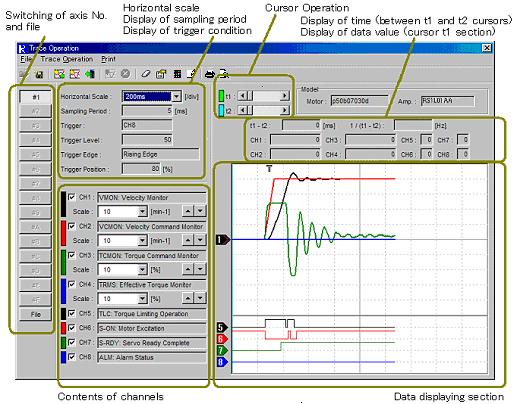
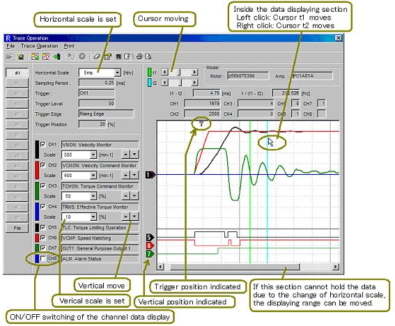
98 96
![Each function of trace operation can be accessed by selecting it in the menu bar of Trace Operation. [File] Open : Open the trace operation data stored in the file.](/docs-images/72/67199033/images/99-0.jpg "Possible to select it only at displaying trace operation data saved in a file. Save : Save the trace operation data which is now being displayed.")
 In Trace mode Right) In Scroll mode [Trace Operation] Trace Start + Trace Data Read : Directs the trace start (data sampling start) to servo amplifier.")
99 Each function of trace operation can be accessed by selecting it in the menu bar of Trace Operation. [File] Open : Open the trace operation data stored in the file. Possible to select it only at displaying trace operation data saved in a file. Save : Save the trace operation data which is now being displayed. Save As: Save the trace operation data which is now being displayed as the other name in a file. Exit: Exit trace operation. Left) In Trace mode Right) In Scroll mode [Trace Operation] Trace Start + Trace Data Read : Directs the trace start (data sampling start) to servo amplifier. Monitors data sampling status of servo amplifier. When completing sampling, read the trace operation data from servo amplifier and indicate it. Possible to select it only at displaying trace operation data of servo amplifier. Possible to select only at Trace Mode for trace mode select in trace operation setting of servo amplifier. Trace Start : Directs the trace start (data sampling start) to servo amplifier. Possible to select it only at displaying trace operation data of servo amplifier. Possible to select only at Trace Mode for trace mode select in trace operation setting of servo amplifier. 97
100 Trace Data Read : Monitors data sampling status of servo amplifier. When completing sampling, read the trace operation data from servo amplifier and indicate it. If data sampling keeps, continues to monitor it. Possible to select it only at displaying trace operation data of servo amplifier. Possible to select only at Trace Mode for trace mode select in trace operation setting of servo amplifier. Monitor Start : Reads data continuously from the servo amplifier and starts displaying scroll mode data. Possible to select it only at displaying trace operation data of servo amplifier. Possible to select only at Scroll Mode for trace mode select in trace operation setting of servo amplifier. Monitor Stop : Stops displaying scroll mode data (Stops updating the display). Possible to select it only at displaying trace operation data of servo amplifier. Possible to select only at Scroll Mode for trace mode select in trace operation setting inside the servo amplifier. Clear Trace Data : Deletes the trace operation data in servo amplifier. Deletes the trace operation data which is being displayed. Possible to select it only at displaying trace operation data of servo amplifier. Trace Operation Setting : Sets the trace operation for servo amplifier. Possible to select it only at displaying trace operation data of servo amplifier. Display Setting : Sets the trace operation and the color at printing. General Parameter Setting : Can set general parameters. For procedures, refer to 3.6. General Parameter Setting Possible to select it only at displaying trace operation data of servo amplifier. Measurement : The maximum, the minimum, the average, and the effect value of the waveform data under the display can be requested. Refer to Measurement of Trace Operation Possible to select it only while displaying the waveform data of the servo amplifier or the file that has been preserved. Note) Some servo amplifiers do not apply to the trace operation function depending on the type and the version. In those not applying, the following screen appears when selecting Trace Start + Trace Data Read, Trace Start, Monitor Start, and Trace Operation Setting. 98
![[Print] Print :Print the trace operation data which is being displayed. Impossible to select it when the trace operation data is not displayed.](/docs-images/72/67199033/images/101-1.jpg "Print Preview : Indicates the print image of trace operation data which is now being displayed. Impossible to select it when the trace operation data is not displayed. 3.26.1.")
101 [Print] Print :Print the trace operation data which is being displayed. Impossible to select it when the trace operation data is not displayed. Print Preview : Indicates the print image of trace operation data which is now being displayed. Impossible to select it when the trace operation data is not displayed Trace Operation Setting When click Trace Operation and Trace Operation Setting (E), the following appears. Here sets the contents of trace operation. When click OK after entering the contents, update them and start the trace. Click Cancel in case the setting is not updated. When executing trace setting for the servo amplifiers that do not apply to the trace operation function, the following screen appears. Trace operation function cannot be used. 99
102 Access the setting condition. Click Open and select the stored trace operation data file. Read the stored trace operation data. Select the trace mode. Select the trace operation mode among the following. Scroll mode 2 channel analog data and 2 channel digital data can be monitored by scroll mode. Possible to obtain 1000 data per channel at the minimum sampling period of 50ms. (Minimum sampling period may be different depending on the servo amplifier type.) Trace mode : Analog 4CH+Digital 4CH Trace the analog and digital data of 4 channel. 256 data per channel can be obtained. Trace mode : Analog 2CH+Digital 2CH Trace the analog and digital data of 2 channel. 512 data per channel can be obtained. Trace mode : Analog 1CH+Digital 1CH Trace the analog and digital data of 1 channel data per channel can be obtained. Analog setting Selects the data contents of CH1 to CH4. Selects the trigger signal. Analog data is classified under two kinds according to its data length. 2Byte type(in normal font) 4Byte type(in thick font) 4Byte type consumes the memory for 2 channels. Therefore, there are some channels that cannot be set. (In case of setting prohibited, setting contents will be displayed in pale color.) When select the 4Byte type data in CH1 to CH3, the next channel can not be used. (E.g. When selects 4Byte type in CH2, CH3 can not be used.) Cannot set to the largest numbered channel of each mode. 100
103 Setting to CH4 prohibited at Trace Mode : Analog 4CH + Digital 4CH. Setting to CH2 prohibited at Trace Mode : Analog 2CH + Digital 2CH. Setting to CH2 prohibited at Scroll Mode. 4Byte type data cannot be designated at Trace Mode : Analog 1CH + Digital 1CH. Digital setting Select the data contents of CH5 to CH8. Selects the trigger signal. Sampling setting Sets the sampling period. Product of the base time and the set value (multiple) becomes the sampling period. The duration enabling trace is displayed according to trace mode selection contents and sampling period setting. Trigger condition setting Set the trigger condition. Trigger level : In case the trigger signal is digital data, the setting is not required. Trigger edge Trigger position Select Contents of Trace Operation Setting The table below is the explanation of select contents for standard servo amplifier. Select contents may be different from the ones below depending on the amplifier type. Trace mode select Trace mode Note 3 Scroll Mode 2 (CH1, CH2) Trace Mode: 4 Analog 4CH (CH1, CH2, + Digital 4CH CH3, CH4) Trace Mode: Analog 2CH + Digital 2CH Trace Mode: Analog 1CH + Digital 1CH Number of monitor channels Analog data Digital data 2 (CH1, CH2) 1 (CH1) 2 (CH5, CH6) 4 (CH5, CH6, CH7, CH8) 2 (CH5, CH6) 1 (CH5) Data points at file save (per channel) Trigger setting Sampling period setting Notes Note 4 50ms or more Note points Not possible 256points Possible 0.25ms or more 512points Possible 0.25ms or more 1024points Possible 0.25ms or more Note 2 Note 2 Note 2 Note 1. Data is periodically read from the servo amplifier and waveform is updated. When sampling period is set to blow 200ms, the following environment (CPU operation frequency) is recommended. Data sampling period setting = 50ms or above, below 100ms.: CPU operation frequency 800MHz or above. Data sampling period setting = 100ms or above, below 200ms.: CPU operation frequency 350MHz or above. Data sampling period setting = 200ms or above. : CPU operation frequency 133MHz or above. 101
104 Even if recommended environment is met, display sometimes becomes abnormal. This abnormality may be resolved by reducing the load of PC, such as by terminating other applications or stopping some resident program. Note 2. Data is temporarily saved in the servo amplifier. After trigger generation or sampling stop, data is read and waveform is displayed. Note 3. The number of monitor channels of analog data is that for monitoring 2Byte type signals. Monitoring 4Byte type signals consumes twice as much the memory for 2Byte type signals (for 2 channels), therefore, the number of monitor channels becomes less. (For details, see the previous page.) Note 4. The range of sampling period setting may be different depending on the servo amplifier type. Analog CH select contents Select contents Note 2 Data type (Data length) Data range Note 3 Unit Note 4 Notes VMON:Velocity Monitor 2Byte ~ min-1 [mm/s] VCMON:Velocity Command Monitor 2Byte ~ min-1 [mm/s] TMON:Torque Monitor 2Byte ~ % [TMON:Force Monitor] TCMON:Torque Command Monitor 2Byte ~ % [TCMON:Force Command Monitor] PMON: Position Deviation Monitor 4Byte ~ Pulse APMON : Actual Position Monitor (Motor 4Byte Pulse Encoder) ~ CPMON:Command Position Monitor 4Byte Pulse ~ FMON : Position Command Pulse Monitor 2Byte Pulse (Position Command Pulse Input Frequency) ~ Sine U 2Byte ~ Note 5 PS-H:Absolute Encoder PS (High) 4Byte 0 ~ x2^32 P PS-L:Absolute Encoder PS (Low) 4Byte 0 ~ Pulse RegR:Regenerative Resistor Operation Ratio 2Byte 0 ~ % OPRT:Motor Operating Rate Monitor 2Byte 0 ~ % JRAT_MON : Control Loop Parameter_Load 2Byte 0 ~ % Inertia Moment Ratio Monitor [JRAT_MON : Control Loop Parameter_Load Mass Ratio Monitor] TLMON_EST:Load Torque (Estimated Value) 2Byte ~ % [TLMON_EST:Load Force (Estimated Value)] PMON_S:Position Deviation Monitor (2Byte) 2Byte ~ Pulse Note 6 Note 1. The select contents above show when the standard type servo amplifier is combined with R-Setup. For details of each signal, refer to Explanation of Parameter in the Servo Amplifier Instruction Manual. Note 2. Words in parentheses are for linear system. Note 3. Data range in this table shows the range where waveform display is possible. If servo amplifier deals with smaller range than the above, display is only within the range that servo amplifier can deal with. Note 4. Unit equivalent to 1LSB. Units in parentheses are for linear system. Note 5. Outputs Sin U (U phase electric angle). When U phase electric angle = 0 deg., monitor data = 0. When U phase electric angle = 90 deg., monitor data = (Peak at positive direction of sine waveform) When U phase electric angle = 270 deg., monitor data = (Peak at negative direction of sine waveform) Note 6. When position deviation becomes or below, data always show When position deviation becomes or above, data always show
105 Digital CH select contents Select contents Note 1 CONT1:General Purpose Input1 CONT2:General Purpose Input2 CONT3:General Purpose Input3 CONT4:General Purpose Input4 CONT5:General Purpose Input5 CONT6:General Purpose Input6 CONT7:General Purpose Input7 CONT8:General Purpose Input8 OUT1:General Purpose Output1 OUT2:General Purpose Output2 OUT3:General Purpose Output3 OUT4:General Purpose Output4 OUT5:General Purpose Output5 OUT6:General Purpose Output6 OUT7:General Purpose Output7 OUT8:General Purpose Output8 INP:In-Positioning NEAR:In-Position Near VCMP:Speed Matching TLC:Torque (Force) Limiting Operation VLC:Velocity Limiting Operation S-ON: Motor Excitation S-RDY:Servo Ready Complete CMD-ACK:Command Can be Accepted PCON-ACK : During Velocity Loop Proportional Control EGR-ACK:During Electric Gear Switching WNG-OFW:Following Warning WNG-OLW:Over Load Warning ALM:Alarm State Explanation of signal Indicates input signal state of general purpose input (CONT1~8) terminal. High Input photo coupler ON (CONT1~6) During negative logic signal input(cont7,8) Low Input photo coupler OFF (CONT1~6) During positive logic signal input (CONT7,8) Indicates the state of general purpose output (OUT1~8) terminal. High Output transistor OFF Low Output transistor ON High during positioning complete state. High during near range state. High during velocity conformity state. High during torque (force) limit operation. High during velocity limit operation. High during motor excitation. High during operation ready complete. High during command receive permit state. High during velocity loop proportional integration control state. High during electric gear switching state. High during excessive deviation warning. High during over load warning. High during alarm state. Note1. The select contents above show when the standard type servo amplifier is combined with R-Setup. Notes Note 2 Note2. Logic is reverse to the monitor display (monitor display page 04 of R-Setup). Q-SETUP State of output transistor Trace Operation digital data OUT*:General Purpose Output* Monitor Display page 04 OUT8-1: General Purpose Output OUT8~1Monitor Output transistor OFF High 0 Output transistor ON Low 1 103

106 Trace Operation Display Setting When click Trace Operation - Display Setting, the following appears. Here sets the data display of trace operation. When click OK after entering the contents, update them and start the trace. Click Cancel in case the setting is not updated. Analog CH1 to Digital CH8 Select the color, width, and mark in data display. t1, t2 Select the color and width in cursor display. Print by gray scale. When check this, display all colors in the tone of black/white at printing. 104
107 How to Use Trace Mode of Trace Operation Function This section explains how to use trace mode of trace operation function. 1. Set the trace operation. Open the trace operation setting by selecting Trace Operation - Trace Operation Setting (E) in the menu bar of trace operation. Select Trade Mode : at Trace Mode Select. Set others as necessary. After inputting, click OK to update the setting. 2. Start the trace. (In case of using Trace Start and Trace Data Read ) When select Trace Operation - Trace Start in the menu bar of trace operation, start the trace. Although servo amplifier starts sampling, the display of setup software remains unchanged. Once servo amplifier starts sampling, it continues until trigger is generated or the control power is shut off. (Sampling continues even after terminating the setup software or cutting off the cable.) After trigger generation, the data can be read by using Trace Data Read.) 3. Read the data and display it. (In case of using Trace Start and Trace Data Read ) When select Trace Operation - Trace Data Read in the menu bar of trace operation, read the trace data. In case of sampling in progress (waiting trigger), the following appears. Servo amplifier is sampling the data while waiting the trigger. When click Sampling Stop, stops sampling. (This detects the trigger falsely.) When click Cancel, this dialog box is closed. Even if click Cancel, servo amplifier continues sampling. 105
108 When the trigger is detected, switch to the dialog box after trigger is generating. When sampling in progress (after trigger generating), the following appears. Servo amplifier is sampling the data. The remaining time displays that of sampling. When the remaining time is 0 [sec], switch to Now Reading. When sampling is completed, the following appears. Reading the sampling data from servo amplifier. When the reading is completed normally, Now Reading disappears and trace operation data is displayed. 4. Execute Trace Start and Trace Data Read continuously. (When use Trace Start+Trace Data Read ) When select Trace Operation - Trace Start+Trace Data Read in the menu bar of trace operation, start the trace. When the trace starts, the following appears. Servo amplifier is sampling the data while waiting trigger generation. When click Sampling Stop, stops sampling. (This detects the trigger falsely.) 106
109 When click Cancel, this dialog box is closed. Even if click Cancel, servo amplifier continues sampling. Once servo amplifier starts sampling, it continues until trigger is generated or the control power is shut off. (Sampling continues even after terminating the setup software or cutting off the cable.) After trigger generation, the data can be read by using Trace Data Read.) When the trigger is detected, the following dialog box appears. Servo amplifier is sampling the data. The remaining time displays the period until the sampling completes. When the remaining time is 0[sec], the following dialog box appears. Reading the sampling data from servo amplifier. When the reading is completed normally, Now Reading disappears and trace operation data is displayed. 5. Trace operation data display in progress When trace operation data read is complete and the data is displayed on the screen, following operations are possible. Saving trace operation data. Cursor Operation. Expanding horizontal range. Changing vertical axis range for each channel. ON/OFF of the vertical and data. 107
110 How to Use Scroll Mode of Trace Operation Function This section explains how to use scroll mode of trace operation function. 1. Set the trace operation setting. Open the trace operation setting by selecting Trace Operation - Trace Operation Setting (E) in the menu bar of trace operation. Select Scroll Mode at Trace Mode Select. Set others as necessary. After inputting these, click OK to update the setting. 2. Select Trace Operation Monitor Start in the menu bar of trace operation to start the monitor. Read the data for each sampling period from the servo amplifier and update the data displaying screen. Monitoring operation (data read, updating data displaying screen) continues until monitoring stops or any stop occurs due to communication error. During monitoring operation, following operations are possible. Changing vertical axis range for each channel. ON/OFF of the vertical and data. Depending on the sampling period setting, data display on the screen may be broken. This phenomena occurs when communication or displaying transaction is not in time for the sampling period setting. Reduce the load of PC by terminating other applications or stop resident program. If not improved by these measures, change the sampling period setting. When broken display (data missing) occurs very frequently, monitoring may stop. Note that display is broken when menu bar is opened during monitor operation. 3. Select Trace Operation Monitor Stop to stop monitoring. During monitor stop, following operations are possible. Saving trace operation data. Cursor operation. Changing vertical axis range for each channel. ON/OFF of the vertical and data. 108

111 Measurement of Trace Operation When click Trace Operation - Measurement, the following appears. Here sets the data display of trace operation. The maximum, the minimum, the average, and the effective value of the waveform data under the display can be requested. Measurement Range Select the measurement data. All Data : All the data under the display is measured. Between t1 and t2 : The data between the cursor t1 and the cursor t2 is measured. Measurement Star The measurement of waveform data begins, and the measurement result is updated. Outputs to File The measurement result is outputted to a text file. Print Preview Indicates the print image of measurement result. Max: The maximum value in measurement data is displayed. Min: The minimum value in measurement data is displayed. Ave: The average value of the measurement data is displayed. RMS: The effective value (root mean square value) of the measurement data is displayed. 109
112 Note for "Measurement" of "Trace Operation" - Note for data loss at "Scroll Mode". In case of data loss resulted form communication environment or setting of sampling frequency etc. There is a possibility that no data exists. In the trace operation measurement function, the area where no data exists will be excluded from measurement target. The measurement function can be used even when data is lost. * When all the data is lost in the measurement range (no data exists), the measurement result is "0". - Initial data of "Scroll Mode" At "Scroll Mode", 1000 point data is always displayed. When monitoring starts, this 1000 point data is cleared to "0". Therefore, from monitoring start until the time 1000 times as long as the sampling frequency will have past, initial data "0" exists which is not actual data. The Measurement function of Trace Operation treats this initial data "0" as measurement target. - Initial data of "Trace Mode" At "Trace Mode", data buffer is cleared to "0" when tracing starts. Therefore, when a trigger is detected and sampling stops before Tracing Time will have past after tracing start, initial data "0" exists which is not actual data. The Measurement function of Trace Operation treats this initial data "0" as measurement target. * Specify by cursor the measurement range and make the actual data as measurement target. 110
113 3.27. System Analysis In the system analysis, system can be easily analyzed by operating servo amplifier and servomotor for the duration from hundreds ms to tens seconds. This function operates the servomotor, therefore, take care for safety. Click Trial Operation and Adjustment System Analysis in the menu bar of main screen, and the following system analysis screen appears. System analysis data is displayed and saved here. System analysis setting Displays measurement conditions when analysis data now on display is obtained. Control loop parameter monitor Displays contents of control loop parameter when analysis data now on display is obtained. Range Indicates vertical axis range for Gain and Phase. Gain can change vertical axis and the vertical. Auto and Default can automatically adjust the vertical axis range and the vertical. Auto : Adjusts the vertical axis range and the vertical to appropriate setting. Default : Returns the vertical axis range and the vertical to initial setting. 111
 There is numerical display for t1 cursor position data (frequency, gain and phase) at the right of t1 scroll bar. t2 Indicates the color of t2 cursor and the horizontal.")
114 t 1 Indicates the color of t1 cursor and the horizontal. When data is displayed, t1 cursor can be moved by scroll bar. (Left click on the data moves the t1 cursor to the position.) There is numerical display for t1 cursor position data (frequency, gain and phase) at the right of t1 scroll bar. t2 Indicates the color of t2 cursor and the horizontal. When data is displayed, t2 cursor can be moved by scroll bar. (Right click on the data moves the t2 cursor to the position.) There is numerical display for t2 cursor position data (frequency, gain and phase) at the right of t2 scroll bar. Generation ratio of torque (thrust) limit state while measuring Indicates the generation ratio of torque (thrust) limit state when obtaining analysis data. If this ratio is high, there is a possibility that result of analysis may be different from actual system. Each function of the system analysis can be accessed by selecting one in the menu bar of system analysis. [File] Open : Opens and displays system analysis data file. Close : Clears the data while system analysis data file is displayed. Possible to select only when system analysis data file is displayed. Save As : Saves the displayed data in the file. Possible to select only when analysis result data or system analysis data file is displayed. Exit : Exits the system analysis. 112
![[System Analysis] Start Data Measurement & Analysis : Starts data measurement and analysis. Possible to select only at online.](/docs-images/72/67199033/images/115-0.jpg "In the reduction installed R-Setup, selection is possible, however, data measurement/analysis cannot be performed. General Parameter Setting : Can set general parameters. For procedures, refer to 3.6.")
115 [System Analysis] Start Data Measurement & Analysis : Starts data measurement and analysis. Possible to select only at online. In the reduction installed R-Setup, selection is possible, however, data measurement/analysis cannot be performed. General Parameter Setting : Can set general parameters. For procedures, refer to 3.6. General Parameter Setting Possible to select only at online. Data Clear : Clears the data on the screen while displaying analysis result. Possible to select only when analysis result is displayed. Display Setting : Sets the system analysis screen and the color for printing. [Print] Print : Prints the displayed system analysis data. Do not select this unless system analysis data is displayed on the screen. Print Preview (V) : Displays the image of the displayed system analysis data. Do not select this unless system analysis data is displayed on the screen [Help] Cautions : Opens a file describing cautions on using the system analysis. This file is html type, which can be opened where Internet Explorer 4.0 or above is installed. 113
116 Data Measurement & Analysis Start Click System Analysis Data Measurement & Analysis Start, and the following screen appears. The motor operates in positive/negative move to measure the data for analysis. After data measurement, analysis can start. See the following procedure for Data Measurement & Analysis Start. 1. Select the axis number for which data measurement & analysis is to be executed in Servo Amplifier Select. 2. Click [Execute], and the following screen appears. Click [OK], and the following screen appears if the servo amplifier does not apply to the system analysis function. In this servo amplifier, system analysis function cannot be used. When the servo amplifier is not in ready complete state, the following screen appears. 114

117 It is not ready for data measurement for system analysis. Ready not complete state occurs when servo amplifier is in alarm state, when the main circuit power is not supplied, or when Trial Operation and Adjustment is being executed by digital operator. When data measurement becomes ready, click [Execute] again. When servo amplifier is in ready complete state, the following screen appears. 3. Set options at the end of data measurement and system analysis. If Trial Operation End Alarm is to be generated when data measurement ends (when analysis starts), click Trial Operation End Alarm at End, and if not, click No Trial Operation End Alarm at End. In system analysis setting, torque (thrust) command at data measurement and frequency range to be analyzed are selected. 4. Confirm the control loop parameter that its value is as targeted. (If not, exit Data Measurement & Analysis Start once and change the value by general parameter setting.) 115
118 5. Click [Servo ON], and the following screen appears during alarm generation. If servo amplifier cannot become Servo ON, the following appears. After making it possible, click [Servo ON] again. At Servo ON state, [Execute] button can be used. 116
![6. Click [Execute], and the followings are displayed and data measurement is executed.](/docs-images/72/67199033/images/119-0.jpg "Depending on the selected measurement frequency range, data measurement time varies.")


119 6. Click [Execute], and the followings are displayed and data measurement is executed. Depending on the selected measurement frequency range, data measurement time varies. Therefore, display of Data measurement in progress sometimes lasts long. Click [Stop], and the measurement stops with Servo ON state remaining. Click [Servo OFF], and the measurement stops with Servo OFF. When data measurement cannot be executed properly due to overtravel generation, the following appears. After removing the cause, execute data measurement again. 7. When data measurement ends normally, the following appears. Click [OK], and the following appears and analysis starts with Servo OFF. Click [Cancel], and the measured data is canceled to return to the state before data measurement is executed (Servo ON state). 117

120 8. When analysis ends normally, the following result is displayed General Parameter Setting Select System Analysis General Parameter Setting, and the general parameter setting screen appears. Here, general parameter can be set without closing system analysis screen. For the procedure, refer to Transmit Parameter [File -> Amplifier]. 118

121 Display Setting Click System Analysis Display Setting, and the following screen appears. Trace operation data display is set here. Click [OK] after inputting every setting, and the contents are updated and data is displayed again. If the setting is not to be updated, click [Cancel]. Gain, Phase Color of data display, line width and mark are selected. t1, t2 Color and line width for cursor display are selected. Print in gray scale At the time of checking and printing, all the colors are displayed in black/white tone. 119

122 3.28. Status History Monitor This function can monitor the status history recorded in the servo amplifier. It is used only when combined with the servo amplifier with positioning function. Select Monitor Status History from the menu bar on the main screen, and the following screen appears. The status history is displayed according to the following procedure. 1 Select the axis number of the servo amplifier whose status history is to be displayed from Servo Amplifier Selection. 2 Click [Execute]. When the target amplifier is not corresponding to the status history monitoring function or ready is not yet complete, the following screen appears. If the target amplifier is the one with positioning function and corresponding to the status history monitoring function, wait for a few seconds and click [Execute] again. Also the state of ready not complete occurs when Test Operation and Adjustment is being executed form the digital operator. When the servo amplifier is in the ready complete status, the following screen appears. 120


123 Axis Display of the axis number of the amplifier whose status history is being displayed. Model Display of the model numbers of the motor and amplifier. Status History Display of the status history. The data is read from the amplifier every few seconds and the contents are automatically updated. * If the amplifier status changes while the data is being read from the amplifier, wrong contents may be displayed. (Check the counter alignment to confirm that the contents are right.) Functions of status history display can be accessed from the menu bar in the status history display screen. [File] Save As.: Save the displayed status history in a text file. 121

124 * I The saved text file cannot be opened in the R-SETUP set-up software. Use other application corresponding to text file (*.txt) to open it. Exit : Exit status history display screen. [Amplifier] Status History Clear : Clear the status history information recorded in the servo amplifier Status History Clear Click Amplifier Status History Clear in the status history display screen, and the following screen appears. Status history is erased here. Click [OK], and the status history information is erased and the following screen appears. Click [OK] to go back to the status history display screen. If the display contents have been automatically updated, the erased status history will be displayed. 122

125 3.29. Point Data Setting Select Point Data (S) Point Data Setting.., and the point data setting screen will appear. Specify the target to be edited and operated in this screen. File edit mode Refer to File Edit Mode for details. Select File Edit and click [Execute]. Point data file can be created and edited. EXT. mode Refer to EXT Mode. Select 1 axis from #1 to #F, specify EXT. in OPERATE selection and click [Execute]. The point data of the servo amplifier on line can be edited. This is possible even while operated from the upper device. * This can be used when combined with the amplifier with positioning function. * This can be selected only while on line. R-SETUP mode (Servo amplifier selection + R-SETUP selection) Refer to R-SETUP Mode, Test Run (R-SETUP Mode) and Point Move (R-SETUP Mode). Select 1 axis from #1 to #F, specify R-SETUP in OPERATE selection and click [Execute]. The point data editing and point function test run of the servo amplifier on line can be executed. This is not possible while operated from the host unit. * This can be used when combined with the amplifier with positioning function. * This can be selected only while on line. 123
126 File Edit Mode Select Point Data (S) Point Data Setting from the menu bar of main screen, and the point data setting screen appears. Select File Edit, click [Execute], and the following screen appears. Point data file can be created and edited. Setting File: File edit mode Model Number The servo amplifier model number and combined motor when file was saved. * Display is only for the file in which the point data read form the servo amplifier is saved, not for a new file created by File Edit. OPERATE, Amplifier status No display in File Edit Mode. Point data The set value can be directly input at the cursor marked in yellow. ( Point Number cannot be edited.) Edited point data will be displayed in red. Once saved in the file, the point data will be black again. * If file is not open, point data cannot be edited. 124
![Point number search Input the point number to be searched and click [Search]. The cursor will move to the specified point number. Copy Point data can be copied to that of other point number.](/docs-images/72/67199033/images/127-0.jpg "* Refer to 3.28.8 Copy (R-SETUP / EXT. / File Edit Mode) for details. Functions of point data setting (File edit mode) can be accessed from the menu bar of the point data setting screen.")
![[File] New File : Create a new point data file. * Refer to 3.28.9 New file (File Edit Mode) for details. Open.: Open the point data file. Save.: Save the point data being edited in the file. Save As.](/docs-images/72/67199033/images/127-1.jpg ".: Save the point data being edited into a file with another name. Exit : Exit the point data setting screen. [Amplifier] Cannot be selected in File Edit Mode. [Print] Print Preview.")
127 Point number search Input the point number to be searched and click [Search]. The cursor will move to the specified point number. Copy Point data can be copied to that of other point number. * Refer to Copy (R-SETUP / EXT. / File Edit Mode) for details. Functions of point data setting (File edit mode) can be accessed from the menu bar of the point data setting screen. [File] New File : Create a new point data file. * Refer to New file (File Edit Mode) for details. Open.: Open the point data file. Save.: Save the point data being edited in the file. Save As..: Save the point data being edited into a file with another name. Exit : Exit the point data setting screen. [Amplifier] Cannot be selected in File Edit Mode. [Print] Print Preview.: Displays the point data print image. Print.: Print the point data. Text output.: Point data is output as a text file (*.txt). 125
![* The saved text file cannot be opened in the R-SETUP setup software. Use other applications corresponding to text file (*.txt) to open it. [Help] Descriptions for point data setting. 3.29.2. Ext.](/docs-images/72/67199033/images/128-0.jpg "Mode Select Point Data (S) Point Data Setting from the menu bar of the main screen, and point data setting screen appears. Select 1 axis from #1 to #F, specify EXT.")
128 * The saved text file cannot be opened in the R-SETUP setup software. Use other applications corresponding to text file (*.txt) to open it. [Help] Descriptions for point data setting Ext. Mode Select Point Data (S) Point Data Setting from the menu bar of the main screen, and point data setting screen appears. Select 1 axis from #1 to #F, specify EXT. in OPERATE selection, and click [Execute], and then the following screen appears. Point data in the servo amplifier can be edited. This is possible even while operated from the host unit. 126
129 If the target servo amplifier is not applicable to point data setting function, or in the state of ready not complete, the following screen appears. If the target amplifier is the one with positioning function and applicable to point data setting function, wait for a few seconds and click [Execute] again. Also the state of ready not complete occurs when Test Run and Adjustment is being executed form the digital operator. Axis The servo amplifier axis number whose point data is being edited. OPERATE EXT. : EXT. mode. Model number Servo amplifier model number and combined motor. Amplifier status Amplifier status and actual position. Point data The set value can be directly input at the cursor marked in yellow. ( Point Number cannot be edited.) Edited point data will be displayed in red. Once read in the servo amplifier, the display will be black again. * Point data cannot be edited unless executing [Amplifier] [Read All Point Data from Amplifier]. Point number search Input the point number to be searched and click [Search]. The cursor will move to the specified point number. Copy Point data can be copied to that of other point number. * Refer to Copy (R-SETUP / EXT. / File Edit Mode) for details. Teaching This can be set to the data of the point number which specifies actual position. * Refer to Teaching (R-SETUP / EXT. Mode) for details. 127

130 Write The point data with the cursor in is written into the servo amplifier. Only one point data can be written. * When not executing [Amplifier] [Read All Point Data from Amplifier], all the point data being edited are in Original status. If Write is executed in this status, 0 is written in the target point data. * When the servo amplifier is in busy status (while the point data of the target is being executed), writing is not possible. Functions of point data setting (EXT. Mode) can be accessed from the menu bar on the point data setting screen. [File] Save As : Point data being edited is saved in a file. Exit : Exit the point data setting screen. * [New.], [Open ] and [Save.] cannot be used in the EXT. mode. [Amplifier] Read All Point Data from Amplifier : Read the point data from the servo amplifier as a batch. Write All Point Data to Amplifier : Write the point data being edited to the servo amplifier as a batch. * [Write All Point Data to Amplifier] cannot be used unless executing [Amplifier] [Read All Point Data from Amplifier] * When the servo amplifier is in busy status (while point data of the target is being executed), writing is not possible. * [Alarm Reset ] cannot be used in the EXT. mode. 128
131 [Print] Print Preview : Display of point data print image. Print : Print the point data. Text Output : Point data is output as text file (*.txt) * The saved text file cannot be opened in the R-SETUP setup software. Use other applications corresponding to text file (*.txt) to open it. [Help] Descriptions are displayed about setting contents of point data R-Setup Mode Select [Point Data (S)] [Point Data Setting ] from the menu bar on the main screen, and point data setting screen appears. Select 1 axis from #1 to #F, specify R-SETUP in OPERATE selection, and click [Execute], and then the following screen appears. Point data in the servo amplifier can be edited and test run for pointing functions can be executed. This is not possible while operated from the host unit. 129
132 If the target servo amplifier is not applicable to point data setting function, or in the state of ready not complete, the following screen appears. If the target amplifier is the one with positioning function and applicable to point data setting function, wait for a few seconds and click [Execute] again. Also the state of ready not complete occurs when Test Run and Adjustment is being executed form the digital operator. Axis Servo amplifier axis number whose point data is being edited. OPERATE R-SETUP : R-SETUP mode. Model number Servo amplifier model number and combined motor. Amplifier status Servo Amplifier status and actual position. 130
133 Point data The set value can be directly input at the cursor. Edited point data will be displayed in red. Once the point data is written in the servo amplifier, the display will be black again. * Point data cannot be edited unless executing [Amplifier] [Read All Point Data from Amplifier]. Point number search Input the point number to be searched and click [Search]. The cursor will move to the specified point number. Copy Point data can be copied to that of other point number. * Refer to Copy (R-SETUP / EXT. / File Edit Mode) for details. Teaching This can be set to the data of the point number which specifies the actual position. * Refer to Teaching (R-SETUP / EXT. Mode) for details. Write The point data with the cursor in is written into the servo amplifier. Only one point data can be written. * When not executing [Amplifier] [Read All Point Data from Amplifier], all the point data being edited are in Original status. If Write is executed in this status, 0 is written in the target point data. * When the servo amplifier is in busy status (while the point data of the target is being executed), writing is not possible. Tab [Test Run] Click Tab [Test Run], and the test run screen appears. Test Run can be executed. Tab [Point Move] Click Tab [Point Move], and the point move screen appears. Point move can be executed. Refer to Point Move (R-SETUP mode) for details. Functions of point data setting (R-SETUP Mode) can be accessed from the menu bar on the point data setting screen. 131
![[File] Save As : Point data being edited is saved in a file. Exit : Exit the point data setting screen. * [New.], [Open ] and [Save.] cannot be used in the R-SETUP mode.](/docs-images/72/67199033/images/134-0.jpg "[Amplifier] Read All Point Data from Amplifier : Read the point data from the servo amplifier as a batch.")
134 [File] Save As : Point data being edited is saved in a file. Exit : Exit the point data setting screen. * [New.], [Open ] and [Save.] cannot be used in the R-SETUP mode. [Amplifier] Read All Point Data from Amplifier : Read the point data from the servo amplifier as a batch. Write All Point Data to Amplifier : Write the point data being edited to the servo amplifier as a batch. * [Write All Point Data to Amplifier] cannot be used unless executing [Amplifier] [Read All Point Data from Amplifier] * When the servo amplifier is in busy status (while point data of the target is being executed), writing is not possible. Alarm Reset : Order the amplifier to reset the alarm. Refer to Alarm Reset for details. [Print] Print Preview : Display of point data print image. Print : Print the point data. Text Output : Point data is output as text file (*.txt) * The saved text file cannot be opened in the R-SETUP setup software. Use other applications corresponding to text file (*.txt) to open it. 132
![[Help] Descriptions are displayed about setting contents of point data. 3.29.4. Test Run (R-Setup Mode) Click the tab [Test Run], and the following screen appears.](/docs-images/72/67199033/images/135-0.jpg "Servo amplifier JOG operation, 1 Step move and homing operation can be executed here. * Take precautions for safety, since the motor operates in Test Run.")
135 [Help] Descriptions are displayed about setting contents of point data Test Run (R-Setup Mode) Click the tab [Test Run], and the following screen appears. Servo amplifier JOG operation, 1 Step move and homing operation can be executed here. * Take precautions for safety, since the motor operates in Test Run. If an alarm is issued during Test Run, motor excitation turns OFF. Fully prepare the control device or others prior to Test Run. * Depending on the amplifier status or setting, the motor cannot stop even if functions of Stop, Cancel or Resume are clicked on. Preparation is necessary prior to operation in order that emergency stop can quickly be implemented by shutting off the power of amplifier main circuit. 133
![1) Parameter setting Clicking [Edit] enables an input to each parameter (during parameter editing). Clicking [Edit cancel] aborts the value and returns to initial status.](/docs-images/72/67199033/images/136-0.jpg "Clicking [Write] writes the input value into the servo amplifier and returns to initial status. * During test run, parameter setting cannot be changed.")
![* During parameter editing, test run cannot start, or switching the tab into [Point Data] or [Point Move] is impossible.](/docs-images/72/67199033/images/136-1.jpg "* High speed 1 step move, Low speed 1 step move, High speed jogging speed and Low speed jogging speed are the same parameters as the ones included in the general parameters with the same names.")
136 1) Parameter setting Clicking [Edit] enables an input to each parameter (during parameter editing). Clicking [Edit cancel] aborts the value and returns to initial status. Clicking [Write] writes the input value into the servo amplifier and returns to initial status. * During test run, parameter setting cannot be changed. * During parameter editing, test run cannot start, or switching the tab into [Point Data] or [Point Move] is impossible. * High speed 1 step move, Low speed 1 step move, High speed jogging speed and Low speed jogging speed are the same parameters as the ones included in the general parameters with the same names. Change of settings here is reflected in the general parameter. Initial status [Edit] [Edit Cancel] [Write] During parameter editing 2) Parameter display Contents of setting for override value and homing type are displayed 3) Handshaking MSTR : The status of amplifier output signal MSTR is displayed. [MFIN] : The same function as amplifier input signal MFIN. However, the status of external signal MFIN cannot be monitored. 134
137 4) Motor excitation Clicking [Servo ON] starts the motor excitation. Clicking [Servo OFF] cuts the motor excitation. * When the servo amplifier is in the status of not ready (motor cannot excite), this automatically changes to [Servo OFF]. 5) Jog current limit If jogging operation is executed while current limit is being selected by clicking [current limit], the output current is limited by pre-set limit value. Clicking [current limit] again releases the limit. 6) Jog operation execution [High speed + ] : Starts forward jogging operation at high jogging speed. [Low speed + ] : Starts forward jogging operation at low jogging speed. [Low speed - ] : Starts backward jogging operation at low jogging speed. [High speed - ] : Starts backward jogging operation at high jogging speed. Clicking [Cancel] cancels the jogging operation. * During servo off, jogging operation cannot be executed. * During parameter editing or execution of other test run, jogging operation cannot start. * During jogging operation execution, parameter editing or other test run cannot be used. Switching the tab into [Point data] or [Point move], or selecting a menu is impossible. * When servo turns OFF due to alarms or others during jogging operation execution, the jogging operation stops into the servo OFF status. During Servo ON Jogging operation is being stopped. Jogging operation is being executed. L_jog+ ( H_jog+, L_jog-, H_jog- ) Cancel 135
138 7) 1 Step move [High speed + ] : Starts forward 1 step move at high jogging speed. [Low speed + ] : Starts forward 1 step move at low jogging speed. [Low speed - ] : Starts backward 1 step move at low jogging speed. [High speed - ] : Starts backward 1 step move at high jogging speed. Clicking [Cancel] cancels the 1 step move. Clicking [Resume] suspends the 1 step move. Clicking [Continue] releases the suspension and resumes the move. When the specified move is complete, it returns to stop status. * During servo OFF1 step move cannot be executed., * During parameter editing and other test run, 1 step move cannot start. * While 1 step move is being executed or during suspension, parameter editing and other test run cannot be used. Switching the tab into [Point data] or [Point move], or selecting a menu is impossible. * When servo turns OFF due to alarms or others during execution, the operation stops into the servo OFF status. During Servo ON While stopping While execution L_stp+ ( H_stp+, L_stp-, H_stp- ) Cancel 1-Step movement Completed While suspension Resume Continue Cancel 1-Step movement Completed 136
139 8) Homing Clicking [Start] starts the homing operation. Clicking [Cancel] stops the homing operation. Clicking [Resume] suspends the homing operation. Clicking [Continue] releases the suspension and resumes the homing operation. While clicking [Override], the move speed changes by the specified override ratio. * During servo OFF, homing cannot be executed. * During parameter editing and other test run, homing cannot start. * While homing is being executed or during suspension, parameter editing and other test run cannot be used. Switching the tab into [Point data] or [Point move], or selecting a menu is impossible. * When servo turns OFF due to alarms or others during execution, the operation stops into the servo OFF status. During servo ON While stopping While homing Start Cancel Homing Completed While suspension Resume Continue Cancel Homing Completed 137
![3.29.5. Move Point (R-Setup Mode) Click the tab [Move Point] while R-SETUP mode is being executed, and the following screen appears. Servo amplifier point and home position setting are executed here.](/docs-images/72/67199033/images/140-0.jpg "* Take precautions for safety, since the motor operates in Move Point operation. If an alarm is issued during operation, motor excitation turns OFF.")
140 Move Point (R-Setup Mode) Click the tab [Move Point] while R-SETUP mode is being executed, and the following screen appears. Servo amplifier point and home position setting are executed here. * Take precautions for safety, since the motor operates in Move Point operation. If an alarm is issued during operation, motor excitation turns OFF. Fully prepare the control device or others prior to execution. * Depending on the amplifier status or setting, the motor cannot stop even if functions of Stop, Cancel or Resume are clicked on. Preparation is necessary prior to operation in order that emergency stop can quickly be implemented by shutting off the power of amplifier main circuit. 1) Setting Clicking [Edit] enables an input of set value to each item (during set value editing). Clicking [Edit Cancel] aborts the input value and returns to initial status. Clicking [Write] writes the input value into the servo amplifier and returns to initial status. * During point execution, the set value cannot be changed. 138
![* While the set value is being edited, point execution cannot start. Switching the tab into [Point Data] or [Test Run] is impossible.](/docs-images/72/67199033/images/141-0.jpg "Initial status Editing set value Edit Edit Cancel Write 2) Parameter display Operation contents during test run : Parameters are displayed.")
 Motor excitation Clicking [Servo ON] starts the motor excitation.")
141 * While the set value is being edited, point execution cannot start. Switching the tab into [Point Data] or [Test Run] is impossible. Initial status Editing set value Edit Edit Cancel Write 2) Parameter display Operation contents during test run : Parameters are displayed. 3) History monitor The latest information of status history recorded in the servo amplifier (Last1) is displayed. 4) Handshaking MSTR : The status of amplifier output signal MSTR is displayed. [MFIN] : The same function as amplifier input signal MFIN. However, the status of external signal MFIN cannot be monitored. 5) Motor excitation Clicking [Servo ON] starts the motor excitation. Clicking [Servo OFF] cuts the motor excitation. * When the servo amplifier is in the status of not ready (motor cannot excite), this automatically changes to [Servo OFF]. 6) Point execution Clicking [Start] starts the point execution. Clicking [Cancel] cancels the point execution. Clicking [Resume] suspends the point execution. Clicking [Continue] releases the suspension and resumes the point execution. 139
![While clicking [Override], the move speed changes by the specified override ratio. * During servo OFF, point execution is impossible. * During set value editing, point execution cannot start.](/docs-images/72/67199033/images/142-0.jpg "* While pointing is being executed, editing the set value or other test run cannot be used. Switching the tab into [Point data] or [Test Run], or selecting a menu is impossible.")
 Home position setting Clicking [Start]")
142 While clicking [Override], the move speed changes by the specified override ratio. * During servo OFF, point execution is impossible. * During set value editing, point execution cannot start. * While pointing is being executed, editing the set value or other test run cannot be used. Switching the tab into [Point data] or [Test Run], or selecting a menu is impossible. * When servo turns OFF due to alarms or others during point execution, it stops into the servo OFF status. During servo ON While stopping During execution Start Cancel Move Point Completed During suspension Resume Continue Cancel Move Point Completed 7) Home position setting Clicking [Start] executes the home position setting. * Home position setting can only be selected during servo ON. 140


143 Alarm Reset (R-Setup Mode) Select Amplifier Alarm Reset. from the menu bar of the point data setting screen, and alarm reset can be executed. Click Yes, and alarm reset is executed. * The display above also appears when there are alarms that cannot be reset. However, the alarm status remains in the servo amplifier side Teaching (R-Setup / EXT. Mode) Click [Teaching] in the tab [Point Data] or [Test Run], the following screen appears. Actual position can be set at point data. 141

144 1) Point number When actual position is to be set at only 1 point data, select Actual Position is set as one point data and specify the point number of the destination. When actual position is to be set at multiple point data, select Actual position is set as two or more point data, and specify the point numbers of the destination. Point numbers in consecutive areas can be specified. (There must be the smallest point number in the left and the biggest in the right.) 2) Amplifier status Servo amplifier status and actual position are displayed. This actual position is set. (If the motor is not stopped completely, there may be a slight difference between the motor actual position, display of actual position and the value set by teaching. 3) Execution Click [Execute], and actual position is set. The only data to be set is the position in the point data Copy (R-Setup / EXT. / File Edit Mode) Click [Copy] in the tab [Point Data], the following screen appears. Point data can be copied to other point data. 142

145 1) Copy destination When the set value of copy source is to be set at only one point data, select Copy to one point data, and specify the point number of copy destination. When the set value of copy source is to be set at two or more point data, select Copy to two or more data, and specify the point numbers of the destination. Point numbers in consecutive areas can be specified. (There must be the smallest point number in the left and the biggest in the right.) 2) Copy source Specify the point number of the point data to be copied from. 3) Execution Click [Execute], and the point data is copied. All the set values including speed, position and move mode are copied New (File Edit Mode) Select File New. From the menu bar of the point data setting screen, and a new point data file can be created in OFF line status. Select Unit: Select the unit from Unit Pulse and Unit mm. D_dpo (Number of decimal places of position and speed): Set the number of decimal places of the position and the speed set at point data. Click [OK], and the following screen appears. Input a new file name and click [Save], and point data of the new file can be edited. 143
146 * Only a file name is specified here. A new file will be formally created by executing [Save] or [Save As] on the point data setting screen. 144
![3.30. Transmit Point Data [Amplifier -> File] At Transmit Point Data [Amplifier -> File], all the point data of the amplifier are read and saved in a file as a batch.](/docs-images/72/67199033/images/147-1.jpg "Select Point Data (S) Transmit Point Data [Amplifier -> File] (F), and the screen of transmit point data [Amplifier -> File] appears.")
147 3.30. Transmit Point Data [Amplifier -> File] At Transmit Point Data [Amplifier -> File], all the point data of the amplifier are read and saved in a file as a batch. Select Point Data (S) Transmit Point Data [Amplifier -> File] (F), and the screen of transmit point data [Amplifier -> File] appears. See the following procedure of data transmission from the servo amplifier to the point data file. 1. Select the axis number of the transmission source servo amplifier from Transmission source. 2. Click [Browse] in Transmission destination, and the following file saving dialog appears. Specify the place to save in and file name, then click [Save]. 3. Click [Execute], and the following screen appears. The point data is read from the servo amplifier. 145
148 4. When point data reading from the amplifier is complete normally, the display of Now Reading disappears and the following screen appears. The read point data of the servo amplifier is saved in the file. If the target amplifier does not correspond to the point data setting function, or in the status of ready not complete, the following screen appears. If the target amplifier is the one with positioning function and applicable to point data setting function, wait for a few seconds and click [Execute] again. Also the state of ready not complete occurs when Test Run and Adjustment is being executed from the digital operator. 146
![3.31. Transmit Point Data [File -> Amplifier] At Transmit Point Data [File -> Amplifier], the point data saved in the file are directly written in the servo amplifier as a batch.](/docs-images/72/67199033/images/149-0.jpg "Select Point Data (S) Transmit Point Data [File -> Amplifier] (A), and the following screen appears. See the following procedure of point data transmission from file to servo amplifier. 1.")
![Select the axis number of the transmission destination servo amplifier from Transmission destination. 2. Click [Browse] in Transmission source, and the following file selecting dialog appears.](/docs-images/72/67199033/images/149-1.jpg "Specify the place to save in and file name, then click [Save]. Select the file whose point data is to be read in the servo amplifier, and click [Open]. 3.")
149 3.31. Transmit Point Data [File -> Amplifier] At Transmit Point Data [File -> Amplifier], the point data saved in the file are directly written in the servo amplifier as a batch. Select Point Data (S) Transmit Point Data [File -> Amplifier] (A), and the following screen appears. See the following procedure of point data transmission from file to servo amplifier. 1. Select the axis number of the transmission destination servo amplifier from Transmission destination. 2. Click [Browse] in Transmission source, and the following file selecting dialog appears. Specify the place to save in and file name, then click [Save]. Select the file whose point data is to be read in the servo amplifier, and click [Open]. 3. Click [Execute], and point data batch writing starts. 147

150 If the specified file is not a point data file, the following screen appears. In this case, point data transmission cannot be executed. If the settings of file and the servo amplifier are different, the following screens appear. In these cases, point data transmission cannot be executed. * Modify the servo amplifier settings (for unit, speed, decimal places for position) to make them the same as the file settings, and then transmit again. 148
Happy Link Software INSTRUCTION MANUAL
 Happy Link Software INSTRUCTION MANUAL 101001E-3 HAPPY Contents Regarding this software Normal Operation -------------------------------------------------------------------------------------------------
Copyright 2014 YASKAWA ELECTRIC CORPORATION All rights reserved. No part of this publication may be reproduced, stored in a retrieval system, or
 Copyright 2014 YASKAWA ELECTRIC CORPORATION All rights reserved. No part of this publication may be reproduced, stored in a retrieval system, or transmitted, in any form, or by any means, mechanical, electronic,
Scanner Utility for Microsoft Windows Version 9.6. User's Guide
 P3PC-E892-03EN Scanner Utility for Microsoft Windows Version 9.6 User's Guide For Use with Microsoft Windows 98, Windows Me, Windows 2000 and Windows XP Introduction Thank you for purchasing the "Scanner
FUJITSU TWAIN 32 Scanner Driver. Scanner Utility for Microsoft Windows Version User's Guide
 P3PC- E417-02EN FUJITSU TWAIN 32 Scanner Driver Scanner Utility for Microsoft Windows Version 9.10 User's Guide For Use with Microsoft Windows 98, Windows Me, Windows 2000 and Windows XP Introduction
DOCUMENT SCANNER INSTRUCTIONS. Space. Backup. Count Only. New File. Scanner. Feeding Option Manual Auto Semi-Auto
 E FILM F Scanner A Space Count Only New File Feeding Option Manual Auto Semi-Auto Backup DOCUMENT SCANNER INSTRUCTIONS NOTICE q Copyright 2001 by CANON ELECTRONICS INC. All rights reserved. No part of
LCC-100 software User manual
 User Manual Pressure Temperature Humidity Air Velocity Airflow Sound level New LCC-100 software User manual Configuration software for Monostats - Class 50 and 100 units - ranges - relays - set points
OPERATION MANUAL MIMAKI ENGINEERING CO., LTD.
 OPERATION MANUAL MIMAKI ENGINEERING CO., LTD. http://www.mimaki.co.jp/ E-mail:traiding@mimaki.co.jp D200674 About FineCut for CorelDRAW Thank you very much for purchasing a product of Mimaki. FineCut,
TOSHIBA MACHINE CO., LTD.
 User s Manual Product SHAN5 Version 1.12 (V Series Servo Amplifier PC Tool) Model SFV02 July2005 TOSHIBA MACHINE CO., LTD. Introduction This document describes the operation and installation methods of
FX 3U -20SSC-H Quick Start
 FX 3U -20SSC-H Quick Start A Basic Guide for Beginning Positioning Applications with the FX 3U -20SSC-H and FX Configurator-FP Software Mitsubishi Electric Corporation January 1 st, 2008 1 FX 3U -20SSC-H
User manuel. Hybrid stepper servo drive
 User manuel Hybrid stepper servo drive 1 Overview Hybridstepper servo drive system integrated servo control technology into the digital step driver. It adopts typical tricyclic control method which include
PSF-520 Instruction Manual
 Communication software for HA-520/HA-680 Series PSF-520 Instruction Manual Thank you for implementing our AC servo driver HA-520, HA-680 series. The PSF-520 software sets various parameters and checks
DMMDRV Software User Manual. Version: A10 50 / December 2015 Manual Code: DSFEN A
 DMMDRV Software User Manual Version: A10 50 / December 2015 Manual Code: DSFEN A1050 1215 Contents Section 1. General Software Safety Precautions 1.1 DYN2 System Safety 1.2 DYN4 System Safety 1.3 Servo
Using CME 2 with AccelNet
 Using CME 2 with AccelNet Software Installation Quick Copy (with Amplifier file) Quick Setup (with motor data) Offline Virtual Amplifier (with no amplifier connected) Screen Guide Page 1 Table of Contents
INSTRUCTION MANUAL IP REMOTE CONTROL SOFTWARE RS-BA1
 INSTRUCTION MANUAL IP REMOTE CONTROL SOFTWARE RS-BA FOREWORD Thank you for purchasing the RS-BA. The RS-BA is designed to remotely control an Icom radio through a network. This instruction manual contains
General-Purpose AC Servo. MELSERVO-JE Servo amplifier INSTRUCTION MANUAL (TROUBLE SHOOTING)
") General-Purpose AC Servo MELSERVO-JE Servo amplifier INSTRUCTION MANUAL (TROUBLE SHOOTING) D Safety Instructions Please read the instructions carefully before using the equipment. To use the equipment
General-Purpose AC Servo MELSERVO-JE Servo amplifier INSTRUCTION MANUAL (TROUBLE SHOOTING) D Safety Instructions Please read the instructions carefully before using the equipment. To use the equipment
Tech Note #3: Setting up a Servo Axis For Closed Loop Position Control Application note by Tim McIntosh September 10, 2001
 Tech Note #3: Setting up a Servo Axis For Closed Loop Position Control Application note by Tim McIntosh September 10, 2001 Abstract: In this Tech Note a procedure for setting up a servo axis for closed
General-Purpose AC Servo. MELSERVO-JE Servo amplifier INSTRUCTION MANUAL (TROUBLE SHOOTING)
") General-Purpose AC Servo MELSERVO-JE Servo amplifier INSTRUCTION MANUAL (TROUBLE SHOOTING) F Safety Instructions Please read the instructions carefully before using the equipment. To use the equipment
General-Purpose AC Servo MELSERVO-JE Servo amplifier INSTRUCTION MANUAL (TROUBLE SHOOTING) F Safety Instructions Please read the instructions carefully before using the equipment. To use the equipment
IB Nov User s Manual. KFM Series Application Software. FCTester. Ver. 1.1
 IB011511 Nov. 2006 User s Manual KFM Series Application Software FCTester Ver. 1.1 Use of This Manual Please read through and understand this User s Manual before operating the product. After reading,
DMMDRV 2017 Software User Manual. Version: A1324 / December 2017 Manual Code: DSFEN A
 DMMDRV 2017 Software User Manual Version: A1324 / December 2017 Manual Code: DSFEN A1324 1217 Contents Section 1. General Software Safety Precautions 1.1 DYN2 System Safety 1.2 DYN4 System Safety 1.3 Servo
MR210AU / MR220AU User s Manual
 1/2-Axes Motor Control Unit MR210AU / MR220AU User s Manual 2004-02-18 Ver. 1.0 2007-04-04 Ver. 1.1 2008-12-12 Ver. 3.3 2010-06-30 Ver. 3.4 NOVA electronics Introduction Thank you for purchasing MR210AU/MR220AU
BLuAC5 Brushless Universal Servo Amplifier
 BLuAC5 Brushless Universal Servo Amplifier Description The BLu Series servo drives provide compact, reliable solutions for a wide range of motion applications in a variety of industries. BLu Series drives
Printer Software Guide
 Printer Software Guide (For Canon Compact Photo Printer Solution Disk Version 6) Windows 1 Contents Safety Precautions...3 Read This First...4 About the Manuals...4 Printing Flow Diagram...5 Printing...6
Instruction Manual for the Software of ASSAN V2 Series Receiver
 Instruction Manual for the Software of ASSAN V2 Series Receiver I. Setup 1. Double click SETUP to enter the welcome interface and click Next. 2. Enter your name and company name and click Next. 3. Select
General-Purpose AC Servo. MELSERVO-JE Servo amplifier INSTRUCTION MANUAL (TROUBLE SHOOTING)
") General-Purpose AC Servo MELSERVO-JE Servo amplifier INSTRUCTION MANUAL (TROUBLE SHOOTING) B Safety Instructions Please read the instructions carefully before using the equipment. To use the equipment
General-Purpose AC Servo MELSERVO-JE Servo amplifier INSTRUCTION MANUAL (TROUBLE SHOOTING) B Safety Instructions Please read the instructions carefully before using the equipment. To use the equipment
BLuAC5 Brushless Universal Servo Amplifier
 BLuAC5 Brushless Universal Servo Amplifier Description The BLu Series servo drives provide compact, reliable solutions for a wide range of motion applications in a variety of industries. BLu Series drives
CME 2 User Guide P/N CC Revision A June 2009
 CME 2 User Guide P/N CC95-00454-000 Revision A June 2009 CME 2 User Guide TABLE OF CONTENTS About This Manual... 5 1: Introduction... 7 1.1: Host Computer Requirements... 8 1.2: Amplifier Commissioning
Quick Start Guide. Setup and Scanning. Try the Additional Features. English
 English Quick Start Guide Be sure to install the software programs before connecting the scanner to the computer! Setup and Scanning Check the Package Contents p.3 Install the Software Windows Macintosh
PC Tune PC Tune Test Procedures for 5100 Series Portable Radios
 PC Tune PC Tune Test Procedures for 5100 Series Portable Radios Part Number 002-9998-6513014 August 2008 Copyright 2006, 2007, 2008 by EFJohnson Technologies The EFJohnson Technologies logo, PC Configure,
MTY (81)
") This manual describes the option "d" of the SMT-BD1 amplifier: Master/slave electronic gearing. The general information about the digital amplifier commissioning are described in the standard SMT-BD1 manual.
This manual describes the option "d" of the SMT-BD1 amplifier: Master/slave electronic gearing. The general information about the digital amplifier commissioning are described in the standard SMT-BD1 manual.
Combo Scanner. User Manual
 Combo Scanner User Manual I. Unpack the Combo Scanner Backlight Holder Combo Scanner Business card Fixture Photo/Business Card Holder User Manual Quick Installation Guide Note This Combo Scanner supports
Troubleshooting 12. This section explains the items to check when problems occur, and troubleshooting by the use of error displays or operation state.
 Troubleshooting 12 This section explains the items to check when problems occur, and troubleshooting by the use of error displays or operation state. 12-1 Actions for Problems..........................................
FUJITSU TWAIN 32 Scanner Driver
 P3PC-1242-02ENC2 FUJITSU TWAIN 32 Scanner Driver Scanner Utility for Microsoft Windows Version 9.17 User's Guide For Use with Microsoft Windows 98, Windows Me, Windows 2000 and Windows XP (* For Windows
Tarocco Closed Loop Motor Controller
 Contents Safety Information... 3 Overview... 4 Features... 4 SoC for Closed Loop Control... 4 Gate Driver... 5 MOSFETs in H Bridge Configuration... 5 Device Characteristics... 6 Installation... 7 Motor
ID Photo Processor. Batch photo processing. User Guide
 ID Photo Processor Batch photo processing User Guide 2015 Akond company 197342, Russia, St.-Petersburg, Serdobolskaya, 65a Phone/fax: +7(812)384-6430 Cell: +7(921)757-8319 e-mail: info@akond.net http://www.akond.net
Quick Start Guide. Setup and Scanning. Try the Additional Features. English
 English Quick Start Guide Be sure to install the software programs before connecting the scanner to the computer! Setup and Scanning Check the Package Contents p.3 Install the Software Windows Macintosh
JCM TRAINING OVERVIEW WBA-XX
 JCM TRAINING OVERVIEW WBA- Phone # (800) 683-7248 (702) 651 0000 Technical Support # (702) 651-3444 Fax # (702) 651-0214 E-mail techsupport@jcm-american.com Web Address http://www.jcm-american.com 1 2
1) Press the Connect button to establish communication with NS300 or NS500.
 Press the Connect button to establish communication with NS300 or NS500.") ENGINEERING PUBLICATION MOTION CONTROL DIVISION PRODUCT:NSXXX CATEGORY: TECH NOTE ENGINEER: Chris Knudsen SUBJECT: NSXXX EXAMPLE CONFIGURATION DISTRIBUTION: MCD NSxxx Configuration Guide NSxxx software
ENGINEERING PUBLICATION MOTION CONTROL DIVISION PRODUCT:NSXXX CATEGORY: TECH NOTE ENGINEER: Chris Knudsen SUBJECT: NSXXX EXAMPLE CONFIGURATION DISTRIBUTION: MCD NSxxx Configuration Guide NSxxx software
Quick Immunity Sequencer
 Part No. Z1-003-152, IB006433 Nov. 2006 USERʼS MANUAL PCR-LA Series Application Software SD003-PCR-LA Quick Immunity Sequencer Ver. 1.0 Use of This Manual Please read through and understand this User s
The ideal K-12 science microscope solution. User Guide. for use with the Nova5000
 The ideal K-12 science microscope solution User Guide for use with the Nova5000 NovaScope User Guide Information in this document is subject to change without notice. 2009 Fourier Systems Ltd. All rights
Network ScanGear. User s Guide ENG
 Network ScanGear User s Guide Please read this guide before operating this equipment. After you finish reading this guide, store it in a safe place for future reference. ENG Organization of this User s
Automatic Tool Changer (ATC) for the prolight A Supplement to the prolight 1000 User s Guide
 for the prolight A Supplement to the prolight 1000 User s Guide") Automatic Tool Changer (ATC) for the prolight 1000 A Supplement to the prolight 1000 User s Guide 1 1995 Light Machines Corporation All rights reserved. The information contained in this supplement (34-7221-0000)
Automatic Tool Changer (ATC) for the prolight 1000 A Supplement to the prolight 1000 User s Guide 1 1995 Light Machines Corporation All rights reserved. The information contained in this supplement (34-7221-0000)
TRWinProg 101by Chris Bowman October 10
 TRWinProg 101by Chris Bowman October 10 TRWinProg is a Windows based program for serial programming of encoders. The program allows viewing of setup data stored within the encoder and allowing the user
Flash Blaster II v.2.00 for the Falcon digital console Falcon ENGLISH
 User's manual for: Flash Blaster II v.2.00 for the Falcon digital console Falcon ENGLISH http://www.lemaudio.com Overview Installation Communication Menùs&Functions Problems Upgrades Flash Blaster II v.2.00
FUJITSU TWAIN 32 Scanner Driver
 P3PC-1472-09ENZ0 FUJITSU TWAIN 32 Scanner Driver Scanner Utility for Microsoft Windows Version 9.19 User's Guide For Use with Microsoft Windows 2000, Windows XP, Windows Server 2003, Windows Server 2008
VBRC 5. Radio Communicator. Installer Manual
 VBRC 5 Radio Communicator Installer Manual 10 / 10 / 2013 CONTENT 1. INTRODUCTION...3 2. SYSTEM STRUCTURE...3 3. SYSTEM PROGRAMMING WITH PC SOFTWARE...5 4. TROUBLESHOOTING...6 5. FIRMWARE UPGRADE...7 6.
OVEN INDUSTRIES, INC. Model 5C7-362
 OVEN INDUSTRIES, INC. OPERATING MANUAL Model 5C7-362 THERMOELECTRIC MODULE TEMPERATURE CONTROLLER TABLE OF CONTENTS Features... 1 Description... 2 Block Diagram... 3 RS232 Communications Connections...
PROSOFT User Manual 3.03 VERSION
 Via monte Nero, 40/B 21049 TRADATE (VA) ITALY hone: +39 (0)331841070 Fax:+39 (0)331841950 - e-mail:datexel@datexel.it - www.datexel.it ROSOFT User Manual 3.03 VERSION GENERAL DESCRITION ROSOFT is a software
Maxsine AC SERVO. EP100 QuickGuide. Maxsine Electric Co.,Ltd
 Maxsine EP100 QuickGuide AC SERVO Maxsine Electric Co.,Ltd 1.1 Standard wiring Position control Maxsine EP100(B) SERVO DRIVER SERVOMOTOR 3 Phase AC220V NFB MC PE R S T r CN2 U V W PE 14 5V 2 3 4 1 4 Pins
BANTAM INSTRUMENTS SOFTWARE USER S MANUAL MIL-STD-461E PRE-COMPLIANCE MEASUREMENT SYSTEM MODEL EMC-461. Model EMC-461 Software User s Manual
 BANTAM INSTRUMENTS MIL-STD-461E PRE-COMPLIANCE MEASUREMENT SYSTEM MODEL EMC-461 SOFTWARE USER S MANUAL MIL-STD-461E PRE-COMPLIANCE MEASUREMENT SYSTEM MODEL EMC-461 Software User s Manual BANTAM INSTRUMENTS
DEFINITION OF WARNING, CAUTION, AND NOTE
 α B 6515E/3 DEFINITION OF WARNING, CAUTION, AND NOTE DEFINITION OF WARNING, CAUTION, AND NOTE This manual includes safety precautions for protecting the user and preventing damage to the machine. Precautions
Studuino Icon Programming Environment Guide
 Studuino Icon Programming Environment Guide Ver 0.9.6 4/17/2014 This manual introduces the Studuino Software environment. As the Studuino programming environment develops, these instructions may be edited
Blue Bamboo P25 Device Manager Guide
 Blue Bamboo P25 Device Manager Guide Version of Device Manager: 1.1.28 Document version: 2.3 Document date: 2011-09-20 Products: P25 / P25-M / P25i / P25i-M BLUE BAMBOO Headquarters Blue Bamboo Transaction
Printer Software Guide
 Printer Software Guide (For Canon CP Printer Solution Disk Version 4) Macintosh 1 Contents Safety Precautions...3 Read This First...4 About the Manuals...4 Printing Flow Diagram...5 Printing...7 Starting
Vinyl Cutter Instruction Manual
 Vinyl Cutter Instruction Manual 1 Product Inventory Inventory Here is a list of items you will receive with your vinyl cutter: Product components (Fig.1-4): 1x Cutter head unit complete with motor, plastic
Quick Start Guide. Setup and Scanning. Try the Additional Features. English
 English Quick Start Guide Be sure to install the software programs before connecting the scanner to the computer! Setup and Scanning Check the Package Contents p.3 Install the Software Windows Macintosh
Analog / Pulse Input Type
 M0008424E TYPE S Analog / Pulse Input Type For Rotary Motor Details of the change history The third edition (C) Page ⅱ Safety precautions when using Safe Torque Off function is added. Page 1-1 Explanation
RPS-9000 Programming Software for the TYT TH-9000
 for the TYT TH-9000 Memory Types Memories Limit Memories VFO Channels Receive Frequency Transmit Frequency Offset Frequency Offset Direction Channel Spacing Name Tone Mode CTCSS Rx CTCSS DCS Rx DCS Memory
The Discussion of this exercise covers the following points: Differential-pressure transmitter. Differential-pressure transmitter
 Exercise 2-1 Two-Wire Transmitter EXERCISE OBJECTIVE Become familiar with HART point-to-point connection of a two-wire transmitter. DISCUSSION OUTLINE The Discussion of this exercise covers the following
WEB I/O. Wireless On/Off Control USER MANUAL
 Wireless On/Off Control Technical Support: Email: support@encomwireless.com Toll Free: 1 800 617 3487 Worldwide: (403) 230 1122 Fax: (403) 276 9575 Web: www.encomwireless.com Warnings and Precautions Warnings
INSTRUCTIONS. Scanning Utility 5000 INSTRUCTIONS DOCUMENT SCANNER ENGLISH
 DOCUMENT SCANNER INSTRUCTIONS Scanning Utility 5000 INSTRUCTIONS ENGLISH Be sure to thoroughly read this Instructions before using this unit, and store this manual in a safe place after use. FCC REGULATIONS
USER GUIDE. Piezo Motor with Encoder. Installation & Software Control Guide. (For Piezo Motor Model LPM-2M, LPM-5, PM-1124R)
") www.dtimotors.com USER GUIDE Piezo Motor with Encoder Installation & Software Control Guide (For Piezo Motor Model LPM-2M, LPM-5, PM-1124R) Version 05312018v11 Page 0 Table of Contents 1.0 Introduction...
www.dtimotors.com USER GUIDE Piezo Motor with Encoder Installation & Software Control Guide (For Piezo Motor Model LPM-2M, LPM-5, PM-1124R) Version 05312018v11 Page 0 Table of Contents 1.0 Introduction...
AN-SERV-009. Luis Miranda 1
 THIS INFORMATION PROVIDED BY AUTOMATIONDIRECT.COM TECHNICAL SUPPORT IS SUPPLIED "AS IS", WITHOUT ANY GUARANTEE OF ANY KIND. These documents are provided by our technical support department to assist others.
5008 Dual Synthesizer Configuration Manager User s Guide (admin Version) Version valontechnology.com
 Version valontechnology.com") 5008 Dual Synthesizer Configuration Manager User s Guide (admin Version) Version 1.6.1 valontechnology.com 5008 Dual Synthesizer Module Configuration Manager Program Version 1.6.1 Page 2 Table of Contents
5008 Dual Synthesizer Configuration Manager User s Guide (admin Version) Version 1.6.1 valontechnology.com 5008 Dual Synthesizer Module Configuration Manager Program Version 1.6.1 Page 2 Table of Contents
Exercise 2-2. Four-Wire Transmitter (Optional) EXERCISE OBJECTIVE DISCUSSION OUTLINE. Ultrasonic level transmitter DISCUSSION
 EXERCISE OBJECTIVE DISCUSSION OUTLINE. Ultrasonic level transmitter DISCUSSION") Exercise 2-2 Four-Wire Transmitter (Optional) EXERCISE OBJECTIVE Become familiar with HART point-to-point connection of a four-wire transmitter. DISCUSSION OUTLINE The Discussion of this exercise covers
Exercise 2-2 Four-Wire Transmitter (Optional) EXERCISE OBJECTIVE Become familiar with HART point-to-point connection of a four-wire transmitter. DISCUSSION OUTLINE The Discussion of this exercise covers
Contents. Nikon Scan for Windows. Scanner Control Software and TWAIN Source. Reference Manual. Overview Before You Begin.
 Contents Overview Before You Begin System Requirements Software Installation Basic Operations Scanner Control Software and TWAIN Source Nikon Scan for Windows Reference Manual The Scan Window Opening the
General-Purpose AC Servo. MELSERVO-J4 Servo amplifier INSTRUCTION MANUAL (TROUBLE SHOOTING)
") General-Purpose AC Servo MELSERVO-J4 Servo amplifier INSTRUCTION MANUAL (TROUBLE SHOOTING) K Safety Instructions Please read the instructions carefully before using the equipment. To use the equipment
General-Purpose AC Servo MELSERVO-J4 Servo amplifier INSTRUCTION MANUAL (TROUBLE SHOOTING) K Safety Instructions Please read the instructions carefully before using the equipment. To use the equipment
AZ Series. Function Edition. Closed Loop Stepping Motor and Driver Package. Operation. I/O signals. Parameter
 HM-6262 Closed Loop Stepping Motor and Driver Package Operation I/O signals Parameter AZ Series Function Edition Method of control via Modbus RTU (RS-485 communication) Method of control via industrial
Getting Started with TrangoLink
 Getting Started with TrangoLink Overview: TrangoLink allows you to configure and monitor your EAGLE PLUS, FALCON, or PTZ-900 transmitters and receivers. On the EAGLE PLUS and FALCON transmitters, you can
Drive CM User Manual
 The Best Choice for the Most Benefit! At LS Mecapion, we are committed to providing premium benefits to all of our customers. Drive CM User Manual Servo Configuration Tool Ver. 1.0 Safety Precautions -
Quick Start Guide for the PULSE PROFILING APPLICATION
 Quick Start Guide for the PULSE PROFILING APPLICATION MODEL LB480A Revision: Preliminary 02/05/09 1 1. Introduction This document provides information to install and quickly start using your PowerSensor+.
General-Purpose AC Servo. Servo Amplifier Instruction Manual (Troubleshooting)
") General-Purpose AC Servo Servo Amplifier Instruction Manual (Troubleshooting) SAFETY PRECAUTIONS (Please read the instructions carefully before using the equipment.) To use the equipment correctly, do
General-Purpose AC Servo Servo Amplifier Instruction Manual (Troubleshooting) SAFETY PRECAUTIONS (Please read the instructions carefully before using the equipment.) To use the equipment correctly, do
Analog / Pulse Input Type
 M0008424F TYPE S Analog / Pulse Input Type For Rotary Motor Details of the change history The sixth edition (F) Safety precautions - i Corrected: the time from power supply shutdown to when operator starts
Nikon View DX for Macintosh
 Contents Browser Software for Nikon D1 Digital Cameras Nikon View DX for Macintosh Reference Manual Overview Setting up the Camera as a Drive Mounting the Camera Camera Drive Settings Unmounting the Camera
Endurance R/C Wi-Fi Servo Controller 2 Instructions
 Endurance R/C Wi-Fi Servo Controller 2 Instructions The Endurance R/C Wi-Fi Servo Controller 2 allows you to control up to eight hobby servos, R/C relays, light controllers and more, across the internet
CME 2 User Guide P/N Revision 00 January 2014
 CME 2 User Guide P/N 16-01157 Revision 00 January 2014 CME 2 User Guide Contents About This Manual... 6 Related Documentation... 6 Copyrights... 6 Document Validity... 6 Revision History... 8 1: Introduction...
ADMS-847 Programming Software for the Yaesu FT-847
 for the Yaesu FT-847 Memory Types Memories Limit Memories VFO A VFO B Home Satellite Memories One Touch Memory Channel Functions Transmit Frequency Offset Frequency Offset Direction CTCSS DCS Skip The
EasyMotion User s Manual Ver
 EasyMotion User s Manual Ver. 3.01 2001 Applied Cybernetics Chapter 1. Introduction. Welcome to EasyM otion. This complete motion system setup program provides you with all the tools you need to test hardware
TIGER HOOK 2004 AMCOE INC.
 TIGER HOOK 2004 AMCOE INC. PIN PARTS SIDE SOLDER SIDE PIN 1 VIDEO RED VIDEO GREEN 1 2 VIDEO BLUE VIDEO SYNC 2 3 SPEAKER + SPEAKER - 3 4 EXTRA - 4 5 EXTRA - STOP 2 EXTRA - ALL STOP 5 6 EXTRA - STOP 3 6
CSMIO/IP-A motion controller and Mach4
 CSMIO/IP-A motion controller and Mach4 Quick start guide Axis tuning 1) We start the configuration with Motor axis assignment. As you can see in the picture above - the Motor0 was assign to X axis (the
Digital Microscope. User Manual
 Digital Microscope User Manual Features The digital microscope provides 10~200X adjustable magnification range. The build-in high-performance white LED can illuminate the object without using any auxiliary
Troubleshooting Alarm Displays Warning Displays
 10 10.1 Alarm Displays............................................10-2 10.1.1 List of Alarms...................................................... 10-2 10.1.2 of Alarms............................................
GNSS Conductor GF. User s Guide. (Document No. SE )
") GNSS Conductor GF User s Guide (Document No. ) www.furuno.com IMPORTANT NOTICE No part of this manual may be reproduced or transmitted in any form or by any means, electronic or mechanical, including photocopying
GNSS Conductor GF User s Guide (Document No. ) www.furuno.com IMPORTANT NOTICE No part of this manual may be reproduced or transmitted in any form or by any means, electronic or mechanical, including photocopying
IX Feb Operation Guide. Sequence Creation and Control Software SD011-PCR-LE. Wavy for PCR-LE. Ver. 5.5x
 IX000693 Feb. 015 Operation Guide Sequence Creation and Control Software SD011-PCR-LE Wavy for PCR-LE Ver. 5.5x About This Guide This PDF version of the operation guide is provided so that you can print
DXXX Series Servo Programming...9 Introduction...9 Connections HSB-9XXX Series Servo Programming...19 Introduction...19 Connections...
 DPC-11 Operation Manual Table of Contents Section 1 Introduction...2 Section 2 Installation...4 Software Installation...4 Driver Installastion...7 Section 3 Operation...9 D Series Servo Programming...9
M K TYPE S. Analog/Pulse Input Type. for Rotary Motor. Instruction Manual
 M0005349K TYPE S Analog/Pulse Input Type for Rotary Motor Instruction Manual Preface This product corresponds with the shipping regulations given in the Export Trade Control Ordinance (Table 1, item 16)
V-SFT Ver. 5/ Ver. 6 Update Procedure
 5073NE6 V-SFT Ver. 5/ Ver. 6 Update Procedure (for 8.1/ 10) This document explains how to update your V-SFT, after installing on 8.1/ 10 using CD-ROM Ver. 5.4.19.0 or earlier. Windows Vista/ 7 (32-bit)
MMS TESTER FG320 OPERATING INSTRUCTIONS. valid from 11/2017. Machine Monitoring Systems
 Machine Monitoring Systems MMS TESTER FG320 OPERATING INSTRUCTIONS valid from 11/2017 PROFESS, spol. s r.o., Květná 5, 326 00 Plzeň Tel: 377 454 411, 377 240 470 Fax: 377 240 472 E-mail: profess@profess.cz
PalmGauss SC PGSC-5G. Instruction Manual
 PalmGauss SC PGSC-5G Instruction Manual PalmGauss SC PGSC 5G Instruction Manual Thank you very much for purchasing our products. Please, read this instruction manual in order to use our product in safety
MSCLDC Closed Loop Dc Positioning System
 ELECTRIC LINEAR MOTION PRODUCTS MSCLDC Closed Loop Dc Positioning System User Manual TOL-O-MATIC, INC Excellence in Motion 3600-4054 Copyright 1997 Tol-O-Matic, Incorporated. All rights reserved. Axidyne
DIGITAL CAMERA. Quick Start Guide
 En DIGITAL CAMERA Quick Start Guide Table of Contents pg. 1 Check the package contents pp. 2 11 Take Pictures Step 1 Charge the batteries...pg. 2 Step 2 Attach the camera strap...pg. 3 Step 3 Insert the
Software Operational Manual
 Software Operational Manual for Easy Servo Drives ES-D508/808/1008 www.leadshine.com SM-ES-R20121030 ii Leadshine reserves the right to make changes without further notice to any products herein to improve
Development of the AC Servo Amplifier
 New Products Introduction Development of the AC Servo Amplifier SANMOTION R Series ADVANCED MODEL TypeS Yuuji Ide Michio Kitahara Yasutaka Narusawa Masahisa Koyama Naoaki Takizawa Kenichi Fujisawa Hidenao
Lab 2: Introduction to Real Time Workshop
 Lab 2: Introduction to Real Time Workshop 1 Introduction In this lab, you will be introduced to the experimental equipment. What you learn in this lab will be essential in each subsequent lab. Document
USB-MC USB Motion Controller
 USB-MC USB Motion Controller Con2 I/O port, to I/O card Con4 Aux port, inputs and outputs Con3 parallel port, to I/O card Con1 USB port to PC Con5 external power supply 8 24 VDC Status LED - + Comm. LED
FUJITSU TWAIN 32 Scanner Driver
 P3PC-1002-01ENC2 FUJITSU TWAIN 32 Scanner Driver Scanner Utility for Microsoft Windows Version 8.14 User's Guide For Microsoft Windows 95 and Windows NT (* For Windows 98, Windows Me, Windows 2000 and
Instruction Manual. Ultrasonic and Radar
 Instruction Manual ABM Gateway Software for 3 & 4 wire Ultrasonic and Radar Instruction Manual Revision 5.8 NOTE: Windows 7 and 8 users are asked to use default screen size (100%). To change from Larger
FRUIT BONUS 2 nd Generation 2004 AMCOE INC.
 PIN PARTS SIDE SOLDER SIDE PIN 1 VIDEO RED VIDEO GREEN 1 2 VIDEO BLUE VIDEO SYNC 2 3 SPEAKER + SPEAKER - 3 4 EXTRA - 4 5 EXTRA - STOP 2 EXTRA - ALL STOP 5 6 EXTRA - STOP 3 6 7 TICKET OUT BUTTON - panel
PROGRAMMER INSTRUCTION MANUAL Please read this manual before using the machine. Please keep this manual within easy reach for quick reference.
 PROGRAMMER INSTRUCTION MANUAL Please read this manual before using the machine. Please keep this manual within easy reach for quick reference. BAS-761 Thank you very much for purchasing the Brother Industrial
Servo Tuning Tutorial
 Servo Tuning Tutorial 1 Presentation Outline Introduction Servo system defined Why does a servo system need to be tuned Trajectory generator and velocity profiles The PID Filter Proportional gain Derivative