32-Bit-Digital Signal Controller TMS320F2812
|
|
|
- Bathsheba George
- 6 years ago
- Views:
Transcription
1 Module 15 : C28x Digital Motor Control 32-Bit-Digital ignal Controller TM320F2812 Texas Instruments Incorporated European Customer Training Centre Uniersity of Applied ciences Zwickau (FH) 15-1
2 Electrical Motor families Motor Classification: Direct Direct Current Motors (DC) Alternating Current Motors (AC) Asynchronous Induction Motor (ACI) Permanent Magnet ynchronous Motor (PMM) ynchronous Brushless DC Motor (BLDC) 15-2
3 Phase - Motor (PMM) For most three phase machines, the winding is stationery, and magnetic field is rotating Three phase machines hae three stator windings, separated 120 apart physically Three phase stator windings produce three magnetic fields, which are spaced 120 in time = = = π ω π ω ω t j c t j b t j s a e I i e I i e I i = = = Ω Ω Ω π π t jp c t jp b t jp a e E e e E e e E e N a c b i a i c i b
4 3 Phase - Motor 1,50 1,00 0,50 0, ,50-1,00-1,50 Three stationary pulsating magnetic fields C B` ia A` Fc Fb A Phase currents Fa B C ` ia ib ic ωt The three phase winding produces three magnetic fields, which are spaced 120 apart physically. When excited with three sine waes that are a 120 apart in phase, there are three pulsating magnetic fields. The resultant of the three magnetic fields is a rotating magnetic field. 15-4
5 ynchronous Motor C B` F N F A` A N B C` Rotor field φ tator field Rotor is carrying a constant magnetic field created either by permanent magnets or current fed coils The interaction between the rotating stator flux, and the rotor flux produces a torque which will cause the motor to rotate. The rotation of the rotor in this case will be at the same exact frequency as the applied excitation to the rotor. This is synchronous operation. ω 60. f Rotor speed (rad/s) : Ω = gies (r.pm) Example: a 2 poles pair p p f : AC supply frequency (Hz) p : motor poles pair per phase synchronous motor will run at 1500 r.pm for a 50Hz AC supply frequency 15-5
6 ynchronous Motors: BLDC and PMM Phase A Hall A C B ` F i a N A ` A F B C ` Back EMF of BLDC Motor Both (typically) hae permanent-magnet magnet rotor and a wound stator BLDC (Brushless DC) motor is a permanent-magnet magnet brushless motor with trapezoidal back EMF PMM (Permanent-magnet magnet synchronous motor) is a permanent-magnet magnet brushless motor with sinusoidal back EMF E a θ e 1,50 1,00 0,50 Back EMF of PMM ea eb ec Phase B Hall B Phase C i b i c θ e θ e 0, ,50-1,00-1,50 ωt Hall C 15-6
7 3 Phase Voltage Inerter ix PWM signals to control Power witches DC - Voltage + Upper & lower deices can not be turned on simultaneously (dead band) 3 - phase outputs to motor terminals Power witching Deices 15-7
8 calar Control cheme ( V/f ) ω + Σ PI V V/f profile f PWM Command PWM1 PWM2 PWM3 PWM4 PWM5 PWM6 3- Phase Inerter peed scaling peed calculator + imple to implement: All you need is three sine waes feeding the motor + Position information not required (optional). Doesn t delier good dynamic performance. Torque deliery not optimized for all speeds 15-8
9 Field Oriented Control (FOC) Field Oriented Control (FOC) or Vector Control, is a control strategy for 3-phases 3 induction motors where the torque producing and magnetizing components of the stator flux are separately controlled. The approach consists in imitating the DC motors operation FOC will be possible with system information: currents, oltages, flux and speed. 15-9
10 FOC control scheme Inerse Park ω + ω Σ I PID Q + I D + Field Weakening Controller Σ Σ PID PID V Q V D D,Q d,q q r V q V d pace Vector PWM PWM1 PWM2 PWM3 PWM4 PWM5 PWM6 3- Phase Inerter r I Q D,Q I q d,q i a i b I D d,q I d a,b,c i c Park T Clarke T peed Calculator q r : i a + i b + i c = 0 ome key mathematical components are required! 15-10
11 PARK transform (1929): PARK transform (1929): (Vs): oltage ector applied to motor stator (index s) = ) ( s s V Park transform is a referential change [ ] [ ] = = = ) ( and. ) ( 1 ) 3 4 sin( ) 3 4 cos( 1 ) 3 2 sin( ) 3 2 cos( 1 sin cos s o q sd so sq sd s s s o q sd s s s P P θ θ π θ π θ π θ π θ θ θ s1 s3 s2 sd sq = 0 so ω t θ =
12 Park Transform key components s3 sd sq so = 0 θ = ω t s1 1 d d q +. q. o. o 2 + = 0 = 0 = 0 3 = 0 (tri - phases balanced system) s2 ( sd, sq, so ) are called the Park coordinates sd : direct Park component sq : squaring Park component so : homo-polar Park component V so is null for a three-phases balanced system Each pair of components is perpendicular to each other 15-12
13 CLARKE Transformation Transform is usually split into CLARKE transform and one rotation CLARKE conerts balanced three phase quantities into balanced two phase orthogonal quantities 2 q β d θ = ω t CLARKE = α β = = α d q = Rotation cos( θ ) sin( θ ) sin( θ ) cos( θ ) α β 3 PARK TRANFORM 15-13
14 1 PARK Transform summary α V d 2 Clarke β Park 3 V q Three phase rotating domain Two phase rotating domain tator phase current example: I s is moing at θ and its PARK coordinates are constant in (d,q) rotating frame. Can be applied on any threephase balanced ariables (flux ) q I q i s3 i s2 tationary domain I β d i so = 0 I d θ =ω t α i s
15 Texas Instruments Motor Control olution C Digital Motor Control Library (DMC) : ingle Phase ACI Motor Control Using Constant V/Hz 3-Phase ACI Motor Constant V/Hz Control 3-Phase ACI Motor Field Oriented Control 3-Phase ensored Field Oriented Control (PMM) 3-Phase ensorless Field Oriented Control (PMM) 3-Phase ensored Trapezoidal Control (BLDC) 3-Phase ensorless Trapezoidal Control (BLDC) 15-15
16 Digital Motor Control Library (DMC-Lib) The DMC-Library is a collection of most commonly used algorithms and function blocks for motor control systems For eery algorithm and function: Essential theoretical background information Data types for input/output parameters with numerical range and precision Function prototypes and calling conentions code size (program and data memory) Build Leel based code examples 15-16
17 Digital Motor Control Library (DMC-Lib) The DMC-Lib contains PID regulators, Clarke transformers, Park transformers, Ramp generators, ine generators, pace Vector generators, Impulse generators, and more 15-17
18 Laboratory: FOC for PMM PI i qs i ds PI PI qs ds i ds i qs In. Park θ λr Park αs βs i αs i βs pace Vector Gen. Clarke T a T b T c i as i bs PWM Drier Ileg2_ Bus Drier PWM1 PWM2 PWM3 PWM4 PWM5 PWM6 ADCIN1 ADCIN2 ADCIN3 Voltage ource Inerter ω r PEED FRQ θ e dir QEP THETA DRV QEP_A QEP_B QEP_inc Encoder PMM TM320F28x controller 15-18
19 TI Library olution PMM (sprc129) Hardware for Laboratory setup: pectrum Digital ezdsp TM320F2812 pectrum Digital DMC550 drie platform 3-phase PMM with a QEP encoder Applied Motion 40mm Alpha Motor Type: A V DC power supply ( DC bus oltage ) load, e.g. DC Motor as Generator PC parallel port to JTAG 5V DC ( ezdsp ) R232 ( optional ) Oscilloscope 15-19
")


20 TI Library olution PMM (sprc129) PMM 3-1 Load 24V ezdsp DMC 550 R232 (optional) 5V DC PC- parallel port 15-20

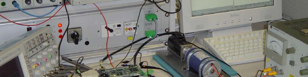

21 PMM Laboratory tudent Workbench 15-21
22 TI DMC Library Modules i as i αs αs qs qs αs i bs Clarke i βs βs Park ds ds In. Park βs Variable transformation from phase ab-axis to stationary αβ-axis θ λr Variable transformation from Variable transformation from stationary αβ-axis to synchronously rotating dq-axis to synchronously rotating dq-axis stationary αβ-axis θ λr αs βs pace Vector Gen. T a T b T c pace-ector generator producing the duty cycle ratio of PWM signals 15-22
23 TI DMC Library Modules i qs i qs PI qs QEP_A QEP_B QEP_ind QEP THETA DRV θ e θ m dir θ e dir PEED FRQ ω r Proportional-Integral controller QEP drier and shaft position and rotor direction peed estimation from rotor position and rotor direction T a T b T c PWM Drier PWM1 PWM2 PWM3 PWM4 PWM5 PWM6 ADCIN1 ADCIN2 ADCIN3 Ileg2_ Bus Drier i as i bs V dc PWM generation ADC drier for two line currents and DC-bus oltage measurement 15-23
24 Build Leel 1 Vq_testing αs T a PWM1 PWM2 Vd_testing In. Park βs pace Vector Gen. T b T c PWM Drier PWM3 PWM4 PWM5 PWM6 rmp_out speed_ref Ramp control Ramp Gen. key modules under test TM320F28x controller 15-24

 15-25")
25 Code Composer tudio with Real Time Mode 1. Load a workspace file pmsm3_1.wks 2. In build.h, #define BUILDLEVEL LEVEL1 3. Rebuild all 4. Load program to target (..\pmsm3_1.out) 15-25

26 Code Composer tudio with Real Time Mode 5. In Debug menu, Reset CPU and then set Real-time Mode. Then, click Yes when the message box pops up. 6. Click Run icon 15-26

27 Code Composer tudio with Real Time Mode 7. Right click on watch window. Then, check Continuous Refresh. 8. et enable_flg to 1 in watch window. (to enable T1UF interrupt and PWM drie on DMC550) 15-27

28 Code Composer tudio Leel 1 Changing!! watch window for build


29 Results: Build Leel 1 rmp_out Ta 15-29
30 Build Leel 2 Current erification Vq_testing αs T a PWM1 PWM2 Vd_testing In. Park θ e βs pace Vector Gen. T b T c PWM Drier PWM3 PWM4 PWM5 PWM6 Voltage ource Inerter i ds i qs Park i αs i βs Clarke i a i b Ileg2_ Bus Drier ADCIN1 ADCIN2 ADCIN3 peed_ref Ramp control Ramp Gen. rmp_out key module under test Encoder PMM TM320F28x controller 15-30
31 Instructions: Build Leel 2 1. Tune the 24V Power upply to 10 Volts with 1 Amp limit 2. Load a workspace file pmsm3_1.wks 3. In build.h, #define BUILDLEVEL LEVEL2 4. Reset CPU, Compile, Load, start RTM and Run 5. witch on 24V Power upply 6. et ariable enable_flg to 1 in watch window. 7. Try to change motor speed by setting speed_ref (p.u.) in watch window. Then, motor should change its speed accordingly

32 Results: Build Leel 2 1. PMM should run open-loop smoothly 2. The currents in the motor phases should be sinusoidal
33 Build Leel 3 - Tuning of dq-axis current closed loops key modules under test Iq_ref Id_ref i ds PI PI qs ds In. Park αs βs rmp_out pace Vector Gen. T a T b T c PWM Drier PWM1 PWM2 PWM3 PWM4 PWM5 PWM6 Voltage ource Inerter i ds i qs Park i αs i βs Clarke i a i b Ileg2_ Bus Drier ADCIN1 ADCIN2 ADCIN3 peed_ref Ramp control Ramp Gen. Encoder PMM TM320F28x controller 15-33
34 Instructions: Build Leel 3 1. In build.h, #define BUILDLEVEL LEVEL3 2. Compile, Load, start RTM and Run 3. et enable_flg to 1 in watch window. 4. Tune-up up the PI Obsere dq-axis current regulations at PI inputs (i.e., reference and feedback). For example, pid1_iq.pid_ pid1_iq.pid_ref_reg3 and pid1_iq.pid_ pid1_iq.pid_fdb_reg3. Try to change motor speed by setting speed_ref (p.u.) in watch window. Then, obsere dq-axis current regulations. ref fdb P I D out 15-34
35 Build Leel 4 Encoder erification Iq_ref Id_ref PI PI qs ds i ds i qs In. Park Park αs βs rmp_out i αs i βs pace Vector Gen. Clarke T a T b T c i a i b PWM Drier Ileg2_ Bus Drier PWM1 PWM2 PWM3 PWM4 PWM5 PWM6 ADCIN1 ADCIN2 ADCIN3 Voltage ource Inerter peed_ref Ramp control Ramp Gen. Theta_elec θ m dir QEP THETA DRV QEP_A QEP_B QEP_inc Encoder PMM TM320F28x controller 15-35
36 Instructions: Build Leel 4 1. In build.h, #define BUILDLEVEL LEVEL4 2. Compile, Load, start RTM and Run 3. et the DC-bus to 24 Volts 1 Amp 4. et enable_flg to 1 in watch window

37 Results: Build Leel 4 Emulated angle V sensed angle 15-37

38 Results: Build Leel 4 peed reference V real speed 15-38
39 Build Leel 5 close speed loop PI i qs i ds PI PI qs ds i ds i qs In. Park θ λr Park αs βs i αs i βs pace Vector Gen. Clarke T a T b T c i as i bs PWM Drier Ileg2_ Bus Drier PWM1 PWM2 PWM3 PWM4 PWM5 PWM6 ADCIN1 ADCIN2 ADCIN3 Voltage ource Inerter ω r PEED FRQ θ e dir QEP THETA DRV QEP_A QEP_B QEP_inc Encoder PMM TM320F28x controller 15-39
40 Instructions: Build Leel 5 1. In build.h, #define BUILDLEVEL LEVEL5 2. Compile, Load, start RTM and Run 3. et the DC-bus to 24 Volts 4. et enable_flg to 1 in watch window

41 Results: Build Leel 5 Fastest response time with the closed loop! 15-41


42 Application of PMM 3-1: 3 img GmbH Nordhausen 15-42


43
STM32 PMSM FOC SDK v3.2. 蒋建国 MCU Application Great China
 STM32 PMSM FOC SDK v3.2 蒋建国 MCU Application Great China Agenda 2 1 st day Morning Overview Key message Basics Feature Performance Hardware support Tools STM32 MC Workbench SDK components Architectural
A Practical Primer On Motor Drives (Part 13): Motor Drive Control Architectures And Algorithms
: Motor Drive Control Architectures And Algorithms") ISSUE: February 2017 A Practical Primer On Motor Drives (Part 13): Motor Drive Control Architectures And Algorithms by Ken Johnson, Teledyne LeCroy, Chestnut Ridge, N.Y. Part 12 began the explanation of
ISSUE: February 2017 A Practical Primer On Motor Drives (Part 13): Motor Drive Control Architectures And Algorithms by Ken Johnson, Teledyne LeCroy, Chestnut Ridge, N.Y. Part 12 began the explanation of
Sistemi per il controllo motori
 Sistemi per il controllo motori TALENTIS 4ª SESSIONE - 28 MAGGIO 2018 Speaker: Ing. Giuseppe Scuderi Automation and Motion control team Central Lab Prodotti ST per il controllo motori 2 Applicazioni e
Volume 1, Number 1, 2015 Pages Jordan Journal of Electrical Engineering ISSN (Print): , ISSN (Online):
: , ISSN (Online):") JJEE Volume, Number, 2 Pages 3-24 Jordan Journal of Electrical Engineering ISSN (Print): 249-96, ISSN (Online): 249-969 Analysis of Brushless DC Motor with Trapezoidal Back EMF using MATLAB Taha A. Hussein
JJEE Volume, Number, 2 Pages 3-24 Jordan Journal of Electrical Engineering ISSN (Print): 249-96, ISSN (Online): 249-969 Analysis of Brushless DC Motor with Trapezoidal Back EMF using MATLAB Taha A. Hussein
DMCode-MS(BL) MATLAB Library
 MATLAB Library") Technosoft is a Third Party of Texas Instruments supporting the TMS320C28xx and TMS320F24xx DSP controllers of the C2000 family To help you get your project started rapidly, Technosoft offers the DMCode-MS(BL)
Technosoft is a Third Party of Texas Instruments supporting the TMS320C28xx and TMS320F24xx DSP controllers of the C2000 family To help you get your project started rapidly, Technosoft offers the DMCode-MS(BL)
Sensored Field Oriented Control of 3-Phase Permanent Magnet Synchronous Motors
 Texas Instruments, Inc. C2000 Systems and Applications Sensored Field Oriented Control of 3-Phase Permanent Magnet Synchronous Motors Authors: Bilal Akin, Manish Bhardwaj Contents Introduction... 3 PMSM
Three-Phase Induction Motors. By Sintayehu Challa ECEg332:-Electrical Machine I
 Three-Phase Induction Motors 1 2 3 Classification of AC Machines 1. According to the type of current Single Phase and Three phase 2. According to Speed Constant Speed, Variable Speed and Adjustable Speed
Digital Control of Permanent Magnet Synchronous Motor
 Digital Control of Permanent Magnet Synchronous Motor Jayasri R. Nair 1 Assistant Professor, Dept. of EEE, Rajagiri School Of Engineering and Technology, Kochi, Kerala, India 1 ABSTRACT: The principle
A COMPARISON STUDY OF THE COMMUTATION METHODS FOR THE THREE-PHASE PERMANENT MAGNET BRUSHLESS DC MOTOR
 A COMPARISON STUDY OF THE COMMUTATION METHODS FOR THE THREE-PHASE PERMANENT MAGNET BRUSHLESS DC MOTOR Shiyoung Lee, Ph.D. Pennsylvania State University Berks Campus Room 120 Luerssen Building, Tulpehocken
User Guide IRMCS3041 System Overview/Guide. Aengus Murray. Table of Contents. Introduction
 User Guide 0607 IRMCS3041 System Overview/Guide By Aengus Murray Table of Contents Introduction... 1 IRMCF341 Application Circuit... 2 Sensorless Control Algorithm... 4 Velocity and Current Control...
TUTORIAL Simulation and Code Generation of TI InstaSPIN Using DRV8312 EVM
 TUTORIAL Simulation and Code Generation of TI InstaSPIN Using DRV8312 EVM January 2017 1 PSIM supports TI s InstaSPIN FOC sensorless motor control algorithm in simulation and SimCoder auto code generation.
RX23T inverter ref. kit
 RX23T inverter ref. kit Deep Dive October 2015 YROTATE-IT-RX23T kit content Page 2 YROTATE-IT-RX23T kit: 3-ph. Brushless Motor Specs Page 3 Motors & driving methods supported Brushless DC Permanent Magnet
2014 Texas Instruments Motor Control Training Series. -V th. Dave Wilson
 2014 Texas Instruments Motor Control Training Series -V th Evolution of Sensorless Drive Technology March, 2013 InstaSPIN-FOC Saliency Tracking Direct Torque Control Sliding Mode Observers Linear Observers
Analog Devices: High Efficiency, Low Cost, Sensorless Motor Control.
 Analog Devices: High Efficiency, Low Cost, Sensorless Motor Control. Dr. Tom Flint, Analog Devices, Inc. Abstract In this paper we consider the sensorless control of two types of high efficiency electric
User Guide Introduction. IRMCS3043 System Overview/Guide. International Rectifier s imotion Team. Table of Contents
 User Guide 08092 IRMCS3043 System Overview/Guide By International Rectifier s imotion Team Table of Contents IRMCS3043 System Overview/Guide... 1 Introduction... 1 IRMCF343 Application Circuit... 2 Power
CHAPTER 6 CURRENT REGULATED PWM SCHEME BASED FOUR- SWITCH THREE-PHASE BRUSHLESS DC MOTOR DRIVE
 125 CHAPTER 6 CURRENT REGULATED PWM SCHEME BASED FOUR- SWITCH THREE-PHASE BRUSHLESS DC MOTOR DRIVE 6.1 INTRODUCTION Permanent magnet motors with trapezoidal back EMF and sinusoidal back EMF have several
STM32 motor control firmware library. STM32 FOC PMSM SDK v3.0.
 STM32 motor control firmware library STM32 FOC PMSM SDK v3.0 Contents STM32 FOC PMSM SDK v3.0 overview The FOC (field oriented control) algorithm STM32 with FOC Motor control and electric motor offer FOC
AN Sensorless single-shunt FOC on LPC2900. Document information. LPC2900, FOC, SVPWM, SMC, current observer, PMSM, single shunt DC-link
 Sensorless single-shunt Rev. 01 16 December 2009 Application note Document information Info Keywords Abstract Content LPC2900, FOC, SVPWM, SMC, current observer, PMSM, single shunt DC-link This application
InstaSPIN-BLDC Lab. DRV8312 Setup Jumpers and switches must be setup properly or the kit will not function correctly!
 InstaSPIN-BLDC Lab Introduction For this lab we are using the DRV8312 Low Voltage, Low Current Power Stage (the DRV8301/2 Kit can also be used) with Piccolo F28035 controlcard to run the sensorless InstaSPIN-BLDC
CHAPTER-III MODELING AND IMPLEMENTATION OF PMBLDC MOTOR DRIVE
 CHAPTER-III MODELING AND IMPLEMENTATION OF PMBLDC MOTOR DRIVE 3.1 GENERAL The PMBLDC motors used in low power applications (up to 5kW) are fed from a single-phase AC source through a diode bridge rectifier
2013 Texas Instruments Motor Control Training Series. -V th. InstaSPIN Training
 2013 Texas Instruments Motor Control Training Series -V th InstaSPIN Training How Do You Control Torque on a DC Motor? Brush DC Motor Desire Current + - Error Signal PI Controller PWM Power Stage Texas
A Dynamic Modeling Permanent Magnet Synchronous Motor Drive System
 A Dynamic Modeling Permanent Magnet Synchronous Motor Drive System MISS. KINJAL G. PATEL P.G. Student, Department of Electrical Engineering SSSRGI, Vadasma, Mehsana MR. CHIRAG V. PATEL Assistant Professor,
Example Data for Electric Drives Experiment 6. Analysis and Control of a Permanent Magnet AC (PMAC) Motor
 Motor") Example Data for Electric Drives Experiment 6 Analysis and Control of a Permanent Magnet AC (PMAC) Motor The intent of this document is to provide example data for instructors and TAs, to help them prepare
Example Data for Electric Drives Experiment 6 Analysis and Control of a Permanent Magnet AC (PMAC) Motor The intent of this document is to provide example data for instructors and TAs, to help them prepare
TUTORIAL Simulation and Code Generation with TI InstaSPIN Block
 TUTORIAL Simulation and Code Generation with TI InstaSPIN Block November 2016 1 PSIM supports TI s InstaSPIN FOC sensorless motor control algorithm in simulation and SimCoder auto code generation. With
CURRENT FOLLOWER APPROACH BASED PI AND FUZZY LOGIC CONTROLLERS FOR BLDC MOTOR DRIVE SYSTEM FED FROM CUK CONVERTER
 CURRENT FOLLOWER APPROACH BASED PI AND FUZZY LOGIC CONTROLLERS FOR BLDC MOTOR DRIVE SYSTEM FED FROM CUK CONVERTER N. Mohanraj and R. Sankaran Shanmugha Arts, Science, Technology and Research Academy University,
Vector Control of a 3-Phase PMSM Using the ZNEO Z16FMC MCU
 MultiMotor Series Application Note Vector Control of a 3-Phase PMSM Using the ZNEO Z16FMC MCU AN039402-0816 Abstract Brushed DC machines are widely popular due to their simplicity, ease of control and
CHAPTER 6 UNIT VECTOR GENERATION FOR DETECTING VOLTAGE ANGLE
 98 CHAPTER 6 UNIT VECTOR GENERATION FOR DETECTING VOLTAGE ANGLE 6.1 INTRODUCTION Process industries use wide range of variable speed motor drives, air conditioning plants, uninterrupted power supply systems
Design of A Closed Loop Speed Control For BLDC Motor
 International Refereed Journal of Engineering and Science (IRJES) ISSN (Online) 2319-183X, (Print) 2319-1821 Volume 3, Issue 11 (November 214), PP.17-111 Design of A Closed Loop Speed Control For BLDC
L E C T U R E R, E L E C T R I C A L A N D M I C R O E L E C T R O N I C E N G I N E E R I N G
 P R O F. S L A C K L E C T U R E R, E L E C T R I C A L A N D M I C R O E L E C T R O N I C E N G I N E E R I N G G B S E E E @ R I T. E D U B L D I N G 9, O F F I C E 0 9-3 1 8 9 ( 5 8 5 ) 4 7 5-5 1 0
CHAPTER-5 DESIGN OF DIRECT TORQUE CONTROLLED INDUCTION MOTOR DRIVE
 113 CHAPTER-5 DESIGN OF DIRECT TORQUE CONTROLLED INDUCTION MOTOR DRIVE 5.1 INTRODUCTION This chapter describes hardware design and implementation of direct torque controlled induction motor drive with
Sensored Field Oriented Control of 3-Phase Permanent Magnet Synchronous Motors
 Sensored Field Oriented Control of 3-Phase Permanent Magnet Synchronous Motors Bilal Akin Manish Bhardwaj C2000 Systems and Applications Team Abstract This application note presents a solution to control
MATLAB/SIMULINK MODEL OF FIELD ORIENTED CONTROL OF PMSM DRIVE USING SPACE VECTORS
 MATLAB/SIMULINK MODEL OF FIELD ORIENTED CONTROL OF PMSM DRIVE USING SPACE VECTORS Remitha K Madhu 1 and Anna Mathew 2 1 Department of EE Engineering, Rajagiri Institute of Science and Technology, Kochi,
Induction motor control by vector control method.
 International Refereed Journal of Engineering and Science (IRJES) e- ISSN :2319-183X p-issn : 2319-1821 On Recent Advances in Electrical Engineering Induction motor control by vector control method. Miss.
A Complete Implementation Procedure for State Estimation in Induction Machines on the ezdsp F2812. Ali M. Bazzi and Philip T.
 A Complete Implementation Procedure for State Estimation in Induction Machines on the ezdsp F2812 Ali M. Bazzi and Philip T. Krein Grainger Center for Electric Machinery and Electromechanics Department
Sensorless Vector Control and Implementation: Why and How
 Sensorless Vector Control and Implementation: Why and How Renesas Electronics America Inc. Renesas Technology & Solution Portfolio 2 Microcontroller and Microprocessor Line-up 2010 2013 32-bit 8/16-bit
New Direct Torque Control of DFIG under Balanced and Unbalanced Grid Voltage
 1 New Direct Torque Control of DFIG under Balanced and Unbalanced Grid Voltage B. B. Pimple, V. Y. Vekhande and B. G. Fernandes Department of Electrical Engineering, Indian Institute of Technology Bombay,
SPEED CONTROL OF INDUCTION MOTOR WITHOUT SPEED SENSOR AT LOW SPEED OPERATIONS
 SPEED CONTROL OF INDUCTION MOTOR WITHOUT SPEED SENSOR AT LOW SPEED OPERATIONS Akshay Prasad Dubey and Saravana Kumar R. School of Electrical Engineering, VIT University, Vellore, Tamil Nadu, India E-Mail:
AC Drive Technology. An Overview for the Converting Industry. Siemens Industry, Inc All rights reserved.
 AC Drive Technology An Overview for the Converting Industry www.usa.siemens.com/converting Siemens Industry, Inc. 2016 All rights reserved. Answers for industry. AC Drive Technology Drive Systems AC Motors
EE 560 Electric Machines and Drives. Autumn 2014 Final Project. Contents
 EE 560 Electric Machines and Drives. Autumn 2014 Final Project Page 1 of 53 Prof. N. Nagel December 8, 2014 Brian Howard Contents Introduction 2 Induction Motor Simulation 3 Current Regulated Induction
Impact of PWM Control Frequency onto Efficiency of a 1 kw Permanent Magnet Synchronous Motor
 http://dx.doi.org/10.5755/j01.eie.22.6.17216 ELEKTRONIKA IR ELEKTROTECHNIKA, ISSN 1392-1215, VOL. 22, NO. 6, 2016 Impact of PWM Control Frequency onto Efficiency of a 1 kw Permanent Magnet Synchronous
Reduction of Harmonics and Torque Ripples of BLDC Motor by Cascaded H-Bridge Multi Level Inverter Using Current and Speed Control Techniques
 Reduction of Harmonics and Torque Ripples of BLDC Motor by Cascaded H-Bridge Multi Level Inverter Using Current and Speed Control Techniques A. Sneha M.Tech. Student Scholar Department of Electrical &
FPGA-based field-oriented control for induction motor speed drive
 FPGA-based field-oriented control for induction motor speed drive C. P. Ooi 1a),W.P.Hew 2,N.A.Rahim 2, and L. C. Kuan 1 1 Faculty of Engineering, Multimedia University, Jalan Multimedia, 63100 Cyberjaya
ECE 5670/ Lab 5. Closed-Loop Control of a Stepper Motor. Objectives
 1. Introduction ECE 5670/6670 - Lab 5 Closed-Loop Control of a Stepper Motor Objectives The objective of this lab is to develop and test a closed-loop control algorithm for a stepper motor. First, field
CHAPTER 4 FUZZY BASED DYNAMIC PWM CONTROL
 47 CHAPTER 4 FUZZY BASED DYNAMIC PWM CONTROL 4.1 INTRODUCTION Passive filters are used to minimize the harmonic components present in the stator voltage and current of the BLDC motor. Based on the design,
HIGH PERFORMANCE CONTROL OF AC DRIVES WITH MATLAB/SIMULINK MODELS
 HIGH PERFORMANCE CONTROL OF AC DRIVES WITH MATLAB/SIMULINK MODELS Haitham Abu-Rub Texas A&M University at Qatar, Qatar Atif Iqbal Qatar University, Qatar and Aligarh Muslim University, India Jaroslaw Guzinski
TRACK VOLTAGE APPROACH USING CONVENTIONAL PI AND FUZZY LOGIC CONTROLLER FOR PERFORMANCE COMPARISON OF BLDC MOTOR DRIVE SYSTEM FED BY CUK CONVERTER
 International Journal of Mechanical Engineering and Technology (IJMET) Volume 9, Issue 12, December 2018, pp. 778 786, Article ID: IJMET_09_12_078 Available online at http://www.ia aeme.com/ijmet/issues.asp?jtype=ijmet&vtype=
CHAPTER 2 CURRENT SOURCE INVERTER FOR IM CONTROL
 9 CHAPTER 2 CURRENT SOURCE INVERTER FOR IM CONTROL 2.1 INTRODUCTION AC drives are mainly classified into direct and indirect converter drives. In direct converters (cycloconverters), the AC power is fed
Sensorless Vector Control with RL78G14
 Sensorless Vector Control with RL78G14 Renesas Electronics America Inc. Renesas Technology & Solution Portfolio 2 Microcontroller and Microprocessor Line-up 2010 2013 32-bit 8/16-bit 1200 DMIPS, Superscalar
3KDVH 6LQH *HQHUDWRU ZLWK 9DULDEOH3KDVH&RQWURO
 Digital Motor Control Library 3KDVH 6LQH *HQHUDWRU ZLWK 9DULDEOH3KDVH&RQWURO Component Name: 2-Phase Sine Generator with Variable Phase Control 2-Phase Sine Generator with Variable Phase Control 0 Inputs
3.1.Introduction. Synchronous Machines
 3.1.Introduction Synchronous Machines A synchronous machine is an ac rotating machine whose speed under steady state condition is proportional to the frequency of the current in its armature. The magnetic
Motor control using FPGA
 Motor control using FPGA MOTIVATION In the previous chapter you learnt ways to interface external world signals with an FPGA. The next chapter discusses digital design and control implementation of different
SPEED CONTROL OF BRUSHLESS DC MOTOR USING FUZZY BASED CONTROLLERS
 SPEED CONTROL OF BRUSHLESS DC MOTOR USING FUZZY BASED CONTROLLERS Kapil Ghuge 1, Prof. Manish Prajapati 2 Prof. Ashok Kumar Jhala 3 1 M.Tech Scholar, 2 Assistant Professor, 3 Head of Department, R.K.D.F.
A Comparative Study of Sinusoidal PWM and Space Vector PWM of a Vector Controlled BLDC Motor
 A Comparative Study of Sinusoidal PWM and Space Vector PWM of a Vector Controlled BLDC Motor Lydia Anu Jose 1, K. B.Karthikeyan 2 PG Student, Dept. of EEE, Rajagiri School of Engineering and Technology,
CHAPTER 2 VSI FED INDUCTION MOTOR DRIVE
 CHAPTER 2 VI FE INUCTION MOTOR RIVE 2.1 INTROUCTION C motors have been used during the last century in industries for variable speed applications, because its flux and torque can be controlled easily by
Robust BDCM Sensorless Control With Position-Dependent Load Torque
 Robust BDCM ensorless Control With Position-Dependent Load Torque Chih-Kai uang, Pei-Yu,Yu, ung-chi Chen (IEEE Member), Industrial Technology Research Institute, sinchu, Taiwan. Jeff.uang@itri.org.tw Department
An Induction Motor Control by Space Vector PWM Technique
 An Induction Motor Control by Space Vector PWM Technique Sanket Virani PG student Department of Electrical Engineering, Sarvajanik College of Engineering & Technology, Surat, India Abstract - This paper
Sensorless Field Oriented Control of 3-Phase Permanent Magnet Synchronous Motors
 Sensorless Field Oriented Control of 3-Phase Permanent Magnet Synchronous Motors C2000 Systems and Applications Team Abstract This application note presents a solution to control a permanent magnet synchronous
Robot Actuators. Motors and Control. Stepper Motor Basics. Increased Resolution. Stepper motors. DC motors AC motors. Physics review: Nature is lazy.
 obot Actuators tepper motors Motors and Control DC motors AC motors Physics review: ature is lazy. Things seek lowest energy states. iron core vs. magnet magnetic fields tend to line up Electric fields
CHAPTER 6 THREE-LEVEL INVERTER WITH LC FILTER
 97 CHAPTER 6 THREE-LEVEL INVERTER WITH LC FILTER 6.1 INTRODUCTION Multi level inverters are proven to be an ideal technique for improving the voltage and current profile to closely match with the sinusoidal
PMSM Control Using a Three-Phase, Six-Step 120 Modulation Inverter
 Exercise 1 PMSM Control Using a Three-Phase, Six-Step 120 Modulation Inverter EXERCISE OBJECTIVE When you have completed this exercise, you will be familiar with six-step 120 modulation. You will know
AN2290 Application note Flux control simulink and software library of a PMSM Introduction
 Application note Flux control simulink and software library of a PMSM Introduction This application note describes a software library for the electric motor control implementing a (FOC) Flux Oriented Control
10kW Three-phase SiC PFC Rectifier
 www.onsemi.com 10kW Three-phase SiC PFC Rectifier SEMICON EUROPA, Nov 13-18, 2018, Munich, Germany Contents General PFC Concept 3 Phase System and PFC Control Simulation Understanding the losses 3 Phase
Using CME 2 with AccelNet
 Using CME 2 with AccelNet Software Installation Quick Copy (with Amplifier file) Quick Setup (with motor data) Offline Virtual Amplifier (with no amplifier connected) Screen Guide Page 1 Table of Contents
Synchronous Machines Study Material
 Synchronous machines: The machines generating alternating emf from the mechanical input are called alternators or synchronous generators. They are also known as AC generators. All modern power stations
The Implementation of Field Oriented Control for PMSM Drive Based on TMS320F28035 DSP Controller
 The Implementation of Field Oriented Control for PMSM Drive Based on TMS30F8035 DSP Controller Roopa C 1 and Dr. S. Sujitha 1, Department of Electrical and Electronics Engineering, New Horizon College
A Modified Sychronous Current Regulator for Brushless Motor Control
 A Modified Sychronous Current Regulator for Brushless Motor Control Shane Colton Graduate Student, Department of Mechanical Engineering Massachusetts Institute of Technology Rev0 - Doctoral
The University of Wisconsin-Platteville
 Embedded Motor Drive Development Platform for Undergraduate Education By: Nicholas, Advisor Dr. Xiaomin Kou This research and development lead to the creation of an Embedded Motor Drive Prototyping station
Electric Bike BLDC Hub Motor Control Using the Z8FMC1600 MCU
 Application Note Electric Bike BLDC Hub Motor Control Using the Z8FMC1600 MCU AN026002-0608 Abstract This application note describes a controller for a 200 W, 24 V Brushless DC (BLDC) motor used to power
ELE847 Advanced Electromechanical Systems Course Notes 2008 Edition
 Department of Electrical and Computer Engineering ELE847 Advanced Electromechanical Systems Course Notes 2008 Edition ELE847 Advanced Electromechanical Systems Table of Contents 1. Course Outline.... 1
IN MANY industrial applications, ac machines are preferable
 IEEE TRANSACTIONS ON INDUSTRIAL ELECTRONICS, VOL. 46, NO. 1, FEBRUARY 1999 111 Automatic IM Parameter Measurement Under Sensorless Field-Oriented Control Yih-Neng Lin and Chern-Lin Chen, Member, IEEE Abstract
Introduction to BLDC Motor Control Using Freescale MCU. Tom Wang Segment Biz. Dev. Manager Avnet Electronics Marketing Asia
 Introduction to BLDC Motor Control Using Freescale MCU Tom Wang Segment Biz. Dev. Manager Avnet Electronics Marketing Asia Agenda Introduction to Brushless DC Motors Motor Electrical and Mechanical Model
The DC Machine Laboration 3
 EIEN25 - Power Electronics: Devices, Converters, Control and Applications The DC Machine Laboration 3 Updated February 19, 2018 1. Before the lab, look through the manual and make sure you are familiar
High-speed and High-precision Motion Controller
 High-speed and High-precision Motion Controller - KSMC - Definition High-Speed Axes move fast Execute the controller ( position/velocity loop, current loop ) at high frequency High-Precision High positioning
One-line Detection of Rotor Position for Vector Controlled IPMSM
 One-line Detection of Rotor Position for Vector Controlled IPMSM Topic number: T2 Abstract Conventional vector control of IPMSM requires a motor position sensor to correctly orient the current vector orthogonally
Bakiss Hiyana binti Abu Bakar JKE, POLISAS BHAB
 1 Bakiss Hiyana binti Abu Bakar JKE, POLISAS 1. Explain AC circuit concept and their analysis using AC circuit law. 2. Apply the knowledge of AC circuit in solving problem related to AC electrical circuit.
Speed Control of Brushless DC Motor Using Fuzzy Based Controllers
 Speed Control of Brushless DC Motor Using Fuzzy Based Controllers Harith Mohan 1, Remya K P 2, Gomathy S 3 1 Harith Mohan, P G Scholar, EEE, ASIET Kalady, Kerala, India 2 Remya K P, Lecturer, EEE, ASIET
DSP Based Speed Control of the Surface Mounted Permanent Magnet Synchronous Motor with Hysteresis current controller
 DSP Based Speed Control of the Surface Mounted Permanent Magnet Synchronous Motor with Hysteresis current controller ABDEL-KARIM DAUD Electrical and Computer Engineering Department Palestine Polytechnic
Module 7. Electrical Machine Drives. Version 2 EE IIT, Kharagpur 1
 Module 7 Electrical Machine Drives Version 2 EE IIT, Kharagpur 1 Lesson 34 Electrical Actuators: Induction Motor Drives Version 2 EE IIT, Kharagpur 2 Instructional Objectives After learning the lesson
SPEED CONTROL OF PERMANENT MAGNET SYNCHRONOUS MOTOR USING VOLTAGE SOURCE INVERTER
 SPEED CONTROL OF PERMANENT MAGNET SYNCHRONOUS MOTOR USING VOLTAGE SOURCE INVERTER Kushal Rajak 1, Rajendra Murmu 2 1,2 Department of Electrical Engineering, B I T Sindri, (India) ABSTRACT This paper presents
Code No: R Set No. 1
 Code No: R05310204 Set No. 1 III B.Tech I Semester Regular Examinations, November 2007 ELECTRICAL MACHINES-III (Electrical & Electronic Engineering) Time: 3 hours Max Marks: 80 Answer any FIVE Questions
National Infotech. Electrical Drive Trainers. Developed By: : Authorized Dealer : Embedded System Solutions
 National Infotech A way to Power Electronics and Embedded System Solutions Electrical Drive Trainers In every industry there are industrial processes where electrical motors are used as a part of process
CHAPTER 4 CONTROL ALGORITHM FOR PROPOSED H-BRIDGE MULTILEVEL INVERTER
 65 CHAPTER 4 CONTROL ALGORITHM FOR PROPOSED H-BRIDGE MULTILEVEL INVERTER 4.1 INTRODUCTION Many control strategies are available for the control of IMs. The Direct Torque Control (DTC) is one of the most
Chapter 2 MODELING AND CONTROL OF PEBB BASED SYSTEMS
 Chapter 2 MODELING AND CONTROL OF PEBB BASED SYSTEMS 2.1 Introduction The PEBBs are fundamental building cells, integrating state-of-the-art techniques for large scale power electronics systems. Conventional
Speed control of three phase induction motor drive using SVPWM control scheme
 Speed control of three phase induction motor drive using SVPWM control scheme 1 Gajjar Jahnavibahen B., 2 Mr.Ghanshyam Gajjar 1 MEPEED Student, Dept. of Electrical Engineering, MEFGI, Rajkot, 2 SR. Engineer,
Motor Control using NXP s LPC2900
 Motor Control using NXP s LPC2900 Agenda LPC2900 Overview and Development tools Control of BLDC Motors using the LPC2900 CPU Load of BLDCM and PMSM Enhancing performance LPC2900 Demo BLDC motor 2 LPC2900
Modelling and Simulation of a DC Motor Drive
 Modelling and Simulation of a DC Motor Drive 1 Introduction A simulation model of the DC motor drive will be built using the Matlab/Simulink environment. This assignment aims to familiarise you with basic
Implementation of Brushless DC motor speed control on STM32F407 Cortex M4
 Implementation of Brushless DC motor speed control on STM32F407 Cortex M4 Mr. Kanaiya G Bhatt 1, Mr. Yogesh Parmar 2 Assistant Professor, Assistant Professor, Dept. of Electrical & Electronics, ITM Vocational
Nicolò Antonante Kristian Bergaplass Mumba Collins
 Norwegian University of Science and Technology TET4190 Power Electronics for Renewable Energy Mini-project 19 Power Electronics in Motor Drive Application Nicolò Antonante Kristian Bergaplass Mumba Collins
Chapter 12 DSP-BASED CONTROL OF PERMANENT MAGNET SYNCHRONOUS MACHINES
 Chapter 1 DSP-BASED CONTROL OF PERMANENT MAGNET SYNCHRONOUS MACHINES 1.1 Introduction As described in Chapter 9, the permanent magnet synchronous motor (PMSM) is a PM motor with a sinusoidal back-emf.
Implementation of discretized vector control strategies for induction machines
 Implementation of discretized vector control strategies for induction machines Report of Master of Science thesis Prepared By Md. Inoon Nishat Amalesh Chowdhury Department of Energy and Environment Division
Speed control of sensorless BLDC motor with two side chopping PWM
 IOSR Journal of Electrical and Electronics Engineering (IOSR-JEEE) e-issn: 2278-1676,p-ISSN: 2320-3331, Volume 6, Issue 3 (May. - Jun. 2013), PP 16-20 Speed control of sensorless BLDC motor with two side
MATHEMATICAL SIMULATION OF THE ASYNCHRONOUS ELECTRIC DRIVE OF PERIODIC MOVEMENT
 MATHEMATICAL SIMULATION OF THE ASYNCHRONOUS ELECTRIC DRIVE OF PERIODIC MOVEMENT Vasiliy O. Nagorniy 1, and Anatoliy V. Aristov 1,* 1 Tomsk Polytechnic University, 634050, Tomsk, Russia Abstract. The article
Modeling and Simulation of Induction Motor Drive with Space Vector Control
 Australian Journal of Basic and Applied Sciences, 5(9): 2210-2216, 2011 ISSN 1991-8178 Modeling and Simulation of Induction Motor Drive with Space Vector Control M. SajediHir, Y. Hoseynpoor, P. MosadeghArdabili,
GENERAL OVERVIEW OF HOW POWER ELECTRONICS WORK. Pana Shenoy Calnetix Technologies, LLC Cerritos, CA, USA
 GNL OVVIW OF HOW POW LCTONICS WOK Pana Shenoy Calnetix Technologies, LLC Cerritos, C, US Calnetix s Vericycle Bidirectional Drives typically interface with highspeed Permanent Magnet Synchronous Machines
ROTOR FLUX VECTOR CONTROL TRACKING FOR SENSORLESS INDUCTION MOTOR
 International Journal of Scientific & Engineering Research, Volume 7, Issue 4, April-2016 668 ROTOR FLUX VECTOR CONTROL TRACKING FOR SENSORLESS INDUCTION MOTOR Fathima Farook 1, Reeba Sara Koshy 2 Abstract
International Journal of Advance Engineering and Research Development
 Scientific Journal of Impact Factor (SJIF): 4.72 International Journal of Advance Engineering and Research Development Volume 4, Issue 4, April -217 e-issn (O): 2348-447 p-issn (P): 2348-646 Analysis,
Smooth rotation. An adaptive algorithm kills jerky motions in motors.
 Page 1 of 4 Copyright 2004 Penton Media, Inc., All rights reserved. Printing of this document is for personal use only. For reprints of this or other articles, click here Smooth rotation An adaptive algorithm
TUTORIAL Simulation and Code Generation of TI InstaSPIN Using DRV8312 EVM
 TUTORIAL Simulation and Code Generation of TI InstaSPIN Using DR8312 EM October 2017 1 Simulation and Code Generation of TI InstaSPIN Using DR8312 EM PSIM supports TI s InstaSPIN-FOC sensorless motor control
Dissertation Doctor of Engineering
 Dissertation Doctor of Engineering Fully FPGA-Based Permanent Magnet Synchronous Motor Speed Control System Using Two-Degrees-of- Freedom Method Designed by Fictitious Reference Iterative Tuning By Charles
A Robust Fuzzy Speed Control Applied to a Three-Phase Inverter Feeding a Three-Phase Induction Motor.
 A Robust Fuzzy Speed Control Applied to a Three-Phase Inverter Feeding a Three-Phase Induction Motor. A.T. Leão (MSc) E.P. Teixeira (Dr) J.R. Camacho (PhD) H.R de Azevedo (Dr) Universidade Federal de Uberlândia