10kW Three-phase SiC PFC Rectifier
|
|
|
- Hannah Dennis
- 5 years ago
- Views:
Transcription

1 10kW Three-phase SiC PFC Rectifier SEMICON EUROPA, Nov 13-18, 2018, Munich, Germany
2 Contents General PFC Concept 3 Phase System and PFC Control Simulation Understanding the losses 3 Phase PFC Implementation Results 2 2/2/2018
3 General PFC Concept 3 2/2/2018
4 Definition of Power Factor φ 1 Real Power (W) V I Reactive Power (VAR) PF Real Power (W) Apparent Power (VA) I V POWER FACTOR V P RMS avg I RMS I I V I 1, RMS RMS cos 1 DISPLACEMENT FACTOR DISTORTION FACTOR cos( 1 ) DISTORTION FACTOR = DISPLACEMENT DISPLAC. FACTOR FACTOR = 0.96 = 1 PF = DIODE PFC TARGET BRIDGE DISTORTION FACTOR = 1 DISPLACEMENT FACTOR < 1 PF < 1 DISTORTION FACTOR < 1 DISPLACEMENT FACTOR = 1 PF < 1
5 3 Phase System and PFC Control 5 2/2/2018
6 3-phase PFC: Selected Topology Power Flow 3 Half Bridges. Each half bridge connected to a input phase voltage. Input voltages form a unique system. The 3-phase PFC control concept works as an inverter for motor application. Only the control strategy changes. This configuration would allow to control the reactive power because of Q axis availability.
7 3 Phase PFC: Voltage Relationship, ABC Model N σ i=a,b,c E im =0 E V LA AN V N0 d 1 d 2 d 3 A V A0 B C V DC 0 SYSTEM VOLTAGE EQUATIONS IN ABC DOMAIN v v v L, A L, B L, C e e e AN BN CN u u u N 0 N 0 N 0 V V V A0 B0 C0 dia L R i S S A dt dib L R i S S B dt dic L R i S S C dt Goal of the PFC is to control the voltage across the inductors. SUPPLY VOLTAGE E AM = തE cos(ωt) E BM = തE cos(ωt 2 3 π) E CM = തE cos(ωt 4 3 π) TIME E A (t 1 ) E B (t 1 ) E C (t 1 ) B C E A,(t1) E S E C,(t1) E B,(t1) A VECTOR SPACE
8 Bus Voltage Limitation and Driving Capability SAH SBH SCH V DC When the switches are modulating, the following vectors can be provided in the vector space domain. E S,MAX = 0.57 V DC SAL SBL SCL VOLTAGE SOURCE INVERTER When FETs are left OPEN, the HW is operating as a diode bridge because of the FWD. The target DC BUS voltage has to be higher than the line to line voltage amplitude: V DC = 6E RMS,PHASE
9 System Reference: From 3φ Stationary To 2φ Rotating GEOMETRIC TIME B B β D β E B,(t1) E S E C,(t1) E A,(t1) A E S φ A α Φ = 0 E S θ α C CLARKE C PARK (αβ) = [T 0 ] (ABC) (DQ) = [T θ S ] (αβ) Q EAM EBM ECM Eα Eβ ED EQ ϑ [rad] -400 ϑ [rad] ϑ [rad]

10 3 Phase PFC: (DQ) Model di e L D S dt diq e L Q S dt dudc C dt D R R i D S S s i i D D Q L i L ELECTRICAL QUANTITIES ON DQ DOMAIN ARE CONSTANT VALUES Q s Q S S i i Q D V V u R DC L D Q Input quantities are transformed by means of Clarke/Park matrix. E D E Q are the supply voltages expressed in the DQ domain. i D, i Q are the phase currents in the DQ domain. ω is the fundamental frequency of the input voltage. V D and V Q are the voltage generated by the control in the DQ domain that will be used for the PWM generation. 10 2/2/2018
11 3 Phase PFC Control Scheme on DQ Domain SPECIFICATION Input voltage: 230V RMS 3-Phase voltage, 50Hz. Output Voltage: 700V 3 MODULATION STRATEGIES TESTED Switching Frequency: 70kHz Control Frequency: 20kHz Source Inductance: 300uH Output capacitance: 470uF CONTROL ALGORITHM FIXED DURING TEST CONDITIONS DQ SYSTEM MAKES PI REGULATION POSSIBLE! Ref. Fig Control in power electronics Author. M.P. Kazmierkowski et al. 2002

12 3 Phase PFC: Applied Modulation Strategies PWM Adaptive Modulator A modification into the zero sequence voltage doesn t affect the voltage applied to the inverter phases, however it will affect noise between DC output and PE. An impact on the input filter should be expected, even if in this presentation EMI FILTER was not considered. 12 2/2/2018
13 Simulations 13 2/2/2018

14 3 Phase PFC Simulink Model, Behavioral PARAMETERS F CLK = 84 Mhz 70kh pwm freq F PWM = 70 Khz F CNTR = 20 Khz ADC & PWM Peripherals DEAD TIME = 1.1% HARDWARE L S = 300 uh R S = 0,04 Ohm R HL = 72 Ohm ANALOG INPUTS Control Strategy (C-code) PWM OUTPUT R FL = 36 Ohm

15 3 Phase PFC SPICE Model, Quantitative CONTROL STRATEGY POWER STAGE SENSING INPUTS THE PARAMETERS SELECTED FOR RUNNING SPICE SIMULATION WERE ALIGNED WITH THE SIMULINK ONES.
16 Understanding the Losses 16 2/2/2018
17 Choke Inductor Losses (simplified) 700V P L,CORE = k f a Bc PK I X V LX L X X E XN (t) k, a and c are core material dependent. N f is the high switching frequency B PK is half the flux density ripple calculated considering the current ripple introduced by the inductance selected B PK = μ 0 μ R N I. 2 P L,JOULE = R W I 2 RMS Where R W is the winding resistance. I RMS is the circulating current for a certain power level with a known input voltage. 0 V X0
18 FETs Losses in Space Vector Modulation (1/2) t DT ia d A M D1 M1 D1 M2 ib ic d B D M3 D4 M1 M3 M d C D6 M5 D6 d A d B d C T PWM ia ib ic d' A A M2 d' B B M4 d' C C M6 HARD ON OFF HARD OFF ON SOFT ON - OFF SOFT OFF ON LEG A M2 - [1] M2 - [4] M1 - [3] M1 - [2] LEG B M3 [3] M3 [2] M4 [1] M4 [4] LEG C (as B) M5 [3] M4 [2] M6 [1] M4 [4] SWITCHING LOSSES P L,SW f PWM Notes During t DT both switches on each leg are fully OFF. FETs are bidirectional when turned ON and current flows according source and drain voltage potential. va is depending on phase voltage and star voltage when low side FET OFF and current into the node.
19 FETs Losses in Space Vector Modulation (2/2) P SW = 3 E OFF + E ON f PWM Note By designing a different modulation strategy, the number of transitions could be decreased by 33% and together with an appropriate timing based on current amplitude, a switching loss minimization can be achieved Since all the FETs are equal we simplify the calculation with the following formula P J = 3 R DS,ON T I2 RMS
20 3 Phase PFC Implementation 20 2/2/2018
21 3 Phase PFC Power Board Concept (1/2) Note: V BUS,MIN = = 650V 3V3 15V 3V3 15V 3V3 15V 700V 24V PWM EN FAULT ISO-GATE DRIVER PWM EN FAULT ISO-GATE DRIVER PWM EN FAULT ISO-GATE DRIVER vbus va ia CURR SEN. vb ib CURR. SEN. vc ic CURR. SEN. 24V 3V3 15V 3V3 15V 3V3 15V Note Inrush OFF PWM EN FAULT ISO-GATE DRIVER PWM EN FAULT ISO-GATE DRIVER PWM EN FAULT ISO-GATE DRIVER Analog INP Digital
22 3 Phase PFC Power Board Concept (2/2) 390 V DCDC CONVERTER 24V [ ]/24V 3V3 DIGITAL ISOLATOR 5V IN+ IN- XEN REF. GATE DRIVER R SRC R SINK DESAT 15V ISO DCDC 20V SIGNAL CONDITIONING FOR 3V3 uc ISO-GATE DRIVER Note Analog INP Digital


23 3 Phase PFC Power Board SIZE 375 x 240mm TOP VIEW BOTTOM VIEW
24 Results 24 2/2/2018

25 SiC Switching Behavior INPUT VOLT: 230 Vrms OUTPUT POWER: 10kW EFFICIENCY: 97.6% F PWM : 80kHz DC OUT: V DC RIPPLE: 29.4V R G,ON : 22 Ohm R G,OFF : 4.7 Ohm L (Is = 0, F = 1kHz) : 600 uh TURN OFF 65 Vns -1 TURN ON 38 Vns -1
![METRICS FACTORS Overview of the Experiment INDUCTOR [μh] 450 330 SWITCH. FREQUENCY [khz] 70 120 70 120 MODULATION [type] DIS1 FBM SVM DIS1 FBM SVM DIS1 FBM SVM DIS1 FBM SVM OUTPUT POWER [kw] [3.](/docs-images/93/113083221/images/26-1.jpg ".10] [3..10] [3..10] [3..10] [3..10] [3..10] [3..10] [3..10] [3..10] [3..10] [3..10] [3..10] TOTAL HARMONIC DISTORTION [THD] EFFICIENCY [η] POWER FACTOR [PF] PHASE DELAY [φ] Ideally 100% Ideally 1\" Ideally 0 \" 7.")
26 METRICS FACTORS Overview of the Experiment INDUCTOR [μh] SWITCH. FREQUENCY [khz] MODULATION [type] DIS1 FBM SVM DIS1 FBM SVM DIS1 FBM SVM DIS1 FBM SVM OUTPUT POWER [kw] [3..10] [3..10] [3..10] [3..10] [3..10] [3..10] [3..10] [3..10] [3..10] [3..10] [3..10] [3..10] TOTAL HARMONIC DISTORTION [THD] EFFICIENCY [η] POWER FACTOR [PF] PHASE DELAY [φ] Ideally 100% Ideally 1" Ideally 0 " Testing conditions Input voltage: 50Hz IEEE STD 519


27 Current 10 kw 70 khz 120 khz DISCONTINOUOS 1 FLAT BOTTOM SPACE VECTOR THD1: 4.7% THD2: 5.8% THD3: 4.4% THD1: 4.9% THD2: 5.6% THD3: 5.0% THD1: 3.7% THD2: 4.2% THD3: 3.7% THD1: 5.1% THD2: 6.5% THD3: 6.2% THD1: 8.1% THD2: 8.3% THD3: 8.0% THD1: 3.6% THD2: 3.5% THD3: 3.0%


28 Efficiency Result Factor with the highest impact is the output power at which the board is working. Efficiency is affected by the modulation strategy selected, a variation in average of 0.5% can be considered which, in turn, affects switching losses. Modulation frequency and inductor selection have a smaller influence on efficiency result. Most likely they are compensating each other. Note Thermal steady state 10kW. Power Supply: Chroma 61511, DC Load: ELR , Power Analyzer: Zimmer LMG500 Oscilloscope: Yokogawa DLM6054.

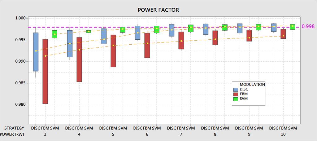
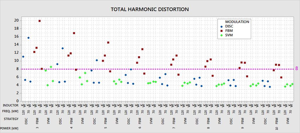
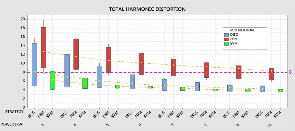
29 Power Factor & THD
30 Thank you 30 2/2/2018
Chapter 2 MODELING AND CONTROL OF PEBB BASED SYSTEMS
 Chapter 2 MODELING AND CONTROL OF PEBB BASED SYSTEMS 2.1 Introduction The PEBBs are fundamental building cells, integrating state-of-the-art techniques for large scale power electronics systems. Conventional
Direct Power Control With Space Vector Modulation And Fuzzy DC- Voltage Control- PWM rectifier
 Direct Power Control With Space Vector Modulation And Fuzzy DC Voltage Control PWM rectifier H.DENOUN, A.FEKIK, N.BENAMROUCHE. N.BENYAHIA, M.ZAOUIA, A. BADJI Electrical Engineering Advanced Technology
GaN in Practical Applications
 in Practical Applications 1 CCM Totem Pole PFC 2 PFC: applications and topology Typical AC/DC PSU 85-265 V AC 400V DC for industrial, medical, PFC LLC 12, 24, 48V DC telecomm and server applications. PFC
Simulation And Comparison Of Space Vector Pulse Width Modulation For Three Phase Voltage Source Inverter
 Simulation And Comparison Of Space Vector Pulse Width Modulation For Three Phase Voltage Source Inverter Associate Prof. S. Vasudevamurthy Department of Electrical and Electronics Dr. Ambedkar Institute
CHAPTER 5 POWER QUALITY IMPROVEMENT BY USING POWER ACTIVE FILTERS
 86 CHAPTER 5 POWER QUALITY IMPROVEMENT BY USING POWER ACTIVE FILTERS 5.1 POWER QUALITY IMPROVEMENT This chapter deals with the harmonic elimination in Power System by adopting various methods. Due to the
Designing a 99% Efficient Totem Pole PFC with GaN. Serkan Dusmez, Systems and applications engineer
 Designing a 99% Efficient Totem Pole PFC with GaN Serkan Dusmez, Systems and applications engineer 1 What will I get out of this session? Purpose: Why GaN Based Totem-pole PFC? Design guidelines for getting
Designing reliable and high density power solutions with GaN. Created by: Masoud Beheshti Presented by: Paul L Brohlin
 Designing reliable and high density power solutions with GaN Created by: Masoud Beheshti Presented by: Paul L Brohlin What will I get out of this presentation? Why GaN? Integration for System Performance
POWER- SWITCHING CONVERTERS Medium and High Power
 POWER- SWITCHING CONVERTERS Medium and High Power By Dorin O. Neacsu Taylor &. Francis Taylor & Francis Group Boca Raton London New York CRC is an imprint of the Taylor & Francis Group, an informa business
Digital Control IC for Interleaved PFCs
 Digital Control IC for Interleaved PFCs Rosario Attanasio Applications Manager STMicroelectronics Presentation Outline 2 PFC Basics Interleaved PFC Concept Analog Vs Digital Control The STNRGPF01 Digital
R. W. Erickson. Department of Electrical, Computer, and Energy Engineering University of Colorado, Boulder
 R. W. Erickson Department of Electrical, Computer, and Energy Engineering University of Colorado, Boulder 16.4. Power phasors in sinusoidal systems Apparent power is the product of the rms voltage and
Space Vector PWM and Model Predictive Control for Voltage Source Inverter Control
 Space Vector PWM and Model Predictive Control for Voltage Source Inverter Control Irtaza M. Syed, Kaamran Raahemifar Abstract In this paper, we present a comparative assessment of Space Vector Pulse Width
IBM Technology Symposium
 IBM Technology Symposium Impact of Input Voltage on Server PSU- Efficiency, Power Density and Cost Design. Build. Ship. Service. Sriram Chandrasekaran November 13, 2012 Presentation Outline Redundant Server
Chapter 2 Shunt Active Power Filter
 Chapter 2 Shunt Active Power Filter In the recent years of development the requirement of harmonic and reactive power has developed, causing power quality problems. Many power electronic converters are
CHAPTER 6 UNIT VECTOR GENERATION FOR DETECTING VOLTAGE ANGLE
 98 CHAPTER 6 UNIT VECTOR GENERATION FOR DETECTING VOLTAGE ANGLE 6.1 INTRODUCTION Process industries use wide range of variable speed motor drives, air conditioning plants, uninterrupted power supply systems
Control Of Shunt Active Filter Based On Instantaneous Power Theory
 B.Pragathi Department of Electrical and Electronics Shri Vishnu Engineering College for Women Bhimavaram, India Control Of Shunt Active Filter Based On Instantaneous Power Theory G.Bharathi Department
Designing High density Power Solutions with GaN Created by: Masoud Beheshti Presented by: Xaver Arbinger
 Designing High density Power Solutions with GaN Created by: Masoud Beheshti Presented by: Xaver Arbinger Topics Why GaN? Integration for Higher System Performance Application Examples Taking GaN beyond
IMPORTANCE OF VSC IN HVDC
 IMPORTANCE OF VSC IN HVDC Snigdha Sharma (Electrical Department, SIT, Meerut) ABSTRACT The demand of electrical energy has been increasing day by day. To meet these high demands, reliable and stable transmission
Power of GaN. Enabling designers to create smaller, more efficient and higher-performing AC/DC power supplies
 Power of GaN Enabling designers to create smaller, more efficient and higher-performing AC/DC power supplies Steve Tom Product Line Manager, GaN Products stom@ti.com Solving power and energy-management
VIENNA Rectifier & Beyond...
 VIENNA Rectifier & Beyond... Johann W. Kolar et al. Swiss Federal Institute of Technology (ETH) Zurich Power Electronic Systems Laboratory www.pes.ee.ethz.ch VIENNA Rectifier & Beyond... J. W. Kolar, L.
CHAPTER 3 COMBINED MULTIPULSE MULTILEVEL INVERTER BASED STATCOM
 CHAPTER 3 COMBINED MULTIPULSE MULTILEVEL INVERTER BASED STATCOM 3.1 INTRODUCTION Static synchronous compensator is a shunt connected reactive power compensation device that is capable of generating or
A New Single Switch Bridgeless SEPIC PFC Converter with Low Cost, Low THD and High PF
 A New Single Switch Bridgeless SEPIC PFC Converter with ow Cost, ow THD and High PF Yasemin Onal, Yilmaz Sozer The University of Bilecik Seyh Edebali, Department of Electrical and Electronic Engineering,
PC Krause and Associates, Inc.
 Common-mode challenges in high-frequency switching converters 14 NOV 2016 Nicholas Benavides, Ph.D. (Sr. Lead Engineer) 3000 Kent Ave., Suite C1-100 West Lafayette, IN 47906 (765) 464-8997 (Office) (765)
Boundary Mode Offline LED Driver Using MP4000. Application Note
 The Future of Analog IC Technology AN046 Boundary Mode Offline LED Driver Using MP4000 Boundary Mode Offline LED Driver Using MP4000 Application Note Prepared by Zheng Luo March 25, 2011 AN046 Rev. 1.0
CHAPTER-III MODELING AND IMPLEMENTATION OF PMBLDC MOTOR DRIVE
 CHAPTER-III MODELING AND IMPLEMENTATION OF PMBLDC MOTOR DRIVE 3.1 GENERAL The PMBLDC motors used in low power applications (up to 5kW) are fed from a single-phase AC source through a diode bridge rectifier
CHAPTER 3. SINGLE-STAGE PFC TOPOLOGY GENERALIZATION AND VARIATIONS
 CHAPTER 3. SINGLE-STAGE PFC TOPOLOG GENERALIATION AND VARIATIONS 3.1. INTRODUCTION The original DCM S 2 PFC topology offers a simple integration of the DCM boost rectifier and the PWM DC/DC converter.
ELEC387 Power electronics
 ELEC387 Power electronics Jonathan Goldwasser 1 Power electronics systems pp.3 15 Main task: process and control flow of electric energy by supplying voltage and current in a form that is optimally suited
Vector Control of Three-Phase Active Front End Rectifier
 IJIRST International Journal for Innovative Research in Science & Technology Volume 2 Issue 09 February 2016 ISSN (online): 2349-6010 Vector Control of Three-Phase Active Front End Rectifier Heema Shukla
Power Quality Improvement of Non-Linear Load by Using Instantaneous P-Q Theory
 Power Quality Improvement of Non-Linear Load by Using Instantaneous P-Q Theory 1 R.V.L. Narayana Divakar, 2 P.Kishore, 3 CH.Ravi Kumar, 4 V.Madhu Kishore, 5 V.Pradeep Kumar 1 Assistant Professor, 2,3,4,5
ABSTRACT. Introduction
 Simulation Of A 4-Switch,3-Phase Inverter Fed Induction Motor (IM) Drive System Prof. A.A.Apte AISSMS College of Engineering, Pune University/Pune, Maharashtra, India V.D.Malwade AISSMS College of Engineering,
Design and Implementation of a Three-Phase Boost Battery Charger with PFC using CompactRIO Control System
 Design and Implementation of a Three-Phase Boost Battery Charger with PFC using CompactRIO Control System Master of Science Thesis in Electric Power Engineering Daniel Castro Carmona Javier Fernández Mandiola
CHAPTER 2 GENERAL STUDY OF INTEGRATED SINGLE-STAGE POWER FACTOR CORRECTION CONVERTERS
 CHAPTER 2 GENERAL STUDY OF INTEGRATED SINGLE-STAGE POWER FACTOR CORRECTION CONVERTERS 2.1 Introduction Conventional diode rectifiers have rich input harmonic current and cannot meet the IEC PFC regulation,
IJSTE - International Journal of Science Technology & Engineering Volume 2 Issue 12 June 2016 ISSN (online): X
: X") IJSTE - International Journal of Science Technology & Engineering Volume 2 Issue 12 June 2016 ISSN (online): 2349-784X A Synchronous Reference Frame Theory-Space Vector Modulation (SRF SPVM) based Active
IJSTE - International Journal of Science Technology & Engineering Volume 2 Issue 12 June 2016 ISSN (online): 2349-784X A Synchronous Reference Frame Theory-Space Vector Modulation (SRF SPVM) based Active
Effective Algorithm for Reducing DC Link Neutral Point Voltage and Total Harmonic Distortion for Five Level Inverter
 Effective Algorithm for Reducing DC Link Neutral Point Voltage Total Harmonic Distortion for Five Level Inverter S. Sunisith 1, K. S. Mann 2, Janardhan Rao 3 sunisith@gmail.com, hodeee.gnit@gniindia.org,
SHUNT ACTIVE POWER FILTER
 75 CHAPTER 4 SHUNT ACTIVE POWER FILTER Abstract A synchronous logic based Phase angle control method pulse width modulation (PWM) algorithm is proposed for three phase Shunt Active Power Filter (SAPF)
Control of Grid Interactive Inverter Systems
 Control of Grid Interactive Inverter Systems Dr. M.Nanda Kumar Professor Dept. of Electrical Engg. Govt. Engineering College, Thrissur What is a Grid interactive inverter? DC Source Inverter AC Grid TCR
Electric Circuits II Three-Phase Circuits. Dr. Firas Obeidat
 Electric Circuits II Three-Phase Circuits Dr. Firas Obeidat 1 Table of Contents 1 Balanced Three-Phase Voltages 2 Balanced Wye-Wye Connection 3 Balanced Wye-Delta Connection 4 Balanced Delta-Delta Connection
EE152 Green Electronics
 EE152 Green Electronics Power Factor and Inverters 10/28/14 Prof. William Dally Computer Systems Laboratory Stanford University Lab 5 PV lab this week Course Logistics Solar day is on Thursday 10/30/14
INSTANTANEOUS POWER CONTROL OF D-STATCOM FOR ENHANCEMENT OF THE STEADY-STATE PERFORMANCE
 INSTANTANEOUS POWER CONTROL OF D-STATCOM FOR ENHANCEMENT OF THE STEADY-STATE PERFORMANCE Ms. K. Kamaladevi 1, N. Mohan Murali Krishna 2 1 Asst. Professor, Department of EEE, 2 PG Scholar, Department of
Tutorial 5 - Isolated DC-DC Converters and Inverters
 University of New South Wales School of Electrical Engineering and Telecommunications Tutorial 5 - Isolated DC-DC Converters and Inverters Flyback Converter N2 3 1. A dc-dc flyback converter has a turns
Demonstration. Agenda
 Demonstration Edward Lee 2009 Microchip Technology, Inc. 1 Agenda 1. Buck/Boost Board with Explorer 16 2. AC/DC Reference Design 3. Pure Sinewave Inverter Reference Design 4. Interleaved PFC Reference
Lecture 4 - Three-phase circuits, transformer and transient analysis of RLC circuits. Figure 4.1
 Lecture 4 - Three-phase circuits, transformer and transient analysis of RLC circuits Power supply to sizeable power converters are often from three-phase AC source. A balanced three-phase source consists
Improvements of LLC Resonant Converter
 Chapter 5 Improvements of LLC Resonant Converter From previous chapter, the characteristic and design of LLC resonant converter were discussed. In this chapter, two improvements for LLC resonant converter
A Modified Direct Power Control Strategy Allowing the Connection of Three-Phase Inverter to the Grid through LCL Filters
 A Modified Direct Power Control Strategy Allowing the Connection of ThreePhase Inverter to the Grid through C Filters. A. Serpa and J. W. Kolar Power Electronic Systems aboratory Swiss Federal Institute
Conventional Paper-II-2013
 1. All parts carry equal marks Conventional Paper-II-013 (a) (d) A 0V DC shunt motor takes 0A at full load running at 500 rpm. The armature resistance is 0.4Ω and shunt field resistance of 176Ω. The machine
R. W. Erickson. Department of Electrical, Computer, and Energy Engineering University of Colorado, Boulder
 R. W. Erickson Department of Electrical, Computer, and Energy Engineering University of Colorado, Boulder 6.3.5. Boost-derived isolated converters A wide variety of boost-derived isolated dc-dc converters
Power Quality Improvement using Shunt Passive Filter
 Power Quality Improvement using Shunt Passive Filter Assistant Professor, Department of Electrical Engineering Bhutta Group of Institutions, India Abstract: The electricity supply would, ideally, show
Chapter 33. Alternating Current Circuits
 Chapter 33 Alternating Current Circuits Alternating Current Circuits Electrical appliances in the house use alternating current (AC) circuits. If an AC source applies an alternating voltage to a series
Space Vector PWM Voltage Source Inverter Fed to Permanent Magnet Synchronous Motor
 International Journal of Engineering Research and Development e-issn: 2278-067X, p-issn: 2278-800X, www.ijerd.com Volume 12, Issue 6 (June 2016), PP.50-60 Space Vector PWM Voltage Source Inverter Fed to
Introduction to Rectifiers and their Performance Parameters
 Electrical Engineering Division Page 1 of 10 Rectification is the process of conversion of alternating input voltage to direct output voltage. Rectifier is a circuit that convert AC voltage to a DC voltage
PERFORMANCE EVALUATION OF THREE PHASE SCALAR CONTROLLED PWM RECTIFIER USING DIFFERENT CARRIER AND MODULATING SIGNAL
 Journal of Engineering Science and Technology Vol. 10, No. 4 (2015) 420-433 School of Engineering, Taylor s University PERFORMANCE EVALUATION OF THREE PHASE SCALAR CONTROLLED PWM RECTIFIER USING DIFFERENT
Dr.Arkan A.Hussein Power Electronics Fourth Class. Operation and Analysis of the Three Phase Fully Controlled Bridge Converter
 Operation and Analysis of the Three Phase Fully Controlled Bridge Converter ١ Instructional Objectives On completion the student will be able to Draw the circuit diagram and waveforms associated with a
2.4 Modeling and Analysis of Three Phase Four Leg Inverter
 2.4 Modeling and Analysis of Three Phase Four Leg Inverter The main feature of a three phase inverter, with an additional neutral leg, is its ability to deal with load unbalance in a standalone power supply
Gate drive card converts logic level turn on/off commands. Gate Drive Card for High Power Three Phase PWM Converters. Engineer R&D
 Gate Drive Card for High Power Three Phase PWM Converters 1 Anil Kumar Adapa Engineer R&D Medha Servo Drive Pvt. Ltd., India Email: anilkumaradapa@gmail.com Vinod John Department of Electrical Engineering
A Predictive Control Strategy for Power Factor Correction
 IOSR Journal of Electrical and Electronics Engineering (IOSR-JEEE) e-issn: 2278-1676,p-ISSN: 2320-3331, Volume 8, Issue 6 (Nov. - Dec. 2013), PP 07-13 A Predictive Control Strategy for Power Factor Correction
CHAPTER 6 CURRENT REGULATED PWM SCHEME BASED FOUR- SWITCH THREE-PHASE BRUSHLESS DC MOTOR DRIVE
 125 CHAPTER 6 CURRENT REGULATED PWM SCHEME BASED FOUR- SWITCH THREE-PHASE BRUSHLESS DC MOTOR DRIVE 6.1 INTRODUCTION Permanent magnet motors with trapezoidal back EMF and sinusoidal back EMF have several
v o v an i L v bn V d Load L v cn D 1 D 3 D 5 i a i b i c D 4 D 6 D 2 Lecture 7 - Uncontrolled Rectifier Circuits III
 Lecture 7 - Uncontrolled Rectifier Circuits III Three-phase bridge rectifier (p = 6) v o n v an v bn v cn i a i b i c D 1 D 3 D 5 D 4 D 6 D d i L R Load L Figure 7.1 Three-phase diode bridge rectifier
CHAPTER-IV EXPERIMENTAL AND SIMULATION PROGRAM
 49 CHAPTER-IV EXPERIMENTAL AND SIMULATION PROGRAM 4.0 INTRODUCTION This chapter covers in detail the experimental set up of proposed Z source Matrix (ZSMC) based UPFC and compares with a lab scale model
Simulation and Comparision of Back To Back System using Bidirectional Isolated DC-DC Converter with Active Energy Storage
 International Journal of Electrical Engineering. ISSN 0974-2158 Volume 5, Number 3 (2012), pp. 231-238 International Research Publication House http://www.irphouse.com Simulation and Comparision of Back
A Comparative Study between DPC and DPC-SVM Controllers Using dspace (DS1104)
") International Journal of Electrical and Computer Engineering (IJECE) Vol. 4, No. 3, June 2014, pp. 322 328 ISSN: 2088-8708 322 A Comparative Study between DPC and DPC-SVM Controllers Using dspace (DS1104)
International Journal of Electrical and Computer Engineering (IJECE) Vol. 4, No. 3, June 2014, pp. 322 328 ISSN: 2088-8708 322 A Comparative Study between DPC and DPC-SVM Controllers Using dspace (DS1104)
CHAPTER 2 CURRENT SOURCE INVERTER FOR IM CONTROL
 9 CHAPTER 2 CURRENT SOURCE INVERTER FOR IM CONTROL 2.1 INTRODUCTION AC drives are mainly classified into direct and indirect converter drives. In direct converters (cycloconverters), the AC power is fed
DIRECT TORQUE CONTROL OF THREE PHASE INDUCTION MOTOR BY USING FOUR SWITCH INVERTER
 DIRECT TORQUE CONTROL OF THREE PHASE INDUCTION MOTOR BY USING FOUR SWITCH INVERTER Mr. Aniket C. Daiv. TSSM's BSCOER, Narhe ABSTRACT Induction motor proved its importance, since its invention and has been
OVERVIEW OF SVC AND STATCOM FOR INSTANTANEOUS POWER CONTROL AND POWER FACTOR IMPROVEMENT
 OVERVIEW OF SVC AND STATCOM FOR INSTANTANEOUS POWER CONTROL AND POWER FACTOR IMPROVEMENT Harshkumar Sharma 1, Gajendra Patel 2 1 PG Scholar, Electrical Department, SPCE, Visnagar, Gujarat, India 2 Assistant
PSPWM Control Strategy and SRF Method of Cascaded H-Bridge MLI based DSTATCOM for Enhancement of Power Quality
 PSPWM Control Strategy and SRF Method of Cascaded H-Bridge MLI based DSTATCOM for Enhancement of Power Quality P.Padmavathi, M.L.Dwarakanath, N.Sharief, K.Jyothi Abstract This paper presents an investigation
Power Factor Correction Why and How?
 Power Factor Correction Why and How? Renesas Electronics America Inc. Renesas Technology & Solution Portfolio 2 Microcontroller and Microprocessor Line-up 2010 2013 32-bit 8/16-bit 1200 DMIPS, Superscalar
CHAPTER 2 A SERIES PARALLEL RESONANT CONVERTER WITH OPEN LOOP CONTROL
 14 CHAPTER 2 A SERIES PARALLEL RESONANT CONVERTER WITH OPEN LOOP CONTROL 2.1 INTRODUCTION Power electronics devices have many advantages over the traditional power devices in many aspects such as converting
Get Your GaN PhD in Less Than 60 Minutes!
 Get Your GaN PhD in Less Than 60 Minutes! 1 Detailed agenda Why is GaN Exciting GaN Fundamentals Cost and Reliability Totem Pole PFC Isolated LLC Motor Drive LiDAR Driving GaN Choosing a GaN Tools 4 Why
A Novel Concept in Integrating PFC and DC/DC Converters *
 A Novel Concept in Integrating PFC and DC/DC Converters * Pit-Leong Wong and Fred C. Lee Center for Power Electronics Systems The Bradley Department of Electrical and Computer Engineering Virginia Polytechnic
Dead-Time Compensation Method for Vector-Controlled VSI Drives Based on Qorivva Family
 Freescale Semiconductor Document Number: AN4863 Application Note Rev 0, June Dead-Time Compensation Method for Vector-Controlled VSI Drives Based on Qorivva Family by: Petr Konvicny 1 Introduction One
CHAPTER 6 THREE-LEVEL INVERTER WITH LC FILTER
 97 CHAPTER 6 THREE-LEVEL INVERTER WITH LC FILTER 6.1 INTRODUCTION Multi level inverters are proven to be an ideal technique for improving the voltage and current profile to closely match with the sinusoidal
A VARIABLE SPEED PFC CONVERTER FOR BRUSHLESS SRM DRIVE
 A VARIABLE SPEED PFC CONVERTER FOR BRUSHLESS SRM DRIVE Mrs. M. Rama Subbamma 1, Dr. V. Madhusudhan 2, Dr. K. S. R. Anjaneyulu 3 and Dr. P. Sujatha 4 1 Professor, Department of E.E.E, G.C.E.T, Y.S.R Kadapa,
5DESIGN PARAMETERS OF SHUNT ACTIVE FILTER FOR HARMONICS CURRENT MITIGATION
 5DESIGN PARAMETERS OF SHUNT ACTIE FILTER FOR HARMONICS CURRENT MITIGATION Page 59 A.H. Budhrani 1*, K.J. Bhayani 2, A.R. Pathak 3 1*, 2, 3 Department of Electrical Engineering,..P. Engineering College
Capacitor Voltage Balancing of Five Level Diode Clamped Converter based STATCOM
 Indonesian Journal of Electrical Engineering and Computer Science Vol. 2, No. 2, May 2016, pp. 259 ~ 267 DOI: 10.11591/ijeecs.v2.i2.pp259-267 259 Capacitor Voltage Balancing of Five Level Diode Clamped
Vienna Rectifier Fed BLDC Motor
 Vienna Rectifier Fed BLDC Motor Dr. P. Sweety Jose 1, R.Gowthamraj 2 1 Assistant Professor, 2 PG Scholar, Dept. of Electrical & Electronics Engg., PSG College of Technology, Coimbatore 1 psj.eee@psgtech.ac.in
Performance Comparison of a Three Phase AC to Three Phase AC Matrix Converter using Different Carrier based Switching Algorithms
 http:// ISSN: 78-0181 Vol. 6 Issue 05, May - 017 Performance Comparison of a Three Phase AC to Three Phase AC Matrix Converter using Different Carrier based Switching Algorithms Dr. Narayanaswamy P R Iyer
ABSTRACT I. INTRODUCTION
 International Journal of Scientific Research in Computer Science, Engineering and Information Technology 2017 IJSRCSEIT Volume 2 Issue 6 ISSN : 2456-3307 Design of Shunt Active Power Filter for Power Quality
A Three-Phase Buck Rectifier with High-Frequency Isolation by Single-Stage
 A Three-Phase Buck Rectifier with High-Frequency Isolation by Single-Stage D. S. Greff, R. da Silva, S. A. Mussa, A. Perin and I. Barbi Federal University of Santa Caratina Power Electronics Institute-INEP
Power Electronics (BEG335EC )
") 1 Power Electronics (BEG335EC ) 2 PURWANCHAL UNIVERSITY V SEMESTER FINAL EXAMINATION - 2003 The figures in margin indicate full marks. Attempt any FIVE questions. Q. [1] [a] A single phase full converter
1 Power Electronics (BEG335EC ) 2 PURWANCHAL UNIVERSITY V SEMESTER FINAL EXAMINATION - 2003 The figures in margin indicate full marks. Attempt any FIVE questions. Q. [1] [a] A single phase full converter
CHAPTER 1 INTRODUCTION
 CHAPTER 1 INTRODUCTION 1.1 Introduction Power semiconductor devices constitute the heart of the modern power electronics, and are being extensively used in power electronic converters in the form of a
Sensorless Vector Control and Implementation: Why and How
 Sensorless Vector Control and Implementation: Why and How Renesas Electronics America Inc. Renesas Technology & Solution Portfolio 2 Microcontroller and Microprocessor Line-up 2010 2013 32-bit 8/16-bit
Using the EVM: PFC Design Tips and Techniques
 PFC Design Tips and Techniques Features: Bare die attach with epoxy Gold wire bondable Integral precision resistors Reduced size and weight High temperature operation Solder ready surfaces for flip chips
IEEE TRANSACTIONS ON POWER ELECTRONICS, VOL. 27, NO. 11, NOVEMBER
 IEEE TRANSACTIONS ON POWER ELECTRONICS, VOL. 27, NO. 11, NOVEMBER 2012 4391 A Novel DC-Side Zero-Voltage Switching (ZVS) Three-Phase Boost PWM Rectifier Controlled by an Improved SVM Method Zhiyuan Ma,
Enhancement of Power Quality in Distribution System Using D-Statcom for Different Faults
 Enhancement of Power Quality in Distribution System Using D-Statcom for Different s Dr. B. Sure Kumar 1, B. Shravanya 2 1 Assistant Professor, CBIT, HYD 2 M.E (P.S & P.E), CBIT, HYD Abstract: The main
R. W. Erickson. Department of Electrical, Computer, and Energy Engineering University of Colorado, Boulder
 R. W. Erickson Department of Electrical, Computer, and Energy Engineering University of Colorado, Boulder 18.2.2 DCM flyback converter v ac i ac EMI filter i g v g Flyback converter n : 1 L D 1 i v C R
HARMONICS THE BASICS H A R M O N I C M I T I G A T I O N A N D D I S P L A C E M E N T P O W E R F A C T O R C O R R E C T I O N
 HARMONICS THE BASICS H A R M O N I C M I T I G A T I O N A N D D I S P L A C E M E N T P O W E R F A C T O R C O R R E C T I O N Harmonic Basics 3 rd Harmonic Fundamental 5 t1h Harmonic 7 th Harmonic Harmonic
1.5MHz, 2A Synchronous Step-Down Regulator
 1.5MHz, 2A Synchronous Step-Down Regulator General Description The is a high efficiency current mode synchronous buck PWM DC-DC regulator. The internal generated 0.6V precision feedback reference voltage
Core Technology Group Application Note 1 AN-1
 Measuring the Impedance of Inductors and Transformers. John F. Iannuzzi Introduction In many cases it is necessary to characterize the impedance of inductors and transformers. For instance, power supply
12V-65W WIDE-RANGE INPUT MAINS ADAPTER USING THE L6566B
 APPLICATION NOTE 12V-65W WIDE-RANGE INPUT MAINS ADAPTER USING THE L6566B Introduction This note describes the characteristics and the features of a 65 W reference board, wide-range input mains, AC-DC adapter
ANALYSIS OF EFFECTS OF VECTOR CONTROL ON TOTAL CURRENT HARMONIC DISTORTION OF ADJUSTABLE SPEED AC DRIVE
 ANALYSIS OF EFFECTS OF VECTOR CONTROL ON TOTAL CURRENT HARMONIC DISTORTION OF ADJUSTABLE SPEED AC DRIVE KARTIK TAMVADA Department of E.E.E, V.S.Lakshmi Engineering College for Women, Kakinada, Andhra Pradesh,
CHAPTER 4 MODIFIED H- BRIDGE MULTILEVEL INVERTER USING MPD-SPWM TECHNIQUE
 58 CHAPTER 4 MODIFIED H- BRIDGE MULTILEVEL INVERTER USING MPD-SPWM TECHNIQUE 4.1 INTRODUCTION Conventional voltage source inverter requires high switching frequency PWM technique to obtain a quality output
A NEW SINGLE STAGE THREE LEVEL ISOLATED PFC CONVERTER FOR LOW POWER APPLICATIONS
 A NEW SINGLE STAGE THREE LEVEL ISOLATED PFC CONVERTER FOR LOW POWER APPLICATIONS S.R.Venupriya 1, Nithyananthan.K 2, Ranjidharan.G 3, Santhosh.M 4,Sathiyadevan.A 5 1 Assistant professor, 2,3,4,5 Students
Design considerations for a Half- Bridge LLC resonant converter
 Design considerations for a Half- Bridge LLC resonant converter Why an HB LLC converter Agenda Configurations of the HB LLC converter and a resonant tank Operating states of the HB LLC HB LLC converter
Examples Paper 3B3/4 DC-AC Inverters, Resonant Converter Circuits. dc to ac converters
 Straightforward questions are marked! Tripos standard questions are marked * Examples Paper 3B3/4 DC-AC Inverters, Resonant Converter Circuits dc to ac converters! 1. A three-phase bridge converter using
11. Define the term pinch off voltage of MOSFET. (May/June 2012)
") Subject Code : EE6503 Branch : EEE Subject Name : Power Electronics Year/Sem. : III /V Unit - I PART-A 1. State the advantages of IGBT over MOSFET. (Nov/Dec 2008) 2. What is the function of snubber circuit?
Subject Code : EE6503 Branch : EEE Subject Name : Power Electronics Year/Sem. : III /V Unit - I PART-A 1. State the advantages of IGBT over MOSFET. (Nov/Dec 2008) 2. What is the function of snubber circuit?
Implementation of SRF based Multilevel Shunt Active Filter for Harmonic Control
 International Journal of Engineering Research and Development e-issn: 2278-067X, p-issn: 2278-800X, www.ijerd.com Volume 3, Issue 8 (September 2012), PP. 16-20 Implementation of SRF based Multilevel Shunt
Cree PV Inverter Tops 1kW/kg with All-SiC Design
 Cree PV Inverter Tops 1kW/kg with All-SiC Design Alejandro Esquivel September, 2014 Power Forum 2014 (Bologna) presentation sponsored by: Presentation Outline 1. Meeting an Industry Need a) 1kW/Kg b) No
ELE847 Advanced Electromechanical Systems Course Notes 2008 Edition
 Department of Electrical and Computer Engineering ELE847 Advanced Electromechanical Systems Course Notes 2008 Edition ELE847 Advanced Electromechanical Systems Table of Contents 1. Course Outline.... 1
AN IMPROVED ZERO-VOLTAGE-TRANSITION INTERLEAVED BOOST CONVERTER WITH HIGH POWER FACTOR
 AN IMPROVED ZERO-VOLTAGE-TRANSITION INTERLEAVED BOOST CONVERTER WITH HIGH POWER FACTOR Naci GENC 1, Ires ISKENDER 1 1 Gazi University, Faculty of Engineering and Architecture, Department of Electrical
CHAPTER 4 CONTROL ALGORITHM FOR PROPOSED H-BRIDGE MULTILEVEL INVERTER
 65 CHAPTER 4 CONTROL ALGORITHM FOR PROPOSED H-BRIDGE MULTILEVEL INVERTER 4.1 INTRODUCTION Many control strategies are available for the control of IMs. The Direct Torque Control (DTC) is one of the most
User Guide Introduction. IRMCS3043 System Overview/Guide. International Rectifier s imotion Team. Table of Contents
 User Guide 08092 IRMCS3043 System Overview/Guide By International Rectifier s imotion Team Table of Contents IRMCS3043 System Overview/Guide... 1 Introduction... 1 IRMCF343 Application Circuit... 2 Power
Low Switching Frequency Pulse Width Modulation For Induction Motor Drives
 Low Switching Frequency Pulse Width Modulation For Induction Motor Drives Avanish Tripathi, Prof. G. Narayanan Department of Electrical Engineering Indian Institute of Science, Bangalore - 560012 INDIA