Section3 Chapter 2: Operational Amplifiers
|
|
|
- Emery Cook
- 6 years ago
- Views:
Transcription
1 2012 Section3 Chapter 2: Operational Amplifiers Reference : Microelectronic circuits Sedra six edition 1/10/2012
2 Contents: 1- THE Ideal operational amplifier 2- Inverting configuration a. Closed loop gain b. Effect of finite open loop gain c. Input and output resistance d. Weighted summer 3- Non inverting configuration a. Closed loop gain b. Effect of finite open loop gain c. Input and output resistance d. Voltage follower 4- Assignment 1

3 1- The ideal operational amplifier(op-amp) Its main function is to amplify the voltage difference between node 1 and node 2 ( ) Where A is open loop gain In ideal op-amp the minimum number of terminals is 5 terminals Its characteristics : a. Very high input resistance b. Very low output resistance c. d. Very high open loop gain e., i.e. virtual short circuit, & Problem 2 The circuit of Fig. P2.2 uses an op amp that is ideal except for having a finite gain A. Measurements indicate = 4.0 V when = 2.0 V, What is the op-amp gain A? : 2
4 2- The inverting configuration A. Closed loop gain 7) Closed loop gain = = - Problem 8 Assuming Ideal op amp, Find the voltage gain of each of the circuits in Fig. P2.8 and input resistance = = - 100/10 = -10 v/v = 10 KΩ Problem 12 Given an ideal op amp, what are the values of the resistors to be used to design amplifiers with the closed-loop gains -2V/V In your designs, Use at least one 10 kω resistor and another equal or larger resistor. 3

5 = = -2 By assuming Problem 16 For the circuit in Fig P2.16, Assuming an ideal op amp, find the currents through all branches and the voltages at all nodes. Since the current supplied by the op amp is greater than the current drawn from the input signal source. Where does the additional current come from? ( ) The additional current comes from the output of op-amp B. Finite open loop gain (A ) 1) 2) 3) 4) 5) 6) ( ) 4
6 7) Problem 21 An op amp with an open-loop gain of 2000 V/V is used in the inverting configuration. If in this application the output voltage ranges from - 10V to + 10 V. what is the maximum voltage by which the "virtual ground node" departs from its ideal value? The voltage of the inverting input terminal will vary from to. Thus the virtual ground will depart from the ideal voltage of zero to maximum of C. Input and output resistance Input resistance = = Output resistance = ( ) D. Weighted summer ( ) 5
 If, is varied in the range 100Ω to 1 KΩ what is the corresponding change in and? (a) (b) (c) Remains the same If =100Ω = -2.01 V If =1K Ω -11.")
7 Problem 32 The circuit in Fig. P 2.32 utilizes an ideal op amp. (a) Find,,, and (b) If is not be lower than -13 V. find the maximum allowed value for (c) If, is varied in the range 100Ω to 1 KΩ what is the corresponding change in and? (a) (b) (c) Remains the same If =100Ω = V If =1K Ω V Problem 39 An Ideal op amp is connected in the weighted summer configuration of Fig The feedback resistor, = 10-kΩ, and six 10-kΩ resistors are connected to the Inverting input terminal of the op amp. Show by sketching the various circuit configurations, how this basic Circuit can be used to implement the follow function: = - ( + +, +5 ) 6
8 =10 KΩ =10 KΩ =5 KΩ but we have only 10 KΩ, so we can use two 10 KΩ in parallel 10 KΩ in parallel =2 KΩ but we have only 10 KΩ, so we can use five 3- Non inverting configuration A. Closed loop gain 7

9 7) Closed loop gain = = 1+ Problem 46 Figure P2.46 shows a circuit for an analog voltmeter of very high input resistance that uses an inexpensive moving-coil meter. The voltmeter measures the voltage applied between the op amp's positive-input terminal and ground. Assuming that the moving Coil produces full-scale deflection when the current passing through, It is 100 µa. find the value of R such that fullscale reading is obtained when V is 10 V. R = = =10 KΩ 8

10 Problem 51 The circuit shown to Fig P2.51 utilizes a 10 potentiometer to realize an adjustable-gain amplifier Derive an expression for the gain as a function of the potentiometer setting x Assume the op amp to be ideal. What is the range of gains obtained? Show how to add a fixed resistor so that the gain range can be 1 to 11 V/V what should the resistor value be? = 1+ = 1+ = When x=0 gain = When x=1 gain =1 The max value of gain =11 When x =0 = 1+ = 1+ = 11 R = 1 KΩ B. Finite open loop gain (A ) C. Input and output resistance Input resistance = = Output resistance = ( ) 9
11 D. Voltage follower (Buffer) = 10
12 Biomedical department 2 nd year 1 st term 2012 Electronics course Assignment no.3 Student name: Problem 10 You are provided with an ideal op amp and three 10 KΩ resistors. Using series and parallel resistor combinations, how many different Invertingamplifier circuit topologies are possible. What is the largest (non-infinite) available voltage gain? What is the smallest (nonzero) available gain? What are the Input resistances in these two cases? 11
13 Problem 20 (a) Design an Inverting amplifier with a closed loop gain of-100 V/V and an input resistance of 1 kω. (b) If the op amp is known to have an open-loop gain of 2000 V/V. what do you expect the closed-loop gain of your circuit to be? (C) Give the value of a resistor you can place in parallel (shunt) with to restore the closed-loop gain to its nominal value. Problem 27 a) Use Eq. (2.5) to show that a reduction A in the op amp gain A gives rise to a reduction IGI in the magnitude of the closed-loop gain with IGI and A related by b) If in a closed-loop amplifier with a nominal gain (i.e. ) of 100, A decreases by 50%. What is the minimum nominal A required to limit the percentage change in IGI to 0.5%? 12
 Find the resistances looking into node 1, ; node 2, ; node 3, and node 4, (b) Find the currents, and in terms of the input current (c) Find the")
14 Problem 31 The circuit in Fig. P2.31 can be considered to be an extension of the Circuit in Fig. 2.8 (a) Find the resistances looking into node 1, ; node 2, ; node 3, and node 4, (b) Find the currents, and in terms of the input current (c) Find the voltages at nodes 1, 2, 3 and 4 that is and in terms of (IR). 13
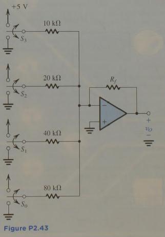
15 Problem 43 Figure P2.43 shows a circuit for a digital-to-analog converter (DAC). The circuit accepts a 4-bit input binary word where take the values of 0 or 1, and it provides an analog output voltage proportional to the value of the digital input. Each of the bits of the input word controls the correspondingly numbered switch. For Instance if is 0 then switch S, connects the 20-kΩ resistor to ground, while If is 1 then S connects the 20-kΩ resistor to the +5-V power supply. Show that is given by Where, is in kilo-ohms. Find the value of, so that ranges from 0 to - 12 volts. 14
16 15
17 Problem 56 A non-inverting op-amp circuit with nominal gain of 10 V/V uses an opamp with open-loop gain of 50 V/V and a lowest-value resistor of 10 kω, what closed-loop gain actually results? With what value resistor can which resistor be shunted to achieve the nominal gain? If in the manufacturing process an op amp of gain 100 V/V was used. What closed-loop gain would result in each case? 16
ELEC207 LINEAR INTEGRATED CIRCUITS
 Concept of VIRTUAL SHORT For feedback amplifiers constructed with op-amps, the two op-amp terminals will always be approximately equal (V + = V - ) This condition in op-amp feedback amplifiers is known
Chapter 2. Operational Amplifiers
 Chapter 2. Operational Amplifiers Tong In Oh 1 2.3 The Noninverting Configuration v I is applied directly to the positive input terminal of the op amp One terminal of is connected to ground Closed-loop
L02 Operational Amplifiers Applications 1
 L02 Operational Amplifiers Applications 1 Chapter 9 Ideal Operational Amplifiers and Op-Amp Circuits Donald A. Neamen (2009). Microelectronics: Circuit Analysis and Design, 4th Edition, Mc-Graw-Hill Prepared
+ power. V out. - power +12 V -12 V +12 V -12 V
 Question 1 Questions An operational amplifier is a particular type of differential amplifier. Most op-amps receive two input voltage signals and output one voltage signal: power 1 2 - power Here is a single
Homework Assignment 10
 Homework Assignment 10 Question The amplifier below has infinite input resistance, zero output resistance and an openloop gain. If, find the value of the feedback factor as well as so that the closed-loop
Example #6 1. An amplifier with a nominal gain
 1. An amplifier with a nominal gain A=1000 V/V exhibits a gain change of 10% as the operating temperature changes from 25 o C to 75 o C. If it is required to constrain the change to 0.1% by applying negative
Lesson number one. Operational Amplifier Basics
 What About Lesson number one Operational Amplifier Basics As well as resistors and capacitors, Operational Amplifiers, or Op-amps as they are more commonly called, are one of the basic building blocks
Data Conversion and Lab Lab 1 Fall Operational Amplifiers
 Operational Amplifiers Lab Report Objectives Materials See separate report form located on the course webpage. This form should be completed during the performance of this lab. 1) To construct and operate
C H A P T E R 02. Operational Amplifiers
 C H A P T E R 02 Operational Amplifiers The Op-amp Figure 2.1 Circuit symbol for the op amp. Figure 2.2 The op amp shown connected to dc power supplies. The Ideal Op-amp 1. Infinite input impedance 2.
Control System Circuits with Opamps
 Control System Circuits with Opamps 27.04.2009 Purpose To introduce opamps, transistors and their usage To apply a control system with analog circuit elements. Difference Amplifier Figure 1 Basic Difference
Operational Amplifiers
 1. Introduction Operational Amplifiers The student will be introduced to the application and analysis of operational amplifiers in this laboratory experiment. The student will apply circuit analysis techniques
EET 438a Automatic Control Systems Technology Laboratory 1 Analog Sensor Signal Conditioning
 EET 438a Automatic Control Systems Technology Laboratory 1 Analog Sensor Signal Conditioning Objectives: Use analog OP AMP circuits to scale the output of a sensor to signal levels commonly found in practical
Fundamentals of Electric Circuits Chapter 2. Copyright The McGraw-Hill Companies, Inc. Permission required for reproduction or display.
 Fundamentals of Electric Circuits Chapter 2 Copyright The McGraw-Hill Companies, Inc. Permission required for reproduction or display. Overview This chapter will introduce Ohm s law: a central concept
2. Meter Measurements and Loading Effects in Resistance Circuits
 2. Meter Measurements and Loading Effects in Resistance Circuits 2.1. Purpose 1. To measure and predict the affects of multimeter(s) on a circuit when measuring electrical quantities. 2. To make use of
Section 6 Chapter 2: Operational Amplifiers
 03 Section 6 Chapter : Operational Amplifiers eference : Microelectronic circuits Sedra sixth edition 4//03 4//03 Contents: - DC imperfections A. Offset voltage B. Solution of offset voltage C. Input bias
v 0 = A (v + - v - ) (1)
 (1)") UNIVERSITI TEKNOLOGI MALAYSIA KURSUS KEJURUTERAAN ELEKTRIK ELECTRONIC ENGINEERING LABORATORY 2 EXPERIMENT 2 : OPERATIONAL AMPLIFIER PRELIMINARY REPORT Name : Section : Group : Lecturer : Marks : 20 Attach
UNIVERSITI TEKNOLOGI MALAYSIA KURSUS KEJURUTERAAN ELEKTRIK ELECTRONIC ENGINEERING LABORATORY 2 EXPERIMENT 2 : OPERATIONAL AMPLIFIER PRELIMINARY REPORT Name : Section : Group : Lecturer : Marks : 20 Attach
ES250: Electrical Science. HW6: The Operational Amplifier
 ES250: Electrical Science HW6: The Operational Amplifier Introduction This chapter introduces the operational amplifier or op amp We will learn how to analyze and design circuits that contain op amps,
Laboratory 9. Required Components: Objectives. Optional Components: Operational Amplifier Circuits (modified from lab text by Alciatore)
") Laboratory 9 Operational Amplifier Circuits (modified from lab text by Alciatore) Required Components: 1x 741 op-amp 2x 1k resistors 4x 10k resistors 1x l00k resistor 1x 0.1F capacitor Optional Components:
Laboratory 9 Operational Amplifier Circuits (modified from lab text by Alciatore) Required Components: 1x 741 op-amp 2x 1k resistors 4x 10k resistors 1x l00k resistor 1x 0.1F capacitor Optional Components:
Operational Amplifiers (Op Amps)
") Operational Amplifiers (Op Amps) Introduction * An operational amplifier is modeled as a voltage controlled voltage source. * An operational amplifier has a very high input impedance and a very high gain.
Operational Amplifiers (Op Amps) Introduction * An operational amplifier is modeled as a voltage controlled voltage source. * An operational amplifier has a very high input impedance and a very high gain.
To configure op-amp in inverting and non-inverting amplifier mode and measure their gain.
 AIM: SUBJECT: ANALOG ELECTRONICS (2392) EXPERIMENT NO. 5 DATE : TITLE: TO CONFIGURE OP-AMP IN INVERTING AND NON- INVERTING AMPLIFIER MODE AND MEASURE THEIR GAIN. DOC. CODE : DIET/EE/3 rd SEM REV. NO. :./JUNE-25
An electronic unit that behaves like a voltagecontrolled
 1 An electronic unit that behaves like a voltagecontrolled voltage source. An active circuit element that amplifies, sums, subtracts, multiply, divide, differentiate or integrates a signal 2 A typical
Analog I/O. ECE 153B Sensor & Peripheral Interface Design Winter 2016
 Analog I/O ECE 153B Sensor & Peripheral Interface Design Introduction Anytime we need to monitor or control analog signals with a digital system, we require analogto-digital (ADC) and digital-to-analog
Unit 6 Operational Amplifiers Chapter 5 (Sedra and Smith)
") Unit 6 Operational Amplifiers Chapter 5 (Sedra and Smith) Prepared by: S V UMA, Associate Professor, Department of ECE, RNSIT, Bangalore Reference: Microelectronic Circuits Adel Sedra and K C Smith 1 Objectives
Unit 6 Operational Amplifiers Chapter 5 (Sedra and Smith) Prepared by: S V UMA, Associate Professor, Department of ECE, RNSIT, Bangalore Reference: Microelectronic Circuits Adel Sedra and K C Smith 1 Objectives
P a g e 1. Introduction
 P a g e 1 Introduction 1. Signals in digital form are more convenient than analog form for processing and control operation. 2. Real world signals originated from temperature, pressure, flow rate, force
using dc inputs. You will verify circuit operation with a multimeter.
 Op Amp Fundamentals using dc inputs. You will verify circuit operation with a multimeter. FACET by Lab-Volt 77 Op Amp Fundamentals O circuit common. a. inverts the input voltage polarity. b. does not invert
Laboratory Exercise - Seven
 Basic D.C. AVIM 121 Lab 7 Page 1 of 9 rev. 08.09 Laboratory Exercise - Seven Objectives Determine milliammeter equivalent resistance. Calculate and apply meter shunts and multipliers. Determine voltmeter
Precision Rectifier Circuits
 Precision Rectifier Circuits Rectifier circuits are used in the design of power supply circuits. In such applications, the voltage being rectified are usually much greater than the diode voltage drop,
Operational Amplifiers
 Operational Amplifiers Jim Emery 4/7/2011 Contents 1 Operational Amplifiers 1 11 The Inverting Amplifier 3 12 The Slew rate 5 13 The Noninverting Amplifier 5 14 The Voltage Follower 6 15 The Differentiating
Operational Amplifier BME 360 Lecture Notes Ying Sun
 Operational Amplifier BME 360 Lecture Notes Ying Sun Characteristics of Op-Amp An operational amplifier (op-amp) is an analog integrated circuit that consists of several stages of transistor amplification
ECE3040 Assignment9. 1. The figures show inverting amplifier circuits.
 ECE3040 Assignment9 1. The figures show inverting amplifier circuits. (a) For the circuit of Fig. (a), specify R 1, R F,andR O for a voltage gain of 50, an input resistance of 2kΩ, and an output resistance
Half-wave Rectifier AC Meters
 Note-4 1 Half-wave Rectifier AC Meters Disadvantages: 1. In negative half-cycle, reverse current flows through the circuit reduces average value of current meter reads lower than actual. 2. High peak inverse
Operational amplifiers
 Operational amplifiers Bởi: Sy Hien Dinh INTRODUCTION Having learned the basic laws and theorems for circuit analysis, we are now ready to study an active circuit element of paramount importance: the operational
Department of Mechanical Engineering
 Department of Mechanical Engineering 2.010 CONTROL SYSTEMS PRINCIPLES Introduction to the Operational Amplifier The integrated-circuit operational-amplifier is the fundamental building block for many electronic
Real Analog Chapter 2: Circuit Reduction. 2 Introduction and Chapter Objectives. After Completing this Chapter, You Should be Able to:
 1300 Henley Court Pullman, WA 99163 509.334.6306 www.store. digilent.com 2 Introduction and Chapter Objectives In Chapter 1, we presented Kirchhoff's laws (which govern the interaction between circuit
Chapter 9: Operational Amplifiers
 Chapter 9: Operational Amplifiers The Operational Amplifier (or op-amp) is the ideal, simple amplifier. It is an integrated circuit (IC). An IC contains many discrete components (resistors, capacitors,
Sensor Interfacing and Operational Amplifiers Lab 3
 Name Lab Day Lab Time Sensor Interfacing and Operational Amplifiers Lab 3 Introduction: In this lab you will design and build a circuit that will convert the temperature indicated by a thermistor s resistance
Chapter 9: Operational Amplifiers
 Chapter 9: Operational Amplifiers The Operational Amplifier (or op-amp) is the ideal, simple amplifier. It is an integrated circuit (IC). An IC contains many discrete components (resistors, capacitors,
Homework Assignment 13
 Question 1 Short Takes 2 points each. Homework Assignment 13 1. Classify the type of feedback uses in the circuit below (i.e., shunt-shunt, series-shunt, ) 2. True or false: an engineer uses series-shunt
Chapter 2. Operational Amplifiers
 Chapter 2. Operational Amplifiers Tong In Oh 1 Objective Terminal characteristics of the ideal op amp How to analyze op amp circuits How to use op amps to design amplifiers How to design more sophisticated
Basic Operational Amplifier Circuits
 Basic Operational Amplifier Circuits Comparators A comparator is a specialized nonlinear op-amp circuit that compares two input voltages and produces an output state that indicates which one is greater.
ENE/EIE 211 : Electronic Devices and Circuit Design II Lecture 1: Introduction
 ENE/EIE 211 : Electronic Devices and Circuit Design II Lecture 1: Introduction 1/14/2018 1 Course Name: ENE/EIE 211 Electronic Devices and Circuit Design II Credits: 3 Prerequisite: ENE/EIE 210 Electronic
Operational Amplifiers
 CHAPTER 5 Operational Amplifiers Operational amplifiers (or Op Amp) is an active circuit element that can perform mathematical operations between signals (e.g., amplify, sum, subtract, multiply, divide,
Laboratory 8 Operational Amplifiers and Analog Computers
 Laboratory 8 Operational Amplifiers and Analog Computers Introduction Laboratory 8 page 1 of 6 Parts List LM324 dual op amp Various resistors and caps Pushbutton switch (SPST, NO) In this lab, you will
Lab 6 Prelab Grading Sheet
 Lab 6 Prelab Grading Sheet NAME: Read through the Background section of this lab and print the prelab and in-lab grading sheets. Then complete the steps below and fill in the Prelab 6 Grading Sheet. You
Introduction to Operational Amplifiers
 P. R. Nelson ECE 322 Fall 2012 p. 1/50 Introduction to Operational Amplifiers Phyllis R. Nelson prnelson@csupomona.edu Professor, Department of Electrical and Computer Engineering California State Polytechnic
EE 201 Lab 1. Meters, DC sources, and DC circuits with resistors
 Meters, DC sources, and DC circuits with resistors 0. Prior to lab Read through the lab and do as many of the calculations as possible. Then, learn how to determine resistance values using the color codes.
EECE251 Circuit Analysis I Set 5: Operational Amplifiers
 EECE251 Circuit Analysis I Set 5: Operational Amplifiers Shahriar Mirabbasi Department of Electrical and Computer Engineering University of British Columbia shahriar@ece.ubc.ca 1 Amplifiers There are various
Homework Assignment True or false. For both the inverting and noninverting op-amp configurations, V OS results in
 Question 1 (Short Takes), 2 points each. Homework Assignment 02 1. An op-amp has input bias current I B = 1 μa. Make an estimate for the input offset current I OS. Answer. I OS is normally an order of
Homework Assignment 03
 Homework Assignment 03 Question 1 (Short Takes), 2 points each unless otherwise noted. 1. Two 0.68 μf capacitors are connected in series across a 10 khz sine wave signal source. The total capacitive reactance
Chapter 4 CONVERTING VOLTAGE AND CURRENT Name: Date: Chapter 4 AN INTRODUCTION TO THE EXPERIMENTS
 Chapter 4 AN INTRODUCTION TO THE EXPERIMENTS The following experiments are designed to demonstrate the use of the op-amp in forming current sources, voltage-to-current converters, and current-to-voltage
inverting V CC v O -V EE non-inverting
 Chapter 4 Operational Amplifiers 4.1 Introduction The operational amplifier (opamp for short) is perhaps the most important building block for the design of analog circuits. Combined with simple negative
University of Portland EE 271 Electrical Circuits Laboratory. Experiment: Digital-to-Analog Converter
 University of Portland EE 271 Electrical Circuits Laboratory Experiment: Digital-to-Analog Converter I. Objective The objective of this experiment is to build and test a circuit that can convert a binary
Operational Amplifiers
 Operational Amplifiers Table of contents 1. Design 1.1. The Differential Amplifier 1.2. Level Shifter 1.3. Power Amplifier 2. Characteristics 3. The Opamp without NFB 4. Linear Amplifiers 4.1. The Non-Inverting
Designing Information Devices and Systems I Discussion 10A
 Last Updated: 2019-04-09 07:42 1 EECS 16A Spring 2019 Designing Information Devices and Systems I Discussion 10A For Reference: Circuits Cookbook, Abridged Voltage Divider Voltage Summer Unity Gain Buffer
PH213 Chapter 26 solutions
 PH213 Chapter 26 solutions 26.6. IDENTIFY: The potential drop is the same across the resistors in parallel, and the current into the parallel combination is the same as the current through the 45.0-Ω resistor.
IFB270 Advanced Electronic Circuits
 IFB270 Advanced Electronic Circuits Chapter 13: Basic op-amp circuits Prof. Manar Mohaisen Department of EEC Engineering Introduction Review of the Precedent Lecture Op-amp operation modes and parameters
ENGINEERING. Unit 4 Principles of electrical and electronic engineering Suite. Cambridge TECHNICALS LEVEL 3
 2016 Suite Cambridge TECHNICALS LEVEL 3 ENGINEERING Unit 4 Principles of electrical and electronic engineering D/506/7269 Guided learning hours: 60 Version 3 October 2017 - black lines mark updates ocr.org.uk/engineering
VCC_BAR. Grounds. Power, either postive or negative REVIEW OF SYMBOLS
 LECTUE 4. OPEATIONAL AMPLIFIES EIEW OF SYMBOLS CC_BA Power, either postive or negative Grounds. Operational amplifiers (op-amps) are active devices. This means you must connect them to a power supply in
Lab Exercise # 9 Operational Amplifier Circuits
 Objectives: THEORY Lab Exercise # 9 Operational Amplifier Circuits 1. To understand how to use multiple power supplies in a circuit. 2. To understand the distinction between signals and power. 3. To understand
Basic electronics Prof. T.S. Natarajan Department of Physics Indian Institute of Technology, Madras Lecture- 24
 Basic electronics Prof. T.S. Natarajan Department of Physics Indian Institute of Technology, Madras Lecture- 24 Mathematical operations (Summing Amplifier, The Averager, D/A Converter..) Hello everybody!
Section 4: Operational Amplifiers
 Section 4: Operational Amplifiers Op Amps Integrated circuits Simpler to understand than transistors Get back to linear systems, but now with gain Come in various forms Comparators Full Op Amps Differential
CK-12 Physics Concepts - Intermediate Answer Key
 Chapter 19: Electrical Circuits 19.1 Series Circuits CK-12 Physics Concepts - Intermediate Answer Key 1. There are three 20.0 Ohm resistors connected in series across a 120 V generator. a. What is the
Infrared Communications Lab
 Infrared Communications Lab This lab assignment assumes that the student knows about: Ohm s Law oltage, Current and Resistance Operational Amplifiers (See Appendix I) The first part of the lab is to develop
Solution: Based on the slope of q(t): 20 A for 0 t 1 s dt = 0 for 3 t 4 s. 20 A for 4 t 5 s 0 for t 5 s 20 C. t (s) 20 C. i (A) Fig. P1.
: 20 A for 0 t 1 s dt = 0 for 3 t 4 s. 20 A for 4 t 5 s 0 for t 5 s 20 C. t (s) 20 C. i (A) Fig. P1.") Problem 1.24 The plot in Fig. P1.24 displays the cumulative charge q(t) that has entered a certain device up to time t. Sketch a plot of the corresponding current i(t). q 20 C 0 1 2 3 4 5 t (s) 20 C Figure
Problem 1.24 The plot in Fig. P1.24 displays the cumulative charge q(t) that has entered a certain device up to time t. Sketch a plot of the corresponding current i(t). q 20 C 0 1 2 3 4 5 t (s) 20 C Figure
EXPERIMENT 3 Circuit Construction and Operational Amplifier Circuits
 ELEC 2010 Lab Manual Experiment 3 PRE-LAB Page 1 of 8 EXPERIMENT 3 Circuit Construction and Operational Amplifier Circuits Introduction In this experiment you will learn how to build your own circuits
Operational Amplifiers
 Fundamentals of op-amp Operation modes Golden rules of op-amp Op-amp circuits Inverting & non-inverting amplifier Unity follower, integrator & differentiator Introduction An operational amplifier, or op-amp,
University of Pittsburgh
 University of Pittsburgh Experiment #1 Lab Report Frequency Response of Operational Amplifiers Submission Date: 05/29/2018 Instructors: Dr. Ahmed Dallal Shangqian Gao Submitted By: Nick Haver & Alex Williams
UNIT III Data Acquisition & Microcontroller System. Mr. Manoj Rajale
 UNIT III Data Acquisition & Microcontroller System Mr. Manoj Rajale Syllabus Interfacing of Sensors / Actuators to DAQ system, Bit width, Sampling theorem, Sampling Frequency, Aliasing, Sample and hold
Emitter Coupled Differential Amplifier
 Emitter Coupled Differential Amplifier Returning to the transistor, a very common and useful circuit is the differential amplifier. It's basic circuit is: Vcc Q1 Q2 Re Vee To see how this circuit works,
Objective: To study and verify the functionality of a) PN junction diode in forward bias. Sl.No. Name Quantity Name Quantity 1 Diode
 PN junction diode in forward bias. Sl.No. Name Quantity Name Quantity 1 Diode") Experiment No: 1 Diode Characteristics Objective: To study and verify the functionality of a) PN junction diode in forward bias Components/ Equipments Required: b) Point-Contact diode in reverse bias Components
Experiment No: 1 Diode Characteristics Objective: To study and verify the functionality of a) PN junction diode in forward bias Components/ Equipments Required: b) Point-Contact diode in reverse bias Components
ECE 363 FINAL (F16) 6 problems for 100 pts Problem #1: Fuel Pump Controller (18 pts)
 6 problems for 100 pts Problem #1: Fuel Pump Controller (18 pts)") ECE 363 FINAL (F16) NAME: 6 problems for 100 pts Problem #1: Fuel Pump Controller (18 pts) You are asked to design a high-side switch for a remotely operated fuel pump. You decide to use the IRF9520 power
ECE 363 FINAL (F16) NAME: 6 problems for 100 pts Problem #1: Fuel Pump Controller (18 pts) You are asked to design a high-side switch for a remotely operated fuel pump. You decide to use the IRF9520 power
EXAM Amplifiers and Instrumentation (EE1C31)
") DELFT UNIVERSITY OF TECHNOLOGY Faculty of Electrical Engineering, Mathematics and Computer Science EXAM Amplifiers and Instrumentation (EE1C31) April 18, 2017, 9.00-12.00 hr This exam consists of four
DELFT UNIVERSITY OF TECHNOLOGY Faculty of Electrical Engineering, Mathematics and Computer Science EXAM Amplifiers and Instrumentation (EE1C31) April 18, 2017, 9.00-12.00 hr This exam consists of four
Operational Amplifiers
 Basic Electronics Syllabus: Introduction to : Ideal OPAMP, Inverting and Non Inverting OPAMP circuits, OPAMP applications: voltage follower, addition, subtraction, integration, differentiation; Numerical
EE 210: CIRCUITS AND DEVICES
 EE 210: CIRCUITS AND DEVICES OPERATIONAL AMPLIFIERS PART II This is the second of two laboratory sessions that provide an introduction to the op amp. In this session you will study three amplifiers designs:
2. The. op-amp in and 10K. (a) 0 Ω. (c) 0.2% (d) (a) 0.02K. (b) 4. The. 5 V, then. 0V (virtual. (a) (c) Fall V. (d) V.
 0 Ω. (c) 0.2% (d) (a) 0.02K. (b) 4. The. 5 V, then. 0V (virtual. (a) (c) Fall V. (d) V.") Homework Assignment 04 Question 1 (2 points each unless noted otherwise) 1. A 9-V dc power supply generates 10 W in a resistor. What peak-to-peak amplitude should an ac source have to generate the same
Homework Assignment 04 Question 1 (2 points each unless noted otherwise) 1. A 9-V dc power supply generates 10 W in a resistor. What peak-to-peak amplitude should an ac source have to generate the same
Discrete Op-Amp Kit MitchElectronics 2019
 Discrete Op-Amp Kit MitchElectronics 2019 www.mitchelectronics.co.uk CONTENTS Introduction 3 Schematic 4 How It Works 5 Materials 9 Construction 10 Important Information 11 Page 2 INTRODUCTION Even if
Exercise 2: Temperature Measurement
 Exercise 2: Temperature Measurement EXERCISE OBJECTIVE When you have completed this exercise, you will be able to explain and demonstrate the use of an RTD in a temperature measurement application by using
EEE 2101 Circuit Theory I - Laboratory 1 Kirchoff s Laws, Series-Parallel Circuits
 ame & Surname: D: Date: EEE 20 Circuit Theory - Laboratory Kirchoff s Laws, Series-Parallel Circuits List of topics for this laboratory: Ohm s Law Kirchoff s Current Law(KCL) Kirchoff s Voltage Law(KVL)
Homework Assignment 01
 Homework Assignment 01 In this homework set students review some basic circuit analysis techniques, as well as review how to analyze ideal op-amp circuits. Numerical answers must be supplied using engineering
Laboratory 6. Lab 6. Operational Amplifier Circuits. Required Components: op amp 2 1k resistor 4 10k resistors 1 100k resistor 1 0.
 Laboratory 6 Operational Amplifier Circuits Required Components: 1 741 op amp 2 1k resistor 4 10k resistors 1 100k resistor 1 0.1 F capacitor 6.1 Objectives The operational amplifier is one of the most
Basic Information of Operational Amplifiers
 EC1254 Linear Integrated Circuits Unit I: Part - II Basic Information of Operational Amplifiers Mr. V. VAITHIANATHAN, M.Tech (PhD) Assistant Professor, ECE Department Objectives of this presentation To
Circuit produces an amplified negative version of v IN = R R R
 Inerting Amplifier Circuit produces an amplified negatie ersion of i = i, = 2 0 = 2 OUT OUT = 2 Example: Calculate OUT / and I for = 0.5V Solution: A V OUT 2 = = = 0 kω = 0 kω i 05. V = = = kω 05. ma
UNIVERSITI MALAYSIA PERLIS
 UNIVERSITI MALAYSIA PERLIS ANALOG ELECTRONICS II EMT 212 2009/2010 EXPERIMENT # 3 OP-AMP (OSCILLATORS) 1 1. OBJECTIVE: 1.1 To demonstrate the Wien bridge oscillator 1.2 To demonstrate the RC phase-shift
QUESTION BANK for Analog Electronics 4EC111 *
 OpenStax-CNX module: m54983 1 QUESTION BANK for Analog Electronics 4EC111 * Bijay_Kumar Sharma This work is produced by OpenStax-CNX and licensed under the Creative Commons Attribution License 4.0 Abstract
BANGLADESH UNIVERSITY OF ENGINEERING & TECHNOLOGY
 BANGLADESH UNIVERSITY OF ENGINEERING & TECHNOLOGY Electronics Circuits II Laboratory (EEE 208) Simulation Experiment No. 02 Study of the Characteristics and Application of Operational Amplifier (Part B)
Electrical Circuits I (ENGR 2405) Chapter 2 Ohm s Law, KCL, KVL, Resistors in Series/Parallel
 Chapter 2 Ohm s Law, KCL, KVL, Resistors in Series/Parallel") Electrical Circuits I (ENG 2405) Chapter 2 Ohm s Law, KCL, KVL, esistors in Series/Parallel esistivity Materials tend to resist the flow of electricity through them. This property is called resistance
Electrical Circuits I (ENG 2405) Chapter 2 Ohm s Law, KCL, KVL, esistors in Series/Parallel esistivity Materials tend to resist the flow of electricity through them. This property is called resistance
EXPERIMENT 2.2 NON-LINEAR OP-AMP CIRCUITS
 2.16 EXPERIMENT 2.2 NONLINEAR OPAMP CIRCUITS 2.2.1 OBJECTIVE a. To study the operation of 741 opamp as comparator. b. To study the operation of active diode circuits (precisions circuits) using opamps,
Lab 5 Kirchhoff s Laws and Superposition
 Lab 5 Kirchhoff s Laws and Superposition In this lab, Kirchhoff s laws will be investigated using a more complex circuit than in the previous labs. Two voltage sources and seven resistors are included
Chapter 3 Electronic Circuit for MWCNT Ethylene Sensor
 Chapter Electronic Circuit for MWCNT Ethylene Sensor This chapter deals with design and prototype development of electronic circuits required for MWCNT ethylene sensor application. The customized potentiostat
EE 368 Electronics Lab. Experiment 10 Operational Amplifier Applications (2)
") EE 368 Electronics Lab Experiment 10 Operational Amplifier Applications (2) 1 Experiment 10 Operational Amplifier Applications (2) Objectives To gain experience with Operational Amplifier (Op-Amp). To
EE 368 Electronics Lab Experiment 10 Operational Amplifier Applications (2) 1 Experiment 10 Operational Amplifier Applications (2) Objectives To gain experience with Operational Amplifier (Op-Amp). To
University of Pittsburgh
 University of Pittsburgh Experiment #7 Lab Report Analog-Digital Applications Submission Date: 08/01/2018 Instructors: Dr. Ahmed Dallal Shangqian Gao Submitted By: Nick Haver & Alex Williams Station #2
Electronic Instrument Disadvantage of moving coil meter Low input impedance High loading error for low-voltage range voltmeter
 EIE 240 Electrical and Electronic Measurement Class 6, February 20, 2015 1 Electronic Instrument Disadvantage of moving coil meter Low input impedance High loading error for low-voltage range voltmeter
Isolated Industrial Current Loop Using the IL300 Linear
 VISHAY SEMICONDUCTORS www.vishay.com Optocouplers and Solid-State Relays Application Note Isolated Industrial Current Loop Using the IL Linear INTRODUCTION Programmable logic controllers (PLC) were once
Unit 8 Combination Circuits
 Unit 8 Combination Circuits Objectives: Define a combination circuit. List the rules for parallel circuits. List the rules for series circuits. Solve for combination circuit values. Characteristics There
Exp. 1 USE OF BASIC ELECTRONIC MEASURING INSTRUMENTS, PART I
 Exp. 1 USE OF BASIC ELECTRONIC MEASURING INSTRUMENTS, PART I PURPOSE: To become familiar with some of the instruments used in this and subsequent labs. To develop proper laboratory procedures relative
Digital to Analog Converters (DAC) 15 March 2006 Doug Hinckley Lee Huynh Dooroo Kim
 15 March 2006 Doug Hinckley Lee Huynh Dooroo Kim") Digital to Analog Converters (DAC) 5 March 006 Doug Hinckley Lee Huynh Dooroo Kim What is a DAC? A digital to analog converter (DAC) converts a digital signal to an analog voltage or current output. 000
Digital to Analog Converters (DAC) 5 March 006 Doug Hinckley Lee Huynh Dooroo Kim What is a DAC? A digital to analog converter (DAC) converts a digital signal to an analog voltage or current output. 000
Techniques for Passive Circuit Analysis for. State Space Differential Equations
 Techniques for Passive Circuit Analysis for chp4 1 State Space Differential Equations 1. Draw circuit schematic and label components (e.g., R 1, R 2, C 1, L 1 ) 2. Assign voltage at each node (e.g., e
Fig [5]
![Fig [5]](/thumbs/82/85456687.jpg "Fig [5]") 1 (a) Fig. 4.1 shows the I-V characteristic of a light-emitting diode (LED). 40 I / 10 3 A 30 20 10 0 1.0 1.5 2.0 V / V Fig. 4.1 (i) In Describe the significant features of the graph in terms of current,
1 (a) Fig. 4.1 shows the I-V characteristic of a light-emitting diode (LED). 40 I / 10 3 A 30 20 10 0 1.0 1.5 2.0 V / V Fig. 4.1 (i) In Describe the significant features of the graph in terms of current,
Kirchhoff s laws. Objectives. Assessment. Assessment. Assessment. Assessment 5/27/14. Apply Kirchhoff s first and second laws.
 Kirchhoff s laws Objectives Apply Kirchhoff s first and second laws. Calculate the current and voltage for resistor circuits connected in parallel. Calculate the current and voltage for resistor circuits
DARSHAN INSTITUTE OF ENGINEERING & TECHNOLOGY
 BASIC ELECTRONICS (2006) Assignment:-: Circuit Concept. Explain in brief about Lumped circuit elements called resistor and capacitor. 2. How does a voltmeter differ from an ammeter? 3. State kirchhoff's