Control of DC Motors by Choppers. Dr. D G Padhan PSD 1
|
|
|
- Rudolph Gallagher
- 6 years ago
- Views:
Transcription
1 Control of DC Motors by Choppers Dr. D G Padhan PSD 1
2 DC Chopper a static power electronic device that converts fixed dc input voltage to a variable dc output voltage considered as dc equivalent of an ac transformer since they behave in an identical manner used all over the world for rapid transit systems used in trolley cars, marine hoist, forklift trucks and mine haulers offer smooth control, high efficiency, faster response and regeneration facility The power semiconductor devices used for a chopper circuit can be force commutated thyristor, power BJT, MOSFET and IGBT Dr. D G Padhan PSD 2
3 GTO based chopper are also used These devices are generally represented by a switch. When the switch is off, no current can flow. Current flows through the load when switch is on. The power semiconductor devices have on-state voltage drop of 0.5V to 2.5V across them. For the sake of simplicity, this voltage drop across these devices is generally neglected Dr. D G Padhan PSD 3
4 PRINCIPLE OF CHOPPER OPERATION A chopper is a high speed on" or off semiconductor switch It connects source to load and disconnect the load from source at a fast speed. In this manner, a chopped load voltage is obtained from a dc supply of constant magnitude Dr. D G Padhan PSD 4
5 Dr. D G Padhan PSD 5
6 During the period T on, chopper is on and load voltage is equal to source voltage Vs. During the period T off, chopper is off, load voltage is zero. In this manner, a chopped dc voltage is produced at the load terminals Dr. D G Padhan PSD 6
7 Dr. D G Padhan PSD 7
8 CONTROL STRATEGIES The average value of output voltage Vo can be controlled through duty cycle by opening and closing the semiconductor switch periodically. The various control strategies for varying duty cycle are as following: 1. Time ratio Control (TRC) 2. Current-Limit Control. Dr. D G Padhan PSD 8
9 Time ratio Control (TRC) Time ratio Ton/T(duty ratio) is varied. 1. CONSTANT FREQUENCY SYSTEM on-time is varied but chopping frequency f is kept constant. Variation of Ton means adjustment of pulse width, as such this scheme is also called pulse-width-modulation scheme. 2. VARIABLE FREQUENCY SYSTEM the chopping frequency f is varied and either (i) on-time Ton is kept constant or (ii) off-time Toff is kept constant. This method of controlling duty ratio is also called Frequency-modulation scheme. Dr. D G Padhan PSD 9
10 CURRENT- LIMIT CONTROL the on and off of chopper circuit is decided by the previous set value of load current. The two set values are maximum load current and minimum load current. When the load current reaches the upper limit, chopper is switched off. When the load current falls below lower limit, the chopper is switched on. Switching frequency of chopper can be controlled by setting maximum and minimum level of current. Dr. D G Padhan PSD 10

11 Dr. D G Padhan PSD 11
12 Types of choppers Dr. D G Padhan PSD 12

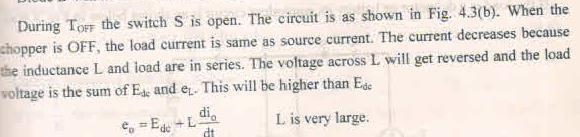
13 Step down chopper When S is ON, e 0 is equal to E dc. When S is OFF, e o is equal to zero. Dr. D G Padhan PSD 13

14 Step up chopper Dr. D G Padhan PSD 14

15 Dr. D G Padhan PSD 15

16 Dr. D G Padhan PSD 16

17 Dr. D G Padhan PSD 17
18 The choppers are also classified based on their regions of operation Single Quadrant chopper 1. Type A Chopper 2. Type B Chopper Two Quadrant Chopper 1. Type C Chopper 2. Type D Chopper Four Quadrant Chopper 1. Type E Chopper Dr. D G Padhan PSD 18

19 First quadrant chopper or Type A chopper Dr. D G Padhan PSD 19

20 The equivalent circuit is shown below Dr. D G Padhan PSD 20


21 Dr. D G Padhan PSD 21

22 Dr. D G Padhan PSD 22

23 Dr. D G Padhan PSD 23
24
25
26

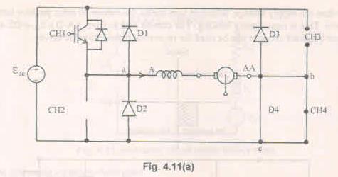
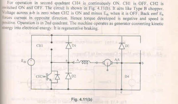
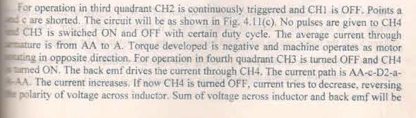
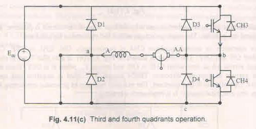
27 Second quadrant or type-b chopper Dr. D G Padhan PSD 27
28 If the chopper (or switch S) is turned ON and turned OFF at regular intervals the average voltage E 0 is +ve and I 0 is ve. The stored energy in the rotor is converted into electrical energy and fed back into the system. This is equivalent to regenerative braking Dr. D G Padhan PSD 28
 Dr.")
29 During the period T ON the switch S ON and hence e 0 =0. The equivalent circuit is shown in Fig.4.6(a) Dr. D G Padhan PSD 29

30 Dr. D G Padhan PSD 30

31 Dr. D G Padhan PSD 31

32 Dr. D G Padhan PSD 32
33 Dr. D G Padhan PSD 33
34 Two-quadrant chopper or Type C chopper V a + T1 D1 V dc i a Q2 Q1 T2 + D2 V a I a - T1 conducts v a = V dc Dr. D G Padhan PSD 34
35 Two-quadrant converter V a + T1 D1 V dc i a Q2 Q1 T2 D2 + V a I a - D2 conducts v a = 0 T1 conducts v a = V dc Quadrant 1 The average voltage is made larger than the back emf Dr. D G Padhan PSD 35
36 Two-quadrant converter V a + T1 D1 V dc i a Q2 Q1 T2 D2 + V a I a - T2 conducts v a = 0 Quadrant 2 The average voltage is made smaller than the back emf, thus forcing the current to flow in the reverse direction Dr. D G Padhan PSD 36
37 Two-quadrant converter V a + T1 D1 V dc i a Q2 Q1 T2 D2 + V a I a - D1 conducts v a = V dc Dr. D G Padhan PSD 37

38 Two quadrant or Type C Chopper Dr. D G Padhan PSD 38
39 Dr. D G Padhan PSD 39

40 Dr. D G Padhan PSD 40

41 Dr. D G Padhan PSD 41

42 Dr. D G Padhan PSD 42

43 Dr. D G Padhan PSD 43

44 Dr. D G Padhan PSD 44

45 Dr. D G Padhan PSD 45

46 Two quadrant chopper- Type D Chopper Dr. D G Padhan PSD 46

47 Dr. D G Padhan PSD 47

48 Dr. D G Padhan PSD 48

49 Dr. D G Padhan PSD 49

50 Dr. D G Padhan PSD 50

51 Dr. D G Padhan PSD 51

52 Dr. D G Padhan PSD 52

53 Dr. D G Padhan PSD 53

54 Dr. D G Padhan PSD 54

55 Dr. D G Padhan PSD 55

56 Dr. D G Padhan PSD 56

57 Dr. D G Padhan PSD 57

58 Dr. D G Padhan PSD 58
59 Chopper fed DC drive Four-quadrant Chopper + Q1 D1 + V a D3 Q3 V a V dc Q2 D2 D4 Q4 I a Forward Motoring Q1 & Q4 is ON Current Flow : V + dc _ Q 1 _Motor_Q 4 _V - dc Current I a & V a are positive Operates in First Quadrant 59
60 Chopper fed DC drive Four-quadrant Chopper + Q1 D1 + V a D3 Q3 V dc Q2 D2 D4 Q4 Q1 is OFF & Q4 is ON. Inductor current has to flow in the same Direction. Diode D2 is FB Inductor Current freewheels through D 2 & Q4 Output Voltage is Zero 60
61 Chopper fed DC drive Four-quadrant Chopper + Q1 D1 + V a D3 Q3 V dc Q2 D2 D4 Q4 Q4 is OFF. Q2 is ON. Load is not connected with the source. Back Emf drives the current through Q2 & D4 61
62 Chopper fed DC drive Four-quadrant Chopper + Q1 D1 + V a D3 Q3 V a V dc Q2 D2 D4 Q4 I a Forward Braking Q2 is OFF. Diode D1 is FB Current flows through D4 & D1 Current Ia is negative & Va is positive. Operates in second quadrant. 62
63 Chopper fed DC drive Four-quadrant Chopper + Q1 D1 - V a + D3 Q3 V dc Q2 D2 D4 Q4 Q3 & Q2 is ON Current Flow : V dc + _ Q 3 _Motor_Q 2 _V dc - Current I a & V a are negative Operates in third Quadrant 63
64 Chopper fed DC drive Four-quadrant Chopper + Q1 D1 - V a + D3 Q3 V dc Q2 D2 D4 Q4 Q3 is OFF. Q2 is ON. Current has to be continuous. Diode D4 is FB Current flows through Q2,D4 & (Eb,La,Ra) 64
65 Chopper fed DC drive Four-quadrant Chopper + Q1 D1 - V a + D3 Q3 V dc Q2 D2 D4 Q4 Q4 Is ON & Q2 is OFF. Back emf Drives the current through Q4 D2 - MOTOR 65
66 Chopper fed DC drive Four-quadrant Chopper + Q1 D1 - V a + D3 Q3 V dc Q2 D2 D4 Q4 Q4 IS Turned Off, D3 is FB Current Flows through Va + - D 3 D 2 Va - Va is negative. But current Ia is positive Operates in fourth quadrant 66

67 Four Quadrant Chopper or Type E Chopper 67
68 68
69 69
70 70
71 71
72 72
73 73
74 74
75 75
76 76
77 77
DC Chopper. Prof. Dr. Fahmy El-khouly
 DC Chopper Prof. Dr. Fahmy El-khouly Definitions: The power electronic circuit which converts directly from dc to dc is called dc-to-dc converter or dc-chopper. Chopper is a dc to dc transformer: The input
VALLIAMMAI ENGINEERING COLLEGE DEPARTMENT OF ELECTRONICS AND INSTRUMENTATION
 VALLIAMMAI ENGINEERING COLLEGE DEPARTMENT OF ELECTRONICS AND INSTRUMENTATION Sem / Branch : V /EIE Subject code /Title: EI2301/Industrial Electronics UNIT-1 POWER DEVICES 1. What are the different methods
Principle Of Step-up Chopper
 Principle Of Step-up Chopper L + D + V Chopper C L O A D V O 1 Step-up chopper is used to obtain a load voltage higher than the input voltage V. The values of L and C are chosen depending upon the requirement
Sascha Stegen School of Electrical Engineering, Griffith University, Australia
 Sascha Stegen School of Electrical Engineering, Griffith University, Australia Electrical Machines and Drives Motors Generators Power Electronics and Drives Open-loop inverter-fed General arrangement of
EE POWER ELECTRONICS
 EE6503 - POWER ELECTRONICS UNIT III - DC TO DC CONVERTER PART A 1.What is meant by time ratio or PWM control (duty cycle) of a DC chopper? (M/J16) The ratio of a period to the total time period is known
DHANALAKSHMI COLLEGE OF ENGINEERING DEPARTMENT OF ELECTRICAL AND ELECTRONICS ENGINEERING
 DHANALAKSHMI COLLEGE OF ENGINEERING DEPARTMENT OF ELECTRICAL AND ELECTRONICS ENGINEERING Power Diode EE2301 POWER ELECTRONICS UNIT I POWER SEMICONDUCTOR DEVICES PART A 1. What is meant by fast recovery
ELECTRONIC CONTROL OF A.C. MOTORS
 CONTENTS C H A P T E R46 Learning Objectives es Classes of Electronic AC Drives Variable Frequency Speed Control of a SCIM Variable Voltage Speed Control of a SCIM Chopper Speed Control of a WRIM Electronic
UNIVERSITY QUESTIONS. Unit-1 Introduction to Power Electronics
 UNIVERSITY QUESTIONS Unit-1 Introduction to Power Electronics 1. Give the symbol and characteristic features of the following devices. (i) SCR (ii) GTO (iii) TRIAC (iv) IGBT (v) SIT (June 2012) 2. What
Published in A R DIGITECH
 DESIGN AND ANALYSIS OF DC-DC BOOST CONVERTER BY USING MATLAB SIMULINK Pund Sunil Kacharu*1,Vivek Kumar Yadav*2 *1(PG Scholar, Assistant Professor, RKDF Bhopal (M.P.)) Sunilpund25@gmail.com,ee.rkdf@gmail.com
11. Define the term pinch off voltage of MOSFET. (May/June 2012)
") Subject Code : EE6503 Branch : EEE Subject Name : Power Electronics Year/Sem. : III /V Unit - I PART-A 1. State the advantages of IGBT over MOSFET. (Nov/Dec 2008) 2. What is the function of snubber circuit?
Subject Code : EE6503 Branch : EEE Subject Name : Power Electronics Year/Sem. : III /V Unit - I PART-A 1. State the advantages of IGBT over MOSFET. (Nov/Dec 2008) 2. What is the function of snubber circuit?
6. Explain control characteristics of GTO, MCT, SITH with the help of waveforms and circuit diagrams.
 POWER ELECTRONICS QUESTION BANK Unit 1: Introduction 1. Explain the control characteristics of SCR and GTO with circuit diagrams, and waveforms of control signal and output voltage. 2. Explain the different
UNIT-III STATOR SIDE CONTROLLED INDUCTION MOTOR DRIVE
 UNIT-III STATOR SIDE CONTROLLED INDUCTION MOTOR DRIVE 3.1 STATOR VOLTAGE CONTROL The induction motor 'speed can be controlled by varying the stator voltage. This method of speed control is known as stator
Investigation and Performance Analysis of Dc-Dc Converter for High Efficiency Led Driver
 IJIRST International Journal for Innovative Research in Science & Technology Volume 2 Issue 12 May 2016 ISSN (online): 2349-6010 Investigation and Performance Analysis of Dc-Dc Converter for High Efficiency
Power Electronics (BEG335EC )
") 1 Power Electronics (BEG335EC ) 2 PURWANCHAL UNIVERSITY V SEMESTER FINAL EXAMINATION - 2003 The figures in margin indicate full marks. Attempt any FIVE questions. Q. [1] [a] A single phase full converter
1 Power Electronics (BEG335EC ) 2 PURWANCHAL UNIVERSITY V SEMESTER FINAL EXAMINATION - 2003 The figures in margin indicate full marks. Attempt any FIVE questions. Q. [1] [a] A single phase full converter
DEVELOPMENT OF A FOUR QUADRANT DC-DC SEPIC CONVERTER MASTER OF SCIENCE IN ELECTRICAL AND ELECTRONIC ENGINEERING BUET
 DEVELOPMENT OF A FOUR QUADRANT DC-DC SEPIC CONVERTER By MD. MAIDUL ISLAM MASTER OF SCIENCE IN ELECTRICAL AND ELECTRONIC ENGINEERING BUET DEPARTMENT OF ELECTRICAL AND ELECTRONIC ENGINEERING BANGLADESH UNIVERSITY
Speed Control of a Dc Motor Using a Chopper Drive
 International Journal of Engineering and Technology Volume 6 No.5, May, 2016 Speed Control of a Dc Motor Using a Chopper Drive Nwosu, A.W 1,Okpagu P.E 2 1 National Engineering Design and Development Institute
Switching and Semiconductor Switches
 1 Switching and Semiconductor Switches 1.1 POWER FLOW CONTROL BY SWITCHES The flow of electrical energy between a fixed voltage supply and a load is often controlled by interposing a controller, as shown
Department of Electrical Engineering, DESCOET Dhamangaon Rly, India
 IJESRT INTERNATIONAL JOURNAL OF ENGINEERING SCIENCES & RESEARCH TECHNOLOGY FOUR QUADRANT SPEED CONTROL OF DC MOTOR USING CHOPPER Devika R. Yengalwar *, Samiksha S. Zade, Dinesh L. Mute * Department of
Power Electronics (Sample Questions) Module-1
 Module-1") Module-1 Short Questions (Previous Years BPUT Questions 1 to 18) 1. What are the conditions for a thyristor to conduct? di 2. What is the common method used for protection? dt 3. What is the importance
Module-1 Short Questions (Previous Years BPUT Questions 1 to 18) 1. What are the conditions for a thyristor to conduct? di 2. What is the common method used for protection? dt 3. What is the importance
2 Marks - Question Bank. Unit 1- INTRODUCTION
 Two marks 1. What is power electronics? EE6503 POWER ELECTRONICS 2 Marks - Question Bank Unit 1- INTRODUCTION Power electronics is a subject that concerns the applications electronics principles into situations
Speed Torque Characteristic Of Dc Motor Fed By H Bridge Converter
 Speed Torque Characteristic Of Dc Motor Fed By H Bridge Converter Manjunath B. Ranadev *1, R. L. Chakrasali 2 EEE Department, KLE Institute of Technology, Hubli, Karnataka, India EEE Department, SDM College
DOWNLOAD PDF POWER ELECTRONICS DEVICES DRIVERS AND APPLICATIONS
 Chapter 1 : Power Electronics Devices, Drivers, Applications, and Passive theinnatdunvilla.com - Google D Download Power Electronics: Devices, Drivers and Applications By B.W. Williams - Provides a wide
DHANALAKSHMI SRINIVASAN COLLEGE OF ENGINEERING AND TECHNOLY Mamallapuram chennai
 DHANALAKSHMI SRINIVASAN COLLEGE OF ENGINEERING AND TECHNOLY Mamallapuram chennai DEPARTMENT OF ELECTRICAL AND ELECTRONICS ENGINEERING QUESTION BANK V SEMESTER EE6503 - POWER ELECTRONICS Regulation 2013
EEL 646 POWER ELECTRONICS II. Issa Batarseh. January 13, 2015
 EEL 646 POWER ELECTRONICS II Issa Batarseh January 13, 2015 Agenda About the course Syllabus Review Course Topics Review of Power Electronics I Questions Introduction (cont d) Introduction (cont d) 5
Modeling and Simulation of a DC-DC Boost converter and its performance analysis based on various parameters
 Modeling and Simulation of a DC-DC Boost converter and its performance analysis based on various parameters 1 Poonam Verma, 2 Dr. M. K. Bhaskar, Surbhi Bhandari 3 1 PG Scholar, 2 Professor, 3 Assistant
(a) average output voltage (b) average output current (c) average and rms values of SCR current and (d) input power factor. [16]
![(a) average output voltage (b) average output current (c) average and rms values of SCR current and (d) input power factor. [16]](/thumbs/81/83006678.jpg "(a) average output voltage (b) average output current (c) average and rms values of SCR current and (d) input power factor. [16]") Code No: 07A50204 R07 Set No. 2 1. A single phase fully controlled bridge converter is operated from 230 v, 50 Hz source. The load consists of 10Ω and a large inductance so as to reach the load current
Code No: 07A50204 R07 Set No. 2 1. A single phase fully controlled bridge converter is operated from 230 v, 50 Hz source. The load consists of 10Ω and a large inductance so as to reach the load current
Module 4. AC to AC Voltage Converters. Version 2 EE IIT, Kharagpur 1
 Module 4 AC to AC Voltage Converters Version EE IIT, Kharagpur 1 Lesson 9 Introduction to Cycloconverters Version EE IIT, Kharagpur Instructional Objectives Study of the following: The cyclo-converter
EPC2201 Power Electronic Devices Tutorial Sheet
 EPC2201 Power Electronic Devices Tutorial heet 1. The ON state forward voltage drop of the controlled static switch in Figure 1 is 2V. Its forward leakage current in the state is 2mA. It is operated with
A New Single Source Topology Four Quadrant DC-DC SEPIC Converter
 American Journal of Electrical and Electronic Engineering, 2016, Vol. 4, No. 5, 131-138 Available online at http://pubs.sciepub.com/ajeee/4/5/2 Science and Education Publishing DO:10.12691/ajeee-4-5-2
Fig.1. A Block Diagram of dc-dc Converter System
 ANALYSIS AND SIMULATION OF BUCK SWITCH MODE DC TO DC POWER REGULATOR G. C. Diyoke Department of Electrical and Electronics Engineering Michael Okpara University of Agriculture, Umudike Umuahia, Abia State
Type of loads Active load torque: - Passive load torque :-
 Type of loads Active load torque: - Active torques continues to act in the same direction irrespective of the direction of the drive. e.g. gravitational force or deformation in elastic bodies. Passive
Digital Combination of Buck and Boost Converters to Control a Positive Buck Boost Converter and Improve the Output Transients K.
 Digital Combination of Buck and Boost Converters to Control a Positive Buck Boost Converter and Improve the Output Transients K. prasannakumar Student(M.Tech), Electrical Dept, Gokul group of institutions,
INSTITUTE OF AERONAUTICAL ENGINEERING (Autonomous) Dundigal, Hyderabad
 Dundigal, Hyderabad") I INSTITUTE OF AERONAUTICAL ENGINEERING (Autonomous) Dundigal, Hyderabad-000 DEPARTMENT OF ELECTRICAL AND ELECTRONICS ENGINEERING TUTORIAL QUESTION BANK Course Name : POWER ELECTRONICS Course Code : AEE0
I INSTITUTE OF AERONAUTICAL ENGINEERING (Autonomous) Dundigal, Hyderabad-000 DEPARTMENT OF ELECTRICAL AND ELECTRONICS ENGINEERING TUTORIAL QUESTION BANK Course Name : POWER ELECTRONICS Course Code : AEE0
POWER ELECTRONICS PO POST GRAD POS UATE 2010 AC Ch AC o Ch p o per Prepare Prep d are by: d Dr. Gamal Gam SOwilam SOwila 11 December 2016 ١
 POWER ELECTRONICS POST GRADUATE 2010 AC Chopper Prepared by: Dr. Gamal SOwilam 11 December 2016 ١ 1. Introduction AC Chopper is An AC to AC Converter employs to vary the rms voltage across the load at
 POWER ELECTRONICS TWO MARK QUESTIONS & ANSWERS Class : V SEM EEE UNIT I 1. What is power electronics? Power electronics is a subject that concerns the applications electronics principles into situations
Analysis of Soft-switching Converters for Switched Reluctance Motor Drives for Electric Vehicles
 Journal of sian Electric Vehicles, Volume 7, Number 1, June 2009 nalysis of Soft-switching Converters for Switched Reluctance Motor Drives for Electric Vehicles Tze Wood Ching Department of Electromechanical
Power Electronics. Electrical Engineering. for
 Power Electronics for Electrical Engineering By www.thegateacademy.com Syllabus Syllabus for Power Electronics Characteristics of Semiconductor Power Devices: Diode, Thyristor, Triac, GTO, MOSFET, IGBT;
Name of chapter & details
 Course Title Course Code Power Electronics-I EL509 Lecture : 03 / 03 Course Credit / Hours Practical : 01 / 02 Tutorial : 00 / 00 Course Learning Outcomes Total : 04 / 05 At the end of the session student
Design and Hardware Implementation of L-Type Resonant Step Down DC-DC Converter using Zero Current Switching Technique
 Design and Hardware Implementation of L-Type Resonant Step Down DC-DC Converter using Zero Current Switching Technique Mouliswara Rao. R Assistant Professor, Department of EEE, AITAM, Tekkali, Andhra Pradesh,
16 Basic Control Systems
 16 Basic Control Systems 16.1 Power Semiconductor-Controlled Drives 16.2 Feedback Control Systems 16.3 Digital Control Systems 16.4 Learning Objectives 16.5 Practical Application: A Case Study Digital
Dr.Arkan A.Hussein Power Electronics Fourth Class. Operation and Analysis of the Three Phase Fully Controlled Bridge Converter
 Operation and Analysis of the Three Phase Fully Controlled Bridge Converter ١ Instructional Objectives On completion the student will be able to Draw the circuit diagram and waveforms associated with a
CHOICE OF HIGH FREQUENCY INVERTERS AND SEMICONDUCTOR SWITCHES
 Chapter-3 CHOICE OF HIGH FREQUENCY INVERTERS AND SEMICONDUCTOR SWITCHES This chapter is based on the published articles, 1. Nitai Pal, Pradip Kumar Sadhu, Dola Sinha and Atanu Bandyopadhyay, Selection
MAHARASHTRA STATE BOARD OF TECHNICAL EDUCATION
 Important Instructions to examiners: 1) The answers should be examined by key words and not as word-to-word as given in the model answer scheme. 2) The model answer and the answer written by candidate
UNIT I POWER SEMI-CONDUCTOR DEVICES
 UNIT I POWER SEMI-CONDUCTOR DEVICES SUBJECT CODE SUBJECT NAME STAFF NAME : EE6503 : Power Electronics : Ms.M.Uma Maheswari 1 SEMICONDUCTOR DEVICES POWER DIODE POWER TRANSISTORS POWER BJT POWER MOSFET IGBT
Module 1. Power Semiconductor Devices. Version 2 EE IIT, Kharagpur 1
 Module 1 Power Semiconductor Devices Version EE IIT, Kharagpur 1 Lesson 8 Hard and Soft Switching of Power Semiconductors Version EE IIT, Kharagpur This lesson provides the reader the following (i) (ii)
ELECTRIC DRIVE LAB Laboratory Manual
 DEV BHOOMI INSTITUTE OF TECHNOLOGY CHAKRATA ROAD, NAVGAOUN MANDUWALA, UTTARAKHAND Programs: B.TECH. (Electrical and Electronics Engineering) ELECTRIC DRIVE LAB Laboratory Manual PREPARED BY ASHISH KUKRETI,
A Highly Versatile Laboratory Setup for Teaching Basics of Power Electronics in Industry Related Form
 A Highly Versatile Laboratory Setup for Teaching Basics of Power Electronics in Industry Related Form JOHANN MINIBÖCK power electronics consultant Purgstall 5 A-3752 Walkenstein AUSTRIA Phone: +43-2913-411
Lecture 19 - Single-phase square-wave inverter
 Lecture 19 - Single-phase square-wave inverter 1. Introduction Inverter circuits supply AC voltage or current to a load from a DC supply. A DC source, often obtained from an AC-DC rectifier, is converted
POWER ELECTRONICS. Alpha. Science International Ltd. S.C. Tripathy. Oxford, U.K.
 POWER ELECTRONICS S.C. Tripathy Alpha Science International Ltd. Oxford, U.K. Contents Preface vii 1. SEMICONDUCTOR DIODE THEORY 1.1 1.1 Introduction 1.1 1.2 Charge Densities in a Doped Semiconductor 1.1
PF and THD Measurement for Power Electronic Converter
 PF and THD Measurement for Power Electronic Converter Mr.V.M.Deshmukh, Ms.V.L.Jadhav Department name: E&TC, E&TC, And Position: Assistant Professor, Lecturer Email: deshvm123@yahoo.co.in, vandanajadhav19jan@gmail.com
Lecture 16: Four Quadrant operation of DC Drive (or) TYPE E Four Quadrant chopper Fed Drive: Operation
 TYPE E Four Quadrant chopper Fed Drive: Operation") Lecture 16: Four Qudrnt opertion of DC Drive (or) TYPE E Four Qudrnt chopper Fed Drive: Opertion The rmture current I is either positive or negtive (flow in to or wy from rmture) the rmture voltge is lso
Lecture 16: Four Qudrnt opertion of DC Drive (or) TYPE E Four Qudrnt chopper Fed Drive: Opertion The rmture current I is either positive or negtive (flow in to or wy from rmture) the rmture voltge is lso
Electric cars: Technology
 Key equations for a boost converter Now that you have an understanding of how the simple DC-DC boost converter works, we summarize the main equations for the converter here. These equations are for continuous
The High Power IGBT Current Source Inverter
 The High Power IGBT Current Source Inverter Muhammad S. Abu Khaizaran, Haile S. Rajamani * and Patrick R. Palmer Department of Engineering University of Cambridge Trumpington Street Cambridge CB PZ, UK
Workshop Matlab/Simulink in Drives and Power electronics Lecture 4
 Workshop Matlab/Simulink in Drives and Power electronics Lecture 4 : DC-Motor Chopper design SimPowerSystems Ghislain REMY Jean DEPREZ 1 / 20 Workshop Program 8 lectures will be presented based on Matlab/Simulink
Closed Loop Single Phase Bidirectional AC to AC Buck Boost Converter for Power Quality Improvement
 International Journal of Engineering Research and Development e-issn: 2278-067X, p-issn: 2278-800X, www.ijerd.com Volume 7, Issue 11 (July 2013), PP. 35-42 Closed Loop Single Phase Bidirectional AC to
The typical ratio of latching current to holding current in a 20 A thyristor is (A) 5.0 (B) 2.0 (C) 1.0 (D) 0.5
 5.0 (B) 2.0 (C) 1.0 (D) 0.5") CHAPTER 9 POWER ELECTRONICS YEAR 0 ONE MARK MCQ 9. MCQ 9. A half-controlled single-phase bridge rectifier is supplying an R-L load. It is operated at a firing angle α and the load current is continuous.
CHAPTER 9 POWER ELECTRONICS YEAR 0 ONE MARK MCQ 9. MCQ 9. A half-controlled single-phase bridge rectifier is supplying an R-L load. It is operated at a firing angle α and the load current is continuous.
Electrical Engineering EE / EEE. Postal Correspondence Course. Power Electronics. GATE, IES & PSUs
 Power Electronics-EE GATE, IES, PSU 1 SAMPLE STUDY MATERIAL Electrical Engineering EE / EEE Postal Correspondence Course Power Electronics GATE, IES & PSUs Power Electronics-EE GATE, IES, PSU 2 C O N T
LENDI INSTITUTE OF ENGINEERING & TECHNOLOGY
 LENDI INSTITUTE OF ENGINEERING & TECHNOLOGY (Approved by A.I.C.T.E & Affiliated to JNTU,Kakinada) Jonnada (Village), Denkada (Mandal), Vizianagaram Dist 535 005 Phone No. 08922-241111, 241112 E-Mail: lendi_2008@yahoo.com
Switches And Antiparallel Diodes
 H-bridge Inverter Circuit With Transistor Switches And Antiparallel Diodes In these H-bridges we have implemented MOSFET transistor for switching. sub-block contains an ideal IGBT, Gto or MOSFET and antiparallel
Implementation of Multiquadrant D.C. Drive Using Microcontroller
 Implementation of Multiquadrant D.C. Drive Using Microcontroller Author Seema Telang M.Tech. (IV Sem.) Department of Electrical Engineering Shri Ramdeobaba College of Engineering and Management Abstract
Lesson 1 of Chapter Three Single Phase Half and Fully Controlled Rectifier
 Lesson of Chapter hree Single Phase Half and Fully Controlled Rectifier. Single phase fully controlled half wave rectifier. Resistive load Fig. :Single phase fully controlled half wave rectifier supplying
UNIT-I CONTROL OF DC MOTORS THROUGH PHJASE CONTROLLED RECTIFIERS
 UNIT-I CONTROL OF DC MOTORS THROUGH PHJASE CONTROLLED RECTIFIERS Electrical Drives: Motion control is required in large number of industrial and domestic applications like transportation systems, rolling
INVESTIGATION OF BOOST AND INTERLEAVED BOOST SWITCHED MODE RECTIFIERS FOR POWER FACTOR CORRECTION
 INVESTIGATION OF BOOST AND INTERLEAVED BOOST SWITCHED MODE RECTIFIERS FOR POWER FACTOR CORRECTION 1 V.AISHWARYA, 2 C.KAVITHA, 3 R.KAVIYA, 4 R.SEYEZHAI 1,2,3 UG Students, Department of EEE, SSN College
Development of a Single-Phase PWM AC Controller
 Pertanika J. Sci. & Technol. 16 (2): 119-127 (2008) ISSN: 0128-7680 Universiti Putra Malaysia Press Development of a Single-Phase PWM AC Controller S.M. Bashi*, N.F. Mailah and W.B. Cheng Department of
High Voltage DC Transmission 2
 High Voltage DC Transmission 2 1.0 Introduction Interconnecting HVDC within an AC system requires conversion from AC to DC and inversion from DC to AC. We refer to the circuits which provide conversion
COMPARATIVE STUDY ON DC-DC CONVERTERS
 COMPARATIVE STUDY ON DC-DC CONVERTERS BY MEHEDI HASAN TUSHAR ID-09221205 THESIS FINAL SEMESTER SUPERVISOR: Amina Hasan Abedin ACKNOWLEDGEMENTS I wish to extend my sincere appreciation to my adviser Amina
Experiment DC-DC converter
 POWER ELECTRONIC LAB Experiment-7-8-9 DC-DC converter Power Electronics Lab Ali Shafique, Ijhar Khan, Dr. Syed Abdul Rahman Kashif 10/11/2015 This manual needs to be completed before the mid-term examination.
Speed Control of DC Motor Using Soft Starter: A Review
 IOSR Journal of Engineering (IOSRJEN) ISSN (e): 2250-3021, ISSN (p): 2278-8719 Volume 8, PP 61-66 www.iosrjen.org Speed Control of DC Motor Using Soft Starter: A Review Saurav Shama 1, Vivek Ghadge 2,
( ) ON s inductance of 10 mh. The motor draws an average current of 20A at a constant back emf of 80 V, under steady state.
 ON s inductance of 10 mh. The motor draws an average current of 20A at a constant back emf of 80 V, under steady state.") 1991 1.12 The operating state that distinguishes a silicon controlled rectifier (SCR) from a diode is (a) forward conduction state (b) forward blocking state (c) reverse conduction state (d) reverse blocking
1991 1.12 The operating state that distinguishes a silicon controlled rectifier (SCR) from a diode is (a) forward conduction state (b) forward blocking state (c) reverse conduction state (d) reverse blocking
A Three-Phase AC-AC Buck-Boost Converter using Impedance Network
 A Three-Phase AC-AC Buck-Boost Converter using Impedance Network Punit Kumar PG Student Electrical and Instrumentation Engineering Department Thapar University, Patiala Santosh Sonar Assistant Professor
Power Electronics Power semiconductor devices. Dr. Firas Obeidat
 Power Electronics Power semiconductor devices Dr. Firas Obeidat 1 Table of contents 1 Introduction 2 Classifications of Power Switches 3 Power Diodes 4 Thyristors (SCRs) 5 The Triac 6 The Gate Turn-Off
Design and Simulation of Synchronous Buck Converter for Microprocessor Applications
 Design and Simulation of Synchronous Buck Converter for Microprocessor Applications Lakshmi M Shankreppagol 1 1 Department of EEE, SDMCET,Dharwad, India Abstract: The power requirements for the microprocessor
ANALYSIS OF POWER QUALITY IMPROVEMENT OF BLDC MOTOR DRIVE USING CUK CONVERTER OPERATING IN DISCONTINUOUS CONDUCTION MODE
 ANALYSIS OF POWER QUALITY IMPROVEMENT OF BLDC MOTOR DRIVE USING CUK CONVERTER OPERATING IN DISCONTINUOUS CONDUCTION MODE Bhushan P. Mokal 1, Dr. K. Vadirajacharya 2 1,2 Department of Electrical Engineering,Dr.
Jaykishan H. Moradiya 1, Assistant Prof. Niraj B. Danidhariya 2
 Design and Simulation of Closed Loop Speed Control of DC Drives by Using Dual Converter Jaykishan H. Moradiya 1, Assistant Prof. Niraj B. Danidhariya 2 1 Electrical Engineering, AITSRajkot, jekymoradiya@gmail.com
Selective Harmonic Elimination (SHE) for 3-Phase Voltage Source Inverter (VSI)
 for 3-Phase Voltage Source Inverter (VSI)") Selective Elimination (SHE) for 3-Phase Voltage Source Inverter (VSI) V.Karthikeyan, SVS College of Engineering, Coimbatore, India karthick77keyan@gmail.com V.J.Vijayalakshmi, Sri Krishna College of Engg
Selective Elimination (SHE) for 3-Phase Voltage Source Inverter (VSI) V.Karthikeyan, SVS College of Engineering, Coimbatore, India karthick77keyan@gmail.com V.J.Vijayalakshmi, Sri Krishna College of Engg
ELG4139: Power Electronics Systems Objective To Realize and Design Various Power Supplies and Motor Drives!
 ELG4139: Power Electronics Systems Objective To Realize and Design Various Power Supplies and Motor Drives! Power electronics refers to control and conversion of electrical power by power semiconductor
ELEC4240/ELEC9240 POWER ELECTRONICS
 THE UNIVERSITY OF NEW SOUTH WALES FINAL EXAMINATION JUNE/JULY, 2003 ELEC4240/ELEC9240 POWER ELECTRONICS 1. Time allowed: 3 (three) hours 2. This paper has six questions. Answer any four. 3. All questions
Literature Review. Chapter 2
 Chapter 2 Literature Review Research has been carried out in two ways one is on the track of an AC-AC converter and other is on track of an AC-DC converter. Researchers have worked in AC-AC conversion
Other Electronic Devices
 Other Electronic Devices 1 Contents Field-Effect Transistors(FETs) - JFETs - MOSFETs Insulate Gate Bipolar Transistors(IGBTs) H-bridge driver and PWM Silicon-Controlled Rectifiers(SCRs) TRIACs Device Selection
ANALYSIS, SIMULATION AND HARDWARE IMPLEMENTATION OF BOOST DC-DC CONVERTER
 ANALYSIS, SIMULATION AND HARDWARE IMPLEMENTATION OF BOOST DC-DC CONVERTER A.Thiyagarajan Assistant Professor,Department of Electrical and Electronics Engineering, Karpagam Institute of Technology, Coimbatore,
Lecture 23 Review of Emerging and Traditional Solid State Switches
 Lecture 23 Review of Emerging and Traditional Solid State Switches 1 A. Solid State Switches 1. Circuit conditions and circuit controlled switches A. Silicon Diode B. Silicon Carbide Diodes 2. Control
8/4/2011. Electric Machines & Drives. Chapter 21 Example of gating pulses on SCR condition
 Welcome to Electric Machines & Drives thomasblairpe.com/emd Session 10 Fundamental Elements of Power Electronics (Part 2) USF Polytechnic Engineering tom@thomasblairpe.com Session 10: Power Electronics
Thyristors. In this lecture you will learn the following. Module 4 : Voltage and Power Flow Control. Lecture 18a : HVDC converters.
 Module 4 : Voltage and Power Flow Control Lecture 18a : HVDC converters Objectives In this lecture you will learn the following AC-DC Converters used for HVDC applications. Introduction to Voltage Source
SiC-JFET in half-bridge configuration parasitic turn-on at
 SiC-JFET in half-bridge configuration parasitic turn-on at current commutation Daniel Heer, Infineon Technologies AG, Germany, Daniel.Heer@Infineon.com Dr. Reinhold Bayerer, Infineon Technologies AG, Germany,
ELEC387 Power electronics
 ELEC387 Power electronics Jonathan Goldwasser 1 Power electronics systems pp.3 15 Main task: process and control flow of electric energy by supplying voltage and current in a form that is optimally suited
Prof. Steven S. Saliterman Introductory Medical Device Prototyping
 Introductory Medical Device Prototyping Department of Biomedical Engineering, University of Minnesota http://saliterman.umn.edu/ Solid state power switching: Silicon controlled rectifiers (SCR or Thyristor).
CHAPTER-III MODELING AND IMPLEMENTATION OF PMBLDC MOTOR DRIVE
 CHAPTER-III MODELING AND IMPLEMENTATION OF PMBLDC MOTOR DRIVE 3.1 GENERAL The PMBLDC motors used in low power applications (up to 5kW) are fed from a single-phase AC source through a diode bridge rectifier
PID CONTROLLER BASED FULL BRIDGE DC-DC CONVERTER FOR CLOSED LOOP DC MOTOR WITH UNIPOLAR VOLTAGE SWITCHING
 U.P.B. Sci. Bull., Series C, Vol. 77, Iss. 1, 2015 ISSN 2286 3540 PID CONTROLLER BASED FULL BRIDGE DC-DC CONVERTER FOR CLOSED LOOP DC MOTOR WITH UNIPOLAR VOLTAGE SWITCHING P. KARPAGAVALLI 1, A. EBENEZER
Power Electronics. P. T. Krein
 Power Electronics Day 10 Power Semiconductor Devices P. T. Krein Department of Electrical and Computer Engineering University of Illinois at Urbana-Champaign 2011 Philip T. Krein. All rights reserved.
Harmonic Analysis of a Specified output voltage with improved power quality AC -DC dual converter fed four quadrant DC Drive
 Harmonic Analysis of a Specified output voltage with improved power quality AC -DC dual converter fed four quadrant DC Drive 1 B.Praveen Kumar, 2 S.Rajshekar, 3 M.V.Subrahmanyam 1 & 2 Electrical Department,
POWER ELECTRONICS LAB
 MUFFAKHAM JAH COLLEGE OF ENGINEERING & TECHNOLOGY Banjara Hills Road No 3, Hyderabad 34 www.mjcollege.ac.in DEPARTMENT OF ELECTRICAL ENGINEERING LABORATORY MANUAL POWER ELECTRONICS LAB For B.E. III/IV
UNIVERSITY OF TECHNOLOGY
 UNIVERSITY OF TECHNOLOGY Third Year DEPARTMENT OF ELECTRICAL ENGINEERING Electronics Engineering Section AC Machine and Power Electronics 2016-2017 Module-II: Power Electronics: Power electronics devices
Chapter 6 Soft-Switching dc-dc Converters Outlines
 Chapter 6 Soft-Switching dc-dc Converters Outlines Classification of soft-switching resonant converters Advantages and disadvantages of ZCS and ZVS Zero-current switching topologies The resonant switch
Design and Simulation of Three Phase Controlled Rectifier Using IGBT
 Design and Simulation of Three Phase Controlled Rectifier Using IGBT Tanmay Sharma 1, Dhruvi Dave 2, Ruchit Soni 3 1 Student, Electrical Engineering Department, Indus University, Ahmedabad, Gujarat. 2
CHAPTER 1 DIODE CIRCUITS. Semiconductor act differently to DC and AC currents
 CHAPTER 1 DIODE CIRCUITS Resistance levels Semiconductor act differently to DC and AC currents There are three types of resistances 1. DC or static resistance The application of DC voltage to a circuit
INTERNATIONAL JOURNAL OF ENHANCED RESEARCH IN SCIENCE TECHNOLOGY & ENGINEERING VOL. 2 ISSUE 2, FEB ISSN NO:
 Single Phase Neutral Point Diode Clamped Active Rectifier - A Literature Review Naveesh Kant Sharma 1, Susheva Sharma 2, Vikrant Sharma 3, Ashish Sharma 4 1,2,3 M. Tech Scholar, Electrical Engineering,
CHAPTER 2 CURRENT SOURCE INVERTER FOR IM CONTROL
 9 CHAPTER 2 CURRENT SOURCE INVERTER FOR IM CONTROL 2.1 INTRODUCTION AC drives are mainly classified into direct and indirect converter drives. In direct converters (cycloconverters), the AC power is fed
Design and Implementation of AC Chopper
 International Journal of Emerging Engineering Research and Technology Volume 2, Issue 1, April 2014, PP 36-41 Design and Implementation of AC Chopper P.Sravan Kumar 1, Assistant Professor B.Mahendar 2,
International Journal of Advancements in Research & Technology, Volume 7, Issue 4, April-2018 ISSN
 ISSN 2278-7763 22 A CONVENTIONAL SINGLE-PHASE FULL BRIDGE CURRENT SOURCE INVERTER WITH LOAD VARIATION 1 G. C. Diyoke *, 1 C. C. Okeke and 1 O. Oputa 1 Department of Electrical and Electronic Engineering,
(12) Patent Application Publication (10) Pub. No.: US 2005/ A1
 Patent Application Publication (10) Pub. No.: US 2005/ A1") (19) United States (12) Patent Application Publication (10) Pub. No.: Su US 2005O127853A1 (43) Pub. Date: Jun. 16, 2005 (54) (76) (21) (22) (51) MULTI-LEVEL DC BUS INVERTER FOR PROVIDING SNUSODAL AND PWM
(19) United States (12) Patent Application Publication (10) Pub. No.: Su US 2005O127853A1 (43) Pub. Date: Jun. 16, 2005 (54) (76) (21) (22) (51) MULTI-LEVEL DC BUS INVERTER FOR PROVIDING SNUSODAL AND PWM