Product Specification
|
|
|
- Lorraine Preston
- 6 years ago
- Views:
Transcription

1 Product Specification Polymer Li-ion Battery 3.7V 6350mAh 5C (Model No.:SLPBA836) Shenzhen Melasta Battery Co.,Ltd Tongfuyu Industrial Zone,Dalang,BaoAn District,Shenzhen,5809,China Tel: Fax: MELASTA 锂聚合物电池 LIPO BATTERIES July 3, 03 This information is generally descriptive only and is not intended to make or imply any representation, guarantee or warranty with respect to any cells and batteries. Cell and battery designs/specifications are subject to modification without notice. Contact MELASTA for the latest information. All 9 sheets
2 深圳风云电池技术有限公司 SHENZHEN MELASTA BATTERY CO., LTD 产品规格书 (Product Specification) 型号 (Model No.)SLPBA mAh 5C 3.7V Content 目录. 序言 3 Preface. 型号 :SLPBA836 3 Model: SLPBA 产品规格 3 Specification. 电芯性能检查及测试 Battery Cell Performance Criteria 5. 贮存及其它事项 5 Storage and Others 6. 聚合物锂离子充电电芯操作指示及注意事项 5-8 Handling Precautions and Guideline 6.. 充电 5-6 Charging 6.. 放电 6-7 Discharging 6.3. 贮存 7 Storage 6.. 电芯操作注意事项 7 Handling of Cells 6.5. 电池外壳设计注意事项 7 Notice for Designing Battery Pack 6.6. 电池与外壳组装注意事项 7-8 Notice for Assembling Battery Pack 7. 其它事项 8-9 Others 制造商保留在没有预先通知的情况下改变和修正设计及规格说明书的权力 Melasta reserves the right to alter or amend the design, model and specification without prior notice
3 深圳风云电池技术有限公司 SHENZHEN MELASTA BATTERY CO., LTD 产品规格书 (Product Specification) 型号 (Model No.)SLPBA mAh 5C 3.7V. 序言 PREFACE 此规格书适用于深圳风云电池有限公司的锂聚合物可充电电池产品 The specification is suitable for the performance of Lithium-Polymer (LIP) rechargeable battery produced by the SHENZHEN MELASTA BATTERY CO., LTD.. 型号 MODEL SLPBA mAh 5C 3.7V 3. 产品规格 SPECIFICATION 单颗电池规格 Specifications of single cell Distance between ± tabs ±0. Tab width ± L 6± 标称容量 Typical Capacity 6.35Ah 标称电压 Nominal Voltage 3.7V 充电条件 Charge Condition 放电条件 Discharge Condition 最大电流 Max. Continuous charge Current 峰值充电 Peak Charge current 电压 Voltage Max Continuous discharge Current Peak Discharge Current.7A 5.A( sec).v±0.03v 95.5A 7A Cut-off Voltage 3.0V 交流内阻 AC Impedance(mOHM).0 循环寿命 充电 :.0C, 放电 :5C 00cycles Cycle Life CHA:.0C,DCH:5C 使用温度充电 Charge 0 ~5 Operating Temp. 放电 Discharge -0 ~60 厚度 Thickness(T) 0.5±0.3mm W T 电芯尺寸 Cell Dimensions 极耳尺寸 Dimensions of Cell tabs 宽度 Width(W) 长度 Length(L) 极耳间距 Distance between tabs 极耳宽度 Tab Width 极耳厚度 Tab Thickness 极耳长度 Tab Length 制造商保留在没有预先通知的情况下改变和修正设计及规格说明书的权力 Melasta reserves the right to alter or amend the design, model and specification without prior notice.7±0.5mm 7.5±0.5mm ±mm 5mm 0.mm 5mm 重量 Weight(g) 3± 标称容量 :0.5CmA,.V~3.0V@3 ± Typical Capacity:0.5CmA,.V~3.0V@3 ± 3
4 深圳风云电池技术有限公司 SHENZHEN MELASTA BATTERY CO., LTD 产品规格书 (Product Specification) 型号 (Model No.)SLPBA mAh 5C 3.7V. 电芯性能检查及测试 BATTERY CELL PERFORMANCE CRITERIA 在进行下例各项测试前每颗电池应用 0.5C 放至 3.0V 如果没有特别规定, 测试应在电池交付 个月内按以下各项条件进行 : Before proceed the following tests, the cells should be discharged at 0.C to 3.0V cut off. Unless otherwise stated, tests should be done within one month of delivery under the following conditions: 环境温度 Ambient temperature: 0 ±5 相对湿度 Relative Humidity: 65±0%RH 注意标准充放电为 Note Standard Charge/Discharge Conditions: 充电 Charge: 以 0.5C 电流恒流充电至限制电压.V 时, 改为恒压充电, 直到截止电流为 0.05C 时停止充电 ;The battery will be charged to.v with 0.5C from constant current to constant voltage, when the current is 0.05C, stop to charge.; 放电 Discharge: 0.5C to 3.0V/cell 测试项目 Test 容量 Capacity 开路电压 Open Circuit Voltage (OCV) 单位 Unit mah 规格 Specification 6350 V.5 条件 Condition 标准充放电 Standard Charge / Discharge 标准充电后 个小时内 Within hr after standard charge 备注 Remarks 允许循环 3 次 Up to 3 cycles are allowed 单位颗 Unit cell 内阻 Internal Impedance (IR) 高倍率放电 High Rate Discharge (5C) 低温放电 Low Temperature Discharge 自放电 Charge Reserve 寿命测试 Cycle Life Test 短路测试 External Short Circuit mω.0 min 3.6 min min Cycle N/A 0 90% ( 初始容量 First Capacity) 00 不着火不爆炸 No Fire and No Explosion 充满电后用 khz 测试 Upon fully charge at khz 标准充电 / 休息 5 分钟用 5C 放电至 3.0V Standard Charge/rest 5min discharge at 5C to 3.0V 标准充电后贮藏在 -0± 环境中 小时然后用 0.C 放电 Standard Charge, Storage:hrs at- 0± 0.C discharge at 0± 标准充满电后 0 度贮藏 30 天, 标准 0.5C 放电 Standard charge Storage at 0 degree: 30days Standard discharge (0.5C) 充电 :C 充电至.V, 放电,5C 放电至 3.0V, 当放电容量降至初始容量的 80% 时, 所完成的循环次数定义为该电芯的循环寿命 Charge:0.5C to.v,discharge: C to 3.0V, 80% or more of st cycle capacity at 5C discharge of Operation 标准充电后, 在 0 ±5 环境中用超过 0.75mm 金属丝将单颗电池短路至电池恢复到常温 After standard charge, short-circuit the cell at 0 ±5 until the cell temperature returns to ambient temperature.(cross section of the wire or connector should be more than 0.75mm ) * 允许循环 3 次 Up to 3 cycles are allowed 3.0V/cell Cut-off 3.0V/cell Cut-off * Retention capacity 容量保持 80% of initial capacity 制造商保留在没有预先通知的情况下改变和修正设计及规格说明书的权力 Melasta reserves the right to alter or amend the design, model and specification without prior notice
5 深圳风云电池技术有限公司 SHENZHEN MELASTA BATTERY CO., LTD 产品规格书 (Product Specification) 型号 (Model No.)SLPBA mAh 5C 3.7V 自由跌落测试 Free Falling(drop) N/A 不着火不爆炸 No Fire and No Explosion 5. 贮存及其它事项 STORAGE AND OTHERS 5. 环境温度 Ambient temperature: 0 ±5 跌标准充电后, 搁置 小时 从 50CM 高任意方向自由跌落 30MM 厚木板 3 次 Standard Charge,and then leave for hrs,check battery before / after drop Height: 50 cm Thickness of wooden board: 30mm Direction is not specified Test for 3 times * 相对湿度 Relative Humidity: 65±0%RH 5. 请每隔 3 个月按下面方法激活电池一次 : Please activate the battery once every 3 months according to the following method: 0.C 充电至.V, 休息 5 分钟, 然后用 0.C 放电至每颗电池 3.0V, 休息 5 分钟,0.C 充电 3.9V Charge at 0.C to.v, rest 5 min, then discharge with 0.C to 3.0V/cell,rest 5 min, then charge at 0.C to 3.9V. 6. 聚合物锂离子充电电芯操作指示及注意事项 HANDLING PRECAUTIONS AND GUIDLINE 声明一 : Note(): 客户若需要将电芯用于超出文件规定以外的设备, 或在文件规定以外的使用条件下使用电芯, 应事先联系鸿 星, 因为需要进行特定的实验测试以核实电芯在该使用条件下的性能及安全性 The customer is requested to contact MELASTA in advance, if and when the customer needs other applications or operating conditions than those described in this document. Additional experimentation may be required to verify performance and safety under such conditions. 声明二 : Note(): 对于在超出文件规定以外的条件下使用电芯而造成的任何意外事故, 风云公司概不负责 MELASTA will take no responsibility for any accident when the cell is used under other conditions than those described in this Document. 声明三 : 如有必要, 风云公司会以书面形式告之客户有关正确操作使用电芯的改进措施 MELASTA will inform, in a written form, the customer of improvement(s) regarding proper use and handing of the cell, if it is deemed necessary. 6.. 充电 Charging 6.. 充电电流 Charging current: 充电电流不得超过本标准书中规定的最大充电电流 使用高于推荐值电流充电将可能引起电芯的充放电性 能 机械性能和安全性能的问题, 并可能会导致发热或泄漏 Charging current should be less than maximum charge current specified in the Product Specification. Charging with higher current than recommended value may cause damage to cell electrical, mechanical and safety performance and could lead to heat generation or leakage 充电电压 Charging voltage: 充电电压不得超过本标准书中规定的额定电压 (.V/ 电芯 ).5V 为充电电压最高极限, 充电器的设计应 满足此条件 ; 电芯电压高于额定电压值时, 将可能引起电芯的充放电性能 机械性能和安全性能的问题, 可 能会导致发热或泄漏 Charging shall be done by voltage less than that specified in the Product Specification (.V/cell). 制造商保留在没有预先通知的情况下改变和修正设计及规格说明书的权力 Melasta reserves the right to alter or amend the design, model and specification without prior notice 5
6 深圳风云电池技术有限公司 SHENZHEN MELASTA BATTERY CO., LTD 产品规格书 (Product Specification) 型号 (Model No.)SLPBA mAh 5C 3.7V Charging beyond.5v, which is the absolute maximum voltage, must be strictly prohibited. The charger shall be designed to comply with this condition. It is very dangerous that charging with higher voltage than maximum voltage may cause damage to the cell electrical, mechanical safety performance and could lead to heat generation or leakage 充电温度 Charging temperature: 电芯必须在 0 ~5 的环境温度范围内进行充电 The cell shall be charged within 0 ~5 range in the Product Specification 禁止反向充电 Prohibition of reverse charging: 正确连接电池的正负极, 严禁反向充电 若电池正负极接反, 将无法对电芯进行充电 同时, 反向充电会降低电芯的充放电性能 安全性, 并会导致发热 泄漏 Reverse charging is prohibited. The cell shall be connected correctly. The polarity has to be confirmed before wiring, In case of the cell is connected improperly, the cell cannot be charged. Simultaneously, the reverse charging may cause damaging to the cell which may lead to degradation of cell performance and damage the cell safety, and could cause heat generation or leakage. 6.. 放电 Discharging 6... 放电电流 Discharging current 放电电流不得超过本标准书规定的最大放电电流, 大电流放电会导致电芯容量剧减并导致过热 The cell shall be discharged at less than the maximum discharge current specified in the Product Specification. High discharging current may reduce the discharging capacity significantly or cause over-heat 放电温度 Discharging temperature 电芯必须在 -0 ~60 的环境温度范围内进行放电 The cell shall be discharged within -0 ~60 range specified in the Product Specification 过放电 Over-discharging: 需要注意的是, 在电芯长期未使用期间, 它可能会用其它自放电特性而处于某种过放电状态 为防止放电的发生, 电芯应定期充电, 将其电压维持在 3.6V 至 3.9V 之间 过放电会导致电芯性能 电池功能的丧失 充电器应有装置来防止电池放电至低于本标准书规定的截止电压 此外, 充电器还应有装置以防止重复充电, 步骤如下 : 电池在快速充电之前, 应先以一小电流 (0.0C) 预充电 5~30 分钟, 以使 ( 每个 ) 电芯的电压达到 3V 以上, 再进行快速充电 可用一记时器来实现该预充电步骤 如果在预充电规定时间内,( 个别 ) 电芯的电压仍未升到 3.0V 以上, 充电器应能够停止下一步快速充电, 并显示该电芯 / 电池正处于非正常状态 It should be noted that the cell would be at over-discharged state by its self-discharge characteristics in case the cell is not used for long time. In order to prevent over-discharging, the cell shall be charged periodically to maintain between 3.6V and 3.9V. Over-discharging may causes loss of cell performance, characteristics, or battery functions. The charger shall be equipped with a device to prevent further discharging exceeding a cut-off voyage specified in the Product Specification. Also the charger shall be equipped with a device to control the recharging procedures as follows: The cell battery pack shall start with a low current (0.0C) for 5-30 minutes, i.e.-charging, before rapid 制造商保留在没有预先通知的情况下改变和修正设计及规格说明书的权力 Melasta reserves the right to alter or amend the design, model and specification without prior notice 6
7 深圳风云电池技术有限公司 SHENZHEN MELASTA BATTERY CO., LTD 产品规格书 (Product Specification) 型号 (Model No.)SLPBA mAh 5C 3.7V charging starts. The rapid charging shall be started after the (individual) cell voltage has been reached above 3V within 5-30 minutes that can be determined with the use of an appropriate timer for pre-charging. In case the (individual) cell voltage does not rise to 3V within the pre-charging time, then the charger shall have functions to stop further charging and display the cell/pack is at abnormal state 贮存 Storage: 电芯储存温度必须在 -0 ~5 的范围内, 长期存储电池 ( 超过 3 个月 ) 须置于温度为 3±5 湿度为 65±0%RH 的环境中, 贮存电压为 3.6V~3.9V The cell shall be storied within -0 ~5 range environmental condition, If the cell has to be storied for a long time (Over 3 months),the environmental condition should be; Temperature: 3±5 Humidity: 65±0%RH, The voltage for a long time storage shall be 3.6V~3.9V range. 6.. 电芯操作注意事项 Handling of Cells: 由于电芯属于软包装, 为保证电芯的性能不受损害, 必须小心对电芯进行操作 Since the battery is packed in soft package, to ensure its better performance, it s very important to carefully handle the battery; 6... 铝箔包装材料易被尖锐部件损伤, 诸如镍片, 尖针 The soft aluminum packing foil is very easily damaged by sharp edge parts such as Ni-tabs, pins and needles. 禁止用尖锐部件碰撞电池 ; Don t strike battery with any sharp edge parts; 取放电芯时, 请修短指甲或戴上手套 ; Trim your nail or wear glove before taking battery; 应清洁工作环境, 避免有尖锐物体存在 ; Clean worktable to make sure no any sharp particle; 6... 禁止弯折顶封边 ; Don t bend or fold sealing edge; 禁止打开或破坏折边 ; Don t open or deform folding edge; 6... 禁止弯折极片 ; Don t bend tab ; 禁止坠落 冲击 弯折电芯 ; Don t Fall, hit, bend battery body; 任何时候禁止短路电芯, 它会导致电芯严重损坏 ; Short terminals of battery is strictly prohibited, it may damage battery; 6.5. 电池外壳设计 Notice Designing Battery Pack; 电池外壳应有足够的机械强度以保证其内部电芯免受机械撞击 ; Battery pack should have sufficient strength and battery should be protected from mechanical shock; 外壳内安装电芯的部位不应有锋利的边角 ; No Sharp edge components should be inside the pack containing the battery; 6.6. 电芯与外壳组装注意事项 Notice for Assembling Battery Pack 电芯的连接 Tab connection 制造商保留在没有预先通知的情况下改变和修正设计及规格说明书的权力 Melasta reserves the right to alter or amend the design, model and specification without prior notice 7
8 深圳风云电池技术有限公司 SHENZHEN MELASTA BATTERY CO., LTD 产品规格书 (Product Specification) 型号 (Model No.)SLPBA mAh 5C 3.7V 建议使用超声波焊接或点焊技术来连接电芯与保护电路模块或其它部分 如使用手工锡焊, 须注意以下事项, 以保证电芯的功能 : Ultrasonic welding or spot welding is recommended to connect battery with PCM or other parts.if apply manual solder method to connect tab with PCM, below notice is very important to ensure battery performance. a) 烙铁的温度可控能防静电 ; The solder iron should be temperature controlled and ESD safe b) 烙铁温度不能超过 350 Soldering temperature should not exceed 350 c) 锡焊时间不能超过 3 秒 ; Soldering time should not be longer than 3s d) 锡焊次数不能超过 5 次 ; Soldering time should not exceed 5 times Keep battery tab cold down before next time soldering e) 必须在极片冷却后再进行二次焊接 ; 禁止直接加热电芯, 高于 00 会导致电芯损坏 Directly heat cell body is strictly prohibited, Battery may be damaged by heat above approx 电芯的安装 Cell fixing 应将电芯的宽面安装在外壳内 ; The battery should be fixed to the battery pack by its large surface area 电芯不得在壳内活动 No cell movement in the battery pack should be allowed 7. 其它事项 OTHERS 7.. 防止电池内短路 Prevention of short circuit within a battery pack 使用足够的绝缘材料对线路进行保护 Enough insulation layers between wiring and the cells shall be used to maintain extra safety protection. 7.. 严禁拆卸电芯 Prohibition of disassembly 7... 拆卸电芯可能会导致内部短路, 进而引起鼓气 着火及其它问题 The disassembling may generate internal short circuit in the cell, which may cause gassing, firing, or other problems 聚合物锂电池理论上不存在流动的电解液, 但万一有电解液泄漏而接触到皮肤 眼睛或身体其它部位, 应立即用清水冲洗电解液并就医 LIP battery should not have liquid from electrolyte flowing, but in case the electrolyte come into contact with the skin, or eyes, physicians shall flush the electrolyte immediately with fresh water and medical advice is to be sought 在任何情况下, 不得燃烧电芯或将电芯投入火中, 否则会引起电芯燃烧, 这是非常危险的, 应绝对禁止 Never incinerate nor dispose the cells in fire. These may cause firing of the cells, which is very dangerous and is prohibited. 7. 不得将电芯浸泡液体, 如淡水 海水 饮料 ( 果汁 咖啡 ) 等 The cells shall never be soaked with liquids such as water, seawater drinks such as soft drinks, juices coffee or others. 7.5 更换电芯应由电芯供应商或设备供应商完成, 用户不得自行更换 The battery replacement shall be done only by either cells supplier or device supplier and never be done by the 制造商保留在没有预先通知的情况下改变和修正设计及规格说明书的权力 Melasta reserves the right to alter or amend the design, model and specification without prior notice 8
9 深圳风云电池技术有限公司 SHENZHEN MELASTA BATTERY CO., LTD 产品规格书 (Product Specification) 型号 (Model No.)SLPBA mAh 5C 3.7V user. 7.6 禁止使用已损坏的电芯 Prohibition of use of damaged cells 电芯在运输过程中可能因撞击等原因而损坏, 若发现电芯有任何异常特征, 如电芯塑料封边损坏, 外壳破损, 闻到电解液气体, 电解液泄漏等, 该电芯不得使用 有电解液泄漏或散发电解液气味的电池应远离火源以避免着火 The cells might be damaged during shipping by shock. If any abnormal features of the cells are found such as damages in a plastic envelop of the cell, deformation of the cell package, smelling of electrolyte, electrolyte leakage and others, the cells shall never be used any more. The cells with a smell of the electrolyte or a leakage shall be placed away from fire to avoid firing. 制造商保留在没有预先通知的情况下改变和修正设计及规格说明书的权力 Melasta reserves the right to alter or amend the design, model and specification without prior notice 9
10 BAMOCAR D3 Feature Construction : Compact equipment Acc. to VDE-DIN-EG- standards. IP 65 protection against accidental contact with power connections. Power electronics for ( S operation ) 5 A, 00 A,(peak 50A, 00A) Input power range nom. to 700 V = Liquid cooling ( special construction air cooling) Unified digital controller electronics) Independent / V DC chopper power unit for auxiliary power. Galvanic isolation -Galvanic isolation between power connector, motor connector and all other control connectors -Galvanic isolation between auxiliary voltage and all other voltages. -Housing and radiator assembly are galvanically isolated from all electric parts. -The air and creepage distances comply with VDE. - No internal insulation monitor. Y capacitors to housing. The following are used: IGBT power semi conductor - Generously dimensioned. - Only commercially available parts in industry standard. - SMD mounting - 7 segment led indicators ( option) Features * Battery connection v = to 700 volts = ( dc supply, observe limitations) * Independent auxiliary supply v = or v = * Digital interfaces RS 3, can- bus ( additional option) * analog inputs, programmable differential inputs * digital in- out puts, programmable, optically isolated * Reference value ramps linear, non linear ( s function) * Release and limit -switch logic. * BTB operation ready, solid state relay contact. * Position, rpm and torque control * Resolver or encoder incremental encoder TTL, SINCOS Vss, * Rotor positon + bl tacho. * Encoder output or. encoder input. * Static and dynamic current limit * Unified full digital regulator unit * Safety shutdown in case of over voltage, under voltage and over temperature from motor. * Self protected short circuit proof power part. processor independent hardware -shut down in case of short circuit, earth fault, over voltage and over temperature of amplifier. 8
11 Technical Data Technical Data Device for EC/AC-motors Power supply voltage V= to 700V= Auxiliary supply V= or (V=) 0% / a (a) Ripple voltage <0%, self-resttable fuse Data BAMOCAR-D3-00- (700)- dim. 5/50 00/00 5/50 00/00 Rated supply voltage V= bis max.00 bis max.700 Rated output voltage V~eff to 3x60 to 3x50 Continue current rms A eff Peak current A io Dissipation max. kw 3.6 Clock frequency khz Level Over voltage V= External fusing A Weight kg 5.8 6, Dimension HxWxD mm 03x50x5 Size Technical Data Device for DC-Motors Power supply voltage V= to 00V= Auxiliary supply V= or (V=) 0% / a (a) Ripple voltage <0%, self-resttable fuse Data BAMOCAR-D- dim. 5/50 00/00 Rated supply voltage V= bis max. 00 Rated output voltage V= 0 to 360 Continue current rms A= 5 00 Peak current A io Dissipation max. kw 3 Clock frequency khz 8-6 Level Over voltage V= programable to max 0v External fusing A Weight kg 5.8 6,8 Dimension HxWxD mm 03x50x5 Size 9
12 BAMOCAR D3 Technical Data Input / Outpu v A Funktion Connector Analog Input Differential input x Digital input ON OFF 0-30 < Logic io (opto) Digital output + Transitor-output open emitter (opto) x Resolver input Differential input x7 Encoder input >3.6v Opto x7 Encoder output >.7v Opto x8 CAN-interface Logik io (opto) x9 RS3-interface Logik io x0 x Ambient conditions Enclosure protection IP65 Norms EN 600, ISO 6750 Ambient temperature -0 to +5 o C Maximum ambient temperature Storage temperature -30 to +65 ab +5 o C to +65 o C with power derating %/ o C -30 o c to +80 o c Humidity in operation Klasse F rel. humidity <85%,no condensation! Site altitude Cooling Mounting position 000m ü.nn 00%, >000m with power derating %/00m liquid cooler max 65 o c, l/min, precher max,3 bar equal Program Type Software-version BAMOCAR-D3(D)-xx-rs resolver BAMOCAR-D3-(D)xx-in encoder-ttl BAMOCAR-D3-(D)xx-sc encoder-sincos vss BAMOCAR-D3-(D)xx-bl rotorlage+bl-tacho BAMOCAR xx-dc dc-tacho, armature voltage Note: Power supply cables between the BAMOCAR and the battery must be as short as possible. Long cables cause dynamic voltage drops due to the line impedance and as a consequence the service life of the installed ELKOs would be reduced. 0

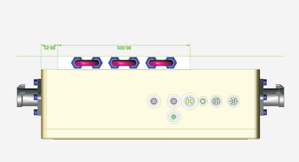


13 BAMOCAR D3 Dimensions Screw for hex key BAMOCAR
14 Block diagram BAMOCAR D3 6
15 Electrical Installation Block diagram 7
16 Connection diagram BAMOCAR D3 8
17 Electrical Installation EMC Equipments comply with the EC- regulations 00/ 08/ EG and standards EN according to the following installation and test conditions. Mounting : The equipment is conductingly mounted on a bare, aluminum plate with dimensions 500 x 500 x 5mm. mounting plate corresponds to ground plane ( vehicle ground, control panel ground ) Motor casing above 0 mm connected to ground. Equipment ground x- agnd above.5 mm connected to the mounting plate ( ground). Housing connected with mounting plate ( ground) Control connections: Signal wires are screened, analog signal wires are twisted and screened. Screen: surface contact with the mounting plate ( ground) Battery connection: 360 V DC Motor connection : Motor cables are screened, and have surface contact with the mounting plate ( ground) In case of installation in machines and equipments, the commencement of operation of the equipment in accordance with the provisions is prohibited, till it is confirmed, that the machine or equipment complies with the ec regulations 006/ / EG and the emc regulations 00/ 08/ eg, in case of vehicles ECE-Rr83, ECE-R00. A manufacturer s declaration can be requested for. 9
18 BAMOCAR D3 Connectors Connectors Connector X IN / Output a brown BTB BTB-Ready b red BTB c pink GND Auxiliary voltage 0 d yellow + Auxiliary voltage+ e gree END/LMT Limit switch f blue END/LMT Limit switch g violett FRG/RUN Enable h gray AIN+ Analog-Input j white AIN- k black GNDE Logik-GND l br-green DIN Digital-Input m br-yellow DIN Digital-Input n ws-green DOUT Digital-Output o red-blue DOUT Digital-Output p wh-yellow AIN+ Analog-Input r wh-red AIN- s wh-gray DOUT3 Digital-Output3 t wh-black RFE Rotation Enable u ws-blue +v Auxiliary voltage + Connector Binder Connector X9, X9. CAN-BUS PE (Voltage in) 3 CAN GND CAN Hh 5 CAN Ll Connector X9 Binder Connector X9. Binder Connector X 0 brown rin white txd 3 blue tou black tou 5 gray rxd 6 pink gnd RS3 Connector Binder Connector X Brake + v-br Brake + 3 Brake - GND-V-Br Connector Binder
19 Electrical Installation Feedback- connector X7 Connector Binder Connectors Connector X7 Resolver Connector X7 ENC-TTL Connector X7 SIN/COS Connector X7 bl a b c d e f g h j k l m n o p sin cos ref temp signal ref temp gnd cos sin a canal a b canal /n c canal b d voltage +5v e canal n f canal /b g canal /a h temp signal j temp gnd k rotor 3 l gnd m rotor n o rotor p a canal ka+ b canal kr+ c canal kb+ d voltage +5v e canal kr+ f canal kbg canal kah temp signal j temp gnd k canal kdl voltage gnd m canal kc+ n canal kd+ o canal kc- a mp-tacho b c tacho d voltage +5v e tacho f g tacho 3 h temp signal j temp gnd k rotor 3 l versorgung gnd m rotor n o rotor p Connector X8 Output / Input ENC-TTL a voltage +5v c selekt in e canal a g canal n j canal b l canal /b m canal /n n canal /a o voltage GND t output dac u GND dac Connector Binder At all connectors: View the plug on solder-crimp side.
 Connector plug plus Pfisterer connector straight p (35005-00..) or connector angle p (35005-0) Connector plug minus Pfisterer connector straight p (35005-00.")
20 BAMOCAR D3 Power connectors Power connectors 000V / 00A Connector socket plus Pfisterer p ( (-30)) Connector socket minus Pfisterer p ( ) Motor connector socket Pfisterer p ( ) Connector plug plus Pfisterer connector straight p ( ) or connector angle p ( ) Connector plug minus Pfisterer connector straight p ( ) or connector angle p ( ) Connector plugr motor Pfisterer connector straight p ( ) or connector angle p ( )
 only at switched main contactor K Prinzip preload Programming example Output dout switches the relay k3 when the dc link voltage ( l_o/u voltage) is higher than")
21 Electrical Installation Connection to the battery Attention: DC-Link at 00V at 700V 800mF 30mF Resistor Rv ca. 0 ohm 0w Inrush-current over k ca.0a Battery connections Enable (RUN) only at switched main contactor K Prinzip preload Programming example Output dout switches the relay k3 when the dc link voltage ( l_o/u voltage) is higher than the variable. Warning The max. supply voltage U* + 00 (700) must not be exceeded at any time (not even for short intervals)! Danger of damage! F = safety fuses Connection has no protection against reverse polarity. If the polarity of the connection is wrong, the device will be destroyed Type Connection cross-section mm AWG.KIA ) -5/ / Battery connecting line <m. For conductor lengths from to 0m more powerful. Use an additional capacity for conductor lengths superior to 0m!! 3
22 BAMOCAR D3 Auxiliary voltage Brake Auxiliary power connection Mains independent Auxiliary dc voltage V = up to V = +/- 0 % / up to A The Auxiliary voltage has - galvanic connection to logic voltage - internal self healing fuse - emc filter - external fuse only for line protection Input voltage... V DC X : GND X :3 Ripple 0 % Inrush current A Rated current in case of v. A in case of v 0.9 A Attention : For internal power supply (, A), also the sum total currents of output ( dout) has to be fed from the / V system. Attention : In case of Auxiliary voltage less than 0 V, including during short time drop outs, the internal power supply system shuts down. Temporary data in ram memory are erased. Digital rpm and torque reference are reset to 0, fault indication ( hardware fault ). Indication ok in status is off.
23 Elektrical Installation Motor power connection Use only UNITEK approved, electronically commutated synchronous motors ( brushless dc motors, ec motors) with resolver or incremental encoder. Refer Appendix A ( motor specific connection and parameter guidelines) Motor connection Connection sequence Cable indication M M M3 Motor phase U V W Connector xb: xb:3 xb: Correct wiring is essential! Motor cables, 3 wires + simply shielded protective earth conductor for 600V~, 000V=, shield capacity 50pF/m. Cable cross section minimum. Type BAMOCAR -Dx Cable dim. mm 5 35 Cable dim. AWG Motor choke. Only required upwards of a shield capacity of >5nF. approx. 5m motor cable. Magnetic rings Against HF failures of the sensor systems. Slide the rings onto the motor lines. Shielded connection: Surface connection at entry to control cabinet. Surface or as short as possible connection at the motor end. 5
24 Electrical Installation Digital inputs Opto-input Input voltage H-level (ON) +0 to +30V L-level (Off) 0 to +6V input current max. ma Ratet voltage/curen Referenc ground +V/0mA GNDE(X:0) Control Connection The enable input- (FRG/RUN) and the input for rotary field release ( RFE) are pre-fixed and cannot be programmed. Without FRG/RUN release, the servo is electronically blocked ( no pwm pulses). Without rotary field release RFE, the rotary field of the output stage is additionally blocked electronically. (second blocking channel). The drive is momentum free ( no stop-moment). The additional digital inputs are freely programmable. Inputs lmt (x: e) and lmt (x: f) are preferred and to be used as limit switch inputs. Input Plug Function Status FRG/RUN X.7 Enable fix RFE X:8 Rotation Enable fix END/LMT X:5 Limit switch /Dig. Input programmable END/LMT X:6 Limit switch /Dig. Input DIN X: Digital Input DIN X: Digital Input External power supply for inputs and outputs. +for GNDE for the logic and the auxiliary voltage Logic reference 7
25 BAMOCAR D3 Safety input RFE Safety input RFE ( rotary field release) Attention : The drive is momentum-free, in case of disabled input release or rotary field release. If there are no mechanical brakes or blocks, the drive can stop or be in motion, the motor cables are not potential-free. Only the rotary field is blocked. The servo Amplifier has to be isolated from the mains to carry out work on the motor. Operation with rfe input. Two channel release block by a safety device. Enable - input FRG/RUN plus rotary field enable input RFE Switch on Safety switch contacts closed Enable FRG/RUN 0.5 seconds after RFE. Safety shut-down. Safety switch contacts open. Absence of FRG/RUN signal -blocks the pwm pulses in the processor through the first blocking channel. Absence of FRG signal blocks the pwm pulses after the processor through the second blocking channel. Restarting : Reset safety switch Safety switch contacts closed. The motor can start rotating, only after a renewed rotary field enable, followed by enble FRG/RUN, Operation without RFE -input Input RFE has to be bridged with the logic voltage. If the logic voltage and the supply voltage are the same, bridge the RFE input with +V/ V. Enable FRG/RUN at lease 0.5 seconds after RFE signal. 8
26 Electrical Installation Digital logic- outputs ( open- emitter) Logic outputs to 3 are for laid out for / V and A. Short time A. Output voltage On-level max. +V Off-level <V Output current nom. A Output current max. A Voltage reference ground reference +V (X:) GNDE(X:0) Control signals Attention : The auxiliary voltage is also the power supply for the logical outputs. An energy saving program can be programmed. ( clocked output). Logic output ( brake V, 3 A ) is available at terminal X. Contact for max. 8V/0.A Capacitive load max. myf Contact resistance max. Ohm external fuse 0.5Aff The contact is closed when the device is eady for operation. State signal via seven-segment LED r Signal operation ready ( solid state relay) / ready BTB/RDY Operation ready are off in case of fault indications, if Auxiliary voltage is low ( <0 V) The function of indication under voltage in DC link can be programmed. BTB with or without under voltage monitoring. ( BTB-power ) Output Plug Funktion Status Parameter BTB/RDY x:a, x:b Ready fix /Relay DOUT x:n Digital output programmable DOUT x:o Digital output programmable DOUT 3 x:s Digital output 3 programmable DOUT x Digital output programmable +V for the logic and the auxiliary voltage Observe the sum of all output currents! GNDE logic ground 9
27 BAMOCAR D3 Control signals Analog inputs +/- 0V Inputs Terminal Basic function Voltage Status Parameter Ain+,Ain- X:h, X:j rpm reference value +/-0V prog. Ain+,Ain- X:p, X:r current limit +/-0V prog. Characteristics Differential input Ain+/Ain- Ain+/Ain- input impedance limit voltage resolution 70kOhm +/-V bit + sign The direction of rotation of the motor can be changed by reversing the +/- polarity at the differential input, by a logic- input or by programming. In case of digital reference value ( RS 3, x bus), analog input Ain can be programmed as external rpm limit and the Analog input Ain can be programmed as external analog current limit. Analog output +/- 0 V Output Terminal Basic function Voltage Status Parameter Aout x8:t rpm- Actual value +/-0v prog. gnd x8:u signal-gnd 0v fixed 30
28 Electrical Installation Serial interface RS3 The Amplifier BMOCAR-D3 is programmed and commissioned through the PC interface RS3. Interface The serial interface is galvanically coupled with the device - zero (GND). The software is described in the software-manual DS NDrive. Connection between the BAMOCAR-D3 ( d-connector X0 ) and the serial interface only through a null modem-cable. Do not use null modem-link cable! Cable to be plugged in only in de-energized condition. Select the interface baud rate in NDrive as 500. Null modem cable Pin assignment. Solder side. Contact shield with the plug housing. Cable length max. 0m BAMOCAR Connector X 0 RS3 Rin Txd 3 Tou Dtr 5 Rxd 3
29 BAMOCAR D3 Interface CAN-BUS The CAN-BUS is a digital connection to the CNC control. Optimum conditions are achieved with CNC controls and CAN components of LABOD electronic or CAN Open. Programming and operation by means of the control panel via the CAN-BUS. Interface complies with the standard ISO 898. Adjustment and programming see Manual DS-CAN The CAN-BUS input is galvanically separated. The power supply is from the intern DC/DC. CAN-BUS cable Use a shielded bus conductor with a low shielding capacity. Signal plus GND (+supply). D-connector with a metal or metallized housing. LiYCY x0.5+shield. Designation Connector no. X9, X9. CAN-BUS Cable colour Sield green-white CAN-v+ brown CAN-gnd 3 white CAN-h green CAN-l 5 yellow x9. Female x9 Male Pin assignment. Solder side Terminating resistor at the end of the bus line > 0Ohm between the CAN-H and CAN-L CAN-BUS connection with several BAMOCAR-D3 Master Address xx Address xx Address xn PE on the housing Terminating resistor at the end of the bus line > 0Ohm between the CAN-H and CAN-L 3
30 Elektrical Installation Resolver - connection. Applicable only for BAMOCAR D3 xx-rs The resolver is an absolute measuring system for motor rotation. It is robust and insensitive against high motor temperatures. The construction is similar to a rotating transformer. The rotor is fed from the reference ( 0 khz) The stator delivers the sine and cosine - signals, that are modulated from the rotational frequency. The Amplitudes of these signals will be evaluated and digitized in the servo Amplifier. The resolution will be optimally set to 0, or bits automatically. The maximum possible rpm is ( 0 bit) The digitized signals are used for the polar wheel Angle, position and speed control and for incremental outputs. Resolver Connector X7 Resolver A b c d e f g h j k l m n o p sin cos ref temperature signal ref temperature gnd cos sin Use only UNITEK approved motors (Appendix A)with,, 6 or 8 pole resolver Follow motor specific connection chart ( RS) Connector x7 : 9 pole round connector Connecting cable : x core twisted pair and screened, plus total shield. In case of drag chain use only suitable cable. Cable length: In case of length > 5 m, use only high quality resolver cable with better screen properties. Screen connection At connector x7, connect all screens together with the casing. At the motor connector, connect the total shield with the connector housing. Individual parameter refer software manual DS NDrive. 33
31 BAMOCAR D3 Encoder TTL Encoder TTL Anschluß only BAMOCAR-D3-IN TTL encoder with counter channels and one zero channel plus 3 rotor position channels. Counters with or without push-pull output. In case of simple connection a, b, n, do not use the negated inputs. Counter input complies with rs 85 maximum counter frequency 500 khz. The encoder is galvanically connected to the equipment earth ( GND). Supply voltage is fed by the servo. Connector X7 ENC-TTL a canal a b canal /n c canal b d voltage +5v e canal n f canal /b g canal /a h temp signal j temp gnd k rotor 3 l gnd m rotor n o rotor p To be used only with UNITEK approved motors ( Appendix A) with ttl encoder and rotor position tracks. observe motor specific connection chart ( IN ). Connector: X7 9 pole round connector Connecting cable : 0 signal wires screened, minimum cross section 0.mm power supply wires, minimum cross section 0.5mm In case of drag chain, use only suitable cables. Cable length : one level more in case of cross section greater than 5m. Screen connection : At connector X7, connect screen with connector casing Individual parameter refer software manual DS NDrive. 3
32 Electrical Installation SIN / COS Vss Anschluss only BAMOCAR-D3-xx-SC SIN COS Vss connection only in case of BAMOCAR-D3 xx-sc Encoder with analog sinusoidal counter track and a track zero plus two commutation tracks. Differential signals Vss signal difference Maximum counter frequency 500 khz. The encoder is galvanically connected to equipment ground ( GND). Servo feeds the supply voltage 5V SIN/COS vss Optimum resolution will be automatically selected. Connector X7 SIN/COS a canal ka+ b canal kr+ c canal kb+ d voltage +5v e canal kr+ f canal kbg canal kah temp signal j temp gnd k canal kdl voltage gnd m canal kc+ n canal kd+ o canal kc- Use only UNITEK approved motors ( Appendix A ) with sin/ cos sensor ( SC). observe motor specific connection chart ( SC) Connection terminal X 7 Connecting cable Cable type : 9 pole round connector x core signal cable, drill screened Minimum cross section 0.mm core signal screened cable minimum cross section 0. mm core power supply cables, temperature minimum cross section 0.5 mm (x(x0.)+(x0.)c+x0.5)c Use appropriate cable in case of drag chain. in case of length > 5m, cross section one step higher. At connector X 7 connect screen with the connector Cable length Screen connection casing. At motor connector connect screen with connector casing. Individual parameter refer software manual DS NDrive. 35
33 BAMOCAR D3 Rotor sensor Rotor sensor Anschluss with bl-tacho only BAMOCAR-D3- xx-bl Rotor position indicator connection with bl-tacho only in case of BAMOCAR-D3 xx-bl 3 rotor position sensor signals ( hall sensors) for commutation. With or without brushless tacho generator. The rotor position sensor is galvanically connected with the equipment ground ( gnd). Supply voltage 5 v is from servo. Adapter, when tacho voltage at nominal rpm is more than 0 volts. In case of low tacho-voltages connect x7: pin,9 and. Connect the centre point of the tacho with x7: Connector X7 bl a mp-tacho b c tacho d voltage +5v e tacho f g tacho 3 h temp signal j temp gnd k rotor 3 l versorgung gnd m rotor n o rotor p To be used only with motors approved by UNITEK ( Appendix A) with rotor position sensor (bl). Observe the motor-specific connection chart ( bl). Terminal connector X7 Connecting cable Cable length 9 pole round connector x signal cables, supply cables, temp Minimum cross-section 0.5 mm In case of pull chain use only suitable cable. In case of > 5 m diameter, one step more. Screen connection At connector x 7, connect screen with the connector casing. Connect the screen with the connector casing at the motor connector end. Individual parameters refer software manual DS NDrive. 36
34 Electrical Installation X8 TTL- Encoder output or input ( ) The D- connector X8 will be operated as input or output( default). Output X8 pin c not used or connected with GND. Input X8 pin c connected with + 5 v ( x8: a) X8 Encoder - output - input Connector X8 Output / Input ENC-TTL a voltage +5v c selekt in e canal a g canal n j j canal b l l canal /b m canal /n n canal /a o voltage GND t output dac Attention X8 as input Connect x8: C ( select in ) with x8:a ( + 5 V) within the connector. 37
35 FreeSB FSB-PR-0 Power Relay Management Features Manages up to 3 independent power outputs (DC coil contactor, fans ) Supports wide DC contactor coil voltage levels ( ranges depending of supply reference: from 9V to 36V or from 8V to 75V) Supports wide input voltage levels from 0V to 75V Current measurement through external Hall effect current sensor Isolated CAN bus interface to adjacent devices Compliant with FreeSafe (Freemens Battery Management System) for complete battery management solution Non isolated I²C communication Contactor and fuse continuity tester Built-in self-tests High EMI immunity Applications Electric and Hybrid Electric Vehicles High Power Portable Equipments Backup Battery Systems Electric Bicycles, Motorcycles, Scooters Description FreeSB-PR is a smart circuit breaker especially designed for high currents. FreeSB-PR can drive up to 3 external devices such as power switches or fans, powered by the supply dedicated to the circuit breaker (e.g. it is possible to wire two contactors and one light). FreeSB-PR provides an easy to use solution to manage large packs of Li-Ion batteries. FreeSB-PR boards are easy and safe to connect or disconnect. FreeSB-PR supports a wide voltage supply range in order to drive a large range of DC contactor coils. Current measurement is assured using external Hall effect sensor that must have a current output for the measurement. The accuracy of the measurements depends on the accuracy of the sensor. A ± V power supply is available for the sensor. FreeSB-PR cuts off the current when a short circuit is detected: the cut off time depends on the switch off time of the power switch. FreeSB-PR can also react on overcurrent or over-temperature: these parameters are programmable as well as the time to react. FreeSB-PR protects the battery cells from over and under voltage based on the data received from FreeSafe Battery Management System. The circuit breaker is continuously testing the fuse and power switch in order to assure the integrity of these devices. To ensure that the battery is used properly, FreeSB-PR sends all the data to FreeSafe, which records all activities in an up to 0 years long data history file. The communication between FreeSafe and FreeSB-PR is realized through CAN bus. FreeSB-PR is delivered with a comprehensive CAN application layer. While FreeSB-PR devices are plug and play" for LFP batteries, specific applications and other chemistries require custom settings. FreeSB-PR parameters can be easily changed. v.00


36 FreeSB-PR Typical Application Figure - FSB-PR board inputs and outputs Figure - Example of a battery management solution with 3 stacked FreeSafe boards, a FreeSB-PR and its peripherals v.00
37 FreeSB-PR Absolute Maximum Ratings Parameter Symbol Value Units Maximum input supply voltage Vin 36 or 75 * V Maximum DC contactor coil voltage Maximum allowed inrush current per power output 5 A Maximum input current measurement provided by a Hall Effect ±0 ma sensor Operating temperature range -0 to 85 C Maximum CANbus supply current 00 ma Maximum voltage for isolated continuity testers 00 V * Input voltage is either 9-36V or 8-75V according to the supply reference onboard. General description The following functional blocs are presented: Figure 3 - Functional diagram Management (processor) Sensors & Drivers Power Supply Communication 3 v.00
38 FreeSB-PR Power supply unit FreeSB-PR integrates its own Power Supply Unit (PSU) making the board fully standalone once connected to a wide range of DC sources. On board supplies are isolated ±V DC, 5V DC and 3.3V DC. By default, the PSU must be connected to a source with a voltage range between 8V and 75V. FreeSB-PR can also accept an input between 9V and 36V, if the reference of the PSU is adapted. DC source design choices The DC source of FSB-PR must provide any voltage between 8V and 75V (or 9V and 36V). At least 6Wmax are needed to supply all the electronics on the board. The DC source must also provide enough current to be able to withstand the inrush current when driving DC contactor coils. The standard solution is a DC/DC converter directly plugged on the battery and designed to provide enough power. Another solution could be to plug FSB-PR directly to the main battery if the voltage concurs with the input limits. It is possible to use an intermediate point on the main battery as a DC source - for instance connecting FSB-PR between the ground and the 8 th cell of a 5 cells 8V LiFePO battery provides a 0V to 9.V supply. But this will unbalance the firsts 8 cells of the pack and an equalizer such as a FreeFlex (Freemens Flexible Power Supply) will be required. There is another constraint in the choice of the DC source: the driving voltage of the DC contactor coil. The supply voltage will be directly reused to drive the contactor, so all the devices must work with the same voltage level (source, contactor, fans, lamp, etc). Connecting FSB-PR to the DC source The DC source must ensure a stable input voltage in the specified input range. For that the connection between FSB- PR and its source must be carefully considered. If the DC source is the battery or a DC/DC converter (isolated or not) whose input is the battery, the connection to FSB-PR has to be a star connection as shown on the next figure. This star connection guarantees that the power current flowing to the application, or from the charger, will not trouble the input of FSP-PR from wire inductive or resistive perturbation. v.00
39 FreeSB-PR Using the battery as the DC source for FSPB-PR-0: Direct use if 9V<Vbat<75V Through a DC/DC converter Figure Connection of the DC source to FSB-PR Sensors & Drivers The Sensors & Drivers block provides precise and reliable measurements related to the operating conditions. As a result, FreeSB-PR is able to sense power current and drives up to 3 independent power outputs. Current measurement is retrieved through an analog to digital conversion of the measurement given by a Hall Effect sensor device. In addition, FreeSB-PR includes sensors that measure the insulation resistor between the chassis and the battery contacts and also continuity testers that detect a fuse or power contactor fault. Hall Effect sensor design choices Two constraints guide the choice of a Hall Effect sensor working with FSB-PR. The first one is that the supply voltage provided by the board is a ±V dual supply (±50mA max). The second one is that the sensor must be a current transducer that will provide an output current measurement, which is an image of the power current. This current measurement must be ±0mA max, otherwise, the measure will exceed the full scale measurement because of the default amplification gain on FSB-PR. v.00 5
40 FreeSB-PR The gain of the Hall Effect sensor can be configured through the configuration file of FreeSafe. To modify the gain of the FSB-PR board in order to change the limit of the full-scale measurement a custom PCB design will be needed. Example of recommended Hall Effect sensors: - LEM LS 05-S/SP3: ±00A nominal current measurement, ±V supply, closed loop current transducer (:000 ratio). Datasheet: - Tamura S3P50/00D5M with similar characteristics. Datasheet: Contactor (or fan or other peripheral) design choices The power DC contactor as shown in Figure 5, must be designed to withstand the battery voltage, the nominal power current and to be able to cut over current or even, if needed, short-circuit current. The driving voltage of the coil and the supply voltage of the board must be the same. The maximum inrush current that drives the coil must be less than 5A during 00ms and the maximum continuous driving current must be less than 3.75A if only one output is supplying the current and.a per output if all three outputs are working in the same time. Following these recommendations ensure the proper use of FSB-PR and its functions. Figure 5 - functional diagram of the 3 DC power outputs and their supply Example of recommended DC contactor: - TE connectivity Kilovac EV00: 900Vdc max, 500Amax, 9V to 95V coil voltage. Datasheet: Management A powerful 6bits DSC (Digital Signal Controller) is used for the data processing. The DSC is the core of the system where most of the algorithms are implemented. It communicates and controls the other function of the BMS: Driving the 3 power outputs to change the states of the contactors, fans, etc. Measurements retrieval from all the sensors Estimators computing Wired system level communications FreeSB-PR transmits its data (e.g. current measurement or events) to FreeSafe through CAN communications. All data related to the battery and the BMS operations are then stored and kept available for future use. Based on an embedded micro SD card of Gbits (default configuration), FreeSafe is able to record up to 0 years of data. Remote access is possible for the battery fleet control & monitoring thought proprietary FreeLab application and FreeData database. v.00 6
41 FreeSB-PR Communication FSB-PR includes hardware for CAN bus communication protocols to facilitate the communication between the BMS and the other control or power interfaces of the system. In particular, FreeSB-PR integrates an isolated CAN Bus allowing to communicate with other Freemens products (the FreeSafe solutions for instance). For the communication with other external devices, a second CAN bus is provided but this feature needs a custom development to implement the desired communication protocol. The extensive communication techniques allow FreeSB-PR to receive control orders, updated programs and parameters. v.00 7

42 FreeSB-PR Connectors Configuration Two variants of the connectors configuration of FSB-PR are possible. The first one is a version with wire-to-board connector and is designed for general use. The alternate version has board-to-board connectors and is designed to be plugged on a mother board. Between the two variants, all the connectors have the same pins configurations, the difference is based on the footprint and the mechanical characteristics of the connectors. Wire-to-board version Figure 6 - FreeSB-PR top side view Connectors description Connector Description I²C / GPIO connector CAN bus n. Main CAN connected to FreeSafe Boards 3 CAN bus n. Secondary CAN for custom protocols Connector for Hall sensor, continuity tester, insulation measurement 5 Input supply and output to contactors or fans 6 Programming connector Connectors references Onboard connector Recommended complementary connector N Manufacturer Reference Manufacturer Reference, & 3 Harting Harting M 3365/06 Molex Molex Molex Molex Molex Molex v.00


43 FreeSB-PR Connector n - I²C / GPIO Pins Description Over Voltage signal SDA 3 Digital I/O SCL 5 Analog or digital I/O 6 NC Connector n & n 3 CAN BUS Pins Description 5V output up to 00 ma 3 CAN L CAN H 5 6 GND Connector n Sensors inputs & outputs Pins Description -V output up to -50 ma IM Input measurement for Hall Effect sensor 3 Fn Continuity testing input +V output up to 50 ma 5 Cp Continuity testing input 6 Chassis 7 Cn Continuity testing input 8 Fp Continuity testing input 9 Bat+ Continuity testing input 0 Bat- Continuity testing input Connector n 5 Power inputs & outputs Pins Description Power output negative C3- Power output positive - C3+ 3 Power output negative - C- Power output positive - C+ 5 Power output negative- C- 6 Power output positive - C+ 7 GNDsource 8 Vsource Connector n 6 Programming connector Pins Description Reset 3.3V 3 GND PGD 5 PDC 9 v.00

44 FreeSB-PR Alternative connector version In this FreeSB-PR version, all connectors are replaced with standard pitch.00" (.5mm) terminal strips enabling simple board-to-board interfacing. The pin configuration between the different versions is identical. Figure 7 - FSB-PR alternate connector version. Bottom view. Onboard connector Recommended complementary connector N Manufacturer Part number Manufacturer Part number, & 3 SAMTEC TSW T-D SAMTEC SSW T-D SAMTEC TSW T-D SAMTEC SSW T-D 5 SAMTEC TSW-0-07-T-D SAMTEC SSW-0-07-T-D 6 SAMTEC TSW T-S SAMTEC SSW T-S Connection procedure Step Connector Comment,, 3 & No particular steps are required for these connectors. FreeSB-PR will not start or power up before the power connector (n 5) is connected to the supply. 5 second after the connection, the initialization routine will close the main power contactor if no fault is detected. Caution 6 Programming connector is only used when firmware update is necessary. Notice that pin 3 is referenced to the chassis terminal of the th connector. Caution must be taken when connecting a non-isolated debugger or programmer v.00 0
45 Connection to the battery management system FreeSB-PR Figure 8 - A typical application for a 30 cells LiFePO battery (96V), V DC contactors (power and auxiliary), warning light and on/off switch v.00
46 FreeSB-PR Electrical Characteristics The following specifications apply to the full operating temperature range Supply Parameter Symbol Conditions Min Typ Max Units Input Voltage V in 0 75 V Supply Current I s Sleep Mode (Vin = 0 V) 9 ma Normal Mode (Vin = 0 V) 9, ma Sleep Mode (Vin = 75 V) 6,5 ma Normal Mode (Vin = 75 V) ma More details on the current consumption are shown on Figure 9 below. Temperature max on the board: 35 C. The ambient temperature is 5 C. Figure 9 - Supply current vs input voltage DC power output (for driving contactor, fan or other dc peripherals) Parameter Symbol Conditions Min Typ Max Units Output Voltage V out V out=v in 0 75 V Max peak current per I outmax Non repetitive t peak=00ms 5 A output Max continuous current per I out Only one output T amb 3.75 A output working =5 C All three outputs are working. A v.00
47 FreeSB-PR CANBUS (main and custom secondary) Parameter Symbol Conditions Min Typ Max Units Supply Voltage (Bus side) V bus Power on the bus is provided by the first BMS of the string 5 V Can Bus Output Voltage CAN H V Vi = 0 V, R L=60 Ohm (dominant) CAN L V Can Bus Output Voltage.3 3 V Vi = V, R L=60 Ohm (recessive) Can Bus High-level output I OH Driver -70 ma current Receiver - ma Can Bus Low-level output I OL Driver 70 ma current Receiver ma Can Bus Rate of Operation F can Mbps I²C / GPIO (not isolated) Parameter Symbol Conditions Min Typ Max Units Max input / output voltage V Min input / output voltage 3 0 V 3 inputs or outputs in 3.3V logic. Hall Effect sensor Parameter Symbol Conditions Min Typ Max Units Supply voltage V hall Dual voltage supply ±.6 ± ±. V Voltage ripple 0mV Max supply current Current consumption of Hall ±50 ma Effect sensor on ±V supply Max input current on FSB- I hall Mandatory use of a current ±0 ma PR transducer Hall effect sensor Internal ADC precision 5 Output current of Hall sensor converted by a bits ADC 0.05 ma the ±V supply is short-circuit protected. 5 the resolution of the conversion of the output current provided by the Hall Effect sensor. The 0mA max converted by a bits ADC gives 0/ =0.05mA/bit. v.00 3
48 FreeSB-PR Operation Standard peripherals The use of FreeSB-PR requires the following devices: - A configured FreeSafe system. - A main contactor to allow or not the use of the battery. Connected on C+ & C- of connector n 5. - A Hall Effect Sensor to measure the power current, to protect the battery and its application and to estimate some state indicators such as the State Of Charge (SOC) or the State Of Health (SOH) of the battery. Connected on ±V & Im on connector n. - Optional elements, such as an auxiliary contactor (connected on C+ & C- of connector n 5) to drive the external battery charger or a lamp indicator (connected on C3+ & C3- of the 5 th connector) which is lighted when the SOC is less than 0%, are already provided in the standard operating version. If other functions are needed - e.g. fan driving or other operating logic for the contactors (power or auxiliary) - a custom firmware design will be necessary. The behavior of the peripherals on C and C3 output can easily be configured upon request before the firmware is loaded in the FSB-PR board. Further ongoing development will allow a fast configuration and reconfiguration through parameters stored on the memory card of FreeSafe without having to reload a new firmware. Switches can be wired on FreeSafe to ensure some additional functionalities. The description of these functions are described in the FreeSafe datasheet and are resumed below. - A switch to control the state of the main power contactor, the shutdown state and to re-engage the system when it enters in protection mode after a fault detection. The faults management is described in the section p Fault management process. It is connected on the connector n 5 of FS-0M, between pins and 3 (or between pin and GND) - An optional switch dedicated to the wake up function if needed by the application (example: the connection of a charger wakes the system up through the use of this function). First connection After its first connection to the main elements of the system (cf previous paragraph), the system starts if it is supplied. If no fault is detected - proper communication with the rest of the system, no over or under voltage or no over or under temperature of the battery - and if the main switch enable its operation, the main power contactor is driven and its contacts are closed to allow the use of the battery. Depending on the battery state (SOC<00% and no over voltage detected), the auxiliary contactor (if connected) is closed to allow a charge by the external charger. The lamp (if connected) is lighted as soon as the SOC falls under 0%. 0% is the default threshold, any over value can be configured before loading the firmware. Tuning of the Hall Effect current sensor The configuration file in the memory card of FreeSafe contains a few parameters enabling the current measurement: - Id 9, CURRENT_MEAS_CONVENTION), enables the change of the convention sign of the current measurement. The convention for the current measurement of FSB-PR is to count positively the current that charge the battery and negatively the current that discharge the battery. v.00
49 FreeSB-PR - Id 38, FSB_PR_LEM_GAIN, settles the gain of the chosen current sensor. For instance, with the LF 05-S/SP3 from LEM, FSB_PR_LEM_GAIN = Id 5, FSB_PR_REF_CURRENT, is the parameter that sets the value of the current reference to ensure that the measurement of a zero current value is truly on the 0A operating point. The need of adjustment of the current measurement can be required in two cases. First, the sign of the current measurement does not match to the convention that the current charging the battery has to be positive. Second, the current measurement is not 0A when the power contactor is opened and must be adjusted. In the first case, there are two solution: the current sensor can be re-wired in the other direction to be rotated by 80, or the parameter CURRENT_MEAS_CONVENTION in the configuration file can be modified to fit the convention. For the second case, the parameter FSB_PR_REF_CURRENT will be used to settle the internal reference of FSB-PR to get the right zero current measurement. The following method has to be applied: - Ensure that no current is flowing in the battery through the current sensor - Read the value of the current measured Imes (average value on a few seconds) - Modify the parameter FSB_PR_REF_CURRENT in the configuration file according to the formula bellow Imes 868 FSB_PR_REF_CURRENT (new value) = FSB_PR_REF_CURRENT (previous value) + FSB_PR_LEM_GAIN - Reset FreeSafe to force the loading of the new value - Check the modification by reading the new value of the 0A. N.B. : after the modification of one or several parameters in the configuration file, a reset of FreeSafe is mandatory to insure that the new parameters are loaded. N.B. : very low current values, under % of the nominal current, can be subject to noise perturbations and are not measured. The battery is then ready to be used in its standard operation. Standard operation After the first connection, if no action on the battery (current consumption for example) is detected during 60 seconds, FreeSB-PR enters in a standby mode and the 3 power outputs are turned OFF to save energy. To exit the standby mode, the wake up switch or the main switch must be activated. It is also possible to activate the main switch to wake the system up and to turn the main contactor ON again. When the battery is ready to be used, any current can be applied to charge or discharge it. Every 00ms, the state of the battery (including current measurement, coulomb counting and fault detection) is transmitted and updated between FreeSafe and FreeSB-PR via CAN communication. The main switch has three functions. The first one is to change the state of the main power contactor (closed or opened). The second one affects the default mode and allows the user to restart the contactor after a fault management. This function is described in the section Fault management process below. The last function is to wake up the system or allow its shutdown. v.00 5
50 FreeSB-PR Fault management process Whenever a fault is detected (e.g over current or communication error), the standard fault management is started. The main power contactor is opened to protect the battery and its application. A manual action from the user - to acknowledge the fault detection, to find the error and if needed, to repair it - will be requested via the main control switch to allow FreeSB-PR to resume its operation. There are three fault managements that are not included in this process: the short circuit, the under voltage and the communication faults. They are described in the next paragraphs. Short circuit (i.e. hard current limit) management Among the configuration parameters available in FreeSafe, a pair sets the positive and negative hard current limit ( CURRENT_PIC and CURRENT_PIC_NEG ). Beyond these limits, FreeSB-PR instantaneously opens the main DC contactor to protect the system. The time response of this protection depends on two elements: the response time of the current sensor chain and the response time of the contactor. - Response time of the Hall Effect sensor. If the selected device has similar characteristics to the ones proposed in the Sensors and drivers section, it will be <0µs they have a measurement bandwidth of 00 khz. - Response time of the analog to digital conversion and processor decision management. It will be less than 00µs as the whole process is calibrated to work at 0 khz. - Response time of the power DC contactor. If the selected device has similar characteristics to the one proposed in the Sensors and drivers section, it will be less than ms. After detecting a short circuit and opening the power DC contactor, FreeSB-PR waits for the reboot switch to be activated in order to re-engage the power contactor and resume its operation. Under voltage management Like any over error, the standard fault management is applied. Normally, after a voltage fault the voltage returns to the standard values: for an overvoltage, as soon as the current stops, the cells voltages decrease and stabilize to a value under the overvoltage limit. The same applies for the under voltage limit, as soon as the current stops, the cells voltages rise and stabilize to a value higher than the under voltage limit. When there are devices that cannot be disconnected by the main power contactor (for instance any critical device which must not be shut down like the battery management system or an emergency power supply), a problem with the under voltage management appears. Even if the main power contactor is opened, there is still some current that can be drawn and keep the battery cells under the voltage limit. The main contactor cannot be closed automatically and so it will not be possible to charge the battery without an external action from the user: the switch must be used to force the circuit closure. The contactor will be opened 60 seconds later if no charge current is measured. Any discharge current detected during this forced closure will lead to an immediate opening of the contactor to protect the battery. Communication error management If a communication error is detected, a retry is attempted 5 times, each 0ms. One second later, if FreeSB-PR still cannot exchange any information with FreeSafe, it will assume a communication fault and to protect the system will open the main power contactor until the communication is reestablished. v.00 6
51 FreeSB-PR Over current (i.e. soft current limit) management There are 3 configurable parameters: CURRENT_LIMIT, CURRENT_TIME and CURRENT_NOMINAL for positive current and CURRENT_LIMIT_NEG, CURRENT_TIME_NEG and CURRENT_NOMINAL_NEG for negative current. CURRENT_NOMINAL is used to define the nominal current at which the system is designed to be used (i.e thermally stable). It can be the nominal current of the battery itself or the nominal current of its application. CURRENT_TIME defines the allowed time of an overcurrent that exceeds the CURRENT_LIMIT value. See chapter Features being developed for next firmware release for more details about the overcurrent management in the next firmware release. Configuration Thanks to the configuration file hosted on FreeSafe and its communication via CAN BUS, various software elements of FreeSB-PR can be configured. Among all the available parameters, the following list gives and briefly describes the ones related to FreeSB-PR configuration. The complete list of the parameters with their full description is available in the FreeSafe datasheet (section configuration, table 3 in page 0 in the FreeSafe datasheet). v.00 7

 of FSB-PR. Board-to-board connector version.")
52 FreeSB-PR Mechanical Characteristics This section presents the mechanical data of the two connector variants of FreeSB-PR: the wire-to-board connectors and the standard board-to-board. 00 pitch connector. Figure 0 - Mechanical views (top and side views) of FSB-PR. Wire-to-board connector version. All dimensions are in mm. Figure -Mechanical view (side view) of FSB-PR. Board-to-board connector version. All dimensions are in mm. v.00 8
.")
53 FreeSB-PR Wire-to-board version Board-to-board version Figure -Coordinates of the pin n of each connector for the two connectors variants. All dimensions are in mm. The coordinates of the pins n of each connector are the same for the two FSB-PR variants (wire-to-board and boardto-board). The differences occur on the pitch of the connectors: for connectors n & 5 (power inputs & outputs and sensors & drivers) the pitch is 3mm for the wire-to-board version or.5mm for the board-to-board version. v.00 9
54 FreeSB-PR Features being developed for the next firmware release Fuse and contactor continuity tester The continuity testers available in FSB-PR are specially designed to detect a continuity break on the positive or negative power line of the battery. To use the continuity testers, some potentials must be wired to the system and are limited to the two power lines of the battery. In fact, the continuity between the Bat+ and Fp, Bat+ and Cp for the positive power line is tested. For the negative power line, the continuity between Bat- and Fn, Bat- and Cn is tested. Figure 3 shows a typical application with fuse and contactor protection on each power line. Figure 3 - Wiring (in grey lines) to test the fuse and contactor continuity with FSB-PR As shown on Figure 3, there is a priority in the continuity of the tests. If the first element (tested between Bat+ and Fp) is opening the circuit, the second (tested between Bat+ and Cp) will be seen as opened even if it is closed. The table below summarizes these events. D_Fp is the logic output of the continuity tester on Fp (0 means no discontinuity detected, means discontinuity detected), D_Cp for Cp, etc. D_Fp D_Cp Positive fuse Positive contactor state State 0 0 ON ON 0 ON OFF X OFF X D_Fn D_Cn Negative fuse Negative contactor state State 0 0 ON ON 0 ON OFF X OFF X Standard operation of continuity testing Each time after driving the main power contactor to close, a continuity test is performed. If a continuity fault is detected, it is transferred to FreeSafe, saved in its memory and the standard fault management is engaged. In order to configure the continuity tester inside the FSB-PR software, there is a variable in the configuration file of FreeSafe: CONTINUITY_TEST. It is a bits variable where each bit corresponds to a continuity test on Fp, Cp, Fn or Cn. 0 means the test is disabled and means the test is enabled. v.00 0
55 FreeSB-PR CONTINUITY_TEST Bit 0 Bit Bit Bit 3 Enable test on Fp Cp Fn Cn To disable the continuity test functions, it is recommended to set CONTINUITY_TEST=0000 and not to connect Bat+, Bat-, Fp, Cp, Fn and Cn. N.B: if the insulation measurement function is used, Bat+ and Bat- MUST be connected. Over current (i.e. soft current limit) management There are 3 configurable parameters: CURRENT_LIMIT, CURRENT_TIME and CURRENT_NOMINAL for positive current and CURRENT_LIMIT_NEG, CURRENT_TIME_NEG and CURRENT_NOMINAL_NEG for negative current. CURRENT_NOMINAL is used to define the nominal current at which the system is designed to be used (i.e thermally stable). It can be the nominal current of the battery itself or the nominal current of its application. CURENT_LIMIT defines an authorized pulse of constant current over the nominal current for a set CURRENT_TIME time. To facilitate the writing of the used equation, the parameters are named in this document as following: I nom is the nominal current ( CURRENT_NOMINAL parameter) I oc is the overcurrent limit ( CURRENT_LIMIT parameter) t oc is the overcurrent allowed time ( CURRENT_TIME parameter) Isc is the short circuit limit ( CURRENT_PIC parameter) The management of overcurrent follows an I²t logic. The parameters given in the initial configuration are used to set the reference: (I oc I nom )² t oc, and then for any continuous current, it is possible to determine the maximum allowed time with (I(t) I nom )² t = (I oc I nom )² t oc. The next paragraph and Figure show an example in order to support the comprehension. For non-constant current, the I²t logic is still followed thanks to the implemented integral method. It consists on the comparison between the reference I oc²t oc and the integration of the measured current over time. Example of hard and soft current limit management We define a battery with I nom=00a, I oc=50a, t oc=0s and the hard current limit I sc=00a for its discharge characteristics. With only these parameters, FreeSB-PR can manage the overcurrent according to the explained method. For any constant current, the behavior of FreeSB-PR is resumed on the following curves Figure. - Any current below the nominal current can operate for an infinite time the safe operating area under the blue line in Figure. - Any current between I nom and I oc can be maintained for a short amount of time the overcurrent management area between the blue and red lines in Figure Erreur! Source du renvoi introuvable.. For instance a 0A current (0% over the nominal) is allowed for 50s while a 75A current (75% over the nominal) is allowed for only.5s. This red curve is defined from I nom, I oc and t oc parameters: I(t) = (I oc I nom )² t oc I t nom - comes from : (I(t) I nom )² t = (I oc I nom )² t oc v.00

56 FreeSB-PR - Any current over the hard current limit (00A) is in the protected area where the power DC contactor is opened. Figure - Example of overcurrent management curves for constant current v.00

57 Introducing KILOVAC LEV00 Series 900 Vdc Contactor with form X contacts rated 00A continuous
58 KILOVAC LEV00 Series 900 Vdc Contactor PART NUMBERING Typical Part Number LEV00 A A N G Series: LEV00 = 00A Contactor Contact Arrangement: A = Form X (SPST-NO-DM) Coil Voltage: = VDC 5 = VDC 6 = 8VDC Coil Wire Length: A = 5 inches [.M] Coil Termination: N = None Stripped Wires Mounting and Power Terminals: G = Bottom Mount ( x #8); M5 x 0 H = Side Mount ( x #8); M5 x 0 NOTE: All part numbers are RoHS compliant. Specifications are subject to change without notice. PRODUCT OFFERING Bottom Mount Models LEV00AANG Vdc coil 5 [.m] leads LEV00A5ANG Vdc coil 5 [.m] leads LEV00A6ANG 8Vdc coil 5 [.m] leads Side Mount Models LEV00AANH Vdc coil 5 [.m] leads LEV00A5ANH Vdc coil 5 [.m] leads LEV00A6ANH 8Vdc coil 5 [.m] leads Tyco Electronics I LEV00
![KILOVAC LEV00 Series 900 Vdc Contactor PERFORMANCE DATA Bottom Mount.8 [ 6.3 ].70 [ 7.78 ] MOUNTING HARDWARE (NOT SUPPLIED): X M BOLT, LOCKWASHER AND WASHER TORQUE: 0 IN-LBS MAX [.](/docs-images/74/70249235/images/59-0.jpg "3 NM MAX].56 DIA. [ 39.5 ] M5 FEMALE LOAD TERMINALS - PLACES HARDWARE (NOT SUPPLIED) X M5 BOLT, LOCKWASHER AND WASHER TORQUE: 30 TO 0 IN-LBS [3. TO.5 NM].8 [ 57.96 ].07 [ 5.5 ].30 [7.")
![6 ] Side Mount.8 [ 6.3 ].8 [57.96 ].99 [ 5.0 ].07 [ 5.5 ] MOUNTING HARDWARE (NOT SUPPLIED): X M BOLT, LOCKWASHER AND WASHER TORQUE: 0 IN-LBS MAX [.3 NM MAX].70 [7.78 ].6 [ 0.77 ].](/docs-images/74/70249235/images/59-1.jpg "56 DIA. [ 39.5 ] M5 FEMALE LOAD TERMINALS - PLACES HARDWARE (NOT SUPPLIED) X M5 BOLT, LOCKWASHER AND WASHER TORQUE: 30 TO 0 IN-LBS [3. TO.5 NM].83 [.0 ].30 [7.")
59 KILOVAC LEV00 Series 900 Vdc Contactor PERFORMANCE DATA Bottom Mount.8 [ 6.3 ].70 [ 7.78 ] MOUNTING HARDWARE (NOT SUPPLIED): X M BOLT, LOCKWASHER AND WASHER TORQUE: 0 IN-LBS MAX [.3 NM MAX].56 DIA. [ 39.5 ] M5 FEMALE LOAD TERMINALS - PLACES HARDWARE (NOT SUPPLIED) X M5 BOLT, LOCKWASHER AND WASHER TORQUE: 30 TO 0 IN-LBS [3. TO.5 NM].8 [ ].07 [ 5.5 ].30 [7.6 ] Side Mount.8 [ 6.3 ].8 [57.96 ].99 [ 5.0 ].07 [ 5.5 ] MOUNTING HARDWARE (NOT SUPPLIED): X M BOLT, LOCKWASHER AND WASHER TORQUE: 0 IN-LBS MAX [.3 NM MAX].70 [7.78 ].6 [ 0.77 ].56 DIA. [ 39.5 ] M5 FEMALE LOAD TERMINALS - PLACES HARDWARE (NOT SUPPLIED) X M5 BOLT, LOCKWASHER AND WASHER TORQUE: 30 TO 0 IN-LBS [3. TO.5 NM].83 [.0 ].30 [7.6 ] LEV00 I Tyco Electronics
60 KILOVAC LEV00 Series 900 Vdc Contactor KEY FEATURES Hermetically sealed intrinsically safe. Operates in explosive/harsh environments without oxidation or contamination of contacts, including long periods of non-operation 8kV isolation between open contacts permits use for high voltage isolation and carry, and 8 Vdc coils Designed and built in accordance to AIAG QS9000 DESCRIPTION Lowest cost, 900 Vdc 00 amp, hermetically sealed DC contactor in the industry Compact package available in side- or bottom-mount configurations, not position sensitive APPLICATIONS Power/motor control circuit isolation, circuit protection and safety in industrial machinery Automotive battery switching and backup MECHANICAL Compact epoxy-sealed resin enclosure occupies only about in 3 (65.5 cm 3 ) Robust integral mounting plate on either bottom or side of enclosure accepts two M screws Inert gas filled contact chamber Flying leads for coil connections Load terminals threaded for M5 bolts (not included) LOAD LIFE VS. RESISTIVE POWER SWITCHING RoHS Ready Tyco Electronics I LEV00
61 KILOVAC LEV00 Series 900 Vdc Contactor PERFORMANCE DATA Physical Data Contact Arrangement: Main Contacts SPST-NO-DM ( Form X) Dimensions See drawings on page Weight 6.7 oz (90g) Contact Data Contact Arrangement: Main Contacts SPST-NO-DM ( Form X) Voltage Rating: Main Contacts Switching (max) 900VDC Current Rating: Main Contacts Switching Continuous (Note ) 00A Short Term -- 3 Minutes (Note ) 00A Hot Switching Performance (Polarity sensitive) 50A +00Vdc 50,000 cycles 00A +00Vdc 6,000 cycles 00A -00Vdc,000 cycles 00A +00Vdc 500 cycles,000a break +00Vdc 5 cycles 600A make only 5 cycles Maximum Short Circuit Current (/ cycle, 60 Hz),50A (through closed contacts) Dielectric Withstand Voltage (Note 3) Between Open Contacts 5,600Vrms/8,000Vdc Contacts to Coil,000Vrms/,000Vdc Insulation Resistance, Terminal to Terminal / Terminals to Coil When New 00 megohms, 500Vdc At End of Life 50 megohms, 500Vdc Mechanical Life million cycles Coil Operating Voltage (valid over temperature range) Nominal Voltage Vdc Vdc 8Vdc Maximum Voltage 6Vdc 8Vdc 5Vdc Pick Up Voltage (0 C) 8Vdc 6Vdc 33Vdc Drop Out Voltage (0 C).Vdc.Vdc.8Vdc Coil Current (nominal at 0 C, vdc) 6mA 50mA ma Coil Power Vnom, +0 C 5.5W 6.0W 6.0W Pickup (close) Voltage Max.@85 C 9.6Vdc 9.Vdc 38.Vdc Coil Resistance +0 C ± 5% (ohms) Operate & Release Time Operate Time Max. Operate Bounce Max. Release Time Environmental Data Shock, ms / sine (operating) Sine Vibration, 0G peak Operating Temperature Range Noise Emission (at 00 mm distance) 5ms 5ms 0ms 0G peak 55-,000 Hz. -0 C to +85 C 70dB(a) Notes Note : 8. mm conductor. Current rating depends upon conductor size. Keep terminals below 75 C max continuous. Note : 3 minutes at +0 C ambient with 8. mm (#8 AWG) conductor. Note 3:,000Vrms minimum under all conditions, until end of life. LEV00 I Tyco Electronics
62 FOR MORE INFORMATION Technical Support Internet: USA: Canada: Mexico: C. America: South America: Hong Kong: Japan: UK: Tyco Electronics Corporation Harrisburg, PA relays.tycoelectronics.com/kilovac Copyright 008 by Tyco Electronics Corporation M A&D/CGX 0-08 KILOVAC, TE Logo and Tyco Electronics are trademarks. Export of Tyco Electronics products may require licensing.
63 Mouser Electronics Authorized Distributor Click to View Pricing, Inventory, Delivery & Lifecycle Information: TE Connectivity: LEV00A5ANG
64 High Speed Fuses British BS V: 6-70A CT, ET, FE, EET, FEE, FM, FMM, MT, MMT Specifications Description: BS 88 style stud-mount fuses. Dimensions: See dimensions illustrations. Ratings: Volts: 690Vac/500Vdc Amps: 6-70A IR: 00kA RMS Sym. Agency Information: CE, Designed and tested to: BS 88 Part, IEC 69 Part, UL Recognized. MT and MMT 350Vdc (IEC) rating. Consult Cooper Bussmann for UL Recognition status. Electrical Characteristics Total Clearing I t The total clearing I t at rated voltage and at power factor of 5% are given in the electrical characteristics. For other voltages, the clearing I t is found by multiplying by correction factor, K, given as a function of applied working voltage, E g, (rms) K ) ) ) CT, ET, EET, FE, FEE, MT, MMT ) FM, FMM E g Arc Voltage This curve gives the peak arc voltage, U L, which may appear across the fuse during its operation as a function of the applied working voltage, E g, (rms) at a power factor of 5%. Power Losses Watts loss at rated current is given in the electrical characteristics. The curve allows the calculation of the power losses at load currents lower than the rated current. The correction factor, K p, is given as a function of the RMS load current, Ib, in % of the rated current. Features and Benefits Excellent cycling capability Excellent DC performance Low arc voltage and low energy let-through (I t) Low watts loss Typical Applications DC common bus DC drives Power converters/rectifiers Reduced voltage starters Kp U L E g ) CT ) ET, FE, EET, FEE, FM, FMM I 0. b % ) ) High Speed Fuses Dimensions (mm) Fig. : CT 5.5 Fig. : ET, FE 7. Fig. 3: EET, FEE Fig. : FM, MT Fig. 5: FMM, MMT A 3 50 A mm = / = 5.mm Data Sheet: Figs. & 5 A Dimensions Type A FM 80-85mm FMM 80-85mm MT 85mm MMT 85mm For product data sheets, visit 9
65 High Speed Fuses British BS V: 6-70A Catalog Numbers Electrical Characteristics Rated I t (A Sec) Catalog Current Clearing Clearing Watts Numbers Type RMS-Amps Pre-arc at 5V at 660V Loss 6CT CT CT CT CT CT ET ET ET ET ET 5ET ET ET ET FE FE FE FE FE FE FE FE FE FE EET EET EET 0EET EET FEE FEE FEE FEE 60FEE FEE FEE FM FM FM FM FM FM FM FM FMM FMM FMM FMM 550FMM FMM FMM MT MT MT MT MT MT MT MT MMT MMT MMT MMT MMT MMT MMT 00MMT MMT MMT MMT MMT MMT Watts loss provided at rated current. Note: FC, 8ET, ET, 5ET, 0ET, 65EET and 75EET are available for replacement purposes on existing equipment. See accessories on page 95. CT 6-0, ET 5-80A: 690V Time-Current Curve Virtual Pre-Arcing Time In Seconds Peak Let-Through Current CT 0CT CT 6CT 0CT 5ET 3ET 35ET 0ET 5ET 56ET 63ET 80ET Peak Let-Through Curve Prospective Current In Amps RMS 70MMT 630MMT 560MMT 500MMT 50MMT 35MT 355MT 00MMT 80MT 355MMT 50MT 35MMT 80MMT 00MT 80MT 5MMT 60MT 00MMT 80MMT 0CT 6CT CT 0CT 6CT 80ET 63ET 56ET 5ET 0ET 35ET 3ET 5ET Prospective Short-Circuit Current Symmetrical RMS 60EET 0EET 0EET 90EET Data Sheet: For product data sheets, visit
66 High Speed Fuses British BS V: 6-70A EET 90-60A, MT A: 690V Time-Current Curve MMT 80-70A: 690V Time-Current Curve Virtual Pre-Arcing Time In Seconds EET 0EET 0EET 60EET Data Sheet: Prospective Current In Amps RMS 60MT 80MT 00MT 50MT 80MT 35MT 355MT Virtual Pre-Arcing Time In Seconds MMT 00MMT 5MMT 80MMT 35MMT 355MMT Data Sheet: MMT 50MMT 500MMT 560MMT 630MMT 70MMT Prospective Current In Amps RMS High Speed Fuses Peak Let-Through Curve MMT 630MMT 560MMT 500MMT 50MMT 35MT 355MT 00MMT 80MT 355MMT 50MT 35MMT 80MMT 00MT 80MT 5MMT 60MT 00MMT 80MMT Peak Let-Through Current CT 6CT CT 0CT 6CT 80ET 63ET 56ET 5ET 0ET 35ET 3ET 5ET 60EET 0EET 0EET 90EET Prospective Short-Circuit Current Symmetrical RMS For product data sheets, visit 93
67 High Speed Fuses British BS V: 6-70A FE 35-00A & FM A: 690V Time-Current Curve FEE 00-00A & FMM A: 690V Time-Current Curve Virtual Pre-Arcing Time In Seconds FE 0FE 5FE 50FE 63FE 7FE 80FE 90FE 00FE Prospective Current In Amps RMS 80FM 00FM 0FM 50FM 80FM 35FM 350FM Virtual Pre-Arcing Time In Seconds FEE 0FEE 0FEE 60FEE 80FEE FEE FMM 50FMM 500FMM 550FMM 630FMM 700FMM Prospective Current In Amps RMS Peak Let-Through Curve Peak Let-Through Curve FMM 630FMM 550FMM 500FMM FM 35FM 80FM 50FM 5FM 00FM 80FM 50FMM 00FMM Peak Let-Through Current FE 90FE 80FE 7FE 63FE 50FE 5FE 0FE 35FE Peak Let-Through Current FEE 80FEE 60FEE 0FEE 0FEE Prospective Short-Circuit Current Symmetrical RMS 00FEE Data Sheet: Data Sheet: Prospective Short-Circuit Current Symmetrical RMS 9 For product data sheets, visit
 in electric vehicles Preliminary data sheet Vorläufiges Datenblatt TDB0608en /.")
68 Headline A-ISOMETER IR / IR55-30 Sub-Headline Insulation monitoring device (IMD) for unearthed DC drive systems (IT systems) in electric vehicles Preliminary data sheet Vorläufiges Datenblatt TDB0608en /.00
 Response time < 0 s for measured")
69 A-ISOMETER IR / IR55-30 Insulation monitoring device (IMD) for unearthed DC drive systems (IT systems) in electric vehicles A-ISOMETER IR55-30 Device features Suitable for V and V systems Automatic device self test Continous measurement of insulation resistance 0 0 MΩ Response time < s after power on for first estimated insulation resistance (SST) Response time < 0 s for measured insulation resistance (DCP) Automatic adaptation to the existing system leakage capacitance ( μf) Detection of ground faults and lost ground line Isolation monitoring of AC and DC insulation faults for unearthed systems (IT systems) 0 V 000 V peak Low voltage detection for voltages below 500 V (value configurable EOL Bender) Short protected outputs for: Fault detection (high side output) Measurement value (PWM 5 % 95 %) & status (f = 0 Hz 50 Hz) at high or inverted low side driver (M HS / M LS output) Conformal coating (SL30ECO-FLZ) Product description The A-ISOMETER iso-f IR55-303/-30 monitors the insulation resistance between the insulated and active HV-conductors of an electrical drive system (U n = DC 0 V 000 V) and the reference earth (chassis ground Kl.3). The patented measurement technology is used to monitor the condition of the insulation on the DC side as well as on the AC motor side of the electrical drive system. Existing insulations faults will be signalised reliably even under high system interferences which can be caused by motor control processes, accelerating, energy recovering etc. Due to its space saving design and optimised measurement technology, the device is optimised for use in hybrid or fully electric vehicles. The device meets the increased automotive requirements with regard to the environmental conditions (e.g. temperatures and vibration, EMC ). The fault messages (insulation fault at the HV-system, connection or device error of the IMD) will be provided at the integrated and galvanic isolated interface (high- resp. low-side driver). The interface consists of a status output (OK HS output) and a measurement output (M HS / M LS output). The status output signalises errors resp. the good condition. The measurement output signalises the actual insulation resistance. Furthermore it s possible to distinguish between different fault messages and device conditions, which are base frequency encoded. Function The A-ISOMETER iso-f IR55-303/-30 generates a pulsed measuring voltage, which is superimposed on the IT system by the terminals L+/L- and E/KE. The currently measured insulation condition is available as a pulse-width-modulated signal at the terminals M HS resp. M LS. The connection between the terminals E/KE and the chassis ground ( Kl.3) is continuously monitored. Therefore it s necessary to install two separated conductors from the terminals E resp. KE to chassis ground. Once power is switched on, the device performs an initialisation and starts the SST measurement. The device provides the first estimated insulation resistance during a maximum time of sec. The DCP measurement ( continuous measurement method) starts subsequently. Faults in the connecting wires or functional faults will be automatically recognised and signalled. During operation, a self test is carried out automatically every fife minutes. The interfaces will not be influenced by these self tests. Standards Corresponding norms and regulations IEC IEC ISO ISO ISO (E) IEC IEC IEC e acc. 7/5/EWG/EEC Abbreviations DCP Direct Current Pulse SST Speed Start Measuring TDB0608en /.00
70 A-ISOMETER iso-f Wiring diagrams HV-System DC 0V 000V L- L+ Connector XLA+ Pin + L+ Line voltage Connector XLA- Pin + L- Line voltage XLA- XLA+ XKA Kl.3b Kl.5 E KE M HS (only 30) M LS (only 303) NC OK HS Connector XKA Pin Kl. 3b Electronic ground Pin Kl. 5 Supply voltage Pin 3 Kl. 3 Chassis ground Pin Kl. 3 Chassis ground (sep. line) Pin 5 M HS Data Out, PWM (high side) Pin 6 M LS Data Out, PWM (low side) Pin 7 n.c. Pin 8 OK HS Status Output (high side) Kl.3 Typical application Charger AC Vehicle coupler iso-f HV DC Circuit Load enable relay Drive enable relay IMD vehicle TDB0608de /.00 3
 DC 0 V 000 V Protective separation (reinforced insulation)")
 Voltage test AC 3500 V / min Under voltage detection 0 V 500 V; Default: 0 V (inactive) System leakage capacity C e μf Measuring voltage U m +/- 0 V Measuring current I")
 0 (default: 0; EOL Bender) Relative error at SST ( s) Good > * R an ; Bad < 0.")
71 A-ISOMETER iso-f Technical data Supply voltage U S DC 0 36 V Nominal supply voltage DC V / V Voltage range 0 V 36 V Max. operational current I S 50 ma Max. current I k A 6 A / ms Rush-In current Power dissipation P S < W Line L+ / L- Voltage U n AC 0 V 000 V peak; 0 V 660 V rms (0 Hz khz) DC 0 V 000 V Protective separation (reinforced insulation) between (L+ / L-) (Kl.3b, Kl.5, E, KE, M HS, M LS, OK HS ) Voltage test AC 3500 V / min Under voltage detection 0 V 500 V; Default: 0 V (inactive) System leakage capacity C e μf Measuring voltage U m +/- 0 V Measuring current I m at R F = 0 +/- 33 μa Impedance Z i at 50 Hz. MΩ Internal resistance R i. MΩ Measurement range 0 0 MΩ Measurement method Bender DCP technologie Factor averaging F ave (Output M) 0 (default: 0; EOL Bender) Relative error at SST ( s) Good > * R an ; Bad < 0.5 * R an Relative error at DCP 0 85 kω +/-0 kω 00 kω 0 MΩ +/-5 % Relative error Output M (base frequencies) +/- 5 % at each frequency (0 Hz; 0 Hz; 30 Hz; 0 Hz; 50 Hz) Relative error under voltage detection U n 00 V +/-0 %; at U n 300 V +/-5 % Response value hysteresis (DCP) 5 % Response value R an 00 kω MΩ higher tolerances at R an < 85 kω; (Default: 00 kω) Response time t an (OK HS ; SST) t an s (typ. < s at U n > 00 V) Response time t an (OK HS ; DCP) (Changeover R F : 0 MΩ R an /; at C e = μf; U n = 000 V DC) t an 0 s (at F ave = 0*) t an 7.5 s (at F ave = 9) t an 7.5 s (at F ave = 8) t an 5 s (at F ave = 7) t an.5 s (at F ave = 6) t an.5 s (at F ave = 5) t an 0 s (at F ave = ) t an 7.5 s (at F ave = 3) t an 7.5 s (at F ave = ) t an 5 s (at F ave = ) during self test t an + 0 s * F ave = 0 is recommended for electric vehicles Switch-off time t ab (OK HS ; DCP) (Changeover R F : R an/ 0 MΩ; at C e = μf; U n = 000V DC) Self test time Relative error (SST) t ab 0 s (at F ave = 0) t ab 0 s (at F ave = 9) t ab 33 s (at F ave = 8) t ab 33 s (at F ave = 7) t ab 33 s (at F ave = 6) t ab 6 s (at F ave = 5) t ab 6 s (at F ave = ) t ab 6 s (at F ave = 3) t ab 0 s (at F ave = ) t ab 0 s (at F ave = ) during self test t ab + 0 s 0 s (every 5 minutes; has to be added to t an / t ab ) Good-Value * R an Bad-Value 0.5 * R an Relative error (DCP) 00 kω +/-5 % 00 kω. MΩ +/-5 % to +/-7 %. MΩ +/-7 %. MΩ 0 MΩ +/-7 % to +/-5 % 0 MΩ +/-5 % Absolute error (DCP) 0 Ω 85 kω +/-0 kω TDB0608en /.00
; Low > IMD off or short to Kl.3 0 Hz Normal Condition Insulation measuring DCP; starts s after Power-On; first successful insulation measurement at 7.")
72 A-ISOMETER iso-f Measurement Output (M) M HS switches to U S V (30) (external load to ground necessary) M LS switches to Kl.3b + V (303) (external load to U b necessary) 0 Hz Hi > short to U b + (Kl.5); Low > IMD off or short to Kl.3 0 Hz Normal Condition Insulation measuring DCP; starts s after Power-On; first successful insulation measurement at 7.5 s PWM active 5 % 95 % 0 Hz Under voltage condition Insulation measuring DCP (correct measurement); starts s after Power-On; PWM active 5 % 95 % first successful insulation measurement at 7.5 s Under voltage detection 0 V 500 V (EOL Bender configurable). 30 Hz Speed Start Insulation measuring (only good/bad estimation); Starts directly after Power-On; response time s; PWM 5 % 0 % (good) and 90 % 95 % (bad) 0 Hz IMD Error IMD error detected; PWM 7.5% 5.5% 50 Hz Ground error Error on measurement ground line (Kl. 3) detected PWM 7.5% 5.5% OK HS Output OK HS switches to U S V (external load to ground necessary) High No fault; R F > response value Low Insulation resistance response value detected; IMD error; ground error, under voltage detected or IMD off (ext. pull-down resistor required) Operating principle PWM- driver Condition Normal and Under voltage detected (0Hz; 0Hz) Duty cycle 5 % = >50 MΩ ( ) Duty cycle 50 % = 00 kω Duty cycle 95 % = 0 kω R F = 90% x 00 kω dc meas -5% - 00 kω dc meas = measured duty cycle (5 % 95 %) Operating principle PWM- driver Condition SST (30Hz) Duty cycle 5 % 0 % ( Good ) 90 % 95 % ( Bad ) Operating principle PWM- driver Condition Device error and Kl.3 fault (0Hz; 50Hz) Duty cycle 7.5 % 5.5 % Load current I L Turn-on time to 90 % V OUT Turn-off time to 0 % V OUT Slew rate on 0 to 30 % V OUT Slew rate off 70 to 0 % V OUT Timing 30 (inverse of 303) 0 ma Max. 5 μs Max. 75 μs Max. 6 V/μs Max. 8 V/μs Connectors TYCO-MICRO MATE-N-LOK x (Kl.3b, Kl.5, E, KE, M HS, M LS, OK HS ) x (L+, L-) Crimp contacts TYCO MICRO MATE-N-LOK Gold x Necessary crimp tongs (TYCO) 950- Operating mode / mounting Continuous operation / any position Temperature range -0 C +05 C Voltage dropout ms Fire protection class acc. UL9 V 0 ESD protection Contact discharge directly to terminals 0 kv Contact discharge indirectly to environment 5 kv Air discharge handling of the PCB 6 kv TDB0608de /.00 5
73 Mounting Screw mounting: M metal screws with locking washers between screw head and PCB. Torx, T0 with a max. tightening torque of Nm for the screws. Furthermore max. 0 Nm pressure to the PCB at the mounting points. Screw and washer kit attached. The max. diameter of the mounting points is 0 mm. Before mounting the device, ensure sufficient insulation between the device and the vehicle resp. the mounting points (min.. mm to other parts). If the IMD is mounted on a metal or conductive subsurface, this subsurface has to get ground potential (Kl.3; vehicle mass). Deflection max. % of the length resp. width of the PCB Conformal coating Thick-Film-Laequer Weight 5 g +/- g Ordering information Type IR IR IR55-30 IR55-30 Fixed default parameters R an : 00 kω Under voltage detection: 300 V F ave : 0 Measurement output low side Parameters can be customised R an : 00 kω MΩ Under voltage detection: 0 V 500 V F ave : 0 Measurement output low side Fixed default parameters R an : 00 kω Under voltage detection: 0 V (inactive) F ave : 0 Measurement output high side Parameters can be customised R an : 00 kω MΩ Under voltage detection: 0 V 500 V F ave : 0 Measurement output high side Art.No B B C B B C Example for ordering IR kΩ-0V + B IR kΩ-00V + B C The parameters acc. response value and under voltage protection have always to be added or included to an order. Dimension diagram Dimensions in mm PCB dimensions (L x W x H) 0 mm x 60 mm x 5 mm XLA- XLA+ The connectors are mm longer than the PCB dimensions ø. 0mm copper circumferential on the rear side and 8.mm on the front side XKA Subject to change! TDB0608en /.00 / Schw / Dipl.-Ing. W. Bender GmbH & Co. KG, Germany Dipl.-Ing. W. Bender GmbH & Co. KG P.O.Box Grünberg Germany Londorfer Straße Grünberg Germany Tel.: Fax: info@bender-de.com BENDER Group
 and the secondary circuit (electronic circuit).")
74 Current Transducer LA 305-S For the electronic measurement of currents: DC, AC, pulsed..., with galvanic isolation between the primary circuit (high power) and the secondary circuit (electronic circuit). I PN = 300 A 673 Electrical data I PN Primary nominal current rms 300 A I PM Primary current, measuring range 0.. ± 500 A T A = 70 C T A = 85 C R M Measuring resistance R M min R M max R M min R M max with ± ± 300 A max ± 500 A max Ω with ± 5 ± 300 A max ± 500 A max Ω I SN Secondary nominal current rms 0 ma K N Conversion ratio : 500 V C Supply voltage (± 5 %) ±.. 5 V I C Current consumption 0 (@ ± 5 V) + I S ma Accuracy - Dynamic performance data X G Overall I PN, T A = 5 C ± 0.8 % ε L Linearity error < 0. % Typ Max I O Offset I P = 0, T A = 5 C ± 0.0 ma I OM Magnetic offset current I P = 0 and specified R M, ma after an overload of 3 x I PN ± 0.0 ma I OT Temperature variation of I O - 0 C C ± 0. ± 0.30 ma t ra Reaction 0 % of I PN < 500 ns t r Response time 90 % of I PN step < µs di/dt di/dt accurately followed > 00 A/µs BW Frequency bandwidth (- 3 db) DC.. 00 khz General data T A Ambient operating temperature C T S Ambient storage temperature C R S Secondary coil T A = 70 C 35 T A = 85 C 37 Ω m Mass 00 g Standards EN 5078: 997 Features Closed loop (compensated) current transducer using the Hall effect Isolated plastic case recognized according to UL 9-V0. Advantages Excellent accuracy Very good linearity Low temperature drift Optimized response time Wide frequency bandwidth No insertion losses High immunity to external interference Current overload capability. Applications AC variable speed drives and servo motor drives Static converters for DC motor drives Battery supplied applications Uninterruptible Power Supplies (UPS) Switched Mode Power Supplies (SMPS) Power supplies for welding applications. Application domain Industrial. Notes: ) The result of the coercive force (Hc) of the magnetic circuit ) With a di/dt of 00 A/µs. Page /3 003/9 LEM reserves the right to carry out modifications on its transducers, in order to improve them, without prior notice.
75 Current Transducer LA 305-S Isolation characteristics V d Rms voltage for AC isolation test, 50 Hz, min 6 kv V w Impulse withstand voltage./50 µs 0 kv Min dcp Creepage distance 7 mm dci Clearance distance 6.5 mm CTI Comparative Tracking Index (group IIIa) 5 Applications examples According to EN 5078 and IEC 600- standards and following conditions: Over voltage category OV 3 Pollution degree PD Non-uniform field EN 5078 IEC 600- dcp, dci, Rated insulation voltage Nominal voltage V w Single insulation 500 V 500 V Reinforced insulation 50 V 50 V According VDE 060 (99): single insulation 3500 V Reinforced insulation 750 V Safety This transducer must be used in electric/electronic equipment with respect to applicable standards and safety requirements in accordance with the manufacturer s operating instructions. Caution, risk of electrical shock When operating the transducer, certain parts of the module can carry hazardous voltage (eg. primary busbar, power supply). Ignoring this warning can lead to injury and/or cause serious damage. This transducer is a build-in device, whose conducting parts must be inaccessible after installation. A protective housing or additional shield could be used. Main supply must be able to be disconnected. Page /3 003/9 LEM reserves the right to carry out modifications on its transducers, in order to improve them, without prior notice.
76 Dimensions LA 305-S (in mm) Connection Mechanical characteristics General tolerance ± 0.5 mm Transducer fastening holes Ø 5.5 mm M5 steel screws Recommended fastening torque Nm Primary through-hole 5.5 x 5.5 mm Connection of secondary MOLEX 506 pins tin plated Remarks I S is positive when I P flows in the direction of the arrow. Temperature of the primary conductor should not exceed 00 C. Dynamic performances (di/dt and response time) are best with a single bar completely filling the primary hole. This is a standard model. For different versions (supply voltages, turns ratios, unidirectional measurements...), please contact us. Page 3/3 003/9 LEM reserves the right to carry out modifications on its transducers, in order to improve them, without prior notice.
77 Product Specification Polymer Li-ion Battery 3.7V 6600mAh 5C (Model No.:SLPBB06) Shenzhen Melasta Battery Co.,Ltd Tongfuyu Industrial Zone,Dalang,BaoAn District,Shenzhen,5809,China Tel: Fax: MELASTA 锂聚合物电池 LIPO BATTERIES September 5, 06 This information is generally descriptive only and is not intended to make or imply any representation, guarantee or warranty with respect to any cells and batteries. Cell and battery designs/specifications are subject to modification without notice. Contact MELASTA for the latest information. All 9 sheets
78 深圳市风云电池有限公司 SHENZHEN MELASTA BATTERY CO., LTD 产品规格书 (Product Specification) 型号 (Model No.)SLPBB mAh 5C 3.7V Content 目录. 序言 3 Preface. 型号 :SLPBB06 3 Model: SLPBB06 3. 产品规格 3 Specification. 电芯性能检查及测试 Battery Cell Performance Criteria 5. 贮存及其它事项 5 Storage and Others 6. 聚合物锂离子充电电芯操作指示及注意事项 5-8 Handling Precautions and Guideline 6.. 充电 5-6 Charging 6.. 放电 6-7 Discharging 6.3. 贮存 7 Storage 6.. 电芯操作注意事项 7 Handling of Cells 6.5. 电池外壳设计注意事项 7 Notice for Designing Battery Pack 6.6. 电池与外壳组装注意事项 7-8 Notice for Assembling Battery Pack 7. 其它事项 8-9 Others 制造商保留在没有预先通知的情况下改变和修正设计及规格说明书的权力 Melasta reserves the right to alter or amend the design, model and specification without prior notice
79 L 6± ± 深圳市风云电池有限公司 SHENZHEN MELASTA BATTERY CO., LTD 产品规格书 (Product Specification) 型号 (Model No.)SLPBB mAh 5C 3.7V. 序言 PREFACE 此规格书适用于深圳市风云电池有限公司的锂聚合物可充电电池产品 The specification is suitable for the performance of Lithium-Polymer (LIP) rechargeable battery produced by the SHENZHEN MELASTA BATTERY CO., LTD.. 型号 MODEL SLPBB mAh 5C 3.7V 3. 产品规格 SPECIFICATION 单颗电池规格 Specifications of single cell Distance between ± tabs ±0. Tab width 标称容量 Typical Capacity 6.6Ah 标称电压 Nominal Voltage 3.7V 充电条件 Charge Condition 放电条件 Discharge Condition 最大电流 Max. Continuous charge Current 峰值充电 Peak charge current 电压 Voltage Max Continuous Discharge Current Peak Discharge Current 3.A 6.A( sec).v±0.03v 99A 3A Cut-off Voltage 3.0V 交流内阻 AC Impedance(mOHM) <.5 循环寿命 充电 :.0C, 放电 :5C >00cycles Cycle Life CHA:.0C,DCH:5C 使用温度充电 Charge 0 ~5 Operating Temp. 放电 Discharge -0 ~60 厚度 Thickness(T) 0.±0.3mm W T 电芯尺寸 Cell Dimensions 极耳尺寸 Dimensions of Cell tabs 宽度 Width(W) 长度 Length(L) 极耳间距 Distance between tabs 极耳宽度 Tab Width 极耳厚度 Tab Thickness 极耳长度 Tab Length 制造商保留在没有预先通知的情况下改变和修正设计及规格说明书的权力 Melasta reserves the right to alter or amend the design, model and specification without prior notice ±0.5mm 7.5±0.5mm ±mm mm 0.mm Max 35mm 重量 Weight(g) 9±3.0 标称容量 :0.5CmA,.V~3.0V@3 ± Typical Capacity:0.5CmA,.V~3.0V@3 ± 3
80 深圳市风云电池有限公司 SHENZHEN MELASTA BATTERY CO., LTD 产品规格书 (Product Specification) 型号 (Model No.)SLPBB mAh 5C 3.7V. 电芯性能检查及测试 BATTERY CELL PERFORMANCE CRITERIA 在进行下例各项测试前每颗电池应用 0.5C 放至 3.0V 如果没有特别规定, 测试应在电池交付 个月内按以下各项条件进行 : Before proceed the following tests, the cells should be discharged at 0.C to 3.0V cut off. Unless otherwise stated, tests should be done within one month of delivery under the following conditions: 环境温度 Ambient temperature: 0 ±5 相对湿度 Relative Humidity: 65±0%RH 注意标准充放电为 Note Standard Charge/Discharge Conditions: 充电 Charge: 以 0.5C 电流恒流充电至限制电压.V 时, 改为恒压充电, 直到截止电流为 0.05C 时停止充电 ;The battery will be charged to.v with 0.5C from constant current to constant voltage, when the current is 0.05C, stop to charge.; 放电 Discharge: 0.5C to 3.0V/cell 测试项目 Test 容量 Capacity 开路电压 Open Circuit Voltage (OCV) 单位 Unit mah 规格 Specification 6600 V.5 条件 Condition 标准充放电 Standard Charge / Discharge 标准充电后 个小时内 Within hr after standard charge 备注 Remarks 允许循环 3 次 Up to 3 cycles are allowed 单位颗 Unit cell 内阻 Internal Impedance (IR) 高倍率放电 High Rate Discharge (5C) 低温放电 Low Temperature Discharge 自放电 Charge Reserve 寿命测试 Cycle Life Test 短路测试 External Short Circuit mω.5 min 3.6 min min Cycle times N/A 0 90% ( 初始容量 First Capacity) 00 不着火不爆炸 No Fire and Explosion No 充满电后用 khz 测试 Upon fully charge at khz 标准充电 / 休息 5 分钟用 5C 放电至 3.0V Standard Charge/rest 5min discharge at5c to 3.0V 标准充电后贮藏在 -0± 环境中 小时然后用 0.C 放电 Standard Charge, Storage:hrs at- 0± 0.C discharge at 0± 标准充满电后 0 度贮藏 30 天, 标准 0.5C 放电 Standard charge Storage at 0 degree: 30days Standard discharge (0.5C) 充电 :C 充电至.V, 放电,5C 放电至 3.0V, 当放电容量降至初始容量的 80% 时, 所完成的循环次数定义为该电芯的循环寿命 Charge:C to.v,discharge: 5C to 3.0V, 80% or more of st cycle capacity at 5C discharge of Operation 标准充电后, 在 0 ±5 环境中用超过 0.75mm 金属丝将单颗电池短路至电池恢复到常温 After standard charge, short-circuit the cell at 0 ±5 until the cell temperature returns to ambient temperature.(cross section of the wire or connector should be more than 0.75mm ) * 允许循环 3 次 Up to 3 cycles are allowed 3.0V/cell Cut-off 3.0V/cell Cut-off * Retention capacity 容量保持 80% of initial capacity 制造商保留在没有预先通知的情况下改变和修正设计及规格说明书的权力 Melasta reserves the right to alter or amend the design, model and specification without prior notice
81 深圳市风云电池有限公司 SHENZHEN MELASTA BATTERY CO., LTD 产品规格书 (Product Specification) 型号 (Model No.)SLPBB mAh 5C 3.7V 自由跌落测试 Free Falling(drop) N/A 不着火不爆炸 No Fire and Explosion No 5. 贮存及其它事项 STORAGE AND OTHERS 5. 环境温度 Ambient temperature: 0 ±5 相对湿度 Relative Humidity: 65±0%RH 5. 请每隔 3 个月按下面方法激活电池一次 : 跌标准充电后, 搁置 小时 从 50CM 高任意方向自由跌落 30MM 厚木板 3 次 Standard Charge,and then leave for hrs,check battery before / after drop Height: 50 cm Thickness of wooden board: 30mm Direction is not specified Test for 3 times Please activate the battery once every 3 months according to the following method: 0.C 充电至.V, 休息 5 分钟, 然后用 0.C 放电至每颗电池 3.0V, 休息 5 分钟,0.C 充电 3.9V Charge at 0.C to.v, rest 5 min, then discharge with 0.C to 3.0V/cell,rest 5 min, then charge at 0.C to 3.9V. 6. 聚合物锂离子充电电芯操作指示及注意事项 HANDLING PRECAUTIONS AND GUIDLINE 声明一 : Note(): 客户若需要将电芯用于超出文件规定以外的设备, 或在文件规定以外的使用条件下使用电芯, 应事先联系风 云公司, 因为需要进行特定的实验测试以核实电芯在该使用条件下的性能及安全性 The customer is requested to contact MELASTA in advance, if and when the customer needs other applications or operating conditions than those described in this document. Additional experimentation may be required to verify performance and safety under such conditions. 声明二 : Note (): 对于在超出文件规定以外的条件下使用电芯而造成的任何意外事故, 风云公司概不负责 MELASTA will take no responsibility for any accident when the cell is used under other conditions than those described in this Document. 声明三 : 如有必要, 风云公司会以书面形式告之客户有关正确操作使用电芯的改进措施 MELASTA will inform, in a written form, the customer of improvement(s) regarding proper use and handing of the cell, if it is deemed necessary. 6.. 充电 Charging 6.. 充电电流 Charging current: 充电电流不得超过本标准书中规定的最大充电电流 使用高于推荐值电流充电将可能引起电芯的充放电性 能 机械性能和安全性能的问题, 并可能会导致发热或泄漏 Charging current should be less than maximum charge current specified in the Product Specification. Charging with higher current than recommended value may cause damage to cell electrical, mechanical and safety performance and could lead to heat generation or leakage 充电电压 Charging voltage: 充电电压不得超过本标准书中规定的额定电压 (.V/ 电芯 ).5V 为充电电压最高极限, 充电器的设计应 满足此条件 ; 电芯电压高于额定电压值时, 将可能引起电芯的充放电性能 机械性能和安全性能的问题, 可 能会导致发热或泄漏 Charging shall be done by voltage less than that specified in the Product Specification (.V/cell). 制造商保留在没有预先通知的情况下改变和修正设计及规格说明书的权力 Melasta reserves the right to alter or amend the design, model and specification without prior notice * 5
82 深圳市风云电池有限公司 SHENZHEN MELASTA BATTERY CO., LTD 产品规格书 (Product Specification) 型号 (Model No.)SLPBB mAh 5C 3.7V Charging beyond.5v, which is the absolute maximum voltage, must be strictly prohibited. The charger shall be designed to comply with this condition. It is very dangerous that charging with higher voltage than maximum voltage may cause damage to the cell electrical, mechanical safety performance and could lead to heat generation or leakage 充电温度 Charging temperature: 电芯必须在 0 ~5 的环境温度范围内进行充电 The cell shall be charged within 0 ~5 range in the Product Specification 禁止反向充电 Prohibition of reverse charging: 正确连接电池的正负极, 严禁反向充电 若电池正负极接反, 将无法对电芯进行充电 同时, 反向充电会降低电芯的充放电性能 安全性, 并会导致发热 泄漏 Reverse charging is prohibited. The cell shall be connected correctly. The polarity has to be confirmed before wiring, In case of the cell is connected improperly, the cell cannot be charged. Simultaneously, the reverse charging may cause damaging to the cell which may lead to degradation of cell performance and damage the cell safety, and could cause heat generation or leakage. 6.. 放电 Discharging 6... 放电电流 Discharging current 放电电流不得超过本标准书规定的最大放电电流, 大电流放电会导致电芯容量剧减并导致过热 The cell shall be discharged at less than the maximum discharge current specified in the Product Specification. High discharging current may reduce the discharging capacity significantly or cause over-heat 放电温度 Discharging temperature 电芯必须在 -0 ~60 的环境温度范围内进行放电 The cell shall be discharged within -0 ~60 range specified in the Product Specification 过放电 Over-discharging: 需要注意的是, 在电芯长期未使用期间, 它可能会用其它自放电特性而处于某种过放电状态 为防止放电的发生, 电芯应定期充电, 将其电压维持在 3.6V 至 3.9V 之间 过放电会导致电芯性能 电池功能的丧失 充电器应有装置来防止电池放电至低于本标准书规定的截止电压 此外, 充电器还应有装置以防止重复充电, 步骤如下 : 电池在快速充电之前, 应先以一小电流 (0.0C) 预充电 5~30 分钟, 以使 ( 每个 ) 电芯的电压达到 3V 以上, 再进行快速充电 可用一记时器来实现该预充电步骤 如果在预充电规定时间内,( 个别 ) 电芯的电压仍未升到 3.0V 以上, 充电器应能够停止下一步快速充电, 并显示该电芯 / 电池正处于非正常状态 It should be noted that the cell would be at over-discharged state by its self-discharge characteristics in case the cell is not used for long time. In order to prevent over-discharging, the cell shall be charged periodically to maintain between 3.6V and 3.9V. Over-discharging may causes loss of cell performance, characteristics, or battery functions. The charger shall be equipped with a device to prevent further discharging exceeding a cut-off voyage specified in the Product Specification. Also the charger shall be equipped with a device to control the recharging procedures as follows: The cell battery pack shall start with a low current (0.0C) for 5-30 minutes, i.e.-charging, before rapid charging starts. The rapid charging shall be started after the (individual) cell voltage has been reached 制造商保留在没有预先通知的情况下改变和修正设计及规格说明书的权力 Melasta reserves the right to alter or amend the design, model and specification without prior notice 6
83 深圳市风云电池有限公司 SHENZHEN MELASTA BATTERY CO., LTD 产品规格书 (Product Specification) 型号 (Model No.)SLPBB mAh 5C 3.7V above 3V within 5-30 minutes that can be determined with the use of an appropriate timer for pre-charging. In case the (individual) cell voltage does not rise to 3V within the pre-charging time, then the charger shall have functions to stop further charging and display the cell/pack is at abnormal state 贮存 Storage: 电芯储存温度必须在 -0 ~5 的范围内, 长期存储电池 ( 超过 3 个月 ) 须置于温度为 3±5 湿度为 65±0%RH 的环境中, 贮存电压为 3.6V~3.9V The cell shall be storied within -0 ~5 range environmental condition, If the cell has to be storied for a long time (Over 3 months),the environmental condition should be; Temperature: 3±5 Humidity: 65±0%RH, The voltage for a long time storage shall be 3.6V~3.9V range. 6.. 电芯操作注意事项 Handling of Cells: 由于电芯属于软包装, 为保证电芯的性能不受损害, 必须小心对电芯进行操作 Since the battery is packed in soft package, to ensure its better performance, it s very important to carefully handle the battery; 6... 铝箔包装材料易被尖锐部件损伤, 诸如镍片, 尖针 The soft aluminum packing foil is very easily damaged by sharp edge parts such as Ni-tabs, pins and needles. 禁止用尖锐部件碰撞电池 ; Don t strike battery with any sharp edge parts; 取放电芯时, 请修短指甲或戴上手套 ; Trim your nail or wear glove before taking battery; 应清洁工作环境, 避免有尖锐物体存在 ; Clean work table to make sure no any sharp particle; 6... 禁止弯折顶封边 ; Don t bend or fold sealing edge; 禁止打开或破坏折边 ; Don t open or deform folding edge; 6... 禁止弯折极片 ; Don t bend tab ; 禁止坠落 冲击 弯折电芯 ; Don t Fall, hit, bend battery body; 任何时候禁止短路电芯, 它会导致电芯严重损坏 ; Short circuit terminals of battery is strictly prohibited, it may damage battery; 6.5. 电池外壳设计 Notice Designing Battery Pack; 电池外壳应有足够的机械强度以保证其内部电芯免受机械撞击 ; Battery pack should have sufficient strength and battery should be protected from mechanical shock; 外壳内安装电芯的部位不应有锋利的边角 ; No Sharp edge components should be inside the pack containing the battery; 6.6. 电芯与外壳组装注意事项 Notice for Assembling Battery Pack 电芯的连接 Tab connection 建议使用超声波焊接或点焊技术来连接电芯与保护电路模块或其它部分 如使用手工锡焊, 须注意以下事项, 以 制造商保留在没有预先通知的情况下改变和修正设计及规格说明书的权力 Melasta reserves the right to alter or amend the design, model and specification without prior notice 7
84 深圳市风云电池有限公司 SHENZHEN MELASTA BATTERY CO., LTD 产品规格书 (Product Specification) 型号 (Model No.)SLPBB mAh 5C 3.7V 保证电芯的功能 : Ultrasonic welding or spot welding is recommended to connect battery with PCM or other parts.if apply manual solder method to connect tab with PCM, below notice is very important to ensure battery performance. a) 烙铁的温度可控能防静电 ; The solder iron should be temperature controlled and ESD safe b) 烙铁温度不能超过 350 Soldering temperature should not exceed 350 c) 锡焊时间不能超过 3 秒 ; Soldering time should not be longer than 3s d) 锡焊次数不能超过 5 次 ; Soldering time should not exceed 5 times Keep battery tab cold down before next time soldering e) 必须在极片冷却后再进行二次焊接 ; 禁止直接加热电芯, 高于 00 会导致电芯损坏 Directly heat cell body is strictly prohibited, Battery may be damaged by heat above approx 电芯的安装 Cell fixing 应将电芯的宽面安装在外壳内 ; The battery should be fixed to the battery pack by its large surface area 电芯不得在壳内活动 No cell movement in the battery pack should be allowed 7. 其它事项 OTHERS 7.. 防止电池内短路 Prevention of short circuit within a battery pack 使用足够的绝缘材料对线路进行保护 Enough insulation layers between wiring and the cells shall be used to maintain extra safety protection. 7.. 严禁拆卸电芯 Prohibition of disassembly 7... 拆卸电芯可能会导致内部短路, 进而引起鼓气 着火及其它问题 The disassembling may generate internal short circuit in the cell, which may cause gassing, firing, or other problems 聚合物锂电池理论上不存在流动的电解液, 但万一有电解液泄漏而接触到皮肤 眼睛或身体其它部位, 应立即用清水冲洗电解液并就医 LIP battery should not have liquid from electrolyte flowing, but in case the electrolyte come into contact with the skin, or eyes, physicians shall flush the electrolyte immediately with fresh water and medical advice is to be sought 在任何情况下, 不得燃烧电芯或将电芯投入火中, 否则会引起电芯燃烧, 这是非常危险的, 应绝对禁止 Never incinerate nor dispose the cells in fire. These may cause firing of the cells, which is very dangerous and is prohibited. 7. 不得将电芯浸泡液体, 如淡水 海水 饮料 ( 果汁 咖啡 ) 等 The cells shall never be soaked with liquids such as water, seawater drinks such as soft drinks, juices coffee or others. 7.5 更换电芯应由电芯供应商或设备供应商完成, 用户不得自行更换 The battery replacement shall be done only by either cells supplier or device supplier and never be done by the user. 制造商保留在没有预先通知的情况下改变和修正设计及规格说明书的权力 Melasta reserves the right to alter or amend the design, model and specification without prior notice 8
85 深圳市风云电池有限公司 SHENZHEN MELASTA BATTERY CO., LTD 产品规格书 (Product Specification) 型号 (Model No.)SLPBB mAh 5C 3.7V 7.6 禁止使用已损坏的电芯 Prohibition of use of damaged cells 电芯在运输过程中可能因撞击等原因而损坏, 若发现电芯有任何异常特征, 如电芯塑料封边损坏, 外壳破损, 闻到电解液气体, 电解液泄漏等, 该电芯不得使用 有电解液泄漏或散发电解液气味的电池应远离火源以避免着火 The cells might be damaged during shipping by shock. If any abnormal features of the cells are found such as damages in a plastic envelop of the cell, deformation of the cell package, smelling of electrolyte, electrolyte leakage and others, the cells shall never be used any more. The cells with a smell of the electrolyte or a leakage shall be placed away from fire to avoid firing. 制造商保留在没有预先通知的情况下改变和修正设计及规格说明书的权力 Melasta reserves the right to alter or amend the design, model and specification without prior notice 9


86 Advanced Contact Technology Powerline Industrie-Steckverbinder Industrial Connectors Connecteurs industriels Rundsteckverbinder Round Connectors Connecteurs cylindriques ungekapselt, einpolig, unisoliert / max. 6000A unenclosed, single-pole, uninsulated / max. 6000A enveloppe ouverte, unipolaires, non isolés / max. 6000A


87 Advanced Contact Technology Inhaltsverzeichnis Contents Table des matières info Allgemeine Angaben Was muss bei der Planung eines Steckverbinders beachtet werden! Einführung General information Points that must be observed when planning the use of Connectors! Introduction Généralités Que doit-on respecter pour la confection d un connecteur! Introduction 7 Rundsteckverbinder und Leitungsverbinder mit AxiClamp Anschluss Ø 8mm, mm, 6mm, 0mm Round connectors and cable connectors with AxiClamp termination Ø 8mm, mm, 6mm, 0mm Connecteurs cylindriques et raccords de câble avec raccord AxiClamp Ø 8mm, mm, 6mm, 0mm 8 Buchsen mit Gewindeanschluss B...N Sockets with thread termination B...N Douilles avec embout fileté B...N 3 Buchsen mit Aussengewinde BL...N Sockets with external thread termination BL...N Douilles filetées BL...N 5 Buchsen mit Aussenlamelle BL...A Montageanleitung MA035 für Einpressbuchsen BL...A Sockets with external Multilam BL...A Assembly instructions MA035 for press-in sockets BL...A Douilles avec contacts à lamelles extérieurs BL...A Instructions de montage MA035 pour douilles à emmancher BL...A 6 7 Stecker mit Gewindeanschluss S...N Stecker mit Crimpanschluss SP...N Plugs with thread termination S...N Plugs with crimp termination SP...N Broches avec embout fileté S...N Broches avec fût à sertir SP...N 8 MC Arretierungssystem (AR-System) MC Locking system (AR-System) Système de verrouillage MC (Système-AR) Buchsen mit Arretierung und Gewindeanschluss B...AR-N mit Arretierung und Crimpanschluss BP...AR-N Sockets with snap-in lock and thread termination B...AR-N with snap-in lock and crimp termination BP...AR-N Douilles avec verrouillage et embout fileté B...AR-N avec verrouillage et fût à sertir BP...AR-N 5


88 Diverse Testreihen Zeit in h Advanced Contact Technology Stecker mit Arretierung und Gewindeanschluss S...AR-N Plugs with snap-in lock and thread termination S...AR-N Broches avec verrouillage et embout fileté S...AR-N 6 Stecker mit Arretierung und Crimpanschluss SP...AR-N Plugs with snap-in lock and crimp termination SP...AR-N Broches avec verrouillage et fût à sertir SP...AR-N 7 Stecker mit Arretierung und Anschluss über Innengewinde SIG...AR-N Plugs with snap-in lock and internal thread termination SIG...AR-N Broches avec verrouillage et taraudage SIG...AR-N 8 Zubehör Crimphülsen Reduzierhülsen Muttern Unterlagsscheiben Fächerscheiben Accessories Crimping sleeves Reducing sleeves Nuts Washers Serrated lock washers Accessoires Fûts à sertir Fûts de réduction Ecrous Rondelles Rondelles éventail 9 33 Was ist AxiClamp? das patentierte Leitungs- Anschluss-System What is AxiClamp? the patented lead connecting system Qu est ce qu AxiClamp? le système de raccordement breveté 3 Von MC empfohlene Crimpzangen MC recommended crimping pliers Pinces à sertir recommandées par MC 35 Zyklen x000 info Derating Diagramme Technische Hinweise Sicherheitshinweise Alphabetisches Register Derating diagrams Technical information Safety notes Table of contents Diagrammes de derating Informations techniques Renseignem. de sécurité Index alphabétique 36 MC Kontaktlamellen das unübertroffene Kontaktsystem MC Multilam the unsurpassed contact system Contacts à lamelles MC le système de contact inégalé 3 3
89 Diverse Testreihen Zeit in h Dies ist eine Typenübersicht, eine sehr spezielle zwar oder doch ein Model Review oder wie man es auch nennen mag. Irgendwie muss ich diesen Textrahmen füllen, dabei habe ich wirklich überhaupt keine Idee was ich schreiben soll. Und so quasseln wir munter drauflos bis dieser Rahmen endlich voll wird. Mann ist das aber schwierig, das glaubt ja kein Mensch!!!! Diverse Testreihen Zeit in h Dies ist eine Typenübersicht, eine sehr spezielle zwar oder doch ein Model Review oder wie man es auch nennen mag. Irgendwie muss ich diesen Textrahmen füllen, dabei habe ich wirklich überhaupt keine Idee was ich schreiben soll. Und so quasseln wir munter drauflos bis dieser Rahmen endlich voll wird. Mann ist das aber schwierig, das glaubt ja kein Mensch!!!! Diverse Testreihen Zeitinh Dies ist eine Typenübersicht, eine sehr spezielle zwar oder doch ein Model Review oder wie man es auch nennen mag. Irgendwie muss ich diesen Textrahmen füllen, dabei habe ich wirklich überhaupt keine Idee was ich schreiben soll. Und so quasseln wir munter drauflos bis dieser Rahmen endlich voll wird. Mann ist das aber schwierig, das glaubt ja kein Mensch!!!! Advanced Contact Technology info Allgemeine Angaben Farbcode Für Artikel die in mehreren Farben erhältlich sind, schreiben Sie anstelle des im Katalog angegebenen Zeichens * den zweistelligen Farbcode hinter die Bestell-Nummer. info General information Colour code For items available in various colours, replace the asterisk * with the appropriate colour code. info Généralités Code couleurs Pour les articles disponibles en plusieurs couleurs, remplacez le signe * apparaissant dans les numéros de commande par le code couleurs à deux chiffres. Farbcode Colour code Code couleurs grün-gelb green-yellow vert-jaune schwarz black noir rot red rouge blau blue bleu gelb yellow jaune grün green vert violett violet violet braun brown brun grau grey gris weiss white blanc 33 transparent transparent transparent Änderungen / Vorbehalte Alle Daten, Abbildungen und Zeichnungen in diesem Katalog sind das Resultat sorgfältiger Prüfungen. Sie entsprechen dem Stand unserer Erfahrungen. Irrtum vorbehalten. Ebenfalls vorbehalten sind Änderungen aus konstruktions- bzw. sicherheitstechnischen Gründen. Es ist deshalb ratsam, bei Konstruktionen, in die unsere Bauteile einfliessen, nicht alleine auf die Katalogdaten abzustellen, sondern mit uns Rücksprache zu nehmen, um sicherzustellen, dass die neuesten Daten zur Anwendung kommen. Wir beraten Sie gerne. Changes / Provisos All data, illustrations and drawings in the catalogue have been carefully checked. They are in accordance with our experience to date, but no responsibility can be accepted for errors. We also reserve the right to make modifications for design and safety reasons. When designing equipment incorporating our components, it is therefore advisable not to rely solely on the data in the catalogue but to consult us to make sure this information is up to date. We shall be pleased to advise you. Modifications / Réserves Les données, illustrations et dessins figurant dans ce catalogue ont fait l objet de contrôles rigoureux. Ces informations correspondent à l état actuel de notre expérience, et vous sont communiquées sous réserve d erreurs et sous réserve également de modifications apportées pour des raisons constructives ou techniques. Il est donc conseillé, pour les conceptions faisant appel à nos composants, de ne pas seulement se référer aux données du catalogue, mais de faire appel à nos services pour vous assurer de la validité des données et pour vous permettre de disposer des informations les plus récentes. Nous nous tenons volontiers à votre service. RoHSready Richtlinie 00/95/EU zur Beschränkung der Verwendung bestimmter gefährlicher Stoffe in Elektro- und Elektronikgeräten RoHSready Directive 00/95/EC on the restriction of the use of certain hazardous substances in electrical and electronic equipment RoHSready Directive 00/95/CE relative à la limitation de l'utilisation de certaines substances dangereuses dans les équipements électriques et électroniques Piktogramme Pictograms Pictogrammes Für diese Teile besteht eine Montageanleitung mit einer Nummer, z.b. MA00 Download: These parts have assembly instructions with a number, e.g. MA00 Download: Ces articles ont une notice de montage identifiée par un code, par ex. MA00 A télécharger: Technische Hinweise Allgemeine Hinweise Bestellhinweise Technical information General information Ordering information info info info Informations techniques Généralités Pour vos commandes Zyklen x000 Derating-Diagramme Derating diagrams Diagrammes de derating Zyklen x000 Zyklen x000 Model Revi rgendwie m abe ich wirk en soll Model Revi Model Revi Übersichten rgendwie m Overviews rgendwie m Vues d ensemble abe ich wirk en soll abe ich wirk en soll
90 Advanced Contact Technology. No transverse forces must be exerted during connection and disconnection.. Lors des phases d embrochage et débrochage, les efforts radiaux ne sont pas tolérés.. Die Leitungen oder Kabel müssen die richtige Länge haben.. The leads or cables must be of adequate length.. Les cordons ou les câbles doivent avoir une longueur appropriée. ø.5-6 ø7.6-9 ø9.-3 ø.5-6 ø7.6-9 richtig / correct ø.5-6 ø7.6-9 ø.5-6 ø9.-3 ø7.6-9 ø7.6-9 ø.5-6 ø9.-3 ø9.-3 ø ø.5-6 ø9.-3 ø7.6-9 ø ø Lorsque plusieurs connecteurs sont mis côte à côte, le croisement de câbles doit être évité. Les cordons et câbles doivent être de longueur suffisante. ø ø.5-6 ø7.6-9 ø9.-3 ø ø7.6-9 ø.5-6 ø.5-6 ø9.-3 ø7.6-9 ø.5-6 ø ø9.-3 ø ø7.6-9 ø9.-3 ø ø.5-6 ø7.6-9 ø ø9.-3 ø.5-6 ø7.6-9 ø ø9.-3 ø.5-6 ø Schwere Steckverbinder erfordern eine Abstützung, oder die Steckseite muss schwimmend befestigt sein. ø9.-3 richtig / correct ø falsch / wrong / faux ø.5-6 MC ø7.6-9 MC ø9.-3. Im Falle von mehrpoligen Steckverbindern sollte immer eine Seite (Stecker- oder Buchsenseite) oder beide Seiten schwimmend befestigt sein um alle Konstruktionstoleranzen zu absorbieren. ø ø.5-6 ø7.6-9 ø ø9.-3 ø.5-6 ø7.6-9 ø ø9.-3 ø.5-6 ø7.6-9 ø ø9.-3 ø.5-6 ø7.6-9 ø9.-3 ø falsch / wrong / faux ø9.-3 ø If a number of plug connectors are located side by side, crossing of the leads should be avoided as far as possible. The leads and cables must be of adequate length. ø Wenn mehrere Steckverbinder nebeneinander liegen, sollte wenn immer möglich eine Kreuzung der Leitungen vermieden werden. Die Leitungen oder Kabel müssen genügend lang sein. falsch / wrong / faux ø9.-3 richtig / correct ø falsch / wrong / faux ø ø.5-6 ø7.6-9 ø9.-3 ø.5-6 ø7.6-9 ø9.-3 ø ø ø.5-6 ø7.6-9 ø9.-3 ø ø ø.5-6 ø7.6-9 ø9.-3 ø ø.5-6. Während dem Stecken oder Trennen dürfen keine Querkräfte auftreten. ø7.6-9 Facteurs à prendre en compte dans le cadre de la mise en œuvre d un connecteur MC! ø9.-3 Points that must be observed when planning the use of an MC Connector! ø Was ist bei der Planung eines MC Steckverbinders zu beachten! richtig / correct. In the case of multi-pole plug connectors, at least one side (socket or plug side) or both sides must be provided with a floating mounting that is capable of absorbing all design tolerances. falsch / wrong / faux 5. Heavy connectors need to be supported or the plugged side must be float mounted.. Dans le cas de connecteurs multipolaires, afin d absorber les tolérances de construction, un côté (douille ou broche) ou les deux côtés devrai(en)t être monté(s) flottant(s). richtig / correct richtig / correct 5. Les connecteurs lourds requièrent un guidage ou un montage flottant. richtig mit Abstützung correct with support correct avec guidage falsch / wrong / faux richtig mit schwimmender Steckseite correct with floating mounting correct avec montage flottant 5

 and are silver plated approx. 6µm.")
.")

 MC Multilam (see pages 3) Contact à lamelles MC (voir pages 3) Crimpanschluss (siehe Crimpzangen, Seite 35) Crimp termination (see crimping pliers, page 35) Fût à")
91 Advanced Contact Technology Einführung Einpolige, nicht isolierte Rundsteckverbinder Standardmässig sind Steckverbinder aus Messing (Crimpanschlüsse aus Cu) mit ca. 6µm Silberauflage gefertigt. Spezialsteckverbinder mit anderen Abmessungen oder Materialien, sowie Sonderversilberungen für hohe Steckzyklen, auf Anfrage. Achtung: Vor dem ersten Gebrauch sollten alle Gewinde und aufeinandergleitenden Steckerteile mit einem dünnen Schmiermittelfilm versehen werden. (siehe Seite 38, Schmiermittel). Introduction Single-pole round connectors, uninsulated The standard plug connections are made of brass (crimping sleeve is copper) and are silver plated approx. 6µm. Special connections with other dimensions or materials as well as special silver plating for a higher plugging frequency, are available on request. Attention: Before initial use, all threads and mating sliding surfaces of contact parts should be covered with a thin lubrication film (see page 38, Lubricant). Introduction Connecteurs unipolaires cylindriques, non isolés Les corps de ces connecteurs sont en laiton (fûts à sertir en cuivre) argentés (épaisseur de environ 6µm). Nous exécutons sur demande des connecteurs spéciaux avec d autres dimensions, matériaux, ou des argentures spéciales, adaptées par exemple à un nombre important de cycles d embrochages. Attention: Avant la première utilisation, nous recommandons de graisser légèrement les parties filetées et les surfaces de contact (voir page 38, Lubrifiants). MC Kontaktlamellen (siehe Seiten 3) MC Multilam (see pages 3) Contact à lamelles MC (voir pages 3) Crimpanschluss (siehe Crimpzangen, Seite 35) Crimp termination (see crimping pliers, page 35) Fût à sertir (voir pince à sertir, page 35) Gewindeanschluss Thread termination Embout fileté Montagematerial muss separat bestellt werden (siehe Seiten 3 33) Connection aids to be ordered separately (see pages 3 33) Accessoires de montage, à commander séparément (voir pages 3 33) AxiClamp Anschluss (siehe Seite 3) AxiClamp termination (see page 3) Raccord AxiClamp (voir page 3) Arretierungssystem (siehe Seite ) Locking system (see page ) Système de verrouillage (voir page ) 6


92 Advanced Contact Technology Anwendungen Applications Applications Kabelkupplung Cable coupling Raccordement de câbles Umrüsten auf Steckanschluss Changing into a plug connection Transformation en connexion embrochable Einpressbuchsen Press-in sockets Douilles à emmancher Stromschienen Kontaktierung Busbar connection Connexion de jeux de barres Für Einschubtechnik For slide-in racks Pour tiroirs embrochables 7
 termination Everywhere applicable where on fast and simple way a pluggable electrical connection is required.")

93 Advanced Contact Technology Rundsteckverbinder mit AxiClamp ) Anschluss Überall einsetzbar wo auf schnelle und einfache Weise eine steckbare elektrische Verbindung gemacht werden muss. Round connectors with AxiClamp ) termination Everywhere applicable where on fast and simple way a pluggable electrical connection is required. Connecteurs cylindriques avec raccord AxiClamp ) Applicable partout où une connexion enfichable électrique rapide et facile est requise. B...AX/... S...AX/... AxiClamp-Anschluss ) AxiClamp termination ) Raccord AxiClamp ) Buchse Socket Douille Stecker Plug Broche AxiClamp-Anschluss ) AxiClamp termination ) Raccord AxiClamp ) Einstiche für Seegerringe zur Einbaumontage Grooves for circlips for panel mounting Rainures pour circlips pour le montage sur panneau Mit Schrumpfschlauch kann die Steckverbindung auch isoliert werden With a form shroud tubing the connection can be insulated Avec un manchon thermorétractable la connexion peut être isolée Grössen lieferbar ) sizes can be supplied ) Tailles sont disponibles ) ) Siehe Seite 3, Was ist AxiClamp? ) Grössere Grössen bis 300mm², auf Anfrage ) See page 3, what is AxiClamp? ) Bigger sizes up to 300mm², on request ) Voir page 3, qu est ce qu AxiClamp? ) Tailles plus grandes jusqu à 300mm², sur demande 8

94 Advanced Contact Technology Allgemeine Angaben General data Données générales Abmessungen (mm) Dimensions (mm) Dimensions (mm) Mechanische und elektrische Daten Mechanical and electrical data Caractérist. mécaniques et électriques Typ Type Type Bestell-Nr. Order No. No. de Cde Auszuzgskraft Withdrawal force Force d'extraction Bemessungsstrom ) Rated current ) Intensité assignée ) Kontaktwiderstand Contact resistance Résistance de contact Kurzschlussstrom (s) ) Short-circuit current (s) ) Intensité de court-circuit (s) ) Kurzschlussstrom (3s) ) Short-circuit current (3s) ) Intensité de court-circuit (3s) ) Stosskurzschlussstrom Rated peak withstand current Intensité de crête SW SW A B C D Ø E Ø F Ø G N A ka ka ka B8AX/ ,5, ,5 3 7 BAX/ , ,5 5 B6AX/ ,5 0 0 B0AX/ ,5 50 S8AX/ ,3 3 5,8, ,5 3 7 SAX/ , 3 0, 9 8 9, ,5 5 S6AX/ , 38 3, ,5 0 0 S0AX/ ,8 6, ,5 50 B...AX/... S...AX/... AxiClamp-Anschlüsse AxiClamp terminations Raccords AxiClamp Typ Type Type Leiterquerschnitt Conductor cross section Section du conducteur AWG Max. Ø Einzellitze Max. Ø strand Ø maxi. des brins Max. Leiter-Ø Max. cable-ø Ø max. du câble Abisolierlänge Stripping length Longueur de dénudage Anzugsdrehmoment Tightening torque Couple de serrage mm² mm mm mm Nm...AX/ ,5 8,5 5...AX/ ; /0; /0 0,5, AX/ /0; /0 0, AX/ /0; 6/0 0, ) Der Bemessungsstrom-Wert richtet sich auch nach dem verwendeten Leiterquerschnitt. ) Effektivwert 3) An dieser Stelle ist der entsprechende Bereich des Leiterquerschnitts eingraviert. ) The rated current value depend also on the used conductor cross section. ) R.m.s. value 3) On this place the respective range of the conductor cross section ist engraved. ) La valeur d intensité assignée est aussi déterminée par le diamètre du câble utilisé. ) Valeur efficace 3) A ce niveau sont gravées les plages de sections compatibles. 9
 termination Everywhere applicable where on fast and simple way a cable connection is required e.g. for broken cables or for cable extensions.")
 AxiClamp terminations ) Raccords AxiClamp ) AxiClamp-Anschluss mit Drehring, verhindert, dass sich das Kabel mitdreht beim Anziehen.")
 sizes can be supplied ) Tailles sont disponibles ) ) Siehe Seite 3, Was ist AxiClamp? ) Grössere Grössen bis 300mm², auf Anfrage ) See page 3, what is AxiClamp?")
95 Advanced Contact Technology Leitungsverbinder mit AxiClamp ) Anschluss Überall einsetzbar wo auf schnelle und einfache Weise eine Leitungsverbindung gemacht werden muss z.b. bei defekten Leitungabschnitten oder bei Leitungsverlängerungen. Cable connectors with AxiClamp ) termination Everywhere applicable where on fast and simple way a cable connection is required e.g. for broken cables or for cable extensions. Raccords de câble avec système de raccordement AxiClamp ) Applicable partout où une connexion du câble rapide et facile est requise, par exemple pour cause de rupture partielle de câble ou pour une prolongation de câble. AX-Bl... AxiClamp-Anschlüsse ) AxiClamp terminations ) Raccords AxiClamp ) AxiClamp-Anschluss mit Drehring, verhindert, dass sich das Kabel mitdreht beim Anziehen. AxiClamp termination with turnable ring, prevents rotation during screw clamping. Raccord AxiClamp avec bague tournante, évite la rotation du câble pendant le serrage. Grössen lieferbar ) sizes can be supplied ) Tailles sont disponibles ) ) Siehe Seite 3, Was ist AxiClamp? ) Grössere Grössen bis 300mm², auf Anfrage ) See page 3, what is AxiClamp? ) Bigger sizes up to 300mm², on request ) Voir page 3, qu est ce qu AxiClamp? ) Tailles plus grandes jusqu à 300mm², sur demande 0

96 Advanced Contact Technology Allgemeine Angaben General data Données générales Abmessungen (mm) Dimensions (mm) Dimensions (mm) Elektrische Daten Electrical data Caractéristiques électriques Typ Type Type Bestell-Nr. Order No. No. de Cde Bemessungsstrom ) Rated current ) Intensité assignée ) Kurzschlussstrom (s) ) Short-circuit current (s) ) Intensité de court-circuit (s) ) Kurzschlussstrom (3s) ) Short-circuit current (3s) ) Intensité de court-circuit (3s) ) Stosskurzschlussstrom Rated peak withstand current Intensité de crête SW SW A B C Ø F Ø G A ka ka ka AX-BI/ ,3,5, ,5 3 7 AX-BI/ , , ,5 5 AX-BI/ , ,5 0 0 AX-BI/ ,5 50 AX-Bl/... Der Leitungsverbinder kann mit Schrumpfschlauch isoliert werden With a form shroud tubing the cable connectors can be insulated Avec un manchon thermorétractable le raccord de câble peut être isolé Hinweis: Technische Daten zu AxiClamp-Anschlüssen, siehe Seite 9. Note: Technical data for AxiClamp terminations, see page 9. Avis: Caractéristiques techniques pour raccords AxiClamp, voir page 9. ) Der Bemessungsstrom-Wert richtet sich auch nach dem verwendeten Leiterquerschnitt. ) Effektivwert 3) An dieser Stelle ist der entsprechende Bereich des Leiterquerschnitts eingraviert. ) The rated current value depend also on the used conductor cross section. ) R.m.s. value 3) On this place the respective range of the conductor cross section ist engraved. ) La valeur d'intensité assignée est aussi déterminée par le diamètre du câble utilisé. ) Valeur efficace 3) A ce niveau sont gravées les plages de sections compatibles.
 SP.")
 par un raccordement à sertir, voir page 9.")
97 Advanced Contact Technology Buchsen Buchsen B...N mit Gewindeanschluss Sockets Sockets B...N with thread termination Douilles Douilles B...N avec embout fileté B...N Buchsen in einer Einschubeinheit B...N sockets in a slide-in unit Douilles B...N dans un système de tiroir embrochable BN B6N B8N B0N BN B0N B5N B0N Übersteckbar mit Matching parts Contre-pièces S...N (Seite/Page 8) SP...N (Seite/Page 0) Montagematerial Connection aids Accessoires de montage Seite/Page 3 33 Crimphülsen H...N/M... zum nachträglichen Umrüsten von Schraubanschluss auf Crimpanschluss, siehe Seite 9. Crimping sleeves H...N/M... to change the thread termination to a crimp termination, see page 9. Fûts à sertir H...N/M... permettant de remplacer un raccordement à visser (embout fileté) par un raccordement à sertir, voir page 9. Anschlussbeispiele Termination examples Exemples de raccordement Kabelschuh Cable lug Cosse Stromschiene Busbar Barre conductrice Kontaktblock Contact bloc Bloc de contact Isoliertes Gehäuse Insulated housing Boîtier isolant
98 Advanced Contact Technology Allgemeine Angaben General data Données générales Abmessungen (mm) Dimensions (mm) Dimensions (mm) Mechanische Daten Mechanical data Caractérist. mécaniques Typ Type Type Bestell-Nr. Order No. No. de Cde Lamellentyp Multilam Type de contact Auszugskraft Withdrawal force Force d extraction Steckkraft Insertion force Force d embrochage Anzugsdrehmoment Tightening torque Couple de serrage Gewicht Weight Poids Ø A Ø B C D E F H SW N N Nm kg BN LAIII 5,5 6,5 36 M ,5 0,00 B3N LAIII 6 3 6,5 0 M , 0,005 BN LAIII 7 9,5 50 M ,0 0,009 B5N LAIII 8,5 5 9,5 50 M ,0 0,0 B6N LAIII 0 6 9,5 53 M ,0 0,05 B8N LAI M ,0 0,07 B0N LAI M ,066 BN LAI M ,087 BN LAI M , B6N LAI M ,60 B8N 0.00 LAI M ,93 B0N 0.00 LAI 8 0 M ,65 B5N LAI M ,588 B30N 0.00 LAI Mx ,76 B35N LAI M30x ,057 B0N LAI M36x ,00 Allgemeine Angaben General data Données générales Elektrische Daten Electrical data Caractéristiques électriques Typ Type Type Bestell-Nr. Order No. No. de Cde Lamellentyp Multilam Type de contact Bemessungsstrom (80 C) ) Rated current (80 C) ) Intensité assignée (80 C) ) Bemessungsstrom (50 C) ) Rated current (50 C) ) Intensité assignée (50 C) ) Kontaktwiderstand Contact resistance Résistance de contact Kurzschlussstrom (s) ) Short-circuit current (s) ) Intensité de court-circuit (s) ) Kurzschlussstrom (3s) ) Short-circuit current (3s) ) Intensité de court-circuit (3s) ) Stosskurzschlussstrom Rated peak withstand current Intensité de crête A A ka ka ka BN LAIII ,5 0, B3N LAIII ,8 0,65 3 BN LAIII , 0,9 B5N LAIII ,5 5,5 B6N LAIII ,5,5 8 B8N LAI ,5 3 7 B0N LAI ,5 0 BN LAI ,5 5 BN LAI , B6N LAI ,5 0 0 B8N 0.00 LAI B0N 0.00 LAI ,5 50 B5N LAI B30N 0.00 LAI B35N LAI B0N LAI ) Endtemperatur ) Effektivwert ) End temperature ) r.m.s. value ) Température finale ) Valeur efficace 3

 Montagematerial Connection aids Accessoires de montage Seiten/Pages 3 33 Aufgrund des Aussengewindes müssen die BL-Buchsen stets gegen einen festen Anschlag geschraubt oder mit")

99 Advanced Contact Technology Buchsen BL...N mit Aussengewinde Sockets BL...N with external thread Douilles filetées BL...N BL...N Buchsen für eine steckbare Hochstromverbindung BL...N sockets for plug-in high current connection Douilles BL...N pour connecteurs de puissance BLN BL6N BL8N BL0N BL5N BL50N BL60N BL00N Übersteckbar mit Matching parts Contre-pièces S...N (Seite/Page 8) SP...N (Seite/Page 0) Montagematerial Connection aids Accessoires de montage Seiten/Pages 3 33 Aufgrund des Aussengewindes müssen die BL-Buchsen stets gegen einen festen Anschlag geschraubt oder mit Muttern und Unterlagsscheiben in Stromschienen befestigt werden. Für extreme Belastungen und Einbauverhältnisse, bei denen kein Anschlag möglich ist, siehe Buchsen BL...A, Seiten 6 7. The BL-sockets with external thread must be screwed against a fixed stop, or screwed into the busbar with nuts and washers. For extreme loads and mounting conditions and where a stop is not possible, a socket with external Multilam instead of a thread is available (see BL...A pages 6 7). Les douilles BL...N doivent être bloquées en position contre une butée ou fixées sur une barre conductrice à l aide de rondelles et écrous. Dans le cas de fortes contraintes et de conditions de montage difficiles, pour lesquelles aucune butée n est envisageable, les douilles pourront également être livrées avec des contacts à lamelles extérieurs (voir BL...A pages 6 7). Anschlussbeispiele Termination examples Exemples de raccordement Stromschiene Busbar Barre conductrice Kontaktblock (mit Anschlag) Contact block (with stop) Bloc de contact (avec butée) Isoliertes Gehäuse Insulated housing Boîtier isolant
100 Advanced Contact Technology Allgemeine Angaben General data Données générales Abmessungen (mm) Dimensions (mm) Dimensions (mm) Mechanische Daten Mechanical data Caractérist. mécaniques Elektrische Daten Electrical data Caractéristiques électriques Typ Type Type Bestell-Nr. Order No. No. de Cde Lamellentyp Multilam Type de contact Auszugskraft Withdrawal force Force d extraction Steckkraft Insertion force Force d embrochage Anzugsdrehmoment Tightening torque Couple de serrage Gewicht Weight Poids Bemessungsstrom (80 C) ) Rated current (80 C) ) Intensité assignée (80 C) ) Bemessungsstrom (50 C) ) Rated current (50 C) ) Intensité assignée (50 C) ) Kontaktwiderstand Contact resistance Résistance de contact Kurzschlussstrom (s) ) Short-circuit current (s) ) Intensité de court-circuit (s) ) Short-circuit current (3s) ) Intensité de court-circuit (3s) ) Stosskurzschlussstrom Rated peak withstand current Intensité de crête ) ØA ØB C K L N N Nm kg A A ka ka ka BLN LAIII M8x0,75 6,5,5,5 6 8,5 0, ,5 0, BL3N LAIII M8x0,75 3 6,5,5,5 8 0,5 0, ,6 0,65 3 BLN LAIII M8x0,75 9,5,5,5 5,5 0, , 0,9 BL5N LAIII M0x 5 9,5, , ,5 5,5 BL6N LAIII Mx 6 9,5, , ,5,5 8 BL6AR-N 3) 0.00 LAIII Mx 6 8, , ,5,5 8 BL8N LAI Mx 8 3,5, , ,5 3 7 BL0N LAI M8x 0 3 3,5 3, , ,5 0 BLN LAI M0x 3 3,5 3, , ,0 5,5 5 BLN LAI Mx , , BL6N LAI Mx , ,5 0 0 BL8N 0.00 LAI M8x , BL0N 0.00 LAI M30x , BL5N LAI Mx, , BL30N 0.00 LAI M8x, , BL35N LAI M50x, , BL0N LAI M55x, , BL5N LAI M60x , BL50N LAI M65x , BL60N LAI M80x , BL70N LAI M90x , BL80N LAI M00x , BL90N ) LAI M0x , BL00N ) LAI M0x , ) Endtemperatur ) Effektivwert 3) Mit Arretierung ) Nur auf Anfrage, kein Lagerartikel ) End temperature ) r.m.s. value 3) With locking system ) Only on request, not in stock ) Température finale ) Valeur efficace 3) Avec système de verrouillage ) Uniquement sur demande, article non tenu en stock Hinweis: Die Gewinde sind vor dem Einbau unbedingt mit einem dünnen Schmiermittelfilm zu versehen, siehe unter Schmiermittel Seite 38. Note: Before assembly the threads must be covered with a thin lubricating film (see page 38, Lubricant). Avis: Avant montage, il est impératif de graisser le filetage (voir page 38, Lubrifiants). Montageanleitung MA0 Assembly instructions MA0 Instructions de montage MA

 Montageanleitung Assembly instructions Instructions de montage MA035 Seite/Page 7 ) ) Herunterladen unter: www.multi-contact.com ) Download: www.multi-contact.com ) A télécharger sous: www.")
101 Advanced Contact Technology Buchsen BL...A mit Aussenlamelle Sockets BL...A with external Multilam Douilles BL...A avec contacts à lamelles extérieurs BL...A Buchse in einem Kontaktblock als Steckanschluss eingepresst BL...A socket in a contact block pressed-in as a plug connection Douille BL...A emmanchée et servant de plot de connexion dans un bloc de contact BL5A BL5A BL60A BL70A Übersteckbar mit Matching parts Contre-pièces S...N (Seiten/Pages 8 9) Montageanleitung Assembly instructions Instructions de montage MA035 Seite/Page 7 ) ) Herunterladen unter: ) Download: ) A télécharger sous: Für eine optimale Kontaktierung sollten die Bohrungen mit einer Innenversilberung versehen werden. Es ist jedoch auch möglich blanke Materialien (auch legiertes Aluminium, z.b. AlMgSi0.5, EN-AW 6060) in nicht korrosiver Atmosphäre zu kontaktieren, wenn die Kontaktstellen durch Fette vor Oxydation und Feuchtigkeit geschützt werden (siehe Seite 38, Schmiermittel). The holes should be silver-plated for an optimum contact. However, it is possible to make contact with unplated materials (also alloy aluminium, e.g. AlMgSi0.5, EN-AW 6060) in a non corrosive atmosphere when the contact surfaces are covered with grease and are kept free from oxidation and humidity (see page 38, Lubricant). Pour garantir une bonne qualité de contact, les alésages devraient être argentés. La connexion de pièces non traitées (même en aluminium/alliage, par exemple AlMgSi0.5, EN-AW 6060) est possible, sous réserve toutefois de protéger les zones de contact de toute oxydation à l aide d une graisse adéquate (voir page 38, Lubrifiants). Anschlussbeispiele Termination examples Exemples de raccordement Kontaktblock Contact block Bloc de contact Rohrstossverbinder Tube connector Liaison entre deux tubes 6
102 Advanced Contact Technology Montageanleitung MA035 für Einpressbuchsen Assembly instructions MA035 for Press-In Sockets Instructions de montage MA035 pour douille à emmancher (ILL. ) Überprüfung des Bohrungs-Ø: Bohrung Ø E = Ø A ± 0 0. Einfetten der Bohrung und Lamelle mit einem geeigneten Kontaktfett (siehe Seite 38) (ILL. ) Checking the hole diameter: Hole Ø E = Ø A ± 0 0. Lubricate hole and Multilam with an appropriate contact grease (see page 38) (ILL. ) Vérification de l alésage: Perçage Ø E = Ø A ± 0 0. Graissage de l alésage et de la lamelle avec une graisse de contact adéquate (voir page 38). ILL. ILL. (ILL. ) Die Buchse wird so tief wie möglich von Hand unter leichtem Drehen in die Bohrung eingebracht. Die Buchse auf keinen Fall verkanten! Der Kontaktlamellenring muss auf dem ganzen Umfang fest in der vorgesehenen Nut sitzen. (ILL. ) The sockets are inserted by hand with a light twisting action as far as possible into the hole. Under no circumstances should the socket be tilted! The Multilam band must be seated over its complete circumference in the groove. (ILL. ) La douille est enfoncée manuellement aussi loin que possible en exercant un mouvement de rotation. Respecter le centrage de la douille par rapport à l alésage. Le contact à lamelles doit être bien en position dans la rainure sur tout le pourtour. (ILL. 3) Unter keinen Umständen darf die Randzahnung des Kontaktlamellenrings aus der Nut ragen. (ILL. 3) Under no circumstances should the teeth of the Multilam band project out over the groove. (ILL. 3) En aucun cas les dents du contact à lamelles ne doivent sortir de la rainure. ILL. 3 ILL. (ILL. ) Mit einer hydraulischen Presse oder einem Hammer und entsprechendem Schlagstempel wird die Buchse vollends eingetrieben. Buchse stets zentrisch eintreiben. Nie direkt auf den Rand der Buchse schlagen. (ILL. ) With the use of a hydraulic press or a hammer with the appropriate stamp drive the MC Socket fully in. The socket must be correctly centred when drive in. Never strike the edge of the socket directly. (ILL. ) A l aide d une presse hydraulique ou d un poinçon et d une cale à frapper, enfoncer la douille. Respecter le centrage lors de l emmanchement. Ne jamais taper directement sur le bord de la douille. Allgemeine Angaben General data Données générales Abmessungen (mm) Dimensions (mm) Dimensions (mm) Mechanische Daten Mechanical data Caractérist. mécaniques Elektrische Daten Electrical data Caractéristiques électriques Typ Type Type Bestell-Nr. Order No. No. de Cde Lamellentyp Multilam Type de contact Auszugskraft Withdrawal force Force d extraction Steckkraft Insertion force Force d embrochage Einpresskraft Max. Assembling force Force d emmanchement max. Gewicht Weight Poids Bemessungsstrom (80 C) ) Rated current (80 C) ) Intensité assignée (80 C) ) Bemessungsstrom (50 C) ) Rated current (50 C) ) Intensité assignée (50 C) ) Kontaktwiderstand Contact resistance Résistance de contact Kurzschlussstrom (s) ) Short-circuit current (s) ) Intensité de court-circuit (s) ) Kurzschlussstrom (3s) ) Short-circuit current (3s) ) Intensité de court-circuit (3s) ) Stosskurzschlussstrom Rated peak withstand current Intensité de crête Ø A Ø B C Ø E N N ca. kn kg A A ka ka ka BL5A LAI ,0 0, BL30A LAI ,5 0, BL35A LAI ,5 0, BL0A LAI ,7 0, BL5A LAI ,0 0, BL60A LAI ,0, BL70A LAI ,5, BL...A Buchsen fertigen wir auch mit Abmessungen nach Ihren Wünschen. Senden Sie uns einfach ein Anfrageformular (Download unter: -> Über uns -> Online-Formulare -> Checklist) für eine Angebotsbearbeitung. ) Endtemperatur ) Effektivwert Do you require special dimensions? BL...A special sockets can be made to your requirements. Just send us the inquiry form (download: -> About us -> Online Forms -> Checklist) ) End temperature ) r.m.s. value Les douilles BL...A spéciales peuvent être fabriquées aux dimensions souhaitées par le client. Pour cela, il vous suffit de nous communiquer le questionnaire (à télécharger sous: -> A propos -> Formulaires en ligne Checklist) afin que nous puissions vous établir un devis. ) Températures finales ) Valeur efficace 7

103 Advanced Contact Technology Stecker Stecker S...N mit Gewindeanschluss Plugs Plugs S...N with thread termination Broches Broches S...N avec embout fileté Stecker S...N als Netzanschluss auf einer Einschubeinheit Plugs S...N as power supply connection for a slide-in rack unit Broches S...N servant à la connexion de l alimentation sur un rack SN S0N SN S50N Übersteckbar mit Matching parts Contre-pièces B...N (Seiten/Pages 3) BL...N (Seiten/Pages 5) BL...A (Seiten/Pages 6 7) Montagematerial Connection aids Accessoires de montage Seiten/Pages 3 33 Crimphülsen H...N/M... zum nachträglichen Umrüsten von Schraubanschluss auf Crimpanschluss, siehe Seite 9. Crimping sleeves H...N/M... to change the thread termination to a crimp termination, see page 9. Fûts à sertir H...N/M... permettant de remplacer un raccordement à visser (embout fileté) par un raccordement à sertir, voir page 9. Anschlussbeispiele Termination examples Exemples de raccordement Kabelschuh Cable lug Cosse Stromschiene Busbar Barre conductrice Kontaktblock Contact block Bloc de contact Isolierte Platte oder Gehäuse Insulated panel or housing Panneau ou boîtier isolant 8
104 Advanced Contact Technology Allgemeine Angaben General data Données générales Abmessungen (mm) Dimensions (mm) Dimensions (mm) Technische Daten Technical data Caractéristiques techniques Typ Type Type Bestell-Nr. Order No. No. de Cde Anzugsdrehmoment Tightening torque Couple de serrage Gewicht Weight Poids Bemessungsstrom (80 C) ) Rated current (80 C) ) Intensité assignée (80 C) ) Bemessungsstrom (50 C) ) Rated current (50 C) ) Intensité assignée (50 C) ) Ø A Ø B C D E F G SW Nm kg A A SN ,5 35,5 M ,5 0, S3N ,5 0 M 0 3,5 5, 0, SN ,5 8,5 M5 5 6,0 0, S5N ,5 8,5 M5 5 7,0 0, S6N ,5 5,5 M ,0 0, S8N M ,0 0, S0N M , SN M , SN M , S6N M , S8N M , S0N M , S5N M , S30N Mx , S35N M30x , S0N M36x , S5N Mx , S50N M8x , ) Endtemperatur ) End temperature ) Température finale Hinweis auf andere MC Kataloge Reference to other MC Catalogues Renvoi à d'autres catalogues MC Rundsteckverbinder Round Connectors Connecteurs cylindriques Ø 6mm, einpolig, isoliert / max. 600V, 5A Ø 6mm, single-pole, insulated / max. 600V, 5A Ø 6mm, unipolaires, isolés / max. 600V, 5A Powerline Rundsteckverbinder Round Connectors Connecteurs cylindriques Ø 0mm 30mm, einpolig, isoliert / max. 000V, 000A Ø 0mm 30mm, single-pole, insulated / max. 000V, 000A Ø 0mm 30mm, unipolaires, isolés / max. 000V, 000A 3 Powerline 9
 BL.")
105 Advanced Contact Technology Stecker SP...N mit Crimpanschluss Plugs SP...N with crimp termination Broches SP...N avec fût à sertir Stecker SP...N zur Kontaktierung von Stromschienen Plugs SP...N to contact busbars Broches SP...N pour connecter des jeux de barres SP3N/ SPN/6 SPN/0 SP8N/5 Übersteckbar mit Matching parts Contre-pièces B...N (Seiten/Pages 3) BL...N (Seiten/Pages 5) Reduzierhülsen Reduction sleeves Fûts de réduction Seite/Page 30 Crimpanschluss für flexible und hochflexible Cu-Leiter Klasse 6 (nach IEC 608). MC empfiehlt Sechskantcrimpung. Dornkerbung und Lötanschluss sind möglich. Verdichtete Leiter benötigen spezielle Crimphülsen. Crimpzangen siehe Seite 35. Crimp termination for flexible and highly flexible Cu-cables class 6 (according to IEC 608). MC recommends a hexagonal crimp. Indent crimping and soldering is also possible. Cables with compacted conductors need a special crimping sleeve. Crimping pliers see page 35. Fût à sertir pour câbles souples et extra-souples de classe 6 (selon CEI 608). MC préconise un sertissage à six pans, un poinçonnage étant toutefois possible. Pour les câbles à conducteurs compacts, l utilisation de fûts spéciaux est nécessaire. Pince à sertir voir page 35. Allgemeine Angaben General data Données générales Abmessungen (mm) Dimensions (mm) Dimensions (mm) Technische Daten Technical data Caractérist. techniques Typ Type Type Bestell-Nr. Order No. No. de Cde Gewicht Weight Poids Kabelquerschnitt Cu Cable cross section Cu Section du câble Cu Bemessungsstrom (80 C) ) Rated current (80 C) ) Intensité assignée (80 C) ) Ø A Ø B C D Ø E Ø K L N kg mm² A SP3N/ ,5 33, ,00 30 SP3N/ ,5 33, , SPN/ ,5 38 6,5 0, SPN/0 ) ,5 3, , SP5N/0 ) , ,5 0, SP6N/0 ) ,5, , SP6N/6 ) ,5, , SP8N/6 ) , SP8N/5 ) , Weitere Abmessungen, passend zu den Buchsen B...N, BL...N und BL...A, auf Anfrage ) Zu diesen Steckern sind auch farbige Kabeltüllen lieferbar, siehe Seite. ) Endtemperatur Other dimensions for sockets B...N, BL...N and BL...A, on request ) For these plugs coloured sleeves are avaliable, see page. ) End temperature Autres dimensions, se rapportant aux douilles B...N, BL...N et BL...A, sur demande ) Des manchons isolants de couleur peuvent être montés sur ces broches, voir page. ) Température finale 0

106 Advanced Contact Technology Kabeltüllen T6N zu den Steckern SPN/0 bis SP8N/5 für Leiteraussendurchmesser von,5mm 0,5mm. Siehe Katalog Powerline. Sleeve T6N for plugs SPN/0 up to SP8N/5A. For cable outer diameter,5mm 0,5mm. See catalogue Powerline. Manchon pour broches SPN/0 jusqu à SP8N/5. Pour diamètre extérieur du câble de,5mm à 0,5mm. Voir catalogue Powerline. T6N MC Arretierungssystem (AR-System) Das MC Arretierungs (AR) System funktioniert nach der Art einer Push-pull-Kupplung einer selbsttätig (beim Steckvorgang) verriegelnden Schnellkupplung, bei der die Entriegelung durch einen axial verschiebbaren Kupplungsring erfolgt. Zum Lösen erst drücken (push), dann ziehen (pull). Verschmutzte Teile sollten vor dem Stecken mit Industriealkohol gereinigt werden. MC Locking system (AR-system) The MC Locking system (AR) operates on the push-pull principle. It is self-locking when connected. Disconnection is effected by an axially displaceable coupling ring: first push, then pull to disconnect. Dirty parts should be cleaned with industrial alcohol before connecting. Système de verrouillage MC (système-ar) Le système de verrouillage MC fonctionne d après le principe d un raccordement Push-pull, un système de verrouillage rapide et automatique, le déverrouillage se faisant par le glissement axial d une bague. Pour déconnecter, il suffit de pousser (push), puis de tirer (pull). Des pièces sales doivent être nettoyées avec de l alcool industriel avant connexion. Arretieren / Locking / Verrouillage Lösen / Releasing / Déverrouillage Stecker in die Buchse schieben... Insert plug into socket... Introduire la broche dans la douille... ILL. Zum Lösen zunächst tiefer stecken... To release, push plug further in... Pour déverrouiller, pousser à fond... ILL.... und arretieren!... and lock!... puis verrouiller! ILL.... danach ziehen!... and pull!... puis retirer! ILL. 5 Zur Prüfung: Verbindung auf Zug belasten! To check: Apply tensile load! Pour contrôler: Appliquer un effort de traction! ILL. 3 Die Verbindung ist gelöst! The connection is released! La connexion est débrochée! ILL. 6
 Kunststoffring aus POM ) Plastic ring (POM) ) Bague en plastique (POM) Übersteckbar mit Matching parts Contre-pièces S.")
107 Advanced Contact Technology Buchsen Buchsen B...AR-N mit Arretierung und Gewindeanschluss Sockets Sockets B...AR-N with snap-in lock and thread termination Douilles Douilles B...AR-N avec verrouillage et embout fileté B6AR-N-S B0AR-N BAR-N IH ) Kunststoffring aus POM ) Plastic ring (POM) ) Bague en plastique (POM) Übersteckbar mit Matching parts Contre-pièces S...AR-N (Seite/Page 6) SP...AR-N (Seite/Page 7) SIG...AR-N (Seite/Page 8) Montagematerial Connection aids Accessoires de montage Seiten/Pages 3 33 Anschlussbeispiele Termination examples Exemples de raccordement Kabelschuh Cable lug Cosse Stromschiene Busbar Barre conductrice Kontaktblock Contact block Bloc de contact Isolierte Platte oder Gehäuse Insulated panel or housing Panneau ou boîtier isolant

108 Advanced Contact Technology Allgemeine Angaben General data Données générales Abmessungen (mm) Dimensions (mm) Dimensions (mm) Mechanische Daten Mechanical data Caractérist. mécaniques Typ Type Type Bestell-Nr. Order No. No. de Cde Lamellentyp Multilam Type de contact Auszugskraft Withdrawal force Force d extraction Steckkraft Insertion force Force d embrochage Anzugsdrehmoment Tightening torque Couple de serrage Gewicht Weight Poids Ø A Ø B C D E F H SW N N Nm kg B6AR-NS LAIII M ,06 B0AR-N 0.00 LAI M ,07 BAR-N LAI 3 98 M ,7 Allgemeine Angaben General data Données générales Elektrische Daten Electrical data Caractéristiques électriques Typ Type Type Bestell-Nr. Order No. No. de Cde Lamellentyp Multilam Type de contact Bemessungsstrom (80 C) ) Rated current (80 C) ) Intensité assignée (80 C) ) Kontaktwiderstand Contact resistance Résistance de contact Kurzschlussstrom (s) ) Short-circuit current (s) ) Intensité de court-circuit (s) ) Kurzschlussstrom (3s) ) Short-circuit current (3s) ) Intensité de court-circuit (3s) ) Stosskurzschlussstrom Rated peak withstand current Intensité de crête A ka ka ka B6AR-NS LAIII 00 (80) 3) 00,5,5 8 B0AR-N 0.00 LAI 00 (80) 3) 50 5,5 0 BAR-N LAI 300 (300) 3) 35, ) Endtemperatur ) Effektivwert 3) Mit Isolierhülse IH... ) End temperature ) r.m.s. value 3) With insulating sleeve IH... ) Température finale ) Valeur efficace 3) Avec manchon isolant IH... Isolierhülsen IH... für Buchsen B...AR-N Insulating sleeves IH... for sockets B...AR-N Manchons isolants IH... pour douilles B...AR-N Einzelteile / Individual parts / Pièces détachées Typ Type Type Bestell-Nr. Order No. No. de Cde für Buchsen for sockets pour douilles Abmessungen (mm) Dimensions (mm) Dimensions (mm) Farben Colours Couleurs L Ø G IH6AR.5006-* B6AR-NS 6,5 IH0AR-L.50-* B0AR-N 36,5 8,5 IH0AR-K.503-* B0AR-N 8,5 IHAR.503-* BAR-N 3 3, * Bitte den Farbcode angeben * Add the desired colour code * Indiquer le code couleurs souhaité Beispiel: B6AR-NS mit Isolierhülse IH6AR Example: B6AR-NS with insulating sleeve IH6AR Exemple: B6AR-NS avec manchon isolant IH6AR 3

109 Advanced Contact Technology Buchsen BP...AR-N mit Arretierung und Crimpanschluss Sockets BP...AR-N with snap-in lock and crimp termination Douilles type BP...AR-N avec verrouillage et fût à sertir Buchse BP und Stecker SP mit angepresstem verdichtetem Al-Leiter Socket BP and plug SP with a crimped compacted Al-conductor Douille BP et broche SP serties sur des conducteurs rigides en Alu BP6AR-N/0S BP6AR-N/5-S BP0AR-N/5 BPAR-N/0 ) Kunststoffring aus POM ) Plastic ring (POM) ) Bague en plastique (POM) Übersteckbar mit Matching parts Contre-pièces S...AR-N (Seite/Page 6) SP...AR-N (Seite/Page 7) SIG...AR-N (Seite/Page 8) Reduzierhülsen Reduction sleeves Fûts de réduction Seite/Page 30 Crimpanschluss für flexible und hochflexible Cu-Leiter Klasse 6 (nach IEC 608). MC empfiehlt Sechskantcrimpung. Dornkerbung und Lötanschluss sind möglich. Verdichtete Leiter benötigen spezielle Crimphülsen. Crimpzangen, siehe Seite 35. Zu diesen Buchsen sind auch Isolierund Kabeltüllen lieferbar (siehe unten). Crimp termination for flexible and highly flexible Cu-cables class 6 (according to IEC 608). MC recommends a hexagonal crimp. Indent crimping and soldering is also possible. Cables with compacted conductors need a special crimping sleeve. Crimping pliers, see page 35. Insulating sleeves and cable insulators are also available for these sockets, (see below). Fût à sertir pour câbles souples et extra-souples de classe 6 (selon CEI 608). MC préconise un sertissage à six pans, un poinçonnage étant toutefois possible. Pour les câbles à conducteurs compacts, l utilisation de fûts spéciaux est nécessaire. Pinces à sertir, voir page 35. Des manchons isolants de couleur peuvent se monter sur ces douilles, (voir ci-dessous). IH6 T6N Typ Type Type für Buchsen for sockets pour douilles für Leiteraussen-Ø for cable outer-ø pour Ø du câble exterieur siehe Katalog see catalogue voir catalogue IH6 + T6N BP6...,5 3mm Powerline
110 Advanced Contact Technology Allgemeine Angaben General data Données générales Abmessungen (mm) Dimensions (mm) Dimensions (mm) Mechanische Daten Mechanical data Caractérist. mécaniques Typ Type Type Bestell-Nr. Order No. No. de Cde Lamellentyp Multilam Type de contact Auszugskraft Withdrawal force Force d extraction Steckkraft Insertion force Force d embrochage Gewicht Weight Poids Kabelquerschnitt Cu Cable cross section Cu Section du câble Cu Ø A Ø B C D Ø E Ø K H L N N N kg mm² BP6AR-N/0-S LAIII 6 3 8, ,06 0 BP6AR-N/6-S 0.03 LAIII 6 3 8, ,06 6 BP6AR-N/5-S 0.03 LAIII 6 3 5, ,06 5 BP0AR-N/ LAI ,083 5 BP0AR-N/ LAI ,08 35 BP0AR-N/ LAI , , BPAR-N/ LAI 3 93, ,5 50 BPAR-N/ LAI ,9 70 BPAR-N/ LAI ,63 95 BPAR-N/ LAI ,68 0 Allgemeine Angaben General data Données générales Elektrische Daten Electrical data Caractéristiques électriques Typ Type Type Bestell-Nr. Order No. No. de Cde Lamellentyp Multilam Type de contact Bemessungsstrom (80 C) ) Rated current (80 C) ) Intensité assignée (80 C) ) Kontaktwiderstand Contact resistance Résistance de contact Kurzschlussstrom (s) ) Short-circuit current (s) ) Intensité de court-circuit (s) ) Kurzschlussstrom (3s) ) Short-circuit current (3s) ) Intensité de court-circuit (3s) ) Stosskurzschlussstrom Rated peak withstand current Intensité de crête A ka ka ka BP6AR-N/0-S LAIII 80 00, 0,7 8 BP6AR-N/6-S 0.03 LAIII BP6AR-N/5-S 0.03 LAIII 30 00,5,5 8 BP0AR-N/ LAI ,5 0 BP0AR-N/ LAI 50 50,5 0 BP0AR-N/ LAI ,5 3 0 BPAR-N/ LAI ,5 3 0 BPAR-N/ LAI BPAR-N/ LAI 80 35,5 6,5 0 BPAR-N/ LAI ) Endtemperatur ) Effektivwert ) End temperature ) r.m.s. value ) Température finale ) Valeur efficace 5

 Montagematerial Connection aids Accessoires de montage Seiten/Pages 3 33 Anschlussbeispiele Termination examples Exemples de raccordement Kabelschuh Cable lug Cosse")
111 Advanced Contact Technology Stecker Stecker S...AR-N mit Arretierung und Gewindeanschluss Plugs Plugs S...AR-N with snap-in lock and thread termination Broches Broches S...AR-N avec verrouillage et embout fileté Stecker SAR-N als Kabelschnellanschlussstecker Plug SAR-N as a quickconnecting plug cable Broche SAR-N utilisée comme broche de connexion rapide de câble S6AR-N S0AR-N SAR-N ) O-Ring aus NBR ) O-ring made of NBR ) Joint torique en NBR Übersteckbar mit Matching parts Contre-pièces B...AR-N (Seiten/Pages 3) BP...AR-N (Seiten/Pages 5) Montagematerial Connection aids Accessoires de montage Seiten/Pages 3 33 Anschlussbeispiele Termination examples Exemples de raccordement Kabelschuh Cable lug Cosse Stromschiene Busbar Barre conductrice Kontaktblock Contact block Bloc de contact Isolierte Platte oder Gehäuse Insulated panel or housing Panneau ou boîtier isolant Allgemeine Angaben General data Données générales Abmessungen (mm) Dimensions (mm) Dimensions (mm) Technische Daten Technical data Caractérist. techniques Typ Type Type Bestell-Nr. Order No. No. de Cde Anzugsdrehmoment Tightening torque Couple de serrage Gewicht Weight Poids Bemessungsstrom (80 C) ) Rated current (80 C) ) Intensité assignée (80 C) ) B C D E F G SW Nm kg A S6AR-N M ,0 00 S0AR-N ,5 98 M0 50 5, , SAR-N M ,3 300 ) Endtemperatur ) End temperature ) Température finale 6
112 Advanced Contact Technology Stecker SP...AR-N mit Arretierung und Crimpanschluss Plugs SP...AR-N with snap-in lock and crimp termination Broches SP...AR-N avec verrouillage et fût à sertir SP6AR-N/0 SP6AR-N/5 SP0AR-N/5 SPAR-N/0 ) O-Ring aus NBR ) O-ring made of NBR ) Joint torique en NBR Übersteckbar mit Matching parts Contre-pièces B...AR-N (Seiten/Pages 3) BP...AR-N (Seiten/Pages 5) Reduzierhülsen Reduction sleeves Fûts de réduction Seite/Page 30 Crimpanschluss für flexible Cu-Leiter Klasse 5 und hochflexible Cu-Leiter Klasse 6 (nach IEC 608). MC empfiehlt Sechskantcrimpung. Dornkerbung und Lötanschluss sind möglich. Verdichtete Leiter benötigen spezielle Crimphülsen. Crimpzangen, siehe Seite 35. Zu diesen Steckern sind auch Kabeltüllen lieferbar (siehe Katalog Powerline). Allgemeine Angaben General data Données générales Crimp termination for flexible Cu-cables class 5 and highly flexible Cu-cables class 6 (according to IEC 608). MC recommends a hexagonal crimp. Indent crimping and soldering is also possible. Cables with compacted conductors need a special crimping sleeve. Crimping pliers, see page 35. Insulating sleeves are also available for these plugs, (see catalogue Powerline). Abmessungen (mm) Dimensions (mm) Dimensions (mm) Fût à sertir pour câbles souples en cuivre de classe 5 et extra-souples en cuivre de classe 6 (selon CEI 608). MC préconise un sertissage à six pans, un poinçonnage étant toutefois possible. Pour les câbles à conducteurs compacts, l utilisation de fûts spéciaux est nécessaire. Pince à sertir, voir page 35. Des manchons isolants de couleur peuvent se monter sur ces broches, (voir catalogues Powerline). Technische Daten Technical data Caractérist. techniques Typ Type Type Bestell-Nr. Order No. No. de Cde Gewicht Weight Poids Kabelquerschnitt Cu Cable cross section Cu Section du câble Cu Bemessungsstrom (80 C) ) Rated current (80 C) ) Intensité assignée (80 C) ) Ø A Ø B C D Ø E Ø K L N kg mm² A SP6AR-N/ , SP6AR-N/ , SP6AR-N/ , SP0AR-N/ ,5 0,5 73, , SP0AR-N/ ,5 0,5 78, , SP0AR-N/ ,5 0,5 85,5,5 8 0, SPAR-N/ , , SPAR-N/ , SPAR-N/ , SPAR-N/ , ) Endtemperatur ) End temperature ) Température finale 7

113 Advanced Contact Technology Stecker SIG...AR-N mit Arretierung und Anschluss über Innengewinde Plugs SIG...AR-N with snap-in lock and internal thread termination Broches SIG...AR-N avec verrouillage et embout Umwandlung eines Schraubbolzenanschlusses in einen Steckanschluss Changing a bolt connection into a plug connection Transformation d une connexion par tige filetée en connexion embrochable SIG6AR-N/3 SIG6AR-N/6 SIG0AR-N/8 SIGAR-N/ ) O-Ring aus NBR ) O-ring made of NBR ) Joint torique en NBR Übersteckbar mit Matching parts Contre-pièces B...AR-N (Seiten/Pages 3) BP...AR-N (Seiten/Pages 5) Allgemeine Angaben General data Données générales Abmessungen (mm) Dimensions (mm) Dimensions (mm) Technische Daten Technical data Caractérist. techniques Typ Type Type Bestell-Nr. Order No. No. de Cde Anzugsdrehmoment Tightening torque Couple de serrage Gewicht Weight Poids Bemessungsstrom (80 C) ) Rated current (80 C) ) Intensité assignée (80 C) ) A Ø B C D E F SW Nm kg A SIG6AR-N/ M3 6 36, ,5 0,0 6 SIG6AR-N/ M 6 36,5 3 8, 0,0 5 SIG6AR-N/ M5 6 36, ,0 0 SIG6AR-N/ M6 6 36, ,0 75 SIG0AR-N/ M8 0,5 68, , SIG0AR-N/ M0 0,5 68, ,05 80 SIGAR-N/ M ,0 80 SIGAR-N/ M , SIGAR-N/ M , ) Endtemperatur ) End temperature ) Température finale 8
114 Advanced Contact Technology Zubehör Crimphülsen H...N/M... mit Schraubgewinde Accessories Crimping Sleeves H...N/M... with thread Accessoires Fûts à sertir H...N/M... taraudés Umrüsten eines Steckers S5N von Schraub- auf Crimpanschluss Changing a plug S5N with thread termination into a crimp termination Transformation du raccordement par filetage d une broche S5N en un raccordement par sertissage MC Crimphülsen H...N/M... eignen sich zum nachträglichen Umrüsten aller Buchsen B...N und B...AR-N sowie aller Stecker S...N und S...AR-N vom Schraubanschluss zum Crimpanschluss. Der Gewindebolzen muss dann auf das Mass max. F gekürzt und die Crimphülse aufgeschraubt und gesichert werden. Die Crimphülsen eignen sich vorzugsweise für flexible und hochflexible Cu-Leiter Klasse 6 (nach IEC 608). MC empfiehlt Sechskantcrimpung, Dornkerbung möglich. Verdichtete Leiter benötigen spezielle Crimphülsen. Crimpzangen, siehe Seite 35. Allgemeine Angaben General data Données générales MC Crimping sleeves H...N/M... are suitable for changing all sockets B...N and B...AR-N and plugs S...N and S...AR-N from thread termination to a crimp termination. The thread termination have to be shortened accordingly to the size max. F and then the crimping sleeves can be screwed on and secured. The crimping sleeves are suitable for flexible and highly flexible Cu-cables (according to IEC 608). MC recommends a hexagonal crimp. Indent crimping is possible. Cables with compacted conductors need a special crimping sleeve. Crimping pliers, see page 35. Abmessungen (mm) Dimensions (mm) Dimensions (mm) Les fûts à sertir MC du type H...N/M... permettent le raccordement par sertissage de câbles sur les douilles B...N et B...AR-N et les broches S...N et S...AR-N équipées d un embout fileté. Ces fûts se vissent sur l embout fileté (racourci au préalable sur la longueur max. F) et doivent être bloqués en fond de filet. Les fûts à sertir sont prévus pour des câbles souples et extra-souples en cuivre de classe 6 (selon CEI 608). MC préconise un sertissage à six pans, un poinçonnage étant toutefois possible. Pour les câbles à conducteurs compacts, l utilisation de fûts spéciaux est nécessaire. Pince à sertir, voir page 35. Mechanische Daten Mechanical data Caractérist. mécaniques Typ Type Type Bestell-Nr. Order No. No. de Cde Anzugsdrehmoment Tightening torque Couple de serrage Gewicht Weight Poids Kabelquerschnitt Cu Cable cross section Cu Section du câble Cu A B D E F K L SW Nm kg mm² H,5N/M ,,3 9 M3 9 5,5 8,5 0,5 0,00,5 HN/M M , 0,00 H6N/M M ,00 6 H6N/M M5 7, ,005 6 H6N/M M6 8, ,007 6 H5N/M M ,05 5 H5N/M M ,00 5 H50N/M ,5 M0 3, ,08 50 H50N/M ,5 M ,08 50 H70N/M M ,00 70 H95N/M M ,06 95 H0N/M M ,065 0 H50N/M M ,5 50 H85N/M M ,35 85 H0N/M M ,96 0 Weitere Abmessungen, passend zu den Buchsen B...N, und Steckern S...N, auf Anfrage Further dimensions for sockets B...N and plugs S...N, on request Autres dimensions, se rapportant aux douilles B...N et aux fiches S...N, sur demande 9

115 Advanced Contact Technology Reduzierhülsen RH... Zur Verwendung in Crimphülsen um einen kleineren Anschlussleiterquerschnitt zu ermöglichen. Material: Cu, versilbert, crimpbar. Crimpzangen, siehe Seite 35. Reducing sleeves RH... Allows smaller cable cross sections to be crimped in the crimping sleeves. Material: Cu, silver plated, crimpable. Crimping pliers, see page 35. Fûts de réduction RH... Se montent dans des fûts à sertir pour permettre le raccordement de câbles de section inférieure. Matière: Cu, argenté, à sertir. Pince à sertir, voir page 35. Typ Type Type Bestell-Nr. Order No. No. de Cde Reduktion (von/auf) Reduction (from/to) Réduction (de/à) Abmessungen (mm) Dimensions (mm) Dimensions (mm) mm² Ø A Ø B C RH6-,5 AG /,5,3 3,8 0 RH0-,5 AG /,5,3,8 RH0- AG / 3,8 RH0-6 AG /6,8 RH6-6 AG /6 5,8 RH6-0 AG /0 5 5,8 RH5-6 AG /6 6 7,8 RH50-6 AG /6 6 0,8 6 RH50-5 AG /5 8 0,8 6 RH50-35 AG /35 9 0,8 6 RH70-50 AG /50,8 6 RH95-70 AG /70 3,8 8 RH0-95 AG /95 5 6,8 9 RH50-0 AG /0 7 8,8 3 Hinweis auf andere MC Kataloge Reference to other MC Catalogues Renvoi à d'autres catalogues MC Lamellenstecker Multilam plugs Fiches à lamelles Ø mm mm, unisoliert / max. 50A Ø mm mm, uninsulated / max. 50A Ø mm mm, non isolées / max. 50A 5 Powerline 30
116 Advanced Contact Technology Muttern, Unterlagsscheiben, Fächerscheiben Muttern MU, Unterlagsscheiben U und Fächerscheiben F passen auf die Gewindebolzen der Buchsen B...N und B...AR-N sowie Stecker S...N und S...AR-N. Muttern MUE und Unterlagsscheiben UE passen zu unseren Einbaubuchsen BL...N zum Einschrauben in Stromschienen. Alle Typen MU und U sind aus Messing gefertigt und versilbert. Fächerscheiben sind aus Stahl, verzinkt. Nuts, Washers, Serrated lock washers Nuts MU, washers U and serrated lock washers F fit for the thread terminations of sockets B...N and B...AR-N and plugs S...N and S...AR-N. Nuts MUE and washers UE are suitable for screwing the mounting sockets BL...N into bus-bars. All the MU and U type nuts and washers are made of brass and silver plated. Serrated lock washers are made of steel, zinc plated. Ecrous et rondelles Les écrous MU, rondelles U et rondelles éventail F sont adaptés aux filetages des douilles B...N et B...AR-N ainsi qu à ceux des broches S...N et S...AR-N. Les écrous MUE et rondelles UE sont par contre adaptés au montage des douilles BL...N sur des barres conductrices. Tous les types MU et U sont en laiton argenté. Les rondelles éventail sont en acier zingué. Typ Type Type Bestell-Nr. Order No. No. de Cde A B SW Abmessungen (mm) Dimension (mm) Dimension (mm) MU0,5D/M M3,8 5,5 39 MU0,5D/M M, 7 39 MU0,5D/M M5, MU0,5D/M M6 3, 0 39 MU0,5D/M M MU0,5D/M M MU0,5D/M M MU0,5D/M M 7 39 MU0,5D/M M MU0,5D/M M MU0,5D/M M MU0,5D/Mx Mx MU0,5D/M30x M30x MU0,5D/M36x M36x DIN DIN DIN Abbildung Illustration Illustration MU0,8D/M M3, 5,5 93 MU0,8D/M M 3, 7 93 MU0,8D/M M MU0,8D/M M MU0,8D/M M8 6, MU0,8D/M M MU0,8D/M M MU0,8D/M M 93 MU0,8D/M M MU0,8D/M M MU0,8D/M M MU0,8D/Mx 08.0 Mx MU0,8D/M30x M30x 6 93 MU0,8D/M36x M36x
117 Advanced Contact Technology Typ Type Type Bestell-Nr. Order No. No. de Cde A B C Abmessungen (mm) Dimension (mm) Dimension (mm) U/M , 0,5 5 U/M ,3 0,8 5 U/M ,3 5 U/M ,,6 5 U/M ,,6 5 U/M ,5 5 U/M ,5 5 U/M ,5 5 U/M U/M U/M U/Mx U/M30x U/M36x DIN DIN DIN Abbildung Illustration Illustration F/M ,, 6798 F/M ,3, F/M ,, F/M ,, 6798 F/M ,, 6798 F/M ,5, F/M ,5, F/M , F/M ,5 3, F/M , 6798 F/M ,
118 Advanced Contact Technology Typ Type Type Bestell-Nr. Order No. No. de Cde Abmessungen (mm) Dimension (mm) Dimension (mm) A B C D SW passend zu fits to convient pour MUE/M8x0, M8x0,75 3 BLN, BL3N, BLN MUE/M0x M0x 3 3 BL5N MUE/Mx Mx 3 7 BL6N MUE/Mx Mx 9 BL6AR-N, BL8N MUE/M8x M8x BL0N MUE/M0x M0x 7 BLN MUE/Mx Mx 6 30 BLN MUE/Mx Mx 6 3 BL6N MUE/M8x M8x 6 36 BL8N MUE/M30x M30x 8 BL0N MUE/Mx, Mx, BL5N Abbildung Illustration Illustration MUER/M8x, M8x, BL30N MUER/M50x, M50x, BL35N MUER/M55x, M55x, BL0N MUER/M60x M60x 80 6 BL5N MUER/M65x M65x 85 8 BL50N MUER/M80x M80x 05 8 BL60N MUER/M90x M90x BL70N MUER/M00x M00x BL80N MUER/M0x ) M0x BL90N MUER/M0x ) 08.0 M0x BL00N ) Nur auf Anfrage, kein Lagerartikel ) Only on request, not in stock ) Uniquement sur demande, article non tenu en stock UE/M8x0, ,5 UE/M0x ,5 UE/Mx ,5 UE/Mx ,5,5 UE/M8x UE/M0x UE/Mx UE/Mx UE/M8x UE/M30x UE/Mx,
119 Advanced Contact Technology Was ist AxiClamp? Das patentierte Leitungs-Anschluss-System zur elektrischen und mechanischen Verbindung von Cu-Leitern 6mm² 300mm² Klasse 5 und Klasse 6 nach DIN VDE 095, IEC 608. Die Einzellitzen der Anschlussleitung werden mittels einer konischen Schraubhülse gegen einen Metallkegel geschraubt und festgeklemmt. Der Metallkegel ist Bestandteil des Kontaktkörpers. Dies ergibt eine solide Klemmverbindung, die gleichwertige Übergangswiderstände wie die Crimpverbindung bietet und noch zusätzliche Vorteile hat. What is AxiClamp? The patented lead connecting system for electrical and mechanical connection of Cu leads 6mm² 300mm² class 5 and class 6 according to DIN VDE 095, IEC 608. The individual strands of the connecting lead are screw-clamped against a metal cone by means of a tapered threaded sleeve. The metal cone is part of the contact body. This gives a firm clamp connection with an equally good transition resistances compared to a crimp connection and additional advantages besides. Qu est ce qu AxiClamp? Le système de raccordement breveté électrique et mécanique de câbles Cu de section 6mm² 300mm² de classe 5 et classe 6 selon DIN VDE 095, CEI 608. Les brins composant le câble de raccordement sont plaqués et serrés, par l intermédiaire d un manchon à visser contre un cône métallique, qui fait partie intégrante du corps de contact. Ce principe permet d établir une liaison fiable, dont la résistance de passage est équivalente à celle d une liaison sertie, tout en offrant des avantages complémentaires. Elektrische und thermische Prüfungen: DIN EN 638- (VDE 00 Teil 00), Pressverbinder und Schraubverbinder für Starkstromkabel für Nennspannungen bis einschliesslich 30kV (Um = 36kV). Mechanische Prüfungen: DIN EN , Umweltprüfungen, Prüfung Fc: Schwingen, sinusförmig. Prüfparameter: g-belastung: 0g Amplitude: 0,75mm Frequenz: 0 bis 500Hz Zeit: 3 x min. Vorteile gegenüber konventionellen Crimpverbindungen:. Weder Crimpzange noch Crimpeinsatz erforderlich.. Leitung kann gelöst werden, d.h. bei Leitungsaustausch können die Axi- Clamp Anschlussteile wiederverwendet werden. 3. An einer AxiClamp-Grösse können unterschiedliche Leitungsquerschnitte angeschlossen werden.. Zeit- und kostensparend. Electrical and thermal tests: DIN EN 638-, Compression and mechanical connectors for power cable for rated voltages up to 30kV (Um = 36kV). Mechanical tests: DIN EN , environmental tests, test Fc: vibration, sinusoidal. Test parameter: g-load: 0g Amplitude: 0,75mm Frequency: 0 up to 500Hz Time: 3 x min. Advantages over conventional crimp terminations:. No crimping pliers or crimping inserts etc. required.. Lead can be disconnected, i.e. AxiClamp can be re-used in event of lead being replaced. 3. One AxiClamp size can be used for different cable cross sections.. Time- and cost saving. Tests électriques et thermiques: DIN EN 638-, raccords sertis et à serrage mécanique pour câbles d énergie de tensions assignées inférieures ou égales à 30kV (Um = 36kV). Tests mécaniques: DIN EN , essais environnementaux. Essai Fc: vibrations, sinusoïdales. Paramètres de test: Accélération g: 0g Amplitude: 0,75mm Fréquence: 0 jusqu à 500Hz Durée: 3 x min. Avantages par rapport aux connexions serties classiques:. Mise en oeuvre simple. Pas de pince à sertir requise.. Le câble peut être démonté (possibilité de remplacer le câble). 3. Un même modèle est adapté à différentes sections de câble.. Gain de temps = intérêt économique. 3

 Operating instructions ) MA MA6")
120 Advanced Contact Technology Von MC empfohlene Crimpzangen und Crimp-Einsätze MC recommended Crimping pliers and crimping inserts Pinces à sertir et matrices recommandées par MC 3 Type Type Type DMC PV-CZL BEKU Apparatebau M-PZ3 Elpress M-PZ-T600 Elpress V3C Bestell-Nr. Order No. No. de Cde Für Leiterquerschnitt For conductor cross section Pour section du conducteur ),5mm² 6mm² 6mm² 5mm² 0mm² 95mm² 0mm² 300mm² Crimpform Crimp form Forme de matrice Achtdornpressung Eight indent crimp Sertissage à huit pans 6-kant Hexagonal 6 pans 6-kant Hexagonal 6 pans 6-kant Hexagonal 6 pans Antrieb Tractive system Mise en oevre Hand Hand A la main Hand-Hydraulisch Hand-Hydraulic A la main-hydraulique X X X X X Bedienungsanleitung ) Operating instructions ) MA MA6 MA069 Mode d emploi ) Einsätze Inserts Matrices Crimphülsenmasse für Leiterklasse 6 3) Sizes of crimp sleeves for conductor class 6 3) Dimensions des fûts à sertir pour classe conducteur 6 3) Leiterquerschnitt Conductor cross section Section du conducteur Crimpzange Crimping pliers Pince à sertir Einsatz Insert Matrice Bestell-Nr. Order No. No. de Cde X = Prüfmass X = Control dimension X = Cote de contrôle mm² AWG Ø A mm Ø B mm X mm 6 8 MES-PZ-TB5/ MES-PZ-TB8/ ,3 6 MES-PZ-TB9/ ,3 5 MES-PZ-TB/ , TB9-3 (KRF) , 50 /0 3 TB-,5 (KRF) 8.373,5, 70 3/0 3 TB8-7 (KRF) , 95 /0 3 TB0 (KRF) , 0 B (KRF) ) 7 6,3 50 B5 (KRF) ) 9 5 0,3 85 3CB7 (KRF) ) 7 0,5 0 3CB30 (KRF) ) 30 3,3 ) Nicht von MC geliefert. Bestell-Unterlagen unter: > Produkte > Industrie-Steckverbinder > Technische Info > Crimpzangen ) siehe 3) Gemäss IEC 608, DIN VDE 095, Crimphülsenmasse für Leiterklasse 5, auf Anfrage. ) Not delivered by MC. Download of ordering informations: > Products > Industrial Connectors > Technical Info > Crimping pliers ) see 3) According to IEC 608, DIN VDE 095, sizes of crimp sleeves for conductor class 5, on Request. ) N est pas livré par MC. Informations de commande sous: > Produits > Connecteurs Industriels > Fiches Techn. > Pince à sertir ) voir 3) Selon CEI 608, DIN VDE 095, dimensions des fûts à sertir pour classe de conducteur 5, sur demande. 35
121 Diverse Testreihen Zeit in h Diverse Testreihen Zeitinh Diverse Testreihen Zeit in h Advanced Contact Technology Derating Diagramme für PVC-isolierte Cu-Leitungen (70 C) von,5mm² 0mm² nach DIN VDE 098 Teil. Verwendung von Kabeln und isolierten Leitungen für Starkstromanlagen. Teil : Empfohlene Werte für die Strombelastbarkeit von Kabeln und Leitungen für Verlegung frei in Luft in Gebäuden und von flexiblen Leitungen. Zyklen x000 Derating Diagrams for PVC-insulated Cu-wires (70 C),5mm² 0mm² acc. to DIN VDE 098 part. Utilisation of cables and cords in power installations. Part : Recommended current-carrying capacity for sheathed and nonsheathed cables for free in air in buildings and for flexible cables and cords. Zyklen x000 Diagrammes de derating pour câbles en Cu à isolation PVC (70 C),5mm² 0mm² selon DIN VDE 098 partie. Utilisation de câbles et de cordons dans des installations de puissance. Partie : Intensité de courant maximale admissible recommandée pour câbles posés à demeure dans des bâtiments et pour cordons souples. Zyklen x Betriebsstrom A / Operating current A / Intensité de service A Umgebungstemperatur C / Ambient temperature C / Température ambiante C 35mm² 5mm² 6mm² 0mm² 6mm² mm².5mm² 600 Betriebsstrom A / Operating current A / Intensité de service A Umgebungstemperatur C / Ambient temperature C / Température ambiante C 0mm² 85mm² 50mm² 0mm² 95mm² 70mm² 50mm² 36
122 Advanced Contact Technology für rechteckige 0mm Cu-Profile gemäss DIN 367 for 0mm rectangular section Cu-Busbars acc. to DIN 367 pour jeux de barres Cu rectangulaires 0mm selon DIN Betriebsstrom A / Operating current A / Intensité de service A Umgebungstemperatur C / Ambient temperature C / Température ambiante C 00 x 0mm 60 x 0mm 0 x 0mm 00 x 0mm 80 x 0mm 60 x 0mm 50 x 0mm 37
123 Advanced Contact Technology Technische Hinweise Lamellentyp Eine technische Beschreibung von elektrischen Kontakten mit Lamellen siehe Schrift: Das MC Kontaktlamellenprinzip. Auszugs- und Steckkraft Angegebene Werte sind Kräfte nach 0 bis 30maliger Betätigung bei dünnem Schmiermittelfilm. Im Neuzustand liegen die Kräfte höher. Anzugsdrehmomente Die Drehmomente gelten für saubere, leicht gefettete Bolzen, Muttern und Unterlagsscheiben. Bemessungsstrom (IEC 698) Von MC festgelegter Strom, bei einer Umgebungstemperatur von 0 C, den der Steckverbinder dauerhaft (ohne Unterbrechung) führen kann und der gleichzeitig durch sämtliche Kontakte fliesst, die an die grösstmöglichen festgelegten Leiter angeschlossen sind und dabei die obere Grenztemperatur nicht überschritten wird. Kontaktwiderstand ist an der Berührungsstelle zweier Kontaktflächen auftretende Widerstand. Sein Wert wird über den gemessenen Spannungsabfall beim Bemessungsstrom berechnet. Lubrifiants Recommandé par MC: Graisse (contacts courants): Klüberlectric KR-0-50ML (73.056) Kontasynth BA00 Spray (73.05)* Graisse pour contact sous gaz SF6: Barrierta I EL-0* Graisse de sertissage et d isolation: Barrierta I S-0 ou Barrierta I MI-0* * de la société Klüber Lubrication, Munich Cycle d embrochage-débrochage Le nombre maximal de cycles d une connexion standard est de 000 à 5000 en fonction des conditions d utilisation, sous réserve de graisser légèrement les contacts avant le premier embrochage. Des valeurs plus importantes peuvent être atteintes dans certaines conditions: état de surface, guidage, graissage spéciaux. Chaque cas implique une réalisation particulière selon des critères à définir. Nous sommes à votre disposition pour vous proposer une réalisation spéciale. Raccordements par fût à sertir Pour le raccordement de conducteurs à ses cosses, MC preconise un sertissage six pans, un poinçonnage étant toutefois possible. Les fûts à sertir sont préinfo info info Technical information Multilam type For a technical description of electrical contacts with multilams, see publication: The Multilam principle. Withdrawal and mating forces The stated figures refer to forces after 0 30 mating cycles with a thin film of lubricant present. Forces are greater in the new condition. Tightening torques The torque figures apply for clean, lightly lubricated bolts, nuts and washers. Rated current (IEC 698) Current value determined by MC which the connector can carry continuously (without interruption) and simultaneously through all its contacts wired with the largest specified conductor, at an ambient temperature of 0 C, without the upper limiting temperature being exceeded. Contact resistance is the resistance occuring at the contact point of two contact surfaces. Ist value is calculated from the measured voltage drop at the rated current. Informations techniques Type de lamelles Description technique des contacts électriques à lamelles, consulter la brochure Principe des contacts à lamelles MC. Efforts d embrochage et de débrochage Les valeurs indiquées sont celles obtenues après 0 à 30 cycles d embrochage-débrochage, les contacts étant légèrement graissés. A l état neuf, les efforts sont plus importants. Couples de serrage Ces valeurs s appliquent à des tiges filetées, écrous et rondelles propres, et légèrement graissés. L intensité assignée (CEI 698) Valeur du courant assigné par MC, que le connecteur peut supporter en continu (sans interruption) et simultanément à travers tous ses contacts cablés avec le conducteur maximal spécifié, à une température ambiante de 0 C, sans que la température limite supérieure soit dépassée. La résistance de contact est la résistance qui se crée au point de contact de deux surfaces. Sa valeur est calculée à partir de la chute de tension mesurée sous intensité assignée. Kurzzeichen Symbol Symbole Werkstoffbezeichnung Material description Désignation de matière Temperatur C Temperature C Température C POM Polyoxymethylen / Polyoxymethylene / Polyoximéthylène NBR Acrylnitril-Butadien-Elastomer / Acrylonitrile-Butadine-Elastomer PA Polyamid / Polyamide / Polyamide Schmiermittel Von MC empfohlene Schmiermittel: Fett (allgemeine el. Kontakte): Klüberlectric KR-0-50ML (73.056) Kontasynth BA00 Spray (73.05)* Gleitfett in SF6-Gas: Barrierta I EL-0* Einpress- und Abdichtfett: Barrierta I S-0 oder Barrierta I MI-0* * von Klüber Lubrication, München Steckzyklen Die maximale Steckhäufigkeit der Standardsteckverbindung beträgt 000 bis 5000 je nach Einsatzbedingungen. Voraussetzung ist ein dünner Schmiermittelfilm auf den Kontakten vor dem ersten Steckvorgang. Höhere Steckzyklen stellen besondere Anforderungen an die Oberfläche, die Führung und die Schmierung und bedingen immer spezielle Abklärungen und Sonderausführungen. Sonderausführungen sind unsere Spezialität, fragen Sie uns wir beraten Sie gerne. Crimpanschlüsse Für die Leiteranschlüsse empfehlen wir für unsere Crimphülsen Sechskantcrimpung. Dornkerbung ist möglich. Unsere Crimphülsen sind ausgelegt für flexible Lubricant MC recommends the following lubricants: Grease (general elec. contacts): Klüberlectric KR-0-50ML (73.056) Kontasynth BA00 Spray (73.05)* Sliding grease in SF6-gas: Barrierta I EL-0* Assembly and sealing grease: Barrierta I S-0 or Barrierta I MI -0* * from Klüber Lubrication, Munich Mating cycles The maximum number of mating cycles of the standard plug-in connections is between 000 and 5000, depending on duty conditions. Precondition is a thin film of lubricant on the contacts prior to initial mating. Because higher cycle numbers call for special surface treatment, guiding and lubrication measures, each case must be individually investigated to establish the required measures. Please enquire, we ll be glad to advice you. Crimp terminations For conductor terminations, we recommend hexagonal crimping for our crimp sleeves. Afterwards the sleeve can be notched with a drift. Our crimp sleeves 38
124 Advanced Contact Technology und hochflexible Cu-Leitungen. Verdichtete Leiter benötigen spezielle Crimphülsen. Crimpzangen, siehe Seite 35. Übrigens: MC fertigt auch komplett konfektionierte Leitungen und Kabel! Sicherheitshinweise Grundsatz für den Schutz gegen elektrischen Schlag [IEC, DIN EN 60 (VDE 00 Teil ) Pt. ] Gefährliche aktive Teile dürfen nicht berührbar sein, und berührbare leitfähige Teile dürfen nicht gefährlich aktiv sein: weder unter normalen Bedingungen (ohne Fehler, bei bestimmungsgemässer Verwendung), noch unter Bedingungen eines Einzelfehlers, z.b. fehlerhafte Basisisolierung. UL 977 Bauteil-Steckverbinder zur Anwendung bei Datenverkehr, Signalüberwachung und Strom Es muss eine Luft- oder Kriechstrecke von mindestens 3,mm (/8 inch) eingehalten werden bei einem Gerät mit bis zu 600V zwischen einem nicht isolierten, stromführenden Teil und: a) einem nicht isolierten, stromführenden Teil mit entgegengesetzter Polung. b) einem nicht isolierten geerdeten Metallteil. c) einem nicht stromführenden Metalteil, das mit Personen in Berührung kommen könnte, wenn das Gerät installiert und bestimmungsgemäss benutzt wird. IEC 698 Steckverbinder Sicherheitsanforderungen und Prüfungen Diese internationale Norm gilt für Steckverbinder für Bemessungsspannungen von 50V bis 000V und Bemessungsströme bis 5A je Kontakt, für die es entweder keine Bauartspezifikation (DS detail specification) gibt, oder wenn sich deren Bauartspezifikation hinsichtlich der Sicherheit auf die vorliegende Norm bezieht. Auszüge aus IEC 698: Juni 00 und Bemerkungen [DIN VDE 067] ) Steckverbinder Kontakte sind beim Verbinden oder Trennen spannungsfrei und ohne Last/Strom. Eine elektrische oder mechanische Verriegelung, kann verhindern, dass Kontakte unter Spannung stehen, bevor der Steckverbinder gesteckt oder herausgezogen wird. Mit einem Mikroschalter kann eine Verriegelung erstellt werden. Schutz gegen elektrischen Schlag für ungekapselte Steckverbinder Der Schutz wird vom Kunden durch das Endprodukt sichergestellt, in das die Steckverbinder eingebaut werden. Oder es liegt eine Sicherheitskleinspannung (SELV safety extra low voltage) an. ar designed for flexible or higly flexible Cu-conductors. Cables with compact conductors need a special crimping sleeve. Crimping pliers, see page 35. By the way: MC also manufactures lead and cable assemblies complete with connectors! Safety notes Fundamental rule of protection against electric shock [IEC 60 Pt. ] Hazardous-live-parts shall not be accessible and accessible conductive parts shall not be dangerous to touch: either under normal conditions (operation in intended use and in the absence of a fault, or under single-fault conditions, e.g. failure of basic insulation. UL 977 Component connectors for use in data, signal control and power applications There shall be an air- or greepage distance over surface of 3,mm (/8 inch) or more for a device rated at up to 600V between an uninsulated live part and: a) an uninsulated live part of opposite polarity. b) an uninsulated grounded metal part. c) a non-current carrying metal part that is exposed to contact by persons when the device is installed and used in the intended manner. IEC 698 Connectors Safety requirements and tests This international standard applies to connectors with rated voltages above 50V and up to 000V and rated currents up to 5A per contact, for which either no detailed specification (DS) exists for which the DS refers to this standard with regard to safety. Extracts from IEC 698: June 00 and remarks ) Connectors Connectors should not be under voltage or under load/current when connection is made. An electrical or mechanical interlock prevent the contacts of a connector from becoming live before it is in proper engagement, or from being withdrawn while its contacts are live. An interlock can be obtained by micro switch. Protection against electric shock for unenclosed connectors. Protection against electric shock is provided by the customer by the enclosure of the equipment in which the connector is mounted. Or a safety extra low voltage (SELV) is applied. vus pour des câbles souples et extra-souples en cuivre. Pour les câbles à conducteurs compacts, l utilisation de fûts spéciaux est nécessaire. Pinces à sertir, voir page 35. Attention: MC fabrique également des cordons tout assemblés. Renseignements de sécurité Règle fondamentale de protection contre les chocs électriques [CEI 60 Pt. ] Les parties actives dangereuses ne doivent pas devenir accessibles et les parties conductrices accessibles ne doivent pas devenir dangereuses: ni dans les conditions normales (fonctionnement en usage prévu et absence de défaut), ni dans les conditions de simple défaut, par exemple défaillance de l isolation principale. UL977 Composants-Connecteurs utilisés dans le cadre d applications de transfert de données, de contrôle de signal et de puissance. Pour tout appareil de tension assignée jusqu à 600V, une distance dans l air ou ligne de fuite d au moins 3,mm (/8 inch) doit être garantie entre une partie active non isolée et: a) une pièce active non isolée de polarité opposée. b) une pièce métallique non isolée raccordée à la terre. c) une pièce métallique non conductrice accessible aux personnes lorsque l appareil est installé et utilisé dans les règles de l art. CEI 698 Connecteurs prescriptions de sécurité et essais Cette norme s applique aux connecteurs de tensions assignées comprises entre 50V et 000V et de courants assignés jusqu à 5A par contact, pour lesquels soit il n existe pas de spécifications particulières (SP), soit la SP fait appel aux aspects de sécurité. Extraits de la norme CEI 698: Juin 00 et remarques ) Connecteurs Des dispositifs de verrouillage mécanique ou électrique permettent d éviter que le connecteur ne soit inséré ou extrait sous tension. Un verrouillage peut être obtenu à l aide d un micro-rupteur. Protection contre les chocs électriques de connecteurs à enveloppe ouverte La protection est assurée par le client au travers du produit final, dans lequel est monté le connecteur. Ou son utilisation est limitée à la très basse tension (SELV safety extra low voltage). 39
125 Dies ist eine Typenübersicht, eine sehr spezielle zwar oder doch ein Model Review oder wie man es auch nennen mag. Irgendwie muss ich diesen Textrahmen füllen, dabei habe ich wirklich überhaupt keine Idee was ich schreiben soll. Und so quasseln wir munter drauflos bis dieser Rahmen endlich voll wird. Mann ist das aber schwierig, das glaubt ja kein Mensch!!!! Dies ist eine Typenübersicht, eine sehr spezielle zwar oder doch ein Model Review oder wie man es auch nennen mag. Irgendwie muss ich diesen Textrahmen füllen, dabei habe ich wirklich überhaupt keine Idee was ich schreiben soll. Und so quasseln wir munter drauflos bis dieser Rahmen endlich voll wird. Mann ist das aber schwierig, das glaubt ja kein Mensch!!!! Dies ist eine Typenübersicht, eine sehr spezielle zwar oder doch ein Model Review oder wie man es auch nennen mag. Irgendwie muss ich diesen Textrahmen füllen, dabei habe ich wirklich überhaupt keine Idee was ich schreiben soll. Und so quasseln wir munter drauflos bis dieser Rahmen endlich voll wird. Mann ist das aber schwierig, das glaubt ja kein Mensch!!!! Advanced Contact Technology Schutz gegen elektrischen Schlag für gekapselte Steckverbinder gesteckter Zustand: Luft- und Kriechstrecken sind zwischen spannungsführenden Teilen und dem IEC Prüffinger mit der Prüfkraft von 0N zu messen. Ungesteckter Zustand, Kontaktöffnungen: Luft- und Kriechstrecken werden nicht betrachtet. Bei einem Steckverbinder mit Schaltleistung sind die Luft- und Kriechstrecken durch die Öffnungen zwischen den spannungsführenden Teilen und der Steckgesichtsebene zu messen. ) Steckvorrichung Kontakte sind beim Verbinden oder Trennen nur spannungsführend; Kontakte sind aber nicht unter Last, sie führen keinen Strom. Steckvorrichtungen müssen die angegebene Schaltleistung besitzen oder müssen so aufgebaut sein, dass sie nur im lastfreien Zustand (ohne Strom) zusammengesteckt und getrennt werden können. Dies kann mit einer Verriegelung, z.b. mit einem Mikroschalter, erreicht werden. Gesteckter Zustand: Luft- und Kriechstrecken sind zwischen spannungsführenden Teilen und dem IEC Prüffinger zu messen. Ungesteckter Zustand: Kontaktöffnungen Luft- und Kriechstrecken sind zwischen spannungsführenden Teilen und der Steckgesichtsebene des Steckverbinders zu messen. Ausgenommen ist der männliche Teil des Steckverbinders. 3) Steckvorrichung (CBC) (CBC = connector with breaking capacity). Kontakte sind beim Verbinden oder Trennen spannungsführend und Strom (Last) fliesst über die Kontakte. MC Steckverbinder sind nicht geeignet, unter Last gesteckt oder getrennt zu werden. Es kann keine Schaltleistung spezifiziert werden. Protection against electric shock for enclosed connectors Mated condition: clearance and creepage distances are measured between live parts and the IEC probe with a test force of 0N. Unmated condition, contact openings (lead-ins) in the mating face: clearance and creepage distances are not taken into account. For a plug connector, clearance and creepage distances shall be measured through openings between the live parts and the plane of the mating face. ) Plug device During connection or disconnection, contacts are under voltage only; however, the contacts are not under load, they carry no current. Plug devices must have the stated breaking capacity or must be so designed that they can only be inserted and withdrawn without load (current). This can be achieved by an interlock device such as a micro switch. Mated condition: clearance and creepage distances must be measured between live parts and the IEC test probe. Unmated condition: contact openings (lead-in) clearance and creepage distances are measured between live parts and the mating face plane of the plug device. This does not apply to the male part of the connector. 3) Connector with breaking capacity (CBC) Contacts are under voltage and current (load) during connection and disconnection. MC plug devices are not suitable for connection or disconnection under load. No breaking capacity can be specified. Protection contre les chocs électriques de connecteurs à enveloppe fermée à l état connecté: les distances dans l air et les lignes de fuite doivent être mesurées entre les parties conductrices et le doigt d épreuve CEI sous une force d essai de 0N. à l état déconnecté: les distances dans l air et les lignes de fuite ne sont pas prises en compte. Pour les connecteurs, les lignes de fuite et distances dans l air doivent être mesurées à travers les ouvertures entre les parties sous tension et le plan de la surface d accouplement. ) Dispositif de connexion Les contacts sont lors de la connexion ou déconnexion uniquement sous tension; ils ne sont pas sous charge, il n y a pas passage de courant. Les dispositifs de connexion doivent avoir le pouvoir de coupure spécifié ou doivent être conçus de sorte à n être connecté ou déconnecté sans qu il y ait passage de courant. (par l intermédiaire par exemple d un dispositif de verrouillage tel un micro-rupteur, monté sur la partie fixe). à l état connecté: les distances dans l air et les lignes de fuite doivent être respectées entre les parties sous tension et le doigt d épreuve CEI. à l état déconnecté: les distances dans l air et les lignes de fuite doivent être respectées entre les parties sous tension et le plan de la face d accouplement. La partie mâle du connecteur en est exclue. 3) Connecteur à pouvoir de coupure (CPC) Connecteur spécialement conçu, dans une utilisation normale, pour être connecté ou déconnecté lorsqu il est alimenté ou sous charge. Les connecteurs MC ne sont pas conçus à cet effet. Aucun pouvoir de coupure ne peut être spécifié. Model Revi rgendwie m abe ich wirk abe ich wirk en soll en soll Alphabetisches Register Alphabetic index Index alphabétique Model Revi rgendwie m Model Revi rgendwie m abe ich wirk en soll Typ Type Type Bestell Nr. Order No. No. de Cde Seite Page Page Typ Type Type Bestell Nr. Order No. No. de Cde Seite Page Page Typ Type Type Bestell Nr. Order No. No. de Cde Seite Page Page Typ Type Type Bestell Nr. Order No. No. de Cde Seite Page Page 3CB7 (KRF) 35 3CB30 (KRF) 35 AX-BI/ AX-BI/ AX-BI/ AX-BI/ B0AR-N B0N BAX/ BN BAR-N BN B6AX/ B6N B8N B0AX/ B0N B (KRF) 35 B5 (KRF) 35 B5N BN B30N B35N B3N B0N BN B5N B6AR-NS B6N B8AX/ B8N BL00N
126 Advanced Contact Technology Typ Type Type Bestell Nr. Order No. No. de Cde Seite Page Page Typ Type Type Bestell Nr. Order No. No. de Cde Seite Page Page Typ Type Type Bestell Nr. Order No. No. de Cde Seite Page Page Typ Type Type Bestell Nr. Order No. No. de Cde Seite Page Page BL0N BLN BLN BL6N BL8N BL0N BL5A BL5N BLN BL30A BL30N BL35A BL35N BL3N BL0A BL0N BL5A BL5N BLN BL50N BL5N BL60A BL60N BL6AR-N BL6N BL70A BL70N BL80N BL8N BL90N BP0AR-N/ BP0AR-N/ BP0AR-N/ BPAR-N/ BPAR-N/ BPAR-N/ BPAR-N/ BP6AR-N/0-S BP6AR-N/6-S BP6AR-N/5-S F/M F/M F/M F/M F/M F/M F/M F/M F/M F/M F/M H0N/M H50N/M H6N/M H6N/M H85N/M H,5N/M H0N/M H5N/M H5N/M HN/M H50N/M H50N/M H6N/M H70N/M H95N/M IH0AR-K.503-* 3 IH0AR-L.50-* 3 IHAR.503-* 3 IH6AR.5006-* 3 MES-PZ-TB/ MES-PZ-TB5/ MES-PZ-TB8/ MES-PZ-TB9/ M-PZ M-PZ-T MU0,5D/M MU0,5D/M MU0,5D/M MU0,5D/M MU0,5D/M MU0,5D/M MU0,5D/Mx MU0,5D/M MU0,5D/M30x MU0,5D/M36x MU0,5D/M MU0,5D/M MU0,5D/M MU0,5D/M MU0,8D/M MU0,8D/M MU0,8D/M MU0,8D/M MU0,8D/M MU0,8D/M MU0,8D/Mx MU0,8D/M MU0,8D/M30x MU0,8D/M36x MU0,8D/M MU0,8D/M MU0,8D/M MU0,8D/M MUE/M0x MUE/Mx MUE/Mx MUE/M8x MUE/M0x MUE/Mx MUE/Mx MUE/M8x MUE/M30x MUE/Mx, MUE/M8x0, MUER/M00x MUER/M0x MUER/M0x MUER/M80x MUER/M90x MUER/M8x, MUER/M50x, MUER/M55x, MUER/M60x MUER/M65x RH0-,5 AG RH0- AG RH0-6 AG RH0-95 AG RH50-0 AG RH6-0 AG RH6-6 AG RH5-6 AG RH50-6 AG RH50-5 AG RH50-35 AG RH6-,5 AG RH70-50 AG RH95-70 AG S8AX/ S0AR-N S0N SAX/ SN SAR-N SN S6AX/ S6N S8N S0AX/ S0N S5N SN S30N S35N S3N S0N S5N SN S50N S5N S6AR-N S6N S8N SIG0AR-N/ SIGAR-N/ SIGAR-N/ SIGAR-N/ SIG6AR-N/ SIG6AR-N/ SIG6AR-N/ SIG6AR-N/ SIG0AR-N/ SP0AR-N/ SP0AR-N/ SP0AR-N/ SPAR-N/ SPAR-N/ SPAR-N/ SPAR-N/ SP3N/ SP3N/ SPN/ SPN/ SP5N/ SP6AR-N/ SP6AR-N/ SP6AR-N/ SP6N/ SP6N/ SP8N/ SP8N/ TB-,5 (KRF) TB0 (KRF) TB8-7 (KRF) TB9-3 (KRF) U/M U/M U/M U/M U/M U/Mx U/M30x U/M36x U/M U/M U/M U/M U/M U/M UE/M0x UE/Mx UE/Mx UE/M8x UE/M0x UE/Mx UE/Mx UE/M8x UE/M30x UE/Mx, UE/M8x

127 Advanced Contact Technology MC Kontaktlamellen Das unübertroffene Kontaktsystem MC Kontaktlamellen basieren auf der Entwicklung speziell geformter Hartkupferblechstreifen. Multi-Contact bietet eine ganze Auswahl diverser Kontaktlamellen an, welche in unterschiedlicher Form in Projekte einfliessen. MC Multilam The contact system that is second to none MC Multilam s are based on the development of specially formed hard copper strips. Multi-Contact can supply a complete range of these Multilam s that is being continually expanded to meet the needs of new projects. Contacts à lamelles MC Le système de contact inégalé Les contacts à lamelles MC sont basés sur le développement d éléments de contact en cuivre, spécialement formés. Multi-Contact propose une large gamme de contacts à lamelles, qui s étoffe régulièrement au travers de nouveaux projets. Eigenschaften: Minimaler Kontaktwiderstand Minimaler Spannungsabfall Erlaubt hohe spezifische Stromdichte Grosse Anzahl Kontaktpunkte Selbstreinigungseffekt im Kontaktbereich Minimaler Leistungsverlust Vorteile: Minimale Erwärmung Energiesparend Weniger Materialkosten Hohe Stromtragfähigkeit Geringe Wartungskosten Tausende von Steckzyklen möglich Lange Lebensdauer der Produkte Features: Minimal contact resistance Minimal voltage drop Allows high specific current density Large number of contact points Self-cleaning in contact area Minimal power loss Benefits: Minimal heat build-up Energy savings Lower material costs High specific current capacity Low maintenance costs Perfect function over thousands of mating operations Longer product life Caractéristiques: Résistance de contact minimale Chute de tension minimale Forte densité de courant Grand nombre de points de contact Effet autonettoyant dans la zone de contact Perte de puissance minimale Avantages: Réduction de l échauffement Economies d énergie Economies de coûts de matière Haute conductibilité électrique Coûts de maintenance réduits Endurance: des milliers de cycles d embrochage possibles Durée de vie prolongée


128 Advanced Contact Technology MC Kontaktlamellen Vielseitige Grundlage neuer Entwicklungen MC Multilam The versatile basis for new developments Contacts à lamelles MC La base de multiples nouveaux développements In unserer Schrift MultilamTechnology, die Sie bei uns anfordern können, finden Sie zusätzlich viele nützliche Informationen. You will find much more useful information in our publication MultilamTechnology, which we will supply on request. Vous trouverez de nombreuses informations complémentaires dans notre brochure MultilamTechnology. 3
129 Advanced Contact Technology Headquarters: Multi-Contact AG Stockbrunnenrain 8 CH 3 Allschwil Tel. +/6/ Fax +/6/ mail basel@multi-contact.com Multi-Contact Deutschland GmbH Hegenheimer Straße 9 Postfach 606 DE 7955 Weil am Rhein Tel. +9/76 / Fax +9/76 / mail weil@multi-contact.com Multi-Contact Essen GmbH Westendstraße 0 Postfach 0 57 DE 505 Essen Tel. +9/ 0/ Fax +9/ 0/ mail essen@multi-contact.com Multi-Contact France SAS rue de l Industrie BP 37 FR 68 Hésingue Cedex Tel. +33/3/ Fax +33/3/ mail france@multi-contact.com Multi-Contact USA 00 Market Street US Windsor, CA 959 Tel. +/707/ Fax +/707/838-7 mail usa@multi-contact.com Multi-Contact Handelsges.m.b.H. Austria Hauptplatz 3b AT 35 Heiligeneich Tel. +3/75/56 56 Fax +3/75/56 56 mail austria@multi-contact.com Multi-Contact Benelux c/o Stäubli Benelux N.V. Meensesteenweg BE 850 Bissegem Tel. +3/ Fax +3/ mail benelux@multi-contact.com Multi-Contact Czech c/o Stäubli Systems, s.r.o. Hradecká 536 CZ Pardubice Tel. +0/66/66 6 Fax +0/66/66 7 mail connectors.cz@staubli.com Multi-Contact Española c/o Stäubli Española S.A.U. C/Reina Elionor 78, º ES 0805 Sabadell Tel. +3/93/ Fax +3/93/7 56 mail spain@multi-contact.com Multi-Contact (UK) Ltd. Multi-Contact House Presley Way, Crownhill, Milton Keynes GB Buckinghamshire MK8 0ES Tel. +/ Fax +/ mail uk@multi-contact.com Ihre Multi-Contact Vertretung: Your Multi-Contact representative: Votre représentant Multi-Contact: Multi-Contact Italia c/o Stäubli Italia S.p.A. Via Rivera, 55 IT 08 Carate Brianza (MB) Tel. +39/036/9 5 0 Fax +39/036/9 3 8 mail italy@multi-contact.com Multi-Contact Poland c/o Stäubli Lodz ul. Okólna 80/8, Lagiewniki Nowe PL Smardzew Tel. +8// Fax +8// mail poland@multi-contact.com Multi-Contact Portugal c/o Stäubli Portugal Representações Lda Via Central de Milheirós, 7-A PT Milheirós / Maia Tel. +35/ Fax +35/ mail portugal@multi-contact.com Multi-Contact Türkiye c/o Stäubli Sanayi Makine ve Aksesuarlari Ticaret Ltd. Sti. Atatürk Mahallesi, Marmara Sanayi Sitesi, B Blok No: 8 Ikitelli TR 3306 Istanbul Tel. +90// Fax +90//7 30 mail turkey@multi-contact.com Multi-Contact Russia OOO STAUBLI RUS Pulkovskoe shosse 8A RU 9658 Saint Petersburg Tel. +7/8/ Fax +7/8/6 7 7 mail russia@multi-contact.com Multi-Contact Brazil c/o Stäubli Comércio, Importação, Exportação e Representações Ltda. Rua Henri Dunant, 37 - Conj. D BR São Paulo Tel. +55// Fax +55// mail brazil@multi-contact.com Multi-Contact China c/o Stäubli Mechatronic Co. Ltd. Hangzhou Economic and Technological Development Zone No. 3 Weiken Street CN 3008 Hangzhou Tel. +86/ Fax +86/57/ mail hangzhou@staubli.com Multi-Contact Hongkong c/o Stäubli (H.K.) Ltd. Room A, 33/F, TML Tower, 3 Hoi Shing Road, Tsuen Wan HK Hong Kong Tel. +85/ Fax +85/3 677 mail connectors.hk@staubli.com Multi-Contact Taiwan c/o Stäubli (H.K.) Ltd. Taiwan Branch 6/F-3, No., Lane 583 Ruiguang Road, Neihu Dist. TW Taipei City 66 Tel. +886// Fax +886// mail connectors.tw@staubli.com Multi-Contact India c/o Stäubli Tec Systems Pvt. Ltd. Staubli House Plot No 55, Road no. 5/7 M.I.D.C. Industrial Area, Andheri (East) IND Mumbai Tel. +9// Fax +9// mail india@multi-contact.com Multi-Contact Korea c/o Stäubli Korea Co., Ltd. INNOBIZ TOWER 3F 559, Dalseo-daero, Dalseo-gu, KR Daegu, Tel. +8/53/753/0075 Fax +8/53/753/007 mail korea@multi-contact.com Multi-Contact (South East Asia) Pte. Ltd. 5 Henderson Road #0-0 Henderson Industrial Park SG Singapore 5955 Tel. +65/ Fax +65/ mail singapore@multi-contact.com Multi-Contact Thailand c/o Staubli (Thailand) Co., Ltd. 33/, The 9 th Towers Grand Rama 9, th Floor, TNA 0-03, Huay Kwang Sub-District, Huay Kwang District, TH Bangkok 030 Tel. +66//68 Fax +66//68 7 mail thailand@multi-contact.com Sie finden Ihren Ansprechpartner unter: You will find your local partner at: Trouvez vos contacts sous: Multi-Contact AG, Switzerland, (0) 00/LP Powerline Marketing Communications Änderungen vorbehalten / Subject to alterations / Sous réserve de modifications.
130 FreeSafe Extended Battery Management System Features Manages from 6 to battery cells Cell voltage up to 5V Stackable architecture based on slave boards, up to 080V battery pack Support multiple battery chemistries and supercapacitors Redundant analog and digital protections Below 00µA supply current in power saving mode Embedded smart power supply State of Charge (SOC) and State of Health (SOH) estimations based on advanced algorithms Stores up to 0 years of data history CAN-bus interface Wi-Fi 80. monitoring capabilities Fully configurable Manages independent power outputs (DC coil contactor, fans) up to 75V Current measurement through external Hall effect current sensor Embedded passive cell balancing up to.5w per cell onboard temperature sensor and thermistor inputs for external sensing Built-in self - tests High EMI immunity Applications Mobility and stationary electrical storage equipment: Electric and hybrid electric vehicles High power portable equipment Backup battery systems Electric bicycles, motorcycles, scooters Description FreeSafe Extended (FS-XT) is a battery management system providing high standard of security, optimal battery life-span, precise SOC (state of charge) and SOH (state of health) estimations and external data management (telemetry and onboard memory card). FreeSafe Extended has three main features: battery cells management, power line management and advanced communications functionalities. Cells managements: FreeSafe Extended is an easy to use solution to manage large packs of batteries. The boards are easy and safe to connect or disconnect from the batteries. Multiple FreeSafe Slaves boards can be used together to manage any number of cells in series for up to 080V battery stack. FreeSafe Extended protects the batteries from overvoltage and under-voltage using redundant analog and digital safety features. A.5W cell balancing is used to equalize the cells voltages or SOC. The built-in high efficiency smart DC converter of FreeSafe Extended enables self-sufficient operations without the need of external power supply. It also spares energy consumption by adapting to the battery conditions of use, down to 3mW in a 8V battery stack configuration. While FreeSafe Extended devices are plug and play" for LiFePO batteries, specific applications and other chemistries require custom settings. FreeSafe Extended can be easily adapted to specific applications by modifying the parameters on the configuration file of the BMS. Communications: To ensure the proper use of the battery, FreeSafe Extended records all activities in an up to 0 years data history file. The communication between FreeSafe Extended and others devices is assured by CAN bus and 80. physical layers. FreeSafe Extended includes a comprehensive and universal opened CAN application layer and Wi-Fi protocol application libraries. Power line management: FreeSafe Extended is also a smart circuit breaker especially designed for high currents. The board can drive up to external devices such as power switches or fans, powered by the supply dedicated to the circuit breaker (an external power source or the battery itself). The current measurement is assured by an external Hall Effect sensor that must have a voltage output for the measurement. The accuracy of the measurements depends on the accuracy of the sensor. A 5V power supply is available for the sensor. FreeSafe Extended cuts off the current when a short circuit is detected. The board can also react on overcurrent or over-temperature: these parameters are custom adapted as well as the time to react. FS-XT 5.3. revised April 06
131 FreeSafe Extended Table of contents - Chapters Detailed table of contents... 3 Introduction... 0 Connectors and pins configuration Wiring and connection recommendations... 8 Typical implementation: 8V LiFePO battery Cells management Power Line management... 7 Interfaces: CAN, Wi-Fi, isolated I/O Fault management Internal memory card Configuration file... 7 Application with more than cells FreeSafe Slave boards Characteristics Design guide for the BMS and its peripherals Index of figures, tables and equations... 0 FS-XT 5.3. revised April 06
132 FreeSafe Extended Detailed table of contents Detailed table of contents... 3 Introduction Overview General description..... Organization of the FreeSafe Extended board..... Sensors & Drivers for cells management... Embedded Balancing... Redundant Analog Protection Sensors & Drivers for power line management..... Communication Power supply unit... Connectors and pins configuration General description Pins configuration..... Cell connector..... Cell shunt connector NTC connector CAN connector for Freemens CAN CAN connector for isolated CAN GPIO connector Power Outputs Connector Continuity tester connector Wi-Fi antenna extension connector Wiring and connection recommendations Example: full wiring for typical cells application Connecting the battery cells to FS-XT Standard connection using wires to shunt the missing cells Connection using jumpers to shunt the missing cells Connection of FreeSafe CAN buses General description... 0 Terminal resistor External isolated CAN bus... 0 External CAN bus power supply... 0 External CAN bus terminal resistor Dedicated CAN bus for Freemens products... Power supply... External CAN bus terminal resistor Position of the Hall Effect current sensor Digital I/O connections General description Voltage supply Start up procedure Wiring check-list Connection procedure First connection... FS-XT 5.3. revised April 06 3
133 FreeSafe Extended Typical implementation: 8V LiFePO battery Specification Peripherals and connectors Peripherals... 6 Contactors... 6 Precharge resistor... 6 Current sensor... 6 Thermistors... 7 Control switch... 7 Fuse... 7 Micro SD card... 7 Light indicator FreeSafe Extended connectors... 7 External connector... 7 Onboard connector Wiring preparations and connections Cells connection to FS-XT Power I/O connection GPIO connection... 8 Control switch... 8 Current sensor position... 8 Light indicator NTC connection CAN connection Configuration Start up procedure Check-list First connection Real time monitoring Data management Micro SD card files Reading the battery history files Cells management Running mode General description Normal Mode Power Saving Mode Configuration Configuration Battery specifications Cells positions configuration Temperature sensors configuration Voltage protection thresholds Digital configurable over and under voltage thresholds Analog hardware over voltage threshold Current protection thresholds Temperature protection thresholds Cell balancing General description Configuration Balancing scenario example Charger management FS-XT 5.3. revised April 06
134 FreeSafe Extended 5.. General description Charge contactor configuration CAN bus charger configuration Charging process SOC calibration Operation principle Voltage calibration threshold... End of discharge recalibration... End of charge recalibration Voltage thresholds summary and recommendations... 6 Power Line management Prerequisites General description Power peripherals... General description... Contactors. Roles and wiring.... Pre-charge contactor configuration... Fan Sensor and control peripherals... 5 Current sensor... 5 Tuning of the Hall Effect current sensor... 6 Input signal for controlling the contactors states Current protection thresholds General description Current management configuration Operating modes and current management Normal mode Short circuit (i.e. hard current limit) management Overcurrent (i.e. soft current limit) management... 7 General description... 7 Example of deltait definition and overcurrent values... 8 Mathematical description for overcurrent detection... 8 Resuming the operation after an overcurrent... 8 Example of hard and soft current limit management Fault management process Operation with a single power switch General description Configuration Contactor wiring Security management Override mode for over discharged battery... 5 Description... 5 Usage conditions... 5 Security against misuses Override mode for over charged battery End of charge management and override Voltage thresholds summary in single contactor mode Interfaces: CAN, Wi-Fi, isolated I/O External CAN communication Recommendations for connecting and operating the external isolated CAN bus Connections recommendations Operation recommendations FS-XT 5.3. revised April 06 5
135 FreeSafe Extended 7.. General description Operating mode CAN bus details: extended data frame message Broadcast messages list extended ID... 5 Voltages messages Current messages Cell temperatures messages Board temperatures messages Battery state messages Error messages Events messages Keep alive message extended ID Broadcast messages list short ID Wi-Fi communication General description Wi-Fi infrastructure mode General description Wi-Fi infrastructure Mode configuration parameters Wi-fi access point mode General description Configuration Commands list and associated answers GPIO connector Isolated I/O Isolated inputs for reset Control signal for contactors states... 6 General description... 6 Pulse mode... 6 Maintained mode Effect on the running mode selection Control signal for Wi-Fi deactivation State indicator signal General description State indicator codes Fault management Fault management process Over voltage management Under voltage management Communication error management Over and under temperature error management Short circuit management Overcurrent (i.e. soft current limit) management Obsolete battery variables fault Miscellaneous fault Internal memory card General description Micro SD card files File List Required files for startup Mandatory file Optional FS-XT 5.3. revised April 06 6
136 FreeSafe Extended 9..3 BMS.TXT, BMSn.TXT CONF.XML CONFIG.TXT EVENT.TXT LASTREC.TXT Configuration file General description Battery specifications BMS configuration Internal power management Wi-Fi access point configuration Wi-Fi infrastructure configuration Data logging Balancing Protection and monitoring threshold Voltage Current Temperature Sensors configuration Temperature sensors Hall Effect current sensor Charger configuration Charge contactor CAN charger Power Outputs configuration General description Contactors parameters Fan parameters External CAN bus configuration Configuration file example Application with more than cells FreeSafe Slave boards Overview Connectors and pins configuration General description Pin configuration Cell connector NTC connector CAN connector for Freemens CAN FreeSafe slaves wiring recommendations Connection of multiple boards to the battery CAN bus connections recommendations for FreeSafe Slaves... 8 Typical connections of the dedicated Freemens CAN bus... 8 FreeSafe Extended terminal resistor for Freemens dedicated CAN bus... 8 FreeSafe Slave CAN bus terminal resistor FreeSafe slave boards characteristics FreeSafe slave board absolute maximum electrical ratings FreeSafe slave board mechanical characteristics... 8 Characteristics Mechanical characteristics FS-XT 5.3. revised April 06 7
137 FreeSafe Extended. Electrical characteristics Absolute Maximum Ratings Voltage Monitoring Cell Balancing CANBUS for Freemens devices External Coulomb Counting DC power output (for driving contactor, fan or other dc peripherals) CANBUS (for Freemens devices and for external custom applications) GPIO (isolated I/O) Hall Effect sensor External DC Supply Internal power supply unit Sleep mode power consumption Design guide for the BMS and its peripherals Power supply unit General description External DC source design choices Electrical constraints Choosing the external DC source... 9 Connecting FS-XT to the external DC source Optimization of the internal power supply unit consumption in sleep mode... 9 Power saving mode parameters specified through the CONF.XML file in the SD card... 9 Sleep mode power management configuration Power peripherals design choices Contactor design choices... 9 Electrical characteristics for contactors choice... 9 Example of recommended DC contactor Pre-charge resistor design choices Role Simplified example of natural and uncontrolled inrush current Electrical characteristics Design choices Design examples References example of power resistor Fans Sensors Hall Effect current sensor design choices Design choices Sensitivity configuration A reference configuration Noise level configuration Example of compatible Hall Effect sensors Temperature sensors Equation References example Micro SD card General description Formatting Recommended references Fuses General description Power battery fuse Design constraints FS-XT 5.3. revised April 06 8
138 FreeSafe Extended Reference example Fuse for external DC source input Design constraints Reference example Fuses accessories Reference example Isolated input: additional resistor design choices General characteristics Design hints Example Index of figures, tables and equations Figures Tables Equations FS-XT 5.3. revised April 06 9
139 FreeSafe Extended Introduction. Overview FreeSafe Extended (FS-XT) is a Battery Management System (BMS) providing high standard of security, optimal battery life-span and state of charge (SOC) / state of health (SOH) estimations. FS-XT is versatile ultra-low power and adapted to high voltage applications. FS-XT also includes modern communication functionalities and can emulate the Energy Management System (EMS) function. The main features of FreeSafe Extended are: - BMS/EMS functions - Management of up to cells with cells voltage below 5V, voltage measurement and passive balancing channels for each cells - Over and under voltage protection for each cell - Scalable architecture from 9V up to 080V battery pack with the use of slave boards (maximum of 6 slave boards each slave manages up to cells -, i.e. up to 6 total cells) - Easy to configure and to set up for many chemistries and applications - onboard temperature measurements and external inputs for temperature sensors - Powered directly from the battery (self-powered of the managed cells) or from an external DC supply - Drives up to independent power outputs (75V/A max) for peripherals as contactors and fans - Up to 8GB internal data storage - Wi-Fi and CAN bus communications with opened protocols - Ready to use with qualified external components (sensors, contactors, etc.) Thermistors To battery cells GPIO (Non-)Insulated I/O Hall Sensor CAN to Fremens Products Isolated custom CAN Power I/O Continuity Tester Figure : FreeSafe Extended board inputs and outputs FS-XT 5.3. revised April 06 0
140 FreeSafe Extended. General description.. Organization of the FreeSafe Extended board The following functional diagram presents the main management features of FreeSafe Extended and their organization: - Sensors & Drivers for cells management. See Cells management p3. - Sensors & Drivers for power management. See Power Line management p. - Communications. See Interfaces p53. - Power supply. See Power supply unit p90. Data management Processor SD card FreeSafe Extended Sensors & Drivers for battery management Voltage Drivers Temperature Embedded Balancing Analog over voltage protection Hot-Swap protection To temperature sensors To battery cells Sensors & Drivers for power management Continuity testers DC power drivers Hall effect sensors drivers Supply & measurement Power supply DC/DC converter SMPS & Linear Communication CAN n CAN n Wifi To Hall sensor To GPIO To power inputs / ouputs CAN to other Freemens products To isolated CAN Figure : Functional diagram Two powerful 6bits DSCs (Digital Signal Controller) are used for the data processing. They are the core of the system where most of the algorithms are implemented. One of the DSCs is dedicated to the cells management and the communication functions: - Regulation of internal power consumption and power supply strategy - Measurements acquisition from all the cells sensors (voltage and temperature) - Algorithms computing - Wired communications with other Freemens products (CAN bus) - Wireless communications (Wi-Fi) - Balancing control - Estimators computing The second DSC is dedicated to the battery power line management: - Driving the power outputs to change the states of contactors, fans, etc. - Measurements retrieval from the Hall and continuity sensors - Wired system level communications (isolated CAN) with external devices FS-XT 5.3. revised April 06
141 FreeSafe Extended FreeSafe Extended also includes mass data storage capabilities to keep available the information related to the battery and to the BMS operations. Based on an embedded micro SD card of GB (default configuration), FreeSafe Extended is able to record up to 0 years of data. Data can be retrieved directly from the SD card and decrypted with the proprietary FreeLab application... Sensors & Drivers for cells management The Sensors & Drivers block provides precise and reliable measurements related to the operating conditions (see Voltage Monitoring p86). As a result, FreeSafe Extended is able to sense from 6 up to cell voltages and up to external temperatures per device Current measurement is retrieved numerically by the power management unit and can also be additionally sampled by an analog input located in the GPIO port (a custom development will be required). In addition, there are internal sensors measuring the self-power consumption and two onboard temperatures. Embedded Balancing FreeSafe Extended includes a low power embedded balancing unit able to dissipate up to.5 W per cell at 5 C ambient temperature. The balancing is realized by connecting power resistors to over-charged battery cell. The balancing control is obtained at the processor level based on the comparison of the cells voltages. With each resistor able to dissipate up to.5w, thermal regulation at board level is provided to reach an optimal balancing capacity and to ensure the device integrity. The maximum balancing current of 500mA requires the use of adapted wiring between FreeSafe and the battery stack. Redundant Analog Protection The over-voltage detection is achieved both at digital and analog level. If the sensors or processors fail to detect an overvoltage situation, a hard wired analog detection system can trigger a 3.3V TTL level on the GPIO port...3 Sensors & Drivers for power line management The Sensors & Drivers block provides precise and reliable measurements related to the operating conditions. As a result, FreeSafe Extended is able to sense the power current and drives up to independent power outputs. Current measurement is retrieved through an analog to digital conversion of the measurement realized with a Hall Effect sensor... Communication FreeSafe Extended includes several hardware and their corresponding communication protocols allowing to facilitate and open wide the communication between the BMS and the other control or visualization interfaces of the system. In particular, FreeSafe Extended integrates two CAN Bus. One is dedicated to the communication with other Freemens products. It allows to stack BMS slave devices without any constraints (up to 6 slave boards) for the hardware and the data. The second one is an isolated CAN Bus which allows digital communication with any other external device. In addition, for remote or wireless access to the BMS, FreeSafe Extended includes a Wi-Fi hardware and software interface...5 Power supply unit FreeSafe Extended integrates its own Power Supply Unit PSU as a default configuration. The electronics is self-powered once the battery cells are connected. In addition, it performs optimal supply based on intelligent control and extensive use of switch mode power supplies with efficiencies above 85%. This feature makes FreeSafe Extended a low power BMS capable of ultra-low power operation in Power Saving Mode. To operate, the voltage of the cells connected to FS-XT must be at least 0V and up to 0V. As shown on Figure 39 p, FS-XT must also have an external power source to supply the peripheral devices (contactors for instance) driven by the power outputs. If the voltage is compatible (9V to 75V), it is possible to directly use the battery as the source supplying the power outputs. An optional DC/DC converter can also be mounted on the board to power the electronics from this external source instead of using the self-power of the battery. FS-XT 5.3. revised April 06
142 FreeSafe Extended Connectors and pins configuration. General description r 0r a a Figure 3: FreeSafe Extended connectors - top view Table : FreeSafe pins & connectors N Connector Pins Description Thermistors connector 8 Connect to 0k NTC resistor for temperature sensing Cells connector 30 Connect to battery cell terminals a Cells shunt connector A Used for wiring if the battery has less than cells. See Connecting the b Cells shunt connector B battery cells to FS-XT p8. 3 GPIO connector 0 Digital, analog isolated and non-isolated I/O. More details Figure 0. Freemens CAN Non isolated (ground connected to the battery negative terminal) CAN bus for Freemens product. See Connection of FreeSafe CAN buses p0. 5 Isolated CAN Isolated CAN bus (500V) for communication with external devices a 5a b 5a Terminal resistor connector for CAN bus a 6 Power Outputs 0 Used with a jumper to connect 0Ω resistor on CAN H & L for noise immunity. See Terminal resistor p0 for more details. Power input: external DC source for the power outputs and for the optional board supply. Power outputs: contactors, fan, etc. 7 Continuity tester 6 Unused. 8 Wi-Fi antenna extension - For optional additional external Wi-Fi antenna 8a Wi-Fi PCB antenna - Onboard printed Wi-Fi antenna. Do not cover 9 micro SD card - 0 Programming connector M - 0r Reset M - Button used to reset the cells management processes Programming connector S - r Reset S - Button used to reset the power line management processes All connectors used on the front side of FreeSafe Extended (n to 7) are from the IPL series by SAMTEC. Their complementary are the IPD series with the CC79L crimp contact (or MMSD for the complete wire cable assembly). FS-XT 5.3. revised April 06 3

143 FreeSafe Extended Table : Recommended complementary connectors Onboard connector Recommended complementary connector N Manufacturer Part number Manufacturer Part number SAMTEC IPL-0-0-L-D-RA-K SAMTEC IPD-0-D CC79L MMSD-0-0-L S-K SAMTEC IPL-5-0-L-D-RA-K SAMTEC IPD-5-D CC79L MMSD-5-0-L S-K 3 SAMTEC IPL-0-0-L-D-RA-K SAMTEC IPD-0-D CC79L MMSD-0-0-L S-K & 5 SAMTEC IPL-0-0-L-D-RA-K SAMTEC IPD-0-D CC79L MMSD-0-0-L S-K 6 SAMTEC IPL-05-0-L-D-RA-K SAMTEC IPD-05-D CC79L MMSD-05-0-L S-K 7 SAMTEC IPL-03-0-L-D-RA-K SAMTEC IPD-03-D CC79L MMSD-03-0-L S-K. Pins configuration.. Cell connector Figure : Cell connector front side See Wiring and connection recommendations for additional connection information. Table 3: Cell connector pins description Pins Description Pins Description Cell - 3 Cell 5 + / Cell 6-6 Cell + / Cell - 9 Cell 6 + / Cell 7 - Cell + / Cell 3 - Cell 7 + / Cell 8-7 Cell 3 + / Cell - 0 Cell 8 + / Cell 9-3 Cell + / Cell 5-5 Cell 9 + / Cell 0-8 Cell 5 + / Cell 6 - Cell 0 + / Cell - Cell 6 + / Cell 7-6 Cell + / Cell - 9 Cell 7 + / Cell 8 - Cell + / Cell 3-5 Cell 8 + / Cell 9-7 Cell 3 + / Cell - 0 Cell 9 + / Cell 0-3 Cell + 6 Cell 0 + / Cell - 8 NC Cell + / Cell - NC 7 Cell + / Cell 3-9 NC Cell 3 + / Cell - 5 NC 8 Cell + / Cell 5-30 NC FS-XT 5.3. revised April 06


144 .. Cell shunt connector FreeSafe Extended When FreeSafe Extended is not connected to its maximal number of cells (), the remaining and unused contacts on the cell connector have to be short-circuited. This can be done directly with the wiring or through this connector with any.5mm pitch jumpers. See Figure 6 in the section Connecting the battery cells to FS-XT for more details. Figure 5: Cell shunt connector standard.5mm (00mils) pitch Figure 6: SPC079 Single Shunt Jumper with Handle.5mm Spacing from Multicomp..3 NTC connector NTC resistor terminals can be connected as described below. The thermistors do not have polarity and can be wired freely. See Temperature protection thresholds p37 for more details about thermal management Figure 7: NTC connector Table : NTC connector pins description Pins Description 5 NTC 6 NTC NTC - 8 NTC.. CAN connector for Freemens CAN 3 Figure 8: CAN-bus connector front side See Connection of FreeSafe CAN buses p0 for more details. Table 5: CAN-bus connector pins description Pins Description 5V (provided by FS-XT) CAN L 3 CAN H GND (Battery negative terminal)..5 CAN connector for isolated CAN 3 Figure 9: CAN-bus connector front side See Connection of FreeSafe CAN buses p0 for more details. Table 6: CAN-bus connector pins description Pins Description 5V (must be provided by an external isolated source) CAN L 3 CAN H GND (isolated reference for the isolated CAN) FS-XT 5.3. revised April 06 5

, 3.3Vmax. 3.3V supply from FS-XT. IN- - Digital isolated input.")
145 FreeSafe Extended..6 GPIO connector Figure 0: GPIO connector front side Table 7: GPIO connector pins description Pins Description 5VHall 5V supply for Hall Effect sensors only GND (cell negative terminal) VM - Hall Effect sensor n voltage measurement See Hall Effect current sensor design choices p96 VM - Hall Effect sensor n unused by default for more details. 3 AN - Analog input n Non-isolated input (referenced to the battery 3 AN - Analog input n negative terminal), 3.3Vmax. 3.3V supply from FS-XT. IN- - Digital isolated input. 5 IN+ - Digital isolated input. 5 IN0- - Digital isolated input. 6 IN0+ - Digital isolated input. See Digital I/O connections 6 VDD0 - External VDD for isolated output. p for more details about 7 VSS0 - External VSS for isolated output. the isolated I/O and their 7 OUT0 Isolated output. connections. 8 VDD - External VDD for isolated output. See GPIO connector p6 for 8 VSS - External VSS for isolated output. more details about the 9 OUT Isolated output. available functionalities. 9 S_Reset_ISO+ - Isolated input for resetting the power line management 0 Reset_ISO- - Common isolated input for reset (negative terminal) 0 M_Reset_ISO+ - Isolated input for resetting the cells management..7 Power Outputs Connector Figure : Power I/O connector front side Table 8: power I/O connector pins description Pins Description C+ - power output positive terminal Pre-charge contactor 6 C- - power output negative terminal See Power peripherals design choices C+ - power output positive terminal p9 for more details about the Main discharge contactor 7 C- - power output negative terminal peripherals that can be driven by FS- 3 C3+ - power output 3 positive terminal XT: peripherals types, references Charge contactor 8 C3- - power output 3 negative terminal recommendations, configurations, C+ - power output positive terminal etc. Fan 9 C- - power output negative terminal 5 +VExt External DC source positive terminal See External DC source design choices 0 -VExt External DC source negative terminal p90 for more details. FS-XT 5.3. revised April 06 6


146 FreeSafe Extended..8 Continuity tester connector Figure : continuity tester connector front side Table 9: continuity tester connector pins description Pins Description -VBat Battery negative terminal Cp testing of the contactor continuity on negative line 3 Fp testing of the fuse continuity on positive line Cn testing of the contactor continuity on positive line 5 Fn testing of the fuse continuity on negative line 6 +VBat Battery positive terminal N.B.: by default this connector is not used and its functionalities are not activated...9 Wi-Fi antenna extension connector FreeSafe Extended already has a printed Wi-Fi antenna on its PCB, but for specific uses (e.g. the card is in an electromagnetically shielded box or the Wi-Fi device is out of range) an external antenna can be added. Figure 3: SMA connector for the antenna extension This connector is optional and the onboard complementary SMA connector may not be mounted by default on the standard version of FreeSafe Extended. FS-XT 5.3. revised April 06 7

![.] Thermistors 0V to 75V contactor coil Hall Effect sensor Control switch A 5 30 9 3 8 7 6 0 5 9 8 3 7 Cells connector 6 5 0 9 3 8 7 6 GPIO connector Vdd0 Vdd Out0 Out Vss0 Vss Digital isolated I/O](/docs-images/74/70249235/images/147-3.jpg "I0- I- I0+ I+ 3.3V AN[.")
![.] Analog inputs Vm Vm Hall Effect sensors Gnd 5V CAN CAN CT CAN Freemens Isolated CAN FS-XT Power input/output Continuity tester Insulated functions Hall Effect sensor Control switch Battery+ V+ V-](/docs-images/74/70249235/images/147-4.jpg "C+ C- C3+ C3- C+ C- C+ C- Battery- Thermistors To cells FS-XT LED indicator Isolated CAN to external application LED indicator Isolated CAN to external application a.")
147 FreeSafe Extended 3 Wiring and connection recommendations 3. Example: full wiring for typical cells application The following figure shows an example of a complete wiring for a cells battery with its classical peripherals. Fuse Contactor Fuse Contactor T[..] Thermistors 0V to 75V contactor coil Hall Effect sensor Control switch A Cells connector GPIO connector Vdd0 Vdd Out0 Out Vss0 Vss Digital isolated I/O I0- I- I0+ I+ 3.3V AN[..] Analog inputs Vm Vm Hall Effect sensors Gnd 5V CAN CAN CT CAN Freemens Isolated CAN FS-XT Power input/output Continuity tester Insulated functions Hall Effect sensor Control switch Battery+ V+ V- C+ C- C3+ C3- C+ C- C+ C- Battery- Thermistors To cells FS-XT LED indicator Isolated CAN to external application LED indicator Isolated CAN to external application a. Full schematic of the FreeSafe Extended solution b. Schematic with pictures of the FreeSafe Figure : Battery Management System connection diagram for a typical cells application 3. Connecting the battery cells to FS-XT To wire the cells to FS-XT, it is recommended to manage them in two groups of equal number (± cell) of cells (up to cells per group). The first group is wired to the pins n to 3 and each non used pin has to be short circuited to its neighbor. The same goes for the second group with the pins n 3 to 5. It is recommended to connect and to shunt the unused cells to the top the group. 3.. Standard connection using wires to shunt the missing cells Each wire coming from an unused connection must be connected to the top of its group. The next figure shows an example for 8,, 8 and cells. FS-XT 5.3. revised April 06 8
148 FreeSafe Extended Connector n Connector n Connector n FS-XT V+ Second cell group Up to cells V- V+ First cell group Up to cells V First cell group Up to cells First cell group Up to cells First cell group Up to cells First cell group Up to cells Second cell group Up to cells Second cell group Up to cells Second cell group Up to cells Second cell group Up to cells Connector n FS-XT V+ Second cell group Up to cells V- V+ First cell group Up to cells V FS-XT V+ Second cell group Up to cells V- V+ First cell group Up to cells V FS-XT V+ Second cell group Up to cells V- V+ First cell group Up to cells V- Figure 5: standard wiring examples for 8,, 8 and cells 3.. Connection using jumpers to shunt the missing cells For an easier wiring, it is possible to directly connect jumpers on the FS-XT board to make the short circuit connections onboard instead of having an additional wiring step. If the used connector is pre-wired, the unused wires can be left unconnected or can be cut. The jumper connectors are designed to simplify the wiring of a stack of to cells. For a stack of less than cells, some unused cells will have to be shunt with wires as described in the previous paragraph or shown on the next figure for the 8 cells battery stack example. The next figure shows an example for 8,, 8 and cells. Connector n Connector n Connector n Connector n FS-XT Connector n b Jumper Connector n a V+ V- V+ V FS-XT Connector n b Jumper Connector n a V+ V- V+ V FS-XT Connector n b Jumper Connector n a V+ V- V+ V FS-XT Connector n b Connector n a V+ V- V+ V- Figure 6: wiring examples using the board jumpers for, 8 and cells FS-XT 5.3. revised April 06 9
, the other one is an isolated CAN provided for the communication with an external application.")
149 3.3 Connection of FreeSafe CAN buses 3.3. General description FreeSafe Extended FreeSafe Extended is delivered with its own CAN solution: one CAN is dedicated to the communication with other Freemens products (ex: slave boards used to manage more than cells, see Application with more than cells p79), the other one is an isolated CAN provided for the communication with an external application. Terminal resistor To ensure noise immunity for the CAN standard operation, the differential impedance between CAN H and CAN L must be maintained at a low level (60Ω). This is achieved by connecting two 0Ω (±0%) at each end of the bus. See next figure for a principle diagram. CAN node n CAN node n CAN node n x 0Ω CA N H CA N L 0Ω Figure 7: CAN bus electrical topology with terminal resistor The FS-XT board already has a 0Ω resistor mounted on its PCB for its CAN buses. They are not connected by default: additional jumpers are required in order to connect the resistors (connector n a & 5a, see Figure 3) External isolated CAN bus The external isolated CAN bus uses the connector n 5 and 5a. External CAN bus power supply There are two possible supply management for the external CAN bus: - If the full insulation of the external CAN is required, it needs to be supplied by an external isolated supply. The supply must be managed to respect the CAN standard: 5V±5%. See Figure 9. - The second solution is to use the FS-XT internal supply. In this case, the insulation is lost but there is no need for an additional and external supply. To connect and use the internal supply for the CAN bus, two onboard connections must be made by welding 0Ω resistor (standard 5 SMD package) on the location under the connector n 5 shown on Figure 8. Figure 8: location of the connection for using the internal supply of FS-XT with the external isolated CAN bus The next figure shows the supply principle for the external CAN bus in its isolated or internal supplied configurations. FreeSafe Extended External CAN External 5V Supply Isolated CAN to external application DC/DC converter FreeSafe Extended Internal 5V Supply Optionnal co nnection External CAN NON isolated CAN to external application a. Isolated and external supplied b. Non isolated and internal supplied Figure 9: Connection principle of the external CAN bus for the FS-XT solution FS-XT 5.3. revised April 06 0

 with its terminal 0Ω resistor connector (n 5a) 3.")

150 External CAN bus terminal resistor FreeSafe Extended If FS-XT external CAN bus is the first or the last electrical node, it needs a 0Ω terminal resistor connected on CAN H and CAN L lines. This resistor is already mounted on the FS-XT board, but not connected by default. To connect it, a jumper must be plugged on the connector n 5a. The jumper used for connecting the 0Ω resistor is the same used when shunting the cells connection: it is a.5mm pitch jumper as shown on Figure 6. Figure 0: External CAN connector (n 5) with its terminal 0Ω resistor connector (n 5a) Dedicated CAN bus for Freemens products Power supply The CAN dedicated for Freemens products provides its own supply with its custom power management to limit the power consumption on the battery. This 5V supply is referenced to the negative terminal of the battery cells managed by FS-XT. External CAN bus terminal resistor If multiple Freemens boards use their dedicated CAN bus, it is recommended to locate FS-XT on the first or the last electrical node: it has an onboard 0Ω terminal resistor that can be connected with a jumper on connector n a. 3. Position of the Hall Effect current sensor The BMS is designed to monitor the charge current as a positive current and the discharge current as a negative current. When the sensor is installed, its orientation must be checked to operate according to the described current convention. In case of a mechanical design choice or an orientation error during the installation that does not respect the measurement convention of the BMS, it is possible to configure the BMS to change its convention. It is achieved thanks to the parameter currentmeasconvention in the configuration file. - currentmeasconvention = 0 means the current sensor is oriented according to the BMS convention - currentmeasconvention = inverts the measure convention sign Figure : example of convention measurement mark on the HASS 00-S Hall Effect sensor. The arrow in the red circle shows the orientation of the positive current measurement. FS-XT 5.3. revised April 06
151 FreeSafe Extended 3.5 Digital I/O connections 3.5. General description As described in the GPIO connector paragraph p6, the GPIO connector possesses: - inputs VM & VM for current sensor (only VM is used by default) - 5V output only used to supply the current sensor - 3.3V output. It can be used to supply the isolated inputs but the insulation will be lost. - non isolated I/O AN & AN. By default, they are not used but can be customized as digital I/O or analog 3.3V inputs. - independent digital isolated input, IN0 & IN. IN0 is used by default for a control switch described in the section Control signal for contactors states p6. IN is used by default for shutting down the Wi-Fi module of the BMS ; see Control signal for Wi-Fi deactivation p63. - independent digital isolated output, OUT0 & OUT. OUT0 is used by default to provide a state indicator signal. See State indicator signal p63 for more details. - isolated input for the reset functions For more information about the I/O customization, contact Freemens. The principle schematics of the opto-isolated I/O are shown on the next figure. INx+ VDDx. kω MCU output INx- MCU input OUTx VSSx 0 kω Isolation barrier 500V Isolation barrier 500V 3.5. Voltage supply a. Isolated input n x principle b. Isolated output n x principle Figure : FreeSafe Extended isolated I/O The voltage supplies needed to use the isolated I/O must be provided by the external application. - Up to 8V for the isolated inputs. An additional serial resistor is required for any voltage over 8V to limit the power dissipated in the.kω resistor at W max. See Isolated input: additional resistor design choices p00 for more details. - 75V max for the isolated output. If the insulation is not required, the supply of these I/O can come from the FS-XT onboard power supply: the GPIO connector offers a 3.3V supply. FS-XT FS-XT INx+ VDDx External source 8V max. kω INx- External source 75V max OUTx VSSx 0 kω a. Connection example for isolated input b. Connection example for isolated output Figure 3: connection example for the digital opto-isolated I/O with external supply FS-XT 5.3. revised April 06
152 FreeSafe Extended FS-XT FS-XT 3.3V DC/DC converter 3.3V DC/DC converter GND GND INx+ VDDx. kω OUTx.5 INx- 0 kω VSSx a. Example for input without insulation b. Example for output without insulation Figure : connection example for the digital I/O with the onboard supply insulation is lost 3.6 Start up procedure 3.6. Wiring check-list Before plugging any connector on the FS-XT board, the following steps must be checked. Table 0: check list before start-up Step N Description Confirm the external DC source is turned OFF or disconnected. Optional: if used, confirm the external supplies of the external CAN bus and the isolated I/O are turned off. Confirm the NTC are connected and properly set up on the cells. Confirm the current sensor is on the power line between the battery positive terminal and the contactors. 3 Confirm it is oriented to measure the charge current as a positive current. Confirm the micro SD card contains the file config.xml and is plugged. 5 Confirm the control switch is wired on connector n 3 and turned OFF. If the external CAN bus and/or the Freemens dedicated CAN bus are used and are the first or last electrical 6 node, confirm that a jumper is plugged on the connector a and/or 5a. Figure 5 shows the FS-XT board with all its connections. The jumpers on connectors a & b (see Table ) and the micro SD card on connector 9 are visible. The external isolated CAN bus are the Freemens dedicated CAN bus are not used, thus not connected (connector & 5). Figure 5: FS-XT wired for a typical 8V implementation FS-XT 5.3. revised April 06 3
153 3.6. Connection procedure Before plugging any connector, confirm the wiring check list has been validated. FreeSafe Extended Table : connection procedure (see Table for more details about the connectors and their roles) Step Connector Comment, a, b, 3,, a, As FreeSafe Extended is not supplied, no particular steps are required for these 5, 5a, 7, 8, 9 connectors. Balancing LEDs may blink at the connection. 3 6 Turn on the external DC source to allow the BMS to drive the power peripherals. Caution 0, Programming connectors are only used when firmware update is necessary. Notice that the connector is referenced to the negative terminal of the lowest stack cell. Caution must be taken when connecting a non-isolated debugger or programmer N.B.: do not connect the connector n (cells connector) or do not turn the DC source ON before checking and connecting the other connectors. If FS-XT is supplied before every step is checked, the BMS will start and enter in an initialization error state described quickly in the next paragraph (3.6.3) First connection As soon as the cells connector (n ) is connected, the BMS begins its operation. It will first enter an initialization routine to check the configuration of the system. If no error is detected the configuration of the system is correct and initialized, the right number of cells is detected, no voltage, current or temperature error are detected etc.-, the BMS will. If an initializing error is detected, the initialization process will enter in a fail and retry mode: the BMS is in an initialization error state and wait for 0s before rebooting. It possible to manually reset the BMS by pressing the button 0r and r (see Figure 3 p3) to shorten this phase. Another confirmation that the BMS has started correctly is the presence of the BMS Wi-Fi network: the FreeView application can be connected to monitor the parameters of the battery. FS-XT 5.3. revised April 06

154 FreeSafe Extended Typical implementation: 8V LiFePO battery. Specification This example describes the installation of the FS-XT BMS on an application with a 8V battery. This battery is a 00A.h LiFePO. As the nominal voltage of a LiFePO cell is 3.V, the total number of cells in series is 5. All the characteristics presented in this example are chosen arbitrarily to present a general case, but can be configured to any specific application. See Configuration file p7 for more details about the configuration of the BMS parameters, and Design guide for the BMS and its peripherals p90 for the general installation guide. Pre-charge Fuse Current sensor To Load To Charger 5 cells LiFePO 8Vnominal Thermistors Connection to each cell µsd card FreeSafe Extended FS-XT-0 Fuse Control switch CAN bus to external system WiFi External DC source LED indicator Figure 6: typical application for a 8V LiFePO battery To Load / Charger FS-XT 5.3. revised April 06 5
155 FreeSafe Extended The main characteristics of the application and the main functions of the BMS for this example are the following ones: - The battery will present two power lines. One is dedicated to the recharge of the battery, the other one to the general use (discharge) of the battery. The discharge power line has also a pre-charge line to limit the inrush current when the battery is connected to its application. - The pre-charge circuit is sized to charge a mf capacitor under s. - The minimum and maximum voltage of the cells are set to.5v and 3.65V. If a cell falls under.5v, the discharge power line will be opened. If a cell voltage rises over 3.65V, all the contactors will be opened to avoid an overcharge (see Over voltage management p65 for more details) and the balancing stabilizes the cells voltages under 3.65V. - The nominal discharge current of the application is 50A, but bursts of 00A are allowed for 5 seconds. Any current over 50A will be considered as short-circuit and the battery must be secured by opening the contactors. A fuse can also be added as a last link in the safety chain. - The charging current is 30A (about C/3). - Up to NTC thermistors can be connected to the BMS. If the temperature read on the thermistors are under - 0 C or over 5 C, the BMS will open the contactors. - The isolated CAN of the BMS can be used to communicate with a charger or to read the characteristics of the battery: voltages, current, temperatures, BMS states, etc. See External CAN communication p53 for more details. - A control signal (generated by a push button in this example) is required to control the states of the contactors and the BMS. For more details on the control switch function, Control signal for contactors states p6. - An optional LED can be used to visually indicate the battery state and contactors state. See State indicator signal p63 for more details.. Peripherals and connectors.. Peripherals The references of the chosen peripherals are presented in this section. For more detail about design choices and references examples, see the chapter Design guide for the BMS and its peripherals p90. Contactors This implementation example requires 3 contactors: their characteristics and references are presented on the next table. The main discharge contactor must carry up to 50A, the charge contactor will carry 30A and the pre-charge one 5A max. Precharge resistor Table : contactors and references Contactor Chosen reference Manufacturer Comments Discharge contactor Kilovac EV00AAANA Tyco Electronics 500A, 900V, V coil Pre-charge contactor MiniTactor P05BDA Gigavac 50A, 00V, V coil Charge contactor MiniTactor P05BDA Gigavac 50A, 00V, V coil A 00Ω, W min resistor will allow a pre-charge of à mf capacitor with 8V in 0.3s. Current sensor Table 3: pre-charge resistor reference Resistor Chosen reference Manufacturer Comments Power pre-charge resistor RH00500R0FE0 Vishay Dale 00Ω, 7.5W The current sensor must measure current between -30A (charge) and +50A (max discharge allowed current). Table : current sensor reference Current sensor Chosen reference Manufacturer Comments Hall Effect current sensor HASS 50-S LEM 5V supply, 50A nominal, 50A max FS-XT 5.3. revised April 06 6
156 Thermistors The thermistors must be 0kΩ NTC. FreeSafe Extended Table 5: thermistor reference Thermistors Chosen reference Manufacturer Comments 0kΩ NTC ND06P0003K AVX R 0=0kΩ, T 0=5 C, =0 Control switch Table 6: switch reference Switch Chosen reference Manufacturer Comments Push button switch MP00/3 Bulging SPST type Fuse Fuses are required to protect the main power line of the battery and the external DC input of FS-XT. Table 7: fuses references Fuse Chosen reference Manufacturer Comments Power line fuse 00FM Bussmann 00A fuse External source fuse MXP Littelfuse 5A fuse External source fuse holder A003300AAB Arcolectric Micro SD card The BMS stores the data and the states of the battery, but also the configuration of the system in a memory card: Table 8: micro SD card reference Micro SD card Chosen reference Manufacturer Comments Micro SDHC card SDC/Gb Kingston GB Light indicator In this example, the LED is supplied from the onboard 3.3V. A serial resistor of 70Ω is added to the LED in order to limit the supply current to about 5mA. Any LED reference that is bright enough with a 5mA supply can be used to duplicate this example... FreeSafe Extended connectors External connector For this example, the following additional connectors will be needed to connect the system to the FS-XT: Table 9: external connectors references Connector n Chosen reference Manufacturer Comments IPD-0-D + CC79L Thermistors connector IPD-5-D + CC79L Cells connector 3 IPD-0-D + CC79L SAMTEC GPIO connector 5 IPD-0-D + CC79L Isolated CAN connector 6 IPD-05-D + CC79L Power I/O connector The assembly IPD + CC79L can be ordered directly assembled through the reference MMSD at SAMTEC. FS-XT 5.3. revised April 06 7
157 Onboard connector FreeSafe Extended If the battery has less than cells, the a and b connectors can be used to shunt the missing cells with.5mm pitch jumpers (ex: SPC079 from Multicomp). See Connecting the battery cells to FS-XT p8 for more details about cells wiring recommendations. The 5a connector is used to connect a 0Ω terminal resistor on the CAN bus. See External CAN bus terminal resistor p for more details about the CAN bus wiring recommendations..3 Wiring preparations and connections This section describes the pins configuration and wiring connections needed for this typical application. As soon as all connectors are prepared properly and the system is ready for powering, please refer to the Start up procedure p Cells connection to FS-XT FS-XT manages the battery in groups, up to cells per group. In this example, the 5 serial cells will be managed in groups of 8 and 7 cells (see Connecting the battery cells to FS-XT p8 for more details). Figure 7 shows the connection diagram of this example. N.B.: as the unused connections are shunted, extreme care must be taken to ensure there are no errors that can shortcircuit one or more battery cells when the cell connector is plugged..3. Power I/O connection In this example, 3 contactors and their DC supply must be connected on connector n 6 of FS-XT. The Figure 8 shows the connection diagram. For this example the external DC supply is the V output of a DC/DC converter supplied form the battery..3.3 GPIO connection The current sensor and the push button are connected on the GPIO connector. The current sensor is directly supplied by 5V provided by the FS-XT board. Control switch As the button uses the isolated input IN0 (details in Digital I/O connections p), it is mandatory to use a voltage source to transmit its signal. In this example, the onboard 3.3V source is used. N.B.: in this example, the input is not insulated anymore as it use the onboard supply, but it remains resistant to perturbations. Current sensor position The current sensor must be placed on the power line of the battery where it can monitor all the current flow. As shown on Figure 9, this example places the current sensor between the battery positive terminal and the contactors for two main reasons: - monitor every current that enters or quits the battery through the charge or discharge power channels, - ensure there is no current flow when the contactors are opened to calibrate the current sensor offset automatically. The current sensor must be oriented in order to measure the charge current as a positive current and the discharge current as a negative current. Light indicator The LED uses the isolated output OUT0 (details in Digital I/O connections p). Its use is optional but it is recommended for any test or prototype application as it can provide precious information of the BMS state and errors. N.B.: in this example, the input is not insulated anymore as it use the onboard supply, but it remains resistant to perturbations. FS-XT 5.3. revised April 06 8
158 FreeSafe Extended.3. NTC connection The NTC resistors do not have polarity for their connections. Figure 30 shows their connection diagram. Connector n FS-XT Connector n a Connector n b Jumper V+ Second cell group Up to cells V- V+ First cell group Up to cells V- Charge contactor Discharge contactor Pre-charge contactor Figure 8: Power I/O connection diagram HASS 50-S Vref - Output - 0V - 3 5V - Connector n Figure 9: typical GPIO connection diagram External DC source FS-XT Connector n FS-XT FS-XT Connector n 3 Figure 7: typical cells connection diagram for a 8V LiFePO battery Figure 30: thermistors connection diagram.3.5 CAN connection The connection of the external isolated CAN is not described in this example because it is optional and used only if the external system needs to get the real-time battery characteristic or for an external CAN bus driven charger. See External isolated CAN bus p0 for more detail about the isolated CAN connections.. Configuration The configuration file for this example is presented below. For more details, see Configuration file section p7. For more details about the design choices or recommendations, see Design guide for the BMS and its peripherals p90. FS-XT 5.3. revised April 06 9
159 FreeSafe Extended <!-- type 0:bool, :string, :int, 3:long, :float --> <BMSparam> <systemparam> <variable id="0" type="" value="0n0l3ffm;0nlfm" name="cellposition"/> <variable id="" type="" value="0n0l3m;0nl3m" name="tempsensorposition"/> <variable id="" type="" value="00" name="dcap"/> </systemparam> <powermanagmentparam> <variable id="" type="" value="30" name="sleepactivationtimer"/> <variable id="5" type="" value="0" name="sleepduration"/> <variable id="6" type="0" value="0" name="interncblowpower"/> <variable id="63" type="0" value="" name="buttonactivityignore"/> <variable id="6" type="0" value="" name="externalcanresistorssoldered"/> </powermanagmentparam> <RN7Param> <variable id="7" type="" value="freesafeap-typapp8v" name="accespointname"/> <variable id="8" type="" value="freesafe" name="accespointpass"/> <variable id="9" type="" value="9" name="accespointemissionchannel"/> <variable id="0" type="" value="freemensap" name="wlanssid"/> <variable id="" type="" value="0" name="authmode"/> <variable id="" type="" value="none" name="wlanpass"/> <variable id="3" type="" value="0" name="wlanchan"/> <variable id="" type="" value=" " name="ftpaddr"/> <variable id="5" type="" value="default" name="ftpuser"/> <variable id="6" type="" value="none" name="ftppass"/> <variable id="7" type="" value="ftp" name="ftpdir"/> </RN7Param> <SDRecordParam> <variable id="8" type="" value="0" name="voltagevarrecordthrehold"/> <variable id="9" type="" value="0" name="temperaturevarrecordthrehold"/> <variable id="0" type="" value="0.5" name="currentvarrecordthrehold"/> <variable id="" type="" value="0.5" name="socvarrecordthrehold"/> <variable id="" type="" value="0.0" name="sohvarrecordthrehold"/> <variable id="3" type="3" value="700" name="maxrecordperiod"/> <variable id="" type="3" value=" " name="maxfilesize"/> </SDRecordParam> <balancingparam> <variable id="5" type="" value="0" name="balancingactivationthreshold"/> <variable id="6" type="" value="00" name="balancingdesactivationthreshold"/> <variable id="7" type="" value="3650" name="forcebalancingthresold"/> <variable id="8" type="" value="3000" name="stopbalancingthreshold"/> <variable id="59" type="" value="0" name="currentstopbalancethreshold"/> </balancingparam> Table 0: configuration file for the typical 8V application <voltageparam> <variable id="9" type="" value="3650" name="overvoltagethreshold"/> <variable id="30" type="" value="600" name="undervoltagethreshold"/> <variable id="3" type="" value="360" name="socmaxrecalibrationthreshold"/> <variable id="3" type="" value="60" name="socminrecalibrationthreshold"/> <variable id="9" type="" value="3630" name="hysteresismaxvoltagecharge"/> <variable id="50" type="" value="300" name="hysteresisminvoltagecharge"/> <variable id="60" type="" value="" name="currentsoccalibrationthreshold"/> <variable id="6" type="" value="700" name="endofdischargethreshold"/> </voltageparam> <temperatureparam> <variable id="33" type="" value="550" name="maxbalancingtemp"/> <variable id="3" type="" value="50" name="cellovertemperaturethreshold"/> <variable id="35" type="" value="-00" name="cellundertemperaturethreshold"/> <variable id="36" type="" value="98.5" name="temperaturesensort0"/> <variable id="37" type="" value="0000" name="temperaturesensorr0"/> <variable id="38" type="" value="0" name="temperaturesensorbeta"/> </temperatureparam> <currentparam> <variable id="39" type="0" value="0" name="currentmeasconvention"/> <variable id="0" type="" value="50" name="positiveshortcircuitthreshold"/> <variable id="" type="" value="-55" name="negativeshortcircuitthreshold"/> <variable id="" type="" value="5000" name="sopcapacity"/> <variable id="3" type="" value="50" name="sopchargenominal"/> <variable id="" type="" value="50" name="sopdischargenominal"/> <variable id="5" type="" value="6" name="currentsensorsensitivity"/> <variable id="6" type="" value="08" name="currentref"/> <variable id="7" type="" value="0." name="nocuroffsetthreshold"/> <variable id="8" type="" value="0" name="currentmeasurementerror"/> </currentparam> <CBChargerParam> <variable id="5" type="" value="5" name="maxvoltagechargercb"/> <variable id="5" type="" value="30" name="maxcurrentchargercb"/> </CBChargerParam> <snapshotparam> <variable id="53" type="" value="0" name="snapshotshorttimer"/> <variable id="5" type="" value="0" name="snapshotlongtimer"/> <variable id="65" type="0" value="0" name="extcanidtype"/> </snapshotparam> <poweroutputparam> <variable id="3" type="0" value="0" name="dissociatechargepowerline"/> <variable id="55" type="" value="0" name="poweroutputprecharge"/> <variable id="56" type="" value="00" name="fanacttempthreshold"/> <variable id="57" type="" value="350" name="fandeacttempthreshold"/> <variable id="58" type="" value="" name="fansourcetrigger"/> <variable id="6" type="0" value="" name="autoengageduringcharge"/> </poweroutputparam> </BMSparam>.5 Start up procedure.5. Check-list Before connecting the battery cells to the BMS and using the battery, the following steps must be followed. Table : Wiring check list before start-up Step N Description Confirm the external DC source is turned OFF or disconnected Confirm the NTC are connected and properly set up on the cells Confirm the current sensor is on the power line between the battery positive terminal and the contactors. 3 Confirm it is oriented to measure the charge current as a positive current. Confirm the micro SD card contains the file config.xml and is plugged. 5 Confirm the control switch is wired on connector n 6 and turned OFF. If the external CAN bus is used and is the first or last electrical node, confirm that a jumper is plugged on 6 the connector n 5a. The connection procedure is described on the following table. Table : connection procedure Step Connector Comment, a, b, 3,, a, As FreeSafe Extended is not supplied, no particular steps are required for these 5, 5a, 7, 8, 9 connectors. Balancing LEDs may blink at the connection before the initialization routine. 3 6 If the external DC source is turned OFF, connector 6 can be connected during step. Caution 0, Programming connectors are only used when firmware update is necessary. Notice that the connector is referenced to the negative terminal of the lowest stack cell. Caution must be taken when connecting a non-isolated debugger or programmer FS-XT 5.3. revised April 06 30
160 FreeSafe Extended N.B.: do not connect the connector n (cells connector) or do not turn the DC source ON before checking the rest of the system. Else, the BMS can start and enter an initialization error state described quickly in the next section First connection. Figure 3 shows the FS-XT board with all its connections. The jumpers on connectors a & b and the micro SD card on connecter 9 are visible. The external isolated CAN bus is not used, thus not connected (connector 5)..5. First connection Figure 3: FS-XT wired a typical 8V implementation As soon as the cells connector (n ) is connected, the BMs will start. If no error is detected (the configuration of the system is correct and initialized, no voltage, current or temperature error are detected etc.), the BMS will. In case an initializing error is detected, the initialization process will enter in a fail and retry mode: the BMS will enter in an initialization error state and wait for 0s before rebooting. Another confirmation that the BMS has started correctly is the presence of the BMS Wi-Fi network: the FreeView application can be connected to monitor the parameters of the battery..5.3 Real time monitoring The battery characteristics can be visualized at real time with Freemens proprietary application FreeView connected by Wi-Fi to FreeSafe Extended. FreeView can be used as a dashboard included in Freemens PC software FreeLab or as a standalone Android application. This example presents the use of FreeView as an Android application. See the FreeView documentation for more details. Once the BMS is started, a new Wi-Fi network appears. Any device can be connected to the Wi-Fi network of the BMS. The name of the network and the password are configurable in the SD card and can be easily modified by the user. The next table describes the steps required in order to establish a connection between FreeSafe XT and FreeView. Table 3: FreeView usage Step N Action Comments Connect to the BMS In the Wi-Fi parameters of the Android device connect to the BMS Wi-Fi network. In this example, the network name is FreeSafeAP-TypApp8V and the password is FreeSafe. Launch FreeView At the launch of FreeView, wait for the up-left icon to change from red to green before starting to use the application. See Figure 3 for an example. This icon shows the connection status between the BMS and the Android device. FS-XT 5.3. revised April 06 3


161 FreeSafe Extended 3 The dashboard is usable For more information about how to use FreeView refer to the FreeView user guide. The Wi-Fi connection is not yet established: the up-left icon is red Figure 3: FreeView home screen The Wi-fi communication is working: the up-left icon is green. FreeView can be used Figure 33: FreeView screen for the voltage of 5 LiFePO cells.6 Data management.6. Micro SD card files The files stored on the micro SD card contain the configuration of the system and the complete history data of the operation of the battery and the BMS. To extract the files stored, the standard method is to unplug the card from its slot on the FS-XT board and to connect it to a computer with a micro SD card reader. The files on the micro SD card are described in the next table. File name BMS.TXT BMSn.TXT CONF.XML CONFIG.TXT EVEN.TXT LASTREC.TXT Table : micro SD files details Description Contains the complete data history of the battery and its BMS n=,, 3, etc. Same contents as BMS.TXT. A new file is created if the previous is too large or each time the BMS resets. Configuration file of the battery, the BMS and the complete system. Information file about the BMS. Log of critical events. E.g.: resets, communication time-out, errors, etc. Log of the current state of the battery as the date, SOC, etc. For more details about these files, see Micro SD card files p68. FS-XT 5.3. revised April 06 3

162 FreeSafe Extended.6. Reading the battery history files FreeLab is a proprietary PC software used to manage the data stored in the BMS. The data extracted from the SD card of the BMS can be visualized with FreeLab. It also includes a dash board module similar to FreeView. See FreeLab documentation for more details. Figure 3: Import menu of FreeLab FS-XT 5.3. revised April 06 33
163 FreeSafe Extended 5 Cells management 5. Running mode 5.. General description Running modes enable better power consumption control by minimizing FreeSafe Extended activity when heavy algorithm such as SOC estimation, balancing control or wireless communication are not needed. FreeSafe Extended is able to select the mode of operation to improve battery autonomy and self-preservation during storage or long term non-use. There are two modes of operation: Normal Mode and Power Saving Mode. The selection of the running mode depends of the states of the battery, the BMS state and its inputs (and particularly the isolated input IN0, see Control signal for contactors states p6). The next paragraphs (0 & 5..3) describe these conditions. Table 5: Functions overview in normal and power saving modes Function name Operating mode Normal Mode Power saving Mode Voltage acquisition period s sleepduration Balancing actualization period s - SOC (and current) actualization period 0.s - Internal main DC/DC supply ON OFF External communications (Wi-Fi & CAN) ON OFF Typical power consumption.w 3mW State of the contactors ON or OFF OFF It depends on the sleep duration parameter and the battery voltage. 3mW is the ideal consumption for a 8V battery. See Optimization of the internal power supply unit consumption in sleep mode p Normal Mode By default, FreeSafe will run in Normal Mode when connected to the battery stack for the first time. After a configurable period of inactivity (parameter sleepactivationtimer ), the BMS will go into Power Saving Mode. When FreeSafe is in Normal mode, the subsequent events will reset the inactivity timer: - Logical high level input on the isolated input IN0 of the GPIO connector - Current detected on the power line. - Active Wi-Fi communication - Balancing activation In Normal mode, FreeSafe Extended performs all the monitoring and communication tasks at maximum speed. Cell voltages, current and state of charge will be refreshed time per second. In this mode, FreeSafe Extended will become an Access Point for Wi-Fi devices. If the Android FreeView application is connected to the BMS, it will display the variables in real-time Power Saving Mode In this mode, FreeSafe Extended will be unreachable via Wi-Fi until the BMS returns in Normal Mode; the contactors and the balancing are turned off. In Power Saving Mode, FreeSafe Extended will perform a basic checkup on the battery variables every sleepduration seconds. If changes are noticed, a data logging operation may occur. If no action on the battery is required after the checkup, the BMS stay in Power Saving Mode for another cycle of sleepduration seconds. When FreeSafe Extended is in Power Saving Mode, the subsequent events will wake up the module: FS-XT 5.3. revised April 06 3
164 FreeSafe Extended - Balancing activation. If a balancing is required, as it is only possible in Normal Mode, the BMS is waked up. - Logical high level input on the isolated input IN0 of the GPIO connector. 5.. Configuration These parameters control the length of the loop in the power saving mode and the minimum inactivity timeframe that will put FreeSafe Extended in this mode. Adjusting sleepduration will allow to reduce the overall power consumption but will slow down the refresh rate of the voltage and temperature and their recording on the SD card. Table 6: Power management configuration Name Id Unit Type Example Range Comment sleepactivationtimer s int Inactivity duration before going into 0000 power saving mode sleepduration 5 s int Refresh interval for any BMS variable in power saving mode interncblowpower 6 - bool Aggressive energy management of the internal CAN bus. 0=inactive, =active buttonactivityignore 63 - bool 0 Ignore the state of the control switch to start the sleep activation timer externalcanresistorssoldered 6 - bool 0 0 Specify if the external CAN supply is connected to the onboard supply. Used for the sleep mode behavior. The parameter buttonactivityignore allows the BMS to ignore the state of IN0 when checking the conditions for entering sleep mode. It means that, in maintain mode, if buttonactivitytimer = then the BMS can enter its sleep mode if there is no activity even if a high level logical state is detected on IN0. The parameter externalcanresistorssoldered allows the BM to know if the onboard 5V supply is connected and used for supplying the external CAN bus. The BMS can then adapts its behavior to manage the supply and the loss of isolation. 5. Configuration All the parameters described in this section are located in the configuration file of the BMS, named CONF.XML, in the micro SD memory card. See the chapter Configuration file p7 for more details. 5.. Battery specifications The parameters in this paragraph are used to configure the expected number of cells, their positions on the connector and, if needed (see Application with more than cells p79), the global distribution of slave boards. They also define the temperature sensors (NTC thermistors) that are used by the BMS. These parameters are used at the primary initialization. If the number of cells or their positions do not match the configuration, FreeSafe Extended will periodically reboot until the correct amount of cells is detected. The configured number of slave board is used to guarantee that all the boards are correctly configured and operational. The last parameter dcap is the initial nominal capacity of the battery. It is used for SOC and SOH calculations. Table 7: Battery Configuration Name id Unit Type Example Range Comment cellposition 0 - char* "0N0LFFFM" format xnylzm (x: id BMS board, y: id cell group, z: cell position mask) tempsensorposition - char* "0N0L3M" format xnylzm (x: id BMS board, y: id cell group, z: NTC position mask) dcap Ah float 00 - Initial nominal battery capacity The cellposition and tempsensorposition parameters are described in the next paragraphs. FS-XT 5.3. revised April 06 35
165 Cells positions configuration The cellposition parameter is a string that defines: - the number of printed circuit board used for the FreeSafe BMS solution - the position (i.e. the wiring) of the cells on the boards FreeSafe Extended The BMS manages the battery by group of cells max. For each group, a string xnylzm must be defined: - x is the board number. 0 for the st board, the the nd, etc. - y is the group ID of the group managed by the board. The first group (up to cells) number of FS-XT is 0, the second is. For boards that manage only group, y=0. - z is the hexadecimal mask that represents the cells positions on the connector n. The hexadecimal value comes from a bits string that represents the cells group. Each bit indicate if there is a cell (bit=) at a given position or if the connection is shorted (bit=0). The LSB represents the first cell of the group (lower voltage potential). For instance, for a 9 cells group with all the highest connections shorted, the bit string is 000 and z will be FF. - N, L and M are separator characters. If there are more than group of cell, each string xnylzm must be separated with a semicolon ;. Table 8: Examples of cellposition parameter Battery cell number BMS cards (cells groups) cellposition parameter 5 cells FS-XT (0+5 cells) 0N0L3FFM; 0NLFM 30 cells FS-XT (0+0)+ FS slave (0) 0N0L3FFM; 0NL3FFM; N0L3FFM cells FS-XT (+) + FS slaves (+6) 0N0LFFFM; 0NLFFFM; N0LFFM; N0L3FM Temperature sensors configuration The tempsensorposition parameter is a string that defines the number of NTC sensors used for each board of the BMS. For each group of cells, there are NTC that must be configured with the xnylzm string: - x is the board number. 0 for the st board, the the nd, etc. - y is the group ID of the group managed by the board. The first group (up to cells) number of FS-XT is 0, the second is. For boards that manage only group, y=0. - z is the hexadecimal mask that represents the NTC positions for each cells group. The hexadecimal value comes from a bits string that represents the NTCs per cells group. Each bit indicate if there is a NTC connected (bit=) at a given position or not (bit=0). The LSB represents the first NTC of the group. Table 9 shows some examples. - N, L and M are separator characters. FS-XT can manages up to cells in two groups and up to NTC ( per group) can be connected. As shown on Figure 7 and Table in NTC connector p5, there are NTC connection numbered from to. NTC & are link to the st group of cells and NTC 3 & to the nd group. Table 9: examples of configuration for tempsensorposition parameter NTC used and connected Group Group tempsensorposition parameter NTC NTC NTC3 NTC no no no no 0N0L0M; 0NL0M yes no yes no 0N0LM; 0NLM yes yes yes yes 0N0L3M; 0NL3M no no no yes 0N0L0M; 0NLM 5.. Voltage protection thresholds Digital configurable over and under voltage thresholds The over and under voltage thresholds are mandatory to operate lithium batteries. Extra care must be taken when modifying these parameters. If these thresholds are reached, FreeSafe Extended will drive the power contactor off to FS-XT 5.3. revised April 06 36
166 FreeSafe Extended cutoff the battery from the application/charger. See Over voltage management p65 for more details about the fault management. Table 30: Voltage management configuration Name Id Unit Type Example Range Comment overvoltagethreshold 9 mv int Over voltage threshold undervoltagethreshold 30 mv int Under voltage threshold Analog hardware over voltage threshold The BMS board also has an analog detection circuit on each cell for detecting an over voltage. The voltage threshold is set by a.7v Zener diode. In a standard operation and configuration of the battery, this threshold must never be reached: the configurable overvoltage threshold described previously has to be set to force the BMS to enter an overvoltage error before reaching this analog threshold. If any BMS malfunction causes a cell to reach this analog threshold, the BMS opens the contactors. As it is a last resort protection only a software reset can allow the clearance of this error. For a custom analog over voltage threshold, hardware reference customizations are needed. Contact Freemens for more details Current protection thresholds These parameters define the overcurrent and short-circuit limits. Extra care must be taken when modifying these parameters. If these thresholds are reached, FreeSafe Extended will drive the power contactor off to cutoff the battery from the application/charger. See Power Line management p for more details. Table 3: current protection configuration Name id Unit Type Example Range Comment positiveshortcircuitthreshold 0 A float 50 - Positive instantaneous current limit negativeshortcircuitthreshold A float Negative instantaneous current limit currentchargenominal 3 A float 50 - Positive nominal current currentdischargenominal A float Negative nominal current deltait A².s float I²t value used to define the overcurrent limits. Typical value calculated with (I² DischargeOvercurrent-I² DischargeNominal).t overcurrent 5.. Temperature protection thresholds The over and under temperature thresholds ( cellovertemperaturethreshold and cellundertemperaturethreshold ) are mandatory to operate lithium batteries. Extra care must be taken when modifying these parameters. If these thresholds are reached, FreeSafe Extended will drive the power contactor off to cutoff the battery from the application/charger. maxbalancingtemp is the maximum onboard temperature over which no balancing is allowed. Table 3: Thermal sensor configuration Name Id Unit Type Example Range Comment Maximum reachable board maxbalancingtemp C int to +85 temperature due to cell balancing cellovertemperaturethreshold 3 0. C int to 80 Cells over temperature threshold cellundertemperaturethreshold C int to 80 Cells over temperature threshold The temperature sensors must be NTC thermistors (0kΩ recommended). To ensure correct temperature readings, sensors must be placed as close as possible to the monitored cell. For example, they can be directly placed onto screws used for power connection. Parameters example for AVX ND06P0003K thermistor are given in the next table. Figure 35 : AVX - ND06P0003K FS-XT 5.3. revised April 06 37
167 FreeSafe Extended Table 33: NTC configuration parameters example Name id Unit Type Example Range Comment temperaturesensorr0 37 Ω float NTC resistance at T0 temperaturesensort0 36 K float 98 - NTC reference temperature temperaturesensorbeta 38 K float 0 - β coefficient of the NTC temperature vs resistance equation Equation : NTC temperature and resistance calculation T = T 0 + β ln ( R R 0 ) 5.3 Cell balancing 5.3. General description FreeSafe Extended includes a low power embedded balancing unit. By connecting 0Ω power resistors to over-charged battery cell, the balancing unit is able to dissipate up to.5 W per cell at 5 C ambient temperature. The maximum balancing current of 500mA, reached for a 5V cell voltage, requires the use of adapted wiring between FreeSafe and the battery stack. The balancing control is obtained at the processor level based on the individual cell SOC estimation or the voltage comparison. With each resistor able to dissipate up to.5w, thermal regulation at board level is provided to reach an optimal balancing capacity and to ensure the device integrity Configuration Passive balancing can be configured according to two methods used independently and simultaneously. It can be activated upon reaching a voltage threshold with the forcebalancingthresold parameter. It can also be activated upon reaching a voltage difference between any cell of the battery and the one with the lowest voltage superior to balancingactivationthreshold. In this case, passive balancing will be disabled when the voltage difference decreases below the balancingdesactivationthreshold threshold. Balancing will never occur if the cells voltage is below the stopbalancingthreshold value. The passive balancing is disabled if: - The onboard over temperatures exceed maxbalancingtemp. The dissipated power, generated by the passive balancing, increases the board temperature. The maxbalancingtemp threshold protects the board of over temperature due to the balancing. - The charge or discharge battery current exceeds currentstopbalancethreshold. As the battery power current can change the cell voltage measurement (continuous voltage drop due to the cell internal resistance contribution for instance), the currentstopbalancethreshold parameter ensures the BMS that the cell voltages measured are not perturbed by the power current. Under this current threshold the BMS can rely on its measurement to compare them to the balancing voltage thresholds. Table 3: Balancing configuration Name id Unit Type Example Range Comment balancingactivationthreshold 5 mv int Activation of balancing threshold balancingdesactivationthreshold 6 mv int Deactivation of balancing threshold forcebalancingthreshold 7 mv int Cell voltage threshold triggering forced balancing stopbalancingthreshold 8 mv int Cell voltage threshold at which passive balancing is disabled currentstopbalancethreshold 59 A float Current threshold under which the balancing is disabled FS-XT 5.3. revised April 06 38
168 5.3.3 Balancing scenario example FreeSafe Extended The following figure presents an example of voltage evolution scenario of two cells in order to illustrate how and when the voltage thresholds activate a balancing event. The voltages depicted on this figure do not reflect the voltage evolution of real cells. V Cell -V Cell >balancing ActivationThreshold forcebalancingthreshold V Cell V Cell -V Cell <balancing DesactivationThreshold 3 stopbalancingthreshold V Cell -V Cell <balancing DesactivationThreshold V Cell I Balancing Cell I Balancing Cell t Figure 36: cell balancing - scenario example for two cells Figure 36 shows the following events:. V Cell exceeds stopbalancingthreshold and V Cell-V Cell> balancingactivationthreshold, the balancing of cell starts.. V Cell-V Cell< balancingdeactivationthreshold, the balancing of cell stops. 3. V Cell is over stopbalancingthreshold and V Cell-V Cell> balancingactivationthreshold, the balancing of cell starts.. V Cell-V Cell< balancingdeactivationthreshold, the balancing of cell stops. 5. V Cell exceeds forcebalancingthreshold, the balancing of cell starts. 6. V Cell exceeds forcebalancingthreshold, the balancing of cell starts. 7. V Cell drops below forcebalancingthreshold, the balancing of cell stops. 5. Charger management 5.. General description With the configuration of some dedicated parameters, FS-XT can drive a CAN bus charger. If the charger is not CAN driven, it is still possible to drive the charge contactor to allow or not the battery charge. The main difference between a CAN charger and a charger driven by the charge contactor lies in the end of charge management. While the CAN charger can be driven by the BMS to reduce the end of charge current or even to regulate the charging voltage, the other chargers can only operate in an all or nothing mode. FS-XT 5.3. revised April 06 39
169 5.. Charge contactor configuration FreeSafe Extended The following parameters are used to configure the charge contactor behavior regardless of the system configuration (single or two contactors used, CAN bus charger used or not). Table 35: parameters for charge contactor Name Id Unit Type Example Range Comment hysteresismaxchargevoltage 9 mv int Max cell voltage allowed by the charge contactor hysteresisminchargevoltage 50 mv int Lower voltage threshold to turn back on the charge contactor autoengageduringcharge 6 - bool 0 - Allows the automatic re-engagement of the charge contactor at the end of discharge. Depending on the value of autoengageduringcharge, the following behavior is activated or not. The charge contactor operates according to a hysteresis behavior. As soon as a cell voltage exceeds the parameter hysteresismaxchargevoltage, the BMS turns the contactor off. When every cell voltages drop below hysteresisminchargevoltage, the contactor is turned back on. The voltage difference between these two thresholds must be chosen carefully: - If the gap is too small, the cell relaxation after a charging phase or the cells balancing will bring the voltages below hysteresisminchargevoltage and allow the charge contactor to be closed again, - If the difference is too high, the cell voltage will not drop until the battery is discharged enough. N.B.: if the charger is driven by CAN bus by the BMS, the charge contactor will normally never reach these thresholds. The BMS will drive the charger to stop or restart the charge before these thresholds are reached in order to reduce the number of contactor manipulations CAN bus charger configuration If the selected charger can communicate with the BMS through CAN communication, FS-XT can drive the current and voltage used to charge the battery. N.B.: only CAN charger from the manufacturer TC Charger, and few other references, are supported. Contact Freemens to know if a specific CAN charger is supported or if a custom development will be required. Table 36: charge parameters for CAN charger Name Id Unit Type Example Range Comment maxvoltagechargercb 5 V float 5.0 Battery charging voltage maxcurrentchargercb 5 A float 30.0 Battery charging current maxvoltagechargercb and maxcurrentchargercb are the charging voltage and the charging current that the BMS sends to the charger. To minimize the number of manipulations on the charge contactor (and so, to maximize its life span), the CAN charger is also driven on or off on hysteresis cell voltage based on the parameters based shown on Table 35 p0: - Max charge cell voltage allowed by CAN charger = Max cell voltage allow by the charge contactor 0mV - Low voltage threshold to restart the CAN charger = Low voltage threshold to drive the charge contactor After a cell reaches the hysteresismaxchargevoltage threshold, the charging current is set to 0 until the hysteresisminchargevoltage voltage is reached. The charge restarts, but the charging current is divided by and the process is repeated until the charging current is divided to reach A (if the current gets under A it will be set to A). FS-XT 5.3. revised April 06 0
170 5.. Charging process FreeSafe Extended The following figure presents an example of voltage evolution of two cells during a charge. The voltages depicted on this figure are not voltage evolution of real cells but a representation to illustrate the charging process with a CAN capable charger. High threshold 3 5 V Cell Low threshold V Cell I Charge I Charge / ICharge/ t Figure 37 shows the following events: Figure 37: Charging process - scenario example for two cells. V Cell reaches the high threshold, the charge stops.. V Cell & V Cell drop below the low threshold, the charge restart. 3. V Cell reaches the high threshold, the charge stops.. V Cell & V Cell drop below the low threshold, the charger restart. 5. V Cell & V Cell reaches the high threshold, the charge stops. Depending on the presence of a CAN charger or not, the stopping and restarting events are performed by piloting the CAN charger or by opening/closing the charge contactor. If the selected charger is CAN capable, the BMS will change the charging current (it divides the current by ) after each restart. Else, the charging current is completely controlled by the charger. During each relaxation phase (after the charge stops and before it restarts), as the BMS is balancing the cells, V Cell has a quicker voltage drop than V Cell. If there is no activity during the relaxation phase and all the conditions are reached, the BMS can enter its sleep mode after sleepactivationtimer seconds and the charge is ended. 5.5 SOC calibration 5.5. Operation principle The State of Charge is mainly calculated by coulomb counting: the BMS integrates the current value over the time. The method is sensitive because of the sensor measurement errors: for instance, a A offset error on the current measurement will make the BMS increase the SOC by A.h every hour, regardless of the battery usage. In reality, most of the current sensor ensure a % precision measurement error, so the SOC drift is maintained at a low level, but it still exits. To eliminate this drift, the BMS wait for the end of a complete battery discharge or charge to calibrate the SOC. It is set at 0% at the end of the discharge and to 00% if the conditions are met at the end the charge Voltage calibration threshold SOCMaxRecalibrationThreshold and SOCMinRecalibrationThreshold are the thresholds used to set a SOC recalibration. Default values recommended for LiFePO batteries are shown in the next table. FS-XT 5.3. revised April 06
171 FreeSafe Extended Table 37: SOC calibration voltage thresholds Name Id Unit Type Example Range Comment SOCMaxRecalibrationThreshold 3 mv int Cell upper voltage threshold used to force an end of charge SOC SOCMinRecalibrationThreshold 3 mv int Cell lower voltage threshold used to force 0% SOC currentsoccalibrationthreshold 60 A float Current threshold over which no calibration can be done End of discharge recalibration As soon as a cell reaches the lower threshold SOCMinRecalibrationThreshold, the SOC is set to 0%. End of charge recalibration To force a recalibration of the SOC at 00%, two conditions must be filled. First, all the cells voltages must exceed the SOCMaxRecalibrationThreshold threshold. Second, the average charging current during the last minute must be under currentsoccalibrationthreshold threshold. When the upper voltage threshold for recalibration is reached, if the current is higher than the current threshold set in the currentsoccalibrationthreshold parameter, the BMS recalibrates the SOC according to the current rate. For instance, if a LiFePO battery is charged at C current rate, when the threshold is reached the SOC is set at about 90%. If the battery goes in successive charging phases, the coulomb counting can continues to increments the SOC. In this case, the SOC cannot exceed 99% and will be locked at this value until the 00% recalibration conditions are reached or until the battery enters a discharging phase. 5.6 Voltage thresholds summary and recommendations There are 6 high level voltage thresholds and low level voltage thresholds. Their value must be set to appropriate and coherent values (some thresholds MUST be greater or lower than other thresholds) in order to ensure an optimal BMS operation. The following figure shows the order that must be respected on the voltages thresholds. 0% SOC calibration Discharge contactor opens Minimum cell voltage Forbidden area 0V Charge contactor closes CAN charger restarts 00% SOC calibration CAN charger stops Charge contactor opens Maximum cell voltage Forbidden area 5V Cell voltage (V) Charge contactor hysteresys thresholds CAN charger hysteresys thresholds Figure 38: voltage thresholds order As long as the voltage thresholds are kept in the order presented on Figure 38, they can be set to any value between 0V and 5V. The voltage threshold of the CAN charger are more tightened than the voltage threshold of the charge contactor in order to force the CAN charger to stop before a contactor manipulation is needed. In the case a CAN charger is present, these thresholds limit the contactor maneuvers and maximize its life span. FS-XT 5.3. revised April 06
172 FreeSafe Extended The voltage thresholds for driving the CAN charger are directly defined from the charge contactor thresholds: - Max charge cell voltage allowed by CAN charger = Max cell voltage allow by the charge contactor 0mV - Low voltage threshold to restart the CAN charger = Low voltage threshold to drive the charge contactor The next table is an example for LiFePO cells. Table 38: voltage thresholds example for LiFePO cells Name Id Unit Type Example Range Comment overvoltagethreshold 9 mv int Maximum cell Voltage. Over voltage threshold hysteresismaxchargevoltage 9 mv int Max cell voltage allow by the charge contactor SOCMaxRecalibrationThreshold 3 mv int Cell upper voltage threshold used to force 00% SOC hysteresisminchargevoltage 50 mv int Low voltage threshold to turn back on the charge contactor SOCMinRecalibrationThreshold 3 mv int Cell lower voltage threshold used to force 0% SOC endofdischargethreshold 6 mv int Low voltage threshold to open the discharge contactor undervoltagethreshold 30 mv int Minimum cell voltage. Under voltage threshold FS-XT 5.3. revised April 06 3
173 6 Power Line management 6. Prerequisites 6.. General description FreeSafe Extended To manage the power line, FreeSafe Extended requires some basic peripherals and a valid configuration file on its SD card. These peripherals allow FS-XT to connect or disconnect the battery and its application (charge and/or discharge) while the configuration parameters set its behavior. 6.. Power peripherals General description The connector n 6 (power outputs) can drives up to distinct power peripherals: 3 outputs are dedicated to contactors (pre-charge, discharge, charge) and the last output is for a driving a fan system. For any other need, a firmware customization will be required, contact Freemens. As shown on Figure 39, these power outputs use the external DC source of FS-XT to supply the power peripherals. The voltage of the external source must be compatible with the power peripherals. The maximum pulse current per output is 5A. The maximum continuous current per output is.a (or 3.75 if only one output is used). Following these recommendations ensures the proper use of FS-XT and its functions. External DC supply Battery op tionnal DC/DC isolated converter DC/DC converter Figure 39: Functional diagram of the DC power outputs and their supply Contactors. Roles and wiring. Processor FS-XT Drivers & Insulation Electronic co mpo nents Table 39: Power outputs current capabilities Max current per Number output (A) of used outputs Continuous Peak for 00ms , 3 or. 5 FS-XT can drives up to 3 distinct contactors, each of them as a specific role. They are connected on the connector n 6 as describe below. If a customization on the connections is required, contact Freemens for a custom Firmware. - Pre-charge contactor. Connected on C+ & C-, it allows FS-XT to drives a pre-charge circuit. See Pre-charge resistor design choices p95 for more details about the need of a pre-charge circuit. - Main power contactor. Connected on C+ & C-, it is the main contactor that (dis)connect the battery and its application. - Charge contactor. Connected on C3+ & C3-, it manages the charge circuit. N.B.: the contactors must be chosen to sustain the nominal voltage and current of the battery and its application. See Contactor design choices p9 for more details about the contactors design choices. N.B. : the pre-charge and charge contactors may be optional depending on the specifications of the battery and its application. There is no required action on the BMS to acknowledge the presence/absence of these contactors. Pre-charge contactor configuration Power output n Power output n Power output n 3 Power output n In the configuration, there is one parameter concerning the pre-charge delay: Table 0: pre-chare contactor delay configuration Name id Unit Type Example Range Comment poweroutputprecharge 55 0.s int Pre-charge duration in /0 th of seconds FS-XT 5.3. revised April 06
174 FreeSafe Extended 3 Discharge contactor command Pre-charge d uration 0.-0.s Pre-charge contactor command t Figure 0 shows the following list of events: Fan Figure 0: pre-charge contactor command principle. The control signal send an order to turn on the power contactor. The pre-charge contactor is closed.. After the pre-charge duration set by poweroutputprecharge, the power contactor is closed. 3. After an internal delay of 00 to 00ms, the pre-charge contactor is turned off. The last output on connector n 6 (C+ & C-) is used for driving fan(s). They are optional and are turned on or off depending on the thermal parameters in the configuration file of the BMS. If one of the NTC temperatures reaches fanacttempthreshold, the fan is turn on. It is turned off when the temperatures drop under fandeacttempthreshold. The parameter fansourcetrigger selects the temperature sensor that are used as the temperature source for driving the fan. fansourcetrigger can has the following value: - 0: no source is selected, the fan will not be driven regardless of the temperatures. - : the external sensors (NTC temperatures) are selected as source. - : internal sensors (onboard temperatures) are selected as source. - 3: both external and internal sensor are selected. Table : configuration parameters for fan regulation Name Id Unit Type Example Range Comment fanacttempthreshold C int 50 - Fan activation threshold fandeacttempthreshold C int 00 - Fan deactivation threshold fansourcetrigger 58 int 0-3 Define the threshold source for the fan 6..3 Sensor and control peripherals Current sensor A current censor is required to measure the power current. It is used to protect the battery and its application, and also to estimate some state indicators such as the State of Charge (SOC) or the State of Health (SOH) of the battery. Wired on connector n 3, it uses the 5V onboard supply and returns its measurement (a voltage between 0 and 5V) to FS-XT. There are four parameters to configure for ensuring a good use of the current sensor by FS-XT: the measurement sensitivity, the measurement offset, the noise level and the measurement convention. By default, the convention measurement is set to 0 and expects the sensor to be wired to measure the charging current as positive current and the discharging current as a negative current. If the position is inverted, the parameter must be set to. See Hall Effect current sensor design choices p96 for more details and examples Table : configuration parameters for current sensor Name Id Unit Type Example Range Comment currentsensorsensitivity 5 mv/a float.5 - Current sensor sensitivity currentref 6 - int 08 - to 096 Reference value for 0A current nocuroffsetthreshold 7 A float Noise current threshold. currentmeasconvention 39 - bool 0 0 or Current measurement convention. FS-XT 5.3. revised April 06 5
175 Tuning of the Hall Effect current sensor FreeSafe Extended The configuration file in the memory card of FreeSafe contains parameters enabling a fine tuning of the current measurement: - The measurement sensitivity of the sensor (mv/a). It can be found in the manufacturer s datasheet. - The offset of the measurement chain. Set to -, it allows FS-XT to automatically measure and calibrate the 0A reference when all the contactors are opened. Set to a value between 0 and 096, it forces FS-XT to use currentref 5V as the voltage reference for the 0A current. - The parameter nocuroffsetthreshold is a level used to filter very low current values (typically under % of the nominal current) that can be subject to noise measurement perturbations. Any current (charge or discharge) under this threshold is considered as a 0A current. - The measurement convention. The default convention for the current measurement of FS-XT is to count positively the current that charge the battery and negatively the current that discharge the battery. If the sign of the current measurement does not match to the convention that the current charging the battery has to be positive, there are two solutions. First, the current sensor can be re-wired so that the current flows into the sensor in the right sense. Second, the parameter currentmeasconvention in the configuration file can be set to to fit the convention. Input signal for controlling the contactors states The isolated input IN0 on the GPIO connector (connector n 3) can be used to control the state of the contactors. Usually it is a switch button that generates this signal, but it can also be the digital output of an external control unit. The expected signal on IN0 is described in Control signal for contactors states p Current protection thresholds 6.. General description There are two main parameter sets for the configuration of the protections thresholds. One is dedicated to the cell voltages and thermal management (see the Configuration section p35 of the chapter Cells management), the second is the power line management described in the section below. The main goal of these parameters is to define the operating limits for the normal running mode (current under its nominal value), the short allowed overload (overcurrent) and the hard limit current (maximum instantaneous current). 6.. Current management configuration These parameters, found and set in the configuration file on the SD card of the BMS, define the overcurrent and shortcircuit limits. Extra care must be taken when modifying these parameters. If these thresholds are reached, FreeSafe Extended will drive the contactors off to cutoff the battery from the application/charger. Table 3: Current management configuration Name id Unit Type Example Range Comment positiveshortcircuitthreshold 0 A float 50 - Positive instantaneous current limit negativeshortcircuitthreshold A float Negative instantaneous current limit currentchargenominal 3 A float 50 - Positive nominal current currentdischargenominal A float Negative nominal current deltait A².s float I²t value used to define the overcurrent limits. Typical value calculated with (I² DischargeOvercurrent-I² DischargeNominal).t overcurrent 6.3 Operating modes and current management FS-XT 5.3. revised April 06 6
176 6.3. Normal mode FreeSafe Extended After the first connection or after exiting the power saving mode, if no action on the battery (communication or current consumption for example) is detected during sleepactivationtimer seconds, FreeSafe Extended enters in a power saving mode and the power outputs are turned off to save energy and for security. To exit the power saving mode or to reset sleepactivationtimer, a high level logic input on the isolated input IN0 is required. See Control signal for contactors states p6 for more details about the control signal used on the isolated input IN0. When the battery is in its normal operating mode, any current can be applied to charge or discharge it. The BMS runs the operating mode for the current management as following: - Every 00µs the current is measured and the BMS checks if it exceeds the maximum current limits ( positiveshortcircuitthreshold or negativeshortcircuitthreshold ). If no limit is reached, it stay in normal mode, else it enters the short circuit management (see 6.3.). - Every 00ms, all the previous current measurement performed each 00µs are collected to be integrated. The result is the average current of the last 00ms. It is used for coulomb counting and for detecting the presence of an overload to enter the overcurrent management (see 6.3.3). - Every s, the complete state of the battery (including current measurement, coulomb counting and fault detection) is transmitted over the external isolated CAN bus and updated on the SD card Short circuit (i.e. hard current limit) management The parameters positiveshortcircuitthreshold or negativeshortcircuitthreshold set the positive and negative hard current limit. Beyond these limits, FS-XT instantaneously opens the contactors to protect the system. The response time of this protection depends on two elements: the response time of the current sensor chain and the response time of the contactors. - Response time of the Hall Effect sensor. If the selected device has similar characteristics to the ones proposed in this document (see Peripherals p6 or the chapter Design guide for the BMS and its peripherals p90 for example), it will be <0µs they have a measurement bandwidth of at least 00 khz. - Response time of the analog to digital conversion and processor decision management. It will be less than 00µs as the whole process is calibrated to work at.5 khz in its slowest configuration. - Response time of the power DC contactor. The typical release time of electromechanical contactors is about 0ms. After detecting a hard current limit exceeded and opening the power DC contactor, FS-XT waits for the control signal to send a turn on order to re-engage the power contactors and resume its operation Overcurrent (i.e. soft current limit) management In this paragraph, to facilitate the writing of the equation, some parameters are named as following: - I DSGnom is the nominal discharge current - I CHGnom is the nominal charging current - I oc is a discharge overcurrent limit - t oc is the overcurrent allowed time for I oc - I DSGsc is the short circuit limit in discharge - I CHGsc is the short circuit limit in charge General description The overcurrent management is based on a thermal approach. Knowing the nominal current (i.e. thermally stable) of the system and an allowed overcurrent for a defined time, the BMS can operate with an I²t principle. In the configuration file, there are 3 parameters used for the overcurrent management: deltait, currentchargenominal and currentdischargenominal. FS-XT 5.3. revised April 06 7
177 FreeSafe Extended currentchargenominal is used to define the reference current in discharge (i.e. a thermally stable operating point) over which the overcurrent current process is engaged. This reference can be the nominal discharge current of the battery itself or the nominal current of its application. currentdischargenominal has the same role for the charging current. deltait is the I²t value used by the BMS to manage the overcurrent events. It is defined in Equation. Example of deltait definition and overcurrent values Equation : deltait definition deltait = (I² DischargeOvercurrent -I² DischargeNominal).t overcurrent = (I² ChargeOvercurrent -I² ChargeNominal).t overcurrent For I DischargeNominal=00A, if the system allows I DischargeOvercurrent=50A for t overcurrent=0s, it means deltait = It also means that, for I ChargeNominal=0A and t overcurrent=0s, the allowed overcurrent in charge is I ChargeOvercurrent=A. Mathematical description for overcurrent detection This paragraph focuses its description only on the discharge case. In charge, the operation is similar and uses deltait with the charge nominal current. The overcurrent management follows an I²t logic. From the reference deltait = (I oc ² I DSGnom ²) t oc, it is possible to determine the maximum allowed time t for any continuous current I with (I² I DSGnom ²) t = deltait. The next paragraph shows an example to support the comprehension. For non-constant real current, the I²t logic is still followed by the implemented of an integral method. It consists on the integration of the difference between the nominal reference and the measured current over time. As soon as the integrated value reaches deltait, the contactors are opened. Resuming the operation after an overcurrent Once the contactors are opened, as the measured current drops back to 0A, the integrated value (I(t)² I DSGnom ²) t" decreases over time. As it reaches 0, the contactors are allowed to be turned back ON and the BMS normal operation is resumed. The time to resume t resume the normal operation is t resume = deltait I DSGnom Example of hard and soft current limit management For this example, a battery with the following parameters is defined: Table : value examples of current parameters Value Name Name positiveshortcircuitthreshold 00 negativeshortcircuitthreshold 00 Value currentchargenominal 0 currentdischargenominal 00 deltait 5000 deltait is defined from : I DSGnom=00A, I oc=50a, t oc=0s. The other parameters values are I CHGnom=0A, I CHGsc=00A and I DSGsc=00A. With these parameters, FS-XT can manage the overcurrent according to the explained method. For any constant current, the behavior of FS-XT is resumed on the curves on the following Figure and Figure : - Any current I between the nominal currents (I DSGsc<I<I CHGnom) can operate for an infinite time as the system is thermally stable. On the figures, it is the safe operating area in blue. - Any current between positiveshortcircuitthreshold and currentchargenominal (or between negativeshortcircuitthreshold and currentdischargenominal ) can be maintained for a short amount of time. It is the overcurrent management area in red on the next curves. For instance, a 0A discharge current (0% FS-XT 5.3. revised April 06 8
178 FreeSafe Extended over the discharge nominal) is allowed for 60s while a 75A discharge current (75% over the nominal) is allowed for only 6s. This red curves are defined from I DSGnom, I CHGnom and deltait parameters: I DSGlimit (t) = deltait t + I DSGnom ² for the discharge and I CHGlimit (t) = deltait + I CHGnom ² for the charge. - Any current over the hard current limits ( positiveshortcircuitthreshold and negativeshortcircuitthreshold ) is directly in the forbidden area where the DC contactors are instantaneously opened. The delay to resume the normal operation after an overcurrent is t resume = deltait =.5s. I DSGnom t Figure : Example of overcurrent management curves for constant current Charge Discharge Figure : Example of overcurrent management curves for constant current (log scales) FS-XT 5.3. revised April 06 9
179 6.3. Fault management process FreeSafe Extended Whenever a fault is detected (e.g. overvoltage or overcurrent), a fault management is started and the supply of all the contactors coils is cut off to force them in their opened state to protect the battery and its application. The BMS emits an error code from the isolmated output OUT0 (see State indicator signal p63 for more details). There are then two possible answers for the fault management process: - The BMS automatically restart the contactors as soon as the error is cleared. This automatic restart is only available for non-critic errors. - The BMS waits for an order from the control signal (see Control signal for contactors states p6) to exit its error state and close the contactors. For all the error types, as soon as the error conditions are cleared, the contactors can be turned back ON. The description and management of the all the faults are described in the dedicated chapter Fault management p Operation with a single power switch 6.. General description In this document everything is described for the standard configuration with two power switches: one for the charge and one for the discharge. It is possible to operate with a single power switch with small changes in the system operation. Configuration To disable the dedicated charge contactor and to allow a single contactor operation, the parameter dissociatechargepowerline in the configuration file must be set to 0. Table 5: charge contactor usage configuration Name id Unit Type Example Range Comment dissociatechargepowerline 3 - bool 0 0-0=no charge contactor, =the system uses a dedicated charge contactor. Contactor wiring The wiring of the power output used to drive the contactor are the same as described in p. the only difference is on the charge contactor wiring: this contactor is not connected. Table 6: power I/O connector (n 6) wiring for the one power switch operation Pins Description C+ - power output positive terminal Used for pre-charge contactor Optional, it 6 C- - power output negative terminal depends on the need of a pre-charge C+ - power output positive terminal Used for main discharge contactor 7 C- - power output negative terminal 3 C3+ - power output 3 positive terminal Used for charge contactor Unused 8 C3- - power output 3 negative terminal C+ - power output positive terminal Used for fan - Optional 9 C- - power output negative terminal 5 +VExt External DC source positive terminal 0 -VExt External DC source negative terminal FS-XT 5.3. revised April 06 50
180 Security management FreeSafe Extended Instead of having the security managed by the two contactors, all the events are managed by only one power switch. It means the use of the battery is less flexible in its security management. For instance, in case of an under voltage with the standard two contactors installation, the discharge contactor will be turned OFF while the charge contactor will remain in the ON state to allow a recharge at any given time without constraint. In a single contactor installation, the circuit will be totally open: the only ways to recharge the battery is to wait for the error to clear by itself or to engage the override under voltage mode described in the next paragraph. There is the same need for an override mode at the end the charge phase: if a cell voltage gets over the end of charge voltage threshold, the contactor will be kept open and there is no way to discharge the battery but to wait for the voltage to naturally drops back under the low hysteresis threshold of the charge voltage. See Voltage thresholds summary and recommendations p for more details about the cell voltages thresholds. 6.. Override mode for over discharged battery Description In case one or more battery cells have a voltage under the endofdischargethreshold, the only power contactor will be opened by the BMS in order to secure the battery and to prevent any further discharge that may lead the cells to an under voltage error. This can happen for instance when the battery has been fully depleted and has not been recharge before being stored: the cell auto discharge and the BMS consumption, although their value are extremely small (few hundreds of µa), can maintain the cell voltages permanently under endofdischargethreshold. In order to allow the battery to be recharged, the override mode will allow the power contactor to be closed. In this mode, after few seconds of inactivity or if there is a current discharging the battery, the BMS will opened the contactor to ensure the battery safety. In case the battery is in under voltage error, i.e. a cell voltage is under the undervoltagethreshold, no override is available and an external intervention is required. Usage conditions When one or more battery cells have a voltage under the endofdischargethreshold, the standard action on the control signal (see Control signal for contactors states p6) is required to enter the override mode. During the override mode, the contactor will be driven OFF as soon as one of the following conditions is reached: - there is no charging current during a full 0s period, - there is a discharging current over % of the nominal discharge current. During the override mode, the state indicator signal (see State indicator signal p63) will generate a 00ms period square signal permanently. Discharge current Charge current Figure 3: current and time threshold for maintaining the contactor ON during the override mode Security against misuses In override mode, if a current is drawn from the battery or if there is no activity, the contactor is driven OFF as soon as possible. However, if nothing prevents it, the override mode can be entered again and again by a command sent through the control signal. If each time a small amount of charges is drawn from the battery, the over discharge can only get worse. FS-XT 5.3. revised April 06 5
181 FreeSafe Extended To prevent this phenomenon, the override mode can only be activated successively 3 times. After the third time, the use of the override mode is locked for 60s. Once this 60s cool down is over, the override mode can be activated again once before been locked again for the next 60s in case of misuse Override mode for over charged battery It is similar to the override mode for an over discharge battery. In case one or more battery cells have a voltage over the hysteresismaxvoltagecharge threshold, the only power contactor will be opened by the BMS in order to secure the battery and to prevent any over charge that may lead the cells to an overvoltage error. In case the battery is in overvoltage error, i.e. a cell voltage is over the overvoltagethreshold, no override is available and an external intervention may be required. The usage condition and the security against misuses are the same as the ones described in the previous paragraph. 6.. End of charge management and override The end of charge behavior described in Charger management p39 is not replicated for safety issues. As there is only one contactor and so one current path, there is no guaranty that the battery is not connected to its application during the charge: an automatic closing of the contactor can lead to a non-controlled behavior of the devices that are connected back to the battery. In the single contactor operating mode, as soon as the end of charge voltage threshold ( hysteresismaxvoltagecharge ) is reached, the contactor is opened. If there is a cell voltage over hysteresisminvoltagecharge, the standard action on the control signal force the BMS to close the contactor and to enters an override: only a battery discharge is allowed, any charging current will stop the override mode and the contactor will be opened. As soon as all the cell voltage drop back under hysteresisminvoltagecharge, the BMS leaves the override mode for the normal operating mode and a charging phase is allowed again Voltage thresholds summary in single contactor mode The voltage thresholds on the next figure are the same as the ones presented in Voltage thresholds summary and recommendations p. The only difference is the presence of the override mode at the end of the charge and end of discharge thresholds. 0% SOC calibration Contactor opens Minimum cell voltage Forbidden area 0V Overdischarge override area Charge override area Contactor closes CAN charger restarts 00% SOC calibration CAN charger stops Contactor opens Maximum cell voltage Forbidden area Overcharge override area 5V Cell voltage (V) Charge hysteresys thresholds CAN charger hysteresys thresholds Figure : voltage thresholds and override areas in single contactor mode FS-XT 5.3. revised April 06 5
182 FreeSafe Extended 7 Interfaces: CAN, Wi-Fi, isolated I/O 7. External CAN communication This section exclusively cover the use of the external isolated CAN bus as the other CAN connector is dedicated to Freemens products usage only. 7.. Recommendations for connecting and operating the external isolated CAN bus Connections recommendations The complete details are available in CAN connector for isolated CAN p5 and in Connection of FreeSafe CAN buses p0. The main recommendations are the following ones: - The isolated external CAN bus is designed to be primarily used with an external 5V supply. FS-XT 5V onboard supply can be used, but at the cost of the insulation. See Two 0Ω terminal resistors are need at each end of the bus to ensure noise immunity for the CAN operation. FS-XT already has a 0Ω resistor that can be connected (or not) with a.5mm jumper. See Operation recommendations The continuous usage of this CAN bus can lead to change in the sleep mode entering conditions and sleep consumption. - If there is several devices communicating on the CAN bus, FS-XT will be kept awake (or awaken if previously in sleep mode) each time a frame is exchanged to check if the message is addressed to itself or not. - If there is no communication, the BMS will enter its sleep mode. If the 5V supply is maintained, the power consumption of FS-XT in sleep mode will be increased by.8ma (typical value) as the CAN bus module of the BMS will be continuously supplied. To ensure an optimal sleep mode power consumption, it is recommended to deactivate the 5V supply on the external CAN bus when it is not needed. 7.. General description Operating mode The external CAN bus operates under a default broadcast mode. Each second the BMS emits a message containing all the data described in the paragraph Broadcast messages list p5. A keep alive message can be sent periodically to the BMS to explicitly prevent it to enter its sleep mode and force it to continue to broadcast messages (see Keep alive message p56). The CAN bus frequency is set at 50Kbps by default. The parameter ExtCanIdType (id n 65) configure the address type of the CAN bus. Set to 0, it operates with extended ID (see 7..3 for message details in extended ID mode). Set to, it operates with short standard ID (see 7..5 for message details in short ID mode). For any other operating mode or another bus frequency of the external CAN bus, a custom development or configuration will be needed: contact Freemens for more details. CAN bus details: extended data frame message FreeSafe Extended uses the SAEJ939 Standard. This standard is based on the.0b physical layer and transmits Extended Data Frame messages. Table 7: CAN.0B Message Frame SOF ( bit) ARBITRATION (3 bits) CONTROL (6 bits) DATA (0-6 bits) CRC (6 bits) ACK ( bits) EOF (7 bits) FS-XT 5.3. revised April 06 53
183 FreeSafe Extended Table 8: CAN.0B Message Frame (detailed) Field Size (bits) Description Default ID Message identifier (part ) SRR Substitute remote request ARBITRATION IDE Identifier Extension Ext ID 8 Message identifier (part ) RTR Remote Transmit Request 0 RB0 CONTROL RB 0 DLC Data length code DATA DATA DLC*8 Data bytes CRC CRCS 5 CRC CRCD CRC Delimiter ACK ACKS Used for receiver to ACK msg. Sent as recessive. ACKD ACK Delimiter EOF EOF 7 End of Frame. Sent as recessive Priority (3 bits) R ( bit) Table 9: SAE J939 Message Frame Identifier ID Extended ID DP PF (<7:>) SRR IDE PF (<:0>) PS ( bits) (8 bits) (8 bits) SA (8 bits) RTR Values Description Priority priority levels. 0 : highest, 7 : lowest Reserved 0 0 is mandatory Data Page 0 - Page format selection. Stays at 0 for our internal protocol PDU Format (PF) 0-55 Message type PDU Specific (PS) 0-55 If PF > 0(0xF0): the message is a broadcast, PS will be used as PF extension. Si PF < 0(0xF0): the message is peer to peer, PS will be used as destination address. Source Address (SA) 0-55 Source address of controller application The resulting ID will be as follow: ID Priority R DP PF PS SA Priority PGN SA PGN (Parameter Group Number) identifies a Parameter Group. A Parameter Group defines the characteristics of a message type (PF) (Number of bytes, bytes descriptions, periodicity, priority, etc...) Broadcast messages list extended ID The message detailed in this section are available only if the parameter ExtCanIdType is set to 0. For each message, if a variable is coded on more than byte, the most significant byte is transmitted first and the least significant byte is transmitted last. FS-XT 5.3. revised April 06 5
184 Voltages messages Rx /Tx Start Bit Byte Message Name Signal Name ID ID type DLC Byte Position Lenght Tx Tot Voltage Msg 0x8FF0D0 extended Table 50: essential voltages message Transmit Time (ms) Physical Value Min Max Min Max FreeSafe Extended Application Value Resolution Signal Battery Voltage mv Total battery voltage Min Voltage mv Minimum cell voltage Max Voltage mv Maximum cell voltage The BMS provides 3 voltages: the total voltage of the battery, the maximum and minimum cell voltages. Unit Note Current messages Rx /Tx Start Bit Byte Message Name Signal Name ID ID type DLC Byte Position Lenght Tx Current Msg 0x8FF0D0 extended 00 Battery Current 0 Table 5: current message Transmit Time (ms) Physical Value Min Max Min Max (float min) (float max) Application Value The resolution of the measured current depends on the voltage signal provided by the current sensor and on the ADC resolution of FS-XT. The voltage resolution of FS-XT is 5V/ =.mv. For instance for a LEM HTFS 00-P, the current resolution is 0.95A. See Hall Effect current sensor design choices p96 for more detail about the Hall Effect current sensor. (float min) (float max) Resolution Signal (float A resolution) Unit Note Current measured by a bits ADC Cell temperatures messages Rx /Tx Start Bit Byte Message Name Signal Name ID ID type DLC Byte Position Lenght Tx Cell Temperature Msg 0x8FF03D0 extended Table 5: cell temperatures message Transmit Time (ms) Physical Value Application Value Min Max Min Max Max temperature C Minimum NTC temperature Min temperature C Maximum NTC temperature Average temperature C Average NTC temperature If the BMS manages more than cells, it has slave boards providing additional temperatures sensors. The Min/Max/Average temperatures provided on the CAN bus come from the complete NTC array of FS-XT+slaves. Resolution Signal Unit Note Board temperatures messages Rx /Tx Start Bit Byte Message Name Signal Name ID ID type DLC Byte Position Lenght Tx Board Temperature Msg 0x8FF0D0 extended Table 53: board temperatures message Transmit Time (ms) Physical Value Application Value Min Max Min Max Max temperature C Minimum onboard temperature Min temperature C Maximum onboard temperature Average temperature C Average onboard temperature If the BMS manages more than cells, it has slave boards providing additional temperatures sensors. The Min/Max/Average temperatures provided on the CAN bus come from the every board in the system Resolution Signal Unit Note Battery state messages Rx /Tx Start Bit Byte Message Name Signal Name ID ID type DLC Byte Position Lenght Tx Battery State Msg 0x8FF05D0 extended 000 Table 5: battery state message Transmit Time (ms) Physical Value Application Value Min Max Min Max Resolution Signal State Of Charge % SOC : State of Charge of the battery State Of Health % SOH : State of Health of the battery Unit Note Error messages Each error message has the same format, described on the next table. The message ID depends on the error ID. FS-XT 5.3. revised April 06 55
185 Rx /Tx Start Bit Byte Message Name Signal Name ID ID type DLC Byte Position Lenght Table 55: error message Transmit Time (ms) Physical Value FreeSafe Extended If used by the fault management process, Error cool down counter is a timer indicating the remaining time before the contactor can be turned back ON after the fault clearance. The error IDs and meanings are presented on the next table. Application Value Min Max Min Max Resolution Signal Tx Error state Msg 0x8FFnD0 extended n correpond to error ID (0 to 8) Error state : no error, : entering error, : error, 3: leaving error Error cool down counter remaining delay of the leaving error state before clearing error (s) Table 56: error IDs extended ID mode Error n Error ID Error Type Notes 0 0x8FF0D0 Overvoltage 0x8FFD0 Under voltage 0x8FFD0 Over temperature 3 0x8FF3D0 Under temperature 0x8FFD0 Overcurrent 5 0x8FF5D0 Short circuit 6 0x8FF6D0 Battery parameter time-out SD card not detected or monitoring error 7 0x8FF7D0 Board values up to date Refresh error on voltage, current or temperature values 8 0x8FF8D0 Current up to date Current sensor and digital process state Unit Note Events messages Rx /Tx Start Bit Byte Message Name Signal Name ID ID type DLC Byte Position Lenght Tx State BitField Msg 0x8FF07D0 extended Table 56: events message Transmit Time (ms) Physical Value Application Value Min Max Min Max Power output 0 state false true Current state of the power output 0 (0: OFF, : ON) Power output state 0 0 false true Current state of the power output (0: OFF, : ON) Power output state 0 0 false true Current state of the power output (0: OFF, : ON) Power output 3 state false true Current state of the power output 3 (0: OFF, : ON) Isolated input 0 state 0 0 false true Current state of the isolated input 0 (0: OFF, : ON) Isolated input state false true Current state of the isolated input (0: OFF, : ON) Input command start req false true Power output line state request (0: do not enable, : enable) Wifi activity flag false true Indicate if a Wi-Fi command has been received during the last 5s System running state 0 0 false true Operating mode of the system (: normal running, 0: sleeping) Balancing flag 0 false true Indicate if one or more cells are been balanced Sd conf loaded flag 0 false true Indicate if the conf file is loaded External power supply state 3 0 false true Indicate if the external power supply is powered Isolated CAN supply state 0 false true 0: isolated CAN bus not powered, : isolated CAN bus powered Isolated CAN keep alive received 5 0 false true Indicate if a keep alive message has been received during the last Sd conf file opening error 6 0 false true Indicate if is an error occured while trying to read SD conf file Sd conf file param error 7 0 false true Indicate if at least one of the conf file param is not correct Sd init flag 0 0 false true Indicate if the SD card is initialized No error detected 0 false true : no error detected, 0: at least error detected The column bit position is the number of the bit (i.e. the desired error flag) in the received byte. For instance, the flag Power output state if the on the bit n in the byte n 0 of the event message. Power output x state (with x = {0,,, 3}) is the state of the FS-XT output that drives the charge, discharge or precharge contactor or the fan. Input command start req is the state of the request sent by the control signal. 0=the contactor are driven OFF, =the contactor are driven ON if there are no fault. Resolution Signal Unit Note 7.. Keep alive message extended ID The keep alive message is only available in extended ID format. It can always be received by the BMS regardless of the ID configuration of the broadcast messages (extended or short). Rx /Tx Start Bit Byte Message Name Signal Name ID ID type DLC Byte Position Lenght Table 57: keep alive message Transmit Time (ms) Physical Value Application Value Min Max Min Max Resolution Signal Rx Keep Alive Msg 0x80AD0-- extended Reset the sleep activation timer Unit Note FS-XT 5.3. revised April 06 56
186 The keep alive message has two main uses: FreeSafe Extended - Awake the BMS through a CAN bus request - Reset the sleep activation timer ( sleepactivationtimer parameter) to force the BMS to stay awaken in order to maintain the data information broadcast. This message can be sent periodically to the BMS in order to prevent it from enter in sleep mode or to awake it. If the conditions to enter sleep mode are OK, this message must be sent at least once every s (every s is recommended) to ensure the reset of the sleep activation timer and to prevent the system to enter in sleep mode after this duration. This message does need any data to fulfill its role: as long as the ID is correct the sleep activation timer will be reset Broadcast messages list short ID The message detailed in this section are available only if the parameter ExtCanIdType is set to. For each message, if a variable is coded on more than byte, the most significant byte is transmitted first and the least significant byte is transmitted last. Rx Message Name /Tx Signal Name ID ID type Start Byte Table 58: messages in short ID mode Bit Byte Position Lenght DLC Transmit Physical Value Application Value Time (ms) Min Max Min Max Resolution Signal Rx Keep Alive Msg 0x80AD0-- extended Reset the sleep activation timer Unit Note Tx Tot Voltage Msg 0x00 short Battery Voltage mv Total battery voltage Min Voltage mv Minimum cell voltage Max Voltage mv Maximum cell voltage Tx Current Msg 0x00 short 00 Battery Current 0 (float min) (float max) (float min) (float max) (float A resolution) Current measured by a bits ADC Tx Cell Temperature Msg 0x003 short Max temperature C Minimum NTC temperature Min temperature C Maximum NTC temperature Average temperature C Average NTC temperature Tx Board Temperature Msg 0x00 short Max temperature C Minimum onboard temperature Min temperature C Maximum onboard temperature Average temperature C Average onboard temperature Tx Battery State Msg 0x005 short 000 State Of Charge % SOC : State of Charge of the battery State Of Health % SOH : State of Health of the battery Tx State BitField Msg 0x007 short Power output 0 state false true Current state of the power output 0 (0: OFF, : ON) Power output state 0 0 false true Current state of the power output (0: OFF, : ON) Power output state 0 0 false true Current state of the power output (0: OFF, : ON) Power output 3 state false true Current state of the power output 3 (0: OFF, : ON) Isolated input 0 state 0 0 false true Current state of the isolated input 0 (0: OFF, : ON) Isolated input state false true Current state of the isolated input (0: OFF, : ON) Input command start req false true Power output line state request (0: do not enable, : enable) Wifi activity flag false true Indicate if a Wi-Fi command has been received during the last 5s System running state 0 0 false true Operating mode of the system (: normal running, 0: sleeping) Balancing flag 0 false true Indicate if one or more cells are been balanced Sd conf loaded flag 0 false true Indicate if the conf file is loaded External power supply state 3 0 false true Indicate if the external power supply is powered Isolated CAN supply state 0 false true 0: isolated CAN bus not powered, : isolated CAN bus powered Isolated CAN keep alive received 5 0 false true Indicate if a keep alive message has been received during the last Sd conf file opening error 6 0 false true Indicate if is an error occured while trying to read SD conf file Sd conf file param error 7 0 false true Indicate if at least one of the conf file param is not correct Sd init flag 0 0 false true Indicate if the SD card is initialized No error detected 0 false true : no error detected, 0: at least error detected Tx Error state Msg 0x0n short n correpond to error ID (0 to 8) Error state : no error, : entering error, : error, 3: leaving error Error cool down counter remaining delay of the leaving error state before clearing error (s) The error IDs in short ID mode are detailed in the next table. FS-XT 5.3. revised April 06 57
187 FreeSafe Extended Table 56: error IDs short ID mode Error n Error ID Error Type Notes 0 0x00 Overvoltage 0x0 Under voltage 0x0 Over temperature 3 0x03 Under temperature 0x0 Overcurrent 5 0x05 Short circuit 6 0x06 Battery parameter time-out SD card not detected or monitoring error 7 0x07 Board values up to date Refresh error on voltage, current or temperature values 8 0x08 Current up to date Current sensor and digital process state FS-XT 5.3. revised April 06 58
188 FreeSafe Extended 7. Wi-Fi communication 7.. General description The Wi-Fi communications of FS-XT can operate in two different modes: infrastructure and access point. The infrastructure mode is not activated by default. When available, it will be activated with a firmware upgrade in order to allow FS-XT to connect to the Freemens servers and upload the information and data of the battery and the system it manages. The access point mode is always available, except when FS-XT is in sleep mode. It allows the user to connect the FreeView or FreeLab application to monitor the battery. By using the described commands, any user can develop its own application. 7.. Wi-Fi infrastructure mode Important: this operating mode is actually not available. However, its configuration is described in this section as the parameters are already reserved on the configuration file. General description In this mode, FreeSafe Extended connects to an Access Point. The SSID, the authentication mode, and the key/password and channel must be provided in the configuration file in the SD Card. Multiple authentication modes are supported: WEP6 & WEP8 WPA-PSK WPA-PSK (TKIP only) WPA-PSK (AES only) FreeSafe Extended IP-address is provided by the Access point and can be retrieved in the router connected devices list. Infrastructure Mode is required for Internet connectivity and Remote operation with online databases. Wi-Fi infrastructure Mode configuration parameters Table 59: Wi-Fi configuration parameters in infrastructure mode Name Id Unit Type Example Range Comment wlanssid 0 - char* "freemensa SSID name of target infrastructure 3 char max P" access point Authentication mode of target authmode - char* 0 char max infrastructure access point. 0= WPA wlanpass - char* none 6 char max Password of target infrastructure access point wlanchan 3 - char* 0 char max Channel of target infrastructure access point ftpaddr - char* char max FTP address of target server ftpuser 5 - char* default 6 char max FTP login of target server ftppass 6 - char* none 6 char max FTP password of target server ftpdir 7 - char* ftp 3char max FTP directory of target server snapshotshorttimer 53 s int 0 Reserved snapshotlongtimer 5 s int 0 Reserved FS-XT 5.3. revised April 06 59
189 FreeSafe Extended 7..3 Wi-fi access point mode General description In this mode, FreeSafe Extended will provide an open Wi-Fi access point for adjacent devices such as computers, mobile phones and tablets. These devices will be able to connect to the BMS if the access point name and its WPA password are known - and to communicate through TCP protocol to get information on the battery managed by FreeSafe Extended. The configuration and the command used for the communication are detailed in the next paragraphs. Configuration The accessibility parameters for Wi-Fi in local access point mode can be modified to fit customer and application requirements. FreeSafe Extended automatically activates the access point while in normal mode (i.e. not in sleep mode). Peripherals such as android mobile phone or tablet are then able to reach FreeSafe Extended by connecting to the corresponding SSID name. Communications over Wi-Fi are considered as wake-up events preventing FreeSafe Extended from entering sleep mode (which is a power saving mode). In power saving mode, the Wi-Fi is disabled. Table 60: Wi-Fi configuration parameters in access point mode Name Id Unit Type Example Range Comment accespointname 7 - char* "FreeSafeAP" Char[3] a-z;0-9 Wi-Fi SSID name of the BMS in access point mode. accespointpass 8 - char* "FreeSafe " Char[6] a-z;0-9 WPA Wi-Fi password accespointemissionchannel 9 - char* - Channel of emission in AP Mode N.B.: it is recommended to adapt the emission channel if the battery or the application is in an environment where a lot of Wi-Fi access points are detected so that FreeSafe Extended is the only device on his own channel. It will prevent potential communication troubles. Commands list and associated answers To communicate with the BMS, a command is sent: it is a text string with an additional character to specify the end of the sentence. The BMS then responds with a text string with a specific ending character. - Client device command: commandstring+. + is the ending character of the command. - BMS response: answerstringÿ. ÿ is the ending character of the answer. Table 6: cell voltages command and answer Command String Answer String Answer details get volt+ XXXX xxxx XXXX: voltage of the st cell nnnn ÿ xxxx: voltage of the nd cell nnnn: voltage of the n th cell N.B.: Voltages are given on character and are in mv. For example, an answer with 3375 means the cell has a voltage of 3.375V. Table 6: temperatures command and answer Command String Answer String Answer details get temp+ XXX xxx nnn ÿ XXX: temperature of the st sensor xxx: temperature of the nd sensor nnn: temperature of the n th sensor N.B.: the integer value sent is the temperature in 0. C. FS-XT is designed to have 6 sensors (3 sensors per group of cells: external thermistors and internal board sensors). On a FreeSafe Extended board with a slave, an example of answer to the command get temp+ can be: ÿ. After translation, it becomes: Sensor Temperature Sensor Temperature Sensor Temperature st thermistor 30.5 C 3 rd thermistor 3.0 C 5 th thermistor (slave) 9.0 C nd thermistor 35.0 C th thermistor 8. C 6 th thermistor (slave) 30.0 C st FS-XT onboard 0.0 C nd FS-XT onboard 5.0 C st slave onboard 39.7 C FS-XT 5.3. revised April 06 60
190 FreeSafe Extended Table 63: current command and answer Command String Answer String Answer details get curr+ ±xxx.xxxÿ The decimal separator is a dot There is always a sign + or The current is in A. Ex : ÿ means a positive 35.A current Table 6: State of Charge command and answer Command String Answer String Answer details get SOC+ xxx.xxÿ The decimal separator is a dot The returned value is the SOC in %. Ex : 035.0ÿ means a 35.% SOC Table 65: State of Health command and answer Command String Answer String Answer details get SOH+ xxx.xxÿ The decimal separator is a dot The returned value is the SOH in %. Ex : ÿ means a 95.5% SOH Table 66: command and answer for downloading any stored file on the SD card Command String Answer String Answer details get file xxxxxxxx.xxx+ xxxx xxxxÿ xxxxxxxx.xxx is the name of the file in the 8.3 format xxxx xxxx is the content of the specified file in the SD card N.B.: As the command get file expect a characters argument, if the file name is shorter than 8 characters, it must be completed with space characters after the 3 extension characters. Example: to get the file bms.txt, the command get file bms.txt + with 5 space characters after.txt must be used (there are 5 spaces between t and + ). Warning: as the BMS stays in sending mode during the file uploading, if the file requested is too large, the normal operation can be frozen during a long time. The uploading transmission rate is about a few KB/s. 7.3 GPIO connector On the GPIO connector (connector n 3), there are 3 main available functionalities: the Hall Effect current sensor, the isolated digital I/O and the reset inputs. The Hall Effect sensor is not describe in this section, see Hall Effect current sensor design choices p96 more details Isolated I/O As described in the GPIO connector paragraph p6, the GPIO connector possesses: - independent digital isolated input, IN0 & IN. - independent digital isolated output, OUT0 & OUT - isolated input for the reset functions The schematic principle of these I/O are described in FreeSafe Extended isolated I/O p. IN0 is used by default with an external control signal (typically a switch) that drives the state of the charge and discharge contactor. OUT0 is used by default to generate a state indicator signal that can drive a LED or a digital input of an external device. IN & OUT are not used but can be customized. Contact Freemens for more information about customization. FS-XT 5.3. revised April 06 6
191 7.3. Isolated inputs for reset As shown by the next figure there are reset inputs: FreeSafe Extended - M_Reset is the one dedicated the cells management process reset (e.g.: voltage and temperature monitoring, data logging, SOC algorithm). See the chapter Cells management p3 for more information. - S_Reset is used for the power line management reset (e.g.: current monitoring, overcurrent fault management, contactors driving). See the chapter Power Line management p for more details. The photo diodes of the two inputs have their cathode in common. To be acknowledge, the opto-isolated reset input must be supplied for at least ms (00ms recommended). M_Reset_ISO+. kω Cells management MCU reset input S_Reset_ISO+ Reset_ISO-. kω Power line management MCU reset input Isolation barrier 500V Figure 5: isolated reset inputs Control signal for contactors states General description By default, the isolated input n 0 (IN0) drives the state of the charge and discharge contactors. The signal sent into IN0 typically comes from a toggle switch or a push button that supplies the digital isolated input, but can also be produced, for instance, by the digital output of an external control unit. This control signal must be a square wave and it can be operated under two available mode: pulse mode, maintained mode. If the square duration is between 0. and s, the BMS enters the pulse mode operation. Over s square wave signal, it enter the maintained mode operation. Pulse mode The signal on the input n 0 must be a square wave of a duration between 0.s and s, typically generated by a push button. At the first pulse, the BMS drives the contactors ON. The second pulse drives the contactors OFF. Each pulse is an order to change the contactors state. If an event on the system turns the contactors OFF (security event like overcurrent, communication error, etc.), a new pulse is need to acknowledge the error and a second pulse will turn the contactors ON again. ON Push button state OFF ON Contac tor state OFF Security Event / Power Saving Mode Acknowledgement / Error clearance Figure 6: example of a push button use for controlling the contactor states FS-XT 5.3. revised April 06 6
192 Maintained mode FreeSafe Extended The signal on the input n 0 must be a square ware any duration over s, typically generated by a toggle switch. As soon as the toggle button is turned ON, the contactors are driven ON too. The button must be maintained in ON position at least s otherwise the BMS will operate in pulse mode management. When the toggle button is turn OFF, the contactors are turned OFF. If an event on the system turns the contactors OFF (security event like overcurrent, communication error, etc.), the toggle button must be turn OFF to acknowledge the error and then ON again to drive the contactor back on the ON position. ON Toggle button state OFF ON Contactor state OFF Security Event Figure 7: example of a toggle button use for controlling the contactor states Acknowledgement/ Error clearance Effect on the running mode selection As described in Running mode p3, the state of IN0 has a direct impact of the running mode selection: - A logical high level on IN0 will wake up and maintain the BMS into its Normal Mode - A logical low level on IN0 will allow the BMS to enter Power Saving Mode if all the other conditions are cleared. A direct consequence of this operation of IN0 is that, in pulse mode, if the battery is not used and there are no BMS activity, the BMS will enter the Power Saving Mode and turns off the contactors after the sleepactivationtimer duration. The next pulse will wake up the BMS and close the contactor again. The parameter n 63 buttonactivityignore allows the BMS to ignore the state of IN0 when checking the conditions for entering sleep mode. It means that, in maintain mode, if buttonactivitytimer = then the BMS can enter its sleep mode if there is no activity even if a high level logical state is detected on IN Control signal for Wi-Fi deactivation A control signal sent into the IN input drives the Wi-Fi module deactivation. By default, if the isolated input IN is not used (not wired or not supplied), the Wi-Fi module is operational and active. If IN is supplied, the Wi-Fi module is turned off. N.B.: when the BMS enters its sleep mode, the Wi-Fi module is deactivated regardless of IN state. It means that it is not mandatory to maintain the supply of IN during sleep mode. In fact it is even recommended to stop the IN supply in sleep mode as it can increase the global energy consumption of the complete system during its sleep mode State indicator signal General description By default, the isolated output n 0 (OUT0) drives a signal that provides a state indicator of the battery. The state indicator is a digital signal that can be used to drive a LED or can directly be read by any device with a digital input. State indicator codes The signal waveform presents three states: ON, OFF and pulsed. The pulsed state has a 5s period. Each pulse is 00ms long and can be repeated every 00ms. The number of pulses generated every 5s gives the event code. During the override under voltage mode (see Override mode p5), a square signal of 00ms period is generated. The following tables summarize the details of the state indicator signal and show its waveforms. Code State indicator signal Operating mode Contactors states Details FS-XT 5.3. revised April 06 63
193 FreeSafe Extended Discharge Charge ON Always ON Normal ON No error, the contactors are ON. ON- ON with pulse OFF / 5s Normal OFF ON No error, charge contactor is OFF (end of discharge reached) ON- ON with pulses OFF / 5s Normal ON OFF No error, discharge contactor OFF (end of charge reached) OFF Always OFF Sleep OFF No error, the system is in sleep mode IDLE pulse ON / 5s Normal OFF No error, the BMS is not in sleep, the contactors are OFF. ERR-SC pulses ON / 5s Error OFF Short-circuit detected ERR-OC 3 pulses ON / 5s Error OFF Overcurrent detected ERR-V pulses ON / 5s Error OFF Over or under voltage detected ERR-T 5 pulses ON / 5s Error OFF Over or under temperature detected ERR-D 6 pulses ON / 5s Error OFF Data error: monitoring variables are obsolete ERR-M 7 pulses ON / 5s Error OFF Miscellaneous errors OVR 0.s pulse / 0.s Override ON Mode only available in single contactor mode Figure 8: state indicator signal codes and details State Signal waveform Details ON ON- ON- OFF IDLE No error. Normal mode. Contactors are closed. No error. Normal mode. Discharge contactor OFF, charge ON. No error. Normal mode. Discharge contactor ON, charge OFF. No error. Sleep mode. Contactors are opened. No Error. Normal mode. Contactors are opened. ERR-SC ERR-OC ERR-V ERR-T ERR-D ERR-M OVR Table 67: Waveforms of the state indicator signal. The horizontal axis is in seconds. Short-circuit. Contactors are opened. Overcurrent. Contactors are opened. Over / under voltage. Contactors are opened. Over / under temperature. Contactors are opened. Data error. Contactors are opened. Miscellaneous errors. Override mode. Contactor is closed. FS-XT 5.3. revised April 06 6
194 FreeSafe Extended 8 Fault management 8. Fault management process Whenever a fault is detected (e.g. overcurrent), a fault management is started and the supply of all the contactors coils is cut off to protect the battery and its application. While no new order from the control signal is received (see Control signal for contactors states p6), the BMS keeps the contactors opened and the state indicator signal (see State indicator signal p63) displays the associated error code. The error must be acknowledge first before a new closing order is transmitted: - In pulsed mode, as shown on Figure 6, a first pulse acknowledge and clear the error, a second pulse restart the contactors. - In maintained mode (see Figure 7), when the control signal is released back to a low level, the error is acknowledge and cleared. When the control signal gets back in a high level state, the contactors are turned back ON. The only exceptions in this behavior concern the internal faults specific to the BMS: communications and monitoring updates. For these errors, there is no action needed, the BMS will drive back ON the contactors when the problem is cleared. These two case are described in Communication error management and Obsolete battery variables fault. The description and management of the main faults are described in the next paragraphs. The table below summarizes the faults are their management. Fault name Table 68: faults management quick summary Automatic Ending conditions of the error operation resuming Over voltage NO Voltage drops under threshold, countdown over Under voltage NO Voltage returns over threshold, countdown over Communication fault YES / NO Communication restored. The criticality of the communication fault determines if there is an automatic operation resuming. Over temperature NO Temperature drops back under threshold Under temperature NO Temperature returns back over threshold Short circuit NO External control signal orders to resume operation Overcurrent NO I²t countdown finished Obsolete battery The battery physical variables (voltage, current, YES physical variables temperature) are updated 8. Over voltage management If an over voltage is detected, no external action is required. As soon as a cell voltage exceeds the maximum cell voltage threshold, the charge and discharge contactor are opened and the fault management process is started. As soon as the control signal acknowledge and ask for a restart, if the error is cleared (i.e. the voltage dropped back under an acceptable value), the contactors are driven back to ON state. As described in Analog hardware over voltage threshold p37, a second overvoltage threshold is present. It is a hardware set threshold that freezes the contactors in an opened state. Only a software reset can clear this state when the overvoltage disappears. FS-XT 5.3. revised April 06 65
195 8.3 Under voltage management FreeSafe Extended The under voltage errors are managed like the over voltage errors. In case the threshold is crossed, the contactors are opened. As soon as the voltage gets back into correct values and the control signal has acknowledge the error, the contactors can be driven ON when the control signal send the order. 8. Communication error management If an onboard (between critical components of the FS-XT board) or internal (between the slave boards and the master board of FS-XT) communication anomaly is detected (time-out, CRC error, etc.), retries are attempted. The number and the time limit of the retries vary according to the criticality of communication buses and their data. If no communication is correctly reestablished during the retry phase, then an error is declared and to protect the system, the BMS will open the contactors. According to the criticality of the error, the BMS enters one of the following fault managements: - Obsolete battery variables fault. In this case, the contactors are automatically closed as soon as the fault disappears. - Miscellaneous fault. In this case, an action on the control signal is needed to close back the contactors when the fault conditions are cleared. 8.5 Over and under temperature error management The over an under temperature management of the external sensors follows the standard process. As soon as the minimum or maximum temperature threshold is reached, the charge and discharge contactors are opened. The contactors can be closed back with a control signal order when the temperature level gets back into the authorized range with a C hysteresis. 8.6 Short circuit management The parameters positiveshortcircuitthreshold and negativeshortcircuitthreshold in the configuration file set the positive and negative hard current limit. Beyond these limits, FS-XT instantaneously opens the contactors to protect the system. After detecting a short circuit fault and opening the power contactors, FS-XT waits for the control signal to send an acknowledgement then a turn on order to re-engage the power contactors and resume its operation. See Short circuit (i.e. hard current limit) management p7 for more details. 8.7 Overcurrent (i.e. soft current limit) management The overcurrent management is based on a thermal approach. Knowing the nominal current (i.e. a thermally stable operating point) of the system and an allowed overcurrent for a given time, the BMS can operate with an I²t principle. There are 3 configurable parameters in the configuration file: - currentchargenominal and currentdischargenominal define the thermally stable operating points in charge and discharge over which the overcurrent current process is engaged. These references can be the nominal current of the battery itself or the nominal current of its application. - deltait is used to set the allowed time for a given overcurrent. deltait can be calculated with Equation in Overcurrent (i.e. soft current limit) management p7. The overcurrent management then follows an I²t logic. With the parameters given in the initial configuration, it is possible to determine the maximum allowed time for a given overcurrent. FS-XT 5.3. revised April 06 66
196 FreeSafe Extended The contactors can be driven ON when the error is cleared. The overcurrent error cannot be cleared instantaneously: the BMS waits for the system to cool down according to the same I²t principle used to detect the fault. 8.8 Obsolete battery variables fault During the normal mode operation of the BMS, the cell voltages, the battery current and the temperatures are updated every 0.s to s. In case there is over a s delay during each update, these variables will be considered as obsolete by the BMS and a fault will be declared. The system then enters a fault process: the contactors will be turned OFF and the BMS waits for the monitoring to successfully update these variables before automatically resuming its normal operations. N.B.: a problem on the SD card reading can cause this obsolete battery variables fault as the BMS is unable to know if the parameters located in the configuration file in the SD card are valid. 8.9 Miscellaneous fault Any non-classical error that needs to put the battery in a safe state generates a miscellaneous fault (for instance, a critical onboard communication error). The contactors can be closed again with an action on the control signal when the errors conditions are cleared. FS-XT 5.3. revised April 06 67
197 FreeSafe Extended 9 Internal memory card 9. General description All the battery management data e.g.: cells voltages, battery current, state indicator (SOC or SOH), operating mode (for instance: normal or sleeping operation mode, over voltage or current error), communication errors, etc. is stored on the BMS micro SD card. For a cells battery, a GB SD card can store up to 0 years of data. The data stored in the SD card can be read via the FreeLab PC software provided by Freemens. FreeLab allows the user to visualize the information about battery management: details of the elements that make up the battery, graphs of the cells voltages and the battery current, state of the system, etc. More details are available on the FreeLab documentation. 9. Micro SD card files 9.. File List The files stored on the micro SD card contain the configuration of the system and the complete history data of the operation of the battery and the BMS. To extract the files stored, the standard method is to unplug the card from its slot on the FS-XT board and to connect it to a computer with a micro SD card reader. The files on the micro SD card are described in the next table. File name BMS.TXT BMSn.TXT CONF.XML CONFIG.TXT EVENT.TXT LASTREC.TXT 9.. Required files for startup Mandatory file Table 69: micro SD files details Description Contains the complete data history of the battery and its BMS n=,, 3, up to Same contents as BMS.TXT. A new file is created if the previous is too large or each time the BMS resets. Configuration file of the battery, the BMS and the complete system. Information file about the BMS. Log of critical events. E.g.: resets, communication time-out, errors, etc. Log of the current state of the battery as the date, SOC, etc. Only the configuration file (CONF.XML) is required for the first startup of the BMS. Every other file will be generated by the BMS if it does not exists on the SD card. Optional If the file LASTREC.TXT does not exist at the first startup, itis generated automatically by the BMS. However, instead of using the default parameters, it can be manually created or edited to tune some parameters (SOC, date for instance) at the start of the system BMS.TXT, BMSn.TXT The files BMS.TXT and BMSn.TXT contains the complete data history of the battery and its BMS. Even if the files can be open by any text editor software, the information stored can only be read by the proprietary software FreeLab. At each restart of the BMS (reset) or when the file reaches at given data volume, a new file is created and its number is incremented. The max file size is specified in the configuration file with the parameter maxfilesize. Table 70: content example of BMS.TXT 7F FFFFFFFFFFFFFFFFFFFFFFFFFFFFFF0F7E0F80F870F880F7F0F8A0F870F850F850F7F0F780F870FF00FF90FF70FF0FEB0FF90FF0FF60FF70FED0FFD0FE8 0FFC0FF0FEB0FFC0FED0FF30FF60FF000FFD FFD0F900FFD0090FEA0F80FFC000FFA0FF60FFF050FF70FF60030FF7000FF90FEE000FFF0FF0 000FF0FF0FF30FF70FF30FF00FF0FF30FED0FF0FEA0FED0FF00FF00FF00FF00FF00FE0FED0FD90FE0FEB0FE0FE80FFA0FF60FF00FF0FF70FE70FF60FF0FEA0FF0FEE 0FF FFC00F FFF000FF90050FF60FF FF00FFC0FFF0FF90FED0FFD0FF0FF30FFF0FFDFFFFFFFC00A00000D FC D00B FB000000A000008B00A000008F A E000000FF00000CC80EA FFF000FFF000FFFFFFFFFFFF F700F750F790F7B0F70F7B0F790F780F760F70F690F790FED0FE0FDE0FEE0FDE0FE0FE70FE0FF0FEE0FF30FF60 00FED0FE80FF60FE80FF30FE80FE0FF0FEE0FE0FF0FE80FE0FE0FEA0FE0FE0FE70FE50FDE0FE70FDB0FDF0FE0FE0FE0FE0FE0FD60FDF0FCC0FD50FDE0FD50FDB 0FEE0FEA0FE0FE50FEA0FD90FEA0FE0FDC0FE0FE0FE FF9080D FS-XT 5.3. revised April 06 68
198 9.. CONF.XML FreeSafe Extended This file contains the complete configuration for the BMS and the battery management. It is completely described in the next chapter Configuration file p7. The parameters presented in this paragraph concern the data management. The main data volume is generated by the cells monitoring. To avoid redundant data and to save memory space, new monitoring data will be saved only if the variation between two measurements exceeds a configurable threshold. This configuration affects the data logging of the following parameters: voltages, currents, temperatures, SOC and SOH. It is recommended to keep the default parameters. Table 7: Data logging configuration Name Id Unit Type Example Range Comment Minimal difference between two voltagevarrecordthrehold 8 mv int voltage measurements which triggers a SD-Card data recording. temperaturevarrecordthrehold 9 0. C int Minimal difference between two temperature measurements which triggers a SD-Card data recording. currentvarrecordthrehold 0 Minimal difference between two 0.05 int 0 current measurements which A triggers a SD-Card data recording. SOCVarRecordThrehold SOHVarRecordThrehold 0.0 % 0.0 % in 0 int 0 maxrecordperiod 3 s long 3600 maxfilesize Byte long Minimal difference between two SOC measurements which triggers a SD-Card data recording. Minimal difference between two SOH measurements which triggers a SD-Card data recording. Maximum permitted period between two recordings Specify the maximum data file size. If a data file exceed this size a new one will be created The parameter maxrecordperiod affects the data logging when the BMS is in power saving mode or in normal mode if nothing happened (no voltage, current, temperature, state change is observed): the BMS forces a record on the SD card if there was record during the last maxrecordperiod seconds. The parameter maxfilesize is the size limit of the files BMS.TXT. As soon as the file reach this limit, a new BMS.TXT file is created. This parameter allow the user to choose the size of the file it will have to manage once downloaded CONFIG.TXT This file contains general information about the BMS: software and hardware version number, software activated options or customization EVENT.TXT Every event logged in EVENT.TXT is also recorded in the BMS.TXT files. The EVENT.TXT file only logs the critical events (such as errors) of the BMS operation in a readable format for the user. It is mainly used to quickly access some of the main problems of a system in order to provide a quick diagnostic. The events that can be recorded in the EVENT.TXT file are the following: FS-XT 5.3. revised April 06 69
199 FreeSafe Extended Table 7: list of the possible recorded events in EVENT.TXT Message Comment bad conf param number The number of parameters read is not the excepted number unable to open config file The BMS cannot read the configuration file Error while reading delay string The format of a delay parameter is not correct Error while reading file size string The format of a file size parameter is not correct LASTREC file bigger than expected The LASTREC file size exceeds the maximum authorized size. See 0. Recalibration SOC A SOC recalibration has been sent via the Wi-Fi command Wi-Fi reset CMD A reset has been requested via the Wi-Fi command time-out "xxx" A communication time out happened between the onboard Wi-Fi module and the DSP. xxx is the message that trigger the time out The buffer used for the internal consumption current measurement has ADC buffer rollover been exceeded. Some values have been lost for the calculation of the internal power consumption of the BMS. Oscillator Fail Critical error of the oscillator Address Error Critical addressing error Stack Error Critical stack error Math Error Critical calculation error DMA Error Critical DMA addressing error TXBO error flag set Operating error of the CAN bus module RBOVIF error flag set Operating error of the CAN bus module USTAbits.FERR bit set Operating error of the UART module RCON bits "xxx" bit set Message recorded at each reset of the BMS DSP Time Out communication (id:0x%x%x%x) Communication time out recorded by the DSP 9..7 LASTREC.TXT This files contains the last recorded state of the system: date, cell voltages, current, SOC and SOH. The file is not required to start the BMS: a default one will be generated if there is none on the SD card. However, it is recommended to include a custom LASTREC.TXT file to ensure the BMS has a correct state as soon as it starts. The LASTREC.TXT file contains 7 lines presented in the table below: Table 73: format of LASTREC.TXT LASTREC.TXT lines contents String size YYDDMM hhmmss aaaa mmmm MMMM scccc.cc CCC.CC HHH.HH 3 char char max char max char max 8 char max 6 char max 6 char max YYDDMM HHMMSS is the date and time. YY the year, MM the month, DD the day, hh the hours, mm the minutes and ss the seconds. The date and time are separated by a space character. On the default generated file, it will be the date and time of creation of the firmware. aaaa is the average cell voltage in mv. mmmm is the minimal cell voltage in mv. MMMM is the maximal cell voltage in mv. FS-XT 5.3. revised April 06 70
200 FreeSafe Extended sccc.cc is the battery current in A. s is the sign of the current: - if the current is negative and no character if the current is positive. CCC.CC is the state of charge expressed in %. The default value on the automatically generated file is HHH.HH is the state of health expressed in % and 70 is 00.00%. The default value on the automatically generated file is The example in the next table set the BMS date and time on November 0 th 05 at h35m7s with a SOC of 57.0% and a SOH of 00%. In the last recorded state of battery pack, the current is 0.55A, the minimal cell voltage is 3.6V, the maximal is 3.89V and the average is 3.35V. Table 7: content example of LASTREC.TXT FS-XT 5.3. revised April 06 7
201 FreeSafe Extended 0 Configuration file 0. General description FreeSafe Extended can be easily configured to meet various applications requirements. All the editable parameters of the BMS are available in a XML configuration file stored on the micro SD card. At the initialization of the BMS, the configuration file is parsed by FreeSafe and all the parameters are loaded into the embedded software. If the configuration file is corrupted or missing, the initialization process will enter in a fail and retry mode: the BMS will enter in an initialization error state and wait for 0s before rebooting. A complete configuration file example can be seen on Table 9 p77. The following sections describes quickly the configurable parameters and their impact on the BMS operation. 0. Battery specifications The parameters in this section are used to configure the total expected number of cells, their wiring positions and the global distribution of slave boards. These parameters are used at the primary initialization. If the number of cells does not match the configuration, FS-XT will enter in an initialization error state and periodically (0s) reboot until the correct amount of cells is detected. The configured number of slave is used to guarantee that all the boards are correctly configured and operational. The last parameter is the initial nominal capacity of the battery dcap. It is used for SOC and SOH calculations Table 75: Battery Configuration Name id Unit Type Example Range Comment cellposition 0 - char* "0N0LFFFM" format xnylzm (x: id BMS board, y: id cell group, z: cell position mask) tempsensorposition - char* "0N0L3M" format xnylzm (x: id BMS board, y: id cell group, z: NTC position mask) dcap Ah float 00 - Initial nominal battery capacity See Battery specifications p35 for more details about definition of the cellposition and tempsensorposition parameters. 0.3 BMS configuration 0.3. Internal power management These parameters control the length of the loop in the power saving mode and the minimum inactivity timeframe that will put FreeSafe Extended in this mode. Increasing sleepduration will allow to reduce the overall power consumption but will slow down the refresh rate of the voltage and temperature and their recording on the SD card. Table 76: Power management configuration Name Id Unit Type Example Range Comment sleepactivationtimer s int Inactivity duration before going into 3768 power saving mode sleepduration 5 s int 5 0- Refresh interval for voltage and 3768 temperature in power saving mode interncblowpower 6 - bool Aggressive management of internal CAN bus energy. 0=inactive, =active buttonactivityignore 63 - bool 0 - Ignore the state of the control switch to start the sleep activation timer externalcanresistorssoldered 6 - bool Specify if the external CAN supply is connected to the onboard supply. Used for the sleep mode behavior. FS-XT 5.3. revised April 06 7
202 FreeSafe Extended See Control signal for contactors states p6 for more details about the buttonactivityignore parameter. N.B.: the parameter interncblowpower is actually unused. The functionality that manage the energy consumption of the internal Freemens dedicated CAN bus is not implanted yet Wi-Fi access point configuration The accessibility parameters for Wi-Fi in local access point mode can be modified to fit customer and application requirements. FreeSafe Extended automatically activates the access point while in normal mode (i.e. not in sleep mode). Peripherals such as android mobile phone or tablet are then able to reach FreeSafe Extended by connecting to the corresponding SSID name. Communications over Wi-Fi are considered as wake-up events preventing FreeSafe Extended from entering sleep mode and disabling the Wi-Fi. Table 77: Wi-Fi configuration parameters in access point mode Name Id Unit Type Example Range Comment Char[3] Wi-Fi SSID name of the BMS in access accespointname 7 - char* "FreeSafeAP" a-z;0-9 point mode. "FreeSafe Char[6] accespointpass 8 - char* WPA Wi-Fi password " a-z;0-9 accespointemissionchannel 9 - char* - Channel of emission in AP Mode N.B.: it is recommended to configure the emission channel if the battery or the application is in an environment where a lot of Wi-Fi access points are detected so that FreeSafe Extended is the only device on his own channel. It will prevent any potential communication troubles Wi-Fi infrastructure configuration By default this mode is not activated. In this mode, FreeSafe Extended connects to an Access Point. The SSID, the authentication mode, and the key/password and channel must be provide. The Freemens FTP server details are also provided in these configuration parameters to allow FS-XT to upload the battery data on the Freemens database. Table 78: Wi-Fi configuration parameters in infrastructure mode Name Id Unit Type Example Range Comment wlanssid 0 - char* "freemens SSID name of target infrastructure 3 char max AP" access point authmode - char* 0 char max Authentication mode of target infrastructure access point. 0= WPA wlanpass - char* none 6 char max Password of target infrastructure access point wlanchan 3 - char* 0 char max Channel of target infrastructure access point ftpaddr - char* char max FTP address of target server ftpuser 5 - char* default 6 char max FTP login of target server ftppass 6 - char* none 6 char max FTP password of target server ftpdir 7 - char* ftp 3 char max FTP directory of target server snapshotshorttimer 53 s int 0 Shortest time between snapshots snapshotlongtimer 5 s int 0 Longest time between snapshots The ftp and snapshot parameters are used for functionalities that are actually not operational yet in the BMS. They are actually present in the configuration file to anticipate the future implementation of internet WiFi communications: it will allow data collection and battery remote monitoring. FS-XT 5.3. revised April 06 73
203 0. Data logging FreeSafe Extended The main data volume is generated by the cells monitoring. To avoid redundant data and to save memory space, new monitoring data will be saved only if the variation between two measurements exceeds a configurable threshold. This configuration affects the data logging of the following parameters: Voltage Current Temperature SOC SOH It is recommended to keep the default parameters. Table 79: Data logging configuration Name Id Unit Type Example Range Comment Minimal difference between two voltagevarrecordthrehold 8 mv int voltage measurements which triggers a SD-Card data recording. Minimal difference between two temperaturevarrecordthrehold 9 0. C int temperature measurements which triggers a SD-Card data recording. Minimal variation between two currentvarrecordthrehold 0 A float current measurements to trigger a recording. SOCVarRecordThrehold % float Minimal difference between two SOC measurements which triggers a SD- Card data recording. SOHVarRecordThrehold % float 0. - Minimal difference between two SOH measurements which triggers a SD- Card data recording. maxrecordperiod 3 s long 3600 Maximum permitted period between two recordings 0 - Specify the maximum data file size. If maxfilesize Byte long a data file exceed this size a new one will be created 0.5 Balancing These parameters allow a fine tuning of the balancing management. balancingactivationthreshold and balancingdesactivationthreshold set the differential voltage thresholds to start and stop cell balancing. forcebalancingthresold is a threshold used to force the balancing of any cell that rises over this voltage. stopbalancingthreshold is the lowest voltage at which any balancing can be done. Table 80: Balancing configuration Name Id Unit Type Example Range Comment balancingactivationthreshold 5 mv int Activation of balancing threshold balancingdeactivationthreshold 6 mv int Deactivation of balancing threshold forcebalancingthresold 7 mv int Cell voltage threshold triggering forced balancing stopbalancingthreshold 8 mv int Voltage threshold to disable passive balancing. currentstopbalancethreshold 59 A float Current threshold under which the balancing is disabled FS-XT 5.3. revised April 06 7
204 0.6 Protection and monitoring threshold 0.6. Voltage FreeSafe Extended The over and under voltage thresholds are mandatory to operate lithium batteries. Extra care must be taken when modifying these parameters. If these thresholds are reached, FreeSafe Extended will drive the power contactor off to cutoff the battery from the application/charger. SOCMinRecalibrationThreshold and SOCMaxRecalibrationThreshold are used to recalibrate SOC and SOH estimations. Default values recommended for LiFePO batteries are shown in the next table. Table 8: Voltage management configuration Name Id Unit Type Example Range Comment overvoltagethreshold 9 mv int Over voltage threshold undervoltagethreshold 30 mv int Under voltage threshold SOCMaxRecalibrationThreshold 3 mv int Cell upper voltage threshold used to recalibrate SOC at 00% SOCMinRecalibrationThreshold 3 mv int Cell lower voltage threshold used to recalibrate SOC at 0% currentsoccalibrationthreshold 60 A float - The average (on minute) and instantaneous current must be under this threshold to allow a SOC recalibration at 00%. endofdischargethreshold 6 mv int Lower cell voltage threshold to open the contactor to end the discharge Current These parameters define the overcurrent and short-circuit limits. Extra care must be taken when modifying these parameters. If these thresholds are reached, FreeSafe Extended will drive the power contactor off to cutoff the battery from the application/charger. See Power Line management p for more details. Table 8: Voltage management configuration Name id Unit Type Example Range Comment positiveshortcircuitthreshold 0 A float 50 - Positive instantaneous current limit negativeshortcircuitthreshold A float Negative instantaneous current limit currentchargenominal 3 A float 50 - Positive nominal current currentdischargenominal A float Negative nominal current deltait A².s float I²t value used to define the overcurrent limits. Typical value calculated with (I² DischargeOvercurrent-I² DischargeNominal).t overcurrent Temperature The over and under temperature thresholds ( cellovertemperaturethreshold and cellundertemperaturethreshold ) are mandatory to operate lithium batteries. Extra care must be taken when modifying these parameters. If these thresholds are reached, FreeSafe Extended will drive the power contactor off to cutoff the battery from the application/charger. maxbalancingtemp is the maximum onboard temperature over which no balancing is allowed. Table 83: Thermal sensor configuration Name Id Unit Type Example Range Comment maxbalancingtemp C int to 85 Maximum reachable board temperature due to cell balancing cellovertemperaturethreshold 3 0. C int 50 Cells over temperature threshold cellundertemperaturethreshold C int -00 Cells under temperature threshold FS-XT 5.3. revised April 06 75
205 FreeSafe Extended 0.7 Sensors configuration 0.7. Temperature sensors To ensure correct temperature readings, sensors must be placed as close as possible to the monitored cell. For example, they can be directly placed onto screws used for power connection. The parameters of the sensors are defined thanks to R0, T0 & BETA for the NTC sensor. For a maximum temperature measurement precision, it is recommended to use 0kΩ NTC thermistor. Table 8: Thermal sensor configuration Name Id Unit Type Example Range Comment temperaturesensort0 36 K float NTC reference temperature temperaturesensorr0 37 Ω float 0000 NTC resistance at T0 temperaturesensorbeta 38 K float β coefficient of the NTC equation temperature vs resistance 0.7. Hall Effect current sensor Table 85: Current management configuration Name Id Unit Type Example Range Comment currentsensorsensibility 5 mv/a float.5 - Current sensor gain currentmeasconvention 39 - bool 0 0-0: the current sensor is oriented according to the BMS convention : invert the measure convention sign currentref 6 - int 08 - to 096 Set the ADC reference value for 0A current. See Tuning of the Hall Effect current sensor p6 for more details. nocuroffsetthreshold 7 A float 0,5 - The current that is measured below this value is considered as noise and set to 0A currentmeasurementerror 8 /000 int Reserved parameter actually unused 0.8 Charger configuration 0.8. Charge contactor As described on Figure 38 p, the charge contactor will be opened and closed at the end of the charge depending on cell voltages thresholds. Table 86: parameter for the charge contactor Name Id Unit Type Example Range Comment hysteresismaxchargevoltage 9 mv int Max cell votage allowed by the charge contactor hysteresisminchargevoltage 50 mv int Low voltage threshold to turn back on the charge contactor 0.8. CAN charger If the selected charger can communicate with the BMS through CAN communication, FS-XT can drive the current and voltage used to charge the battery. See Charger management p39 for more details about the charging processes with a CAN charger. FS-XT 5.3. revised April 06 76
206 FreeSafe Extended N.B.: only CAN charger from TC Charger, and few other references, are supported. Contact Freemens to know if a specific CAN charger is supported or if a custom development will be needed. Table 87: charge parameters for CAN charger Name Id Unit Type Example Range Comment maxvoltagechargercb 5 V float 5.0 Charging voltage maxcurrentchargercb 5 A float 30.0 Charging current To minimize the number of manipulations on the charge contactor (and so, to maximize its life span), there are also hysteresis cell voltage thresholds defined from the parameters in Table 86: - Max charge cell voltage allowed by CAN charger = Max cell voltage allow by the charge contactor 0mV - Low voltage threshold to restart the CAN charger = Low voltage threshold to drive the charge contactor 0.9 Power Outputs configuration FS-XT has power outputs that can be used for various features such as driving power contactors for precharge, charge or discharge, and for driving fan(s). Each of these features are associated to a specific power output. The configuration of these features is assured by the parameters in the configuration file General description The connector n 6 (power outputs) can drives up to distinct power peripherals: 3 outputs are dedicated to contactors (pre-charge, discharge, charge) and the last output is for a driving a fan system. For any other need, a firmware customization will be required, contact Freemens. See the Power peripherals paragraph p in the chapter 6 Power Line management for more details about the power line management and the peripherals driven by the BMS Contactors parameters Table 88: parameters for the contactors Name Id Unit Type Example Range Comment dissociatechargepowerline 3 - bool 0- Indicate the use of a dedicated charge contactor. 0=No dedicated charge contactor, =charge contactor used. poweroutputprecharge 55 0.s int 5 - Pre-charge duration in /0 th of seconds Fan parameters Table 89: parameters for the fan Name Id Unit Type Example Range Comment fanacttempthreshold C int 50 - Fan activation threshold fandeacttempthreshold C int 00 - Fan deactivation threshold fansourcetrigger 58 - int 0-3 Define the temperature source autoengageduringcharge 6 - bool 0 Automatic driving of the charge contactor during the end of charge. 0.0 External CAN bus configuration The messages broadcasted by the external CAN bus can be configured to be in short or extended ID mode. Table 90: parameter for the CAN bus configuration Name Id Unit Type Example Range Comment ExtCanIdType 65 - bool 0 0 CAN Id mode (0=extended, =short) FS-XT 5.3. revised April 06 77
207 0. Configuration file example FreeSafe Extended The configuration file for this example is presented in the chapter Typical implementation: 8V LiFePO battery p5. <!-- type 0:bool, :string, :int, 3:long, :float --> <BMSparam> <systemparam> <variable id="0" type="" value="0n0l3ffm;0nlfm" name="cellposition"/> <variable id="" type="" value="0n0l3m;0nl3m" name="tempsensorposition"/> <variable id="" type="" value="00" name="dcap"/> </systemparam> <powermanagmentparam> <variable id="" type="" value="30" name="sleepactivationtimer"/> <variable id="5" type="" value="0" name="sleepduration"/> <variable id="6" type="0" value="0" name="interncblowpower"/> <variable id="63" type="0" value="" name="buttonactivityignore"/> <variable id="6" type="0" value="" name="externalcanresistorssoldered"/> </powermanagmentparam> <RN7Param> <variable id="7" type="" value="freesafeap-typapp8v" name="accespointname"/> <variable id="8" type="" value="freesafe" name="accespointpass"/> <variable id="9" type="" value="9" name="accespointemissionchannel"/> <variable id="0" type="" value="freemensap" name="wlanssid"/> <variable id="" type="" value="0" name="authmode"/> <variable id="" type="" value="none" name="wlanpass"/> <variable id="3" type="" value="0" name="wlanchan"/> <variable id="" type="" value=" " name="ftpaddr"/> <variable id="5" type="" value="default" name="ftpuser"/> <variable id="6" type="" value="none" name="ftppass"/> <variable id="7" type="" value="ftp" name="ftpdir"/> </RN7Param> <SDRecordParam> <variable id="8" type="" value="0" name="voltagevarrecordthrehold"/> <variable id="9" type="" value="0" name="temperaturevarrecordthrehold"/> <variable id="0" type="" value="0.5" name="currentvarrecordthrehold"/> <variable id="" type="" value="0.5" name="socvarrecordthrehold"/> <variable id="" type="" value="0.0" name="sohvarrecordthrehold"/> <variable id="3" type="3" value="700" name="maxrecordperiod"/> <variable id="" type="3" value=" " name="maxfilesize"/> </SDRecordParam> <balancingparam> <variable id="5" type="" value="0" name="balancingactivationthreshold"/> <variable id="6" type="" value="00" name="balancingdesactivationthreshold"/> <variable id="7" type="" value="3650" name="forcebalancingthresold"/> <variable id="8" type="" value="3000" name="stopbalancingthreshold"/> <variable id="59" type="" value="0" name="currentstopbalancethreshold"/> </balancingparam> Table 9: configuration file for the typical 8V application <voltageparam> <variable id="9" type="" value="3650" name="overvoltagethreshold"/> <variable id="30" type="" value="600" name="undervoltagethreshold"/> <variable id="3" type="" value="360" name="socmaxrecalibrationthreshold"/> <variable id="3" type="" value="60" name="socminrecalibrationthreshold"/> <variable id="9" type="" value="3630" name="hysteresismaxvoltagecharge"/> <variable id="50" type="" value="300" name="hysteresisminvoltagecharge"/> <variable id="60" type="" value="" name="currentsoccalibrationthreshold"/> <variable id="6" type="" value="700" name="endofdischargethreshold"/> </voltageparam> <temperatureparam> <variable id="33" type="" value="550" name="maxbalancingtemp"/> <variable id="3" type="" value="50" name="cellovertemperaturethreshold"/> <variable id="35" type="" value="-00" name="cellundertemperaturethreshold"/> <variable id="36" type="" value="98.5" name="temperaturesensort0"/> <variable id="37" type="" value="0000" name="temperaturesensorr0"/> <variable id="38" type="" value="0" name="temperaturesensorbeta"/> </temperatureparam> <currentparam> <variable id="39" type="0" value="0" name="currentmeasconvention"/> <variable id="0" type="" value="50" name="positiveshortcircuitthreshold"/> <variable id="" type="" value="-55" name="negativeshortcircuitthreshold"/> <variable id="" type="" value="5000" name="sopcapacity"/> <variable id="3" type="" value="50" name="sopchargenominal"/> <variable id="" type="" value="50" name="sopdischargenominal"/> <variable id="5" type="" value="6" name="currentsensorsensitivity"/> <variable id="6" type="" value="08" name="currentref"/> <variable id="7" type="" value="0." name="nocuroffsetthreshold"/> <variable id="8" type="" value="0" name="currentmeasurementerror"/> </currentparam> <CBChargerParam> <variable id="5" type="" value="5" name="maxvoltagechargercb"/> <variable id="5" type="" value="30" name="maxcurrentchargercb"/> </CBChargerParam> <snapshotparam> <variable id="53" type="" value="0" name="snapshotshorttimer"/> <variable id="5" type="" value="0" name="snapshotlongtimer"/> <variable id="65" type="0" value="0" name="extcanidtype"/> </snapshotparam> <poweroutputparam> <variable id="3" type="0" value="0" name="dissociatechargepowerline"/> <variable id="55" type="" value="0" name="poweroutputprecharge"/> <variable id="56" type="" value="00" name="fanacttempthreshold"/> <variable id="57" type="" value="350" name="fandeacttempthreshold"/> <variable id="58" type="" value="" name="fansourcetrigger"/> <variable id="6" type="0" value="" name="autoengageduringcharge"/> </poweroutputparam> </BMSparam> FS-XT 5.3. revised April 06 78
208 FreeSafe Extended Application with more than cells FreeSafe Slave boards. Overview FreeSafe Extended can manage up to cells in series. For a battery pack with more than cells, additional FreeSafe slave boards are required. Each slave board has to be connected to the group of cells it manages and to the CAN bus dedicated for Freemens products in order to send to FreeSafe Extended the voltage and temperature measurements and to receive the balancing orders. FreeSafe Extended can support up to 6 additional slaves board. Each slave board can manage up to cells. The maximum number of cells that the BMS can manage is 6. There are 3 main connections to the FreeSafe Slave board: - Cells. From to serial cells per board. - Temperature sensors. They are NTC thermistors. See the datasheet of FreeSafe Extended for more details. - Isolated CAN bus. Used to connect the slaves to the master board. To battery cells Thermistors GPIO Figure 9: FreeSafe Slave board inputs and outputs. Connectors and pins configuration.. General description Isolated CAN to FS-XT 5 a b 3 Figure 50: FreeSafe Slave connectors top view FS-XT 5.3. revised April 06 79
.")

209 FreeSafe Extended Table 9: FreeSafe Slave pins & connectors N Connector Pins Description Cell connector 6 Connect to battery cell terminals. a NTC connector n b NTC connector n Connect to 0k NTC resistor for temperature sensing. 3 Programming connector Isolated CAN bus connector 6 Connect to FreeSafe Extended connector n ( Freemens CAN ). 5 GPIO connector 6 Reserved for future uses. Table 93: FreeSafe Slave recommended complementary connectors Onboard connector Recommended complementary connector N Manufacturer Part number Manufacturer Part number Harting Harting M 3365/6 a* & b* TE CONNECTIVITY TE CONNECTIVITY Harting & 5 Harting M 3365/06 *Other equivalent references for the complementary connector n : Molex Pin configuration Cell connector Figure 5: Slave cell connector front side See Connection of multiple boards to the battery p8 for additional connection information and recommendations. Table 9: Cell connector pins description Pins Description Pins Description Cell Cell 7 + / Cell 8-3 Cell + / Cell Cell 8 + / Cell Cell + / Cell Cell 9 + / Cell Cell 3 + / Cell - Cell 0 + / Cell Cell + / Cell 5-3 Cell + / Cell - Cell 5 + / Cell Cell + 3- Cell 6 + / Cell 7 - NTC connector NTC resistor terminals can be connected as described below. The thermistors do not have polarity and can be wired freely. See Temperature protection thresholds p37 for more details about thermal management. Table 95: NTC connector pins description Pins Description 0kΩ NTC terminals no polarity Figure 5: Salve NTC connector FS-XT 5.3. revised April 06 80
 See CAN bus connections recommendations for FreeSafe Slaves p8 for more details..3")
210 CAN connector for Freemens CAN Figure 53: salve CAN connector font side FreeSafe Extended Table 96: CAN-bus connector pins description Pins Description 5V (provided by FS-XT) 3 CAN L CAN H 5 6 GND (Battery negative terminal, provided by FS-XT) See CAN bus connections recommendations for FreeSafe Slaves p8 for more details..3 FreeSafe slaves wiring recommendations.3. Connection of multiple boards to the battery The unused cell connector pins must be connected in short circuit to the last positive cell terminal. Cell - & Cell + must always be directly connected as close as possible to the cell terminal with a dedicated wire. To ensure correct voltage readings, all the cell connector pins must be connected as close as possible to the cell terminals FreeSafe Slave n N FreeSafe Slave n N FreeSafe Slave n N FreeSafe Slave n N (or FreeSafe Extended) FreeSafe Slave n N (or FreeSafe Extended) Figure 5: incorrect wiring to cell stack FreeSafe Slave n N (or FreeSafe Extended) FreeSafe Slave n N FreeSafe Slave n N FreeSafe Slave n N FreeSafe Extended or FreeSafe Slave n N FreeSafe Extended or FreeSafe Slave n N Figure 55: correct wiring to cell stack FreeSafe Extended or FreeSafe Slave n N FS-XT 5.3. revised April 06 8

211 .3. CAN bus connections recommendations for FreeSafe Slaves Typical connections of the dedicated Freemens CAN bus FreeSafe Extended FreeSafe Extended provides the 5V supply to the Freemens products dedicated CAN bus. As described in Connection of FreeSafe CAN buses p0, the CAN bus requires terminal 0Ω resistors on the first and last nodes. Each FreeSafe boards, Extended and slave, already have a mounted onboard terminal resistor. The connection of this resistor is described in the next paragraphs. The typical CAN connection of FreeSafe Extended to the FreeSafe slave boards is presented below. FreeSafe Extended 0Ω term inal resistor Dedicated Freemens CAN 0Ω term inal resistor DC/DC converter Internal 5V Supply CAN isolated CAN FreeSafe Slave n 0Ω terminal resi stor isolated CAN FreeSafe Slave n N Figure 56: typical connection of the dedicated Freemens CAN buses FreeSafe Extended terminal resistor for Freemens dedicated CAN bus The 0Ω terminal resistor can be connected by using a jumper on the connector n a. The Figure 57 shows the connector where the jumper must be plugged. a Figure 57: CAN connector (n ) for Freemens products with its terminal resistor connector (n a) Figure 58: example of.5mm jumper - SPC079 from Multicomp FreeSafe Slave CAN bus terminal resistor To connect the 0Ω terminator resistor on a FreeSafe slave, the easiest method is to plug a jumper (for instance Archer M50.7mm Pitch Jumper Socket or any equivalent) on the pins & of the connector shown on the next figure. FS-XT 5.3. revised April 06 8
 can also be weld on the bottom layer of the board on the location indicated below to make the terminal resistor active.")


212 FreeSafe Extended Figure 59: jumper location (pin & ) for connecting the 0Ω terminator resistor on FreeSafe Slave (top face) There is also another possibility: a 0Ω resistor (0603 SMD package) can also be weld on the bottom layer of the board on the location indicated below to make the terminal resistor active. Figure 60: 0Ω resistor location for the connection of the 0Ω terminator resistor on FreeSafe Slave (bottom face). FreeSafe slave boards characteristics.. FreeSafe slave board absolute maximum electrical ratings Parameter Symbol Value Units Maximum Cells Voltage V celln 0.3V to Min (8 n, 75) V Maximum Balancing Control Voltage B Cn 0.3V to Min (8 n, 75) V Maximum Current Measurement Input Voltage I mes 3.3 V Operating Temperature Range T range -0 to 05 C Maximum CAN-bus supply current I can 50 ma Maximum Voltage on Imes input I mes 3.6 V Maximum Balancing Power Dissipation per Cell P bal.5 W Maximum Total Power Dissipation P balmax 5 W FS-XT 5.3. revised April 06 83
 3.3 Ø 3. - M3 screw 5. 8..7 5. 0 5. 3.3 9 5 6 3 5 0 6 3 5 5 3 9 7 5 3 9 7 5 3 6 0 8 6 0 8 6 3 0 0 5 0.")
213 FreeSafe Extended.. FreeSafe slave board mechanical characteristics All dimensions are in mm Figure 6: Mechanical views (side, top) 3.3 Ø 3. - M3 screw Figure 6: Mechanical view bottom side FS-XT 5.3. revised April 06 8
214 V A U H H FIX FIX FIX L H3 H FIX3 C D G F E FreeSafe Extended Characteristics. Mechanical characteristics On Figure 63 & Figure 6, all dimensions are in millimeters. L Table 97: external dimensions (mm) of FS-XT L 00 L 30 H 6.35 H 5 H3.6 H. Figure 63: Mechanical view (top and front side) external dimensions of the board B A A T Q P O S R N N M I H J K L Figure 6: Mechanical view (top side) connectors and mounting holes positions Table 98: FS-XT dimensions (mm) A 5 B 77. C. D.3 E. F 5.5 G 70. H 0. I 9. J 39.5 K 69.8 L 8.7 M. N 6.6 O 6.9 P 39.6 Q.7 R 77. S 9.3 T 6. U 8. V. FS-XT 5.3. revised April 06 85
215 . Electrical characteristics The following specifications apply over the full operating temperature range. FreeSafe Extended.. Absolute Maximum Ratings Parameter Symbol Value Units Maximum Cells Voltage V celln 5 V Maximum Battery Voltage V Bat 0 V Maximum Current Measurement equivalent Input Voltage V mes 5 V Operating Temperature Range T range -0 to 85 C Maximum CAN-bus supply current I can 50 ma Maximum Voltage on analog inputs I mes 3.6 V Insulation voltage for isolated I/O V iso 3000 V Maximum Balancing Power Dissipation per Cell P bal 3 W Maximum Total Power Dissipation P balmax 0 W.. Voltage Monitoring Parameter Symbol Conditions Min Typ Max Units Battery Stack Voltage V bat 0 0 V Measurement Resolution V lsb.5 mv ADC Offset mv ADC Gain Error % Total Measurement Error V err V cell <5V -9 ±.5 9 mv Cell Voltage Range V cell V Supply Power I s Sleep Mode 3 0 mw Short Cycle. W Min is for a 0V battery, Max for 00V and Typical for 8V. See Sleep mode power consumption for more details. This maximum threshold refers to a battery with FreeSafe Extended alone. This limitation can be pushed back to 080V by using slave boards...3 Cell Balancing Parameter Symbol Conditions Min Typ Max Units Internal Balancing Resistor R bal T amb = 5 C Ω Internal Balancing current I bal T amb = 5 C ; V cell =3.6V ma.. CANBUS for Freemens devices Parameter Symbol Conditions Min Typ Max Units Supply Voltage (Bus side) V bus Power on the bus is provided by V the first BMS of the string Can Bus Output Voltage CAN H Rl=60 Ohm V (dominant) CAN L Rl=60 Ohm V Can Bus Output Voltage Rl=60 Ohm.3 3 V (recessive) Can Bus Output Current I can Rl=60 Ohm 50 ma Can Bus Rate of Operation F can 50 Kbps FS-XT 5.3. revised April 06 86
216 ..5 External Coulomb Counting FreeSafe Extended Parameter Symbol Conditions Min Typ Max Units Analog to digital converter resolution AD res A Vdd=3.3V A vss=0v 0 bits ADC Integral Nonlinearity AD In A Vdd=3.3V A vss=0v LSb ADC Differential Nonlinearity AD Dn A Vdd=3.3V A vss=0v >- < LSb ADC Gain Error AD Ge A Vdd=3.3V A vss=0v 3 6 LSb ADC Offset Error AD Oe A Vdd=3.3V A vss=0v 5 LSb ADC Input Voltage AD Vin A Vdd=3.3V A vss=0v V Recommended Impedance I can R l=60 Ohm 00 Ohm of Analog Voltage Source Can Bus Rate of Operation F can Mbps..6 DC power output (for driving contactor, fan or other dc peripherals) Parameter Symbol Conditions Min Typ Max Units Output Voltage V out V out = External DC source V in 9 75 V Max peak current per I outmax Non repetitive t peak=00ms 5 A output Max continuous current I out Only one output working T amb 3.75 A per output All four outputs are =5 C. A working..7 CANBUS (for Freemens devices and for external custom applications) Parameter Symbol Conditions Min Typ Max Units Supply Voltage (Bus side) V bus V Can Bus Output Voltage CAN H V Vi = 0 V, R L=60 Ohm (dominant) CAN L V Can Bus Output Voltage.3 3 V Vi = V, R L=60 Ohm (recessive) Can Bus High-level output I OH Driver -70 ma current Receiver - ma Can Bus Low-level output I OL Driver 70 ma current Receiver ma Can Bus Rate of Operation F can 0.0 Mbps..8 GPIO (isolated I/O) Parameter Symbol Conditions Min Typ Max Units Input voltage No external additional resistor 0 8 V Output voltage 0 75 V..9 Hall Effect sensor Parameter Symbol Conditions Min Typ Max Units Supply voltage V hall Single voltage supply V Max supply current Consumption on the 5V supply 5 50 ma Input Voltage on FS-XT 0 5 V Internal ADC precision 3 bits ADC. mv the 5V supply (for CAN bus and Hall Effect sensor) is short-circuit protected (there is a thermal protection and the maximum current is internally limited). 3 the resolution of the conversion of the output current provided by the Hall Effect sensor. The 5Vmax converted by a bits ADC gives 5/ =.mv. FS-XT 5.3. revised April 06 87
217 ..0 External DC Supply FreeSafe Extended The external DC Supply provides the power for the devices driven by the power outputs (contactors) and an optional supply for the FS-XT board. See Power supply unit p90 for more details on the power supply topology of FS-XT. N.B.: the supply current consumption presented on the table and figure below only shows the onboard electronics consumption. Parameter Symbol Conditions Min Typ Max Units Input Voltage V in The default reference has a 8-75V input. A 9-36V variant can be used V Supply Current I s Normal Mode (Vin = V) 3 ma Normal Mode (Vin = 8 V) 6.5 ma More details on the current consumption are shown on Figure Input current (ma) Input voltage (V) Figure 65: Supply current of FS-XT in sleep mode vs input voltage with a 8-75V input external DC converter The consumption of the electronics of FS-XT is optimal and minimized when the board is directly self-supplied from the battery. See the next paragraph Internal power supply unit for more details... Internal power supply unit The internal power supply uses the battery cells managed by FS-XT to supply the onboard electronics. DC/DC switching converters and smart designs allow an optimization of the power consumption according to the running mode of the FS-XT board: normal or sleep mode. Sleep mode power consumption During the sleeping period, the current is supplied with a low quiescent linear regulator: from 0V to 00V battery voltage, FreeSafe Extended only draw between 00µA and 00µA when in sleep mode. FS-XT 5.3. revised April 06 88
218 FreeSafe Extended 600 Input current (µa) Input voltage (V) Figure 66: Battery current consumption in sleep during power saving mode depending on the battery voltage The consumption peak seen at 00V is due to the overvoltage input protection of the board. This sleep mode power consumption can be compared to the self-discharge of the battery managed by FS-XT. If the self-consumption is SC (%capacity/month), the cell capacity C (A.h) and tm is the month duration (h), then the selfconsumption current is: i SC = C SC tm. For instance, a self-consumption current of 00µA equals the self-discharge of a 30A.h battery which loses % of its capacity every month, i.e. this 30A.h battery will lose about 0.3A.h per month because of self-discharge and only 0.3A.h because of the self-consumption of FS-XT. FS-XT 5.3. revised April 06 89
219 FreeSafe Extended 3 Design guide for the BMS and its peripherals 3. Power supply unit 3.. General description FreeSafe Extended integrates its own Power Supply Unit (PSU) to supply the onboard electronics. As soon as a source is connected to the PSU, FS-XT can perform the cell management, the power line management and the communication management. The PSU can be supplied by two different sources: the battery cells managed by FS-XT or, optionally, the external DC source used for the contactors. - The electronics is self-powered once FS-XT is connected to the battery cells. In addition, it performs optimal supply based on intelligent control and extensive use of switch mode power supplies with efficiencies above 85%. This feature makes FreeSafe Extended a low power BMS capable of ultra-low power operation. On board supplies are 5V DC and 3.3V DC. To operate, the BMS must be connected to a battery with at least 0V output DC voltage and up to 0V. - As shown on the next figure, FS-XT must also have an external power source to supply the devices driven by the power outputs (contactors for instance). As described later in Choosing the external DC source, the external DC source can be the battery itself. An optional DC/DC converter can also be mounted on the board to power the electronics from this external source instead of using the battery cells connected to the BMS. External DC supply op tionnal DC/DC isolated co nverter Processor FS-XT Drivers & Insulation Power output n Power output n Power output n 3 Power output n Battery - DC/DC co nverter Electronic co mpo nents 3.. External DC source design choices Electrical constraints Figure 67: principle diagram of the FreeSafe Extended PSU The external DC source input (pin n 5 & 0 of the connector n 6 see Power Outputs Connector p6) of FS-XT accepts any voltage up to 75V. This external DC source can be used to power an optional onboard isolated DC/DC converted that will supply the onboard electronics. It must be able to provide at least 6Wmax. This isolated DC/DC converter can be selected between three converter references depending on the voltage of the external DC source; the next table presents their characteristics. Table 99: Voltage ranges for the external DC source External DC Source voltage Onboard converter reference min (V) max (V) 8VDC nominal (default reference) VDC nominal 8 36 VDC nominal 9 8 FS-XT 5.3. revised April 06 90
220 FreeSafe Extended The external DC source is mainly used to supply the power peripheral driven by the BMS (contactors and fan). There are two design constraints: - The DC source must provide enough power to be able to withstand the inrush current when driving the DC contactor coils. - As the external source voltage will be directly reused through the power outputs to supply the peripherals, all the devices must work with the same voltage level (source, contactor coils and fan). Choosing the external DC source As long as the voltage and power requirement are satisfied, any source can be used. Three typical case of external DC source can be distinguished: - A secondary battery, such as a V battery used to power the internal embedded network of a vehicle. - The main battery cells managed by FS-XT. If the battery stack has a compliant voltage it can directly be connected on the external DC input to power the peripherals. Figure 68 describes this case. - If the total battery cells voltage is not compliant, an additional DC/DC converter can use the battery as a source to create a 9V-75V source. This source can even be used by the rest of the system. N.B.: in the two last cases (and if the DC/DC converter is not an isolated one), the insulation between the battery cells and the power peripherals is lost. FS-XT Battery + - op tionnal DC/DC isolated co nverter DC/DC co nverter Processor Drivers & Insulation Electronic components Power output n Power output n Power output n 3 Power output n Figure 68: using the battery managed by FS-XT as the external DC source Connecting FS-XT to the external DC source The external DC source must ensure a stable input voltage in the specified input range (cf. Electrical constraints). For that the connection between FS-XT and its source must be carefully considered. If the DC source is the battery or a DC/DC converter (isolated or not) whose input is the battery, the connection to FS- XT has to be a star connection as shown on the next figure. This star connection guarantees that the power current flowing to the application, or from the charger, will not trouble the input of FS-XT from wire inductive or resistive perturbation. FS-XT 5.3. revised April 06 9
221 FreeSafe Extended Wire inductive parasite External Voltage Source FS-XT DC/DC Converter External Voltage Source FS-XT Wire inductive parasite External Voltage Source FS-XT DC/DC Converter External Voltage Source FS-XT Direct use Through a DC/DC converter Figure 69: using the battery as the external DC source for FS-XT - connection of the DC source to FS-XT 3..3 Optimization of the internal power supply unit consumption in sleep mode Power saving mode parameters specified through the CONF.XML file in the SD card Table 00: Power management parameters Name Id Unit Type Example Range Comment sleepactivationtimer s int Inactivity duration before going into power saving mode sleepduration 5 s int Refresh interval for voltage and temperature in power saving mode maxrecordperiod s long 3600 Maximum allowed period between two recording FreeSafe Extended wait for sleepactivationtimer seconds that there is no activity on the system (no voltage, current, temperature or state change) to enter into sleep mode. In sleep mode, FreeSafe Extended will perform a basic checkup on the battery variables every sleepduration seconds. In this mode, FreeSafe Extended will shut down everything and will be unreachable via Wi-Fi until the BMS returns in normal mode. If nothing has been recorded on the SD card during the last maxrecordperiod seconds, the BMS will force a recording. The control signal on the isolated input IN0 (see Control signal for contactors states p6) will wake up the BMS when the order to turn on the contactors is detected. Sleep mode power management configuration The sleep duration parameter (see Table 00) control the duration of the loop of the power saving mode and the minimum inactivity timeframe that will put FreeSafe Extended in this mode. Increasing sleepduration will reduce the overall power consumption but will slow down the refresh rate of the voltage and temperature and their recording on the SD card during sleep mode. The power consumption of the BMS in sleep mode depends on the duration ratio of the following operating phases: - The power consumed when FS-XT is completely shut down. It is named SleepPower in this paragraph. FS-XT 5.3. revised April 06 9
222 FreeSafe Extended - The power consumed when FS-XT wakes up for a short time after sleepduration seconds to perform a checkup. If nothing changed compared to the last checkup (no voltage or temperature change, maxrecordperiod is not reached), the BMS re-enter in sleep mode immediately. Else it performs a record of the new variables on the SD card before entering sleep mode. The following variables are used describes the sleep mode power consumption (see Equation 3): - t 0 = SleepTime = sleepduration = configurable parameter to optimize - P 0 = SleepPower = Sleep Current Battery Voltage = 80µA 8V = 3.mW. The SleepPower can be found with the Figure 66: Battery current consumption in sleep during power saving mode depending on the battery voltage. For a 8V battery, as 80µA are drawn, the board consumption is 3.mW. - P = ShortWakeUpPower = 0.56W, T = ShortWakeUpTime = 30ms - P = SdRecordWakeUpPower = 0.78W, T = SdRecordWakeUpTime = 300ms - t 3 = duration between record on the SD card (up to maxrecordperiod ) The power consumed by the BMS in sleep mode is then: Equation 3: sleep mode power consumption P(t 0, t 3 ) = P 0 t 3 + T P + n(t 0, t 3 ) T P t 3 + T + n(t 0, t 3 ) T Where n(t 0, t 3 ) = floor ( t 3 t 0 ) is the number of sleep loop without SD record during t 3 Using Equation 3, the next figure and table show the sleep mode power consumption depending on SleepTime. Linear scales zoom on the first 300s Log scales Figure 70: power consumption during power saving mode for a 8V battery Table 0: power consumption examples during sleep mode with various sleepduration and maxrecordtime sleepduration (s) maxrecordtime (s) Power consumption (mw) Increase over the 3.mW ideal sleep consumption % % % % % % FS-XT 5.3. revised April 06 93
223 FreeSafe Extended It clearly appears that the consumption in sleep mode decrease directly with a longer sleep time. However, for a sleep timer longer than 60s, the gain is not significant enough to justify a slower regular checkup of the battery state in sleep mode. In order to ensure the sleep consumption is low (under 5% increase on the ideal sleep consumption) and the battery still perform regular checkups and records, it is recommended that the default values of the sleepduration and maxrecordtime parameters are 60s and 3600s. 3. Power peripherals design choices 3.. Contactor design choices Electrical characteristics for contactors choice The power DC contactor must be designed to withstand the maximum battery voltage, the nominal power current of the application and to be able to cut overcurrent or even, if needed, short-circuit current. As shown in Figure 7 below or previously on Figure 67, the driving voltage of the coil and the external supply voltage must be the same. The maximum inrush current that drives the coil must be less than 5A during 00ms and the maximum continuous driving current must be less than 3.75A if only one output is supplying the current and.a per output if all four outputs are working at the same time. Following these recommendations ensures the proper use of FS-XT and its functions. External DC supply Battery op tionnal DC/DC isolated converter DC/DC converter Processor FS-XT Drivers & Insulation Electronic co mpo nents Power output n Power output n Power output n 3 Power output n Table 0: Power outputs current capabilities Max current per output (A) Continuous Number of used outputs Peak for 00ms or more. 5 Figure 7: Functional diagram of the DC power outputs and their supply Figure 7 shows a standard implementation with an external power source to supply the devices driven by the power outputs. AS described on Figure 68, it is also possible to directly use the battery as a power source; the only recommendation is to match the input voltage of the driven devices with the battery voltage. Example of recommended DC contactor Any contactor compliant with the voltage and current of the battery application and with the voltage of the external DC source can be used. Contact Freemens if a confirmation for a specific contactor reference is needed. Table 03: references and parameters example for contactors Reference Manufacturer Max continuous current (A) Max voltage (V) Coil voltage (V) Kilovac EV00AAANA TE connectivity Kilovac LEV00ANAA TE connectivity GX3B Gigavac P05C Gigavac Datasheets available on the manufacturer website: - Kilovac EV00, - Kilovac LEV00, - Gigavac P05, - Gigavac GX3, FS-XT 5.3. revised April 06 9
224 FreeSafe Extended 3.. Pre-charge resistor design choices Freemens does not provide the pre-charge circuit: this section aims to provide help for designing a correct pre-charge circuit. Role The pre-charge resistor role is to limit the inrush current that appear when connecting the battery to its application. Caused by the input capacitors of the application, this inrush current can be high enough to carry a power potentially destructive, or at least that can damage the equipment (battery, contactors, capacitors, sensors, etc.) on the long term. Pre-charge circuit Application Battery Main power contactor Input capa citor Figure 7: schematic diagram of the elements intervening the pre-charge Simplified example of natural and uncontrolled inrush current All the figures presented in this example do not necessarily come from real data but present the good order of magnitude for a typical 8V 00A.h application. The inrush current is only limited by the electrical resistance of all the serial elements: - The battery cells. For a LiFePO 8V 00A.h battery, there are 5 serial cells. Each cell has a mω internal DC resistance. - The power contactor. For a Kilovac EV00, the power contact resistance is 0.mΩ. - The natural resistance of the wires. For a m long, 0mm² copper wire, the resistance is 3.5mΩ. - The resistance of electrical contacts between each element of the circuit. For simplicity sake, it is neglected in this example. The total serial resistance is then 8.7mΩ which gives, for a 8V source, an inrush current of 567A. The value of the capacitor charged by this inrush current only change the response time, thus the total energy, but the peak current is still the same and it shows the need of a pre-charge resistor to limit the inrush current. Electrical characteristics C is the input capacitor value of the application that is connected on the battery, Vbat is the battery voltage, R is the pre-charge resistor value. Equation : pre-charge Tpchg is the duration of the pre-charge. If the duration is set to charge 95% of the input capacitor Tpchg = 3RC Pmax is the initial instantaneous power peak on the pre-charge resistor Pmax = Vbat² R Epchg is the energy needed to charge the input capacitor (and sustained by the pre-charge resistor) Epchg = C Vbat² Ppchg is the pre-charge power the resistor need to dissipate Ppchg = Epchg Tpchg = Vbat 6R FS-XT 5.3. revised April 06 95
225 Design choices There are two main constraints to choose a pre-charge resistor: - The pre-charge duration - The power sustained by the resistor FreeSafe Extended These two constraints are directly set by the capacitor value and are also linked together: the longer the pre-charge is, the lower the power constraint will be as the resistor will have a higher value. The design can be start by two different beginning:. If cost and/or dimension are the main constraints, set the power of the pre-charge resistance first as it is the main parameter for dimensions and cost. Once chosen, it will give the resistor value and the pre-charge duration.. Set pre-charge duration if it is the performance constraint. Once chosen, it will give the resistance value and then the power it must sustain. Design examples This example focuses on a 8V battery with a mf input capacitor for its application.. The pre-charge resistor power is set to W. So, the pre-charge resistor value isr = Vbat 6Ppchg = 38Ω. In the E series, the nearest resistor value is R=390Ω. The pre-charge duration is then Tpchg=3RC=.7s and the initial power the resistance must withstand is Pm=V²/R=5.9W.. The pre-charge duration is set to 0.s. The resistor value is R = Tpchg = 66.7Ω. In the E series, the nearest resistor value is R=68Ω. The pre-charge power is then P=E/Tpchg=5.8W and it must withstand the initial instantaneous Pm=V²/R=33.9W. References example of power resistor Contact Freemens if a confirmation for a specific pre-charge resistor is needed. Table 0: references and parameters example for pre-charge resistor Reference Manufacturer Power dissipation (W) Power overload Max working With heatsink Without heatsink (W) for s voltage (V) HSA5 TE connectivity HSC00 TE connectivity Fans FS-XT, just as contactors, can drives fans. The fans are supplied by the same voltage as the external DC source and must be chosen accordingly. The fan must be connected on the output n (pins C+ and C- on connector n 6, see Power Outputs Connector p6). The power output used to drive the fans has a maximum continuous current capability of.a. Table 05: references and parameters example fans Reference Manufacturer Voltage supply (V) Supply current (A) MEC05V-000U-A99 Sunon V 0.5 3C 3.3 Sensors 3.3. Hall Effect current sensor design choices Design choices Two constraints guide the choice of a Hall Effect current sensor working with FS-XT. - The supply voltage provided by the FS-XT board is a 5V single supply (00mA max). The current sensor must be compatible with this voltage. - The sensor output must be a voltage directly proportional of the power current. This voltage measurement must be between 0 and 5V, otherwise it will exceed the full scale measurement capabilities of FS-XT. FS-XT 5.3. revised April 06 96
226 Sensitivity configuration FreeSafe Extended The sensitivity (mv/a) of the Hall Effect sensor has to be configured in the configuration file of FreeSafe Extended (parameter currentsensorsensibility ). To find and write in the configuration file the value of the sensitivity, there are two case: - The parameter is in the datasheet of the sensor. For instance, the reference HO 50-S of LEM has a sensitivity of 6mV/A. - The parameter is not directly provided and must be calculated with other equivalent information. For example, the reference HASS 50-S of LEM gives on its datasheet the complete equation (see Equation 5 below) that describes its output voltage measure and correspond to a sensitivity of.5mv/a. HASS 50-S example: The output voltage measurement is described with: Vout is the output measurement voltage provided to FS-XT Vref is the voltage reference for the 0A current. By default Vref=.5V. In is the nominal current of the sensor. Here, In=50A. I is the measured current Equation 5: HASS 50-S voltage output Vout = Vref I In Regardless of the voltage reference, for a current of 50A, the sensor output voltage will increase by 65mV which corresponds to a sensitivity of 65mV =.5mV/A. 50A 0A reference configuration The parameter currentref (integer value only) in the configuration file is used to tune the reference voltage used by FS-XT to calibrate the 0A measurement. There are two possible cases: - currentref is set to - to allow FS-XT to automatically measure and calibrate the reference. FS-XT measure regularly the voltage provided by the hall sensor effect when all the contactors are opened (to be sure there is no current) and use this value as the reference. - currentref is set to a value between 0 and 096.It is proportional to the reference voltage, 0V is 0 and 5V is 096. For any reference voltage between 0 and 5V: currentref= 096 Vref. In this case, FS-XT will be forced to use this reference and will not recalibrate it automatically. Noise level configuration The measurement of very low current can be subject to noise perturbations. In order to filter and not to measure this noise, the parameter nocuroffsetthreshold set the level under which the current is considered as 0A. This level is typically set to avoid the noise and offset of the measurement chain of FS-XT: - Hall Effect current sensor offset error. Typically under % of the nominal current of the sensor. - Hall Effect sensor output noise voltage. See the manufacturer s datasheet. - ADC measurement error. It is less than (typically under /096) of the 5V full scale measurement input. Equation 6: noise level configuration NoiseSource (mv) NoiseLevel (A) = SensorSensitivity ( mv A ) Example for HASS 50-S sensor with a sensitivity of=.5mv/a: Electrical offset voltage < 5mV, Output voltage noise < 0mV, FS-XT ADC error <.mv. The noise level must be (5+0+.)/.5=.5A or less. In reality, as the data provided on the datasheet are the maximum error possible, the noise level will be far less than the one calculated and can be experimentally adjusted. 5 FS-XT 5.3. revised April 06 97
227 Example of compatible Hall Effect sensors FreeSafe Extended Any current sensor compliant with the 5V voltage supply and voltage input of FS-XT can be used. Contact Freemens if a confirmation for a specific current sensor reference is needed. Table 06: references and parameters example for current sensors Reference Manufacturer Nominal current (A) Max measuring range (A) Reference voltage (V) Sensitivity (mv/a) HASS 50-S LEM 50 ± HASS 00-S LEM 00 ± HO 50-S LEM 50 ±5.5 6 HO 00-S LEM 00 ±500.5 Datasheets available on the manufacturer website: - LEM HASS S series, - LEM HO S series, Temperature sensors Equation FS-XT temperature sensor can be any NTC thermistor. It is strongly recommended to use a 0kΩ NTC to operate with maximum precision. FS-XT measures the resistive value of the NTC to calculate the temperature with: Equation 7: resistive value of a NTC according to the temperature R T ) T 0 R 0 = e β ( R (in Ohm) is the measured resistance of the NTC at the temperature T (in Kelvin). R 0 (in Ohm) is the resistance of the NTC at the temperature T 0 (in Kelvin) provided by the manufacturer. (in Kelvin) is a coefficient provided by the manufacturer. The parameters R 0, T 0 and must be set in the configuration file at the value provided by the manufacturer. See Temperature sensors p76 in the configuration file chapter for more details. References example Contact Freemens if a confirmation for a specific NTC thermistor is needed. Table 07: references and parameters example for NTC thermistors Reference Manufacturer R0 (Ω) T0 (K) (K) ND06P0003K AVX (=5 C) 0 3. Micro SD card General description FreeSafe Extended supports up to 8Go SDHC card to store configuration file, data and events recordings. Formatting Before its first use with FreeSafe Extended, the micro SD card must be formatted in FAT3. The recommended cluster size for maximizing the performances of FS-XT is 0 bits. Recommended references Table 08: references and parameters example for micro SD cards Reference Manufacturer Size (GB) Class SDC/Gb Kingston FS-XT 5.3. revised April 06 98
228 FreeSafe Extended 3.5 Fuses 3.5. General description As shown on the next figure, it is recommended to use fuses on the battery and the external DC source input. As they are the last link in the security chain, these fuse will never be used in normal operating mode. However, in case of a major failure accident due to external causes, wrong wiring causing short circuit, mechanical or electrical failure of some part of the system (battery, BMS or application) these fuses will put the battery in a safe state. Pre-charge Fuse Current sensor To Load To Charger 5 cells LiFePO 8Vnominal Thermistors Connection to each cell µsd card FreeSafe Extended FS-XT-0 Fuse Control switch CAN bus to external system WiFi External DC source LED indicator Figure 73: fuses usage - typical 8V application To Load / Charger 3.5. Power battery fuse Design constraints As this fuse is connected in series, it must be compatible with the voltage and current of the battery and its application. For the voltage, as long as the fuse maximum voltage is over the battery voltage, there is no design difficulty. For the current, as FS-XT already has current limits (parameters positiveshortcircuitthreshold and negativeshortcircuitthreshold, see Protection and monitoring threshold p75) at which the contactor are instantly opened, the fuse limit current must be chosen to be superior. Reference example Table 09: references and parameters example for power battery fuses Reference Manufacturer Rated current (A) Max DC voltage (V) 50FM Bussmann Fuse for external DC source input Design constraints The external DC source is mainly used to supply the power peripherals such as contactor and fans. The fuse must be designed to carry the current of these peripherals and to protect FX-XT input in case of short-circuit. FS-XT 5.3. revised April 06 99
229 FreeSafe Extended The inrush currents of the contactors coils must not open the fuse. For instance, the typical current for a Kilovac EV00 (TE connectivity) V contactor coil is 3.8A; the holding current is 0.3A. Reference example 3.5. Fuses accessories Table 0: references and parameters example for the external DC source input fuses Reference Manufacturer Rated current (A) Max DC voltage (V) KLKD5 Littlefuse The main accessories are fuse blocks or fuse holders. The power fuses used for the power circuit of the battery do not need a holder as they already have power contact that can be screwed directly on the battery and/or the wires. The smaller fuses used for the external DC source input may need such holders. The choice of the holder is dictated by the current to carry and the dimension of the selected fuse. Reference example Table : references and parameters example for fuses accessories Reference Manufacturer Comment BM603SQ Bussmann Fuseblock 600V 30Amax for 3 3 fuse 3.6 Isolated input: additional resistor design choices General characteristics As presented in Digital I/O connections p, the digital isolated input is the input of an opto-isolator with a.kω serial resistor. The voltage source that can be used to supply these inputs ranges from 3V to 8V. The 8v limit comes from the.kω resistor power limit: as the voltage increases to 8V, the current gets to 0mA the maximum allowed by the photo-diode - and the power dissipated by the resistor increase to W the maximum of the resistor package. Design hints To use higher voltage source, an additional serial resistor must be wired externally to FS-XT in order to decrease the current and power constraint on the isolated input. This additional resistor must be chosen to keep the supplied current between ma and 0mA to ensure the photo-diode is working correctly. Example The voltage source is 7V. The supply current in the isolated input is set to 0mA. With these two parameters and neglected the photo-diode dropout, it gives the additional resistor a value of 5kΩ and a maximum dissipated power of 0.5W. Equation 8: additional resistor value and power for isolated input i input = V input V photodiode R input + R external INx+. kω W m ax 5 kω 0.5W INx+ FS-XT 0m A m ax INx- MCU input 7V. kω Isolation barrier 500V INx- a. Isolated input principle b. Example with a 7V source Figure 7: FS-XT isolated input with a voltage source over 8V FS-XT 5.3. revised April 06 00
230 FreeSafe Extended Index of figures, tables and equations. Figures Figure : FreeSafe Extended board inputs and outputs... 0 Figure : Functional diagram... Figure 3: FreeSafe Extended connectors - top view... 3 Figure : Cell connector front side... Figure 5: Cell shunt connector standard.5mm (00mils) pitch... 5 Figure 6: SPC079 Single Shunt Jumper with Handle.5mm Spacing from Multicomp... 5 Figure 7: NTC connector... 5 Figure 8: CAN-bus connector front side... 5 Figure 9: CAN-bus connector front side... 5 Figure 0: GPIO connector front side... 6 Figure : Power I/O connector front side... 6 Figure : continuity tester connector front side... 7 Figure 3: SMA connector for the antenna extension... 7 Figure : Battery Management System connection diagram for a typical cells application... 8 Figure 5: standard wiring examples for 8,, 8 and cells... 9 Figure 6: wiring examples using the board jumpers for, 8 and cells... 9 Figure 7: CAN bus electrical topology with terminal resistor... 0 Figure 8: location of the connection for using the internal supply of FS-XT with the external isolated CAN bus... 0 Figure 9: Connection principle of the external CAN bus for the FS-XT solution... 0 Figure 0: External CAN connector (n 5) with its terminal 0Ω resistor connector (n 5a)... Figure : example of convention measurement mark on the HASS 00-S Hall Effect sensor.... Figure : FreeSafe Extended isolated I/O... Figure 3: connection example for the digital opto-isolated I/O with external supply... Figure : connection example for the digital I/O with the onboard supply insulation is lost... 3 Figure 5: FS-XT wired for a typical 8V implementation... 3 Figure 6: typical application for a 8V LiFePO battery... 5 Figure 7: typical cells connection diagram for a 8V LiFePO battery... 9 Figure 8: Power I/O connection diagram... 9 Figure 9: typical GPIO connection diagram... 9 Figure 30: thermistors connection diagram... 9 Figure 3: FS-XT wired a typical 8V implementation... 3 Figure 3: FreeView home screen... 3 Figure 33: FreeView screen for the voltage of 5 LiFePO cells... 3 Figure 3: Import menu of FreeLab Figure 35 : AVX - ND06P0003K Figure 36: cell balancing - scenario example for two cells Figure 37: Charging process - scenario example for two cells... Figure 38: voltage thresholds order... FS-XT 5.3. revised April 06 0
231 FreeSafe Extended Figure 39: Functional diagram of the DC power outputs and their supply... Figure 0: pre-charge contactor command principle... 5 Figure : Example of overcurrent management curves for constant current... 9 Figure : Example of overcurrent management curves for constant current (log scales)... 9 Figure 3: current and time threshold for maintaining the contactor ON during the override mode... 5 Figure : voltage thresholds and override areas in single contactor mode... 5 Figure 5: isolated reset inputs... 6 Figure 6: example of a push button use for controlling the contactor states... 6 Figure 7: example of a toggle button use for controlling the contactor states Figure 8: state indicator signal codes and details... 6 Figure 9: FreeSafe Slave board inputs and outputs Figure 50: FreeSafe Slave connectors top view Figure 5: Slave cell connector front side Figure 5: Salve NTC connector Figure 53: salve CAN connector font side... 8 Figure 5: incorrect wiring to cell stack... 8 Figure 55: correct wiring to cell stack... 8 Figure 56: typical connection of the dedicated Freemens CAN buses... 8 Figure 57: CAN connector (n ) for Freemens products with its terminal resistor connector (n a)... 8 Figure 58: example of.5mm jumper - SPC079 from Multicomp... 8 Figure 59: jumper location (pin & ) for connecting the 0Ω terminator resistor on FreeSafe Slave (top face) Figure 60: 0Ω resistor location for the connection of the 0Ω terminator resistor on FreeSafe Slave (bottom face) Figure 6: Mechanical views (side, top)... 8 Figure 6: Mechanical view bottom side... 8 Figure 63: Mechanical view (top and front side) external dimensions of the board Figure 6: Mechanical view (top side) connectors and mounting holes positions Figure 65: Supply current of FS-XT in sleep mode vs input voltage with a 8-75V input external DC converter Figure 66: Battery current consumption in sleep during power saving mode depending on the battery voltage Figure 67: principle diagram of the FreeSafe Extended PSU Figure 68: using the battery managed by FS-XT as the external DC source... 9 Figure 69: using the battery as the external DC source for FS-XT - connection of the DC source to FS-XT... 9 Figure 70: power consumption during power saving mode for a 8V battery Figure 7: Functional diagram of the DC power outputs and their supply... 9 Figure 7: schematic diagram of the elements intervening the pre-charge Figure 73: fuses usage - typical 8V application Figure 7: FS-XT isolated input with a voltage source over 8V Tables Table : FreeSafe pins & connectors... 3 Table : Recommended complementary connectors... Table 3: Cell connector pins description... FS-XT 5.3. revised April 06 0
232 FreeSafe Extended Table : NTC connector pins description... 5 Table 5: CAN-bus connector pins description... 5 Table 6: CAN-bus connector pins description... 5 Table 7: GPIO connector pins description... 6 Table 8: power I/O connector pins description... 6 Table 9: continuity tester connector pins description... 7 Table 0: check list before start-up... 3 Table : connection procedure (see Table for more details about the connectors and their roles)... Table : contactors and references... 6 Table 3: pre-charge resistor reference... 6 Table : current sensor reference... 6 Table 5: thermistor reference... 7 Table 6: switch reference... 7 Table 7: fuses references... 7 Table 8: micro SD card reference... 7 Table 9: external connectors references... 7 Table 0: configuration file for the typical 8V application Table : Wiring check list before start-up Table : connection procedure Table 3: FreeView usage... 3 Table : micro SD files details... 3 Table 5: Functions overview in normal and power saving modes... 3 Table 6: Power management configuration Table 7: Battery Configuration Table 8: Examples of cellposition parameter Table 9: examples of configuration for tempsensorposition parameter Table 30: Voltage management configuration Table 3: current protection configuration Table 3: Thermal sensor configuration Table 33: NTC configuration parameters example Table 3: Balancing configuration Table 35: parameters for charge contactor... 0 Table 36: charge parameters for CAN charger... 0 Table 37: SOC calibration voltage thresholds... Table 38: voltage thresholds example for LiFePO cells... 3 Table 39: Power outputs current capabilities... Table 0: pre-chare contactor delay configuration... Table : configuration parameters for fan regulation... 5 Table : configuration parameters for current sensor... 5 Table 3: Current management configuration... 6 Table : value examples of current parameters... 8 Table 5: charge contactor usage configuration Table 6: power I/O connector (n 6) wiring for the one power switch operation FS-XT 5.3. revised April 06 03
233 FreeSafe Extended Table 7: CAN.0B Message Frame Table 8: CAN.0B Message Frame (detailed)... 5 Table 9: SAE J939 Message Frame Identifier... 5 Table 50: essential voltages message Table 5: current message Table 5: cell temperatures message Table 53: board temperatures message Table 5: battery state message Table 55: error message Table 56: events message Table 57: keep alive message Table 58: messages in short ID mode Table 59: Wi-Fi configuration parameters in infrastructure mode Table 60: Wi-Fi configuration parameters in access point mode Table 6: cell voltages command and answer Table 6: temperatures command and answer Table 63: current command and answer... 6 Table 6: State of Charge command and answer... 6 Table 65: State of Health command and answer... 6 Table 66: command and answer for downloading any stored file on the SD card... 6 Table 67: Waveforms of the state indicator signal. The horizontal axis is in seconds Table 68: faults management quick summary Table 69: micro SD files details Table 70: content example of BMS.TXT Table 7: Data logging configuration Table 7: list of the possible recorded events in EVENT.TXT Table 73: format of LASTREC.TXT Table 7: content example of LASTREC.TXT... 7 Table 75: Battery Configuration... 7 Table 76: Power management configuration... 7 Table 77: Wi-Fi configuration parameters in access point mode Table 78: Wi-Fi configuration parameters in infrastructure mode Table 79: Data logging configuration... 7 Table 80: Balancing configuration... 7 Table 8: Voltage management configuration Table 8: Voltage management configuration Table 83: Thermal sensor configuration Table 8: Thermal sensor configuration Table 85: Current management configuration Table 86: parameter for the charge contactor Table 87: charge parameters for CAN charger Table 88: parameters for the contactors Table 89: parameters for the fan FS-XT 5.3. revised April 06 0
234 FreeSafe Extended Table 90: parameter for the CAN bus configuration Table 9: configuration file for the typical 8V application Table 9: FreeSafe Slave pins & connectors Table 93: FreeSafe Slave recommended complementary connectors Table 9: Cell connector pins description Table 95: NTC connector pins description Table 96: CAN-bus connector pins description... 8 Table 97: external dimensions (mm) of FS-XT Table 98: FS-XT dimensions (mm) Table 99: Voltage ranges for the external DC source Table 00: Power management parameters... 9 Table 0: power consumption examples during sleep mode with various sleepduration and maxrecordtime Table 0: Power outputs current capabilities... 9 Table 03: references and parameters example for contactors... 9 Table 0: references and parameters example for pre-charge resistor Table 05: references and parameters example fans Table 06: references and parameters example for current sensors Table 07: references and parameters example for NTC thermistors Table 08: references and parameters example for micro SD cards Table 09: references and parameters example for power battery fuses Table 0: references and parameters example for the external DC source input fuses Table : references and parameters example for fuses accessories Equations Equation : NTC temperature and resistance calculation Equation : deltait definition... 8 Equation 3: sleep mode power consumption Equation : pre-charge Equation 5: HASS 50-S voltage output Equation 6: noise level configuration Equation 7: resistive value of a NTC according to the temperature Equation 8: additional resistor value and power for isolated input FS-XT 5.3. revised April 06 05
 and state of health (SoH)")
235 FreeSafe FS0-M/S Battery Management System Features Manages from to battery cells per device (cell voltage up to 5V) Stackable architecture up to 600V battery pack Supports multiple battery chemistries and supercapacitors Redundant analog and digital protections Below 00µA power saving mode supply current Embedded smart power supply State of charge (SoC) and state of health (SoH) estimations based on advanced algorithms Stores up to 0 years of data history CAN-bus interface to adjacent devices Wi-Fi 80. monitoring capabilities (M-Series) Operates with FreeSB (Freemens Smart Breaker) battery circuit breaker Fully configurable with proprietary software FreeLab (Freemens Battery Management Software) Embedded passive cell balancing up to W per cell Ability to drive external passive or active balancing devices Onboard temperature sensor and thermistor inputs Safe with random connection of cells Built-in self - tests High EMI immunity Applications Mobility and stationary electrical storages such as : Electric and hybrid electric vehicles High power portable equipment Backup battery systems Electric bicycles, motorcycles, scooters Description FreeSafe is a nd generation battery management system which provides high standard of security, optimal battery life-span and precise SOC (state of charge) and SOH (state of health) estimations. FreeSafe provides an easy to use solution to manage large packs of Li-Ion batteries. FreeSafe boards are easy and safe to connect or disconnect from the batteries. Multiple FreeSafe boards can be used together to manage any number of cells in series for up to 600V battery stack. FreeSafe protects the batteries from over-voltage and under-voltage using redundant analog and digital safety features To ensure that the battery has been used properly, FreeSafe records all activities in an up to 0 years data history file. Communication between FreeSafe and others devices can be accomplished through CAN bus and 80. physical layers. FreeSafe includes a comprehensive and universal CANopen application layer and Wi-Fi protocol application libraries. FreeSafe built-in high efficiency smart DC converter enables self-sufficient operations without the need of external power supply. It also spares energy consumption by adapting to the battery conditions of use, down to 5mW in a fully loaded cells battery stack configuration. While FreeSafe devices are plug and play" for LiFePO batteries, specific applications and other chemistries require custom settings. FreeSafe parameters can be easily adapted with a step-by-step configuration manager provided in our PC software FreeLab. FreeSafe devices are compliant with FreeData technology allowing a remote data management. New embedded software release will enable remote firmware upgrade, calibration and predictive maintenance.

236 FreeSafe Typical Application Figure : Battery management solution with 3 stacked FreeSafe boards and a FreeSB PR relay driver Figure : Typical application, light electric vehicle with 00V LFP battery
237 FreeSafe Absolute Maximum Ratings Parameter Symbol Value Units Maximum Cells Voltage V celln 0.3V to Min (8 n, 75) V Maximum Balancing Control Voltage B Cn 0.3V to Min (8 n, 75) V Maximum Current Measurement Input Voltage I mes 3.3 V Operating Temperature Range T range -0 to 05 C Maximum CAN-bus supply current I can 50 ma Maximum Voltage on Imes input I mes 3.6 V Maximum Balancing Power Dissipation per Cell P bal.5 W Maximum Total Power Dissipation P balmax 5 W
238 FreeSafe Electrical Characteristics The following specifications apply over the full operating temperature range Voltage Monitoring Parameter Symbol Conditions Min Typ Max Units Battery Stack Voltage V bat 0 55 V Measurement Resolution V lsb.5 mv/bit ADC Offset mv ADC Gain Error % Total Measurement Error V err V cell <5V mv Cell Voltage Range V cell V Supply Current I s Sleep Mode ( cells) mw Long Cycle ( cells) mw Short Cycle ( cells) 0.9. W Cell Balancing Parameter Symbol Conditions Min Typ Max Units Internal Balancing Resistor R bal T amb = 5 C 0 Ω Maximum Internal I bal T amb = 5 C ; V cell =3.6V ma Balancing current External Balancing Control SV baln Output High Level without V celln V Voltage common mode Output Low Level without 0 V common mode External Balancing Control SI baln Sourced Current T amb = 5 C ; V cell. ma Current =3.6V Sinked Current T amb = 5 C ; V cell =3.6V. ma CANBUS Parameter Symbol Conditions Min Typ Max Units Supply Voltage (Bus side) V bus Power on the bus is provided by V the first BMS of the string Can Bus Output Voltage CAN H Rl=60 Ohm V (dominant) CAN L Rl=60 Ohm V Can Bus Output Voltage Rl=60 Ohm.3 3 V (recessive) Can Bus Output Current I can Rl=60 Ohm Can Bus Rate of Operation F can 50 Kbps External Coulomb Counting Parameter Symbol Conditions Min Typ Max Units Analog to digital converter resolution AD res A Vdd=3.3V A vss=0v 0 bits ADC Integral Nonlinearity AD In A Vdd=3.3V A vss=0v LSb ADC Differential Nonlinearity AD Dn A Vdd=3.3V A vss=0v >- < LSb 3
239 FreeSafe ADC Gain Error AD Ge A Vdd=3.3V A vss=0v 3 6 LSb ADC Offset Error AD Oe A Vdd=3.3V A vss=0v 5 LSb ADC Input Voltage AD Vin A Vdd=3.3V A vss=0v V Recommended Impedance I can R l=60 Ohm 00 Ohm of Analog Voltage Source Can Bus Rate of Operation F can Mbps
")
 Figure : Mechanical")
240 FreeSafe Mechanical Characteristics (millimeters) Figure 3: Mechanical views (side, top) Figure : Mechanical view bottom side 5
241 FreeSafe General description Figure 5 : Functional diagram The following functional blocs are presented Data Management Sensors & Drivers Embedded Balancing Redundant Analog Protection Power Supply Communication Data management A power full 6bits DSC (Digital Signal Controller) is used for the data processing. The DSC is the core of the system where most of the algorithms are implemented. It communicates and controls the other function of the BMS. Regulation of power consumption and power supply strategy Measurements acquisition from all the sensors Algorithms computing Wired system level communications Wireless communications Balancing control FreeSafe includes mass data storage capabilities to keep the available information related to the battery and the BMS operations. Based on an embedded micro SD card of Gbits (default configuration), FreeSafe is able to record up to 0 years of data. Remote access is possible for battery fleet control & monitoring thought proprietary FreeLab application and FreeData database. Data can also be retrieved and decrypted directly from the SD card if wireless connectivity is an issue. 6
242 FreeSafe Sensors & Drivers The Sensors & Drivers block provides precise and reliable measurements related to the operation conditions. As a result, FreeSafe is able to sense from up to cell voltages and up to 3 temperatures per device. Current measurement is usually retrieved numerically through a FreeSB device, but can be additionally sampled by an analog input located in the GPIO port. In addition, the sensors measure the self-power consumption and the board level temperature. Embedded Balancing FreeSafe includes a low power Embedded Balancing Unit able to dissipate up to W per cell at 5 C ambient temperature. The balancing is made by connecting power resistors to over-charged battery cell. The balancing control is obtained at the processor level based on the individual cell SOC estimation rather than the voltage comparison. With each resistor able to dissipate up to W, the thermal regulation at the board level is provided to reach an optimal balancing capacity and to ensure the device integrity. The maximum balancing current of 00mA requires the use of adapted wiring between FreeSafe devices and the battery stack. Redundant Analog Protection The over-voltage detection is achieved both at digital and analog level. If the sensors or processors fail to detect an overvoltage situation, a hard wired analog detection system will trigger a 3.3V TTL level on the GPIO port. Power supply unit FreeSafe integrates its own Power Supply Unit DSU as a default configuration making the board fully standalone once connected to the battery. In addition, it performs optimal supply thanks to an intelligent control and extensive use of switch mode power supplies with efficiencies above 85%. This feature makes FreeSafe a low power BMS device capable of ultra-low power operation. On board supplies are V DC, 5V DC and 3.3V DC. To operate, the DSU must be connected to a battery with at least 9V output DC voltage and up to 55V. Communication FreeSafe includes several hardware and corresponding communication protocols in order to facilitate and open wide the communication between the BMS and the other control or power interfaces of the system. In particular, FreeSafe integrates an Isolated CAN Bus, which allows to stack BMS devices at no risk for the hardware but also for the data. In addition and for local and wired communication, FreeSafe integrates IC and SPI protocols. Finally, for remote or wireless access to the battery BMS, FreeSafe includes a Wi-Fi hardware and software interface. Thanks to these extensive communications FreeSafe can receive control orders, updated programs and parameters. FreeSafe can communicate through wired isolated or non-isolated communication interfaces to drive and sense FreeSafe units or associated FreeSB smart breaker and almost any device implementing CAN, IC, SPI or Wi-Fi. 7


243 FreeSafe Pin Configuration and connectors Two connector configurations are available. Figure 6: FreeSafe FS0-M front side Figure 7: FreeSafe FS0-S back-side Figure 8: FreeSafe top side Table : FreeSafe pins & connectors Num. Connector Pin Description Cell connector 6 Connect to battery cell terminals NTC connector # Connect to 0k NTC resistor bis NTC connector # Connect to 0k NTC resistor 3 CAN-bus connector 6 Connect to CAN-bus IC/GPIO connector 6 Connect to IC/Reset/Wake-up 5 Programming 5 - connector 6 Wi-Fi antenna Onboard printed Wi-Fi antenna. Do not cover. 8
244 FreeSafe Table : Recommended complementary connectors for onboard connector version Onboard connector Recommended complementary connector N Manufacturer Part number Manufacturer Part number Harting Harting M 3365/06-00 (or AMPHENOL (or ) SPECTRA-STRIP) TE CONNECTIVITY TE CONNECTIVITY AVX ND06P0003K 3 & Harting Harting ND06P0003K 3M Harwin Inc M Molex Molex Cell connector Figure 9: Cell connector front side See Figure : Incorrect & correct wiring to cell stack for additional connection information. Table 3: Cell connector pins description Pins Description Cell - 3 Cell + / Cell Cell + / Cell Cell 3 + / Cell Cell + / Cell 5 - Cell 5 + / Cell 6-3 Cell 6 + / Cell Cell 7 + / Cell Cell 8 + / Cell Cell 9 + / Cell 0 - Cell 0 + / Cell - 3 Cell + / Cell Cell + NTC connectors NTC resistor terminals can be connected indiscriminately to connector pins. CAN-connector Figure 0: CAN-bus connector front side 9

245 FreeSafe Table : CAN-bus connector pins description Pins Description 5V 3 CAN L CAN H 5 6 Cell Negative terminal IC/GPIO connector Figure : IC/GPIO connector front side Table 5: IC/GPIO connector pins description Pins Description Analog OverVoltage signal SDA 3 Digital I/O SCL 5 Analog / digital I/I 6 NC Programming connector 3 5 Figure : Programming connector front side Table 6: Programming connector pins description Pins Description Reset 3.3V 3 Cell Negative terminal PGD 5 PGC 0
246 FreeSafe Connection procedure Step Connector Comment, 3& No particular steps are required for these connectors. FreeSafe will not start or power up before the Cell connector is connected to the battery cells. Balancing LEDs may blink at the connection before the initialization routine. Caution 5 Programming connector is only used when firmware update is necessary. Notice that pin 3 is referenced to the negative terminal of the lowest stack cell. Caution must be taken when connecting a non-isolated debugger or programmer Figure 3: Typical Battery management system connection diagram for a 00V application

247 FreeSafe Figure : Incorrect & correct wiring to cell stack The unused cell connector pins must be connected in short circuit to the last positive cell terminal. Cell - & Cell + must always be directly connected as close as possible to the cell terminal with a dedicated wire. To ensure correct voltage readings, all the cell connector pins must be connected as close as possible to the cell terminals.
248 FreeSafe Operation Running modes Running modes enable better power consumption control by minimizing FreeSafe activity when heavy algorithm such as SOC estimation, balancing control or wireless communication are not needed. FreeSafe is able to select the mode of operation to improve battery autonomy and self-preservation during storage or long term non-use. There are two modes of operation: Normal Mode Power Saving Mode By default, FreeSafe will run in Normal Mode when connected to the battery stack for the first time. After POWER_SAVING_TIMER seconds of inactivity, the BMS will go into Power Saving Mode. When FreeSafe is in Normal mode, the subsequent events will reset the inactivity timer: Current detected on the power line. Active Wi-Fi communication Short circuit between pin & of IC GPIO connector Balancing activation The inactivity timer will be held in reset in these states: Short circuit between pin & of IC GPIO connector and FORCE_PWR_SAVING option is set to 0 (default is ). Balancing is active When FreeSafe is in Power Saving Mode, the subsequent events will wake up the module: Balancing activation Short circuit between pin & of IC GPIO connector and FORCE_PWR_SAVING option is set to 0 (default is ). Stimuli thresholds and mode durations are fully configurable within the BMS configuration file. Table 7: Functions overview in normal and power saving modes Function Mode Normal Power saving Voltage acquisition period s POWERSAVING_DURATION Balancing actualization period s Current acquisition period State of charge actualization period 00ms s 5V Canbus power supply 0ms/min (if Slave) Wi-Fi Module Typical power consumption 30mW 0mW Normal mode In Normal mode, FreeSafe performs all the monitoring and communication tasks at maximum speed. Cell voltages, current and state of charge can be refreshed up to time per second. In this mode, FreeSafe will become an Access Point for Wi-Fi devices. The Android FreeSafe application will automatically connect to the BMS and display the variables in real-time. 3
249 FreeSafe Figure 5: Global process diagram

250 FreeSafe Figure 6: Global process typical timeline Figure 7: Operation flow-chart of the BMS process 5
251 FreeSafe Power Saving mode In Long Sleep mode, FreeSafe will perform a basic checkup on the battery variables every POWERSAVING_DURATION seconds. In this mode, FreeSafe will be unreachable via Wi-Fi until the BMS returns in Full Speed or Short Sleep Mode. It is recommended to install a switch dedicated to wake up the battery when needed between the pin & of the IC/GPIO connector. 6
252 µa FreeSafe Configuration FreeSafe can be easily configured to fit precisely to the needs of various applications. All the editable parameters of the BMS are grouped in a XML configuration file stored on the SD card. At initialization the configuration file is parsed by FreeSafe and all the parameters are loaded into the embedded software. If the configuration file is corrupted or missing, the initialization process will enter a fail and retry mode. In this section, all the parameters of the BMS will be detailed for the 00V LIFEPO LEV scenario. Additional scenarios can be found on our website on the FreeSafe webpage. Battery specifications The parameters in this section are used to configure the expected number of cells [CELL_NUMBER] and the global distribution of slave boards [SLAVE NUMBER]. These parameters are used at the primary initialization. If the number of cells does not match the configuration, FreeSafe will periodically reboot until the correct amount of cells is detected. The configured number of slave is used to guarantee that all the boards are correctly configured and operational. The last parameter is the initial nominal capacity of each parallel string [DC]. It is used for SOC and SOH calculations. See Table 8: Battery Configuration Name id Unit Type Example Range Comment CELL_NUMBER 0 - int Number of series cells SLAVE_NUMBER - int 0-5 Number of FreeSafe Slaves DCAP Ah int Initial nominal battery capacity Power Management These parameters control the length of the loop in the power saving mode and the minimum inactivity timeframe that will put FreeSafe in this mode. Adjusting POWER_SAVING_DURATION will allow to reduce the overall power consumption but will slow down the refresh rate of the voltage and temperature and their recording on the SD card. In our example the power consumption in power saving mode will be: EnergyConsumed = SleepPower SleepTime + ProcessPower ProcessTime SleepTime + ProcessTime During the sleeping period, the current is supplied with a low quiescent linear regulator: Iin SD (µa) Iin no SD (µa) V Figure 8: Consumption in sleep during power saving mode 7
253 FreeSafe SleepPower = SleepCurrent Battery Voltage For a mean 35V per board: SleepPower = = 0.0W In this example the power consumption in power saving mode will be: SleepPower = 0.0W SleepTime = POWER_SAVING_DURATION ProcessPower = 0.75W ProcessTime = 0ms EnergyConsumed = ,0 = 0.03W Table 9: Power management configuration Name id Unit Type Example Range Comment POWER_SAVING_TIME R 3 s int Inactivity duration before going into power saving mode POWER_SAVING_DUR ATION s int Interval between voltage and temperature refresh in power saving mode ON_OFF_CAN_BUS 5 - bool Reserved Data Logging FreeSafe master supports up to 3Go SDHC card to store configuration file, data and events recordings. Recommended SDHC card models: KINGSTON GB MICROSDHC CLASS KINGSTON 8GB MICROSDHC CLASS KINGSTON GB MICROSDHC CLASS 0 KINGSTON 8GB MICROSDHC CLASS 0 To avoid redundant data and to save memory space, new data will be saved only if the variation between two measurements exceeds a configurable threshold. The following parameters will be saved: Voltage Current Temperature SOC SOH It is recommended to keep the default parameters. Table 0: Data logging configuration Name id Unit Type Example Range Comment CURRENT _MEAS_CONVENTION 8 - String OUT OUT/IN Current is counted positively in discharge (OUT) or charge (IN) VOLTAGE_DIFFERENC E 9 mv Uint Minimal difference between two voltage measurements which triggers a SD-Card data recording. TEMPERATURE_DIFFE RENCE 0 C Uint Minimal difference between two temperature measurements which triggers a SD-Card data recording. 8

254 FreeSafe CURRENT_DIFFERENC E A float 0, 0,-000 Minimal difference between two current measurements which triggers a SD-Card data recording. SOC_DIFFERENCE % float 0,5 0,5-00 Minimal difference between two SOC measurements which triggers a SD-Card data recording. SOH_DIFFERENCE 3 % Uint Reserved BACKUP_PERIOD s Uint Maximum permitted period between two recordings Balancing management Passive balancing can be configured according to two methods used independently and simultaneously. It can be activated upon reaching a voltage threshold with the FORCE_BALANCING parameter. It can also be activated upon reaching a voltage difference between any cell of the battery and the one with the lowest voltage superior to BALANCING_DELTA_LIMIT_UP. In this case, passive balancing will be disabled when the voltage difference decreases below the BALANCING_DELTA_LIMIT_DOWN threshold. Balancing will never occur if the cells voltage is below the STOP_BALANCING value. Over temperature will prevent balancing if it exceeds 80 C. Figure 9: Balancing management Table : Balancing configuration Name id Unit Type Example Range Comment BALANCING_DELTA_LI mv int Activation of balancing threshold MIT_UP BALANCING 5 mv int Deactivation of balancing threshold _DELTA_LIMIT_DOWN FORCE_BALANCING 8 mv int Cell voltage threshold triggering forced balancing STOP_BALANCING 9 mv int Cell voltage threshold at which passive balancing is disabled Voltage management The over and under voltage thresholds are mandatory to operate lithium batteries. Extra care must be taken when modifying these parameters. Default values are recommended for LiFePO batteries. If these thresholds are reached, FreeSafe will ask FreeSB to cutoff the battery from the application/charger. V_CAL_BOT and V_CAL_SUP are used to 9

255 FreeSafe recalibrate SOC and SOH estimations. Default values recommended for LiFePO batteries are shown in Table : Voltage management configuration Table : Voltage management configuration Name id Unit Type Example Range Comment MAX_VOLTAGE 6 mv int Over voltage threshold MIN_VOLTAGE 7 mv int Under voltage threshold V_CAL_SUP 0 mv int Cell voltage threshold used to recalibrate SOC and SOH V_CAL_BOT mv int Cell voltage threshold used to recalibrate SOC and SOH Current Management For more information please refer to FreeSB datasheet. For parameters example see Table 3: Current management configuration Table 3: Current management configuration Name id Unit Type Example Range Comment CURRENT_PIC 6 A int Positive instantaneous current limit CURRENT_LIMIT 7 A int Positive over current reference CURRENT_PIC_NEG 8 A Negative instantaneous current limit CURRENT_LIMIT_NEG 9 A Negative over current reference CURRENT_NOMINAL A int Positive nominal current CURRENT_NOMINAL_ A int Negative nominal current NEG CURRENT_LIMIT_TIME 30 A Thermal time reference LEGACY_GAIN 3 - Int Legacy LEGACY_R_SHUNT 3 - Int Legacy FSB_PR_LEM_GAIN 33 - Int LEM current sensor gain for FreeSB-PR application Thermal management The over and under temperature thresholds are mandatory to operate lithium batteries. Extra care must be taken when modifying these parameters. Default values are recommended for LiFePO batteries. To ensure correct temperature readings, sensors must be placed as close as possible to the monitored cell. For example, they can be directly placed onto screws used for power connection. Parameters example for AVX ND06P0003K thermistor (Figure 8) are given in Table : Thermal management configuration. Figure 0: AVX - ND06P0003K Table : Thermal management configuration Name id Unit Type Example Range Comment MAX_TEMP C Uint Over Temperature threshold MIN_TEMP 3 C int Under Temperature threshold MAX_BOARD_TEMP C Uint Over Temperature threshold on FreeSafe boards 0
256 FreeSafe R0 - int External temperature sensor parameter BETA 5 - int External temperature sensor parameter Wi-Fi access point The accessibility parameters for Wi-Fi in local mode can be modified to fit customer and application requirements. FreeSafe automatically activates the access point while in normal mode. Peripheral such as android mobile phone or tablet (with FreeView application) are then able to reach FreeSafe by connecting to the corresponding SSID name. Communications over Wi-Fi are considered as wake-up events preventing FreeSafe from entering in Power Saving Mode. In power saving mode, the Wi-Fi is disabled. Protocol in local AP mode is described in the communication section. Table 5: WiFi configuration in local mode Name id Unit Type Example Range Comment ACCESS_POINT_NAME 6 - String FreeSafeAP Char[33] a-z;0-9 Wi-Fi SSID name of the BMS in access point mode. ACCESS_POINT_PWD 7 - String freemens Char[33] a-z;0- Channel of emission in AP Mode 9 CHANEL_EMISSION 8 - String Char[3] Channel of emission in AP Mode All parameters are written with the following tags: <variable name= NAME id=id_number value= VALUE > Implemented in future software release HYSTERESIS_LOW_CH 3 mv Int Charger cutoff voltage threshold ARGER WLAN_SSID 35 - String D-LinkAP SSID name of target infrastructure access point AUTH_MODE 36 - String WPA Authentication mode of target infrastructure access point WLAN_PASS 37 - String azerty00 Password of target infrastructure access point WLAN_CHAN 38 - Int 0 Channel of target infrastructure access point FTP_ADDR 39 - String FTP address of target server 00 FTP_USER 0 - String boris FTP login of target server FTP_PASS - String freemens FTP password of target server FTP_DIR - String. FTP directory of target server TIMER_FTP_UPLOAD 3 - Int 7 Reserved SIZE_FTP_UPLOAD - int 50 Reserved Communication Wi-Fi Infrastructure Mode In this mode, FreeSafe connects to an Access Point provided it is reachable and correctly configured (SSID, authentication mode, key/password and channel) in the SD Card. Multiple authentication modes are supported: WEP6 & WEP8 WPA-PSK
257 FreeSafe WPA-PSK (TKIP only) WPA-PSK (AES only) FreeSafe IP-address is provided by the Access point and can be retrieved in the router connected devices list. Infrastructure Mode is required for Internet connectivity and Remote operation with online databases. Wi-Fi Access Point Mode In this mode, FreeSafe will provide an open Wi-Fi access point for adjacent portable devices such as mobile phones and tablets. These devices will be able to connect to the BMS via the IP-address:..3. and to communicate through TCP protocol Command Name Unit Type Description get raw param+ DC Ah Int Cell nominal capacity maxcurrent A Int Over current threshold maxvoltage mv Int Cell over voltage threshold minvoltage mv Int Cell under voltage threshold maxtemp C Int Over temperature threshold mintemp C Int Under temperature threshold slavenumber - Int Number of connected FreeSafe slaves get SOC+ SOC unit - float Returns SOC get raw temp+ numtemp - int Returns the number of temperature sensors valuetemp C int[numtemp] Temperature value get volt+ numcell - int Returns the number of cells valuevoltage mv int[numcell] Returns the voltage of all the cells get curr+ valuecurrent A Float Returns the value of the ingoing or outgoing current get CCS flag+ TCchargerFlag - int Returns if the charger is connected, 0 else. get file confbms.xml get file event.txt get file info.txt Returns configuration file Returns events file Returns information file CAN-bus FreeSafe uses the SAEJ939 Standard. This standard is based on the.0b physical layer and transmits Extended Data Frame messages. The bus frequency is set at 50Kbps. SOF ( bit) ARBITRATION (3 bits) Table6: CAN.0B Message Frame CONTROL DATA (6 bits) (0-6 bits) CRC (6 bits) ACK ( bits) EOF (7 bits)
258 FreeSafe Table 7: CAN.0B Message Frame (detailed) Field Size (bits) Description Default ID Message identifier (part ) SRR Substitute remote request ARBITRATION IDE Identifier Extension Ext ID 8 Message identifier (part ) RTR Remote Transmit Request 0 RB0 CONTROL RB 0 DLC Data length code DATA DATA DLC*8 Data bytes CRC CRCS 5 CRC CRCD CRC Delimiter ACK ACKS Used for receiver to ACK msg. Sent as recessive. ACKD ACK Delimiter EOF EOF 7 End of Frame. Sent as recessive Priority (3 bits) R ( bit) Table 8: SAE J939 Message Frame Identifier ID Extended ID DP PF (<7:>) SRR IDE PF (<:0>) PS ( bits) (8 bits) (8 bits) SA (8 bits) RTR Values Description Priority priority levels. 0 : highest, 7 : lowest Reserved 0 0 is mandatory Data Page 0 - Page format selection. Stays at 0 for our internal protocol PDU Format (PF) 0-55 Message type PDU Specific (PS) 0-55 If PF > 0(0xF0): the message is a broadcast, PS will be used as PF extension. Si PF < 0(0xF0): the message is peer to peer, PS will be used as destination address. Source Address (SA) 0-55 Source address of controller application The resulting ID will be as follow: ID Priority R DP PF PS SA Priority PGN SA PGN (Parameter Group Number) identifies a Parameter Group. A Parameter Group defines the characteristics of a message type (PF) (Number of bytes, bytes descriptions, periodicity, priority, etc...). Table 9: Reserved peripheral addresses Peripheral Adress Hex value Custom LCD Display 60 A0 FreeSafe S 76-9 B0-BF FreeSB 9 C0 Reserved C-CF TC Charger 9 E5 3
259 FreeSafe FreeSafe M F FreeFlex 55 FF Typical Internal Canbus operations In a 36 cells battery configuration, 3 FreeSafe boards are used ( Master & Slaves) with a FreeSB PR (Smart Breaker for Power relays). FreeSafe M will initiate every CANbus communication by sending message frames (except initialization requests from certain peripherals). FreeSafe Slave and FreeSB PR will only acknowledge and answer to those requests. Also FreeSafe M will provide a 5 V power supply for each isolated drivers of Freemens peripherals. /!\ the 5 V CANbus power supply provided by FreeSafe M should not be used to power foreign peripherals. Communication FreeSafe Master FreeSafe Slave At FreeSafe master powers up, an initialization message is sent to the slaves to check the battery pack global integrity. Table 0: Identifier description: Cell number verification request Period : Once at startup Value (Hex) Comment P 6 Default Value ID = 8 0 B0 F R 0 - DP 0 - PF 0 Number of connected cells verification request PS B0 FreeSafe S Address SA F FreeSafe M Address DATA = 0 Byte Table : Identifier description: Cell number verification answer Period : Once at startup Value (Hex) Comment P 6 Default Value ID = 8 05 F B0 R 0 - DP 0 - PF 05 Number of connected cells verification request PS F FreeSafe M Address SA B0 FreeSafe S Address DATA = 3 Bytes Bytes & xx x0 Bit Field Bit 0 Bit Bit : cell detected 0 : no cell : cell detected 0 : no cell : cell detected 0 : no cell - Byte 3 xx Total number of connected cells to the FreeSafe S Board In Normal and Power Saving mode, FreeSafe M will periodically ask each slave of its cells voltages and temperatures. Table : Identifier description: voltage and temperature request Period : s / xxs Value (Hex) Comment P 6 Default Value ID = 8 0 B0 F R 0 - DP 0 - PF 0 Voltage and temperature request
260 FreeSafe PS B0 FreeSafe S Address SA F FreeSafe M Address DATA = 0 Bytes Table 3: Identifier description: voltage and temperature answer (Frame ) Period : s / xxs Value (Hex) Comment P 6 Default Value ID = 8 0 F B0 R 0 - DP 0 - PF 0 voltage and temperature answer (Frame ) PS F FreeSafe M Address SA B0 FreeSafe S Address DATA = 8 Bytes Byte & 0x xx Cell Voltage of Slave SA (big endian) Byte 3 & 0x xx Cell Voltage of Slave SA (big endian) Byte 5 & 6 0x xx Cell 3 Voltage of Slave SA (big endian) Byte 7 & 8 0x xx Cell Voltage of Slave SA (big endian) Table : Identifier description: voltage and temperature answer (Frame ) Period : s / xxs Value (Hex) Comment P 6 Default Value ID = 8 0 F B0 R 0 - DP 0 - PF 0 voltage and temperature answer (Frame ) PS F FreeSafe M Address SA B0 FreeSafe S Address DATA = 8 Bytes Byte & 0x xx Cell 5 Voltage of Slave SA (big endian) Byte 3 & 0x xx Cell 6 Voltage of Slave SA (big endian) Byte 5 & 6 0x xx Cell 7 Voltage of Slave SA (big endian) Byte 7 & 8 0x xx Cell 8 Voltage of Slave SA (big endian) Table 5: Identifier description: voltage and temperature answer (Frame 3) Period : s / xxs Value (Hex) Comment P 6 Default Value ID = 8 03 F B0 R 0 - DP 0 - PF 03 voltage and temperature answer (Frame 3) PS F FreeSafe M Address SA B0 FreeSafe S Address DATA = 8 Bytes 5
261 FreeSafe Byte & 0x xx Cell 9 Voltage of Slave SA (big endian) Byte 3 & 0x xx Cell 0 Voltage of Slave SA (big endian) Byte 5 & 6 0x xx Cell Voltage of Slave SA (big endian) Byte 7 & 8 0x xx Cell Voltage of Slave SA (big endian) Table 6: Identifier description: voltage and temperature answer (Frame ) Period : s / xxs Value (Hex) Comment P 6 Default Value ID = 8 0 F B0 R 0 - DP 0 - PF 0 voltage and temperature answer (Frame ) PS F FreeSafe M Address SA B0 FreeSafe S Address DATA = 8 Bytes Byte & 0x xx External temperature sense (big endian) Byte 3 & 0x xx External temperature sense (big endian) Byte 5 & 6 0x xx Internal slave board temperature (big endian) Byte 7 & 8 0x xx Cell Voltage of Slave SA (big endian) After an internal processing the FreeSafe Master Board will dispatch the balancing orders if required. Table 7: Identifier description: Balancing orders dispatching Period : s / xxs Value (Hex) Comment P 6 Default Value ID = 8 0 B0 F R 0 - DP 0 - PF 0 Balancing Order PS B0 FreeSafe S Address SA F FreeSafe M Address DATA = Bytes Byte & 0x xx Bit Field Bit 0 Bit Bit : Balance Cell 0 : no balancing : Balance Cell 0 : no balancing : Balance Cell 3 0 : no balancing - Communication FreeSafe Master FreeSB PR When FreeSB is powered up and connected to CANbus, it will begin its initialization by requesting the configuration parameters from the FreeSafe Master. Table 8: Identifier description: FreeSB initialization request Period : Once at startup Value (Hex) Comment P 6 Default Value ID = 8 06 F C0 R 0 - DP 0 - PF 06 Initialization request 6
262 FreeSafe PS F FreeSafe M Address SA C0 FreeSB PR Address DATA = 0 Byte Table 9 Identifier description: FreeSB initialization answer (frame ) Period : Once at startup Value (Hex) Comment P 6 Default Value ID = 8 06 C0 F R 0 - DP 0 - PF 06 Initialization Parameters (frame ) PS C0 FreeSB PR Address SA F FreeSafe M Address DATA = 8 Bytes Byte & 0x xx Charge over current limit (A) (big endian) Byte 3 & 0x xx Discharge over current limit (A) (big endian) Byte 5 & 6 0x xx Positive instantaneous current limit (A) Byte 7 & 8 0x xx Negative instantaneous current limit (A) Table 30: Identifier description: FreeSB initialization answer (frame ) Period : Once at startup Value (Hex) Comment P 6 Default Value ID = 8 07 C0 F R 0 - DP 0 - PF 07 Initialization Parameters (frame ) PS C0 FreeSB PR Address SA F FreeSafe M Address DATA = 8 Bytes Byte & 0x xx Over current time limit (s) (big endian) Byte 3 & 0x xx Battery capacity (Ah) (big endian) Byte 5 & 8 0x xx Shunt value (float, Ohm, big endian) Table 3 : Identifier description: FreeSB initialization answer (frame 3) Period : Once at startup Value (Hex) Comment P 6 Default Value ID = 8 08 C0 F R 0 - DP 0 - PF 08 Initialization Parameters (frame 3) PS C0 FreeSB PR Address SA F FreeSafe M Address DATA = 6 Bytes 7
263 FreeSafe Byte & 0x xx State of change sampling rate (sample/s, big endian) Byte 3 & 6 0x xx Current Sense Gain (big endian float) When FreeSafe is in normal mode, it will request an update every 00ms of current value. At the same time FreeSafe will communicate its state to FreeSB. Table 3: Identifier description: current value request Period : 00ms Value (Hex) Comment P 6 Default Value ID = 8 0A C0 F R 0 - DP 0 - PF 0A Current value request PS C0 FreeSB PR Address SA F FreeSafe M Address DATA = Byte Byte 0x xx Bit field corresponding to various FreeSafe state flags Table 33: Identifier description: current value answer Period : 00ms Value (Hex) Comment P 6 Default Value ID = 8 0A FC0 R 0 - DP 0 - PF 0A Current value PS F FreeSafe M Address SA C0 FreeSB PR Address DATA = 3 Bytes Byte & xx xx Current value (0mA, big endian) Byte 3 xx xx Bit Field corresponding to various FreeSB state flags Every Second FreeSafe M requests an updated value of FreeSB coulomb counting Table 3: Identifier description: coulomb counting value request Period : 00ms Value (Hex) Comment P 6 Default Value ID = 8 09 C0 F R 0 - DP 0 - PF 09 Coulomb counting value PS C0 FreeSB PR Address SA F FreeSafe M Address DATA = Byte Byte 0x xx Bit field corresponding to various FreeSafe state flags 8
264 FreeSafe Table 35: Identifier description: coulomb counting value answer Period : 00ms Value (Hex) Comment P 6 Default Value ID = 8 0A FC0 R 0 - DP 0 - PF 0A Coulomb Counting value PS F FreeSafe M Address SA C0 FreeSB PR Address DATA = 3 Bytes Byte - xx xx xx xx Coulomb counting value (C, big endian, float) Communication FreeSafe Master LCD Display FreeSafe master will periodically send a message frame that will refresh the LCD display parameters. Table 36 : Identifier description: LCD display parameters Period : 00ms Value (Hex) Comment P 6 Default Value ID = 8 0A A0 F R 0 - DP 0 - PF 0A LCD display parameters PS A0 LCD Display Address SA F FreeSafe M Address DATA = 6 Bytes Byte xx Bit Field Bit 0 Bit : Under Voltage 0: - : Low SOC (0%) 0: - - Byte xx SOC Value (%, big endian) Byte 3- xx xx Total battery voltage (V*0, big endian) Byte 5-6 xx xx Battery current (A*0, big endian) Broadcast messages When FreeSafe is in power saving mode, it will poll every slaves periodically in order to refresh the battery parameters. To reduce the power consumption after the data has been retrieved, it will shut down the CANbus power supply. Before doing so a broadcast message is sent to warn all the peripheral powered by FreeSafe M that the bus will go offline. Table 37 : Identifier description: CANbus shutdown broadcast Period : 00ms Value (Hex) Comment P 6 Default Value ID = 8 0A FC0 R 0 - DP 0-9
265 FreeSafe PF FF CANbus shutdown Broadcast warning PS AA SA F FreeSafe M Address DATA = 0 Byte 30


266 DIN 3653 Round Body Type Fuses 690V Date:-0 Sep, 03 Data Sheet Issue:- Ultra Rapid Semiconductor Protection Fuse DIN 3653 Round Body Type Fuses 690V German Standard DIN 3653/00C Voltage Rating 690V gr and ar Characteristics Current ratings from to 00A Size 7 x 9 Key Features: Extremely high interrupting rating fuses for the protection of power semiconductors in accordance with IEC Standard 69. and. 690V voltage rating (current rating -00A) complying IEC 33, according to IEC 69. Non magnetic construction gr Characteristics for current ratings from to 90A as per VDE ar Characteristics for current rating 00A as per VDE and IEC 69. Data sheet : FREAxxxxN Issue Page of 5 September 03

267 DIN 3653 Round Body Type Fuses 690V Main Characteristics: Size Voltage U N (V) Ref: Current Rating I N (A) Pre-arcing I ms I t P (ka s) Total Clearing I ms I t P (ka s) Power Losses 0.8I N I N Tested Interrupting Rating 7 x * ar Characteristics 069FREA00N, 30,95 3,5 069FREA006N 6 9,6 65, 069FREA000N 0 7, 0 3,0 5,5 069FREA005N 5 6,8 70, 8 069FREA003N 3 5, , FREA0035N , 9,5 069FREA000N ,8 0,5 069FREA005N ,3,5 069FREA0050N , 3 069FREA0055N , 3,5 069FREA0063N ,0,5 069FREA0075N , FREA0080N , 7 069FREA0090N FREA000N * ,5 690V Electrical Characteristics: Times vs current characteristics The following curves indicate, for each rated current, pre-arcing time as a function of RMS value of prearcing current I. Tolerance form mean pre-arcing current ±9% Data sheet : FREAxxxxN Issue Page of 5 September 03


268 DIN 3653 Round Body Type Fuses 690V Total clearing I t: Horizontal curves show maximum values of total clearing I t (I t t) for each rated current as a function of prospective current I 690V cos=0.5. Oblique lines indicate total clearing duration Tt, with associated pre-arcing duration in brackets. Cut off Characteristics: The curves below show, for each rating, value of peak let-trought current I C as a function of available falut current I P. Data sheet : FREAxxxxN Issue Page 3 of 5 September 03
269 DIN 3653 Round Body Type Fuses 690V Corrective factor: Peak Arc Voltage: DC Application Data: Above: Curves indicate permissible value of time constant L/R a function of DC working voltage as Curve : I P >=.6xIN only for fuses gr (current rating from to 90A) Curve : I P >= 8xIN for fuses gr and ar. Data sheet : FREAxxxxN Issue Page of 5 September 03
270 DIN 3653 Round Body Type Fuses 690V Outline Drawing & Ordering Information 069FREAxxxxN: gm (0 pcs) 7x9 690V FREA 069FREA0050N = 50 Amp DIN 3653 Round Body Type Fuse Data sheet : FREAxxxxN Issue Page 5 of 5 September 03


 IP68 : No water intrusion, while submerged in m water depth for days in mated condition 5.Finger protection IPX 6.")
271 NEW Service Plug for 00A Applications EM30MSD Series Jan..07 Copyright 07 HIROSE ELECTRIC CO., LTD. All Rights Reserved. Product Specifications Ratings Rated current Rated voltage * When 00mm² or more wire is used Power contact side : 00A * Signal contact side : A Power contact side : AC/DC 500V Signal contact side : AC/DC 50V Features.High-current service plug for use up to 00A.Vibration-resistant with multi-point contact design Vibration testing meets the following standards : For vehicles JASO D0-3/ISO Test For railroads JIS E 03 Division 3.The signal contact functions as an interlock switch to detect mated state..water-proof performance (IP68 compliant water resistance in mated condition) IP68 : No water intrusion, while submerged in m water depth for days in mated condition 5.Finger protection IPX 6.UL TÜV application pending Operating temperature range -0 to +05ç Storage humidity range -0 to +60ç Items Specifi cations Conditions. Contact resistance Between power contacts : 0.5mø or less Between signal contacts : 90mø or less Measured at DC A. Insulation resistance 5000Mø or more Measured at DC 500V 3. Withstanding voltage No fl ashover or breakdown Between power contacts : AC 500V for minute Between signal contacts : AC 750V for minute. Vibration resistance No electrical discontinuity of 0µs or more 0 to 55 to 0Hz/cycle, half amplitude 0.75mm 5 minutes/cycle, 0 cycles in each of the three axial directions 0 to 000Hz, average acceleration 57.9m/s² 8 hours in three axial directions (ISO6750-3) 5. Shock resistance No electrical discontinuity of 0µs or more Acceleration : 90m/s², duration : ms, and half-sine wave in 3 directions, 3 cycles for each 6. Repeated operation Contact resistance Between power contacts : 0.75mø or less 50 times (EM30MSD between plug and receptacle) Between signal contacts : 50mø or less 30 times (EM30MSD-GT8E (between signal connectors) 7. Temperature cycles Insulation resistance : 5000Mø or more -0 : 30 minutes Room temperature : to 3 minutes +5 : 30 minutes Room temperature : to 3 minutes, 5 cycles 8. Humidity resistance Insulation resistance Minimum of 50Mø (at high humidity) Left at a temperature of 0 and in humidity of Minimum of 500Mø (dry environment) 90 to 95% for 96 hours. 9. Waterproofness No water intrusion inside connector Submerged in m water depth for days in mated condition. Refer to page 3 for signal connector (GT8E connector). What is Service Plug? The connector ensures to disconnect the electric circuit, to ensure the safety of workers in high-voltage areas. Mated condition Power supply line Signal line When plug is removed, the circuit will be opened. Plug Receptacle When the connector is unmated, the circuit is physically disconnected, ensuring the safety of workers. 07.
![EM30MSD Series Service Plug for 00A Applications [Reference] Derating Curve Graph and Continuous Energizing Current Graph (Current-Time Graph) Measurement was performed by connecting a 00mm² wire in](/docs-images/74/70249235/images/272-0.jpg "the mated state. Derating Curve 000 Continuous Energizing Current Graph (Current-Time Graph) Jan..07 Copyright 07 HIROSE ELECTRIC CO., LTD. All Rights Reserved.")
272 EM30MSD Series Service Plug for 00A Applications [Reference] Derating Curve Graph and Continuous Energizing Current Graph (Current-Time Graph) Measurement was performed by connecting a 00mm² wire in the mated state. Derating Curve 000 Continuous Energizing Current Graph (Current-Time Graph) Jan..07 Copyright 07 HIROSE ELECTRIC CO., LTD. All Rights Reserved. Energizing Current (A) Materials / Finish Item Materials Finish and color Remarks Insulator PBT resin Orange, black UL9V-0 Contact Copper alloy Power contact side : Silver-plated Signal contact side : Tin plated Screw Brass Nickel plated O-ring Hydrogenated nitrile rubber Black Product Number Structure Refer to the chart below when determining the product specifications from the product number. Please select from the product numbers listed in this catalog when placing orders. EM 30 MSD A (**) Ambient Temperature ( C) Energizing Current (A) [At room temperature (5 to 35 )] Operation below the derating curve (dotted line) is recommended. Note : Derating curve could vary depending on cable type and measurement even under the same conditions. Therefore, the data noted above are reference values, not connector specifi cations. The continuous energizing current graph is reference data used for current values exceeding the rated values for a short time. Product Composition This product is provided with a plug and a receptacle. The signal section uses a separately sold GT8E connector. Energizing Time (seconds) Series name : EM Shell size : 30 Type: MSD (Manual Service Disconnect) Service plug Serial symbol : Unmarked: Standard product -A : Products which can withstand a different number of repetitive operations (00 times for EM30MSDs between the plug and the receptacle) Specification : When different types of specifications are provided, attach (0), (0), for identification. EM30MSD Plug Receptacle This product is provided with a plug and a receptacle. Signal connector (GT8E connector) *Refer to page 3 for signal connector. The power source section uses ring terminals and bolts (The size etc. are described on page 3.).
 38-000-0 0 Signal contact Gold plated EM30MSD-A 38-006-0 00 Signal contact Tin plated EM30MSD-A(0) 38-006-0 0 Signal contact Gold")
273 LOCK LOCK EM30MSD Series Service Plug for 00A Applications Service Plug Jan..07 Copyright 07 HIROSE ELECTRIC CO., LTD. All Rights Reserved. Part No. HRS No. Remarks EM30MSD Signal contact Tin plated EM30MSD(0) Signal contact Gold plated EM30MSD-A Signal contact Tin plated EM30MSD-A(0) Signal contact Gold plated *This product does not contain fuses. Signal Connector : Main Body Part No. HRS No. Remarks GT8E-S-C Signal Connector : Applicable Crimp Contacts Part No. HRS No. Remarks GT8E-0SCF Tin plated (0,000pcs/reel) GT8E-0SCF(0) Gold plated (0,000pcs/reel) GT8E-8SCF Tin plated (0,000pcs/reel) GT8E-8SCF(0) Gold plated (0,000pcs/reel) GT8E-0SC Tin plated (0,000pcs/pack) BSignal Connector : Wiring Tools Part No. HRS No. Remarks CM-05C Press AP05-GT8-0S GT8E-0SCF for applicator AP05-GT8B-8S GT8B-8SCF for applicator HT-30/GT8E-0S GT8E-0SC for hand crimping tool BApplicable Bolt and Circular Contact Sizes Bolt R-form contact Secure positions Nominal designation of screw thread Pitch Length Thickness Hole diameter To secure the housing M8.5 0 to mm To secure the ring terminal M8.5 to 5mm.5 to 3.0mm Ø8. * If you use any ring terminal with the thickness different from those shown in the above table, change the length of the bolt so that the dimension of on the right Figure is 9 to.5mm. Dimension Bolt BPanel Mount Dimensions Ring terminal Ø8.5 or more Water-proof surface ±0.0. ±0. Ø. or more Water-proof surface Ø8.±0.5 0 Ø.5 0. Recommended panel thickness t to.5mm Ensure that the surface roughness of the waterproof surface is Rz3.. 3


274 Powered by TCPDF ( EM30MSD Series Service Plug for 00A Applications BSafety Notes! Warning For safety, never carry out insertion / withdrawal operations when a connector is in an energized state. The signal contacts of this product have a sequence structure which disconnects the contact in the order shown below. For this reason, this product can be used with a circuit built for preventing operations with live wires in the power source circuit. In order to prevent accidents during operations with live wires, be sure to use this product with a circuit built in to prevent operations with live wires. Be sure to check that the product is securely locked. The following figure shows the outward appearance when the lock is complete. Table : Circuit-Connecting Order Between A and B Power supply line Between C and D Signal line Jan..07 Copyright 07 HIROSE ELECTRIC CO., LTD. All Rights Reserved. Status Not mated Plug inserted Rotation/lock completed Lock released Unmated Outward appearance/ operation Connection Circuit diagram A C D B Insert the plug into the receptacle. Power supply line is closed. When the signal line is open, no current flows. Rotate the plug clockwise. Rotate the plug counterclockwise. Lock is complete at the position matching the shown place. The signal line is closed, and current flows in the power supply line. The signal line is opened. No current flows in the power supply line. Pull out the plug out of the receptacle. Plug Receptacle Plug Receptacle Plug Receptacle Plug Receptacle Plug Receptacle Figure : Outward appearance of the completely locked state Front View Side View 3 HRS display and LOCK / UNLOCK display follow the positional relationship shown in the Figure. LOCK display is visible. 3 The position marks shown of the plug and the receptacle match with each other. Plug position mark Circular concave shape Receptacle position mark Rectangular concave shape -6-3,Nakagawa Chuoh,Tsuzuki-Ku,Yokohama-Shi -850,JAPAN TEL: Fax: The characteristics and the specifications contained herein are for reference purpose. Please refer to the latest customer drawings prior to use. The contents of this catalog are current as of date of 0/07. Contents are subject to change without notice for the purpose of improvements.
电池柜 B32 Battery Cabinet B32. 安装说明 Installation Instruction
 电池柜 B Cabinet B 安装说明 Installation Instruction 目录 Contents 一 概述 Summarize 二 电池柜的组成 cabinet composing 三 电池柜的安装步骤 Installation method 四 电池柜的接线图 The wiring diagrams for battery cabinet 敬请周知 操作之前, 请详细阅读使用手册,
SPECIFICATION. 宁波凯普电子有限公司 Ningbo Kepo Electronics Co.,Ltd.
 SPECIFICATION Customer : Lomex Applied To : Product Name : Piezo Buzzer Model Name : KPI-G1410C-K9059 : 受 控 Compliance with ROHS( 本品符合 ROHS 指令 ) Signature of Approval Signature of KEPO Approved by Checked
产品规格书 金龙机电股份有限公司 JINLONG MACHINERY & ELECTRONIC CO., LTD. PRODUCT SPECIFICATION. 客户名称 / Buyer Name 客户信息. 客户料号 /Buyer s Part No.
 金龙机电股份有限公司 JINLONG MACHINERY & ELECTRONIC CO., LTD. 产品规格书 PRODUCT SPECIFICATION 客户信息 客户名称 / Buyer Name 客户料号 /Buyer s Part No. 客户承认签章 /Buyer s Approval & Signatures 金龙公司 文件编号 /Spec No. KOTL-G-B003 版本 :A/0
YP G-HSD Hall Current Sensor 确保测量准确精度高 安装方便 售价低. 执行标准 Standard 过载能力 Overload 精度 Accuracy 线性度 Linearity 失调电压 Voltage maladjustment
 YPG-HSD YP G-HSD Hall Current Sensor Model Description YPG - HSD - 外形代号 (Externality Code) - 额定电流 (Rated Current) HSD 外形代号 Externality Code 霍尔效应直检式传感器 Hall Effect Current Sensor & Transducer 1~7 ( 见外形图
NX70 Installation Instructions High Performance Pulse Output Counter Module
 Maximum Value for OEMs SM NX70 Installation Instructions High Performance Pulse Output Counter Module Catalog Number: NX70-PULSE4 Contents English... 3 Chinese... 19 English Contents Important User Information...4
FTP10N40/FTA10N40 400V N 沟道 MOS 场效应管. 产品特点 低的导通电阻 低的栅极电荷 ( 典型值为 34nC) 开关速度快 100% 雪崩测试 符合 RoHS 标准 / 无铅封装 产品应用 高效开关电源 适配器 / 充电器 有源功率因数校正 液晶面板电源 订购代码
 开关速度快 100% 雪崩测试 符合 RoHS 标准 / 无铅封装 产品应用 高效开关电源 适配器 / 充电器 有源功率因数校正 液晶面板电源 订购代码") 400V N 沟道 MOS 场效应管 产品特点 低的导通电阻 低的栅极电荷 ( 典型值为 34nC) 开关速度快 00% 雪崩测试 符合 RoHS 标准 / 无铅封装 BV DSS R DS(ON) (Max.) I D 400V 0.50Ω 0A 产品应用 高效开关电源 适配器 / 充电器 有源功率因数校正 液晶面板电源 订购代码 器件型号封装形式标识 FTP0N40 TO-220 FTP0N40
400V N 沟道 MOS 场效应管 产品特点 低的导通电阻 低的栅极电荷 ( 典型值为 34nC) 开关速度快 00% 雪崩测试 符合 RoHS 标准 / 无铅封装 BV DSS R DS(ON) (Max.) I D 400V 0.50Ω 0A 产品应用 高效开关电源 适配器 / 充电器 有源功率因数校正 液晶面板电源 订购代码 器件型号封装形式标识 FTP0N40 TO-220 FTP0N40
SPECIFICATION FOR APPROVAL
 FOR APPROVAL CUSTOMER : 01097 REV.00 ARTICLE: STANDARD : UL/GS/CE/SAA 桌面式 MODEL NO. : DYS40-240166W OUR PART NO.: DYS40-240166-16922 YOUR PART NO.: INPUT : 100-240V AC 50/60Hz OUTPUT: 24.0V DC 1.66A 供应商确认
Version:2.0 M1+/M2/M3
 Version:2.0 M1+/M2/M3 Safety Information CAUTION: To reduce the risk of electric shock, do not remove any cover(or the rear section). No user serviceable parts inside. Refer servicing to qualified service
RHT03-SPI Temperature & Humidity Sensor
 - Relative humidity and temperature sensor - 相对温度和湿度传感器 - Pre-calculated temperature and humidity read out, no extra calculation needed - 预先计算的温度和湿度读出, 无需额外计算 - Dew Point Calculation possible - 可以计算露点
Big Data and High Performance Computing
 Big Data and High Performance Computing Big data and high performance computing focus on academic research and technology development in areas of high performance computing platform architecture, parallel
NX70 Installation Instructions High Speed Counter Module
 Maximum Value for OEMs SM NX70 Installation Instructions High Speed Counter Module Catalog Number: NX70-HSC1, NX70-HSC2 Contents English... 3 Chinese... 23 English Contents Important User Information...4
SUMARI 1 APÈNDIX A. 2 APÈNDIX B. 5 APÈNDIX C.
 Evolució del sistema d emmagatzematge d energia d un vehicle de la Formula Student. Pág. 1 Sumari SUMARI 1 APÈNDIX A. 2 APÈNDIX B. 5 APÈNDIX C. 15 Pág. 2 Memoria Apèndix A. Programa per al càlcul de la
3DD13005ED 主要参数 MAIN CHARACTERISTICS
 主要参数 MAIN CHAACTEISTICS I C V CEO P C (IPAK/126/126S/220HF) P C (DPAK/TO-252) P C (TO-220C/262/263) NPN 型高压功率开关晶体管 HIGH VOLTAGE FAST-SWITCHING NPN POWE TANSISTO 4A 400V 40W 50W 75W 用途 节能灯 电子镇流器 高频开关电源
JCS1404 封装 Package. High efficiency switch mode power supplies UPS
 主要参数 MAIN CHAACTEISTICS 封装 Package N 沟道增强型场效应晶体管 N-CHANNEL MOSFET ID VDSS dson-max (@Vgs=10V) Qg-typ 用途 高频开关电源 UPS 电源 204 A 40 V 4 mω 106nC APPLICATIONS High efficiency switch mode power supplies UPS 产品特性
为了满足客户不同的焊接需求需要, 莱丹研发了最新的 HEMTEK ST 焊接导向件, 可应用于厚达 4mm/0.16 英寸材料的焊接
 1. Produkt-Neuheiten / Product News NEW Guide for the HEMTEK ST Plastic Welding > Technical Textiles & Industrial Fabrics 1.1 New Guide - HEMTEK ST 最新可调节焊接导向件 (4mm) 为了满足客户不同的焊接需求需要, 莱丹研发了最新的 HEMTEK ST
M030 and M040. Operating Manual Genelec M030 and M040 Active Monitoring Loudspeakers 操作手册
 M030 and M040 Operating Manual Genelec M030 and M040 ctive Monitoring Loudspeakers 操作手册 Quick setup guide 快速设置指南 M030 / M040 Speaker Placement 音箱的摆放 Vertical ngle 垂直方向的角度 L 30 C R L C R 110 LS RS RS LS
3-Channel Constant Current LED Driver UCS1903
 3-Channel Constant Current LED Driver UCS1903 (Products descriptions) The product UCS1903 is the three-channel LED drive control circuit, internal integration MCU digital interface, data latches, LED high
3DD4243D. 封装 Package IPAK
 主要参数 MAIN CHAACTEISTICS I C 2.0A V CEO 400V P C (TO-92/TO-92-F1) 1W P C (IPAK/DPAK) P C (TO-126(S)) P C (TO-220) 用途 节能灯 电子镇流器 高频开关电源 高频功率变换 一般功率放大电路 产品特性 高耐压 高电流容量 高开关速度 高可靠性 环保 (ohs) 产品 10W 20W 40W HIGH
US SERIES CONNECTOR FOR AUTOMOBILES
 US SERIES CONNECTOR FOR AUTOMOBILES Specifications of Terminals 0.64 Inline/ Device mm 2 Applicable wire size(mm 2 ) AWG Cable overall diameter(mm) Applicable tab thickness(mm) Contact resistance initial
MPA250 Multi-Purpose Amplifier Operation Manual
 MPA250 Multi-Purpose Amplifier Operation Manual Biamp Systems 9300 S.W. Gemini Drive Beaverton, OR 97008 USA +1.503.641.7287 www.biamp.com MPA250 TABLE OF CONTENTS Safety Information Front Panel Rear Panel
CPA 130 Power Amplifier Operation Manual
 CPA 130 Power Amplifier Operation Manual Biamp Systems 9300 S.W. Gemini Drive Beaverton, OR 97008 USA +1.503.641.7287 www.biamp.com CPA130 TABLE OF CONTENTS Safety Information Front Panel Rear Panel Precautions
US SEALED SERIES. Structure. Features 特点. Connector M Connector F
 US SEALED SERIES Structure Connector M Connector F Features 特点 Housing Housing TPA TPA Terminal Terminal Wire Seal Wire Seal US sealed series comply with SAE/USCAR-2. This series consits of 0.64mm, 1.5mm,
8 English P.20 한국의 P.21 中 文 P.22
 8 English P. 20 한국의 P. 21 中文 P. 22 인터넷 시스템 이용가이드 络 统 0120-615-919 support@broad-e.co.jp http://b-cubic.com/user/ 英 :If you have any inquiries about settings or connection please contact the Internet
Operating Instructions 使用说明书. Integrated Stereo Amplifier TA-A1ES
 Operating Instructions 使用说明书 Integrated Stereo Amplifier TA-A1ES WARNING The unit is not disconnected from the mains as long as it is connected to the AC outlet, even if the unit itself has been turned
National Standard of the People's Republic of China 中华人民共和国国家标准
 UDC GB National Standard of the People's Republic of China 中华人民共和国国家标准 P GB/T 50062 2008 Code for Design of Relaying Protection and Automatic Device of Electric Power Installations 电力装置的继电保护和自动装置设计规范 Issued
Vocia VAM-1. Manual. January Biamp Systems, 9300 SW Gemini Drive, Beaverton, Oregon U.S.A. (503)
") Vocia VAM-1 Manual January 2013 Biamp Systems, 9300 SW Gemini Drive, Beaverton, Oregon 97008 U.S.A. (503) 641-7287 www.biamp.com IMPORTANT SAFETY INSTRUCTIONS 1) Read these instructions. 2) Keep these
Vocia VAM-1 Manual January 2013 Biamp Systems, 9300 SW Gemini Drive, Beaverton, Oregon 97008 U.S.A. (503) 641-7287 www.biamp.com IMPORTANT SAFETY INSTRUCTIONS 1) Read these instructions. 2) Keep these
WiMAX 技术培训系列 ( 一 ) OFDM 物理层技术初探 MCG 赵昕 2006 年 2 月. All rights reserved 2006, Alcatel Shanghai Bell
 OFDM 物理层技术初探 MCG 赵昕 2006 年 2 月. All rights reserved 2006, Alcatel Shanghai Bell") WiMAX 技术培训系列 ( 一 ) OFDM 物理层技术初探 MCG 赵昕 2006 年 2 月 目录 Page 2 一. 为什么出现 WiMAX? 二. 什么是 WiMAX? 三. 什么是 OFDM/OFDMA? 四.WiMAX 的 PHY 层五.WiMAX 接入过程 Page 3 一. 为什么出现 WiMAX? 一. 为什么出现 WiMAX? 移动通信的发展过程正在从 3Any 向 Olympics
WiMAX 技术培训系列 ( 一 ) OFDM 物理层技术初探 MCG 赵昕 2006 年 2 月 目录 Page 2 一. 为什么出现 WiMAX? 二. 什么是 WiMAX? 三. 什么是 OFDM/OFDMA? 四.WiMAX 的 PHY 层五.WiMAX 接入过程 Page 3 一. 为什么出现 WiMAX? 一. 为什么出现 WiMAX? 移动通信的发展过程正在从 3Any 向 Olympics
型号 :ZLE12864B-FFSSWE-NAA
 修改记录 版本号 :. 型号 :ZLE2864B-FFSSWE-NAA 版本号 日期 PAGE 内容. 28-9-9 NEW RELEASE ================================================================== ZLE2864B 28X64 DOTS GRAPHICS MODULE PAGE: OF29 LCD MODULE NUMBERING
Electrical Engineering
 Electrical Engineering Educational Objectives This major aims to cultivate well-grounded, practical, creative and all-round research talents who are well developed in morality, intelligence and physical
 Register your product and get support at www.philips.com/welcome CMQ205 User manual 3 ES Manual del usuario 13 PT-BR Manual do Usuário 25 RU Руководство пользователя 37 ZH-CN 用户手册 51 Contents 1 Important
SVPWM 三相电压源型逆变器的死区时间效应可能会导致电压损失, 电流波形畸变和转矩脉动. 为了改善电流波形, 减少转矩脉动, 详细分析了死区时间对输出电压的影响, 并提出了 SVPWM A
 18 1 2013 2 Vol 18 No 1 JOURNAL OF HARBIN UNIVERSITY OF SCIENCE AND TECHNOLOGY Feb 2013 SVPWM 150050 三相电压源型逆变器的死区时间效应可能会导致电压损失, 电流波形畸变和转矩脉动 为了改善电流波形, 减少转矩脉动, 详细分析了死区时间对输出电压的影响, 并提出了 SVPWM 死区时间的补偿方法 该方法通过改变传统的
Qualanod Specifications. Edition 1 st January 年 1 月 1 日版
 Qualanod - 2017 Specifications Edition 1 st January 2017 2017 年 1 月 1 日版 Fore-runner of Qualanod Qualanod 的前生 1969 The EWAA quality label for anodized aluminium 1969 年 -EWAA( 欧洲锻铝协会 ) 铝阳极氧化质量标志 2 Foundation
WARNING. Disconnect the inverter from all the external power sources before service!
 WARNING Disconnect the inverter from all the external power sources before service! Do not touch live parts until 10 minutes after disconnection 10 min from the sources! Hot surface! May exceed 60! Danger
¼'' TS 法律声明 10. MUSIC Tribe
 NEUTRON Paraphonic Analog and Semi-Modular Synthesizer with Dual 3340 VCOs, Multi-Mode VCF, 2 ADSRs, BBD Delay and Overdrive Circuit in a Eurorack Format 2 NEUTRON 快速启动向导 3 重要的安全须知 ¼'' TS 1. 2. 3. 4. 5.
09-Architecture Design 游戏架构设计. Ref cornell
 09-Architecture Design 游戏架构设计 盛斌 Ref cornell Architecture: The Big Picture Architecture: The Big Picture 2 Game Architecture Design Patterns Reusable solution to a reoccurring problem Template, not a single
1 BGJ 型变频调速纵剪线 ( 液压 ) FOB60000 USD/SET. BGJ variable frequency speed regulating slitting line (hydraulic pressure)
 FOB60000 USD/SET. BGJ variable frequency speed regulating slitting line (hydraulic pressure)") 1 BGJ1250-06 型变频调速纵剪线 ( 液压 ) FOB60000 USD/SET BGJ1250-06 variable frequency speed regulating slitting line (hydraulic pressure) 1 滚剪切硅钢片或低碳钢薄板厚度 : 0.2~0.5mm Thickness of roll slitting silicon steel sheet
1 BGJ1250-06 型变频调速纵剪线 ( 液压 ) FOB60000 USD/SET BGJ1250-06 variable frequency speed regulating slitting line (hydraulic pressure) 1 滚剪切硅钢片或低碳钢薄板厚度 : 0.2~0.5mm Thickness of roll slitting silicon steel sheet
中华人民共和国国家计量技术规范 定量包装商品净含量计量检验规则
 National Metrology Technical Specifications of the People's Republic of China 中华人民共和国国家计量技术规范 JJF 1070-2005 Rules of Metrological Testing for Net Quantity of Products in Prepackages with Fixed Content
Qualanod Specifications Qualanod 2017 版标准. QUALISINO AGM, Foshan, Josef Schoppig Secretary General
 Qualanod - 2017 Specifications Qualanod 2017 版标准 QUALISINO AGM, Foshan, 25.07.18 Josef Schoppig Secretary General Fore-runner of Qualanod Qualanod 的前生 1969 The EWAA quality label for anodized aluminium
IMS20 Series Driver 2 Phase Stepping Driver Units 二相步进马达
 IMS20 Series Driver 2 Phase Stepping Driver Units 二相步进马达 compact package matching most existing motors 100~120Vac Single Phase Power Input Opto-isolated inputs and outputs uto-current down feature Half
FUCHS Cutting Fluids influence on High speed Cutting Operations High Tech Lubricants for high Tech Process
 FUCHS Cutting Fluids influence on High speed Cutting Operations High Tech Lubricants for high Tech Process Pudasaini Ravindra 29 th March Preface 目录 Gear Hobbing Operations 滚齿加工 Broaching Operations 拉削加工
BAUHAUS. Progression / Precision Intervals / Columns. Progression. Precision. Intervals. Columns
 Progression / Precision Intervals / Columns Progression Precision Intervals Columns INSPIRED. INSPIRING. 源于灵感智启灵感 Walter Gropius opened the doors to Bauhaus; he established Staatliches Bauhaus Weimar at
操作说明书 Operating Instructions
 267 操作说明书 Operating Instructions Class 267 Operating Instructions 267 操作说明书 Table of Contents/ 目录 1 General... 6 1.1 1.2 1.3 1.4 Class 267- with subclasses... 6 References and illustration... 6 Instaling
GSM/GPRS. By Mendy Ouzillou Silicon Laboratories Inc. Austin, TX GSM 3GPP (GSM) burst current) GSM900 DCS V
 burst current) GSM900 DCS V") GSM/GPRS By Mendy Ouzillou Silicon Laboratories Inc. Austin, TX GSM Q ( ) 3GPP (GSM) burst current) GSM900 DCS1800 50 Ω 3.5 V 25 3.7 V www.silabs.com/pa-calculations 32.75 (GSM) dbm (DCS) 29.75 dbm 1-3)
GSM/GPRS By Mendy Ouzillou Silicon Laboratories Inc. Austin, TX GSM Q ( ) 3GPP (GSM) burst current) GSM900 DCS1800 50 Ω 3.5 V 25 3.7 V www.silabs.com/pa-calculations 32.75 (GSM) dbm (DCS) 29.75 dbm 1-3)
Stars Snub Twilight Premiere 明星怠慢 暮光之城 首映式
 Stars Snub Twilight Premiere 明星怠慢 暮光之城 首映式 1 Stars Snub Twilight Premiere 明星怠慢 暮光之城 首映式 Dedicated Fans Left Disappointed 忠实的粉丝们大失所望 Read the text below and do the activity that follows. 阅读下面的短文, 然后完成练习
YDS Presentation. KRL series for Inverter Air-con 横浜電子精工株式会社
 YDS Presentation KRL series for Inverter Air-con 2014 横浜電子精工株式会社 CORPORATE PROFILE Company Name Co.,Ltd Date of Establishment Nov. 1940 YDS ( 横浜電子精工株式会社 ) Business Focus Thin Film Resistor Head Office
Table of Contents. DS177-ZH LUXEON V2 Product Datasheet Lumileds Holding B.V. All rights reserved.
 Illumination LUXEON V2 卓越性能 更多可用光 久经验证的封装 设计 LUXEON V2 是一种基于芯片级封装 (CSP 的高功率圆顶 LED 针对定向应用 进行了优化 传承了 Lumileds 在同类产品中的领先地位 LUXEON V2 具备 优越的效能和稳健性 采用 3 条式 3535 封装 可通过与 LUXEON TX 辐射模 式相匹配加快产品的上市时间 同时通过在更高驱动电流下提供无与伦比的
专业影室闪光灯 Professional Studio Flash
 专业影室闪光灯 Professional Studio Flash 深圳市神牛摄影器材有限公司 GODOX Photo Equipment Co., Ltd. 地址 /Add: 深圳市宝安区福永镇福洲大道西新和村华发工业园 A4 栋 Building A4, Xinhe Huafa Industrial Zone, Fuzhou RD West, Fuyong Town, Baoan District,
4.7W Anti-Clipping Mono Audio Power Amplifier
 4.7W Anti-Clipping Mono Audio Power Amplifier FEATURE Anti-Clipping Function, ACF Both Class D and Class AB are available Excellent EMI Suppression Performance Filter-less Modulation, Eliminating Output
Slicing of Aspect-Oriented Programs Based on Reduced Dynamic Dependence Graph *
 ISSN 1673-9418 CODEN JKYTA8 E-mail: fcst@vip.163.com Journal of Frontiers of Computer Science and Technology http://www.ceaj.org 1673-9418/2011/05(03)-0229-09 Tel: +86-10-51616056 DOI: 10.3778/j.issn.1673-9418.2011.03.004
The audience has given us a lot of positive feedback, some typical ones are listed below:
 NEWSLETTER December 2010 Successful Closing of 2 nd Sharing Best Practice Workshop The 2 nd Sharing Best Practice Workshop held on 2 nd and 3 rd of December, 2010 at the Nansha Grand Hotel cohosted by
Notes can be considered as simplified letters in specific situations. Notes can be classified into many types according to different purposes such as
 Note-Writing 1 Notes can be considered as simplified letters in specific situations. Notes can be classified into many types according to different purposes such as invitation, apology, appointment, thank-you,
Yueh Hai Ching Temple Photo Contest Organised by Ngee Ann Cultural Centre of The Ngee Ann Kongsi 粤海清庙摄影比赛義安公司辖下義安文化中心主办
 ENTRY FORM 参赛表格 Passportsized photo 参赛者近照 Serial No. (For Official Use) 编号 ( 供主办单位填写 ) PARTICIPANT S PARTICULARS 参赛者详情 Full name in BLOCK LETTERS, please underline SURNAME 英文姓名请用大写字母, 并在您的姓氏下划线 Mr 先生 /
YUTAKA 1000 SERIES YU-1100 P4-5. YUTAKA1000series
 YUTAKA 1000 SERIES YU-1100 P4-5 2 YUTAKA1000series The history of TOLI originated with the production and distribution of YUTAKA-ORI back in 1889. YUTAKA-ORI was the elaborate designed plainwoven rug using
WiFi 雷达 无所不在的感知 清华大学软件学院
 WiFi 雷达 无所不在的感知 杨铮 清华大学软件学院 Outline Introduction Background Methods & Applications Conclusion 2 WiFi Signals Everywhere Visualization of WiFi signals by Luis Hernan 3 WiFi as Radar? WiFi Radar Omnipresent
EJX / EJA-E series. For the description on the applicable page of users manual as shown in the item 1, please use revised information as shown in 2.
 EJX / EJA-E series Change No. 15-013 For the description on the applicable page of users manual as shown in the item 1, please use revised information as shown in 2. 1. Applicable Users and Page IM No.
A Self-Adaptive Low-Voltage Current Mode ASK Demodulator for RFID Tags
 A Self-Adaptive Low-Voltage Current Mode ASK Demodulator for RFID Tags Wei Liu, Yongming Li, Chun Zhang, Zhihua Wang Tsinghua National Laboratory for Information Science and Technology Institute of Microelectronics,
Chapter 6 Basics of Digital Audio
 Chapter 6 Basics of Digital Audio 6.1 Digitization of Sound 6.2 MIDI: Musical Instrument Digital Interface 6.3 Quantization and Transmission of Audio 6.3 Quantization and Transmission of Audio Coding of
Compoundtek Your Dedicated Silicon Photonics Partner Compoundtek 您的专属硅光子合作伙伴
 Silicon Photonics Compoundtek Your Dedicated Silicon Photonics Partner Compoundtek 您的专属硅光子合作伙伴 Dedicated 8 Silicon Photonics enhanced foundry services with world class production capabilities. Read More
EMA-MB91F467D-NLS-208M04
 Fujitsu Microelectronics Europe User Guide FR60 FAMILY SOCKET ADAPTER BOARD EMA-MB91F467D-NLS-208M04 USER GUIDE Revision History Revision History Date Issue 01.08.2006 V1.00, RH/AW, First Release 08.02.2007
Fanscoo Electronic Technology Co.,Ltd. PRODUCT SPECIFICATION FOR TFT LCD MODULE
 Fanscoo Electronic Technology Co.,Ltd. PRODUCT SPECIFICTION FOR TFT LCD MODULE MODULE NO. :F161TS02-N REVERSION : V1.0 CUSTOMER : Customer pproval: PREPRED BY DTE CHECKED BY DTE PPROVED BY DTE 1. FETURES
The Advanced Digital Microphone System for Acoustic Guitar USER MANUAL
 The Advanced Digital Microphone System for Acoustic Guitar USER MANUAL Contents Table of Contents Contents 2 English 3 irig Acoustic Stage 3 Register your irig Acoustic Stage 3 Installation and setup 4
Ultrasonic thickness measurement for aluminum alloy irregular surface parts based on spectral analysis
 Trans. Nonferrous Met. Soc. China 22(2012) s323 s328 Ultrasonic thickness measurement for aluminum alloy irregular surface parts based on spectral analysis CONG Sen, GANG Tie State Key Laboratory of Advanced
Product Specification
 Product Specification Product Name: 120W micro infrared remote control LED driver LDP-120M170 Product Model: LDP-120R170 Rev. A.1 CE CE Address: Sangtai Industrial Park Guanwai Xiaobaimang Songbai Road
High frequency ratio antenna for RFID tags
 High frequency ratio antenna for RFID tags Jieh-Sen Kuo *(1), Jyun-Jie Wang (2), and Chih-Yu Huang (3) (1) Department of Electronic Engineering, Kao-Yuan University, Kaohsiung, Taiwan 821, Republic of
Standard Drawing of Foundation Bolt (Anchor Bolt)
") Industry Standard of the People s Republic of China Standard Drawing of Foundation Bolt (Anchor Bolt) HG/T 21545-2006 Chief company for editing: Sinopec Ningbo Engineering Company Limited Approved National
Industry Standard of the People s Republic of China Standard Drawing of Foundation Bolt (Anchor Bolt) HG/T 21545-2006 Chief company for editing: Sinopec Ningbo Engineering Company Limited Approved National
深圳市神牛摄影器材有限公司 Instruction Manual
 深圳市神牛摄影器材有限公司 GODOX Photo Equipment Co., Ltd. 地址 /Add: 深圳市宝安区福永镇福海大道西新和村华发工业园 A4 栋 2/F, Building A4, Xinhe Huafa Industrial Zone, Fuhai RD West, Fuyong Town, Baoan District, Shenzhen 518103, China 电话 /Tel:
MBD for ANSYS Simulation
 MBD for ANSYS Simulation 焦晓娟 / 高级工程师 13127889362 2015 ANSYS, Inc. 1 Why do MBD simulation? OutLine The difference between MBD and FEA for Dynamics simulation How do MBD simulation? What is MBD for ANSYS?
激光焊接装置系列. Laser Welder Series
 激光焊接装置系列 Laser Welder Series Laser Welder Series Avio 激光焊接装置的概要 以多样化的手机等信息终端为代表的电子机器的小型轻量化 高功能化使得这些机器的零部件更加微小 精密和复杂 所以传统的焊接方法难以对应的形状结构 尺寸和材料的焊接需求也日益增加 并且, 对于太阳能电池和充电电池等与能源相关的零部件, 则需要将铜 铝等散热性和导电性强的材料高品质焊接在一起
LED Architect WEBENCH. 项目报告项目 : /2 : Project ID 2 项目概览总 BOM 成本 : $0.00
 WEBENCH LED Architect Project ID : 2 Project ID 2 LED Architect 2013-05- 13 18:52:39.413 Vsource 180V - 250V Driver_1 LM3464 15.41V, 0.7A Load #1 WEBENCH LED Architect 项目报告项目 : 3715830/2 : Project ID 2
Long-Awaited Film 期待已久的影片
 Long-Awaited Film 期待已久的影片 1 Long-Awaited Film 期待已久的影片 Stars Turn Out for the Premiere in London 明星亮相伦敦首映式 Read the text below and do the activity that follows. 阅读下面的短文, 然后完成练习 : Sex and the City was a
EMF Safety and Actions in China Telecom
 4 th ITU Green Standards Week EMF Safety and Actions in China Telecom Tan Rumeng China Telecommunications Corp. 25 September 2014 Outline 31 Background 2 EMF safety in China 3 EMF actions in China Telecom
TPS20xxC, TPS20xxC-2 ZHCS443G JUNE 2011 REVISED JULY 2013
 1 GND IN IN EN or EN DGN, DGK (Top View) 1 8 7 3 PAD DGN Only OUT OUT OUT TPSxxC, TPSxxC- www.ti.com.cn ZHCS3G JUNE 11 REVISED JULY 13 限流配电开关 1 特性说明 单一电源开关系列产品 TPSxxC 和 TPSxxC- 配电开关系列产品用于诸 与现有的德州仪器 (TI)
PRODUCT SUPPORT MANUAL PathFinder 3 Search and Rescue Transponder. Model No.: SART-3 Product No.: 2714, 2714NH Y Rev. J
 PRODUCT SUPPORT MANUAL PathFinder 3 Search and Rescue Transponder Model No.: SART-3 Product No.: 2714, 2714NH Y1-03-0170 Rev. J About ACR Electronics ACR Electronics www.acrelectronics.com, designs and
HETERO JUNCTION FIELD EFFECT TRANSISTOR NE4210M01
 查询 供应商 PRELIMINARY DATA SHEET HETERO JUNCTION FIELD EFFECT TRANSISTOR C to Ku BAND SUPER LOW NOISE AMPLIFIER N-CHANNEL HJ-FET DESCRIPTION The is a Hetero Junction FET that utilizes the hetero junction
maxon document number:
 maxon document number: 791272-04 1 Table of contents... 2 2 Table of figures... 3 3 Introduction... 4 4 How to use this guide... 4 5 Safety Instructions... 5 6 Performance Data... 6 6.1 Motor data... 6
Multi-Channel CMOS Front-End IC for Physiological Signal Acquisition 生理信号采集的多通道 CMOS 模拟前端集成电路设计 张金勇王磊于力
 Vol 3 No9 / Sep 29 CMOS Front-End IC for Physiological Signal Acquisition 生理信号采集的多通道 CMOS 模拟前端集成电路设计 张金勇王磊于力 ABSTRACT A compacted and low-offset multi-channel CMOS front-end IC for physiological signal
Analog Applications 模拟应用期刊 Journal
 Analog Applications 模拟应用期刊 Journal Second 015 年第 Quarter 季度 015 Copyright 015 Texas 德州仪器 Instruments 015 年版权所有 Incorporated. All rights reserved. Analog Applications Journal 模拟应用期刊 Contents 目录 引言 Introduction......3
Precision Lead-free Reflow Oven. Model: AT-R1825 SHENZHEN ATTEN ELECTRONICS CO., LTD
 深圳市安泰信电子有限公司 使用手册 User 密无铅回焊炉 一 功能简介 2 二 主要技术参数.... 2 三 各部分名称及功能简介......................................4 四 功能按键说明.... 4 五 温度曲线的 作用与功能 5-7 六 常用合金钎料的温度曲线调整参数.................. 8 七 附表一 8 八 常用合金钎料物理常数和特征.......................................9
FDTD Modeling of Noise in Computer Packages
 FDTD Modeling of Noise in Computer Packages Wiren Dale Becker IBM East Fishkill Raj Mittra University of Illinois at Urbana-Champaign Abstract In this paper, we discuss the electromagnetic modeling of
ห นยนต ด ดฝ น ค ม อการใช งาน
 GB Robotic Cleaner INSTRUCTION MANUAL 7 CS 智能扫地机器人吸尘器 使用说明书 ( 保留备用 ) 18 CT 自動掃地機器人 使用說明書 32 KR 로봇청소기 사용설명서 41 ID Robot Pembersih PANDUAN PENGGUNA 52 VI Máy Hút Bụi Tự Động HƯỚNG DẪN SỬ DỤNG 63 TH ห นยนต
Solid State Relays Industrial, 1-Phase ZS w. LED Types RS 23, RS 40, RS 48
 Solid State Relays Industrial, 1-Phase ZS w. LED Types RS 23, RS 40, RS 48 Zero switching AC Solid State Relay Direct copper bonding (DCB) technology in 25A and 40A types LED indication Clip-on IP 20 protection
Internal Compact Dual-Band Printed Loop Antenna for Mobile Phone Application
 IEEE TRANSACTIONS ON ANTENNAS AND PROPAGATION, VOL. 55, NO. 5, MAY 2007 1457 Internal Compact Dual-Band Printed Loop Antenna for Mobile Phone Application Yun-Wen Chi and Kin-Lu Wong Abstract A novel dual-band
Servo board bit machine software use: QSC32 Servo controller front. QSC32 Servo controller back
 Servo board bit machine software use: QSC32 Servo controller front QSC32 Servo controller back QSC32E Servo controller illustrations 1, install the driver Using MINI-USB cable to connect the Servo board
SOLIDWORKS D CAD Matrix
 SOLIDWORKS 2018 3D CAD Matrix SOLIDWORKS Premium SOLIDWORKS Professional SOLIDWORKS Standard The premier package for CAD professionals Maximize your design productivity Get started in 3D CAD design Ease
V GG -V TO. rout = Saturation Region I OUT. Vout V SAT V GS V OUT. Sheet 1 of 10. Cascode Current Mirror
 1 of 10 Cascode Current Mirror he main property/feature of a current source/sink is that the current though the device is independent of the voltage across it. Figure 1 shows the most basic of current
用户手册 HE-XE & HE-XT 100, 102, 103, 104, 105
 用户手册 HE-XE & HE-XT 100, 102, 103, 104, 105 HE-XE220C100/HE-XE220C000, HE-XT220C100/HE-XT220C000 HE-XE220C112 / HE-XE220C01, HE-XT220C112 / HE-XT220C012 HE-XE220C114 / HE-XE220C014, HE-XT220C114 / HE-XT220C014
Solid State Relays Industrial, 1Phase Peak Switching Type RM1C
 Solid State Relays Industrial, 1Phase Peak Switching Type Ideal for switching of transformers and other highly inductive loads Direct copper bonding (DCB) technology Thyristor power units LED indication
Game playing. Chapter 6
 Game playing Chapter 6 Game Playing Game playing was thought to be a good problem for AI research: game playing is non-trivial players need human-like intelligence games can be very complex (e.g., Chess,
Product Specification
 Product Specification Product Name: 150W micro infrared remote control LED driver Product Model: LDP-150M054 CE UL LDP-150R054 CE UL Rev. A.1 Address: Sangtai Industrial Park Guanwai Xiaobaimang Songbai
EJX / EJA-E series. For the description on the applicable page of users manual as shown in the item 1, please use revised information as shown in 2.
 User s EJX / EJA-E series Change No. 15-013 For the description on the applicable page of users manual as shown in the item 1, please use revised information as shown in 2. 1. Applicable Users and Page
1 st 5G Algorithm Competition SCMA
 1 st 5G Algorithm Competition SCMA Task Description Requirements 要求 : SCMA 下一代无线通信的稀疏码多址接入 多址接入是无线通信物理层最核心的技术之一, 它使得无线基站能区分并同时服务多个终端用户 现有系统采用正交的多址接入方式, 即多个用户通过在不同维度上 ( 频分 时分 码分等 ) 正交划分的资源来接入, 现在 4G 系统中采用的
MULTILAYER HIGH CURRENT/HIGH FREQUENCY FERRITE CHIP BEAD
 INTRODUCTION 產品介紹 Multilayer high current chip beads are SMD components that possess a low DC resistance. Their impedance mainly comprises resistive part. Therefore, when this component is inserted in
For Steel Cutting P Series Chipbreakers
 钢加工用智能断屑槽 Chipbreaker for Steel Cutting 系列 钢加工用 智能断屑槽 系列 For Steel Cutting P Series Chipbreakers 用 PG 断屑槽登场! 完成钢加工用智能断屑槽 /PQ/PG 三重奏! PG chipbreaker for medium and rough turning newly added to the P series
Product Specification
 Product Specification Product Name: 60W micro infrared remote control LED driver Product Model: LDP-060M080 CE UL LDP-060R080 CE UL Rev. A.2 Address: Sangtai Industrial Park Guanwai Xiaobaimang Songbai
A2 产品技术规格书 深圳市爱普泰科电子有限公司 ABTEC-A2 音频测试分析仪 前面板图 后面板图 ABTEC-WI099-A0 产品 型号 产品 功能 产品 版本 V1.0 产品 外观
 深圳市爱普泰科电子有限公司 T:0755-8638 0078 E:sales@szaptk.com www.szaptk.com 地址 : 深圳市龙华观澜大富工业区 20 号硅谷动力智能终端产业园 A4 栋 5 楼 产品技术规格书 ABTEC-WI099-A0 产品 型号 ABTEC- 产品 功能 音频测试分析仪 产品 版本 V1.0 前面板图 产品 外观 后面板图 2014.03.22 序号 NO.
LM117/LM217/LM V to 37V Adjustable voltage regulators. Feature summary. Description. Order code
 1.2V to 37V Adjustable voltage regulators Feature summary Output voltage range: 1.2 to 37V Output current in excess of 1.5A 0.1% Line and load regulation Floating operation for high voltages Complete series
英语学科知识与教学能力试题 ( 初级中学 )
") 2017 年下半年全国中小学教师资格考试模拟卷 ( 一 ) 英语学科知识与教学能力试题 ( 初级中学 ) 一 单项选择题 ( 本大题共 30 小题, 每小题 2 分, 共 60 分 ) 在每小题列出的四个备选选项中选择一个最佳答案, 请用 2B 铅笔把答题卡上对应题目的答案字母 按要求涂黑 错选 多选或未选均无分 1. Contrary to my expectation, the teacher
2017 年下半年全国中小学教师资格考试模拟卷 ( 一 ) 英语学科知识与教学能力试题 ( 初级中学 ) 一 单项选择题 ( 本大题共 30 小题, 每小题 2 分, 共 60 分 ) 在每小题列出的四个备选选项中选择一个最佳答案, 请用 2B 铅笔把答题卡上对应题目的答案字母 按要求涂黑 错选 多选或未选均无分 1. Contrary to my expectation, the teacher
Chapter 3. Cellular Concept
 Chapter 3 Cellular Concept Contents 3.1 Introduction 3.2 Frequency Reuse 3.3 Channel Assignment Strategies 3.4 Handoff Strategies 3.5 Interference and System Capacity 3.6 Trunking and Grade of Service
GB/T National Standard of the People s Republic of China 钢板制对焊管件. Steel Plate Butt-welding Pipe Fittings
 GB/T 13401-2005 ICS 23.067 J National Standard of the People s Republic of China GB/T 13401-2005 Replace GB/T 13401-1992 钢板制对焊管件 Steel Plate Butt-welding Pipe Fittings Issued on Sept 19, 2005 Implemented
Pantomimes 圣诞节上演的话剧. Look Behind You! 就在你身后!
 Pantomimes 1 Look Behind You! 就在你身后! Pantomimes 圣诞节上演的话剧 In winter in Britain, many children and adults enjoy going to the theatre to watch a pantomime Pantomimes are a very old form of entertainment,