DTC B0028, B0029, or B0030 B0028
|
|
|
- Randall Patrick
- 5 years ago
- Views:
Transcription
1 DTC B0028, B0029, or B0030 B0028
2

3 CIRCUIT DESCRIPTION The inflatable restraint side impact module deployment loop consists of a side impact module, side impact module high control, and side impact module low control circuits. A shorting bar is used on the side impact module connector which will short together the side impact module high and side impact module low control circuits when the connector is disconnected. This will help to prevent unwanted deployment of the inflator module during servicing. When the ignition is turned ON, the inflatable restraint sensing and diagnostic module (SDM) performs continuous diagnostic tests on the deployment loops to check for
4 proper circuit continuity and for shorts to ground or voltage. If a malfunction is detected, a diagnostic trouble code (DTC) will be stored in memory. CONDITIONS FOR RUNNING THE DTC Ignition 1 voltage is within the normal operating voltage range. CONDITIONS FOR SETTING THE DTC DTC B0028 will set when the SDM detects the RF side impact module deployment loop resistance is less than 1.3 ohms for 500 milliseconds. DTC B0029 will set when one of the following conditions occurs: The SDM detects the RF side impact module deployment loop resistance is greater than 4.8 ohms for 500 milliseconds. The SDM detects the voltage at RF side impact module high control is less than 2.4 volts and RF side impact module deployment loop resistance is 6 ohms or greater for 500 milliseconds. DTC B0030 will set when one of the following conditions occur: The SDM detects the voltage at RF side impact module high control is greater than 6 volts for 500 milliseconds. The SDM detects the voltage at RF side impact module high control is less than 2.4 volts and RF side impact module deployment loop resistance is less than 6 ohms for 500 milliseconds. ACTION TAKEN WHEN THE DTC SETS The SDM commands the AIR BAG indicator ON via Class 2 serial data. CONDITIONS FOR CLEARING THE DTC The condition responsible for setting the DTC no longer exists. You issue a scan tool CLEAR DTCs command. A history DTC will clear once 255 malfunction free ignition cycles have occurred.
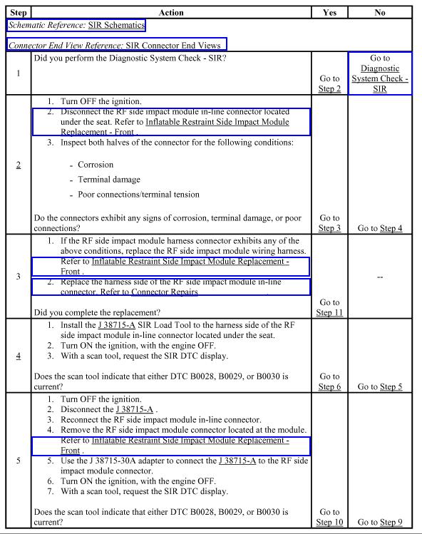
5 DIAGNOSTIC AIDS The following can cause an intermittent condition: A short between the RF side impact module high and RF side impact module low control circuits. An open or high resistance in the RF side impact module high or RF side impact module low control circuits. A malfunctioning shorting bar on the RF side impact module connector. Refer to Testing for Intermittent Conditions and Poor Connections. TEST DESCRIPTION The numbers below refer to the step numbers on the diagnostic table. 2. Inspects the RF side impact module inline connector. 4. Tests for a malfunctioning RF side impact module. 7. If DTC B0028 is present, test for a short between the RF side impact module high and RF side impact low control circuits. If DTC B0029 is present, test for an open or high resistance in the RF side impact module high and RF side impact module low control circuits. If DTC B0030 is present, test for a short to ground or voltage in the RF side impact module high and RF side impact module low control circuits.
P2122. P Accelerator Pedal Position Sensor 1 Circuit Low
 Page 1 of 10 Home Account Contact ALLDATA Log Out Help DAN GRIMWOOD DAN GRIMWOOD00002 Select Vehicle New TSBs Technician's Reference Component Search: OK 2006 Dodge Truck RAM 1500 Truck 2WD V8-5.7L VIN
P2121-ACCELERATOR PEDAL POSITION SENSOR 1 PERFORMANCE
 8 - D - RAM 5 PICKUP -.7L CUMMINS TURBO DIESEL P- SENSOR PERFORMANCE CONTROL 5 VOLT SUPPLY APPS NO. SIGNAL APPS NO. RETURN APPS NO. RETURN APPS NO. SIGNAL 5 VOLT SUPPLY C 4 C C 8 C 5 C 7 C K854 8 VT/BR
B1C27-13-LEFT SIDE THORAX SQUIB 1 CIRCUIT OPEN SEAT/CURTAIN SQUIBS. Theory of Operation. Diagnostic Test
 1 of 6 9/21/2014 10:03 AM B1C27-13-LEFT SIDE THORAX SQU... What's this THORAX SQUIB 1 CIRCUIT OPEN B1C27-13-LEFT SIDE For a complete wiring diagram, refer to the Wiring Information. SEAT/CURTAIN SQUIBS
P0137-O2 SENSOR 1/2 CIRCUIT LOW
 6 - DR - RAM 5 PICKUP - 5.7L HEMI V8 - MDS P7-O SENSOR / CIRCUIT LOW O / HEATER O RETURN (DOWNSTREAM) 9 C C K99 8 BR/WT K9 8 7 C S87 S68 K99 K9 K9 8 8 8 BR/WT TO OTHER MODULES Z 8 BK/LB K 8 DB/YL G7 C
The methods these electronic controllers use to communicate among themselves (and the way we diagnose them) have also evolved.
 have also evolved.") To keep pace with increasingly sophisticated safety, fuel economy, emissions, vehicle handling, comfort and convenience, and driver information systems, the number of electronically controlled circuits
To keep pace with increasingly sophisticated safety, fuel economy, emissions, vehicle handling, comfort and convenience, and driver information systems, the number of electronically controlled circuits
 Page 1 of 6 Possible Sources Obstructions in the GPS antenna's line of sight GPS coaxial cable between the APIM and satellite radio/gps splitter Satellite radio/gps splitter Rear satellite radio/gps coaxial
SCI ISO-K CCD PCI CAN
 DCX Networks SCI (Serial Communication Interface): The system uses two wires; one to transmit and one to receive. ISO-K is the adaptation of the 9141 standards allowing two-way communication on a single
2007 Hummer H ACCESSORIES AND EQUIPMENT Cellular, Entertainment and Navigation - H3
 SPECIFICATIONS FASTENER TIGHTENING SPECIFICATIONS 2007 ACCESSORIES AND EQUIPMENT Cellular, Entertainment and Navigation H3 Fastener Tightening Specifications Specification Application Metric English Antenna
LAN SYSTEM SECTION LAN CONTENTS K ELECTRICAL LAN-1 CAN CAN FUNDAMENTAL
 K ELECTRICAL SECTION LAN A LAN SYSTEM B C D CONTENTS E CAN FUNDAMENTAL PRECAUTIONS... 3 Precautions When Using CONSULT-II... 3 Precautions for Trouble Diagnosis... 3 Precautions for Harness Repair... 3
# : Servicing Vehicles Upgraded to OnStar Generation 6 Digital-Capable System - Follow Information Below - (Apr 9, 2009)
") #09-08-46-001: Servicing Vehicles Upgraded to OnStar Generation 6 Digital-Capable System - Follow Information Below - (Apr 9, 2009) Subject: Servicing Vehicles Upgraded to OnStar Generation 6 Digital-Capable
#09-08-46-001: Servicing Vehicles Upgraded to OnStar Generation 6 Digital-Capable System - Follow Information Below - (Apr 9, 2009) Subject: Servicing Vehicles Upgraded to OnStar Generation 6 Digital-Capable
LAN SYSTEM SECTION LAN CONTENTS ELECTRICAL LAN-1 CAN FUNDAMENTAL SERVICE INFORMATION... 2
 ELECTRICAL SECTION LAN A LAN SYSTEM B C D CONTENTS E CAN FUNDAMENTAL SERVICE INFORMATION... 2 PRECAUTIONS... 2 Precaution for Trouble Diagnosis...2 Precaution for Harness Repair...2 SYSTEM DESCRIPTION...
Mirage B-34 FEATURES SPECIFICATIONS
 Mirage B-34 Mirage B-34 Instruction Manual The Mirage B-34 is a linear power amplifier designed for the 144-148 MHz band. It is the most useful and versatile amplifier available for handheld transceiver.
USER MANUAL D-CLASS AMPLIFIER CA-DA12250 CA-DA41400 CA-DA Specifications and design are subject to change without notice
 USER MANUAL D-CLASS AMPLIFIER CA-DA12250 CA-DA41400 CA-DA51600 Specifications and design are subject to change without notice AMPLIFIER SPECIFICATIONS CA-DA12250 CA-DA41400 CA-DA51600 Peak Power (Watts)
COMPONENT LOCATION INDEX
 COMPONENT LOCATION INDEX 2004 ACCESSORIES & EQUIPMENT Audio System - TSX Fig. 1: Locating Audio System Components (1 Of 2) Tuesday, March 11, 2008 3:35:47 3:35:51 PM Page 1 Fig. 2: Locating Audio System
Q: What does it mean if the RF generator will not put out full power and the reflected power is nearly equal to forward power?
 Q: What does it mean if the RF generator will not put out full power and the reflected power is nearly equal to forward power? A: This generally means that the generator is in "reflected foldback." The
LFA4-840 / LFA / LFA LFA1-2000D / LFA1-4000D / LFA1-5500D LFA2-420 / LFA2-600 / LFA2-800 LFA / LFA / LFA / LFA2-2600
 OWNERS MANUAL LFA4840 / LFA41200 / LFA41600 LFA12000D / LFA14000D / LFA15500D LFA2420 / LFA2600 / LFA2800 LFA21250 / LFA21800 / LFA22200 / LFA22600 INTRODUCTION Power Acoustik amplifiers provide highperformance
 Page 1 of 6 Pinpoint Test K: The Satellite Radio Is Inoperative/Does t Operate Correctly Vehicles Without Navigation rmal Operation Vehicles Without Navigation Reception can be affected by obstructions
Diagnosing a no-start issue on a Chrysler Town and Country By: Brandon Steckler
 Diagnosing a no-start issue on a Chrysler Town and Country By: Brandon Steckler Recently I was asked to meet a kind, older gentleman in our parking lot at the shop. This patient, old man wanted to speak
Wave and Antenna Training System [WATS-2002]
![Wave and Antenna Training System [WATS-2002]](/thumbs/75/71704193.jpg "Wave and Antenna Training System [WATS-2002]") Wave and Antenna Training System [WATS-2002] 1. System configuration 2. Characteristics The majority of existing antenna practice devices identified only radiation pattern of antenna based on fixed radio
Wave and Antenna Training System [WATS-2002] 1. System configuration 2. Characteristics The majority of existing antenna practice devices identified only radiation pattern of antenna based on fixed radio
2004 ACCESSORIES & EQUIPMENT. Entertainment - Corvette. Fastener Tightening Specifications Specification Application
 2004 ACCESSORIES & EQUIPMENT Entertainment - Corvette SPECIFICATIONS FASTENER TIGHTENING SPECIFICATIONS Fastener Tightening Specifications Specification Application Metric English Antenna Buffer Retaining
PACSystems* RX3i and Series 90-30
 May 2012 PACSystems* RX3i and Series 90-30 Series 90*-30 Analog Output Module, Current/Voltage, 8 Channel, IC693ALG392 RX3i Analog Output Module, Current/Voltage, 8 Channel, IC694ALG392 The PACSystems
CAN BUS TROUBLESHOOTING
 2003 BMW X5 4.4i (E53) V8-4398cc 4.4L DOHC (M62 TU) Vehicle > Powertrain Management > Computers and Control Systems > Information Bus > Testing and Inspection > Initial Inspection and Diagnostic Overview
SURFACE VEHICLE RECOMMENDED PRACTICE
 SURFACE VEHICLE RECOMMENDED PRACTICE J1939-05 Issued 2008-02 ISSUED FEB2008 Marine Stern Drive and Inboard Spark-Ignition Engine On-Board Diagnostics Implementation Guide RATIONALE This recommended practice
Servo Amplifier - Troubleshooting Guide
 Haas Technical Documentation Servo Amplifier - Troubleshooting Guide Scan code to get the latest version of this document Translation Available There are four versions of Haas amplifiers. 30A [1], 45A
PLANNING YOUR SYSTEM
 INTRODUCTION HERTIAGE amplifiers provide high-performance sound reinforcement for your mobile audio equipment. Its versatility enables compatibility with optional Equalizers, Frequency Dividing Crossover
WARNING: DO NOT PROCEED WITHOUT READING THIS PAGE.
 WARNING: DO NOT PROCEED WITHOUT READING THIS PAGE. The B-1030-G produces at least 300 watts of VHF R.F. power and is not to be taken lightly. Severe R.W. burns can be sustained at this power level! Power
WARNING: DO NOT PROCEED WITHOUT READING THIS PAGE.
 WARNING: DO NOT PROCEED WITHOUT READING THIS PAGE. The B-2530-G produces at least 300 watts of VHF R.F. power and is not to be taken lightly. Severe R.W. burns can be sustained at this power level! Power
IOCs with Redundancy Support
 IOCs with Redundancy Support EPICS Collaboration Meeting, Spring 2012 Jörg Penning (DESY / MKS-2) 1 Overview Goals Principle of operation Design of the redundant IOC Experiences from operation Conclusion
Information and Entertainment System
 SECTION 415-00: Information and Entertainment Systems 2009 Mustang Workshop Manual DIAGNOSIS AND TESTING Procedure revision date: 09/23/2008 Information and Entertainment System Special Tool(s) 73III Automotive
ANTENNAFIER TM 915LTX BLOCK DIAGRAM LNA
 Digitally Tunable 0.5 to 10 Watts This 915 LTX is a Outdoor High Power Digitally Tunable Bi-Directional Amplifier for 802.11b/g WLAN. It s tuned and powered over a 50 Ohm coax. Now you can fine tune your
Coil On Plug Ignition: The Wired Differences
 Southern Illinois University Carbondale OpenSIUC Presentations Department of Automotive Technology 10-5-2011 Coil On Plug Ignition: The Wired Differences Matt Dixon Southern Illinois University Carbondale,
GUIDE FOR WIRING HARNESS AND CONNECTOR REPAIR. This bulletin supersedes TSB 15-BE-004 to update the wiring connector ordering information.
 Technical Service Bulletin GROUP BODY ELECTRICAL DATE JUNE, 2017 NUMBER MODEL(S) 17-BE-006 ALL This bulletin supersedes TSB 15-BE-004 to update the wiring connector ordering information. Description: This
Product overview. Features. Product specifications. Order codes. 1kΩ Resistance Output Module
 Product overview The AX-ROM135 and the AX-ROM1000 Modules enable an Analogue, Pulse or Floating point signal and convert to either a 0-135Ω or a 1KΩ Proportional Resistive output signal. The output resistance
OPERATING AND MAINTENANCE MANUAL
 5Hz to 1MHz WIDE RANGE FULLY AUTOMATIC DISTORTION ANALYZER MODEL 6900B SERIAL NO. OPERATING AND MAINTENANCE MANUAL Unit 4, 15 Jonathan Drive, Brockton, MA 02301-5566 Tel: (508) 580-1660; Fax: (508) 583-8989
Technical Service Bulletin
 Page 1 of 44 Technical Service Bulletin SUBJECT: DIAGNOSTIC TROUBLE CODES FOR CENTER DISPLAY ADDED - SERVICE MANUAL REVISION No: DATE: February, 2009 MODEL: 2004-08 Endeavor CIRCULATE TO: [ ] GENERAL MANAGER
MIRAGE BD-35 DUAL BAND POWER AMPLIFIER
 MIRAGE BD-35 DUAL BAND POWER AMPLIFIER INTRODUCTION: The Mirage BD-35 is a 45/35 watt dual band power amplifier for use with today's dual band handie talkies operating in the 144/440MHz bands. We have
Ortel (Lucent) Fiber Optic Interface
 Fiber Optic Interface") Ortel (Lucent) Fiber Optic Interface 144-701-1 Serial Number January 31, 2013 Part number 098-00120-000 Revision C ORTEL (LUCENT) FIBER OPTIC INTERFACE 1. GENERAL INFORMATION...1 1.1. SCOPE OF OPTION...1
Ortel (Lucent) Fiber Optic Interface 144-701-1 Serial Number January 31, 2013 Part number 098-00120-000 Revision C ORTEL (LUCENT) FIBER OPTIC INTERFACE 1. GENERAL INFORMATION...1 1.1. SCOPE OF OPTION...1
Additions, Revisions, or Updates
 1 10 10-14 SUBJECT DATE SPN 2623 (CPC) (GHG14) October 2014 Additions, Revisions, or Updates Publication Number / Title Platform Section Title Change SPN 2623/FMI 2 - DDC-SVC-MAN-0084 GHG14 DD Platform
INDEX PREFACE... 1 CAUTIONS... 2 OPERATION ON SITE(9) STANDARD INSTRUMENT... 3 OPTIONAL ACCESSORIES... 4 OPERATION OF TRANSMITTER(3)...
 STANDARD INSTRUMENT... 3 OPTIONAL ACCESSORIES... 4 OPERATION OF TRANSMITTER(3)...") INDEX PREFACE... 1 CAUTIONS... 2 STANDARD INSTRUMENT... 3 OPTIONAL ACCESSORIES... 4 OPERATION OF TRANSMITTER(1)... 5 (Transmitter Unit.) OPERATION OF TRANSMITTER(2)... 6 (Operation Panel, LCD Display of
INDEX PREFACE... 1 CAUTIONS... 2 STANDARD INSTRUMENT... 3 OPTIONAL ACCESSORIES... 4 OPERATION OF TRANSMITTER(1)... 5 (Transmitter Unit.) OPERATION OF TRANSMITTER(2)... 6 (Operation Panel, LCD Display of
Mirage B-310-G FEATURES
 Mirage B-310-G Mirage B-310-G Instruction Manual The Mirage B-310-G is a VHF power amplifier designed for the 144-148 MHz band. New features make it the most useful and versatile amplifier available for
HAU Series Controllers
 Instruction, Installation and Operation Guide for: HAU Series Controllers Document Number: 021-00140 Document Revision: B.2 Document Issue Date: Document Creator: G.Gotting Document Creation Date: 4/21/2011
************* OWNER'S MANUAL STAX1250/2 STAX1800/2 STAX2200/2 STAX1200/4 STAX1600/4 STAX2300/4 STAX2000/1D STAX4000/1D STAX5500/1D
 ************* OWNER'S MANUAL STAX1250/2 STAX1800/2 STAX2200/2 STAX1200/4 STAX1600/4 STAX2300/4 STAX2000/1D STAX4000/1D STAX5500/1D INTRODUCTION Power Acoustik amplifiers provide high-performance sound
Contents. Warranty and Disclaimer 2 Introduction 3
 Contents Warranty and Disclaimer 2 Introduction 3 Physical Dimensions Board Layout 4 Servo connections 5 Using the Serv8 Usage 6 Setting the start address 7 Setting the pulse width 8 Using the configuration
FTPM01 MEMS. Specifications Tire Pressure Monitoring System FTPM01 Rev 2.0, 5/2011
 Tire Pressure Monitoring System Rev 2.0, 5/2011 Key Features Description The is tire pressure monitoring system which is designed for auto manufacturer. It is compatible with American final rule released
Radio Control Installation and Operating Instructions System 4
 Radio Control Installation and Operating Instructions System 4 P.O. Box 403, One Cedar Parkway, Jackson, WI 53037 Phone: 800-628-1909 Fax: 262-677-2058 Revision: April 19, 2012 Contents Introduction 3
Technical Information
 Product Group: LIGHTING Model: LT-12D This bulletin is provided for technical reference and service related updates. If you have any questions, comments or do not wish to receive these e-mails, please
Ortel (Lucent) Fiber Optic Interface
 Fiber Optic Interface") Ortel (Lucent) Fiber Optic Interface 144-701-1 Serial Number May 5, 2009 Revision B ORTEL (LUCENT) FIBER OPTIC INTERFACE 1. GENERAL INFORMATION... 1 1.1. SCOPE OF OPTION... 1 1.2. PURPOSE OF EQUIPMENT...
Ortel (Lucent) Fiber Optic Interface 144-701-1 Serial Number May 5, 2009 Revision B ORTEL (LUCENT) FIBER OPTIC INTERFACE 1. GENERAL INFORMATION... 1 1.1. SCOPE OF OPTION... 1 1.2. PURPOSE OF EQUIPMENT...
Eight channel remote relay card. Total solder points: 277 Difficulty level: beginner advanced K8056 ILLUSTRATED ASSEMBLY MANUAL
 Eight channel remote relay card This relay card can be used in several ways : stand alone card, addressed by switches or open collector outputs or remote controlled through RS232. Total solder points:
Vibrating Wire Instrumentation
 Vibrating Wire Instrumentation Design, Operations & Lines Test Results System Diagram - Fig 1 Sensor Excitation Circuit Differential Amplifier + + Sensor Coil - - High Pass 100 Hz Digital Filter Low Pass
T25-35SA Subaudible Tone Decoder
 T25-35SA Subaudible Tone Decoder The Mueller Broadcast Design T25-35SA subaudible tone decoder provides a simple and reliable way to detect the 25 and 35 Hz control tones sent by many satellite-delivered
INTRODUCTION. Please read this manual carefully for a through explanation of the THETA Pre-Amplifier and its functions.
 INTRODUCTION Congratulations on your purchase of the Theta stand alone pre-amplifier. You are now the owner of the most innovative guitar amplifier ever produced. The same innovation and killer sound that
Antenna Creation and Installation Instructions
 Antenna Creation and Installation Instructions Antenna Creation and Installation Introduction There are two methods for setting up the antenna for the RMS. We have the single loop and two loop methods.
AVL & Data Logging System
 AVL & Data Logging System System overview & Installation Guide WM1002 B Issue 1 page 1 of 13 Contents 1. Operation Page System Configuration....3 System Overview...3 System Operation...4 Component Layout...
APSM-1300/APSM
 APSM-1300/APSM-1500 1 2 3 4 15 14 6 7 9 8 5 10 11 13 12 APSM-2000 1 2 3 4 15 14 6 7 9 8 5 10 11 13 12 1 Speaker connection Never connect the speaker cables with the chassis ground. This may destroy your
Teaching Computer Control using Cause and Effect Relationships Hands-On
 4210 rue Jean-Marchand, Quebec, QC G2C 1Y6, Canada Phone: 418 688 9067 / 800 567 0791 / 810 222 4525 (USA) Fax: 418 843 3444 / Email: info@ A ConsuLab Presentation Teaching Computer Control using Cause
Reception Diagnosis Using Antenna Test Kit
 L-SB-0008-15 March 31, 2015 Service Category Audio/Visual/Telematics Section Audio/Video Market USA Applicability YEAR(S) MODEL(S) ADDITIONAL INFORMATION 1990 2015 CT200H, ES250, ES300, ES300H, ES330,
Operating Instructions
 UltraDTEK Vehicle Loop Detector Operating Instructions PRODUCT OVERVIEW The UltraDTEK vehicle loop detector is plug-in compatible with Elite OmniControl TM board operators and other Elite A ELD enabled
Arduino and Servo Motor
 Arduino and Servo Motor 1. Basics of the Arduino Board and Arduino a. Arduino is a mini computer that can input and output data using the digital and analog pins b. Arduino Shield: mounts on top of Arduino
Technical Service Information Bulletin
 Technical Service Information Bulletin April 6, 2006 Title: Models: 01 07 All Lexus AU001-06 AUDIO Introduction Lexus has developed a quick reference guide to be used by technicians when troubleshooting
Testing for EMC Compliance: Approaches and Techniques October 12, 2006
 : Approaches and Techniques October 12, 2006 Ed Nakauchi EMI/EMC/ESD/EMP Consultant Emulex Corporation 1 Outline Discuss EMC Basics & Physics Fault Isolation Techniques Tools & Techniques Correlation Analyzer
AMU-214 Auxiliary Monitor Unit Operations Manual
 AMU-214 Auxiliary Monitor Unit THIS MANUAL CONTAINS TECHNICAL INFORMATION FOR THE AMU-214 SERIES ITS CABINET AUXILIARY MONITOR UNIT. REVISION: SEPTEMBER 2008 pn 888-0214-001 THE AMU-214 SERIES AUXILIARY
This section lists the specications for the Agilent 8360 B-Series. generators, Agilent Technologies has made changes to this product
 2c Specifications This section lists the specications for the Agilent 8360 B-Series swept signal generator. In a eort to improve these swept signal generators, Agilent Technologies has made changes to
Service Information System
 Quick Notes Page 1 Service Information System Thursday, September 01, 2016 7:22 AM Troubleshooting C32 Marine Auxiliary Engines Media Number -KENR6846-04 Publication Date -01/07/2011 Date Updated -15/07/2011
BETWEEN SCAN TOOL & SUCCESSFUL DIAGNOSIS FILLING IN THE GAPS
 ETWEEN SCAN TOOL & SUCCESSFUL DIAGNOSIS FILLING IN THE GAPS 38 April 0 Y ERNIE THOMPSON A scan tool is an invaluable aid to vehicle diagnostics, but you may need to rely on other methods as well when vital
INSTRUCTION MANUAL DAAB LOOP DETECTOR DB402
 INSTRUCTION MANUAL DAAB LOOP DETECTOR DB402 1st Edition Revision: 3 FAAC Nordic AB BOX 125, SE-284 22 PERSTORP SWEDEN TEL. +46 435 77 95 00 FAX +46 435 77 95 29 www.faac.se Contents Technical data...2
Voltage Probe Manual and Data North Star High Voltage, Inc. Rev January 2016
 561 Rose Loop NE Bainbridge Island, WA, USA 9811 (52)78-93; (26)219-425 FAX http://www.highvoltageprobes.com probes@highvoltageprobes.com Voltage Probe Manual and Data North Star High Voltage, Inc. Rev
Four Channel Inductive Loop Detector
 Naztec Operations Manual For Four Channel Inductive Loop Detector Model 724/224 April 2003 Published by: Naztec, Inc. 820 Park Two Drive Sugar Land, Texas 77478 Phone: (281) 240-7233 Fax: (281) 240-7238
M170 Belt Pack Transmitter OPERATING INSTRUCTIONS and trouble-shooting guide LECTROSONICS, INC. Rio Rancho, NM
 M170 Belt Pack Transmitter OPERATING INSTRUCTIONS and trouble-shooting guide LECTROSONICS, INC. Rio Rancho, NM INTRODUCTION Thank you for selecting the M170 Series transmitter. The M170 Series transmitters
IMPORTANT! Please take the time to read through the manual before you start to install/program your equipment.
 PRODUCT DESCRIPTION IMPORTANT! Please take the time to read through the manual before you start to install/program your equipment. The systems KRC11, 12, 13 and 14 consists of two parts: the transmitter
Quest Self Check 3 Front Panel FET & ZIF Connector Checker
 Quest Self Check 3 Front Panel FET & ZIF Connector Checker for Megatest Q2/62 System Manual P/N: 101234 Ver. 3.0 Load Bd P/N: 101431 Ver. 1 REFERENCE MANUAL Quest Self Check 3 Front Panel FET & ZIF Connector
Diversity Antenna Distribution Module DADM226. Instruction manual
 Diversity Antenna Distribution Module DADM226 Instruction manual Contents Contents... 2 Diversity Antenna Distribution Module (DADM 226)... 3 Operating Elements... 4 Setting up Procedure... 5 Setting up
Antenna Creation and Installation Instructions
 Antenna Creation and Installation Instructions Introduction The detection loop antenna picks up signals from the transponders and passes them through to the decoder. There are two methods for setting up
AM/FM 10 METER MOBILE AMATEUR TRANSCEIVER OPERATING MANUAL
 AM/FM 10 METER MOBILE AMATEUR TRANSCEIVER OPERATING MANUAL INTRODUCTION Congratulations on your purchase of a Magnum S-6 AM/FM 10 meter transceiver. Your Magnum S-6 is designed to provide years of enjoyment
Keysight Technologies Essential Capabilities of EMI Receivers. Application Note
 Keysight Technologies Essential Capabilities of EMI Receivers Application Note Contents Introduction... 3 CISPR 16-1-1 Compliance... 3 MIL-STD-461 Compliance... 4 Important features not required by CISPR
B & D Enterprises 1P repeater controller pg 1 INTRODUCTION:
 B & D Enterprises 1P repeater controller pg 1 INTRODUCTION: The 1P is a basic repeater controller. The controller uses low power devices and stores all commands and system status in non-volatile EE prom.
Essential Capabilities of EMI Receivers. Application Note
 Essential Capabilities of EMI Receivers Application Note Contents Introduction... 3 CISPR 16-1-1 Compliance... 3 MIL-STD-461 Compliance... 4 Important features not required by CISPR 16-1-1 or MIL-STD-461...
Electronically Commutated (EC) Motor Control with Solo, Select and Sync PWM Boards
 Motor Control with Solo, Select and Sync PWM Boards") Electronically Commutated (EC) Motor Control with Solo, Select and Sync PWM Boards The Solo, Select and Sync PWM boards provide a pulse-width modulated (PWM) signal to the EC motor to control fan speed.
Electronically Commutated (EC) Motor Control with Solo, Select and Sync PWM Boards The Solo, Select and Sync PWM boards provide a pulse-width modulated (PWM) signal to the EC motor to control fan speed.
TLS-3A. Telephone Line Simulator. User Manual , Rev. B Covers Model TLS-3A-01
 User Manual TLS-3A Telephone Line Simulator 40-400-00010, Rev. B Covers Model TLS-3A-01 Teltone Corporation 22121-20th Avenue SE Bothell, Washington 98021-4408 USA Phone: 1-800-426-3926 or 425-487-1515
5 Mbit/s Repeater Carrierband to Single-mode Fiber Optic
 Installation and Testing 5 Mbit/s Repeater Carrierband to Single-mode Fiber Optic Models CBR-7AC CBR-7DC This manual describes the procedures for installing and testing the CBR-7 Fiber-Optic Repeaters.
MS2000 performs calibration on ADEPT card on startup, so the system maintains calibration.
 ASIs Drive Electronics for Piezo Top-Plate ADEPT s Features: Closed loop operation with strain gauge feedback. Auto strain gauge calibration on startup. Accepts inputs from MS2000 (digital) or external
COM-POWER OPERATION MANUAL ACS W
 COM-POWER OPERATION MANUAL For the ACS-250-100W 150 khz to 250 MHz 100W Power Amplifier Page 1 of 15 MANUAL_ACS-250-100W Rev. M02.15 Table of Contents Important Safety Precautions.....3 Introduction..5
CL-SSI. CleanSweep OWNER S MANUAL. signal-summing interface
 CleanSweep signal-summing interface OWNER S MANUAL Thank you for purchasing a JL Audio CleanSweep Signal-Summing Interface for your automotive sound system. This product has been designed and manufactured
INSPECTION 1. Take the cover off the relay, taking care to not shake or jar the relay or other relays around it.
 CEH51A SCOPE This test procedure covers the testing and maintenance of the GE CEH51A loss of excitation relay. Refer to IL GEK-27887 for testing support information and component level identification.
Grounding and Bonding
 Grounding and Bonding 2017 Communications Academy Joe Blaschka Jr., PE Grounding/Bonding What is it? Why do we do it? What does the National Electrical Code say? What about fixed locations? What about
This Datasheet is for the IC693ALG391. Analog Current Output - 2 Channel.
 This Datasheet is for the Analog Current Output - 2 Channel http://www.cimtecautomation.com/parts/p-14575-ic693alg391.aspx Provides the wiring diagrams and installation guidelines for this GE Series 9-3
APPLICATION NOTE 735 Layout Considerations for Non-Isolated DC-DC Converters
 Maxim > App Notes > AUTOMOTIVE GENERAL ENGINEERING TOPICS POWER-SUPPLY CIRCUITS PROTOTYPING AND PC BOARD LAYOUT Keywords: printed circuit board, PCB layout, parasitic inductance, parasitic capacitance,
Series and Parallel DC Circuits
 Series and Parallel DC Circuits asic Circuits n electric circuit is closed loop of conductive material (metal wire) that connects several circuit elements together (batteries, resistors, capacitors, etc.)
Keychain Radio Remote Control System
 Innovation in Mobility Keychain Radio Remote Control System Operator Manual 04/23/02 95-2002 RICON CORPORATION All Rights Reserved U.S. and foreign patents pending Printed in the United States of America
Coax ClarifierTM. User Manual. Test. Identify. Qualify. See video demonstrations at:
 Coax ClarifierTM Test. Identify. Qualify. User Manual Coax Run Mapping Maps runs through splitters to show an accurate picture of the coax system layout using up to 4 Coax RF Remotes. Up to 12 ID Only
Operator Manual 1.4 FRACSIM MINI
 FracSim Meters FracSim Meters was founded with the intention of providing specifically designed tools for the well service industry. Our goal is to provide quality tools with a robust design to meet the
INTRODUCTION. Please read this manual carefully for a through explanation of the THETA Head and its functions. PRECAUTIONS
 INTRODUCTION Congratulations on your purchase of the THETA Head. You are now the owner of the most innovative guitar amplifier ever produced. The THETA Head was designed to provide the maximum possible
INSTRUCTIONS: LUBELL LABS VC2C UNDERWATER SPEAKER
 INSTRUCTIONS: LUBELL LABS VC2C UNDERWATER SPEAKER WARNING: FOR USE AND SUPERVISION BY OCEAN ENGINEER ONLY! The Lubell Labs VC2C is an underwater acoustic transducer covering the frequency range of 50 Hz
Ortel (Lucent) Fiber Optic Interface AC
 Fiber Optic Interface AC") Ortel (Lucent) Fiber Optic Interface 144-701-1AC Serial Number March 11, 2010 CD P/N 098-00126-000 Revision B ORTEL (LUCENT) FIBER OPTIC INTERFACE 1. GENERAL INFORMATION... 1 1.1. SCOPE OF OPTION... 1
Ortel (Lucent) Fiber Optic Interface 144-701-1AC Serial Number March 11, 2010 CD P/N 098-00126-000 Revision B ORTEL (LUCENT) FIBER OPTIC INTERFACE 1. GENERAL INFORMATION... 1 1.1. SCOPE OF OPTION... 1
Installation Instructions
 Installation Instructions Garage Door Opener Radio Controls Model 5010 (300 mhz) \ 5012 (310 mhz) Single Button Transmitters Model 5100-01 (300 mhz) \ 5102-01 (310 mhz) Receivers WARNING: Disconnect operator
Inductive Loop Detector
 Naztec Operations Manual For Inductive Loop Detector Model 722TXC TS1/TS2 April 2003 Published by: Naztec, Inc. 820 Park Two Drive Sugar Land, Texas 77478 Phone: (281) 240-7233 Fax: (281) 240-7238 Copyright
MW3105 DIGITAL CLAMP MULTIMETER
 MW3105 DIGITAL CLAMP MULTIMETER 2 M MW3105 A 01 INTRODUCTION 1.1 - Unpacking and inspection Upon removing your new Digital Clamp Meter from its packing, you should have the following items: 1. Digital
RC2 REMOTE LEVEL CONTROL MODULE OPERATING INSTRUCTIONS
 RC REMOTE LEVEL CONTROL MODULE OPERATING INSTRUCTIONS and trouble-shooting guide LECTROSONICS, INC. Rio Rancho, NM INTRODUCTION The RC Remote Level Control Module provides channels of DC remote control
INSTALLATION AND OPERATION MANUAL
 RADIO/CAN REMOTE CONTROL SYSTEM -PRELIMINARY- INSTALLATION AND OPERATION MANUAL SDP GREEN 3B1151AJ.doc September 3, 2009 AP INDEX DESCRIPTION... 2 TRANSMITTER AND RECEIVER SYNCHRONIZATION... 3 INDICATOR
Installation & Operation Manual SAGA1-K Series Industrial Radio Remote Control
 Installation & Operation Manual SAGA1-K Series Industrial Radio Remote Control Gain Electronic Co. Ltd. Table Of Contents Safety Considerations ------------------------------------------------------------2
CLASS D MONOBLOCK AMPLIFIER DM1500, DM2500 OWNER S MANUAL
 CLASS D MONOBLOCK AMPLIFIER DM1500, DM2500 OWNER S MANUAL INTRODUCTION Thank you for purchasing a DD Audio amplifier. DD Audio amplifiers are painstakingly designed to provide years of high-performance