INSTRUCTIONS: LUBELL LABS VC2C UNDERWATER SPEAKER
|
|
|
- Asher Hubbard
- 5 years ago
- Views:
Transcription

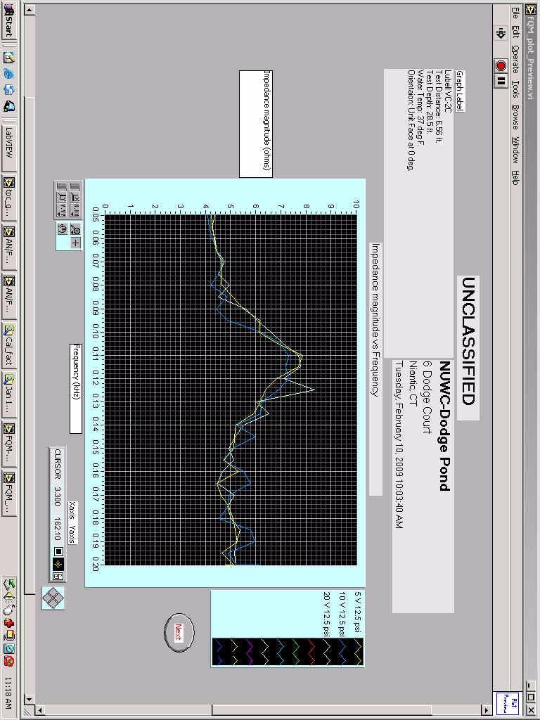
1 INSTRUCTIONS: LUBELL LABS VC2C UNDERWATER SPEAKER WARNING: FOR USE AND SUPERVISION BY OCEAN ENGINEER ONLY! The Lubell Labs VC2C is an underwater acoustic transducer covering the frequency range of 50 Hz to 1500 Hz at a maximum sound pressure level of 115 Hz. Sales of the VC2C are limited to marine scientists and laboratories, ocean engineers, and the military. Description: Axial symmetric dual-piston radiator with spring copper diaphragms and external stops Frequency Range: 50 Hz to 1.5 khz Resonant Frequency: 115 Hz +/- 5 Hz Impedance: Varies with frequency (4 ohms 50 Hz; Hz) Maximum Output Level: 174dB/uPa/m Maximum Voltage/Current: 20 Vrms/2.5A (100% duty cycle) Q Parameters: Qtco~2.5 Qmc~5 Directivity: Omnidirectional to 1.5 khz Cable: Teledyne Marine LPIL-3-FS on 50 feet 16/3 SO Minimum / Maximum Depth: 10 feet (3.05 meters) - 50 feet (15.24 meters) Maximum Air Pressure: 23 psi (WARNING: use provided hand air pump only!) Piston Stop Gap: inches (Schrader valve pin depressed to equalize internal/external pressure) Dimensions: 8"D x 9.75"L Weight: 21 lbs Included: Lubell VC2C underwater speaker, Teledyne LPIL-3-FS on 50 of SO cable, Blackburn hand pump, Accutire MS-4021B digital pressure gauge, and a Cabbage Cases carry case.
2 CAUTION: The Lubell VC2C is for sale to marine scientists and laboratories, ocean engineers, and the military. Set-up and operation of the VC2C must be supervised by an engineer having a background in ocean engineering, due to special pressure compensation requirements and potentially harmful sound levels. WARNING: MUST BE GROUNDED VIA CABLE (GREEN CONDUCTOR) OR #8 COPPER WIRE 23 PSI MAXIMUM AIR PRESSURE INFLATE WITH HAND PUMP ONLY PER INFLATION SCHEDULE OPERATING DEPTH: 10 FEET - 50 FEET DO NOT DEPRESS THE SCHRADER VALVE CORE PIN IN THE WATER 1. Equipment operator should wear dry rubber-soled shoes while setting up and operating equipment. 2. Inspect all equipment and cordage before use. Do not use equipment if cords are damaged. 3. Set up a wood or plastic insulated equipment table in a dry sheltered area keeping a minimum distance of 10 from the water. Keep equipment securely fastened in place if using on a boat or ship. 4. Attach a sturdy 3/8 inch three-strand polypropylene rope of sufficient length to the attachment eyelet on the VC2C underwater acoustic transducer. Depth markers should be placed on the rope in 1 foot intervals to determine the operating depth of the VC2C when deployed from vessel. 5. After lightly lubricating the pins with silicone grease, attach the Teledyne LPIL-3-FS 50 SO cable to the mating Teledyne LBPH-3-MP bulkhead connector fitted on the VC2C underwater speaker. IMPORTANT: Strain relief a loop in the SO cable using HD nylon cable ties so as to prevent any strain on the bulkhead connector. Failure to follow this procedure will likely result in expensive damage to the bulkhead connector, which will require factory replacement. 6. GROUNDING: Either ground the VC2C to an approved ship ground or tank ground via the green conductor in the SO cable or attach a flexible green 8 AWG THHN/THWN stranded ground wire of sufficient length to the screw on the bottom of the VC2C for this purpose. 7. IMPORTANT: Before lowering the VC2C underwater speaker into the water (from dry deployment area), depress the Schrader valve core pin to equalize (zero out) the internal air pressure of the VC2C with that of the surrounding atmospheric pressure. 8. IMPORTANT: Verify that both of the VC2C s piston-stop gaps are precisely set to inches, and that the set-screw lock-nut is securely tightened. 9. Determine and record the proposed operating depth for the VC2C tests. 10. The VC2C must then be precisely inflated with the supplied hand pump to the correct pressure corresponding to the intended depth of operation per following schedule: Freshwater: psi x depth of operation in feet; Saltwater: psi x depth of operation in feet. When pressurized, the piston-stop gaps will close while on the platform, but will then return to the preset inch gap once the VC2C is deployed to the prescribed depth of operation. (Practice measuring the pressure with the included Accutire MS-4021B digital pressure gauge, as each time you check the pressure, you release a small amount of air...pressure must be accurate!) WARNING: Disconnect the VC2C from amplifier if diver is verifying the inch piston-stop gap at depth. 11. Tether the VC2C at the test depth determined in step 9, and compensated for in step Connect VC2C to amplifier rated up to ohms (20 Vrms). Coding: White=Hot, Black=Return, Green=Ground. WARNING: Connect AC powered amplifier to GFCI outlet only. 13. To help protect the VC2C against burnout, install a 2.5A fast-blow fuse in the white signal wire.
3 DEPLOYMENT DEPTH VS REQUIRED INFLATION PRESSURE VC2C FRESHWATER 10 FEET = PSI 11 FEET = PSI 12 FEET = PSI 13 FEET = PSI 14 FEET = PSI 15 FEET = PSI 16 FEET = PSI 17 FEET = PSI 18 FEET = PSI 19 FEET = PSI 20 FEET = PSI 21 FEET = PSI 22 FEET = PSI 23 FEET = PSI 24 FEET = PSI 25 FEET = PSI 26 FEET = PSI 27 FEET = PSI 28 FEET = PSI 29 FEET = PSI 30 FEET = PSI 31 FEET = PSI 32 FEET = PSI 33 FEET = PSI 34 FEET = PSI 35 FEET = PSI 36 FEET = PSI 37 FEET = PSI 38 FEET = PSI 39 FEET = PSI 40 FEET = PSI 41 FEET = PSI 42 FEET = PSI 43 FEET = PSI 44 FEET = PSI 45 FEET = PSI 46 FEET = PSI 47 FEET = PSI 48 FEET = PSI 49 FEET = PSI 50 FEET = PSI SALTWATER 10 FEET = PSI 11 FEET = PSI 12 FEET = PSI 13 FEET = PSI 14 FEET = PSI 15 FEET = PSI 16 FEET = PSI 17 FEET = PSI 18 FEET = PSI 19 FEET = PSI 20 FEET = PSI 21 FEET = PSI 22 FEET = PSI 23 FEET = PSI 24 FEET = PSI 25 FEET = PSI 26 FEET = PSI 27 FEET = PSI 28 FEET = PSI 29 FEET = PSI 30 FEET = PSI 31 FEET = PSI 32 FEET = PSI 33 FEET = PSI 34 FEET = PSI 35 FEET = PSI 36 FEET = PSI 37 FEET = PSI 38 FEET = PSI 39 FEET = PSI 40 FEET = PSI 41 FEET = PSI 42 FEET = PSI 43 FEET = PSI 44 FEET = PSI 45 FEET = PSI 46 FEET = PSI 47 FEET = PSI 48 FEET = PSI 49 FEET = PSI 50 FEET = PSI
4 CALIBRATION OF LUBELL VC2C AT NUWC DODGE POND TUESDAY FEBRUARY :03:40 AM Lubell VC2C Se 50 Hz to 2 khz 12_5 psi 28 ft depth 20 V drive Frequency Transmit Transmit Real Z Phase TVR TCR SPL khz Voltage Current Power Magnitude (Z) db// db// volts amps watts ohms deg upa/volt upa/amp db//upa
5 CALIBRATION OF LUBELL VC2C AT NUWC DODGE POND TUESDAY FEBRUARY :03:40 AM Lubell VC2C Se 50 Hz to 2 khz 12_5 psi 28 ft depth 20 V drive Frequency Transmit Transmit Real Z Phase TVR TCR SPL khz Voltage Current Power Magnitude (Z) db// db// volts amps watts ohms deg upa/volt upa/amp db//upa
6
7
8
A short, off-center fed dipole for 40 m and 20 m by Daniel Marks, KW4TI
 A short, off-center fed dipole for 40 m and 20 m by Daniel Marks, KW4TI Version 2017-Nov-7 Abstract: This antenna is a 20 to 25 foot long (6.0 m to 7.6 m) off-center fed dipole antenna for the 20 m and
INSTALLATION MANUAL MULTICAST SPEAKER/ EXTREMECAST SPEAKER
 INSTALLATION MANUAL MULTICAST SPEAKER/ EXTREMECAST SPEAKER 1.0 INTRODUCTION The Multicast and Extremecast product families consist of single-channel and multi-channel units. All versions are available
Load Cell Accessories and Services
 Load Cell Accessories and Services Highlights Strain gage signal conditioners Cable assemblies Mounting accessories Calibration services PCB Piezotronics, Inc. Toll-Free in USA 888-684-0004 716-684-0001
Ambient Level Controller
 Ambient Level Controller Installation and Use Manual Issue 1, October 1999 1999 Bogen Communications, Inc. All rights reserved. 54-2028-01 9910 Model: LUALC PEC Code: 5335-621 COM Code: 408184273 Select
Torque Sensor Accessories and Services
 ------------------- Torque Sensor Accessories and Services Highlights Strain gage signal conditioners Cable assemblies Speed sensors Shunt calibration modules and thermocouples Calibration services PCB
SAGA PRO SERIES STEREO POWER AMPLIFIER OPERATION MANUAL
 SAGA PRO SERIES STEREO POWER AMPLIFIER OPERATION MANUAL INSTALLATION Use care in unpacking the amplifier, and be sure to save the carton and packing materials so that you can use them for moving, storing,
EVID High Performance Ceiling Speakers
 EVID High Performance Ceiling Speakers EVID-PC6.2 and EVID-PC8.2 en Installation Note en 3 Table of contents 1 Safety 4 2 Welcome 5 2.1 Important features 5 3 System overview 6 3.1 Packing list 6 3.2
DCM20 Series. Three-Function DC Power Meters. DCM20 DISPLAY PRODUCT OVERVIEW FEATURES
 www.murata-ps.com DCM0 Series FEATURES Displays DC volts, amperes, watts and kilowatts. Two display modes: continuous auto cycling or fixed. 9-7 VDC voltage operation. 0.5-7 VDC voltage measurement range.
EVID Surface Mount S Series - X Models
 EVID Surface Mount S Series - X Models EVID-S5.2XB EVID-S5.2XW en Installation manual en 3 Table of contents 1 Safety 4 1.1 Suspension 4 1.2 Notices 4 2 Introduction 5 2.1 System features 5 2.2 Product
TOA PROFESSIONAL POWER AMP
 Operating Instruction Manual TOA PROFESSIONAL POWER AMP Model P-150M, P-300M TOA ELECTRIC CO, LTD. KOBE, JAPAN Contents Precautions... 2 General Description... 2 Features... 3 Specifications... 4~5 Performance
KING-GAGE KING. ES2 Liquid Level Transmitter. Installation and Operation Instructions ma Liquid Level Transmitter EX-1834
 Effective: April 2007 (Replaces January 2007) KING-GAGE 4-20 ma Liquid Level Transmitter ES2 Liquid Level Transmitter Installation and Operation Instructions Since 1937 KING E N G I N E E R I N G C O R
Conic Systems Inc. INSTRUCTION MANUAL FOR DATATRAN C2547 UNIVERSAL AMPLIFIER MODULE
 Conic Systems Inc. INSTRUCTION MANUAL FOR DATATRAN C2547 UNIVERSAL AMPLIFIER MODULE FOR TECHNICAL OR SALES ASSISTANCE CONTACT CONIC SYSTEMS INC. AT TEL: 845.856.4313 OR FAX: 845.858.2824 EMAIL: INFO@CONICSYSTEMS.COM
Array Solutions. Model AS-AYL-4 4-way K9AY Loop System
 Array Solutions Model AS-AYL-4 4-way K9AY Loop System This is the popular K9AY Loop receiving antenna, as described in the September 1997 issue of QST, The K9AY Terminated Loop-A Compact, Directional Receiving
English KS-DR3005D POWER AMPLIFIER: INSTRUCTION MANUAL
 KS-DR005D POWER AMPLIFIER: INSTRUCTION MANUAL B5E-009-00/00 [W] WARNING If the fuse blows, first make sure the wires aren t touching to cause a short circuit then replace the old fuse with one with the
A Channel Amplifier
 Installation Manual A2150 2 Channel Amplifier Table of Contents Installation Requirements and Recommendations 1 What s included 1 Speaker Wire Recommendations 1 Setup 2 Rack Mounting 2 Individually Protected
AELIUS YPSILON POWER AMPLIFIER. OWNERS MANUAL V1 01/01/20010 All rights reserved
 AELIUS YPSILON POWER AMPLIFIER OWNERS MANUAL V1 01/01/20010 All rights reserved INTRODUCTION Thank you for trusting YPSILON ELECTRONICS. We assure you that you have made an excellent purchase. Your amplifier
Model 1791 VHF Radio User's Manual
 Model 79 VHF Radio User's Manual ALL WEATHER INC 65 NATIONAL DRIVE SACRAMENTO, CA 95834 WWW.ALWEATHERINC.COM 79 VHF RADIO USER'S MANUAL CONTENTS INTRODUCTION... Description... Transmitter Module... Power
SFP-1 and MFP-1 PINGER
 SFP- and MFP- PINGER OPERATION MANUAL 40 JW FISHERS MFG INC 93 COUNTY ST. E. TAUNTON, MA 078 USA (08) 8-7330; (800) 8-4744; FAX (08) 880-8949 Email: info@jwfishers.com WEB: www.jwfishers.com SPECIFICATIONS
KING-GAGE ES2. Installation and Operation Instructions Manual. Electronic Liquid Level Transmitter. ESR Serial No. Versions and Slimline Versions
 Effective: November 2009 (replaces August 2009) KING-GAGE ES2 Electronic Liquid Level Transmitter Installation and Operation Instructions Manual ESR Serial No. Versions and Slimline Versions 2009 King
Model 4800 O P E R AT I O N M A N U A L L O A D C E L L S U M M I N G T R A N S M I T T E R
 O P E R AT I O N M A N U A L Model 4800 L O A D C E L L S U M M I N G T R A N S M I T T E R CALEX Manufacturing Company, Inc. Concord, California 94520 Ph: 925/687-4411 800/542-3355 Fax: 925/687-3333 http://www.calex.com
ENCOUNTER AMPLIFIER MANUAL EN-1502 EN-3001 EN-3004
 ENCOUNTER ENCOUNTER AMPLIFIER MANUAL EN-1502 EN-3001 EN-3004 ENGLISH AMPLIFIER SPECIFICATIONS EN-3004 (4 Channel) Class Class-AB Class-AB EN-1502 (2 Channel) Power 1800 Watts 1000 Watts Frequency Response
INSTALLATION AND MAINTENANCE MANUAL FOR GROUND MONITOR GM-250 COPYRIGHT 1983 AMERICAN MINE RESEARCH, INC.
 INSTALLATION AND MAINTENANCE MANUAL FOR GROUND MONITOR GM-250 COPYRIGHT 1983 AMERICAN MINE RESEARCH, INC. MANUAL PART NUMBER 180-0036 ORIGINAL: 1-17-83 REVISION: B (8-26-86) NOT TO BE CHANGED WITHOUT MSHA
CON NEX HP. OWNER'S MANUAL Full Channel AM/FM Amateur Mobile Transceiver TABLE OF CONTENTS TUNING THE ANTENNA FOR OPTIMUM S.W.R..
 TABLE OF CONTENTS PAGE SPECIFICATIONS... 2 INSTALLATION... 3 LOCATION... 3 CON NEX - 4300HP MOUNTING THE RADIO... 3 IGNITION NOISE INTERFERENCE... 4 ANTENNA... 4 TUNING THE ANTENNA FOR OPTIMUM S.W.R..
Model 526T Series II Super Punch Microphone User Guide
 TRANSISTORIZED BASE STATION MICROPHONE Model 526T Series II Super Punch Microphone User Guide Replaces either ceramic or dynamic original equipment microphones Excellent response for single-sideband transmission
PROFESSIONAL POWER AMP
 Operating Instruction Manual PROFESSIONAL POWER AMP Model P-75D, P-150D, P-300D P-75D P-150D P-300D TOA Corporation KOBE, JAPAN Contents Precautions... 1 General Description... 2 Features... 2~ 3 Specifications...
LC31L-BAT Link Coupler
 Instruction Manual For the LC31L-BAT Link Coupler 09 March 2018 2012-2018 by Ralph Hartwell Spectrotek Services All rights reserved 2 RADIO FREQUENCY WARNING NOTICE If the LC31L-BAT is installed incorrectly
Installation & User Guide. For Powering Distributed Audio Systems A45-X2 TWO CHANNEL AMPLIFIER
 Installation & User Guide For Powering Distributed Audio Systems TWO CHANNEL AMPLIFIER A45-X2 A45-X2 TWO CHANNEL AMPLIFIER TABLE OF CONTENTS Features...1 Product Overview...2 Package Contents...4 Preparing
TECHNICAL MANUAL. SERIES AP5202 DC Strain Gage In-Line Amplifier ISO 9001/AS9100
 TECHNICAL MANUAL SERIES AP5202 DC Strain Gage In-Line Amplifier ISO 9001/AS9100 Due to the nature of technology, changes are inevitable. For latest technical specifications, see our website. Copyright
Technical Specifications KF853
 Technical Specifications F853 APPLICATIONS The F853 Virtual Array System is a long-throw two way horn-loaded loudspeaker designed to cover the frequency range from 2Hz to 17kHz. The frequency response
USER MANUAL. MODEL 2017A RS-232 to 20ma Current Loop Converter. SALES OFFICE (301) TECHNICAL SUPPORT (301)
 TECHNICAL SUPPORT (301)") USER MANUAL MODEL 2017A RS-232 to 20ma Current Loop Converter Part# 07M2017A-A Doc# 073021UA Revised 10/15/93 SALES OFFICE (301) 975-1000 TECHNICAL SUPPORT (301) 975-1007 http://www.patton.com 1.0 WARRANTY
USER MANUAL MODEL 2017A RS-232 to 20ma Current Loop Converter Part# 07M2017A-A Doc# 073021UA Revised 10/15/93 SALES OFFICE (301) 975-1000 TECHNICAL SUPPORT (301) 975-1007 http://www.patton.com 1.0 WARRANTY
200 Watt Passive Shunt Module
 Installation Instructions 200 Watt Passive Shunt Module (Catalog Number 9101-1183) Drives can require external power dissipation when large inertial loads are present. To ensure that faults due to excessive
CVS 4. Product Description. Features. Applications
 Product Description The Tannoy CVS4 is a full bandwidth ceiling speaker system comprising a 1mm (4. ) mid bass driver with a coaxially mounted 19mm (.75 ) high frequency section mounted in a vented, injection
SECTION BUILDING WIRE AND CABLE
 SECTION 260519 PART 1 GENERAL 1.1 SUMMARY A. Section Includes: 1. Building wire and cable. 2. Wiring connectors and connections. B. RELATED SECTIONS 1. Section 26 05 53 Electrical Identification. 2. Section
NOV 16 Rev L
 Terminating Modules 856196-[ ] for Use with Modular Plug Dual Terminators 1320840-[ ] Instruction Sheet 408-9743 17 NOV 16 Rev L Modular Plug Dual Terminator Automatic Circuit Tester (Terminators 1320840-1
12 TON HYDRAULIC SHOP PRESS. Instruction Manual. Please read this instruction manual carefully before use.
 12 TON HYDRAULIC SHOP PRESS Instruction Manual Please read this instruction manual carefully before use. IMPORTANT PLEASE READ THESE INSTRUCTIONS CAREFULLY. NOTE THE SAFETY INSTRUCTIONS AND WARNINGS. USE
Disc Gap Control DGC-2. Technical Manual
 GB Disc Gap Control DGC-2 Technical Manual Contents Introduction Electronic unit... 1 Tracer valve... 1 Technical data... 2 Component layout... 4 Functions, electronic unit Stepper motor operation...
ARCS WIDE SYSTEM ARCS FOCUS SYSTEM
 ARCS WIDE SYSTEM ARCS FOCUS SYSTEM user manual VERSION 1.2 www.l-a coustics.com ARCS WIDE TypeProduit user manual VERSION 1.2 SAFETY INSTRUCTIONS 1. Read this manual 2. Follow all SAFETY INSTRUCTIONS as
Quick Start Guide. Table of Contents
 Quick Start Guide Table of Contents Pre-Installation... 2 Safety Conventions... 3 General Descriptions... 4 Specifications... 5 Front Panel Functions... 8 Back Panel Functions... 9 Details of Plug-In Mode...
The DeltaGrip System. Safety and Operating Instructions. Trigger. Air Supply Connection. Handle Assembly. Air Line Assembly.
 The DeltaGrip System Safety and Operating Instructions Trigger Air Supply Connection Handle Assembly Air Line Assembly Punch Die Pneumatic Diaphragm Assembly Shackle, Pin & Jam Nut Jaw Frame Shoulder Screw
PRA Series of Radio and TV Amplifier Power Supplies
 PRA Series of Radio and TV Amplifier Power Supplies The PRA 420 is an antenna power supply, low noise MMIC amplifier and splitter combination to supply up to 24 Shipboard Radios and /or TV Receivers. It
Model A-5. Mid Range Wet/Wet Differential Pressure Transducer. A-5, Datenblatt Seite 1 DESCRIPTION FEATURES
 A-5, Datenblatt Seite 1 Model A-5 Mid Range Wet/Wet Differential Pressure Transducer DESCRIPTION Model A-5 mid-range Wet/Wet Differential is a bonded foil strain gage transducers designed to accept fluid
DC200A Displacement Clipper User Manual
 Trig-Tek DC200A Displacement Clipper User Manual Publication No. 980981 A Inc. 4 Goodyear, Irvine, CA 92618 Tel: (800) 722-2528, (949) 859-8999; Fax: (949) 859-7139 atsinfo@astronics.com atssales@astronics.com
2-Way Proportional Logic Cartridge Valve Model FE.. (Series 1X and 2X) PSI (315 bar) F with electrical connection 12 X Y
 PSI (315 bar) F with electrical connection 12 X Y") RA 9 /6.98 -Way Proportional Logic Cartridge Valve Model FE.. (Series X and X) Size 6... 6... 6 PSI (5 bar)... 75 GPM (8 L/min) RA 9 /6.98 Replaces: 5.9 Characteristics: Single land throttle valve (main
RA 9 /6.98 -Way Proportional Logic Cartridge Valve Model FE.. (Series X and X) Size 6... 6... 6 PSI (5 bar)... 75 GPM (8 L/min) RA 9 /6.98 Replaces: 5.9 Characteristics: Single land throttle valve (main
SONARRAY SR1 SYSTEM INSTRUCTION MANUAL
 SONARRAY SR1 SYSTEM INSTRUCTION MANUAL SONARRAY SR1 SYSTEM INSTRUCTION MANUAL Introduction Thank you for purchasing the SONARRAY SR1 SYSTEM speakers. When properly installed, these speakers will provide
Electromagnetic shakers operating guide Models F3, F4, F5B, F10
 Electromagnetic shakers operating guide Models F3, F4, F5B, F10 Caution: This manual should be read carefully before installation WARNING: OPERATION OF THE ELECTROMAGNETIC SHAKER IS SAFE WHEN THE INSTRUCTIONS
PLANNING YOUR SYSTEM
 INTRODUCTION HERTIAGE amplifiers provide high-performance sound reinforcement for your mobile audio equipment. Its versatility enables compatibility with optional Equalizers, Frequency Dividing Crossover
Installation Instructions Road King Classic Saddlebag Bezels
 Installation Instructions Road King Classic Saddlebag Bezels Thank you for your purchase of Bagger Audio Road King Classic Saddlebag Bezels for your Harley-Davidson motorcycle. We have carefully engineered
On-Line Cardio Theater Wireless Digital Transmitter Installation and Instruction Manual
 On-Line Cardio Theater Wireless Digital Transmitter Installation and Instruction Manual Full installation instructions accompany your Cardio Theater equipment order. This On-Line version of our Installation/Instruction
Boulder W Class A Stereo Power Amplifier
 Boulder 2060 600 W Class A Stereo Power Amplifier Owners Manual V1.0 10/10/97 TABLE OF CONTENTS GETTING STARTED Placement of the 2050 Power amplifier......................................... 1-1 Connecting
installation guide 1 GUIDE#: pwb-wwtowv1-pol-003
 g300 WAKEBOARD tower installation guide INSTALLATION SUPPORT 1 important information This WakeWorks wakeboard tower fits motor boats with 76-108 inch wide beam widths. This measurement is taken from the
BAK1500 INSTALLATION/OWNER'S MANUAL. Compact Amplified Subwoofer
 BAK1500 INSTALLATION/OWNER'S MANUAL Compact Amplified Subwoofer PREPARATION Getting Started Thank you for purchasing the Dual BAK1500 compact amplified subwoofer. Although Dual has attempted to ensure
CPCO Series DC-AC Current Probe, Clamp On, 160mm, ±1000A ±2000A ±4000A ±8000A ±12000A, ±16000A
 The CPCO Series (160mm aperture) Current Probes are Clamp On current sensors capable of measuring ac and dc currents. The Current Probe splits along a diameter allowing easy installation to existing cables
Non-Submersible Industrial Pressure Transducer
 Non-Submersible Industrial Pressure Transducer KPSI Transducers Series 27, 28, 30 FEATURES Custom Pressure Ranges up to 2000 (13,790 kpa) Accuracy to ±0.10% FS Analog Outputs of 4-20 ma or VDC Welded 316
K2/SB28. user manual (EN)
") K2/SB28 user manual (EN) Document reference: K2/SB28 user manual (EN) version 4.0 Distribution date: April 4, 2016 2016 L-Acoustics. All rights reserved. No part of this publication may be reproduced or
K2/SB28 user manual (EN) Document reference: K2/SB28 user manual (EN) version 4.0 Distribution date: April 4, 2016 2016 L-Acoustics. All rights reserved. No part of this publication may be reproduced or
200B Clipper Module User Manual
 Trig-Tek 200B Clipper Module User Manual Publication No. 980954 Rev. A Astronics Test Systems Inc. 4 Goodyear, Irvine, CA 92618 Tel: (800) 722-2528, (949) 859-8999; Fax: (949) 859-7139 atsinfo@astronics.com
MA6004 MA6002 MARINE AUDIO POWER AMPLIFIER OWNER S MANUAL. The Official Brand of Live Music.
 MA6004 MA6002 MARINE AUDIO POWER AMPLIFIER OWNER S MANUAL The Official Brand of Live Music. INSTALLATION THANK YOU for purchasing a JBL marine amplifier. In order that we may better serve you should you
5570M Series Intercom Installation and Operation Guide
 5570M Series Intercom Installation and Operation Guide Isolated balanced/unbalanced lines Audio signals for the 5570M are transmitted over a wire pair using balanced line technology. An isolation transformer,
Speaker Audio System Cables
 Product Guide Speaker Audio System Cables www.westpennwire.com 1 Load Speaker Cable Distance Speaker (Loadspeaker) Levels: Power (%)/Loss (db) 4Ω Systems 8Ω Systems 70V System AWG 11% 21% 50% 11% 21% 50%
Monolith. Subwoofer System OWNERS MANUAL
 Monolith Subwoofer System OWNERS MANUAL CONTENTS Page No. 1) Safety instructions. 2) 3) 4) Connecting up your Monolith. Connecting up using the high level input. Connecting up using the low level input.
SL300 Snow Depth Sensor USL300 SNOW DEPTH SENSOR. Revision User Manual
 USL300 SNOW DEPTH SENSOR Revision 1.1.2 User Manual 1 Table of Contents 1. Introduction... 3 2. Operation... 3 2.1. Electrostatic Transducer... 4 2.2. SL300 Analog Board... 4 2.3. SL300 Digital Circuit
SB15m. user manual (EN)
") SB15m user manual (EN) SB15m subwoofer user manual VERSION 3.0 Document reference: SB15_UM_EN_3.0 Distribution date: March 21, 2017 2017 L-ACOUSTICS. All rights reserved. No part of this publication may
SB15m user manual (EN) SB15m subwoofer user manual VERSION 3.0 Document reference: SB15_UM_EN_3.0 Distribution date: March 21, 2017 2017 L-ACOUSTICS. All rights reserved. No part of this publication may
PagePac Plus AmpliCenter V A - (D300A) V A - (D100A) V (D40) Installation and Use
 V A - (D100A) V (D40) Installation and Use") Issue 3 IMPORTANT SAFETY INFORMATION: PagePac Plus AmpliCenter V-5328300A - (D300A) V-5328100A - (D100A) V-5328040 - (D40) Installation and Use 1. Read these instructions. 2. Keep these instructions. 3.
Issue 3 IMPORTANT SAFETY INFORMATION: PagePac Plus AmpliCenter V-5328300A - (D300A) V-5328100A - (D100A) V-5328040 - (D40) Installation and Use 1. Read these instructions. 2. Keep these instructions. 3.
CM52-BGM 5.25 COAXIAL IN- CEILING BACKGROUND MUSIC SPEAKER. Nominal Impedance Impedance (min) Sensitivity 2.83V/1M Sensitivity 1W/1M (2)
 Sensitivity 2.83V/1M Sensitivity 1W/1M (2)") Specifications: Nominal Impedance Impedance (min) Sensitivity db @ 2.83V/1M Sensitivity db @ 1W/1M (2) Frequency Response (± 3 db) Frequency Response (±10 db) Max. Program Power Max. Continuous Power RMS
Specifications: Nominal Impedance Impedance (min) Sensitivity db @ 2.83V/1M Sensitivity db @ 1W/1M (2) Frequency Response (± 3 db) Frequency Response (±10 db) Max. Program Power Max. Continuous Power RMS
SAFETY WARNINGS AND GUIDELINES
 SAFETY WARNINGS AND GUIDELINES Turn off and unplug all equipment prior to making electrical connections, including speaker wire connections. Reduce the volume level prior to making any change to the audio
Sealed Interface Control: EC20300
 ISO 9001:2000 WITH DESIGN Certificate #02.002.1 Sealed Interface Control: EC20300 FEATURES: Weather tight control package Pulse Width Modulated output Waterproof altitude pressure and vapor release vent
************* OWNER'S MANUAL STAX1250/2 STAX1800/2 STAX2200/2 STAX1200/4 STAX1600/4 STAX2300/4 STAX2000/1D STAX4000/1D STAX5500/1D
 ************* OWNER'S MANUAL STAX1250/2 STAX1800/2 STAX2200/2 STAX1200/4 STAX1600/4 STAX2300/4 STAX2000/1D STAX4000/1D STAX5500/1D INTRODUCTION Power Acoustik amplifiers provide high-performance sound
MHz (FM BAND) 50 Volts Input/output 50 ohms Pout: 1000W minimum 78% 23dB Gain NXP BLF184XR Mosfet
 50 Volts Input/output 50 ohms Pout: 1000W minimum 78% 23dB Gain NXP BLF184XR Mosfet") Model P600FM-184XR FM Pallet Amplifier This amplifier module is ideal for final output stages in FM Broadcast Applications. 87.5 108.1MHz (FM BAND) 50 Volts Input/output 50 ohms Pout: 1000W minimum 78%
Model P600FM-184XR FM Pallet Amplifier This amplifier module is ideal for final output stages in FM Broadcast Applications. 87.5 108.1MHz (FM BAND) 50 Volts Input/output 50 ohms Pout: 1000W minimum 78%
FA28. Dual 8 inch Coaxial Loudspeaker. product specification. Performance Specifications 1
 FA28 Dual 8 inch Coaxial Loudspeaker Performance Specifications 1 Operating Mode Single-amplified w/ DSP Operating Range 2 48 Hz to 20 khz Nominal Beamwidth (rotatable) 90 x 60 Transducers LF: 8.0 ceramic
CP6 6 Band Trap Vertical 80-6m
 CP6 6 Band Trap Vertical 80-6m Instruction Sheet The CP6 is a multi-band trap-vertical antenna for HF bands, covering the 80*, 40, 20, 15, 10m & 6m amateur bands. Made from heavy duty aluminum, the CP6
USER MANUAL VERSION 3.1
 www.l-acoustics.com SAFETY INSTRUCTIONS 1. Read this manual 2. Heed all SAFETY INSTRUCTIONS as well as DANGER and OBLIGATION warnings 3. Never incorporate equipment or accessories not approved by L-ACOUSTICS
24V dc Analog Block I/O Module
 24V dc Analog Module Installation Mount the block I/O module in a vertical (recommended) or horizontal position. Allow sufficient room around the block for cooling air flow through the block module. Refer
AUTO CAL II PO Box Sta Safety Road Houma, LA Tel # Fax #
 AUTO CAL II PO Box 10083 Sta. 1 233 Safety Road Houma, LA 70363 Tel # 985-868-1477 Fax # 985-879-1617 e-mail - autocalflow@aol.com www.autocalflow.com Operating Instructions American System SW 1 SW 2 SW
DU3 Ultrasonic Vehicle Detector
 DU3 Ultrasonic Vehicle Detector INSTALLATION/MAINTENANCE INSTRUCTIONS The DU3 is a vehicle detector unit with selfcontained electronics, designed for use with a drive-thru timer system. It should be installed
Array Solutions 350 Gloria Rd Sunnyvale, TX USA PHN FAX
 Array Solutions 350 Gloria Rd Sunnyvale, TX 75182 USA PHN 972 203 2008 FAX 972 203 8811 E-MAIL sales@arraysolutions.com Model AS-AYL-4 4-way K9AY Loop System This is the popular K9AY Loop receiving antenna,
Subwoofers UNDSTREAM. i. - I. \ INSTALLATION GUIDE. T E C H Iv 0 L,O G I E S
 Subwoofers UNDSTREAM T E C H N 0 L 0 G i E S SOUNDSTREAM TECHNOLOGIES 120 Blue Ravine Road Folsom California 95630 USA tel 916.351.I 288 fax 916.351.0414 (REV A, 7/22/97) ) OWNER S I t. 1 i. - I. \ b MANUAL
MJK Expert 700 / 800 / 900 / 1100 / 2100 MJK Expert 1400 / 3400
 Data Sheet MJK Expert 700 / 800 / 900 / 1100 / 2100 MJK Expert 1400 / 3400 Submersible Hydrostatic s Rugged and versatile We reserve the right to continuously improve our products and make any change in
CD42-STS Operating Manual Diver/ROV Pipeline Pig Location & Tracking System
 CD42-STS Operating Manual Diver/ROV Pipeline Pig Location & Tracking System March 8, 2011 1801 North Juniper Avenue Broken Arrow, Oklahoma 74012 USA 1 (800) 580-4234 USA & Canada Toll free 1 (918) 258-6068
HT Watt 4 Channel Class D amplifier OWNER S MANUAL
 HT-4 600 Watt 4 Channel Class D amplifier OWNER S MANUAL Congratulations! Thank you for purchasing the Wet Sounds Hydro-Tech TM series amplifier. Wet Sounds represents the ultimate in high performance
Installation & Operation Manual
 The eco-friendly solution to hard water SB-1200, SB-2000, SB-2800, SB-3600 & SB-4000 Installation & Operation Manual 10/13 Industrial Electronic Descaler 120/240 VAC (Auto Selected) Table of Contents Section
INSTRUCTION MANUAL SERIES TRANSMITTER
 INSTRUCTION MANUAL 284-512 SERIES TRANSMITTER TABLE OF CONTENTS General Description........................... Pg 1 Specifications............................... Pg 2 Installation..................................
DD1-1300S. 500 Watts RMS Watts RMS Watts RMS- 1. Mono-Bloc Digital Power Amplifier
 DD1-1300S Mono-Bloc Digital Power Amplifier 500 Watts RMS- 4 900 Watts RMS- 2 Ultimate Sound, Inc. 1300 Watts RMS- 1 Ultimate Europe AB Ultimate Sound, Inc Ultimate Europe AB 163 University Parkway Flojelbergsgatan
2-wire level transmitter
 Badger Meter Europa GmbH 2-wire level transmitter Model L2xx INSTALLATION AND OPERATION MANUAL July 2002 Version UF-L2xx-07/02-e Contents Contents Page 1. Installation 1 1.1 Mounting the instrument 1 1.2
DVS 4 / DVS 4t. Features. Product Description. Applications
 UL-148, UL3 Product Description Designed for a wide variety of discrete small scale sound reinforcement applications, the Tannoy DVS 4 is an ultra compact surface mount loudspeaker of exceptional value
HT Watt 6 Channel Class D amplifier OWNER S MANUAL
 HT-6 900 Watt 6 Channel Class D amplifier OWNER S MANUAL Congratulations! Thank you for purchasing the Wet Sounds Hydro-Tech TM series amplifier. Wet Sounds represents the ultimate in high performance
SETUP and OPERATING MANUAL ADVANCED MULTI-CHANNEL VEHICLE INTERCOM SYSTEM (AMCVIS)
") SETUP and OPERATING MANUAL Sept 23, 2010 Rev D ADVANCED MULTI-CHANNEL VEHICLE INTERCOM SYSTEM (AMCVIS) with DIGITAL CREW CONTROL and RADIO BRIDGING The AMCVIS was designed, manufactured and is supported
SETUP and OPERATING MANUAL Sept 23, 2010 Rev D ADVANCED MULTI-CHANNEL VEHICLE INTERCOM SYSTEM (AMCVIS) with DIGITAL CREW CONTROL and RADIO BRIDGING The AMCVIS was designed, manufactured and is supported
Symbols on the equipment. WARNING! Dangerous voltage!
 M4 Manual (1.7 EN) Symbols on the equipment Please refer to the information in the operating manual. WARNING! Dangerous voltage! Contents Safety precautions...3 Information regarding use of loudspeakers...3
SPECS. Impulse (4 and 8 ohm) Two-Way Weather-Resistant Injection-Molded Speaker System SPECIFICATIONS. Built under U.S.
 Two-Way Weather-Resistant Injection-Molded Speaker System SPECIFICATIONS. Built under U.S.") SPECS P E A V E Y E L E C T R O N I C S Impulse 1012 (4 and 8 ohm) Two-Way Weather-Resistant Injection-Molded Speaker System Built under U.S. Patent 6,064,745 SPECIFICATIONS Enclosure: Peavey Impulse 1012
SPECS P E A V E Y E L E C T R O N I C S Impulse 1012 (4 and 8 ohm) Two-Way Weather-Resistant Injection-Molded Speaker System Built under U.S. Patent 6,064,745 SPECIFICATIONS Enclosure: Peavey Impulse 1012
STEREO POWER AMPLIFIER OWNER MANUAL PR-150 DESIGNED IN U.K. PDF created with FinePrint pdffactory trial version
 STEREO POWER AMPLIFIER OWNER MANUAL PR-150 DESIGNED IN U.K. INTRODUCTION Congratulations on your purchase of MA PR-150 Stereo Power Amplifier. The performance of PR-150 is perfect for any audio application,
Instruction Sheet Tool Kit [ ] (for SL Series 110 Jack Connectors)
![Instruction Sheet Tool Kit [ ] (for SL Series 110 Jack Connectors)](/thumbs/74/70133560.jpg "Instruction Sheet Tool Kit [ ] (for SL Series 110 Jack Connectors)") Instruction Sheet Tool Kit 1725150 [ ] (for SL Series 110 Jack Connectors) 26 FEB 04 PROPER USE GUIDELINES Cumulative Trauma Disorders can result from the prolonged use of manually powered hand tools.
Instruction Sheet Tool Kit 1725150 [ ] (for SL Series 110 Jack Connectors) 26 FEB 04 PROPER USE GUIDELINES Cumulative Trauma Disorders can result from the prolonged use of manually powered hand tools.
Features: Description
 Features: Peavey Exclusive Lo Max 18" Subwoofer Extended frequency response down to 33 Hz (half-space) 2400 watts of program power rating Full power low frequency response down to 38 Hz! Neutrik Speakon
OPERATION AND MAINTENANCE MANUAL TRIAXIAL ACCELEROMETER MODEL PA-23 STOCK NO
 OPERATION AND MAINTENANCE MANUAL TRIAXIAL ACCELEROMETER MODEL PA-23 STOCK NO. 990-60700-9801 GEOTECH INSTRUMENTS, LLC 10755 SANDEN DRIVE DALLAS, TEXAS 75238-1336 TEL: (214) 221-0000 FAX: (214) 343-4400
MFJ Manual Loop Tuner Considerations
 Pagina 1 0 items Proceed to Secure Checkout All Categories Accessories Analyzers Products Tuners Morse Code / CW Power Supplies Product Search Search! List All Products Site Menu Customer Account Order
XES-M50 Operating Instructions
 3-859-268-11(1) XES-M50 Operating Instructions 1997 by Sony Corporation Stereo Power Amplifier Operating Instructions Before operating the unit, please read this manual thoroughly and retain it for future
FreeSpace DS 16SE TECHNICAL DATA SHEET. loudspeaker. Key Features. Product Overview. Technical Specifications
 Key Features Full-range with a single 2.25" (57 mm) full-range driver in a ported enclosure designed for surface mounting in background music and paging applications Simple 1->2->3 installation system.
XLS200. Subwoofer System OWNERS MANUAL
 XLS200 Subwoofer System OWNERS MANUAL CONTENTS Page No. 1) Safety instructions. 2) 3) 4) Connecting up your XLS200. Connecting up using the high level input. Connecting up using the low level input. 5)
2-in-1 AIR TANK AND BEAD BLASTER OWNER S MANUAL
 2-in-1 AIR TANK AND BEAD BLASTER OWNER S MANUAL WARNING: Read carefully and understand all ASSEMBLY AND OPERATION INSTRUCTIONS before operating. Failure to follow the safety rules and other basic safety
Josephson Engineering, Inc. 329A Ingalls Street Santa Cruz, California Josephson Engineering Rev B
 C725 Users Guide Josephson Engineering, Inc. 329A Ingalls Street Santa Cruz, California +1 831 420 0888 www.josephson.com 2017 Josephson Engineering Rev B C725 Users Guide Josephson C725 microphones are
INSTRUCTION MANUAL LCS TX
 INSTRUCTION MANUAL LCS TX 4 Channel Transmitter LCS1 Single Channel Transmitter Cardio Theater Inc Service 1-800-776-6695 Sales 1-800-CARDIO-1 1 Introduction CONGRATULATIONS on your choice of this product
Instruction Kit MIXER AMPLIFIER GT 60C GT 125C. GROMMES-PRECISION SINCE-46
 Instruction Kit GT 60C GT 125C MIXER AMPLIFIER GROMMES-PRECISION 1-800-SINCE-46 www.grommesprecision.com Thank you for purchasing from Grommes~Precision! Grommes~Precision and its commercial audio division,
Quadra 15 Available in Black and White
 S P E C I F I C A T I O N S Quadra 15 Available in Black and White Frequency response, 1 meter onaxis, swept-sine in anechoic environment: 64 Hz to 18 khz (±3 db) Usable low frequency limit (-10 db point):