Quick Start Guide. Table of Contents
|
|
|
- Marion Dawson
- 5 years ago
- Views:
Transcription
1 Quick Start Guide Table of Contents Pre-Installation... 2 Safety Conventions... 3 General Descriptions... 4 Specifications... 5 Front Panel Functions... 8 Back Panel Functions... 9 Details of Plug-In Mode The CCIP Input Card Installation Unpacking Mounting Cooling Making Connections Dual Channel Hook-up Bridge Mono Hook-up Parallel-Mono Hookup Connecting Power Page 1
2 Pre-Installation This section describes safety conventions used within this document and provides essential information about the Model LVC 5050 amplifier. Review this material before installing or operating the amplifier. AE TECHRON is committed to continuous product improvement. Technical progress may result in minor variations between this manual and a particular unit. Any significant changes or customizations will be reflected in revisions of this manual. Customers are encouraged to promptly add any additional information, about their particular unit, to this manual. Page 2
3 Safety Conventions The LVC 5050 amplifier is a highly sophisticated instrument. Special hazard alert instructions appear throughout this guide. Note the following examples: NOTE: A Note represents information, which needs special emphasis but does not represent a hazard. Page 3
4 General Description The AE TECHRON Model LVC 5050 is a dual channel power supply amplifier designed for use in high power systems. It can deliver up to 2,500 watts per channel into 2-ohm loads or 5,000 watts bridged into a single 4-ohm load. It accomplishes this with extremely low harmonic and intermodulation distortion and low noise. All this power is concentrated into a 5-inch rack mount package. From the front panel, you can control and monitor the input signals. A push button power switch activates an AMBER ON indicator. Dual brightness indicator dim indicates signal presence, bright indicates amplifier is in OVERLOAD. Dual color (RED and GREEN) LED indicators show current limit and load current. On the back panel: Input is connected using bare wires. Loads connect to a unique output block, which combines heavy duty binding bolts and dual banana connectors. A detachable cover on the output block protects against accidental short circuits and dangerous electrical shock. Other features include the ability to:. Switch from Dual mode to Bridge Mono or Parallel Mono mode with a 3-position slide switch. Select three different gain values for either channel with two more 3-position slide switches. Page 4
5 Specifications Specifications are for units in Dual Mode driving both channels into 8- ohm loads, (26 db = 20 times voltage gain) and operating from 120 VAC, unless otherwise specified. Standard 1 khz Power" refers to maximum average power in watts at 1 khz with 0.1% THD. Full Bandwidth Power" refers to maximum average power in watts from 20 Hz to 20 khz with 0.1% THD. Performance Frequency Response: ± 0.1 db from 20 Hz to 20 khz at 1 watt. Phase Response: ±10 from 10 Hz to 20 khz at 1 watt. Signal to Noise Ratio: At 26-dB gain, better than 105 db (Aweighted) below full output. Total Harmonic Distortion (THD): <0.05% from 20 Hz to 1 khz, increasing linearly to 0.1% at 20 khz at full output. I. M. Distortion: <0.05% from 410 milliwatts to full output at 26-dB gain, with an 8-ohm load. Slew Rate: >30 V per microsecond. Load Impedance: Rated for 16, 8, 4, 2-ohm use. Safe with all types of loads, even reactive ones. Required AC Mains: 60 Hz, 120VAC with 30A service. Convertible to 100/ 200/208/230/240VAC at 50/60 Hz. Maximum Load: 250 Volts RMS, no load conditions. Page 5
6 Controls Indicators Input/Output Front Panel: A push On/Off power switch; also, a signal level control for each channel. The level controls are wired to the PIP card and may be enabled or disabled. Back Panel: A 3-position switch selects Dual, Bridge-Mono, or Parallel- Mono mode. A 3-position switch selects 20, 70, or 140 voltage gain for each channel. Internal: Switches behind the front grill allow selection of normal VZ operation, lock to low voltage only, lock to high voltage only, and lock to low voltage under ODEP conditions. Amber Enable Indicator shows on/off status of low-voltage power supply. A Green OVERLOAD indicator for each channel flashes dim green to show a signal is present at the input, and flashes brightly in the rare event distortion of any kind exceeds 0.05%, including input overload. A bi-color (Green/Red) I LOAD /I LIMIT indicator for each channel flashes green with the output signal (when under a current load) and flashes red in the event of current limiting. Input Impedance: Greater than 10 K ohms, balanced, and 5 K ohms, unbalanced. Output Impedance: Less than 10 milliohms is series with less than 2 microhenries. Page 6
7 Connectors Inputs: Euro-style screw terminals will accept up to 16 gauge bare wire. Outputs: Unique output bus with dual banana jacks on 3/4 inch centers, and high current ring or spade lug barrier connectors. AC Line: TT" style, 3 wire, 30A grounded connector (for 120 VAC units). Construction Black splatter-coat steel chassis with specially designed flowthrough front to rear ventilation system with computercontrolled forced air-cooling. Dimensions: 19 inch (48.3 cm) wide, 5.25 inch (13.3 cm) high, 16 inch (40.3 cm) deep behind front mounting surface, and inches (7.3 cm) in front of the mounting surface. NOTE: Allow 4 inches in back for adequate airflow. Weight: 77 lbs. (35.2 kg) net, 88 lbs. (40.2 kg) shipping weight. Mounting: Standard BIA 310 front-panel rack mount with supports for supplemental rear corner mounting. Page 7

8 Front Panel Functions The following illustration, with captioned call-outs, provides a visual location of the LVC 5050 front panel functions. D D E F A B C C B A. Dust Filters The dust filters remove large particles from the air drawn in by the cooling fans. Check the filters regularly to prevent clogging. The filter elements can be easily removed for cleaning by gently pulling them away from the front panel. B. Level Control The output level for each channel is set with these controls. Each control has 31 detents for precise adjustment. C. I Load /I Limit Indicators The flow of current to the load and the maximum current limit of the amplifier are monitored by these two-color indicators. The I Load /I Limit indicators glow green to show that load current is flowing and turn off when there is no significant load current. The I Load /I Limit indicators turn red if the amplifier has reached its maximum output current capacity. D. Overload Indicators When a large input signal causes an input overload or output clipping, these green indicators flash brightly with a 0.1 second hold, otherwise, they indicate the presence of a distortion-free signal. Page 8

9 E. Power Indicator This amber indicator lights when the amplifier is connected to AC power and turned ON. F. Power Switch This push button is used to turn the amplifier ON and OFF. When turned on, the output is muted for about four seconds to protect your system from start-up transients. Back Panel The following illustration, with captioned call-outs, provides a visual location of the LVC 5050 back panel functions. I J J K G H G. Power Cord Units set up for 100 to 120 VAC have a 10 AWG, 30 amp line cord, while units set up for 200 to 240 VAC have a 12 AWG, 20 amp line cord. North American units set up for 120 VAC, 60 Hz power are shipped with a grounded 125 volt, 30 amp NEMA TT30P plug; units shipped outside North America are provided without a plug. Page 9
10 H. Output Connectors This high-current output block is provided for output connection. Its connectors accept banana plugs, spade lugs or bare wire. There is a detachable output cover (not shown) used to protect against accidental short circuits and dangerous electrical shock. I. Parallel Mono/ Stereo/ Bridge Mono This switch is used to select one of three- output modes; Parallel Mono, Stereo or Bridge Mono. The amplifier should be Off for at least 10 seconds before changing this switch J. Gain Switches These three-position switches are used to select a voltage gain of 20,70 or 140 times for each channel. K. Input Plug-in Module The versatility of plug-in modules make it easy to customize the input, and other functions of the amplifier, to your needs. Page 10
11 Details of the Plug In Module Pin Function 1,2, Available for additional features 3,4 Standby, When Pins 3 and 4 are shorted output section of amplifier is forced into standby. 5 Ground pin for use with pins 6, 7, and 8 6 Voltage monitor, will have 1/20th of voltage at output of Channel 2. Pin 6 is inactive when amplifier is used in either mono mode. 7 Current monitor, will have 1 volt for every 4 amps of current at output of Channel 2, pin is inactive when amplifier is used in either mono mode. 8 When in Constant Current -mode provides a user definable maximum current, when in Constant Voltage mode provides a user definable maximum voltage for Channel 2. Uses control voltages of VDC. Pin is inactive when amplifier is used in either mono mode 9-11 Balanced input for Channel 2. Pins 9 or 11 can be connected to Pin 10 if an unbalanced input is desired. Pins 9 and 11 are not active when amplifier is used in either mono mode. 12 Ground pin for use with pins 13, 14, and Voltage monitor, will have 1/20th of voltage at output of Channel 1, when operated in 2 channel or Parallel Mono mode and 1/40th of the voltage when operated in Bridged Mono mode. Pin 13 is active in all modes of operation. Page 11
12 Details of the Plug In Module cont. Pin Function 14 Current monitor, will have 1 volt for every 4 amps of current at output of Channel 1, when operated in 2 channel or Bridge Mono mode. When operated in Parallel Mono mode 1 volt for every 6 amps of output current. Pin 14 is active in all modes of operation. 15 When in Constant Current mode provides a user definable maximum current, when in Constant Voltage mode provides a user definable maximum voltage for Channel 1. Uses control voltages of VDC. Pin 15 is active in all modes of operation Balanced input for Channel 1. Pins 16 or 18 can be connected to Pin 17 if an unbalanced input is desired. Pins 16 and 18 are active in all modes of operation. Page 12
13 Page 13
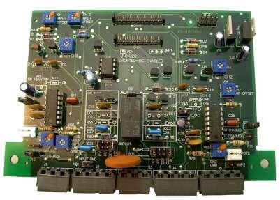
14 The CCPIP Input Card Channel One Controls HD1 J10 When open provides ground lift from chassis. Provides AC coupling when open and DC coupling when shorted. J11-12 Provides ability to enable or disable the front level controls. (populate only one never both) VR1 VR3 VR8 VR10 JMPCC1 Adjusts DC offset of Channel 1 of input card (measured at Pin 1 of U4) Adjusts the Channel 1 soft clip circuit: ~ 15V (CW) No Clip ~8V (Center) Minimum Clip 0V (CCW) Max. Clip Adjusts common mode rejection for balanced input on Channel 1. Adjusts DC offset of Channel 1 of amplifier (measured at output of amplifier). Should be adjusted if gain of amplifier is changed. CV - Puts Channel 1 in Constant Voltage Mode CC - Puts Channel 1 in Constant Current Mode (CC or CV must be jumped for channel to operate) CC1 - Constant Current compensation 1 for Channel 1 connects C 23 and R55 CC2 - Constant Current compensation 2 for Channel 1 connects C27 and R59 NOTE: C18 (Ch.1) C19 (Ch.2) - In parallel with compensation, controls stability and bandwidth when in Constant Current Mode Page 14
15 The CCPIP Input Card Channel 2 Controls: J20 Provides AC coupling when open and DC coupling when shorted. J21-22 Provides ability to enable or disable the front level controls. (populate only one never both) VR2 VR4 VR6 VR9 JMPCC2 Adjusts DC offset of Channel 2 of input card. (measured at Pin 1 of U5) Adjusts the Channel 1 soft clip circuit: ~ 15V (CW) No Clip ~8V (Center) Minimum Clip 0V (CCW) Max. Clip Adjusts DC offset of Channel 2 of amplifier (measured at output of amplifier). Should be adjusted if gain of amplifier is changed. Adjusts common mode rejection for balanced input on Channel 2. CV - Puts Channel 2 in Constant Voltage Mode CC - Puts Channel 2 in Constant Current Mode (CC or CV must be jumped for channel to operate) CC1 - Constant Current compensation 1 for Channel 2 connects C24 and R53 CC2 - Constant Current compensation 2 for Channel 2 connects C26 and R61 Page 15
16 Installation This section describes general guidelines for installing the Model LVC 5050 amplifier with special emphasis on system installations. Unpacking Every AE TECHRON Model LVC 5050 is carefully inspected and tested prior to leaving the factory. Carefully unpack and inspect the unit for damage in shipment. Besides the amplifier, you should find this manual and mounting hardware in the package. 1) Inspect the crating for ANY signs of damage. a. Make written notes of any damage for future reference. b. If damage is found notify the transportation company immediately c. Save the shipping carton and packing materials as evidence of damage for the shipper's inspection. d. If severe damage is apparent, DO NOT proceed until a representative of the shipping company is present. 2) Uncrate/unpack the amplifier 3) Save the packing materials for later use in transporting or shipping the unit. AE TECHRON will cooperate fully in the case of any shipping damage investigation. In any event, replacement-packing materials are available from AE TECHRON. NOTE: Never ship this unit without proper packaging. Page 16

17 Mounting The LVC 5050 is designed for standard 19-inch (48.3 cm) rack mounting and "stack" mounting without a cabinet. For optimum cooling and rack support, multiple units should be stacked directly on top of each other. To reduce the risk of ELECTRIC SHOCK or FIRE HAZARD, DO NOT expose the LVC5050 to rain or moisture. Page 17
 per minute per unit.")
18 Cooling NEVER block the air vents in the front or back of the amplifier. These amplifiers DO NOT need to be mounted with space between them. If you must leave open spaces in a rack for any reason, close them with blank panels or poor airflow will result. Allow for airflow of at least 75 cubic feet (2.1 cubic meters) per minute per unit. Additional airflow may be required when driving low-impedance loads at consistently high output levels. NOTE: Refer to Section 3 Applications for detailed information on thermal dissipation. When mounting the amplifier in a rack cabinet, the back wall of the rack should be at least 3 inches (7.6 cm) away from the back of the amplifier chassis as shown below. If your rack has a door, provide adequate airflow by installing a grille in the door or by pressurizing the air behind the door. Wire grilles are recommended over perforated panels. A good choice for pressurizing the air behind the rack cabinet door is to mount a "squirrel cage" blower inside the rack (Option 1 above). Mount the blower so it blows outside air into the space between the door and front of the amplifiers, pressurizing the chimney" behind the door. This blower should not blow air into or take air out of the space behind the amplifiers. Page 18
19 Making Connections Before beginning the installation of your amplifier, check the following: Remove all power from the unit. Do not have the AC cord plugged in. Turn input level control down (fully counter clockwise). The input and output jacks are located on the back panel. Use care in making connections, selecting signal sources, and matching loads. During hookup take the following precautions: 1. Use only shielded cable on inputs. The higher the density of the shield (the outer conductor), the better the cable. Spiral wrapped shield is not recommended. 2. The output wire and connectors should be heavy enough to carry the intended current to the load. 3. Use good quality connectors with proper strain relief. Do not use connectors that have any tendency to short circuit. Do not use connectors that can be plugged into AC power receptacles. 4. Keep unbalanced input cables as short as possible. Avoid lengths greater than 10 feet. 5. Do not run signal (input) cables together with high level wiring such as load (output) wires or AC cords (lowers most hum and noise). 6. Do not short the ground lead of an output cable to the input signal ground. Oscillations may result. 7. Operate the amplifier from proper AC current. Supply voltage must be 50 to 60 Hz and no more than 10% above or below the selected line voltage. Failure to comply with these frequency limits may damage the unit and result in unreliable operation. Page 19

20 8. Never connect the output to a power supply output, battery, or power main. These connections will cause serious damage to the amplifier. 9. Do not permit unqualified personnel to tamper with circuitry. Do not make unauthorized circuit modifications. Serious damage to the amplifier and/or safety hazards may result. Page 20
21 Dual Channel Hookup In Dual Mode, installation is very intuitive: input Channel 1 feeds output Channel 1, and input Channel 2 feeds output Channel 2. To activate Dual mode: 1. Turn off the amplifier 2. Wait 10 seconds for the power supply to discharge 3. Slide the Dual/Mono switch to the center position 4. Connect the output wiring as shown below. The high-current output block has three sets of output connectors per channel so multiple loads can be easily connected. Two sets accept banana plugs, while the third set accepts spade lugs or bare wire. Observe correct load polarity and be very careful not to short the two outputs. Page 21
22 Bridge-Mono Hookup Bridge-Mono mode is intended for driving loads with a total impedance of 4 ohms or more (see Section if the load is less than 4 ohms). Installing the amplifier in Bridge-Mono mode is very different from the other modes and requires special attention. To activate Bridge-Mono mode: 1. Turn the amplifier off 2. Wait at least 10 seconds 3. Slide the Dual/Mono switch to the right (as you face the back of the amplifier). NOTE: Both outputs receive the signal from the channel 1 input with the output of channel 2 inverted so it can be bridged with the channel 1 output. AND NOTE: The channel 2 input and level control are disconnected in Bridge Mono mode. A signal-feeding channel 2 will have no effect on the output. 1. Connect the load across the channel 1 and 2 positive (+) terminals 2. Attach the positive lead from the load to channel Attach the negative lead from the load to channel 2. (This cannot be connected to ground, chassis or amplifier, or it will damage the amplifier. The negative (-) terminals are not used and should not be shorted. This cannot be connected to ground, chassis or amplifier, it will damage the amplifier. Page 22
23 Parallel-Mono Hookup Parallel-Mono mode is intended for driving loads with a total impedance of less than 4 ohms (see Section if the load is 4 ohms or greater). Installing the amplifier in Parallel-Mono mode is very different from the other modes and requires special attention. To activate Parallel-Mono mode: 1. Turn off the amplifier 2. Wait at least 10 seconds 3. Slide the Dual/Mono switch to the left (as you face the back panel). 4. Connect the input signal to channel 1, and do not use the channel 2 input Both outputs will now receive the signal from the channel 1 input. NOTE: The channel 2 input and level control are disconnected in Parallel-Mono mode. A signal-feeding channel 2 will have no effect on the output. To complete connections: 1. Install a jumper wire between the positive (+) outputs of channel 1 and 2 that is at least 14 gauge in size. 2. Connect the load to the output of channel 1 as shown below. 3. Connect positive (+) lead from the load to the positive (+) channel 1 terminal 4. Connect the negative (-) lead from the load to the negative (-) channel 1 terminal. Channel 2 s Green LED will be bright this is normal. NOTE: Remember to remove the jumper between the positive output terminals before changing to Bridge-Mono or Dual modes Amplifier damage may result. Page 23
24 Connecting Power The LVC 5050 uses a 3-wire (grounded) AC line system. At times, the third wire ground may introduce a ground loop into the system. Each LVC 5050 is supplied from the factory with an appropriate AC cord. Units set up for 100 to 120 VAC operation is shipped with 10 AWG, 30 amp line cords. Units set up for 200 to 240 VAC operation is shipped with 12 AWG, 20 amp line cords. North American units set up for 120 VAC, 60 Hz operation are provided with a 125 volt, 30 amp NEMA TT30P plug. Units destined for other parts of the world are provided without a plug. Whenever possible, connect the power cord to an isolated power circuit with adequate current. Excessive line voltages of more than 11% above the amplifier's rated line voltage will activate the overvoltage protection circuitry. All specifications in this manual were measured using 120 VAC, 60 Hz power mains unless otherwise noted. Specifications are derived using a peak main voltage equal to the true peak of a 120 V RMS sine wave with all available channels fully loaded. Although this amplifier is rated for operation at 100 and 120 VAC, it is more efficient at 200, 208, 230 or 240 VAC. At these higher voltages, less power is converted to thermal energy in the AC cord and slightly more power is available at low frequencies. Page 24
Technical Manual LVC5050. Power Supply Amplifier
 Technical Manual LVC5050 Power Supply Amplifier LVC5050 Power Supply Amplifier Technical Manual AE TECHRON 2002 2507 Warren St. Elkhart IN 46516 U.S.A. Phone: (574) 295-9495 Fax: (574) 295-9496 E-Mail:
SAGA PRO SERIES STEREO POWER AMPLIFIER OPERATION MANUAL
 SAGA PRO SERIES STEREO POWER AMPLIFIER OPERATION MANUAL INSTALLATION Use care in unpacking the amplifier, and be sure to save the carton and packing materials so that you can use them for moving, storing,
PROFESSIONAL POWER AMP
 Operating Instruction Manual PROFESSIONAL POWER AMP Model P-75D, P-150D, P-300D P-75D P-150D P-300D TOA Corporation KOBE, JAPAN Contents Precautions... 1 General Description... 2 Features... 2~ 3 Specifications...
8101 SPECIFICATION SHEET
 2 5 0 7 W a r r e n S t r e e t, E l k h a r t, I N 4 6 5 1 6 U S A 5 7 4. 2 9 5. 9 4 9 5 w w w. A E T e c h r o n. c o m The AE Techron 8101 power supply amplifier features an advanced switchmode design
TOA PROFESSIONAL POWER AMP
 Operating Instruction Manual TOA PROFESSIONAL POWER AMP Model P-150M, P-300M TOA ELECTRIC CO, LTD. KOBE, JAPAN Contents Precautions... 2 General Description... 2 Features... 3 Specifications... 4~5 Performance
American Audio. User Instructions. American Audio 4295 Charter Strret Los Angeles Ca Revised 5/01
 American Audio User Instructions American Audio 4295 Charter Strret Los Angeles Ca. 90058 Revised 5/01 CAUTION Do not open - risk of electric shock CAUTION: TO REDUCE THE RISK OF ELECTRIC SHOCK, DO NOT
Amplifier Series BASIC. Installation & Operations Manual
 Amplifier Series BASIC Installation & Operations Manual Bittner-Audio 200 Power Amplifier Series BASIC Bittner - Audio September 200 200 Bittner-Audio. All Rights Reserved. Bittner-Audio reserves specification
Model Quality in Test and Measurement Since 1949 OUTSTANDING PERFORMANCE DESCRIPTION APPLICATIONS ADDITIONAL FEATURES
 Quality in Test and Measurement Since 1949 DC Source/Calibrators, Tunable Electronic Filters, Wideband Power Amplifiers Precision Phasemeters, Distortion Analyzers Function Generators, RC Oscillators Model
The ART SLA-2 Studio Linear Amplifier
 TABLE OF CONTENTS The ART SLA-2 Studio Linear Amplifier Safety Precautions... 2-3 Introduction... 4 Installation... 5 AC Power Hookup... 5 Audio Connections... 5 Security Cover... 6 Controls and Indicators...
Professional Power Amplifier
 SERVICE FOR YOURCBU PRODUCT (International) For service, please contact the CBU distributor in your country through the dealer from whom you purchased this product. DO NOT ATTEMPT TO SERVICE THIS UNIT
STEREO POWER AMPLIFIER OWNER MANUAL PR-150 DESIGNED IN U.K. PDF created with FinePrint pdffactory trial version
 STEREO POWER AMPLIFIER OWNER MANUAL PR-150 DESIGNED IN U.K. INTRODUCTION Congratulations on your purchase of MA PR-150 Stereo Power Amplifier. The performance of PR-150 is perfect for any audio application,
Owner s Manual B 300 B 600 B 900 B 1200 B 1500 B 902 B 1202 B 1802 B300 B1802
 Owner s Manual B 300 B 600 B 900 B 1200 B 1500 B300 B 902 B 1202 B 1802 B1802 WARNING B 300 / B 600 / B 900 / B 1200 / B 1500 / B 902 / B 1202 / B 1802 Table of Contents Table of Contents Introduction
Model Operating Manual
 Model 7500 DC to 1MHz Wideband Power Amplifier Operating Manual Copyright 2004. All rights reserved. Contents of this publication may not be reproduced in any form without the written permission of Krohn-Hite
Model 7000 Low Noise Differential Preamplifier
 Model 7000 Low Noise Differential Preamplifier Operating Manual Service and Warranty Krohn-Hite Instruments are designed and manufactured in accordance with sound engineering practices and should give
DPA-1200 ORDERCODE D4180 DPA-2400 ORDERCODE D4181 DPA-3400 ORDERCODE D4182
 Digital DPA-1200 DPA-2400 DPA-3400 ORDERCODE D4180 ORDERCODE D4181 ORDERCODE D4182 Congratulations! You have bought a great, innovative product from DAP Audio. The Dap Audio Vintage Digital Power Series
POWER AMPLIFIER. Owner s Manual Mode d emploi Bedienungsanleitung Manual de instrucciónes CLIP SIGNAL TEMP PROTECTION POWER
 POWER AMPLIFIER Owner s Manual Mode d emploi Bedienungsanleitung Manual de instrucciónes TEMP PROTECTION POWER A CLIP SIGNAL B ON OFF M Introduction Thank you for purchasing a Yamaha C450/320/160 series
MZ2 HEADPHONE AMPLIFIER, PREAMP, & STEREO AMPLIFIER USER GUIDE
 MZ2 HEADPHONE AMPLIFIER, PREAMP, & STEREO AMPLIFIER USER GUIDE Linear Tube Audio Takoma Park, MD, USA WARNING: For safety, the cover of this amplifier should be secured at all times. DC voltages as high
USER MANUAL MG-TA1000 POWER AMPLIFIER
 USER MANUAL MG-TA1000 POWER AMPLIFIER INDEX: INTRODUCTION SAFETY INSTRUCTIONS OPERATING PRECAUTIONS FEATURES OF PANAL CONTROLS FRONT & REAR PPANEL DISPLAY CONNECTING INPUTS SPEAKER CONNECTIONS INTRODUCTION:
A 4000 A Owner s Manual HPA HPA A4000 A5000 PROFESSIONAL POWER AMPLIFIER POWER CHANNEL 2 CHANNEL 1 PROFESSIONAL POWER AMPLIFIER POWER CHANNEL 2
 Owner s Manual A 000 A 000 PROFESSIAL POWER AMPLIFIER CHANNEL POWER PROTECT CLIP -0dB -0dB SIGNAL ACTIVE A000 CHANNEL HPA 0 9 0 9 9 0 9 0 9 9 PROFESSIAL POWER AMPLIFIER CHANNEL POWER PROTECT CLIP -0dB
IMPORTANT SAFETY INSTRUCTIONS
 IMPORTANT SAFETY INSTRUCTIONS When using this electronic device, basic precautions should always be taken, including the following: 1. Read all instructions before using the product. 2. Do not use this
Owner s Manual.
 P Z R 6 0 0 A m p l i f i e r P Z R 1 0 0 0 A m p l i f i e r Owner s Manual www.pyleaudio.com Your New Pyle Pro PZR series P.A. Amplifier gives you the power and versatility you need in a professional
a315 power amplifier Owner s Manual
 Wadia Digital, LLC. 2 Chambers Street Binghamton, New York 13903-2699 Phone: 607-723-3539 Fax: 607-724-0549 www.wadia.com a315 power amplifier Owner s Manual 2 The lightning flash with arrowhead, within
AV30MX-2 Operation Manual
 AV30MX-2 Operation Manual 1 Important safety instructions 1. Please read carefully prior to product installation or operation. 2. Read these instructions. 3. Keep these instructions. 4. Heed all warnings.
CX-A6 Amplifier Installation & User Guide V8.0
 CX-A6 Amplifier Installation & User Guide V8.0 Cloud Electronics Limited 140 Staniforth Road, Sheffield, S9 3HF England Tel + 44 (0) 114 244 7051 Fax + 44 (0) 114 242 5462 E-mail info@cloud.co.uk Web site
MC450/MC650 (MC750) OPERATING INSTRUCTIONS
 OPERATING INSTRUCTIONS") MC450/MC650 (MC750) OPERATING INSTRUCTIONS MC 2 AUDIO Ltd., Units 6 & 7 Kingsgate, Heathpark Industrial Estate, HONITON, Devon EX14 1YG England Tel: ++(0)1404.44633 Fax: ++(0)1404.44660 www.mc2-audio.co.uk
MC450/MC650 (MC750) OPERATING INSTRUCTIONS MC 2 AUDIO Ltd., Units 6 & 7 Kingsgate, Heathpark Industrial Estate, HONITON, Devon EX14 1YG England Tel: ++(0)1404.44633 Fax: ++(0)1404.44660 www.mc2-audio.co.uk
POWER AMPLIFIER. Owner s Manual POWER AMPLIFIER R 20 CLIP POWER TEMP PROTECTION 6 POWER. Keep This Manual For Future Reference.
 POWER AMPLIFIER Owner s Manual POWER AMPLIFIER POWER 20 5 L CLIP R 20 5 TEMP 25 0 25 0 PROTECTION 0 LEVEL 0 6 6 POWER 40 40 ON OFF L 0 db R 0 Keep This Manual For Future Reference. E WARNING: THIS APPARATUS
TOA NEW 900 SERIES MIXER PREAMPLIFIER M-900A
 Operation Instruction Manual TOA NEW 900 SERIES MIXER PREAMPLIFIER M-900A Features General Description 1 6-channel mixer preamplifier 2 Wide frequency response; 20 20,000Hz, ±1dB 3 Low distortion and noise
IP Series DUAL POWER AMPLIFIERS
 OPERATING INSTRUCTIONS IP Series DUAL POWER AMPLIFIERS IP-600D IP-450D IP-300D TABLE OF CONTENTS 1. SAFETY PRECAUTIONS... 2 2. GENERAL DESCRIPTION... 4 3. FEATURES... 4 4. HANDLING PRECAUTIONS... 4 5.
USER MANUAL VIVALDI MZ550A. Distribution Mixer Amplifier
 USER MANUAL VIVALDI MZ550A Distribution Mixer Amplifier 1. Security Precautions Carefully READ the instruction in this manual before use. Be sure to OBSERVE the INSTRUCTION in this manual regard convention
MODEL W Power Amplifier
 TEGAM, INC. MODEL 2348 18.75 W Power Amplifier This owner s manual was as current as possible when this product was manufactured. However, products are constantly being updated and improved. Because of
SI-125 Power Amplifier Manual 6205 Kestrel Road; Mississauga, Ontario; Canada; L5T 2A1 November 2016, Rev 0.5
 SI-125 Power Amplifier Manual 6205 Kestrel Road; Mississauga, Ontario; Canada; L5T 2A1 November 2016, Rev 0.5 Phone: (905) 564-0801 Fax: (905) 564-0806 www.telecor.com E:\T2-108\T2-M108-ABC\T2-M108-B.doc/AD
MC75 Tube Power Amplifier Owner s Manual
 McIntosh Laboratory, Inc. 2 Chambers Street Binghamton, New York MC75 Tube Power Amplifier Owner s Manual 13903-2699 Phone: 607-723-3512 www.mcintoshlabs.com 2 The lightning flash with arrowhead, within
CX-A6 Amplifier Installation & User Guide V9.0
 CX-A6 Amplifier Installation & User Guide V9.0 Cloud Electronics Limited 140 Staniforth Road, Sheffield, S9 3HF England Tel + 44 (0) 114 244 7051 Fax + 44 (0) 114 242 5462 E-mail info@cloud.co.uk Web site
Opus 21 s80 Integrated Amplifier Owner's Manual
 Opus 21 s80 Integrated Amplifier Owner's Manual r e s o l u t i o n From all of us at Resolution Audio, thank you for choosing the Opus 21 s80 amplifier. We went to great lengths to design and produce
AV Series AV-25-2 AV-25 Owner s Manual February 2010
 AV Series AV-25-2 AV-25 Owner s Manual February 2010 www.stewartaudio.com Important Safety Instructions Before using your Stewart Audio Inc. Power Amplifier, please read this Owner s Manual carefully to
TA 450 MK-X TA 600 MK-X TA 1050 MK-X TA 1400 MK-X TA 2400 MK-X power amplifier. user manual
 TA 450 MK-X TA 600 MK-X TA 1050 MK-X TA 1400 MK-X TA 2400 MK-X power amplifier user manual Musikhaus Thomann e. K. Treppendorf 30 96138 Burgebrach Germany Telephone: +49 (0) 9546 9223-0 E-mail: info@thomann.de
MODEL 3 MONO AMPLIFIER OWNER S MANUAL
 MODEL 3 MONO AMPLIFIER OWNER S MANUAL TABLE OF CONTENTS Introduction Features Unpacking Instructions Installation * Space requirements * A.C. connections Input Impedance Selection Adjustable Gain Signal
AV25-2 User Manual. 1 Important safety instructions
 AV25-2 User Manual 1 Important safety instructions 1. Please read carefully prior to product installation or operation. 2. Read these instructions. 3. Keep these instructions. 4. Heed all warnings. 5.
GUITAR POWER AMPLIFIER U S E R ' S M A N U A L
 GUITAR POWER AMPLIFIER U S E R ' S M A N U A L May be covered by one or more of the following: U.S. Patents #4538297, 4647876, 4696044, 4745309, 4881047, 4893099, 5124657, 5263091, 5268527, 5319713 and
TOA 500 SERIES MIXER POWER AMPLIFIER
 TOA 500 SERIES MIXER POWER AMPLIFIER Operation Instruction Manual A-503A A-506A A-512A Features General Description 1. High quality design and construction. 2. Full frequency response: 50-15,000Hz, ±3dB.
TOA 900 SERIES POWER AMPLIFIER P-924A
 Operation Instruction Manual TOA 900 SERIES POWER AMPLIFIER P-924A Features General Descriptions 1 Wide frequency response; 20 20,000 Hz, ±1dB 2 Low distortion and noise level 3 Excellent output regulation
MC2301. Features and Benefits. Promotional Highlights TUBE POWER AMPLIFIER MCINTOSH LABORATORY INC., 2 CHAMBERS STREET, BINGHAMTON, NEW YORK 13903
 MC2301 Product Preview Page 1 McIntosh Laboratory, Inc., Binghamton, NY 13903 Design Engineering Department PRODUCT PREVIEW MC2301 TUBE POWER AMPLIFIER Project 1336 Promotional Highlights 300 Watts Mono
HTA125A/250A. Power Amplifiers. Installation & Use Manual
 HTA125A/250A Power Amplifiers Installation & Use Manual Specifications subject to change without notice. 2010 Bogen Communications, Inc. All rights reserved. 54-5832-04B 1011 NOTICE: Every effort was made
Audio Amplifiers for Professional Applications. Face Audio Owner's Manual for TS Series Amplifiers
 Audio Amplifiers for Professional Applications. Face Audio Owner's Manual for TS Series Amplifiers 8675 South Sandy Parkway Building 110 Sandy, Utah 84070 Toll Free (877) 5251163 www.faceaudio.com 8675
PROFESSIONAL POWER AMPLIFIERS. User Instructions. American DJ V3000 LIMITER. American DJ LIMITER I LIMITER. ON channel 2
 & PROFESSIONAL POWER AMPLIFIERS User Instructions American DJ SIG 20 10 5 CLIP PROTECT POWER PROTECT CLIP 5 10 20 SIG PROformer Series V3000 channel 1 ON ON channel 2 I O Professional Stereo Amplifier
PagePac Plus AmpliCenter V /V /V
 PagePac by ISSUE PagePac Plus AmpliCenter V53800V538100V538300 Installation and Use 919 AmpliCenter D300 Installation Steps Note: If installed next to other equipment including the PagePac Plus Controller
Operating Instruction Manual ELECTRONIC MUSIC AMPLIFICATION SYSTEM. Model KD-1. Toa Electric Co., Ltd. KOBE, JAPAN
 Operating Instruction Manual ELECTRONIC MUSIC AMPLIFICATION SYSTEM Model KD-1 Toa Electric Co., Ltd. KOBE, JAPAN Contents Precautions... 1 General Description... 2 Features... 2 Front Panel: Names of components
REVAMP2250 Instruction manual
 REVAMP2250 Instruction manual REVAMP2250 Instruction manual 3 REVAMP2250 Manual 4 DIGITAL POWER AMPLIFIER Safety first! Caution! This professional device needs to be installed by qualified personnel only.
CMP-300 Composite Mixer/ Distribution Amplifier
 Broadcast Devices, Inc. CMP00 Composite Mixer/ Distribution Amplifier TECHNICAL REFERENCE MANUAL Broadcast Devices, Inc. Crestview Avenue Cortlandt Manor, NY 0 Tel. (9) 0 Fax. (9) 9 REV: A 0/0 Table of
DX 48 DX 24 DX 12 D X - S e r i e s
 DX 48 DX 24 DX 12 D X - S e r i e s The CAMCO DX-Series power amps have been designed to comply with the international industrial standard that finds worldwide application. The DX Series sets new standards
léìë=on ëpm=fåíéöê~íéç=^ãéäáñáéê lïåéêdë=j~åì~ä êéëçäìíáçå
 léìë=on ëpm=fåíéöê~íéç=^ãéäáñáéê lïåéêdë=j~åì~ä êéëçäìíáçå From all of us at Resolution AV, thank you for choosing the Opus 21 s30 amplifier. We went to great lengths to design and produce an integrated
R-Series R235LS 2-Channel Power Amplifier with Local Source Switching
 R-Series R235LS 2-Channel Power Amplifier with Local Source Switching User s Manual On Off R235LS POWER A MPLIFIER IMPORTANT SAFEGUARDS WARNING TO REDUCE THE RISK OF FIRE OR ELECTRIC SHOCK, DO NOT EXPOSE
PARALLEL MULTI-AMP KIT for 7200 Series AMPLIFIERS INSTRUCTION SHEET
 2 5 0 7 W a r r e n S t r e e t, E l k h a r t, I N 4 6 5 1 6 U S A 5 7 4. 2 9 5. 9 4 9 5 w w w. A E T e c h r o n. c o m PARALLEL MULTI-AMP KIT for 7200 Series AMPLIFIERS INSTRUCTION SHEET Kit Contents:
Studio MODEL:PA600X/PA800X/PA1000X/ PA1800X PA AMPLIFIER PRO. High Performance Professional Audio.
 Studio PRO High Performance Professional Audio MODEL:PA600X/PA800X/PA1000X/ PA1800X PA AMPLIFIER www.pyramidcaraudio.com INTRODUCTION Your New PYRAMID PA SERIES AMPLIFIER gives you the power and versatility
2BSST POWER AMPLIFIER OWNER S MANUAL
 2BSST POWER AMPLIFIER OWNER S MANUAL IMPORTANT SAFETY INSTRUCTIONS The lightning flash with arrowhead symbol within an equilateral triangle, is intended to alert the user to the presence of un-insulated
POWERFUL RELIABLE VERSATILE THE NO.1 CHOICE IN PROFESSIONAL AMPLIFICATION
 CRO-TECH SERIES VERSATILE RELIABLE POWERFUL THE NO.1 CHOICE IN PROFESSIONAL AMPLIFICATION THE ULTITE AMP, PERIOD CRISP ADVANTAGES The Crown Macro-Tech Series is the defining standard for amplifier design
M-300 Mono power amplifier User s guide
 M-300 Mono power amplifier User s guide M-300 Mono power amplifier User s guide Specifications: Contents: Power output: 8Ω: 290W, 0.01% THD SPECIFICATIONS Page 2 Input impedance: Gain: 4Ω: 580W, 0.01%
plifier D-501 otion Am Tactile M
 Tactile Motion Amplifier D-501 IMPORTANT SAFETY INSTRUCTIONS WARNING: 1. Read and keep these instructions for future reference. 2. Do not use this apparatus near water. 3. Clean only with a dry cloth.
1160 Stereo Power Amplifier
 1160 Stereo Power Amplifier 03/01/2018 Rev. 1.0 P/N: 91055 Boulder Amplifiers, Inc. 255 S. Taylor Ave. Louisville, CO 80027 (303) 449-8220 www.boulderamp.com About About Boulder Amplifiers, Inc. Boulder
ZOTL40 Mk.II POWER AMPLIFIER USER GUIDE. Linear Tube Audio Takoma Park, MD, USA
 ZOTL40 Mk.II POWER AMPLIFIER USER GUIDE Linear Tube Audio Takoma Park, MD, USA WARNING: For safety, the cover of this amplifier should be secured at all times. DC voltages as high as 1000V and peak AC
AW 2x120 BALANCED POWER AMPLIFIER
 AW 2x120 BALANCED POWER AMPLIFIER Owner s Manual WARNING: To reduce risk of fire or electric shock, do not expose this appliance to rain or moisture. Verify line voltage before use. Do not remove cover.
Q-Tech. Q-Tech Commercial Series QTA 1360P/1480P Power Amplifiers. User Manual
 Q-Tech Power Amplifiers WARNING THIS APPLIANCE MUST BE EARTHED General Installation DO NOT run unbalanced high impedance microphone cables near mains, data, telephone or 70/100V line cables. DO NOT run
Owner s Manual QA4150 QA4300 HPA HPA QA4150 QA4300 POWER QUAD-CHANNEL POWER AMPLIFIER CHANNEL 4 CHANNEL 1 CHANNEL 2 CHANNEL 3 POWER QUAD-CHANNEL
 Owner s Manual Q Q POWER MPLIFIER QUD-CHNNEL POWER ON OFF Q HP CHNNEL PROTECT CLIP SIGNL CHNNEL PROTECT CLIP SIGNL CHNNEL PROTECT CLIP SIGNL CHNNEL PROTECT CLIP SIGNL POWER MPLIFIER QUD-CHNNEL POWER ON
forte Owner s Manual
 forte Owner s Manual Table of Contents Important Safety Instructions... 3 Introduction... 4 Quick Start... 5 Front Panel Controls and Operation... 6 Rear Panel Controls and Operation... 8 Installation
TSA 4-700, TSA 1400, TSA 2200, TSA 4000, TSA 4-300, TSA power amplifier. user manual
 TSA 4-700, TSA 1400, TSA 2200, TSA 4000, TSA 4-300, TSA 4-1300 power amplifier user manual Musikhaus Thomann e. K. Treppendorf 30 96138 Burgebrach Germany Telephone: +49 (0) 9546 9223-0 E-mail: info@thomann.de
Power Amplifier. MC252 Owner s Manual
 Power Amplifier MC252 Owner s Manual McIntosh Laboratory, Inc. 2 Chambers Street Binghamton, New York 13903-2699 Phone: 607-723-3512 FAX: 607-724-0549 The lightning flash with arrowhead, within an equilateral
AV Series AV30MX-2 AV30MX-2 Owner s Manual October 2010
 AV Series AV30MX-2 AV30MX-2 Owner s Manual October 2010 www.stewartaudio.com Important Safety Instructions Before using your Stewart Audio Inc. Power Amplifier, please read this Owner s Manual carefully
OWNER S MANUAL CPS 1 / CPS 2 CONTRACTOR PRECISION SERIES
 OWNER S MANUAL CPS 1 / CPS 2 CONTRACTOR PRECISION SERIES CONTENTS Introduction................................................................... 9 Front Panel...................................................................
PagePac Plus AmpliCenter V A - (D300A) V A - (D100A) V (D40) Installation and Use
 V A - (D100A) V (D40) Installation and Use") Issue 3 IMPORTANT SAFETY INFORMATION: PagePac Plus AmpliCenter V-5328300A - (D300A) V-5328100A - (D100A) V-5328040 - (D40) Installation and Use 1. Read these instructions. 2. Keep these instructions. 3.
Issue 3 IMPORTANT SAFETY INFORMATION: PagePac Plus AmpliCenter V-5328300A - (D300A) V-5328100A - (D100A) V-5328040 - (D40) Installation and Use 1. Read these instructions. 2. Keep these instructions. 3.
MC312 Power Amplifier Owner s Manual
 McIntosh Laboratory, Inc. 2 Chambers Street Binghamton, New York MC312 Power Amplifier Owner s Manual 13903-2699 Phone: 607-723-3512 www.mcintoshlabs.com Important Safety Information is supplied in a separate
HQ-31 HQ-15 USER S GUIDE SINGLE CHANNEL 31 BAND 1/3 OCTAVE GRAPHIC EQUALIZER DUAL CHANNEL 15 BAND 2/3 OCTAVE GRAPHIC EQUALIZER
 HQ-31 SINGLE CHANNEL 31 BAND 1/3 OCTAVE GRAPHIC EQUALIZER HQ-15 DUAL CHANNEL 15 BAND 2/3 OCTAVE GRAPHIC EQUALIZER USER S GUIDE GENERAL INFORMATION SINGLE CHANNEL 31 BAND 1/3 OCTAVE GRAPHIC EQUALIZER WITH
REVAMP2600 Instruction manual
 REVAMP2600 Instruction manual REVAMP2600 Instruction manual 3 REVAMP2600 MANUAL 4 PROFESSIONAL POWER AMPLIFIER Safety first! Caution! This professional device needs to be installed by qualified personnel
Instruction Kit MIXER AMPLIFIER GT 60C GT 125C. GROMMES-PRECISION SINCE-46
 Instruction Kit GT 60C GT 125C MIXER AMPLIFIER GROMMES-PRECISION 1-800-SINCE-46 www.grommesprecision.com Thank you for purchasing from Grommes~Precision! Grommes~Precision and its commercial audio division,
MANUAL. Champ - 4. Professional quad power amplifier
 MANUAL Champ - 4 Professional quad power amplifier INFO@APART-AUDIO.COM Safety First! Caution: hot and sharp surfaces! This professional device needs to be installed by qualified personnel only. Please
3BSST 4BSST POWER AMPLIFIER OWNER S MANUAL UPDATED
 3BSST 4BSST POWER AMPLIFIER OWNER S MANUAL UPDATED 007-01-9 3Bsst & 4Bsst POWER AMPLIFIERS GENERAL INFORMATION Introduction Thank you for choosing an SST SERIES Stereo Power Amplifier. Bryston welcomes
Model Hz to 10MHz Precision Phasemeter. Operating Manual
 Model 6610 1Hz to 10MHz Precision Phasemeter Operating Manual Service and Warranty Krohn-Hite Instruments are designed and manufactured in accordance with sound engineering practices and should give long
PagePac Plus AmpliCenter V A/V A Installation and Use
 Issue 1 Important Safety Instructions PagePac Plus AmpliCenter V-5328100A/V-5328300A Installation and Use 1. Read these instructions. 2. Keep these instructions. 3. Heed all warnings. 4. Follow all instructions.
TOA NEW 900 SERIES MIXER POWER AMPLIFIER A-901A. General Description. TOA Corporation. Operation Instruction Manual
 Operation Instruction Manual TOA NEW 900 SERIES MIXER POWER AMPLIFIER A-901A Features 1 3-channel mixer power amplifier 2 Wide frequency response; 20 20,000 Hz, ±1dB 3 Low distortion and noise level 4
E4-130, E4-250 power amplifier. user manual
 E4-130, E4-250 power amplifier user manual Musikhaus Thomann e.k. Treppendorf 30 96138 Burgebrach Germany Telephone: +49 (0) 9546 9223-0 E-mail: info@thomann.de Internet: www.thomann.de 30.10.2014, ID:
Please Read First. Safety Instructions WARNING: TO REDUCE THE RISK OF FIRE OR ELECTRIC SHOCK, DO NOT EXPOSE THIS UNIT TO RAIN OR MOISTURE.
 Please Read First CAUTION: To reduce the risk of electrical shock, do not remove the cover (or back). No user serviceable parts inside. Refer servicing to qualified service personnel. WARNING: To reduce
Professional Stereo Amplifiers
 Symbol 12000 Professional Stereo Amplifiers ENGLISH FBT elettronica S.p.A. - Via Paolo Soprani 1 - Zona Ind.le Squartabue - 62019 RECANATI (MC) - ITALY TEL. 071/750591 r.a. - FAX 071/7505920 - http://www.fbt.it
PROFESSIONAL STEREO AMPLIFIERS USER GUIDE
 PROFESSIONAL STEREO AMPLIFIERS USER GUIDE 967/9673 - September 00 - Version.0 ENGLISH Ti SERIES - Professional stereo amplifiers Page Ti SERIES - Professional stereo amplifiers ENGLISH - Safety information
DPA74/154 AUDAC PROFESSIONAL AUDIO EQUIPMENT. DPA74/154 Quad Channel Class-D Amplifier. User Manual & Installation Guide
 DPA74/154 PROFESSIONAL AUDIO EQUIPMENT DPA74/154 Quad Channel Class-D Amplifier AUDAC User Manual & Installation Guide AUDAC PROFESSIONAL AUDIO EQUIPMENT User Manual & Installation Guide AUDAC http://www.audac.eu
DPA602 1/7. Multi-Channel Network Amplifier. General Description. Features. Applications. AtlasIED.com. DPA602 Front. DPA602 Back
 1/7 DPA602 Multi-Channel Network Amplifier Features Configurations 2 x 300 Watt 70V / 100V (Factory Default) 4 x 150 Watt @ 4Ω 1 x 300 Watt 70V / 100V & 2 x 150 Watt @ 4Ω No Computer Required to Operate
PROFESSIONAL SMPS STEREO AMPLIFIERS USER GUIDE
 PROFESSIONAL SMPS STEREO AMPLIFIERS USER GUIDE 987/988/989 - December 00 - Version.0 English SMi series - Professional SMPS stereo amplifiers - Safety information Important safety information This unit
441 DUAL CHANNEL 15 BAND 2/3 OCTAVE GRAPHIC EQUALIZER 451 SINGLE CHANNEL 31 BAND 1/3 OCTAVE GRAPHIC EQUALIZER
 441 DUAL CHANNEL 15 BAND 2/3 OCTAVE GRAPHIC EQUALIZER 451 SINGLE CHANNEL 31 BAND 1/3 OCTAVE GRAPHIC EQUALIZER 455 DUAL CHANNEL 31 BAND 1/3 OCTAVE GRAPHIC EQUALIZER The new ART 400 Series of Precision Graphic
User's Manual PS 2/2A LTO R. Version 1.1 Septemper 2005 English
 User's Manual PS 2/2A LTO R www.altoproaudio.com Version 1.1 Septemper 2005 English SAFETY INSTRUCTIONS CAUTION RISK OF ELECTRIC SHOCK DO NOT OPEN "Electric discharge" This symbol, alert you to the presence
CANARY AUDIO. EL34 Stereo Power Amplifier. Handcrafted in California CA-770 OWNER S MANUAL MADE IN USA
 CANARY AUDIO EL34 Stereo Power Amplifier Handcrafted in California CA-770 OWNER S MANUAL MADE IN USA Dear Customer: Please allow us to take this opportunity to thank you for purchasing this CANARY AUDIO
Model 4402B. Ultra-Pure Sinewave Oscillator 1Hz to 110kHz Typical Distortion of % Serial No. Operating Manual
 Model 4402B Ultra-Pure Sinewave Oscillator 1Hz to 110kHz Typical Distortion of 0.0005% Serial No. Operating Manual 15 Jonathan Drive, Unit 4, Brockton, MA 02301 U.S.A. Tel: (508) 580-1660; Fax: (508) 583-8989
HCA-1000A High Current Power Amplifier HCA-750A High Current Power Amplifier
 O W N E R ' S M A N U A L HCA-1000A High Current Power Amplifier HCA-750A High Current Power Amplifier HCA-1000A High Current Power Amplifier Current Overload L R AC Line Standby Normal HCA-750A High Current
TEGAM, INC. SINGLE/DUAL CHANNEL HIGH VOLTAGE AMPLIFIER MODEL 2340/2350. Instruction Manual PN# CD Publication Date: June 2006 REV.
 TEGAM, INC. SINGLE/DUAL CHANNEL HIGH VOLTAGE AMPLIFIER MODEL 2340/2350 Instruction Manual PN# 810044-CD Publication Date: June 2006 REV. C This owner s manual was as current as possible when this product
MIXER POWER AMPLIFIER BG-130
 OPERATING INSTRUCTIONS MIXER POWER AMPLIFIER BG-115 BG-130 TO REDUCE THE RISK OF ELECTRICAL SHOCK, DO NOT REMOVE COVER. NO USER SERVICEABLE PARTS INSIDE. REFER SERVICING TO QUALIFIED SERVICE PERSONNEL
PowerMatch PM8500 / 8500N TECHNICAL DATA SHEET. configurable power amplifier. Key Features. Product Overview. Applications
 Product Overview Bose PowerMatch PM8500 is a configurable professional power amplifier delivering concert sound quality for fixed installation sound reinforcement systems. Building on the ruggedness proven
DPAfour125, DPAfour250 AMPLIFIERS. Operating Manual
 DPAfour125, DPAfour250 AMPLIFIERS Operating Manual Operating manual, DPA Series DPA-10UMS01-V01R04 version revision date 01 02 24-02-2012 www.ateis-europe.com ATEÏS Europe BV - Sydneystraat 42-3047BP ROTTERDAM
QA SERIES QA 1004 QA 2004 QA 3004 QA POWER AMPLIFIERS user manual
 QA 1004 QA 2004 QA 3004 QA 4004 POWER AMPLIFIERS user manual Contents CONTENTS / SAFETY Safety 02-03 Introduction to 04 Connections 05 Amplifer installation information 06-07 Installation procedure 08-09
MC58 Eight Channel Power Amplifier
 Owner s Manual MC58 Eight Channel Power Amplifier MC58 McIntosh Laboratory, Inc. 2 Chambers Street Binghamton, New York 13903-2699 Phone: 607-723-3512 FAX: 607-724-0549 The lightning flash with arrowhead,
Model: Macro-Tech 3600VZ Some models may be exported under the name Amcron.
 LEVEL LEVEL 15 1 18 9 1 ODEP 15 1 18 9 1 6 7 SIGNAL/IOC 6 7 ON OFF 0 0 CH1 CH 0 0 ENABLE Model: Macro-Tech 600VZ Some models may be exported under the name Amcron. 1997 by Crown International, Inc., P.O.
WRM-10 TM TRANSFORMER WINDING RESISTANCE METER
 WRM-10 TM TRANSFORMER WINDING RESISTANCE METER USER S MANUAL Vanguard Instruments Company, Inc. 1520 S. Hellman Ave. Ontario, California 91761, USA TEL: (909) 923-9390 FAX: (909) 923-9391 June 2009 Revision
MODEL 302IQ (1991-MSRP $149.00)
") F O R T H E L O V E O F M U S I C MODEL 302IQ (1991-MSRP $149.00) OWNER'S MANUAL AND INSTALLATION GUIDE INTRODUCTION Latest technology, high sound quality, powerful delivery, and LINEAR POWER reliability
F O R T H E L O V E O F M U S I C MODEL 302IQ (1991-MSRP $149.00) OWNER'S MANUAL AND INSTALLATION GUIDE INTRODUCTION Latest technology, high sound quality, powerful delivery, and LINEAR POWER reliability
3050 Stereo Power Amplifier
 3050 Stereo Power Amplifier Owners Manual 10/26/2016 Boulder Amplifiers, Inc. 255 Taylor Ave. Louisville, CO 80027 (303) 449-8220 www.boulderamp.com Fault Conditions Boulderlink Appendix Remote Control