Radio Coverage Studies for DMR Simulcast Systems
|
|
|
- Steven Rolf Preston
- 5 years ago
- Views:
Transcription
1 Radio Coverage Studies for DMR Simulcast Systems Workshop: Digital Mobile Radio Association DMR Alessandro Guido DMR System Design, Leonardo S.p.A. Augusto Colombo DMR Sales Technical Support, Leonardo S.p.A. 1
2 General Hypotheses for a Radio Coverage Study When evaluating the radio coverage for a PMR network, it is essential to know the following parameters: exact location of repeater sites (lat., long., height from sea level) antenna height from ground ( i.e. tower height) accuracy and resolution of the terrain, building, and clutter data propagation model used choice of time/location/margin values physical characteristics of the study area (plains, mountains, urban, etc.) allocated frequency bands radio electrical characteristics of the radio equipment used ( both fixed and terminal) radio electrical characteristics of the antenna equipment used ( both fixed and terminal) requested service: portable and/or mobile, outdoor and/or indoor, in-car and/or mobile Only by knowing all the above parameters it is possible to simulate with a good approximation the service area (radio coverage). The service area is where a level of radio signal able to ensure the requested service is guaranteed. Since the radio propagation can be described by a statistical process, this requirement is satisfied only with a certain probability, called location probability, where the signal level is enough to ensure the requested service in the service area REQUIREMENTS: a sufficient value of the local average RF power a given coverage probability 2

3 PMR Radio Coverage project guidelines standards These standards are intended to provide information that allows accurate and consistent modeling of coverage performance. These standards utilize specified and measured product performance and other sources that provide a sound engineering basis to the values suggested. Calculation hypotheses 1. Calculation of the average path loss in quasi-smooth terrain, no obstructions 2. Diffraction losses (orography), roughness of the terrain => database 3. Local territorial morphology, Land Use => database models and mathematics algorithm for radio coverage 4. Power Budget, evaluation of useful signal for communication; 5. Additional losses to reach the coverage probability for the requested service. radio equipement radio coverage probability 3
4 Calculation Hypotheses - steps 1 and 2 1. Calculation of the average path loss in quasi-smooth terrain (Okumura Hata/Davidson Ext.) TIA recommends in TSB-88 a modification of the Hata model to cover a wider range of input parameters. The output parameter of Olumura Hata/Davidson Extended algorithm is the average path loss LdB calculated according to the terrain type. In addition to this extension, this model can optionally include additional path loss due to reflections and diffraction loss from terrain obstacles. 2. Diffraction losses (orography) (Epstein Peterson Diffraction) Diffraction attenuation is due to orographic obstacles due to local territory morphologies. A rich and dedicated Digital Terrain Model (DTM) database can be used together with the Epstein and Peterson algorithm. Recommended resolution not less than 1 arcsec (~30 meters). 4

 database from the United States Geological Survey (USGS) - CORINE (COoRdination of INformation on the Environment)")
5 Calculation Hypotheses - steps 3, 4 and 5 3. Added attenuation due to local territory morphologies Clutter Added attenuation due to local territory morphologies to take into account urban and suburban density, the type of herbaceous or woody vegetation, rocky areas, glaciers, etc. There are different databases that can be used: - Land Use and Land Cover (LULC) database from the United States Geological Survey (USGS) - CORINE (COoRdination of INformation on the Environment) Land Cover - European Urban Atlas: it provides reliable high-resolution land use maps for 305 Large Urban Zones (i.e. with more than inhabitants) and their surroundings. They incorporate different data formats and at least 15 classes; resolutions are up to 1 arcsec (~30 meters). 4. Link Budget calculation TIA TSB-88 Link budget is the calculation of the local average power, usually corresponding to a 50% coverage probability, obtained by summing gains and losses related to TX RBS, RX RBS and terminals. Link budget calculation assures the correct balance between uplink (Talk-In) and downlink (Talk-Out) paths; its output is the maximum allowed attenuation. The worst case, i.e. the one with minimum path loss that still guarantee the communication is used to identify the coverage area, i.e. the service area where terminals can actually send and receive with high reliability and good quality. 5. Coverage reliability calculation (90 or 95%) Coverage reliability is assumed as a function of radio service. The recommended values are as follows: 5
6 Link Budget Calculation - 1 A mobile radio channel experiences short-term variations due to multipath fading. This has undesirable effects on the audio quality or BER of a wireless link. Propagation models of practical use do not predict this variation. Its impact is included within the sensitivity of the receiver via a parameter called the faded Cf/(I+N) ratio. This ratio depends on the modulation type, coding and error correction details and the rate of fading. The analysis process requires the following parameters: 1. Noise floor 2. Static carrier-to-noise ratio (Cs/N) 3. Required Cf/(I+N) (faded performance threshold) 4. Reliability margin In order to determine the noise floor of the receiver, subtract the static carrier-to-noise ratio (Cs/N) from the reference sensitivity (12 db SINAD Analog, 5% BER DMR Digital): reference sensitivity in practical situations allowing for 2-3 db RX desensitization _ Modulation Type Analog FM (12,5kHz) Cs/N (db) Source 7 db TSB-88 (DMR = -118dBm typical) DMR 5.3dB TSB-88 6


7 Delivered Audio Quality DAQ TIA TSB-88 documents contain recommendations for both public safety and non-public safety performance that are intended be used in the modeling and simulation of these systems. These documents also satisfy the need for a standardized empirical measurement methodology that is useful for routine proof-of- performance and acceptance testing and in dispute resolution of interference cases that might emerge. Link Budget Calculation - 2 7

8 Link Budget Calculation - 3 Determining the required faded carrier to interference plus noise ratio Cf/(I+N) at a given DAQ: Modulation Type Analog FM (12,5kHz) DAQ 3.0 DAQ 3.4 DAQ 4.0 Source 23.0 db 26.0 db 33.0 db TSB-88 DMR 14.3dB 15.6dB 19.4dB TSB-88 Determining the faded performance threshold (e.g. for DAQ 3.4): -107,7dBm Dynamic Threshold (Faded Performance Threshold) Cf/(I+N) = 15,6dB * I+N Floor: composed of thermal noise (-133 dbm@12,5 khz), RX Noise Figure and 2-3 db desensitization caused by manmade noise and interference. -118dBm Static Threshold (Reference Sensitivity) I+N Floor* Cs/N = 5,3dB 8

9 Coverage reliability calculation Coverage reliability is assumed as a function of radio service. The recommended values are as follows: Radio Service Faded Performance Threshold Public Safety DAQ 3.4 LMR DAQ 3.0 The reliability is the probability that the received local average signal strength predicted in a given tile equals or exceeds the desired Faded Performance Threshold. Link budget gives a 50% coverage probability to have a local average power better than the signal threshold. To have a much more accurate coverage probability, it is needed to take into account two others parameters: local average power statistical law: to find the space and time probability in which the signal level is above the required minimum level standard deviation: data dispersion from average value measurement Additional attenuation depending on local territorial morphology; probability of coverage 50% (link budget) Examples of standard deviations associated to local morphology: MHz: 6 db MHz: 6,5 db Dense MHz: 8 db normal distribution as a function of probability (ITU P. 1546) + ( standard deviation associated to local morphology x ) 9

10 Example of Radio Coverage Study 10


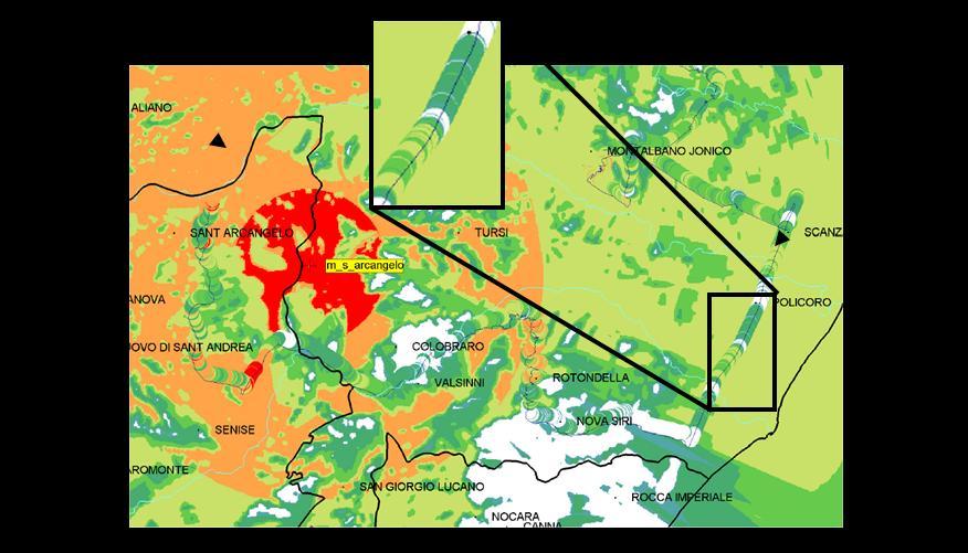
11 Example of Radio Coverage Study Coverage prediction Measurements 11

12 Simulcast Key Factors Issue: to manage radio communications in overlapping areas Solution: implementation of effective procedures for synchronisation, equalisation and voting Result: the radio network acts as a single virtual repeater synchronisation equalisation voting Virtual repeater MAIN BENEFITS: The coverage area is actually improved, compared to the repeaters single contributions. Only one frequency pair RF spectral efficiency cost savings for licensed frequencies Optimal coverage of wide areas Easy-to-use Same operations like under a single site repeater 12
13 DMR Simulcast Delay Spread - 1 Two signals transmitted at precisely the same time will arrive at a receiver at different times, depending on the distance that the signal travels. This difference in arrival times of the two signals time is known as delay. The combined effect of multiple signals in a simulcast environment can be computed using the "Delay Spread" factor. A method of quantifying modulation performance in simulcast and multipath environments is desired. Hess designed a model, called the multipath spread model. The model is based on the observation that for signal delays that are small with respect to the symbol time, the bit error rate (BER) observed is a function of RMS value of the time delays d i of the various signals weighted by their respective power levels P i. This delay spread represents the entire range of multipath possibilities to a single number. The multipath spread for N signals is given by: Since BER is affected by Tm more strongly than N, any value of N can be more simply represented as if it were due to two rays of equal signal strength. This would be interpreted as Tm can be calculated by evaluating for two signals, where P1 equals P2. The value for Tm is the absolute time difference in the arrival of the two signals. 13
14 DMR Simulcast Delay Spread - 2 In the simulcast delay spread Hess studies, two parameters are used: the Capture Margin and the Maximum Simulcast Delay Spread value: "Capture Margin": if any signal exceeds at least one from all the others by this value, then this single signal is the only one recognized by the receiver. If the capture margin criterion is not met, the delay spread value is computed with the multipath spread delay model "Maximum Simulcast Delay Spread (SDS)": it is the maximum permitted delay value. If the computed delay spread exceeds the maximum value, then the point is considered to have no usable signal. If the computed delay is less than the maximum specified delay, the signal at the point is the sum of the received power of the signals The delay spread capabilities of the various modulations are predominantly a function of the characteristics of that modulation. Given the delay spread capabilities of the various modulations, it is possible to predict system performance for the applicable modulation type and thereby design the system to meet coverage and propagation requirements. 14
, non-capture (or overlap) areas: where the signal strength from adjacent transmitters is approximately equal In non-capture (or overlap)")
15 DMR Simulcast Delay Spread - 3 Slave Master Slave Slave The whole simulcast-coverage area can be separated into two main types: capture areas: radio terminals receive a signal from only one transmitter (or where one signal only captures the receiver), non-capture (or overlap) areas: where the signal strength from adjacent transmitters is approximately equal In non-capture (or overlap) areas the delay made by the multipath from the two or more RBS toward the radio terminal must be simulated, controlled and adjusted to be non-destructive. 15
 vs Multi-Path Spread (μs) The delay spread curves can be represented for various DAQ values, as the value of Tm is associated to the BER% and to the DAQ.")

16 DMR Simulcast Delay Spread - 4 Hess described a method where multipath spread and the total signal power necessary for given BER criteria are plotted and used to determine coverage. BER (%) vs Multi-Path Spread (μs) The delay spread curves can be represented for various DAQ values, as the value of Tm is associated to the BER% and to the DAQ. TIA reported DAQ Scores DMR 2 slot TDMA (AMBE +2) Simulcast Performance Cf/N vs Multi-Path Spread (μs) BER (%) The loss of sensitivity becomes extreme as the delay spread increases. An important reference is the asymptote on the delay spread axis, which is the point at which it becomes impossible to meet the BER criterion independently of the signal strength. Another important reference for a modulation is the signal strength necessary for a given BER at Tm = 0 μs. Given these attributes, the delay performance of the candidate modulation is bounded. 16


17 DMR Simulcast Delay Spread - 5 Local reflectors Master Base Station Local reflectors Mobile d1 Slave Base Station d2 The delay spread can be expressed in a simplified way as: 17
18 DMR Simulcast Delay Spread in practice - 1 If the differences in travel times of the various paths are negligible compared to the symbol time, the signal components arrive at the receiver at the same time, leading to an increase in the intensity of the signal received by the sum of the components. The higher the bit rate of the system, the lower the symbol time => the differences in arrival times can become significant compared to the symbol time itself. This effect creates destructive Inter Symbol Interference (ISI) due to the sum of the current symbol with echoes of previous symbols, with an adverse effect on system performance. The ISI begins to degrade the BER when the delay spread is greater than 1/7 to 1/10 of symbol time. DMR modulation has a symbol duration of µs, so attention has to be payed when the delay spread is higher than 20 to 30 µs. 18
19 DMR Simulcast Delay Spread in practice - 2 To reduce the interference in the overlapping areas it is necessary to maintain the RMS delay spread at a value of less than 20 to 30 µsec. To achieve this goal there are typically three means: by introducing a delay or an advance on the transmitted signal from RBS, this is achieved by changing Overlap Area Distance Compensation (OADC) parameters; by changing the antenna bearing and kind (omnidirectional vs directional antenna); by changing the RF power level of the RBS (also with potential energy savings). The delay spread has higher impact in outdoor environments because multiple paths have more impact than in indoor environments. 19
20 DMR Simulcast Delay Spread in practice - 3 Delay spread analysis should be performed within a distance range great enough (ideally infinity) to take into account also the RF field components from those RBS which, while not contributing to the communication (far more than the theoretical 75Km for DMR), can still contribute the delay spread. Once completed, the static and dynamic analysis and solved the delay spread issue, it is necessary to verify that the new coverage allows the communication in all the user s area. This is because the changes due to the solution of the delay spread issue change the RF coverage of the system. If needed, it is necessary to iterate the described procedure starting from the calculation of the link budget and correct the parameters (powers, delays, antenna bearings and types, etc.) so as to ensure RF coverage and solve the delay spread issue in the service area. 20
 delay offset for equalized map The Signal Delay Spread (SDS) capability is the amount of delay between two independently faded equal")

21 DMR Simulcast Delay Spread - simulation examples 1 Performance for DAQ = 3.4 (BER = 2.0%) delay offset for equalized map The Signal Delay Spread (SDS) capability is the amount of delay between two independently faded equal amplitude signals that can be tolerated, when the standard input signal is applied through a faded channel simulator that will result in the standard BER at the receiver detector. The channel simulator provides a composite signal of two, equal amplitude, independently faded rays, the last of which is a delayed version of the first. 21


22 DMR Simulcast Delay Spread - simulation examples 2 22

23 DMR Simulcast Delay Spread - simulation examples 3 23


24 DMR Simulcast Delay Spread - simulation examples 4 24


25 DMR Simulcast Delay Spread - simulation examples 4 25

26 Thank you! For more info: 26

27 I M P R E S S U M PMRExpo bis 29. November 2018 in Köln Veranstalter und Herausgeber EW Medien und Kongresse GmbH Reinhardtstr Berlin November 2018 Copyright: Das Werk einschließlich aller seiner Teile ist urheberrechtlich geschützt. Jede Verwertung außerhalb der engen Grenzen des Urheberrechtsgesetzes ist ohne Zustimmung des Verlages unzulässig und strafbar. Das gilt vor allem für Vervielfältigungen in irgendeiner Form (Fotokopie, Mikrokopie oder ein anderes Verfahren), Übersetzung und die Einspeicherung und Verarbeitung in elektronischen Systemen.
How to Build a DMR Simulcast Network
 How to Build a DMR Simulcast Network Workshop: Digital Mobile Radio Association DMR Alessandro Guido DMR System Design, Leonardo S.p.A. Augusto Colombo DMR Sales Technical Support, Leonardo S.p.A. 1 Broadcast:
European PMR Communication Session What s happening in UK?
 European PMR Communication Session What s happening in UK? Peter Clemons Founder & Managing Director, Quixoticity Kolnemesse, Kӧln November 24, 2015 11/24/2015 1 Quixoticity? Clemons Consulting dedicated
Coverage Impact of Implementing Narrowband Equipment. Bernie Olson Chair TIA TR8.18
 Coverage Impact of Implementing Narrowband Equipment Bernie Olson Chair TIA TR8.18 It Depends ON Lots of variables to take into consideration Migration process Link Budget Tradeoff of sensitivity and interference
PMR in France Shift towards LTE
 PMR in France Shift towards LTE PMRexpo 2015 Cologne, the 24th of November 2015 Agenda PMR market Overview Shifting towards LTE Zoom on indoor PMR market Overview Shifting towards LTE Zoom on indoor The
Simulcasting Project 25
 ATLAS Simulcasting Project 25 2013 April Copyright 2012-2013 by EFJohnson Technologies, Inc. The EFJohnson Technologies logo, ATLAS, and StarGate are trademarks of EFJohnson Technologies, Inc. All other
Revision of Lecture One
 Revision of Lecture One System blocks and basic concepts Multiple access, MIMO, space-time Transceiver Wireless Channel Signal/System: Bandpass (Passband) Baseband Baseband complex envelope Linear system:
Linking Narrowband to Broadband Networks (TETRA -Mission Critical LTE Interworking) PMRexpo Workshop, 28 Nov 2017, Cologne, Germany
 PMRexpo Workshop, 28 Nov 2017, Cologne, Germany") Linking Narrowband to Broadband Networks (TETRA -Mission Critical LTE Interworking) PMRexpo Workshop, 28 Nov 2017, Cologne, Germany What are the important aspects for an operator? Topics What is the status
Linking Narrowband to Broadband Networks (TETRA -Mission Critical LTE Interworking) PMRexpo Workshop, 28 Nov 2017, Cologne, Germany What are the important aspects for an operator? Topics What is the status
ECE 476/ECE 501C/CS Wireless Communication Systems Winter Lecture 6: Fading
 ECE 476/ECE 501C/CS 513 - Wireless Communication Systems Winter 2003 Lecture 6: Fading Last lecture: Large scale propagation properties of wireless systems - slowly varying properties that depend primarily
ECE 476/ECE 501C/CS Wireless Communication Systems Winter Lecture 6: Fading
 ECE 476/ECE 501C/CS 513 - Wireless Communication Systems Winter 2004 Lecture 6: Fading Last lecture: Large scale propagation properties of wireless systems - slowly varying properties that depend primarily
ECE 476/ECE 501C/CS Wireless Communication Systems Winter Lecture 6: Fading
 ECE 476/ECE 501C/CS 513 - Wireless Communication Systems Winter 2005 Lecture 6: Fading Last lecture: Large scale propagation properties of wireless systems - slowly varying properties that depend primarily
Revision of Lecture One
 Revision of Lecture One System block Transceiver Wireless Channel Signal / System: Bandpass (Passband) Baseband Baseband complex envelope Linear system: complex (baseband) channel impulse response Channel:
PROPAGATION MODELING 4C4
 PROPAGATION MODELING ledoyle@tcd.ie 4C4 http://ledoyle.wordpress.com/temp/ Classification Band Initials Frequency Range Characteristics Extremely low ELF < 300 Hz Infra low ILF 300 Hz - 3 khz Ground wave
Information on the Evaluation of VHF and UHF Terrestrial Cross-Border Frequency Coordination Requests
 Issue 1 May 2013 Spectrum Management and Telecommunications Technical Bulletin Information on the Evaluation of VHF and UHF Terrestrial Cross-Border Frequency Coordination Requests Aussi disponible en
Propagation Modelling White Paper
 Propagation Modelling White Paper Propagation Modelling White Paper Abstract: One of the key determinants of a radio link s received signal strength, whether wanted or interfering, is how the radio waves
Atoll. SPM Calibration Guide. RF Planning and Optimisation Software. Version AT271_MCG_E2
 Atoll RF Planning and Optimisation Software Version 2.7.1 SPM Calibration Guide AT271_MCG_E2 Contact Information Forsk (Head Office) 7 rue des Briquetiers 31700 Blagnac France www.forsk.com sales@forsk.com
Specifying, predicting and testing:
 Specifying, predicting and testing: Three steps to coverage confidence on your digital radio network EXECUTIVE SUMMARY One of the most important properties of a radio network is coverage. Yet because radio
Atoll SPM (Standard Propagation Model) calibration guide
 calibration guide") Atoll SPM (Standard Propagation Model) calibration guide January 2004 FORSK 7 rue des Briquetiers 31700 BLAGNAC France www.forsk.com SARL au capital de 150 000 - RCS Toulouse 87 B 1302 - SIRET 342 662
Atoll SPM (Standard Propagation Model) calibration guide January 2004 FORSK 7 rue des Briquetiers 31700 BLAGNAC France www.forsk.com SARL au capital de 150 000 - RCS Toulouse 87 B 1302 - SIRET 342 662
Evaluation of Power Budget and Cell Coverage Range in Cellular GSM System
 Evaluation of Power Budget and Cell Coverage Range in Cellular GSM System Dr. S. A. Mawjoud samialmawjoud_2005@yahoo.com Abstract The paper deals with study of affecting parameters on the communication
The Radio Channel. COS 463: Wireless Networks Lecture 14 Kyle Jamieson. [Parts adapted from I. Darwazeh, A. Goldsmith, T. Rappaport, P.
 The Radio Channel COS 463: Wireless Networks Lecture 14 Kyle Jamieson [Parts adapted from I. Darwazeh, A. Goldsmith, T. Rappaport, P. Steenkiste] Motivation The radio channel is what limits most radio
Small-Scale Fading I PROF. MICHAEL TSAI 2011/10/27
 Small-Scale Fading I PROF. MICHAEL TSAI 011/10/7 Multipath Propagation RX just sums up all Multi Path Component (MPC). Multipath Channel Impulse Response An example of the time-varying discrete-time impulse
Simulation of Outdoor Radio Channel
 Simulation of Outdoor Radio Channel Peter Brída, Ján Dúha Department of Telecommunication, University of Žilina Univerzitná 815/1, 010 6 Žilina Email: brida@fel.utc.sk, duha@fel.utc.sk Abstract Wireless
Antennas & Propagation. CSG 250 Fall 2007 Rajmohan Rajaraman
 Antennas & Propagation CSG 250 Fall 2007 Rajmohan Rajaraman Introduction An antenna is an electrical conductor or system of conductors o Transmission - radiates electromagnetic energy into space o Reception
iq.link Key Features Comsearch A CommScope Company
 2016 iq.link Key Features Comsearch A CommScope Company Table of Contents Near and Non-Line of Sight (nlos) Propagation Model:... 2 Radio State Analysis Graphics... 3 Comprehensive support for Adaptive
Roger Kane Managing Director, Vicom Australia
 Understanding and testing of DMR standard Roger Kane Managing Director, Vicom Australia @CommsConnectAus#comms2014 Presentation Title: Understanding and Testing DMR Speaker: Roger Kane @CommsConnectAus
Simulcast Radio Network Design. Jay M. Jacobsmeyer, P.E. Pericle Communications Co Vindicator Drive, Suite 100 Colorado Springs, CO 80919
 Simulcast Radio Network Design Jay M. Jacobsmeyer, P.E. Pericle Communications Co. 1910 Vindicator Drive, Suite 100 Colorado Springs, CO 80919 Outline Company Overview Background Information Needs Analysis
RECOMMENDATION ITU-R SF.1719
 Rec. ITU-R SF.1719 1 RECOMMENDATION ITU-R SF.1719 Sharing between point-to-point and point-to-multipoint fixed service and transmitting earth stations of GSO and non-gso FSS systems in the 27.5-29.5 GHz
Optimizing 16 db Capture Effect to Overcome Class A 'Channelized' Signal Booster Group Delay problems within Public Safety Communications Systems
 Optimizing 16 db Capture Effect to Overcome Class A 'Channelized' Signal Booster Group Delay problems within Public Safety Communications Systems July 30, 2008 2008 Jack Daniel Company 2008 Jack Daniel
Supporting Network Planning Tools II
 Session 5.8 Supporting Network Planning Tools II Roland Götz LS telcom AG / Spectrocan 1 Modern Radio Network Planning Tools Radio Network Planning Tool Data / Result Output Data Management Network Processor
Mobile Radio Wave propagation channel- Path loss Models
 Mobile Radio Wave propagation channel- Path loss Models 3.1 Introduction The wireless Communication is one of the integral parts of society which has been a focal point for sharing information with different
UNIK4230: Mobile Communications Spring 2013
 UNIK4230: Mobile Communications Spring 2013 Abul Kaosher abul.kaosher@nsn.com Mobile: 99 27 10 19 1 UNIK4230: Mobile Communications Propagation characteristis of wireless channel Date: 07.02.2013 2 UNIK4230:
1/27. White Paper June Signal propagation modeling In Urban Environment. Emmanuel Grenier
 1/27 White Paper June 2005 Signal propagation modeling In Urban Environment Emmanuel Grenier 2/27 Signal propagation modeling in Urban Environment When working with ICS Telecom to simulate wireless propagation
ADJACENT BAND COMPATIBILITY OF 400 MHZ TETRA AND ANALOGUE FM PMR AN ANALYSIS COMPLETED USING A MONTE CARLO BASED SIMULATION TOOL
 European Radiocommunications Committee (ERC) within the European Conference of Postal and Telecommunications Administrations (CEPT) ADJACENT BAND COMPATIBILITY OF 400 MHZ AND ANALOGUE FM PMR AN ANALYSIS
Level 6 Graduate Diploma in Engineering Wireless and mobile communications
 9210-119 Level 6 Graduate Diploma in Engineering Wireless and mobile communications Sample Paper You should have the following for this examination one answer book non-programmable calculator pen, pencil,
King Fahd University of Petroleum & Minerals Computer Engineering Dept
 King Fahd University of Petroleum & Minerals Computer Engineering Dept COE 543 Mobile and Wireless Networks Term 0 Dr. Ashraf S. Hasan Mahmoud Rm -148-3 Ext. 174 Email: ashraf@ccse.kfupm.edu.sa 4//003
3GPP TR V7.0.0 ( )
") TR 25.816 V7.0.0 (2005-12) Technical Report 3rd Generation Partnership Project; Technical Specification Group Radio Access Network; UMTS 900 MHz Work Item Technical Report (Release 7) The present document
TR 25.816 V7.0.0 (2005-12) Technical Report 3rd Generation Partnership Project; Technical Specification Group Radio Access Network; UMTS 900 MHz Work Item Technical Report (Release 7) The present document
Path-loss and Shadowing (Large-scale Fading) PROF. MICHAEL TSAI 2015/03/27
 PROF. MICHAEL TSAI 2015/03/27") Path-loss and Shadowing (Large-scale Fading) PROF. MICHAEL TSAI 2015/03/27 Multipath 2 3 4 5 Friis Formula TX Antenna RX Antenna = 4 EIRP= Power spatial density 1 4 6 Antenna Aperture = 4 Antenna Aperture=Effective
Path-loss and Shadowing (Large-scale Fading) PROF. MICHAEL TSAI 2015/03/27 Multipath 2 3 4 5 Friis Formula TX Antenna RX Antenna = 4 EIRP= Power spatial density 1 4 6 Antenna Aperture = 4 Antenna Aperture=Effective
Introduction. TV Coverage and Interference, February 06, 2004.
 A New Prediction Model for M/H Mobile DTV Service Prepared for OMVC June 28, 2011 Charles Cooper, du Treil, Lundin & Rackley, Inc. Victor Tawil, National Association of Broadcasters Introduction The Open
RECOMMENDATION ITU-R F.1819
 Rec. ITU-R F.1819 1 RECOMMENDATION ITU-R F.1819 Protection of the radio astronomy service in the 48.94-49.04 GHz band from unwanted emissions from HAPS in the 47.2-47.5 GHz and 47.9-48.2 GHz bands * (2007)
Technical Support to Defence Spectrum LTE into Wi-Fi Additional Analysis. Definitive v1.0-12/02/2014. Ref: UK/2011/EC231986/AH17/4724/V1.
 Technical Support to Defence Spectrum LTE into Wi-Fi Additional Analysis Definitive v1.0-12/02/2014 Ref: UK/2011/EC231986/AH17/4724/ 2014 CGI IT UK Ltd 12/02/2014 Document Property Value Version v1.0 Maturity
RECOMMENDATION ITU-R BS
 Rec. ITU-R BS.1194-1 1 RECOMMENDATION ITU-R BS.1194-1 SYSTEM FOR MULTIPLEXING FREQUENCY MODULATION (FM) SOUND BROADCASTS WITH A SUB-CARRIER DATA CHANNEL HAVING A RELATIVELY LARGE TRANSMISSION CAPACITY
CHAPTER 2 WIRELESS CHANNEL
 CHAPTER 2 WIRELESS CHANNEL 2.1 INTRODUCTION In mobile radio channel there is certain fundamental limitation on the performance of wireless communication system. There are many obstructions between transmitter
EC 551 Telecommunication System Engineering. Mohamed Khedr
 EC 551 Telecommunication System Engineering Mohamed Khedr http://webmail.aast.edu/~khedr 1 Mohamed Khedr., 2008 Syllabus Tentatively Week 1 Week 2 Week 3 Week 4 Week 5 Week 6 Week 7 Week 8 Week 9 Week
International Journal of Engineering and Technology Volume 3 No. 6, June, 2013
 International Journal of Engineering and Technology Volume 3 No. 6, June, 2013 Spectrum Compatibility Study of Terrestrial Digital Audio Broadcasting System and the Microwave Radio Relay Links in the L-Band
NXDN Signal and Interference Contour Requirements An Empirical Study
 NXDN Signal and Interference Contour Requirements An Empirical Study Icom America Engineering December 2007 Contents Introduction Results Analysis Appendix A. Test Equipment Appendix B. Test Methodology
Multi-Path Fading Channel
 Instructor: Prof. Dr. Noor M. Khan Department of Electronic Engineering, Muhammad Ali Jinnah University, Islamabad Campus, Islamabad, PAKISTAN Ph: +9 (51) 111-878787, Ext. 19 (Office), 186 (Lab) Fax: +9
Review of Path Loss models in different environments
 Review of Path Loss models in different environments Mandeep Kaur 1, Deepak Sharma 2 1 Computer Scinece, Kurukshetra Institute of Technology and Management, Kurukshetra 2 H.O.D. of CSE Deptt. Abstract
Channel Models. Spring 2017 ELE 492 FUNDAMENTALS OF WIRELESS COMMUNICATIONS 1
 Channel Models Spring 2017 ELE 492 FUNDAMENTALS OF WIRELESS COMMUNICATIONS 1 Narrowband Channel Models Statistical Approach: Impulse response modeling: A narrowband channel can be represented by an impulse
WHITEPAPER IMPRovIng THE safety And EFFEcTIvEnEss of TETRA RAdIo users THRougH IncREAsEd RAdIo sensitivity And PoWER
 MAY 2012 IMPROVING THE SAFETY AND EFFECTIVENESS OF TETRA RADIO USERS THROUGH INCREASED RADIO SENSITIVITY AND POWER 2dB or not 2dB, that is the question * *Hamlet s guide to radio planning Introduction
Channel Modelling ETIM10. Propagation mechanisms
 Channel Modelling ETIM10 Lecture no: 2 Propagation mechanisms Ghassan Dahman \ Fredrik Tufvesson Department of Electrical and Information Technology Lund University, Sweden 2012-01-20 Fredrik Tufvesson
DMR Rx Test Solution. Signal Analyzer MS2830A. Reference Specifications
 Product Introduction DMR Rx Test Solution Signal Analyzer MS2830A Reference Specifications ETSI EN 300 113 Version 2.1.1 (2016-08) / Technical characteristics of the receiver ETSI TS 102 361-1 Version
Application Note 37. Emulating RF Channel Characteristics
 Application Note 37 Emulating RF Channel Characteristics Wireless communication is one of the most demanding applications for the telecommunications equipment designer. Typical signals at the receiver
Link Budget Calculation
 Link Budget Calculation Training materials for wireless trainers This 60 minute talk is about estimating wireless link performance by using link budget calculations. It also introduces the Radio Mobile
UWB Channel Modeling
 Channel Modeling ETIN10 Lecture no: 9 UWB Channel Modeling Fredrik Tufvesson & Johan Kåredal, Department of Electrical and Information Technology fredrik.tufvesson@eit.lth.se 2011-02-21 Fredrik Tufvesson
Chapter 1: Telecommunication Fundamentals
 Chapter 1: Telecommunication Fundamentals Block Diagram of a communication system Noise n(t) m(t) Information (base-band signal) Signal Processing Carrier Circuits s(t) Transmission Medium r(t) Signal
Digital Audio Broadcasting Eureka-147. Minimum Requirements for Terrestrial DAB Transmitters
 Digital Audio Broadcasting Eureka-147 Minimum Requirements for Terrestrial DAB Transmitters Prepared by WorldDAB September 2001 - 2 - TABLE OF CONTENTS 1 Scope...3 2 Minimum Functionality...3 2.1 Digital
How to Conduct a Drive Test Survey
 How to Conduct a Drive Test Survey Presented By: Jay M. Jacobsmeyer, P.E. George W. Weimer, P.E. Pericle Communications Company Trott Communications Group 1910 Vindicator Drive, Suite 100 4320 N. Beltline
Channel Modeling ETI 085
 Channel Modeling ETI 085 Overview Lecture no: 9 What is Ultra-Wideband (UWB)? Why do we need UWB channel models? UWB Channel Modeling UWB channel modeling Standardized UWB channel models Fredrik Tufvesson
Single Frequency Network Structural Aspects & Practical Field Considerations
 Single Frequency Structural Aspects & Practical Field Considerations November 2011 Featuring GatesAir s Rich Redmond Chief Product Officer Copyright 2015 GatesAir, Inc. All rights reserved. Single frequency
1 Minimum usable field strength
 1 RECOMMENDATION ITU-R BS.412-8* PLANNING STANDARDS FOR FM SOUND BROADCASTING AT VHF (Questions ITU-R 74/1 and ITU-R 11/1) (1956-1959-1963-1974-1978-1982-1986-199-1994-1995-1998) The ITU Radiocommunication
S Postgraduate Course in Radiocommunications. WCDMA Radio Link Performance Indicators. Seminar Mervi Berner
 S-72.333 Postgraduate Course in Radiocommunications Seminar 21.01.2003 Mervi Berner Content Definitions of WCDMA Radio Link Performance Indicators Multipath Channel Conditions and Services Link-level Simulation
Point to point Radiocommunication
 Point to point Radiocommunication SMS4DC training seminar 7 November 1 December 006 1 Technical overview Content SMS4DC Software link calculation Exercise 1 Point-to-point Radiocommunication Link A Radio
Radio Propagation Fundamentals
 Radio Propagation Fundamentals Concept of Electromagnetic Wave Propagation Mechanisms Modes of Propagation Propagation Models Path Profiles Link Budget Fading Channels Electromagnetic (EM) Waves EM Wave
Adjacent Channel Studies in the FM Band
 Adjacent Channel Studies in the FM Band Prepared for the NRSC By ibiquity Digital Corporation 11/09/00 Adjacent Channel Studies in the FM Band Page 1 As part of its AM IBOC development effort, ibiquity
LECTURE 3. Radio Propagation
 LECTURE 3 Radio Propagation 2 Simplified model of a digital communication system Source Source Encoder Channel Encoder Modulator Radio Channel Destination Source Decoder Channel Decoder Demod -ulator Components
Project = An Adventure : Wireless Networks. Lecture 4: More Physical Layer. What is an Antenna? Outline. Page 1
 Project = An Adventure 18-759: Wireless Networks Checkpoint 2 Checkpoint 1 Lecture 4: More Physical Layer You are here Done! Peter Steenkiste Departments of Computer Science and Electrical and Computer
EITN85, FREDRIK TUFVESSON, JOHAN KÅREDAL ELECTRICAL AND INFORMATION TECHNOLOGY. Why do we need UWB channel models?
 Wireless Communication Channels Lecture 9:UWB Channel Modeling EITN85, FREDRIK TUFVESSON, JOHAN KÅREDAL ELECTRICAL AND INFORMATION TECHNOLOGY Overview What is Ultra-Wideband (UWB)? Why do we need UWB channel
Channel. Muhammad Ali Jinnah University, Islamabad Campus, Pakistan. Multi-Path Fading. Dr. Noor M Khan EE, MAJU
 Instructor: Prof. Dr. Noor M. Khan Department of Electronic Engineering, Muhammad Ali Jinnah University, Islamabad Campus, Islamabad, PAKISTAN Ph: +9 (51) 111-878787, Ext. 19 (Office), 186 (Lab) Fax: +9
Radio propagation modeling on 433 MHz
 Ákos Milánkovich 1, Károly Lendvai 1, Sándor Imre 1, Sándor Szabó 1 1 Budapest University of Technology and Economics, Műegyetem rkp. 3-9. 1111 Budapest, Hungary {milankovich, lendvai, szabos, imre}@hit.bme.hu
Integrated Mission-Critical Network Planning Using EDX SignalPro
 Integrated Mission-Critical Network Planning Using EDX SignalPro Integrated Mission-Critical Network Planning Using SignalPro Steve Webster Director of Sales Engineering EDX Wireless, Inc. (www.edx.com)
Wireless Signal Propagation Concepts
 Wireless Signal Propagation Concepts NARUC 2017 Presented as part of: Mobile Broadband, Wireless Propagation, and the 706 NOI Presented by Adam Nelson Senior Consultant Federal Engineering, Inc. November
Measuring ACPR of W-CDMA signals with a spectrum analyzer
 Measuring ACPR of W-CDMA signals with a spectrum analyzer When measuring power in the adjacent channels of a W-CDMA signal, requirements for the dynamic range of a spectrum analyzer are very challenging.
Session2 Antennas and Propagation
 Wireless Communication Presented by Dr. Mahmoud Daneshvar Session2 Antennas and Propagation 1. Introduction Types of Anttenas Free space Propagation 2. Propagation modes 3. Transmission Problems 4. Fading
Contents. Telecom Service Chae Y. Lee. Data Signal Transmission Transmission Impairments Channel Capacity
 Data Transmission Contents Data Signal Transmission Transmission Impairments Channel Capacity 2 Data/Signal/Transmission Data: entities that convey meaning or information Signal: electric or electromagnetic
COMPATIBILITY AND SHARING ANALYSIS BETWEEN DVB T AND TALKBACK LINKS IN BANDS IV AND V
 European Radiocommunications Committee (ERC) within the European Conference of Postal and Telecommunications Administrations (CEPT) COMPATIBILITY AND SHARING ANALYSIS BETWEEN DVB T AND TALKBACK LINKS IN
Antennas and Propagation. Chapter 5
 Antennas and Propagation Chapter 5 Introduction An antenna is an electrical conductor or system of conductors Transmission - radiates electromagnetic energy into space Reception - collects electromagnetic
Protection Ratio Calculation Methods for Fixed Radiocommunications Links
 Protection Ratio Calculation Methods for Fixed Radiocommunications Links C.D.Squires, E. S. Lensson, A. J. Kerans Spectrum Engineering Australian Communications and Media Authority Canberra, Australia
ECC Report 276. Thresholds for the coordination of CDMA and LTE broadband systems in the 400 MHz band
 ECC Report 276 Thresholds for the coordination of CDMA and LTE broadband systems in the 400 MHz band 27 April 2018 ECC REPORT 276 - Page 2 0 EXECUTIVE SUMMARY This Report provides technical background
FM Transmission Systems Course
 FM Transmission Systems Course Course Description An FM transmission system, at its most basic level, consists of the transmitter, the transmission line and antenna. There are many variables within these
Wireless Physical Layer Concepts: Part III
 Wireless Physical Layer Concepts: Part III Raj Jain Professor of CSE Washington University in Saint Louis Saint Louis, MO 63130 Jain@cse.wustl.edu These slides are available on-line at: http://www.cse.wustl.edu/~jain/cse574-08/
Technical Annex. This criterion corresponds to the aggregate interference from a co-primary allocation for month.
 RKF Engineering Solutions, LLC 1229 19 th St. NW, Washington, DC 20036 Phone 202.463.1567 Fax 202.463.0344 www.rkf-eng.com 1. Protection of In-band FSS Earth Stations Technical Annex 1.1 In-band Interference
(Refer Slide Time: 00:01:31 min)
") Wireless Communications Dr. Ranjan Bose Department of Electrical Engineering Indian Institute of Technology, Delhi Lecture No. # 12 Mobile Radio Propagation (Continued) We will start today s lecture with
Wireless Communications Dr. Ranjan Bose Department of Electrical Engineering Indian Institute of Technology, Delhi Lecture No. # 12 Mobile Radio Propagation (Continued) We will start today s lecture with
Narrow- and wideband channels
 RADIO SYSTEMS ETIN15 Lecture no: 3 Narrow- and wideband channels Ove Edfors, Department of Electrical and Information technology Ove.Edfors@eit.lth.se 27 March 2017 1 Contents Short review NARROW-BAND
NATIONAL INSTITUTE OF TECHNOLOGY, Arunachal Pradesh
 NATIONAL INSTITUTE OF TECHNOLOGY, Arunachal Pradesh (Established by Ministry of Human Resources Development, Govt. Of India) Yupia, District-Papum Pare, Arunachal Pradesh -791112. M.Techl20I End-semester
Point-to-Multipoint Coexistence with C-band FSS. March 27th, 2018
 Point-to-Multipoint Coexistence with C-band FSS March 27th, 2018 1 Conclusions 3700-4200 MHz point-to-multipoint (P2MP) systems could immediately provide gigabit-class broadband service to tens of millions
Wireless Physical Layer Concepts: Part II
 Wireless Physical Layer Concepts: Part II Raj Jain Professor of CSE Washington University in Saint Louis Saint Louis, MO 63130 Jain@cse.wustl.edu Audio/Video recordings of this lecture are available at:
TESTING OF FIXED BROADBAND WIRELESS SYSTEMS AT 5.8 GHZ
 To be presented at IEEE Denver / Region 5 Conference, April 7-8, CU Boulder, CO. TESTING OF FIXED BROADBAND WIRELESS SYSTEMS AT 5.8 GHZ Thomas Schwengler Qwest Communications Denver, CO (thomas.schwengler@qwest.com)
Abstract. Propagation tests for land-mobile radio service
 Abstract Propagation tests for land-mobile radio service VHF (200MHz) and UHF (453, 922, 1310, 1430, 1920MHz) Various situations of irregular terrain/environmental clutter The results analyzed statistically
Lecture 1 Wireless Channel Models
 MIMO Communication Systems Lecture 1 Wireless Channel Models Prof. Chun-Hung Liu Dept. of Electrical and Computer Engineering National Chiao Tung University Spring 2017 2017/3/2 Lecture 1: Wireless Channel
Radio Path Prediction Software
 Radio Path Prediction Software for Command and Control Scenario Developers Reference# C-168, Michael Shattuck Command and Control Research and Technology Symposium June 2006 Topics Link Planning for Wireless
Reflection. Diffraction. Transmission. Scattering
 WIRELESS TRANSMISSION 649 Reflection Diffraction Transmission Scattering Figure 13.5 Mechanisms of radio propagation. elements follows some geometric pattern (example, linearly spaced elements, elements
Cellular Expert Radio Links module features
 Cellular Expert Radio Links module features Tasks Features Network data management Site, sector, construction, customer, repeater management: Add Edit Move Copy Delete Site re-use patterns for nominal
David Tipper. Graduate Telecommunications and Networking Program
 Wireless Communication Fundamentals David Tipper Associate Professor Graduate Telecommunications and Networking Program University it of Pittsburgh Telcom 2700 Slides 2 Wireless Networks Wireless Wide
Wireless Channel Propagation Model Small-scale Fading
 Wireless Channel Propagation Model Small-scale Fading Basic Questions T x What will happen if the transmitter - changes transmit power? - changes frequency? - operates at higher speed? Transmit power,
Mitigating Interference & Maximizing Throughput in 700MHz for SCADA
 Mitigating Interference & Maximizing Throughput in 700MHz for SCADA Paul Reid and Kathy Shaft (GRE) October 2018 WAS SPUN OUT OF 2 3 Phoenix US Headquarters US Headquarters Technical Support Hub Repair
Antennas and Propagation
 Antennas and Propagation Chapter 5 Introduction An antenna is an electrical conductor or system of conductors Transmission - radiates electromagnetic energy into space Reception - collects electromagnetic
5 GHz Radio Channel Modeling for WLANs
 5 GHz Radio Channel Modeling for WLANs S-72.333 Postgraduate Course in Radio Communications Jarkko Unkeri jarkko.unkeri@hut.fi 54029P 1 Outline Introduction IEEE 802.11a OFDM PHY Large-scale propagation
Input to FM54 on OOB emissions due to UMTS or LTE signals
 REFERENCE O-8751-1.0 FREQUENCY MANAGEMENT WORKING GROUP Input to FM54 on OOB emissions due to UMTS or LTE signals NAME DATE VISA Author FM Drafting Group 10/2014 D. Martens Reviewed Endorsed FM WORKING
Chapter 2 Channel Equalization
 Chapter 2 Channel Equalization 2.1 Introduction In wireless communication systems signal experiences distortion due to fading [17]. As signal propagates, it follows multiple paths between transmitter and
New spectrum for audio PMSE. Further details on approach to modelling and sharing in the band MHz
 New spectrum for audio PMSE Further details on approach to modelling and sharing in the band 960-1164 MHz Consultation update Publication date: 08 January 2016 About this document In response to our consultation
03_57_104_final.fm Page 97 Tuesday, December 4, :17 PM. Problems Problems
 03_57_104_final.fm Page 97 Tuesday, December 4, 2001 2:17 PM Problems 97 3.9 Problems 3.1 Prove that for a hexagonal geometry, the co-channel reuse ratio is given by Q = 3N, where N = i 2 + ij + j 2. Hint: