Channel Modelling ETIM10. Propagation mechanisms
|
|
|
- Arnold Carr
- 5 years ago
- Views:
Transcription
1 Channel Modelling ETIM10 Lecture no: 2 Propagation mechanisms Ghassan Dahman \ Fredrik Tufvesson Department of Electrical and Information Technology Lund University, Sweden Fredrik Tufvesson - ETIM10 1
2 Contents Free space loss Propagation mechanisms Reflection Transmission Diffraction Scattering Waveguiding Examples from propagation scenarios Fredrik Tufvesson - ETIM10 2
: L free d 4d 2 2012-01-20 Fredrik Tufvesson -")
3 Free-space loss If we assume RX antenna to be isotropic: P RX 4 d 2 P TX d A RX Attenuation between two isotropic antennas in free space is (free-space loss): L free d 4d Fredrik Tufvesson - ETIM10 3
4 Free-space loss Friis law Received power, with antenna gains G TX and G RX : GRXGTX P d P P G G L d 4d RX TX TX RX TX free 2 P d P G L d G RX db TX db TX db free db RX db 4d P G 10log G TX db TX db 10 RX db In free space, the received power decays with distance at a rate = 20 db/decade 2 Valid in the far field only Fredrik Tufvesson - ETIM10 4
5 Free-space loss What is far field? The free-space loss calculations are only valid in the far field of the antennas. Far-field conditions are assumed far beyond the Rayleigh distance (also known as Fraunhofer distance): d R 2 2 a L where L a is the largest dimesion of the antenna. Another rule of thumb is: At least 10 wavelengths / 2-dipole / Parabolic 2 2r L a d R / 2 / 2 L a 2r 2 8r d R Fredrik Tufvesson - ETIM10 5
6 Example Cellular phone, height 10 cm, f c =900 MHz Rayleigh distance d R =2*0.1 2 /0.333=6 cm For this device the limit is the 10-lambda rule of thumb. Microwave link, antenna diameter 1.2 m, f c =26 GHz Rayleigh distance d R =2*1.2 2 /0.011=250 m For this device the limit is the Rayleigh distance Fredrik Tufvesson - ETIM10 6
7 Fresnel Zones Fresnel zones: successive regions where secondary waves have Tx- Rx path length which are greater than the LOS path length (i.e., phase diff=). The radius of the nth zone: = The propagation follows a space loss as long as the first Fresnel zone is clear Fredrik Tufvesson - ETIM10 7
8 The reference distance d 0 For path-loss propagation models, a close-in distance d 0 is selected such that it lies in the far-field region. = 10 ( ). 20log( ) d For practical systems in the 1-2 GHz region, d 0 is typically chosen to be 1 m in indoor environments, and 100 m or 1 km for outdoor environments. For distances d>d break, the above equation doesn t hold anymore Fredrik Tufvesson - ETIM10 8
9 Propagation mechanisms i r 1 2 t Reflection and transmission Diffraction Scattering Waveguiding Fredrik Tufvesson - ETIM10 9

10 Reflection and transmission (Snell s law) e r conductivity permittivity 1 2 reflected angle sin t sin e 1 2. transmitted angle t Fredrik Tufvesson - ETIM10 10
11 TM and TE waves behave differently Reflection coefficient Transmission coefficient Fredrik Tufvesson - ETIM10 11
12 Ground reflection (2-ray model) For the following scenario the power goes like for distances greater than Fredrik Tufvesson - ETIM10 12
13 The d -4 law = ( ). ( ) if d = ( ). if d > However.. n=4 is not a universal decay exponent Theoretical model is not fulfilled in practice Breakpoint is rarely where theoretically predicted Second breakpoint at the radio horizon (the curvature of the Earth) Fredrik Tufvesson - ETIM10 13
14 Transmission through walls layered structures Total transmission coefficient d T T 1T 2 e j 1R 1 R 2 e 2j total reflection coefficient 1 2 e j e 2j T 1 T 2 with the electrical length in the wall 2 1 d layer cos t Fredrik Tufvesson - ETIM10 14
15 Example: The COST-Hata-Model The COST-Hata-Model is formulated as, For suburban or rural environments: where, L = Median path loss (db) f = Frequency of Transmissionn (MHz) h B = Base station height (m) d = Link distance (km) h R = Mobile station height (m) a(h R ) = Mobile station height correction factor Fredrik Tufvesson - ETIM10 15
16 Diffraction Single or multiple edges makes it possible to go behind corners less pronounced when the wavelength is small compared to objects Fredrik Tufvesson - ETIM10 16
17 Diffraction, Huygen s principle Each point of a wavefront can be considered as a source of a spherical wave Bending around corners and edges Fredrik Tufvesson - ETIM10 17
18 Diffraction coefficient by a screen expjk 0 x The diffraction angle + Total field The Fresnel integral is defined F F F exp j t 2 dt. 2 0 with the Fresnel parameter Fresnel integral ) Fredrik Tufvesson - ETIM10 18
19 Diffraction in real environments For real environments we can represent buildings and objects as multiple screens Fredrik Tufvesson - ETIM10 19
20 Diffraction by multiple screens: Bullington s method tangent Replace all screens with one equivalent screen Height determined by the steepest angle Simple but a bit optimistic equivalent screen E total expjk 0 x 1 2 expj /4 2 F F Fredrik Tufvesson - ETIM10 20
21 Diffraction by multiple screens: Epstein-Petersen Method L 1 L 2 L 3 Compute diffraction loss for each screen separately and add the losses L tot =L 1 +L 2 +L 3 Diffraction The same approach is used also for the ITU model, but with an empirical correction factor Fredrik Tufvesson - ETIM10 21
22 Diffraction by multiple screens: empirical models w The ITU multi-knife-edges model The ITU proposed an extreme simple model for diffraction losses. = + 20 where is the diffraction loss from each separate screen (in db), and is a correcting factor depends Diffraction the distances () among the different screens. The values of :,, are selected from certain assumed distributions that depends on the environment. Q: Use the abovementioned equation to explain the reason behind using the log-normal distribution to model the large-scale fading (shadowing) Fredrik Tufvesson - ETIM10 22
23 Scattering Specular reflection Specular reflection Scattering Smooth surface Rough surface In all cases the law of reflection is obeyed. Flat surfaces that have much larger dimension than are modeled as reflective services. However, the roughness of such surfaces induces non-specular components (scattering) Fredrik Tufvesson - ETIM10 23
24 Scattering by rough surfaces: Kirchhoff theory Requires only the probability density function of the surface amplitude assume no shadowing from surface (no influence among different points) calculate an effective reflection coefficient for the surface for Gaussian surface distribution angle of incidence rough smooth exp 2 k 0 h sin 2 standard deviation of height Fredrik Tufvesson - ETIM10 24
25 Scattering by rough surfaces: Perturbation theory Spatial correlation function h 2 W E r h r h r 2-D location vectors h r h r More accurate than Kirchhoff theory, especially for large angles of incidence and rougher surfaces Generalizes Kirchhoff theory Include shadowing effects by the surface includes spatial correlation of surface how fast are the changes in height calculate an effective reflection coefficient for the surface Fredrik Tufvesson - ETIM10 25
26 Modeling received power due to scattering in the far field (urban mobile systems) For urban mobile systems, the following model is used to compute the received power due to scattering in the far field. = [ ] 30 log where and are the distances from the scattering object to Tx and Rx. RCS (Radar Cross Section) is the surface area of the scattering object. In several European cities, for medium and large buildings located 5 10 km away, RCS values were found to be in the range 14.1dB to 55.7dB Fredrik Tufvesson - ETIM10 26
27 Waveguiding This process models propagation in street canyons, corridors, and tunnels. In wireless channels, this process deviates from the ideal assumptions (e.g., street crossings, rough surfaces, cars, pedestrians, ) Propagation measurements fitted a law, where n varies between 1.5 and Fredrik Tufvesson - ETIM10 27

28 How does the signal reach the receiver Outdoor-to-indoor transmitter receiver Fredrik Tufvesson - ETIM10 28
29 2337 How does the signal reach the receiver In the office Fredrik Tufvesson - ETIM10 29
30 How does the signal leave the transmitter at the roof Fredrik Tufvesson - ETIM10 30


31 In all offices Fredrik Tufvesson - ETIM10 31

32 How does the signal reach the receiver outdoor urban h=23 m h=29 m h=29 m 0 N W E S Cathedr al RX h=30 m Yar d 80 Street 1 TX m 0 h=30 m h=28 m h=28 m BOF h=25 m h=24 m h60 m Transmitter Mottagare Fredrik Tufvesson - ETIM10 32
33 Signal arrives from some specific areas Cathedral Through yard Over BOF Street 1 Street Fredrik Tufvesson - ETIM10 33


34 Diffraction, reflection, scattering, transmission Fredrik Tufvesson - ETIM10 34
35 Outdoor 300 MHz peer-to-peer scenario Center frequency: 285 MHz, 20MHz bandwidth Peer-to-peer measurement: TX, 1.8m (BS) RX, 2.1m (MS) Four routes: 322, 320, 80, 110 m semi-rural scenario sub-urban scenario

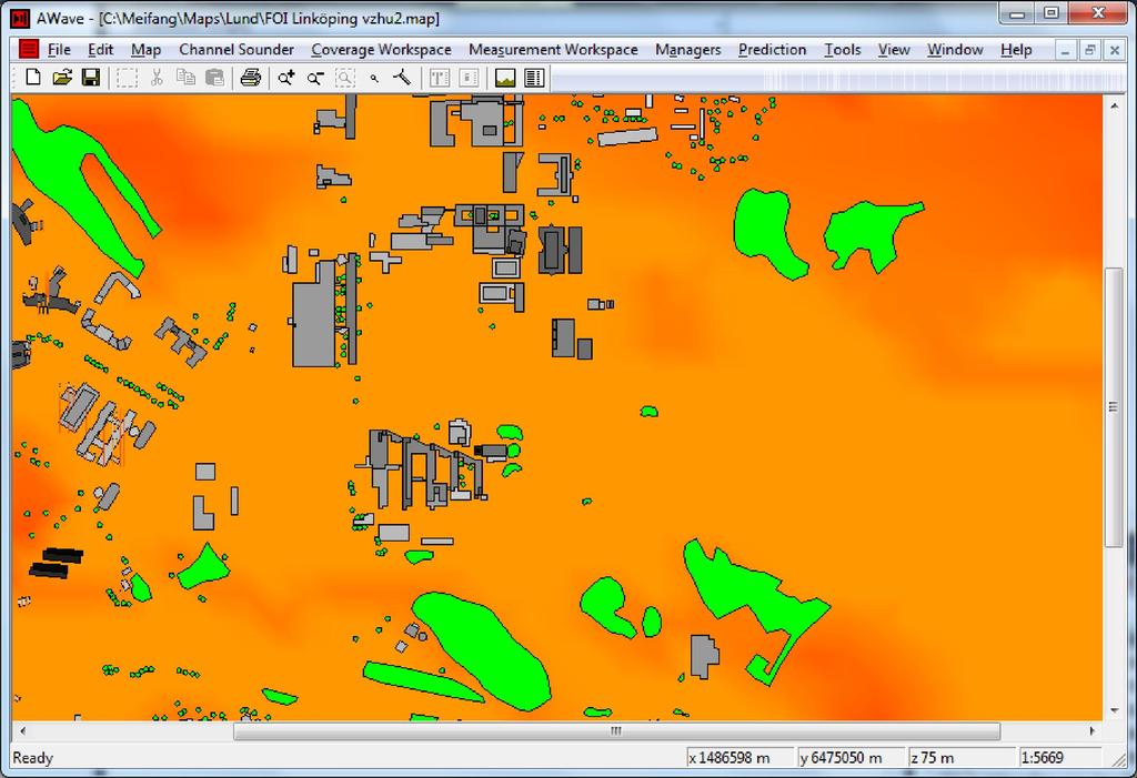
36 Digital 3D map of the environment
37 Visualized paths for a particular Tx/Rx position
38 Interaction points, 20 strongest MPCs LOS NLOS Radius of circles reflects power, color reflects delay
39 Interaction points, 20 strongest MPCs NLOS NLOS Radius of circles reflects power, color reflects delay
40 Multipath components tend to appear in clusters, moving Rx Dead cluster As Rx is moving (10 wavelengths, approximately 10 meters), clusters disappear and new clusters appear. Active clusters during the Rx movement New cluster
EITN85, FREDRIK TUFVESSON ELECTRICAL AND INFORMATION TECHNOLOGY
 Wireless Communication Channels Lecture 2: Propagation mechanisms EITN85, FREDRIK TUFVESSON ELECTRICAL AND INFORMATION TECHNOLOGY Contents Free space loss Propagation mechanisms Transmission Reflection
Chapter 4. Propagation effects. Slides for Wireless Communications Edfors, Molisch, Tufvesson
 Chapter 4 Propagation effects Why channel modelling? The performance of a radio system is ultimately determined by the radio channel The channel models basis for system design algorithm design antenna
Propagation mechanisms
 RADIO SYSTEMS ETIN15 Lecture no: 2 Propagation mechanisms Ove Edfors, Department of Electrical and Information Technology Ove.Edfors@eit.lth.se Contents Short on db calculations Basics about antennas Propagation
Propagation Mechanism
 Propagation Mechanism ELE 492 FUNDAMENTALS OF WIRELESS COMMUNICATIONS 1 Propagation Mechanism Simplest propagation channel is the free space: Tx free space Rx In a more realistic scenario, there may be
Noise and Propagation mechanisms
 2 Noise and Propagation mechanisms Noise Johnson-Nyquist noise Physical review 1928 V rms2 = 4kTBR k : Bolzmann s constant T : absolute temperature B : bandwidth R : Resistance P=4kTB 1 1 Why is this a
Channel Modelling ETIM10. Channel models
 Channel Modelling ETIM10 Lecture no: 6 Channel models Fredrik Tufvesson Department of Electrical and Information Technology Lund University, Sweden Fredrik.Tufvesson@eit.lth.se 2012-02-03 Fredrik Tufvesson
UWB Channel Modeling
 Channel Modeling ETIN10 Lecture no: 9 UWB Channel Modeling Fredrik Tufvesson & Johan Kåredal, Department of Electrical and Information Technology fredrik.tufvesson@eit.lth.se 2011-02-21 Fredrik Tufvesson
Channel Modeling ETI 085
 Channel Modeling ETI 085 Overview Lecture no: 9 What is Ultra-Wideband (UWB)? Why do we need UWB channel models? UWB Channel Modeling UWB channel modeling Standardized UWB channel models Fredrik Tufvesson
EITN85, FREDRIK TUFVESSON, JOHAN KÅREDAL ELECTRICAL AND INFORMATION TECHNOLOGY. Why do we need UWB channel models?
 Wireless Communication Channels Lecture 9:UWB Channel Modeling EITN85, FREDRIK TUFVESSON, JOHAN KÅREDAL ELECTRICAL AND INFORMATION TECHNOLOGY Overview What is Ultra-Wideband (UWB)? Why do we need UWB channel
Mobile Radio Propagation Channel Models
 Wireless Information Transmission System Lab. Mobile Radio Propagation Channel Models Institute of Communications Engineering National Sun Yat-sen University Table of Contents Introduction Propagation
The Radio Channel. COS 463: Wireless Networks Lecture 14 Kyle Jamieson. [Parts adapted from I. Darwazeh, A. Goldsmith, T. Rappaport, P.
 The Radio Channel COS 463: Wireless Networks Lecture 14 Kyle Jamieson [Parts adapted from I. Darwazeh, A. Goldsmith, T. Rappaport, P. Steenkiste] Motivation The radio channel is what limits most radio
EITN85, FREDRIK TUFVESSON ELECTRICAL AND INFORMATION TECHNOLOGY
 Wireless Communication Channels Lecture 6: Channel Models EITN85, FREDRIK TUFVESSON ELECTRICAL AND INFORMATION TECHNOLOGY Content Modelling methods Okumura-Hata path loss model COST 231 model Indoor models
Mobile Communications
 Mobile Communications Part IV- Propagation Characteristics Professor Z Ghassemlooy School of Computing, Engineering and Information Sciences University of Northumbria U.K. http://soe.unn.ac.uk/ocr Contents
Revision of Lecture One
 Revision of Lecture One System blocks and basic concepts Multiple access, MIMO, space-time Transceiver Wireless Channel Signal/System: Bandpass (Passband) Baseband Baseband complex envelope Linear system:
Antennas and Propagation. Chapter 6a: Propagation Definitions, Path-based Modeling
 Antennas and Propagation a: Propagation Definitions, Path-based Modeling Introduction Propagation How signals from antennas interact with environment Goal: model channel connecting TX and RX Antennas and
Path-loss and Shadowing (Large-scale Fading) PROF. MICHAEL TSAI 2015/03/27
 PROF. MICHAEL TSAI 2015/03/27") Path-loss and Shadowing (Large-scale Fading) PROF. MICHAEL TSAI 2015/03/27 Multipath 2 3 4 5 Friis Formula TX Antenna RX Antenna = 4 EIRP= Power spatial density 1 4 6 Antenna Aperture = 4 Antenna Aperture=Effective
Path-loss and Shadowing (Large-scale Fading) PROF. MICHAEL TSAI 2015/03/27 Multipath 2 3 4 5 Friis Formula TX Antenna RX Antenna = 4 EIRP= Power spatial density 1 4 6 Antenna Aperture = 4 Antenna Aperture=Effective
Revision of Lecture One
 Revision of Lecture One System block Transceiver Wireless Channel Signal / System: Bandpass (Passband) Baseband Baseband complex envelope Linear system: complex (baseband) channel impulse response Channel:
Session2 Antennas and Propagation
 Wireless Communication Presented by Dr. Mahmoud Daneshvar Session2 Antennas and Propagation 1. Introduction Types of Anttenas Free space Propagation 2. Propagation modes 3. Transmission Problems 4. Fading
5G Antenna Design & Network Planning
 5G Antenna Design & Network Planning Challenges for 5G 5G Service and Scenario Requirements Massive growth in mobile data demand (1000x capacity) Higher data rates per user (10x) Massive growth of connected
Channel models and antennas
 RADIO SYSTEMS ETIN15 Lecture no: 4 Channel models and antennas Ove Edfors, Department of Electrical and Information Technology Ove.Edfors@eit.lth.se 2012-03-21 Ove Edfors - ETIN15 1 Contents Why do we
ELEG 5693 Wireless Communications Propagation and Noise Part I
 Department of Electrical Engineering University of Arkansas ELEG 5693 Wireless Communications ropagation and Noise art I Dr. Jingxian Wu wuj@uark.edu OULINE 2 Wireless channel ath loss Shadowing Small
Simulation of Outdoor Radio Channel
 Simulation of Outdoor Radio Channel Peter Brída, Ján Dúha Department of Telecommunication, University of Žilina Univerzitná 815/1, 010 6 Žilina Email: brida@fel.utc.sk, duha@fel.utc.sk Abstract Wireless
ECE 476/ECE 501C/CS Wireless Communication Systems Winter Lecture 6: Fading
 ECE 476/ECE 501C/CS 513 - Wireless Communication Systems Winter 2004 Lecture 6: Fading Last lecture: Large scale propagation properties of wireless systems - slowly varying properties that depend primarily
Radio channel modeling: from GSM to LTE
 Radio channel modeling: from GSM to LTE and beyond Alain Sibille Telecom ParisTech Comelec / RFM Outline Introduction: why do we need channel models? Basics Narrow band channels Wideband channels MIMO
ECE 476/ECE 501C/CS Wireless Communication Systems Winter Lecture 6: Fading
 ECE 476/ECE 501C/CS 513 - Wireless Communication Systems Winter 2005 Lecture 6: Fading Last lecture: Large scale propagation properties of wireless systems - slowly varying properties that depend primarily
ECE 476/ECE 501C/CS Wireless Communication Systems Winter Lecture 6: Fading
 ECE 476/ECE 501C/CS 513 - Wireless Communication Systems Winter 2003 Lecture 6: Fading Last lecture: Large scale propagation properties of wireless systems - slowly varying properties that depend primarily
Antennas & Propagation. CSG 250 Fall 2007 Rajmohan Rajaraman
 Antennas & Propagation CSG 250 Fall 2007 Rajmohan Rajaraman Introduction An antenna is an electrical conductor or system of conductors o Transmission - radiates electromagnetic energy into space o Reception
Review of Path Loss models in different environments
 Review of Path Loss models in different environments Mandeep Kaur 1, Deepak Sharma 2 1 Computer Scinece, Kurukshetra Institute of Technology and Management, Kurukshetra 2 H.O.D. of CSE Deptt. Abstract
Channel modelling repetition
 Channel Modelling ETIM10 Lecture no: 11 Channel modelling repetition Fredrik Tufvesson Department of Electrical and Information Technology Lund University, Sweden Fredrik.Tufvesson@eit.lth.se 011-03-01
RECOMMENDATION ITU-R P The prediction of the time and the spatial profile for broadband land mobile services using UHF and SHF bands
 Rec. ITU-R P.1816 1 RECOMMENDATION ITU-R P.1816 The prediction of the time and the spatial profile for broadband land mobile services using UHF and SHF bands (Question ITU-R 211/3) (2007) Scope The purpose
Results from a MIMO Channel Measurement at 300 MHz in an Urban Environment
 Measurement at 0 MHz in an Urban Environment Gunnar Eriksson, Peter D. Holm, Sara Linder and Kia Wiklundh Swedish Defence Research Agency P.o. Box 1165 581 11 Linköping Sweden firstname.lastname@foi.se
EEG 816: Radiowave Propagation 2009
 Student Matriculation No: Name: EEG 816: Radiowave Propagation 2009 Dr A Ogunsola This exam consists of 5 problems. The total number of pages is 5, including the cover page. You have 2.5 hours to solve
Channel models and antennas
 RADIO SYSTEMS ETIN15 Lecture no: 4 Channel models and antennas Anders J Johansson, Department of Electrical and Information Technology anders.j.johansson@eit.lth.se 29 March 2017 1 Contents Why do we need
Mobile Radio Wave propagation channel- Path loss Models
 Mobile Radio Wave propagation channel- Path loss Models 3.1 Introduction The wireless Communication is one of the integral parts of society which has been a focal point for sharing information with different
UNIK4230: Mobile Communications Spring 2013
 UNIK4230: Mobile Communications Spring 2013 Abul Kaosher abul.kaosher@nsn.com Mobile: 99 27 10 19 1 UNIK4230: Mobile Communications Propagation characteristis of wireless channel Date: 07.02.2013 2 UNIK4230:
Wireless Communication System
 Wireless Communication System Generic Block Diagram An t PC An r Source Tx Rx Destination P t G t L p G r P r Source a source of information to be transmitted Destination a destination of the transmitted
Channel Models. Spring 2017 ELE 492 FUNDAMENTALS OF WIRELESS COMMUNICATIONS 1
 Channel Models Spring 2017 ELE 492 FUNDAMENTALS OF WIRELESS COMMUNICATIONS 1 Narrowband Channel Models Statistical Approach: Impulse response modeling: A narrowband channel can be represented by an impulse
Wireless Physical Layer Concepts: Part II
 Wireless Physical Layer Concepts: Part II Raj Jain Professor of CSE Washington University in Saint Louis Saint Louis, MO 63130 Jain@cse.wustl.edu Audio/Video recordings of this lecture are available at:
UHF Radio Frequency Propagation Model for Akure Metropolis
 Abstract Research Journal of Engineering Sciences ISSN 2278 9472 UHF Radio Frequency Propagation Model for Akure Metropolis Famoriji J.O. and Olasoji Y.O. Federal University of Technology, Akure, Nigeria
Antennas and Propagation
 CMPE 477 Wireless and Mobile Networks Lecture 3: Antennas and Propagation Antennas Propagation Modes Line of Sight Transmission Fading in the Mobile Environment Introduction An antenna is an electrical
5.9 GHz V2X Modem Performance Challenges with Vehicle Integration
 5.9 GHz V2X Modem Performance Challenges with Vehicle Integration October 15th, 2014 Background V2V DSRC Why do the research? Based on 802.11p MAC PHY ad-hoc network topology at 5.9 GHz. Effective Isotropic
Millimeter Wave Small-Scale Spatial Statistics in an Urban Microcell Scenario
 Millimeter Wave Small-Scale Spatial Statistics in an Urban Microcell Scenario Shu Sun, Hangsong Yan, George R. MacCartney, Jr., and Theodore S. Rappaport {ss7152,hy942,gmac,tsr}@nyu.edu IEEE International
Rec. ITU-R P RECOMMENDATION ITU-R P PROPAGATION BY DIFFRACTION. (Question ITU-R 202/3)
") Rec. ITU-R P.- 1 RECOMMENDATION ITU-R P.- PROPAGATION BY DIFFRACTION (Question ITU-R 0/) Rec. ITU-R P.- (1-1-1-1-1-1-1) The ITU Radiocommunication Assembly, considering a) that there is a need to provide
Rec. ITU-R P.- 1 RECOMMENDATION ITU-R P.- PROPAGATION BY DIFFRACTION (Question ITU-R 0/) Rec. ITU-R P.- (1-1-1-1-1-1-1) The ITU Radiocommunication Assembly, considering a) that there is a need to provide
Project = An Adventure : Wireless Networks. Lecture 4: More Physical Layer. What is an Antenna? Outline. Page 1
 Project = An Adventure 18-759: Wireless Networks Checkpoint 2 Checkpoint 1 Lecture 4: More Physical Layer You are here Done! Peter Steenkiste Departments of Computer Science and Electrical and Computer
Written Exam Channel Modeling for Wireless Communications - ETIN10
 Written Exam Channel Modeling for Wireless Communications - ETIN10 Department of Electrical and Information Technology Lund University 2017-03-13 2.00 PM - 7.00 PM A minimum of 30 out of 60 points are
Channel Modeling and Characteristics
 Channel Modeling and Characteristics Dr. Farid Farahmand Updated:10/15/13, 10/20/14 Line-of-Sight Transmission (LOS) Impairments The received signal is different from the transmitted signal due to transmission
Rec. ITU-R P RECOMMENDATION ITU-R P *
 Rec. ITU-R P.682-1 1 RECOMMENDATION ITU-R P.682-1 * PROPAGATION DATA REQUIRED FOR THE DESIGN OF EARTH-SPACE AERONAUTICAL MOBILE TELECOMMUNICATION SYSTEMS (Question ITU-R 207/3) Rec. 682-1 (1990-1992) The
Channel Modelling ETIN10. Directional channel models and Channel sounding
 Channel Modelling ETIN10 Lecture no: 7 Directional channel models and Channel sounding Ghassan Dahman / Fredrik Tufvesson Department of Electrical and Information Technology Lund University, Sweden 2014-02-17
Point to point Radiocommunication
 Point to point Radiocommunication SMS4DC training seminar 7 November 1 December 006 1 Technical overview Content SMS4DC Software link calculation Exercise 1 Point-to-point Radiocommunication Link A Radio
Propagation Modelling White Paper
 Propagation Modelling White Paper Propagation Modelling White Paper Abstract: One of the key determinants of a radio link s received signal strength, whether wanted or interfering, is how the radio waves
Chapter 15: Radio-Wave Propagation
 Chapter 15: Radio-Wave Propagation MULTIPLE CHOICE 1. Radio waves were first predicted mathematically by: a. Armstrong c. Maxwell b. Hertz d. Marconi 2. Radio waves were first demonstrated experimentally
Antennas and Propagation. Chapter 5
 Antennas and Propagation Chapter 5 Introduction An antenna is an electrical conductor or system of conductors Transmission - radiates electromagnetic energy into space Reception - collects electromagnetic
Antennas and Propagation
 Mobile Networks Module D-1 Antennas and Propagation 1. Introduction 2. Propagation modes 3. Line-of-sight transmission 4. Fading Slides adapted from Stallings, Wireless Communications & Networks, Second
Project: IEEE P Working Group for Wireless Personal Area Networks N
 Project: IEEE P82.15 Working Group for Wireless Personal Area Networks N (WPANs( WPANs) Title: [UWB Channel Model for Indoor Residential Environment] Date Submitted: [2 September, 24] Source: [Chia-Chin
PROPAGATION MODELING 4C4
 PROPAGATION MODELING ledoyle@tcd.ie 4C4 http://ledoyle.wordpress.com/temp/ Classification Band Initials Frequency Range Characteristics Extremely low ELF < 300 Hz Infra low ILF 300 Hz - 3 khz Ground wave
Antennas and Propagation. Chapter 5
 Antennas and Propagation Chapter 5 Introduction An antenna is an electrical conductor or system of conductors Transmission - radiates electromagnetic energy into space Reception - collects electromagnetic
λ iso d 4 π watt (1) + L db (2)
 + L db (2)") 1 Path-loss Model for Broadcasting Applications and Outdoor Communication Systems in the VHF and UHF Bands Constantino Pérez-Vega, Member IEEE, and José M. Zamanillo Communications Engineering Department
1 Path-loss Model for Broadcasting Applications and Outdoor Communication Systems in the VHF and UHF Bands Constantino Pérez-Vega, Member IEEE, and José M. Zamanillo Communications Engineering Department
Radio Propagation Fundamentals
 Radio Propagation Fundamentals Concept of Electromagnetic Wave Propagation Mechanisms Modes of Propagation Propagation Models Path Profiles Link Budget Fading Channels Electromagnetic (EM) Waves EM Wave
Wireless Communication Technologies Course No. 16:332:559 (Spring 2000) Lecture Lalitha Sankaranarayanan
 Lecture Lalitha Sankaranarayanan") Wireless Communication Technologies Course No. 6:33:559 (Spring 000) Lecture 0-6-00 Lalitha Sankaranarayanan lalitha@ustad.att.com PATH LOSS IN MACROCELLS: The theoretical model for path loss, L p, for
Wireless Communication Technologies Course No. 6:33:559 (Spring 000) Lecture 0-6-00 Lalitha Sankaranarayanan lalitha@ustad.att.com PATH LOSS IN MACROCELLS: The theoretical model for path loss, L p, for
(Refer Slide Time: 00:01:31 min)
") Wireless Communications Dr. Ranjan Bose Department of Electrical Engineering Indian Institute of Technology, Delhi Lecture No. # 12 Mobile Radio Propagation (Continued) We will start today s lecture with
Wireless Communications Dr. Ranjan Bose Department of Electrical Engineering Indian Institute of Technology, Delhi Lecture No. # 12 Mobile Radio Propagation (Continued) We will start today s lecture with
The prediction of the time and the spatial profile for broadband land mobile services using UHF and SHF bands
 Recommendation ITU-R P.1816-3 (7/15) The prediction of the time and the spatial profile for broadband land mobile services using UHF and SHF bands P Series Radiowave propagation ii Rec. ITU-R P.1816-3
RADIOWAVE PROPAGATION
 RADIOWAVE PROPAGATION Physics and Applications CURT A. LEVIS JOEL T. JOHNSON FERNANDO L. TEIXEIRA The cover illustration is part of a figure from R.C. Kirby, "Introduction," Lecture 1 in NBS Course in
# DEFINITIONS TERMS. 2) Electrical energy that has escaped into free space. Electromagnetic wave
 Electrical energy that has escaped into free space. Electromagnetic wave") CHAPTER 14 ELECTROMAGNETIC WAVE PROPAGATION # DEFINITIONS TERMS 1) Propagation of electromagnetic waves often called radio-frequency (RF) propagation or simply radio propagation. Free-space 2) Electrical
CHAPTER 14 ELECTROMAGNETIC WAVE PROPAGATION # DEFINITIONS TERMS 1) Propagation of electromagnetic waves often called radio-frequency (RF) propagation or simply radio propagation. Free-space 2) Electrical
CHAPTER 6 THE WIRELESS CHANNEL
 CHAPTER 6 THE WIRELESS CHANNEL These slides are made available to faculty in PowerPoint form. Slides can be freely added, modified, and deleted to suit student needs. They represent substantial work on
Experimental Evaluation Scheme of UWB Antenna Performance
 Tokyo Tech. Experimental Evaluation Scheme of UWB Antenna Performance Sathaporn PROMWONG Wataru HACHITANI Jun-ichi TAKADA TAKADA-Laboratory Mobile Communication Research Group Graduate School of Science
Antennas Multiple antenna systems
 Channel Modelling ETIM10 Lecture no: 8 Antennas Multiple antenna systems Fredrik Tufvesson Department of Electrical and Information Technology Lund University, Sweden Fredrik.Tufvesson@eit.lth.se 2012-02-13
Basic Propagation Theory
 S-7.333 POSTGRADUATE COURSE IN RADIO COMMUNICATIONS, AUTUMN 4 1 Basic Propagation Theory Fabio Belloni S-88 Signal Processing Laboratory, HUT fbelloni@hut.fi Abstract In this paper we provide an introduction
Mobile Hata Model and Walkfisch Ikegami
 Calculate Path Loss in Transmitter in Global System Mobile By Using Hata Model and Ikegami Essam Ayiad Ashebany 1, Silaiman Khalifa Yakhlef 2 and A. R. Zerek 3 1 Post grade Student, Libyan Academy of Graduate
Basic Radio Physics. Developed by Sebastian Buettrich. ItrainOnline MMTK 1
 Basic Radio Physics Developed by Sebastian Buettrich 1 Goals Understand radiation/waves used in wireless networking. Understand some basic principles of their behaviour. Apply this understanding to real
Chapter 4 DOA Estimation Using Adaptive Array Antenna in the 2-GHz Band
 Chapter 4 DOA Estimation Using Adaptive Array Antenna in the 2-GHz Band 4.1. Introduction The demands for wireless mobile communication are increasing rapidly, and they have become an indispensable part
White paper. Long range metering systems : VHF or UHF?
 ALCIOM 5, Parvis Robert Schuman 92370 CHAVILLE - FRANCE Tel/Fax : 01 47 09 30 51 contact@alciom.com www.alciom.com Project : White paper DOCUMENT : Long range metering systems : VHF or UHF? REFERENCE :
Antennas and Propagation
 Antennas and Propagation Chapter 5 Introduction An antenna is an electrical conductor or system of conductors Transmission - radiates electromagnetic energy into space Reception - collects electromagnetic
Autumn Main Exam SEAT NUMBER: STUDENTNUMBER: L--- ~~--~--~--~----~--~--L-~ SURNAME: (FAMILY NAME) OTHER NAMES: LECTURER NAME:
 OTHER NAMES: LECTURER NAME:") Autumn 216- Main Exam SEAT NUMBER: iuts UNIVERSITY OF TECHNOLOGY SYDNEY STUDENTNUMBER: L--- ~~--~--~--~----~--~--L-~ SURNAME: (FAMILY NAME) OTHER NAMES: LECTURER NAME: This paper and all materials issued
Autumn 216- Main Exam SEAT NUMBER: iuts UNIVERSITY OF TECHNOLOGY SYDNEY STUDENTNUMBER: L--- ~~--~--~--~----~--~--L-~ SURNAME: (FAMILY NAME) OTHER NAMES: LECTURER NAME: This paper and all materials issued
SHORT RANGE PROPAGATION MODEL FOR A VERY WIDEBAND DIRECTIVE CHANNEL AT 5.5 GHZ BAND
 Progress In Electromagnetics Research, Vol. 130, 319 346, 2012 SHORT RANGE PROPAGATION MODEL FOR A VERY WIDEBAND DIRECTIVE CHANNEL AT 5.5 GHZ BAND B. Taha Ahmed *, D. F. Campillo, and J. L. Masa Campos
RECOMMENDATION ITU-R F.1819
 Rec. ITU-R F.1819 1 RECOMMENDATION ITU-R F.1819 Protection of the radio astronomy service in the 48.94-49.04 GHz band from unwanted emissions from HAPS in the 47.2-47.5 GHz and 47.9-48.2 GHz bands * (2007)
Terrain Reflection and Diffraction, Part One
 Terrain Reflection and Diffraction, Part One 1 UHF and VHF paths near the ground 2 Propagation over a plane Earth 3 Fresnel zones Levis, Johnson, Teixeira (ESL/OSU) Radiowave Propagation August 17, 2018
Lecture 1 Wireless Channel Models
 MIMO Communication Systems Lecture 1 Wireless Channel Models Prof. Chun-Hung Liu Dept. of Electrical and Computer Engineering National Chiao Tung University Spring 2017 2017/3/2 Lecture 1: Wireless Channel
TEMPUS PROJECT JEP Wideband Analysis of the Propagation Channel in Mobile Broadband System
 Department of Electrical Engineering and Computer Science TEMPUS PROJECT JEP 743-94 Wideband Analysis of the Propagation Channel in Mobile Broadband System Krzysztof Jacek Kurek Final report Supervisor:
Propagation Channels. Chapter Path Loss
 Chapter 9 Propagation Channels The transmit and receive antennas in the systems we have analyzed in earlier chapters have been in free space with no other objects present. In a practical communication
EKT 450 Mobile Communication System
 EKT 450 Mobile Communication System Chapter 2: Mobile Radio Propagation Characteristics Dr. Azremi Abdullah Al-Hadi School of Computer and Communication Engineering azremi@unimap.edu.my 1 Introduction
Introduction to wireless systems
 Introduction to wireless systems Wireless Systems a.a. 2014/2015 Un. of Rome La Sapienza Chiara Petrioli Department of Computer Science University of Rome Sapienza Italy Background- Wireless Systems What
UNIT Derive the fundamental equation for free space propagation?
 UNIT 8 1. Derive the fundamental equation for free space propagation? Fundamental Equation for Free Space Propagation Consider the transmitter power (P t ) radiated uniformly in all the directions (isotropic),
The MYTHOLOGIES OF WIRELESS COMMUNICATION. Tapan K Sarkar
 The MYTHOLOGIES OF WIRELESS COMMUNICATION Tapan K Sarkar What is an Antenna? A device whose primary purpose is to radiate or receive electromagnetic energy What is Radiation? Far Field (Fraunhofer region>2l
CALIFORNIA STATE UNIVERSITY, NORTHRIDGE FADING CHANNEL CHARACTERIZATION AND MODELING
 CALIFORNIA STATE UNIVERSITY, NORTHRIDGE FADING CHANNEL CHARACTERIZATION AND MODELING A graduate project submitted in partial fulfillment of the requirements For the degree of Master of Science in Electrical
Groundwave Propagation, Part One
 Groundwave Propagation, Part One 1 Planar Earth groundwave 2 Planar Earth groundwave example 3 Planar Earth elevated antenna effects Levis, Johnson, Teixeira (ESL/OSU) Radiowave Propagation August 17,
Overview. Copyright Remcom Inc. All rights reserved.
 Overview Remcom: Who We Are EM market leader, with innovative simulation and wireless propagation tools since 1994 Broad business base Span Commercial and Government contracting International presence:
Site-Specific Validation of ITU Indoor Path Loss Model at 2.4 GHz
 Site-Specific Validation of ITU Indoor Path Loss Model at 2.4 GHz Theofilos Chrysikos (1), Giannis Georgopoulos (1) and Stavros Kotsopoulos (1) (1) Wireless Telecommunications Laboratory Department of
Radio propagation modeling on 433 MHz
 Ákos Milánkovich 1, Károly Lendvai 1, Sándor Imre 1, Sándor Szabó 1 1 Budapest University of Technology and Economics, Műegyetem rkp. 3-9. 1111 Budapest, Hungary {milankovich, lendvai, szabos, imre}@hit.bme.hu
EEM.Ant. Antennas and Propagation
 EEM.ant/0304/08pg/Req: None 1/8 UNIVERSITY OF SURREY Department of Electronic Engineering MSc EXAMINATION EEM.Ant Antennas and Propagation Duration: 2 Hours Spring 2003/04 READ THESE INSTRUCTIONS Answer
Link Budget Calculation
 Link Budget Calculation Training materials for wireless trainers This 60 minute talk is about estimating wireless link performance by using link budget calculations. It also introduces the Radio Mobile
Study of Factors which affect the Calculation of Co- Channel Interference in a Radio Link
 International Journal of Electronic and Electrical Engineering. ISSN 0974-2174 Volume 8, Number 2 (2015), pp. 103-111 International Research Publication House http://www.irphouse.com Study of Factors which
Lecture 7/8: UWB Channel. Kommunikations
 Lecture 7/8: UWB Channel Kommunikations Technik UWB Propagation Channel Radio Propagation Channel Model is important for Link level simulation (bit error ratios, block error ratios) Coverage evaluation
Unit 3 - Wireless Propagation and Cellular Concepts
 X Courses» Introduction to Wireless and Cellular Communications Unit 3 - Wireless Propagation and Cellular Concepts Course outline How to access the portal Assignment 2. Overview of Cellular Evolution
Near-Earth Propagation Models
 CHAPTER 7 Near-Earth Propagation Models 7.1 INTRODUCTION Many applications require RF or microwave propagation from point to point very near the earth s surface and in the presence of various impairments.
LMS4000 & NCL MHz Radio Propagation
 LMS4000 & NCL1900 900-MHz Radio Propagation This application note is an update to the previous LMS3000/LMS3100 900 MHz Radio Propagation note. It provides general guidelines to estimate CCU3000 & NCL1900
Indoor Path Loss Modeling and Measurements at 2.44 GHz
 Indoor Path Loss Modeling and Measurements at 2.44 GHz Alaleh Mashkouri Najafi Master Thesis Stockholm, Sweden 2012 XR-EE-ETK 2012:002 KTH Royal Institute of Technology M. Sc. in Wireless Systems Indoor
Antennas and Propagation. Prelude to Chapter 4 Propagation
 Antennas and Propagation Prelude to Chapter 4 Propagation Introduction An antenna is an electrical conductor or system of conductors for: Transmission - radiates electromagnetic energy into space (involves
Evaluation of Power Budget and Cell Coverage Range in Cellular GSM System
 Evaluation of Power Budget and Cell Coverage Range in Cellular GSM System Dr. S. A. Mawjoud samialmawjoud_2005@yahoo.com Abstract The paper deals with study of affecting parameters on the communication
Colubris Networks. Antenna Guide
 Colubris Networks Antenna Guide Creation Date: February 10, 2006 Revision: 1.0 Table of Contents 1. INTRODUCTION... 3 2. ANTENNA TYPES... 3 2.1. OMNI-DIRECTIONAL ANTENNA... 3 2.2. DIRECTIONAL ANTENNA...
Supporting Network Planning Tools II
 Session 5.8 Supporting Network Planning Tools II Roland Götz LS telcom AG / Spectrocan 1 Modern Radio Network Planning Tools Radio Network Planning Tool Data / Result Output Data Management Network Processor