The MYTHOLOGIES OF WIRELESS COMMUNICATION. Tapan K Sarkar
|
|
|
- Kerry Barnett
- 5 years ago
- Views:
Transcription
1 The MYTHOLOGIES OF WIRELESS COMMUNICATION Tapan K Sarkar
2 What is an Antenna? A device whose primary purpose is to radiate or receive electromagnetic energy What is Radiation? Far Field (Fraunhofer region>2l 2 /) the fields are transverse the shape of the field pattern is independent of the distance 2
3 What is the Near- Field (Fresnel region)? The near field is in the region D < 2 L 2 / Near Field: power is complex (need both E & H ) Far Field Real Power: need either E or H PROPERTIES OF NEAR FIELD For a Dipole E z = j30i m [exp( jkr 1 )/R 1 + exp( jkr 2 )/R 2 2 cos(kh)exp(-jk )/] The near field can never be zero for a dipole!!!! Only the far field has pattern nulls!! 3
4 What is the Far- Field? D > 2 L 2 / : L Antenna region What is the far field of a half wave dipole for =0.3m (1GHz)? 20, /0.3=0.15m What is the far field when the half wave dipole is 20 m above an infinite ground plane at =1m? Equivalently if the dipole is on the top of a 20 m tower above a perfect ground plane? 24040/0.3=10, km 4
5 The radiation pattern of a half wave dipole in free space (only one fourth shown) 5

6 Unit: db 6
7 Antenna Pattern from 0 to 5 degree elevation 7
8
9 20m Different transmitting dipole configurations at a height of 20 m, 20 m tilted downwards at an angle of 11, 10 m, 2 m and 1 m tilted upwards by an angle of 1 above the ground plane. The receiving dipole is located at 2 m above the ground plane and at a horizontal distance of 100 m from the transmitter. 10m 2m 2m 1m 100 m 9
10 Plot of the variation of the channel capacity as a function of the height of the transmitting antenna above a perfectly conducting earth, for a fixed height of 2 m for the receiving antenna. 10
11 Different transmitting dipole configurations at a height of 20 m, 20 m tilted downwards at an angle of 11, 10 m, 2 m and 1 m tilted upwards by an angle of 1 above the ground plane. The receiving dipole is located at 2 m above the ground plane and at a horizontal distance of 100 m from the transmitter. The receiving dipole is enclosed by a dielectric shell.
12 Comparison of the plots of the variation of the channel capacity as a function of the height of the transmitting antenna above a perfectly conducting earth, for a fixed height of 2 m for the receiving antenna. LOS stands for line-of-sight. 12

13 IEEE SPECTRUM Magazine, October 2010, pp. 29
14
15 Transmitter 1 100W/m 2 There will be constructive and destructive interference. So what will be the variation of power? Transmitter 2 1W/m 2 (100 ± 1) W/m 2?? 15
16 2 3V 1 Power Dissipated in 1 = I 2 R = 1 2 6V 1 Power Dissipated in 1 = I 2 R = = 4 2 3V 6V 1 Applied Superposition Power Dissipated in 1 = I 2 R = = 9 Power Superposition does not work in electrical engineering! 16
17 2 3V 6V 1 Applied Superposition Power Dissipated in 1 = I 2 R = = 49 Power Superposition does not work in electrical engineering! Only Superposition of the VOLTAGES and the CURRENTS are allowed!! 17
18 In electrical engineering, unlike mechanical engineering, it is vector in nature! ONLY VOLTAGES AND CURRENTS CAN BE SUPERIMPOSED AND NOT POWER! THAT IS WHY WE CALL EE FIELD THEORY. The field quantities expressed by the electric and magnetic fields are related to voltage and current, respectively. The fields add up not power
19 Transmitter 1 100W Field 2 E E Interference occur between the fields E1 and E2. So the variation in field is 2 (10 1) Transmitter 2 1W 2 E2 1 2 E Therefore the variation in the power due to interference is 121W 81W!! 19 19

20 Shannon s Capacity for a Single Channel C Blog 1 P / N 2 Extension of Shannon Channel Capacity to multichannel system (like MIMO) C M M Blog2 1 P M N This equation is often used to claim that a MIMO is better than a SISO! Does it make sense? Power superposition is not applicable in electrical engineering!!! 20
21 Dennis Gabor wrote:[1952, IEEE Trans on Information Theory, First Issue] The wireless communication systems are due to the generation, reception and transmission of electro-magnetic signals. Therefore all wireless systems are subject to the general laws of radiation. Communication theory has up to now been developed mainly along mathematical lines, taking for granted the physical significance of the quantities which are fundamental in its formalism. But communication is the transmission of physical effects from one system to another. Hence communication theory should be considered as a branch of physics. 21
22 Channel Capacity Shannon Formula C S B PS log2 1 PN Use signal power and noise power Does not represent near-field behavior of the signals Under the constraint that the average radiated power is constant
23 freq= 1GHz = 30 cm Radius of wire= Transmitter Receiver 100 m /2 h 23
24 Variation of Channel Capacity with the height of the Tx antenna 24
25 Load on the received antenna (Rx Ant HT =2M) Tx Ant Ht Case 1: 50 Case 2: Matched Free Space j 45.4 h = 15 cm j 45.4 h = 1 m j 45.4 h= 10 m j 45.4 h= 20 m j
26 Magnitude of the Received Power Capacity defined by log2(ratio) U M 0 0 C =C 0.28B Free space Case 1 [W] Case 2 [W] C 0 U = C 0 M 0.28B C 0 M 26
27 For S/N 128 or 21.2 db log 2 (S/N) log 2 (2 7 ) 7 Compare 7B to 0.28B for the capacity. CONCLUSION: ELECTROMAGNETIC PRINCIPLES of MATCHING DEVICES THEREFORE ARE IRRELEVANT!!! 27
28 MIMO: A STAISTICAL ABERRATION?!? 28
29 METHODOLOGIES Using a Simplistic Thinking Using a Signal Processing Terminology Using Maxwell-Poynting Theory
30 Using a Simplistic Thinking T x C 1 C 2 > C 1 T x C 2 Z A = 93Ω Z A Z A Z A Z A /2
31 Using a Signal Processing Terminology M T x X Input N R x Y Output Y H X H N1 NM M1 Transfer function matrix
32 x 1 h 11 y 1 x 2 y 2 x NT h N N R T y NR A MIMO System 32
33 Using a Signal Processing Terminology In general is a DIAGONAL MATRIX H H H H U V with U U [ I ] and V V [ I ] H Y U V X H H Y U Y X V X H X V X X V X H Y U Y Y U Y H H Y X V X X Y U Y Multiple Decoupled Spatial Channels Operating at the same FFREQUENCY
34 Using a Signal Processing Terminology The principle of MIMO Y X 2 y x 1 2 y x 2 There are multiple separate decoupled channels 2 y x y x Hence the conjecture simultaneous multiple transmission can be made H X V X Y U Y WIRELESS COMES IN
35 x 1 h 11 y 1 x 2 y 2 x NT h N N R T y NR A MIMO System 35
36 1 n 1 x x x + y y encoder decoder NR x Vx x + y H U y NR n NR y U H y U H Hx U H ( UΣV H ) x U H n H H y ΣV x U n y Σx n 36
37 Using a Maxwell-Poynting Theory 1 1 Good radiation +1 1 Lousy radiation Hence, even though simultaneous multiple channels are possible, only one is practical and the others are not very useful from a systems perspective
38 A typical 3 3 MIMO system consisting of half wave dipoles, half wavelength spaced and separated by 100 m.
39 SISO 11 MIMO 22 MIMO 33 MIMO 44 MIMO Ratio of the Square of the Singular Values for the Various Spatial MIMO Modes with Respect to the SISO Case (Broadside Orientation).
40 SISO 11 MIMO MIMO MIMO MIMO Ratio of the Square of the Singular Values for Various Spatial MIMO Modes with Respect to the SISO Case (Collinear Array Over a Ground Plane).
41 Received Power= 0.32 mw SISO SYSTEM Input Power=1W 41
42 22 MIMO SYSTEM 2 orthogonal spatial modes Mode 1: Excitation 1V; 1V Mode 2: Excitation 1V; 1V How does one get a feed to extract the two signals For the two orthogonal spatial modes? Received Power for each mode Mode 1: 1.4 mw Mode 2: 6.6 W Input Power=1W; for each spatial mode 42
43 C SISO B log P CMIMO B log21 B log21 2PN 2PN Observations: 1. The phased-array mode is the efficient one as expected over a SISO 2. One of the MIMO modes is a lousy radiator, that is why antenna engineers use only a single spatial mode 3. Channel has a linear increase; whereas power has a logarithmic increase N 43
44 SUPERPOSITION OF POWER!!! C s PS P 1 S 2 Blog21 log21 PN P N P S2 Even if is not suitable for a physical channel, dividing by P N might provide an useful theoretical number!!
45 Then comes the MYTHOLOGY!!! NEED A RICH MULTIPATH ENVIRONMENT FOR MIMO TO WORK! (What does this silly concept mean??) THIS CAN NEVER HAPPEN AS IT DOES NOT EXIST!!!!

46 Received Power = 18.2 mw SISO SYSTEM Input Power=1W 46

47 Received Power for each mode Mode 1: 13.1 mw Mode 2: 3.4 mw Input Power=1W; for each spatial mode 47
48 C B log B SISO 2 PN 3 times less 10 times less CMIMO B log21 B log21 2PN 2PN B? B? B 81.2 Observations: 1. Two inefficient radiating modes; yet the capacity is higher than a SISO 2. Two SISO is always better than a 22 MIMO under this nonphysical metric 3. There is a threshold effect as a function of Signal-to-noise ratio 48
49 SUMMARY: No Plane waves It is a Near Field Environment Can one define a multipath without a plane wave?
50
51
52
53
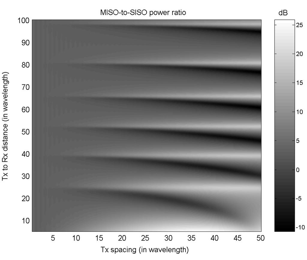
54 Transmitter 20 m Receiver D = distance from Tx to Rx 2 m PEC Ground MISO system setup; Transmitter is 20 m. above ground; Rx is 2 m. above ground; = transmitting antenna spacing; D = distance between the transmitter and the receiver. (For the SISO case, the transmitting antenna is placed at the center of the MISO transmitter.) 54
55 55
56 56
57
58 Inner dielectric: 3.5m3.5m3.5m; Outer dielectric: 3.8m3.8m 3.8m Dielectric thickness: 0.15m Dielectric constant : 2.5 # Near field: Spacing : m Frequency : 600MHz; Antenna size : λ/2 (0.25m) Antenna position : (0,0,0) 58
59 Free Space Inside a Dielectric Room The three components of the fields Er, Eθ, Eφ inside the room at x = 3.75λ, z = 3.75λ, as a function of y 59
60 FREE SPACE DIELECTRIC ROOM The three components of the fields Er, Eθ, Eφ inside the room at x = λ, z = 3.75λ, as a function of y 60
61 FREE SPACE DIELECTRIC ROOM The three components of the fields Er, Eθ, Eφ inside the room at x = 3.75λ, z = 0.198λ asa function of y. 61
62
63 Objective To illustrate that an electromagnetic macro modeling can properly predict the path loss exponent in a mobile cellular wireless communication system. Path loss exponent in a cellular wireless communication system is 3, preceded by a slow fading region, and followed by the fringe region where the path loss exponent is 4. Theoretical analysis: Radiation from a vertical dipole over a horizontal imperfect ground plane: Schelkunoff formulation. Experiments: Okumura et al. and more extensive experimental data from different base stations. 63
64 Point Source: Field decays as 1/R^2 : Power decays ar 1/R^4-10 Log10(P) - 40 db/decade Line Source: Field decays as 1/R : Power decays ar 1/R^2-20 db/decade Planar source:: Field decays as What type of a source has: Field decays as 1/R^1.5 : Power decays ar 1/R^3-30 db/decade
65
66 Prediction from Ericsson in-building path loss model. Reproduced by permission from Simon R. Saunders, Advances in mobile propagation prediction methods, Chapter 3 of Mobile Antenna Systems Handbook, Edited by: Kyohei Fujimoto, Artech House, 2008.
67 Empirical model of macrocell propagation at 900 MHz, the dots are measurements taken in suburban area, where as the solid line represents a best fit empirical model. Reproduced by permission from Simon R. Saunders, Advances in mobile propagation prediction methods, Chapter 3 of Mobile Antenna Systems Handbook, Third edition, Edited by: Kyohei Fujimoto, 2008, Artech House, Inc.

68 This is one of the earliest experiments which aimed to check the existence of Sommerfeld surface waves
69 Measurements Analytical Solution by Sommerfeld

70 Experimental Data Photograph of a Delhi typical urban environment in this study. 70
71 Experimental Data Variation of path loss exponent with distance for BJV base station (1800 MHz). Base station height: 24 m. Beginning of smooth region: 864 m. 71
72 Theory Field Near the Interface In summary, the expressions for the total Hertz potential near the interface for and are: 2 exp( jk R ) exp( jk R ) exp( jk R ) P j2 k ( z z '), W R1 R2 R2 1z exp( jk1r1 ) exp( jk1r2 ) exp( jk1r2 ) 2 R1 R2 R2 jk1r2 P 2 ( z z ') 1, W 1 where we can recognize two distinct regions: the first one, closer to the dipole, with a path loss exponent of 3, height gain, and no dependence with the ground parameters; the second one, further away from the dipole, with a path loss exponent of 4, height gain and dependence with the ground parameters. 72
73 Ez in db (rel. to 1 V/m) f=453 MHz New formulation Okumura measurement Ez in db (rel. to 1 V/m) f=1920 MHz New formulation Okumura measurement Horizontal distance from antenna in Km Horizontal distance from antenna in Km Ez in db (rel. to 1 V/m) f=922 MHz New formulation Okumura measurement Comparison between Okumura s drive test measurements and the numerical analysis done using Schelkunoff Integrals Horizontal distance from antenna in Km
74 Numerical Analysis Field Near an Earth-Air Interface Variation of magnitude of Ez from a half-wavelength dipole as a function of distance, at an operating frequency of 900 MHz. The height of the observation point was 2 m. Five different types of ground have been used, with different parameters. 74

75 What Type of Wave Is It? An optical analog situation: 75

76 Range extension due to height gain

77 Surface wave continuous propagation after a big obstruction
78
Groundwave Propagation, Part One
 Groundwave Propagation, Part One 1 Planar Earth groundwave 2 Planar Earth groundwave example 3 Planar Earth elevated antenna effects Levis, Johnson, Teixeira (ESL/OSU) Radiowave Propagation August 17,
Session2 Antennas and Propagation
 Wireless Communication Presented by Dr. Mahmoud Daneshvar Session2 Antennas and Propagation 1. Introduction Types of Anttenas Free space Propagation 2. Propagation modes 3. Transmission Problems 4. Fading
Mobile Communications
 Mobile Communications Part IV- Propagation Characteristics Professor Z Ghassemlooy School of Computing, Engineering and Information Sciences University of Northumbria U.K. http://soe.unn.ac.uk/ocr Contents
Channel Modelling ETIM10. Propagation mechanisms
 Channel Modelling ETIM10 Lecture no: 2 Propagation mechanisms Ghassan Dahman \ Fredrik Tufvesson Department of Electrical and Information Technology Lund University, Sweden 2012-01-20 Fredrik Tufvesson
Transforms and electrical signal into a propagating electromagnetic wave OR vise versa. - Transducer goes both ways. TX and RX antennas have
 Gary Rondeau AF7NX Transforms and electrical signal into a propagating electromagnetic wave OR vise versa. - Transducer goes both ways. TX and RX antennas have different jobs. For TX want to generate as
Performance of Closely Spaced Multiple Antennas for Terminal Applications
 Performance of Closely Spaced Multiple Antennas for Terminal Applications Anders Derneryd, Jonas Fridén, Patrik Persson, Anders Stjernman Ericsson AB, Ericsson Research SE-417 56 Göteborg, Sweden {anders.derneryd,
Final Examination. 22 April 2013, 9:30 12:00. Examiner: Prof. Sean V. Hum. All non-programmable electronic calculators are allowed.
 UNIVERSITY OF TORONTO FACULTY OF APPLIED SCIENCE AND ENGINEERING The Edward S. Rogers Sr. Department of Electrical and Computer Engineering ECE 422H1S RADIO AND MICROWAVE WIRELESS SYSTEMS Final Examination
Chapter 15: Radio-Wave Propagation
 Chapter 15: Radio-Wave Propagation MULTIPLE CHOICE 1. Radio waves were first predicted mathematically by: a. Armstrong c. Maxwell b. Hertz d. Marconi 2. Radio waves were first demonstrated experimentally
Lect2: EM Radio Waves and Antenna Operation
 Lect2: EM Radio Waves and Antenna Operation Dr. Yazid Khattabi Communication Systems Course EE Department University of Jordan 2018 Dr. Yazid Khattabi. The University of Jordan. 1 EM Radio Waves In wireless
Terrain Reflection and Diffraction, Part One
 Terrain Reflection and Diffraction, Part One 1 UHF and VHF paths near the ground 2 Propagation over a plane Earth 3 Fresnel zones Levis, Johnson, Teixeira (ESL/OSU) Radiowave Propagation August 17, 2018
nan Small loop antennas APPLICATION NOTE 1. General 2. Loop antenna basics
 nan400-03 1. General For F designers developing low-power radio devices for short-range applications, antenna design has become an important issue for the total radio system design. Taking the demand for
The Radio Channel. COS 463: Wireless Networks Lecture 14 Kyle Jamieson. [Parts adapted from I. Darwazeh, A. Goldsmith, T. Rappaport, P.
 The Radio Channel COS 463: Wireless Networks Lecture 14 Kyle Jamieson [Parts adapted from I. Darwazeh, A. Goldsmith, T. Rappaport, P. Steenkiste] Motivation The radio channel is what limits most radio
CHAPTER 6 THE WIRELESS CHANNEL
 CHAPTER 6 THE WIRELESS CHANNEL These slides are made available to faculty in PowerPoint form. Slides can be freely added, modified, and deleted to suit student needs. They represent substantial work on
Channel Modelling ETI 085. Antennas Multiple antenna systems. Antennas in real channels. Lecture no: Important antenna parameters
 Channel Modelling ETI 085 Lecture no: 8 Antennas Multiple antenna systems Antennas in real channels One important aspect is how the channel and antenna interact The antenna pattern determines what the
Study of Factors which affect the Calculation of Co- Channel Interference in a Radio Link
 International Journal of Electronic and Electrical Engineering. ISSN 0974-2174 Volume 8, Number 2 (2015), pp. 103-111 International Research Publication House http://www.irphouse.com Study of Factors which
Antennas & Propagation. CSG 250 Fall 2007 Rajmohan Rajaraman
 Antennas & Propagation CSG 250 Fall 2007 Rajmohan Rajaraman Introduction An antenna is an electrical conductor or system of conductors o Transmission - radiates electromagnetic energy into space o Reception
Antennas Multiple antenna systems
 Channel Modelling ETIM10 Lecture no: 8 Antennas Multiple antenna systems Fredrik Tufvesson Department of Electrical and Information Technology Lund University, Sweden Fredrik.Tufvesson@eit.lth.se 2012-02-13
Annex 5. Determination of the interference field strength in the Land Mobile Service
 Annex 5 Determination of the interference field strength in the Land Mobile Service Annex 5, page 2 of 18 1 General 1.1 This calculation method is based on Recommendation ITU-R P.1546, taking into account
Revision of Lecture One
 Revision of Lecture One System blocks and basic concepts Multiple access, MIMO, space-time Transceiver Wireless Channel Signal/System: Bandpass (Passband) Baseband Baseband complex envelope Linear system:
Simulation of Outdoor Radio Channel
 Simulation of Outdoor Radio Channel Peter Brída, Ján Dúha Department of Telecommunication, University of Žilina Univerzitná 815/1, 010 6 Žilina Email: brida@fel.utc.sk, duha@fel.utc.sk Abstract Wireless
Compact MIMO Antenna with Cross Polarized Configuration
 Proceedings of the 4th WSEAS Int. Conference on Electromagnetics, Wireless and Optical Communications, Venice, Italy, November 2-22, 26 11 Compact MIMO Antenna with Cross Polarized Configuration Wannipa
Week 2. Topics in Wireless Systems EE584-F 03 9/9/2003. Copyright 2003 Stevens Institute of Technology - All rights reserved
 Week Topics in Wireless Systems 43 0 th Generation Wireless Systems Mobile Telephone Service Few, high-power, long-range basestations -> No sharing of spectrum -> few users -> expensive 44 Cellular Systems
Revision of Lecture One
 Revision of Lecture One System block Transceiver Wireless Channel Signal / System: Bandpass (Passband) Baseband Baseband complex envelope Linear system: complex (baseband) channel impulse response Channel:
Written Exam Channel Modeling for Wireless Communications - ETIN10
 Written Exam Channel Modeling for Wireless Communications - ETIN10 Department of Electrical and Information Technology Lund University 2017-03-13 2.00 PM - 7.00 PM A minimum of 30 out of 60 points are
Antennas and Propagation. Chapter 5
 Antennas and Propagation Chapter 5 Introduction An antenna is an electrical conductor or system of conductors Transmission - radiates electromagnetic energy into space Reception - collects electromagnetic
Antennas and Propagation
 Mobile Networks Module D-1 Antennas and Propagation 1. Introduction 2. Propagation modes 3. Line-of-sight transmission 4. Fading Slides adapted from Stallings, Wireless Communications & Networks, Second
Antennas and Propagation. Chapter 5
 Antennas and Propagation Chapter 5 Introduction An antenna is an electrical conductor or system of conductors Transmission - radiates electromagnetic energy into space Reception - collects electromagnetic
A Pin-Loaded Microstrip Patch Antenna with the Ability to Suppress Surface Wave Excitation
 Progress In Electromagnetics Research C, Vol. 62, 131 137, 2016 A Pin-Loaded Microstrip Patch Antenna with the Ability to Suppress Surface Wave Excitation Ayed R. AlAjmi and Mohammad A. Saed * Abstract
Effectiveness of a Fading Emulator in Evaluating the Performance of MIMO Systems by Comparison with a Propagation Test
 Effectiveness of a Fading in Evaluating the Performance of MIMO Systems by Comparison with a Propagation Test A. Yamamoto *, T. Sakata *, T. Hayashi *, K. Ogawa *, J. Ø. Nielsen #, G. F. Pedersen #, J.
Methodology for Analysis of LMR Antenna Systems
 Methodology for Analysis of LMR Antenna Systems Steve Ellingson June 30, 2010 Contents 1 Introduction 2 2 System Model 2 2.1 Receive System Model................................... 2 2.2 Calculation of
Range Considerations for RF Networks
 TI Technology Days 2010 Range Considerations for RF Networks Richard Wallace Abstract The antenna can be one of the most daunting components of wireless designs. Most information available relates to large
EEM.Ant. Antennas and Propagation
 EEM.ant/0304/08pg/Req: None 1/8 UNIVERSITY OF SURREY Department of Electronic Engineering MSc EXAMINATION EEM.Ant Antennas and Propagation Duration: 2 Hours Spring 2003/04 READ THESE INSTRUCTIONS Answer
ECE 476/ECE 501C/CS Wireless Communication Systems Winter Lecture 6: Fading
 ECE 476/ECE 501C/CS 513 - Wireless Communication Systems Winter 2003 Lecture 6: Fading Last lecture: Large scale propagation properties of wireless systems - slowly varying properties that depend primarily
Interference Scenarios and Capacity Performances for Femtocell Networks
 Interference Scenarios and Capacity Performances for Femtocell Networks Esra Aycan, Berna Özbek Electrical and Electronics Engineering Department zmir Institute of Technology, zmir, Turkey esraaycan@iyte.edu.tr,
ELEG 5693 Wireless Communications Propagation and Noise Part I
 Department of Electrical Engineering University of Arkansas ELEG 5693 Wireless Communications ropagation and Noise art I Dr. Jingxian Wu wuj@uark.edu OULINE 2 Wireless channel ath loss Shadowing Small
Link Budget Calculation
 Link Budget Calculation Training materials for wireless trainers This 60 minute talk is about estimating wireless link performance by using link budget calculations. It also introduces the Radio Mobile
Mobile Hata Model and Walkfisch Ikegami
 Calculate Path Loss in Transmitter in Global System Mobile By Using Hata Model and Ikegami Essam Ayiad Ashebany 1, Silaiman Khalifa Yakhlef 2 and A. R. Zerek 3 1 Post grade Student, Libyan Academy of Graduate
Wireless Communication Fundamentals Feb. 8, 2005
 Wireless Communication Fundamentals Feb. 8, 005 Dr. Chengzhi Li 1 Suggested Reading Chapter Wireless Communications by T. S. Rappaport, 001 (version ) Rayleigh Fading Channels in Mobile Digital Communication
Topic 5: Radio wave propagation and safety issues
 6. Short-distance link design, Fresnel ellipsoide. Topic 5: Radio wave propagation and safety issues A 6. 10-km Short-distance link system, link see design, figures Fresnel 1) and 3) ellipsoide. below,
6 Radio and RF. 6.1 Introduction. Wavelength (m) Frequency (Hz) Unit 6: RF and Antennas 1. Radio waves. X-rays. Microwaves. Light
 Frequency (Hz) Unit 6: RF and Antennas 1. Radio waves. X-rays. Microwaves. Light") 6 Radio and RF Ref: http://www.asecuritysite.com/wireless/wireless06 6.1 Introduction The electromagnetic (EM) spectrum contains a wide range of electromagnetic waves, from radio waves up to X-rays (as
6 Radio and RF Ref: http://www.asecuritysite.com/wireless/wireless06 6.1 Introduction The electromagnetic (EM) spectrum contains a wide range of electromagnetic waves, from radio waves up to X-rays (as
Mobile Radio Wave propagation channel- Path loss Models
 Mobile Radio Wave propagation channel- Path loss Models 3.1 Introduction The wireless Communication is one of the integral parts of society which has been a focal point for sharing information with different
Performance Study of MIMO-OFDM System in Rayleigh Fading Channel with QO-STB Coding Technique
 e-issn 2455 1392 Volume 2 Issue 6, June 2016 pp. 190 197 Scientific Journal Impact Factor : 3.468 http://www.ijcter.com Performance Study of MIMO-OFDM System in Rayleigh Fading Channel with QO-STB Coding
MIMO in 4G Wireless. Presenter: Iqbal Singh Josan, P.E., PMP Director & Consulting Engineer USPurtek LLC
 MIMO in 4G Wireless Presenter: Iqbal Singh Josan, P.E., PMP Director & Consulting Engineer USPurtek LLC About the presenter: Iqbal is the founder of training and consulting firm USPurtek LLC, which specializes
Lateral Position Dependence of MIMO Capacity in a Hallway at 2.4 GHz
 Lateral Position Dependence of in a Hallway at 2.4 GHz Steve Ellingson & Mahmud Harun January 5, 2008 Bradley Dept. of Electrical and Computer Engineering Virginia Polytechnic Institute & State University
Introduction to Radar Systems. Radar Antennas. MIT Lincoln Laboratory. Radar Antennas - 1 PRH 6/18/02
 Introduction to Radar Systems Radar Antennas Radar Antennas - 1 Disclaimer of Endorsement and Liability The video courseware and accompanying viewgraphs presented on this server were prepared as an account
An Introduction to Antennas
 May 11, 010 An Introduction to Antennas 1 Outline Antenna definition Main parameters of an antenna Types of antennas Antenna radiation (oynting vector) Radiation pattern Far-field distance, directivity,
ELEC E7210: Communication Theory. Lecture 11: MIMO Systems and Space-time Communications
 ELEC E7210: Communication Theory Lecture 11: MIMO Systems and Space-time Communications Overview of the last lecture MIMO systems -parallel decomposition; - beamforming; - MIMO channel capacity MIMO Key
Diversity Techniques
 Diversity Techniques Vasileios Papoutsis Wireless Telecommunication Laboratory Department of Electrical and Computer Engineering University of Patras Patras, Greece No.1 Outline Introduction Diversity
Development of a Wireless Communications Planning Tool for Optimizing Indoor Coverage Areas
 Development of a Wireless Communications Planning Tool for Optimizing Indoor Coverage Areas A. Dimitriou, T. Vasiliadis, G. Sergiadis Aristotle University of Thessaloniki, School of Engineering, Dept.
Propagation Channels. Chapter Path Loss
 Chapter 9 Propagation Channels The transmit and receive antennas in the systems we have analyzed in earlier chapters have been in free space with no other objects present. In a practical communication
UNIT Write short notes on travelling wave antenna? Ans: Travelling Wave Antenna
 UNIT 4 1. Write short notes on travelling wave antenna? Travelling Wave Antenna Travelling wave or non-resonant or aperiodic antennas are those antennas in which there is no reflected wave i.e., standing
UNIT Derive the fundamental equation for free space propagation?
 UNIT 8 1. Derive the fundamental equation for free space propagation? Fundamental Equation for Free Space Propagation Consider the transmitter power (P t ) radiated uniformly in all the directions (isotropic),
Antennas and Propagation
 Antennas and Propagation Chapter 5 Introduction An antenna is an electrical conductor or system of conductors Transmission - radiates electromagnetic energy into space Reception - collects electromagnetic
Monoconical RF Antenna
 Page 1 of 8 RF and Microwave Models : Monoconical RF Antenna Monoconical RF Antenna Introduction Conical antennas are useful for many applications due to their broadband characteristics and relative simplicity.
Vehicle Networks. Wireless communication basics. Univ.-Prof. Dr. Thomas Strang, Dipl.-Inform. Matthias Röckl
 Vehicle Networks Wireless communication basics Univ.-Prof. Dr. Thomas Strang, Dipl.-Inform. Matthias Röckl Outline Wireless Signal Propagation Electro-magnetic waves Signal impairments Attenuation Distortion
PROPAGATION MODELING 4C4
 PROPAGATION MODELING ledoyle@tcd.ie 4C4 http://ledoyle.wordpress.com/temp/ Classification Band Initials Frequency Range Characteristics Extremely low ELF < 300 Hz Infra low ILF 300 Hz - 3 khz Ground wave
Empirical Path Loss Models
 Empirical Path Loss Models 1 Free space and direct plus reflected path loss 2 Hata model 3 Lee model 4 Other models 5 Examples Levis, Johnson, Teixeira (ESL/OSU) Radiowave Propagation August 17, 2018 1
RECOMMENDATION ITU-R P The prediction of the time and the spatial profile for broadband land mobile services using UHF and SHF bands
 Rec. ITU-R P.1816 1 RECOMMENDATION ITU-R P.1816 The prediction of the time and the spatial profile for broadband land mobile services using UHF and SHF bands (Question ITU-R 211/3) (2007) Scope The purpose
Spatial Diversity and Correlation for MIMO in BANs: Parametric Simulation Scheme
 Spatial Diversity and Correlation for MIMO in BANs: Parametric Simulation Scheme K. LUOSTARINEN, M. A. JADOON 2, J. SILTANEN 3, and T. HÄMÄLÄINEN 2 Metso Paper, Jyväskylä, FINLAND, kari.luostarinen@metso.com
LETTER Numerical Analysis on MIMO Performance of the Modulated Scattering Antenna Array in Indoor Environment
 1752 LETTER Numerical Analysis on MIMO Performance of the Modulated Scattering Antenna Array in Indoor Environment Lin WANG a), Student Member,QiangCHEN, Qiaowei YUAN, Members, and Kunio SAWAYA, Fellow
Broadband array antennas using a self-complementary antenna array and dielectric slabs
 Broadband array antennas using a self-complementary antenna array and dielectric slabs Gustafsson, Mats Published: 24-- Link to publication Citation for published version (APA): Gustafsson, M. (24). Broadband
EXPERIMENTAL EVALUATION OF MIMO ANTENA SELECTION SYSTEM USING RF-MEMS SWITCHES ON A MOBILE TERMINAL
 EXPERIMENTAL EVALUATION OF MIMO ANTENA SELECTION SYSTEM USING RF-MEMS SWITCHES ON A MOBILE TERMINAL Atsushi Honda, Ichirou Ida, Yasuyuki Oishi, Quoc Tuan Tran Shinsuke Hara Jun-ichi Takada Fujitsu Limited
Rec. ITU-R P RECOMMENDATION ITU-R P PROPAGATION BY DIFFRACTION. (Question ITU-R 202/3)
") Rec. ITU-R P.- 1 RECOMMENDATION ITU-R P.- PROPAGATION BY DIFFRACTION (Question ITU-R 0/) Rec. ITU-R P.- (1-1-1-1-1-1-1) The ITU Radiocommunication Assembly, considering a) that there is a need to provide
Rec. ITU-R P.- 1 RECOMMENDATION ITU-R P.- PROPAGATION BY DIFFRACTION (Question ITU-R 0/) Rec. ITU-R P.- (1-1-1-1-1-1-1) The ITU Radiocommunication Assembly, considering a) that there is a need to provide
Prediction of Range, Power Consumption and Throughput for IEEE n in Large Conference Rooms
 Prediction of Range, Power Consumption and Throughput for IEEE 82.11n in Large Conference Rooms F. Heereman, W. Joseph, E. Tanghe, D. Plets and L. Martens Department of Information Technology, Ghent University/IBBT
Module contents. Antenna systems. RF propagation. RF prop. 1
 Module contents Antenna systems RF propagation RF prop. 1 Basic antenna operation Dipole Antennas are specific to Frequency based on dimensions of elements 1/4 λ Dipole (Wire 1/4 of a Wavelength) creates
6.014 Lecture 6: Multipath, Arrays, and Frequency Reuse
 6.014 Lecture 6: Multipath, Arrays, and Frequency Reuse A. Superposition of phasors This lecture focuses on the superposition of duplicate waves at receivers, where the multiplicity of waves may have originated
Chapter 4. Propagation effects. Slides for Wireless Communications Edfors, Molisch, Tufvesson
 Chapter 4 Propagation effects Why channel modelling? The performance of a radio system is ultimately determined by the radio channel The channel models basis for system design algorithm design antenna
EMG4066:Antennas and Propagation Exp 1:ANTENNAS MMU:FOE. To study the radiation pattern characteristics of various types of antennas.
 OBJECTIVES To study the radiation pattern characteristics of various types of antennas. APPARATUS Microwave Source Rotating Antenna Platform Measurement Interface Transmitting Horn Antenna Dipole and Yagi
Realizing Efficient Wireless Power Transfer in the Near-Field Region Using Electrically Small Antennas
 Realizing Efficient Wireless Power Transfer in the Near-Field Region Using Electrically Small Antennas Ick-Jae Yoon and Hao Ling Dept. of Electrical Engineering, Technical University of Denmark Dept. of
Noise and Interference Limited Systems
 Chapter 3 Noise and Interference Limited Systems 47 Basics of link budgets Link budgets show how different components and propagation processes influence the available SNR Link budgets can be used to compute
TSEK02: Radio Electronics Lecture 6: Propagation and Noise. Ted Johansson, EKS, ISY
 TSEK02: Radio Electronics Lecture 6: Propagation and Noise Ted Johansson, EKS, ISY 2 Propagation and Noise - Channel and antenna: not in the Razavi book - Noise: 2.3 The wireless channel The antenna Signal
Path-loss and Shadowing (Large-scale Fading) PROF. MICHAEL TSAI 2015/03/27
 PROF. MICHAEL TSAI 2015/03/27") Path-loss and Shadowing (Large-scale Fading) PROF. MICHAEL TSAI 2015/03/27 Multipath 2 3 4 5 Friis Formula TX Antenna RX Antenna = 4 EIRP= Power spatial density 1 4 6 Antenna Aperture = 4 Antenna Aperture=Effective
Path-loss and Shadowing (Large-scale Fading) PROF. MICHAEL TSAI 2015/03/27 Multipath 2 3 4 5 Friis Formula TX Antenna RX Antenna = 4 EIRP= Power spatial density 1 4 6 Antenna Aperture = 4 Antenna Aperture=Effective
1 Overview of MIMO communications
 Jerry R Hampton 1 Overview of MIMO communications This chapter lays the foundations for the remainder of the book by presenting an overview of MIMO communications Fundamental concepts and key terminology
Optimizing future wireless communication systems
 Optimizing future wireless communication systems "Optimization and Engineering" symposium Louvain-la-Neuve, May 24 th 2006 Jonathan Duplicy (www.tele.ucl.ac.be/digicom/duplicy) 1 Outline History Challenges
Antennas and Propagation. Chapter 6a: Propagation Definitions, Path-based Modeling
 Antennas and Propagation a: Propagation Definitions, Path-based Modeling Introduction Propagation How signals from antennas interact with environment Goal: model channel connecting TX and RX Antennas and
MIMO RFIC Test Architectures
 MIMO RFIC Test Architectures Christopher D. Ziomek and Matthew T. Hunter ZTEC Instruments, Inc. Abstract This paper discusses the practical constraints of testing Radio Frequency Integrated Circuit (RFIC)
EITN85, FREDRIK TUFVESSON ELECTRICAL AND INFORMATION TECHNOLOGY
 Wireless Communication Channels Lecture 2: Propagation mechanisms EITN85, FREDRIK TUFVESSON ELECTRICAL AND INFORMATION TECHNOLOGY Contents Free space loss Propagation mechanisms Transmission Reflection
The Basics of Patch Antennas, Updated
 The Basics of Patch Antennas, Updated By D. Orban and G.J.K. Moernaut, Orban Microwave Products www.orbanmicrowave.com Introduction This article introduces the basic concepts of patch antennas. We use
Antenna Basics. Antennas. A guide to effective antenna use
 A guide to effective antenna use Antennas Antennas transmit radio signals by converting radio frequency electrical currents into electromagnetic waves. Antennas receive the signals by converting the electromagnetic
Industrial Wireless Systems
 Application Considerations Don Pretty Principal Engineer Geometric Controls Inc Bethlehem, PA Sheet 1 Ethernet Dominates on the Plant Floor Sheet 2 Recognize Any of These? Sheet 3 Answers: 10 BASE 2 RG
Antenna Fundamentals Basics antenna theory and concepts
 Antenna Fundamentals Basics antenna theory and concepts M. Haridim Brno University of Technology, Brno February 2017 1 Topics What is antenna Antenna types Antenna parameters: radiation pattern, directivity,
( ) 2 ( ) 3 ( ) + 1. cos! t " R / v p 1 ) H =! ˆ" I #l ' $ 2 ' 2 (18.20) * + ! ˆ& "I #l ' $ 2 ' , ( βr << 1. "l ' E! ˆR I 0"l ' cos& + ˆ& 0
 2 ( ) 3 ( ) + 1. cos! t R / v p 1 ) H =! ˆ I #l ' $ 2 ' 2 (18.20) * + ! ˆ& I #l ' $ 2 ' , ( βr << 1. l ' E! ˆR I 0l ' cos& + ˆ& 0") Summary Chapter 8. This last chapter treats the problem of antennas and radiation from antennas. We start with the elemental electric dipole and introduce the idea of retardation of potentials and fields
Summary Chapter 8. This last chapter treats the problem of antennas and radiation from antennas. We start with the elemental electric dipole and introduce the idea of retardation of potentials and fields
Mobile Communications: Technology and QoS
 Mobile Communications: Technology and QoS Course Overview! Marc Kuhn, Yahia Hassan kuhn@nari.ee.ethz.ch / hassan@nari.ee.ethz.ch Institut für Kommunikationstechnik (IKT) Wireless Communications Group ETH
STACKED PATCH MIMO ANTENNA ARRAY FOR C-BAND APPLICATIONS
 STACKED PATCH MIMO ANTENNA ARRAY FOR C-BAND APPLICATIONS Ayushi Agarwal Sheifali Gupta Amanpreet Kaur ECE Department ECE Department ECE Department Thapar University Patiala Thapar University Patiala Thapar
Radiation and Antennas
 Chapter 9 Radiation and Antennas. Basic Formulations 2. Hertzian Dipole Antenna 3. Linear Antennas An antenna is a device to transmit or receive electromagnetic power more efficiently with a more directive
Antennas and Propagation
 CMPE 477 Wireless and Mobile Networks Lecture 3: Antennas and Propagation Antennas Propagation Modes Line of Sight Transmission Fading in the Mobile Environment Introduction An antenna is an electrical
Propagation Mechanism
 Propagation Mechanism ELE 492 FUNDAMENTALS OF WIRELESS COMMUNICATIONS 1 Propagation Mechanism Simplest propagation channel is the free space: Tx free space Rx In a more realistic scenario, there may be
EC ANTENNA AND WAVE PROPAGATION
 EC6602 - ANTENNA AND WAVE PROPAGATION FUNDAMENTALS PART-B QUESTION BANK UNIT 1 1. Define the following parameters w.r.t antenna: i. Radiation resistance. ii. Beam area. iii. Radiation intensity. iv. Directivity.
Comment on Encoding many channels on the same frequency through radio vorticity: first experimental test
 Comment on Encoding many channels on the same frequency through radio vorticity: first experimental test Michele Tamagnone 1, Christophe Craeye 2,3 and Julien Perruisseau-Carrier 1,4 1 Adaptive MicroNanoWave
Lecture 8 Multi- User MIMO
 Lecture 8 Multi- User MIMO I-Hsiang Wang ihwang@ntu.edu.tw 5/7, 014 Multi- User MIMO System So far we discussed how multiple antennas increase the capacity and reliability in point-to-point channels Question:
On the Design of Slot Cut Circularly Polarized Circular Microstrip Antennas
 Wireless Engineering and Technology, 2016, 7, 46-57 Published Online January 2016 in SciRes. http://www.scirp.org/journal/wet http://dx.doi.org/10.4236/wet.2016.71005 On the Design of Slot Cut Circularly
INSTITUTE OF AERONAUTICAL ENGINEERING Dundigal, Hyderabad ELECTRONICS AND COMMUNIACTION ENGINEERING QUESTION BANK
 INSTITUTE OF AERONAUTICAL ENGINEERING Dundigal, Hyderabad - 500 04 ELECTRONICS AND COMMUNIACTION ENGINEERING QUESTION BANK Course Name : Antennas and Wave Propagation (AWP) Course Code : A50418 Class :
EEG 816: Radiowave Propagation 2009
 Student Matriculation No: Name: EEG 816: Radiowave Propagation 2009 Dr A Ogunsola This exam consists of 5 problems. The total number of pages is 5, including the cover page. You have 2.5 hours to solve
Multiple Antenna Systems in WiMAX
 WHITEPAPER An Introduction to MIMO, SAS and Diversity supported by Airspan s WiMAX Product Line We Make WiMAX Easy Multiple Antenna Systems in WiMAX An Introduction to MIMO, SAS and Diversity supported
University of Bristol - Explore Bristol Research. Link to published version (if available): /VTCF
: /VTCF") Bian, Y. Q., & Nix, A. R. (2006). Throughput and coverage analysis of a multi-element broadband fixed wireless access (BFWA) system in the presence of co-channel interference. In IEEE 64th Vehicular Technology
Bian, Y. Q., & Nix, A. R. (2006). Throughput and coverage analysis of a multi-element broadband fixed wireless access (BFWA) system in the presence of co-channel interference. In IEEE 64th Vehicular Technology
THE CAPACITY EVALUATION OF WLAN MIMO SYSTEM WITH MULTI-ELEMENT ANTENNAS AND MAXIMAL RATIO COMBINING
 THE CAPACITY EVALUATION OF WLAN MIMO SYSTEM WITH MULTI-ELEMENT ANTENNAS AND MAXIMAL RATIO COMBINING Pawel Kulakowski AGH University of Science and Technology Cracow, Poland Wieslaw Ludwin AGH University
Multipath fading effects on short range indoor RF links. White paper
 ALCIOM 5, Parvis Robert Schuman 92370 CHAVILLE - FRANCE Tel/Fax : 01 47 09 30 51 contact@alciom.com www.alciom.com Project : Multipath fading effects on short range indoor RF links DOCUMENT : REFERENCE
Radio Propagation Fundamentals
 Radio Propagation Fundamentals Concept of Electromagnetic Wave Propagation Mechanisms Modes of Propagation Propagation Models Path Profiles Link Budget Fading Channels Electromagnetic (EM) Waves EM Wave
ECE 476/ECE 501C/CS Wireless Communication Systems Winter Lecture 6: Fading
 ECE 476/ECE 501C/CS 513 - Wireless Communication Systems Winter 2004 Lecture 6: Fading Last lecture: Large scale propagation properties of wireless systems - slowly varying properties that depend primarily
Radio Propagation In Outdoor Sub-Urban Environment:Effect On Gsm Signal Strength
 The International Journal Of Engineering And Science (IJES) Volume 3 Issue 9 Pages 73-79 2014 ISSN (e): 2319 1813 ISSN (p): 2319 1805 Radio Propagation In Outdoor Sub-Urban Environment:Effect On Gsm Signal