316 PHOENIX CONTACT. RIF-1 for miniature and solid-state relays Page 334. RIF-2 for industrial relays Page 342. RIF-3 for octal relays Page 346
|
|
|
- Anis Sherilyn Barton
- 5 years ago
- Views:
Transcription
1 314 PHOENIX CONTACT
2 PHOENIX CONTACT 315


3 RIF-0 for miniature and solid-state relays Page 328 RIF-1 for miniature and solid-state relays Page 334 RIF-2 for industrial relays Page 342 RIF-3 for octal relays Page 346 PR1 for miniature or solid-state relays Page 378 As sensor/actuator version Page 404 PR2 for industrial relays Page 384 Resistant to interference currents/voltages Page 414 PR3 for octal relays For railway applications Page 388 Page 441 Accessories s of electronics Page 379 Page 447 Programmable logic relay system - PLC logic Page 454 With miniature relay Page 461 Actuator series with miniature relays Page 463 Sensor series with miniature relays Page 463 Relay terminal blocks with switch Page 467 Interference-free relays and solid-state relays Page 468 Relays for switching lamp loads Page 471 Solid-state power relays with 400 V AC/400 V AC/3 A output Page PHOENIX CONTACT


4 RIF-4 for high-power relays Page 350 Accessories Page 356 With relay/solid-state relay As sensor/actuator version Page 400 Page 404 For high inrush/continuous currents Page 410 Resistant to interference currents/voltages Page 414 With switch For railway applications Page 430 Page 441 For NAMUR initiators s of electronics Page 446 Page 447 With solid-state relay Page 464 Safety devices See Catalog 8 Page 378 Monitoring relays Page 298 Timer relays Page 308 PHOENIX CONTACT 317
5 Basic construction of a relay with AC input Basic construction of a relay with DC input Basic construction of a relay with AC/DC input Block diagram of a bistable relay, negative switching type Block diagram of bistable relay, positive switching type Ambient temperature in C Basic curve of a relay operating voltage 318 PHOENIX CONTACT
6 Contact material Typ. properties Typ. applications Guide values for the usage range* External RC interference suppressor to prevent interference voltage coupling Gold Au Silver Ag Silver, hard goldplated Ag+Au Largely insensitive to industrial atmospheres; low and constant contact resistances in the range of small switching capacities with nickel (AuNi) or silver (AuAg) alloys. High electrical conductivity; sensitive to sulfur, therefore often gold-flashed (approximately 0.2 m) as protection; nickel (AgNi) or copper (AgCu) alloys increase the mechanical resistance and erosion resistance and reduce the welding tendency. Properties similar to gold Au, when switching loads > 30 V/0.2 A, the hard gold plating (5-10 m) is destroyed and the values and properties of the Ag contact are applicable. However, a reduction in the service life is then to be expected. Dry measuring and switching circuits, control inputs Universal; suitable for medium loads; nickel alloys (AgNi 0.15) for DC circuits with medium to large loads. Suitable for control inputs and other small loads. A A V V 12 V 10 ma 100 mv 1 ma Tungsten W Silver nickel AgNi Silver nickel AgNi+Au Silver tin oxide AgSnO Highest melting point; very high erosion resistance; greater contact resistances; very low welding tendency; susceptible to corrosion; often used as lead contact. High erosion resistance; low welding tendency; higher contact resistances than with pure silver. Properties similar to gold Au, when switching loads > 30 V/0.2 A, the hard gold plating (5-10 m) is destroyed and the values and properties of the AgNi contact are applicable. However, a reduction in the service life is then to be expected. Low welding tendency; very high erosion resistance for high switching capacities; low material migration Loads with very high switch-on currents, e.g., glow lamps, fluorescent lamps. Universal; suitable for medium to high loads; DC circuits, and inductive loads. Suitable for control inputs and other small loads. Application depends heavily on the relay type; switching circuits with high make and break loads, e.g. glow lamps and fluorescent lamps, AC and DC circuits. Due to different alloys and production procedures, partly also suitable for smaller loads. 60 V 1 A 12 V 10 ma 100 mv 1 ma 12 V 100 ma ( 10 ma) Silver tin oxide, hard gold-plated AgSnO+Au Properties similar to gold Au, when switching loads > 30 V/0.2 A the hard gold plating (5-10 m) is destroyed and the values and properties of the AgSnO contact are applicable. However, a reduction in the service life is then to be expected. * Values depend on the relay used and on further operating conditions. Suitable for control inputs and other small loads. 100 mv 1 ma PHOENIX CONTACT 319
7 Load wiring Additional dropout delay Defined induction voltage limitation Effective bipolar attenuation Advantages/disadvantages Diode Large Yes (U D ) No Advantages: Good effect in terms of extending the service life of contacts Easy implementation Inexpensive Reliable Load Dimensioning not critical Low induction voltage Disadvantages: Attenuation only via load resistor Long dropout delay Diode/Zener diode, series connection Medium to small Yes (U ZD ) No Advantages: Dimensioning not critical Contact wiring Inductive load wiring Load Disadvantages: Attenuation only above U ZD Minimal effect in terms of extending the service life of contacts Suppressor diode Varistor Load Load R/C combination Load Medium to small Medium to small Medium to small Yes (U ZD ) Yes Advantages: Inexpensive Dimensioning not critical Limitation of positive peaks Suitable for AC voltages Disadvantages: Attenuation only above U ZD Minimal effect in terms of extending the service life of contacts Yes (U VDR ) Yes Advantages: High energy absorption Dimensioning not critical Suitable for AC voltages Disadvantages: Attenuation only above U VDR Minimal effect in terms of extending the service life of contacts No Yes Advantages: HF attenuation due to energy storage Suitable for AC voltages Level-independent damping Disadvantages: Precise dimensioning required High inrush current surge Minimal effect in terms of extending the service life of contacts Evaluation electronics Application example: measurement point changeover Limit switch PLC input card Application example: PLC input signal 320 PHOENIX CONTACT
8 Example of a load limit curve (dependent on the type) 321 PHOENIX CONTACT
9 Figure 1: block diagram for DC input Figure 2: block diagram for AC input Figure 3: 2-wire output Figure 4: 3-wire output 322 PHOENIX CONTACT
10 Example: load contactor monitoring (DC contactor) e.g., PLC IN Example: load contactor monitoring (AC contactor) e.g., PLC IN Figure 5: basic circuit diagram of AC output Protection Example: position indication with limit stop contact or initiator e.g., PLC IN Example: switching the contactor, solenoid valve or motor (DC load) e.g., PLC OUT Example: switching the contactor, solenoid valve or motor (AC load) e.g., PLC OUT Figure 6: protective circuit with DC voltage output Protection Remarks: 1) Ground (negative) potential from the input and output of the solidstate relay must not be connected. 2) DC loads must be provided with an effective protective circuit (e.g., diode). 3) AC loads must be protected with a varistor or an RC element. Figure 7: protective circuit with AC voltage output PHOENIX CONTACT 323
11 324 PHOENIX CONTACT
12 E.g., Long signal line (> 10 m) Leakage current Parallel signal lines or load lines Load Leakage current Output Signal cable Load PHOENIX CONTACT 325
13 326 PHOENIX CONTACT


14 PHOENIX CONTACT 327
15 Notes: of insulating housing: Polyamide PA non-reinforced, color: gray. For further marking systems and mounting material, see Catalog 5. Nominal voltage U N Nominal current at U N General data Ambient temperature (operation) 1 PDT relay base for miniature power relay 250 V AC/DC (contact side) max. 8 A (depending on application/assembly) -40 C C (depending on application/assembly) Connection data solid / stranded / AWG mm² / mm² / Dimensions Width 6.2 mm Depth 78 mm Height 93 mm Description RIF-0 relay base, PDT version, safe isolation I/O With push-in connection RIF-0 relay base, N/O contact version, safe isolation I/O With push-in connection RIF-0-BPT/ Accessories Jumper 2-pos. red, 24 A FBSR pos. red, 32 A FBS pos. blue, 32 A FBS 2-6 BU pos. gray, 32 A FBS 2-6 GY pos. red, 24 A FBSR pos. red, 24 A FBSR pos. red, 24 A FBSR pos. red, 32 A FBS pos. red, 32 A FBS pos. red, 32 A FBS pos. red, 32 A FBS End bracket, for snapping onto NS 35, 9.5 mm wide, can be marked with ZB 6, ZB 8/27, KLM... CLIPFIX Test plug, consisting of: Metal part for 2.3 mm Ø socket hole and silver MPS-MT Insulating sleeve, for MPS metal part red MPS-IH RD white MPS-IH WH blue MPS-IH BU yellow MPS-IH YE green MPS-IH GN gray MPS-IH GY black MPS-IH BK Zack marker strip, 10-section, unprinted: pack contains enough to mark 100 terminal blocks 10-section ZB 6:UNBEDRUCKT PHOENIX CONTACT
16 1 N/O contact relay base for miniature power relay 250 V AC/DC (contact side) max. 8 A (depending on application/assembly) -40 C C (depending on application/assembly) mm² / mm² / mm 66 mm 93 mm RIF-0-BPT/ Accessories FBSR FBS FBS 2-6 BU FBS 2-6 GY FBSR FBSR FBSR FBS FBS FBS FBS CLIPFIX MPS-MT MPS-IH RD MPS-IH WH MPS-IH BU MPS-IH YE MPS-IH GN MPS-IH GY MPS-IH BK ZB 6:UNBEDRUCKT PHOENIX CONTACT 329
17 1 PDT Notes: If the specified maximum values for multi-layer contact relays are exceeded, the gold plating is destroyed. The maximum values of the power contact relay are then valid. This can result in a shorter service life than with a pure power contact. For dimensional drawings and perforations for assembly, see page 424 Input data Permissible range (with reference to U N ) see diagram Typ. input current at U N [ma] 14 7 Typ. response time at U N [ms] 5 5 Typ. release time at U N [ms] Output data Contact type 1 PDT 1 PDT Contact material AgSnO AgSnO, hard gold-plated Max. switching voltage 250 V AC/DC 30 V AC / 36 V DC Min. switching voltage 5 V (at 100 ma) 100 mv (at 10 ma) Limiting continuous current 6 A 50 ma Max. inrush current on request 50 ma Min. switching current 10 ma (at 12 V) 1 ma (at 24 V) General data Test voltage (winding/contact) 4 kv AC (50 Hz, 1 min.) Ambient temperature (operation) -40 C C Nominal operating mode 100% operating factor Mechanical service life 2 x 10 7 cycles Standards/regulations IEC 60664, EN 50178, IEC Mounting position / mounting any / can be aligned without spacing Dimensions W / H / D 5 mm / 28 mm / 15 mm Description Input voltage U N Plug-in miniature power relay with power contacts 12 V DC REL-MR- 12DC/ with power contacts 24 V DC REL-MR- 24DC/ Plug-in miniature power relay with multi-layer gold contacts 12 V DC REL-MR- 12DC/21AU with multi-layer gold contacts 24 V DC REL-MR- 24DC/21AU PHOENIX CONTACT
18 REL-MR-.../21... (1 PDT) Input voltage range Interrupting rating PHOENIX CONTACT 331
19 Notes: For dimensional drawings and perforations for assembly, see page 425 Max. DC voltage output of 3 A Input data Permissible range (with reference to U N ) Switching level 1 signal ("H") [V DC] 16 0 signal ("L") [V DC] 10 Typ. input current at U N [ma] 7 Typ. switch-on time at U N [µs] 20 Typ. shutdown time at U N [µs] 300 Transmission frequency f limit [Hz] 300 Output data Max. switching voltage 33 V DC Min. switching voltage 3 V DC Limiting continuous current 3 A (see derating curve) Min. load current - Max. inrush current 15 A (10 ms) Leakage current in off state - Phase angle (cos ) - Output circuit 2-wire, floating Max. load value - Output protection Protection against polarity reversal, surge protection Voltage drop at max. limiting continuous current 150 mv General data Rated surge voltage Basic insulation Test voltage input/output 2.5 kv (50 Hz, 1 min.) Ambient temperature (operation) -25 C C Nominal operating mode 100% operating factor Standards/regulations IEC 60664, EN 50178, IEC Pollution degree / surge voltage category 2 / III Mounting position / mounting any / can be aligned without spacing Dimensions W / H / D 5 mm / 28 mm / 15 mm Description Input voltage U N Plug-in solid-state relay Solid-state power relay 24 V DC OPT-24DC/ 24DC/ Plug-in solid-state relay Solid-state input relay 24 V DC 332 PHOENIX CONTACT
20 Derating curve for OPT...DC/24DC/2 and PLC-OS.../24DC/2 solid-state relays Ambient temperature range [ C] Max. DC voltage output of 100 ma Max. AC voltage output of 750 ma Derating curve for OPT...DC/230AC/1 and PLC-OS.../230AC/1 solid-state relays Ambient temperature range [ C] V DC 253 V AC 3 V DC 24 V AC 100 ma 0.75 A (see derating curve) - 10 ma - 30 A (10 ms) - < 1 ma wire, floating 2-wire floating, zero voltage switch A 2 s Protection against polarity reversal, surge protection RCV circuit 1 V < 1 V Basic insulation Basic insulation 2.5 kv (50 Hz, 1 min.) 2.5 kv (50 Hz, 1 min.) -25 C C -25 C C 100% operating factor 100% operating factor IEC 60664, EN 50178, IEC IEC 60664, EN 50178, IEC / III 2 / III any / can be aligned without spacing any / can be aligned without spacing 5 mm / 28 mm / 15 mm 5 mm / 28 mm / 15 mm OPT-24DC/230AC/ OPT-24DC/ 48DC/ PHOENIX CONTACT 333
21 Notes: of insulating housing: Polyamide PA non-reinforced, color: gray. For further marking systems and mounting material, see Catalog 5. 2 PDT relay base for miniature power relay Nominal voltage U N Nominal current at U N General data Ambient temperature (operation) 250 V AC/DC max. 13 A (depending on application/assembly) -40 C C (depending on application/assembly) Connection data solid / stranded / AWG mm² / mm² / Dimensions Width 16 mm Depth with retaining bracket 75 mm Height 96 mm Description RIF-1 relay base, plug-in option for input/interference suppression module, safe isolation I/O with push-in connection Relay retaining bracket, with ejector function and holder for marking material, suitable for RIF-1 relay base RIF-1-BPT/2X for 16 mm high miniature power and solid-state relays - for 25 mm high miniature power relays Relay retaining bracket, wire model, suitable for RIF-1 relay base - for 16 mm high miniature power and solid-state relays - for 25 mm high miniature power relays Accessories Jumper 2-pos. red, 32 A FBS pos. red, 24 A FBSR pos. red, 32 A FBSR pos. blue, 32 A FBS 2-6 BU pos. gray, 32 A FBS 2-6 GY pos. red, 41 A FBS pos. blue, 41 A FBS 2-8 BU pos. gray, 41 A FBS 2-8 GY End bracket, for snapping onto NS 35, 9.5 mm wide, can be marked with ZB 6, ZB 8/27, KLM... CLIPFIX Test plug, consisting of: Metal part for 2.3 mm Ø socket hole and silver MPS-MT Insulating sleeve, for MPS metal part red MPS-IH RD white MPS-IH WH blue MPS-IH BU yellow MPS-IH YE green MPS-IH GN gray MPS-IH GY black MPS-IH BK Zack marker strip, unprinted 10-section ZB 5 :UNBEDRUCKT section ZB 15:UNBEDRUCKT Double marker carrier for ZB 5 STP PHOENIX CONTACT

22 Relay retaining bracket Relay retaining bracket RIF-RH RIF-RH-1-H RIF-RHM RIF-RHM-1-H Accessories Accessories PHOENIX CONTACT 335
23 Notes: If the specified maximum values for multi-layer contact relays are exceeded, the gold plating is destroyed. The maximum values of the power contact relay are then valid. This can result in a shorter service life than with a pure power contact. 1 PDT relay 2 PDT relay Input data Permissible range (with reference to U N ) see diagram see diagram Typ. input current at U N [ma] Typ. response time at U N [ms] Typ. response time at U N (depending on phase relation) [ms] Typ. release time at U N [ms] Typ. release time at U N (depending on phase relation) [ms] Output data Contact type 1 PDT 1 PDT 2 PDT 2 PDT Contact material AgNi AgNi, hard gold-plated AgNi AgNi, hard gold-plated Max. switching voltage 250 V AC/DC 30 V AC / 36 V DC 250 V AC/DC 30 V AC / 36 V DC Min. switching voltage 12 V (at 10 ma) 100 mv (at 10 ma) 5 V (at 10 ma) 100 mv (at 10 ma) Limiting continuous current 16 A 50 ma 8 A 50 ma Max. inrush current, AC 25 A (20 ms) 50 ma 12 A (20 ms) 50 ma Max. inrush current, DC 50 A (20 ms) 50 ma 25 A (20 ms) 50 ma Min. switching current 10 ma (at 12 V) 1 ma (at 24 V) 10 ma (at 5 V) 1 ma (at 24 V) General data Test voltage (winding/contact) 5 kv AC (50 Hz, 1 min.) 5 kv AC (50 Hz, 1 min.) Test voltage (contact/contact) kv AC (50 Hz, 1 min.) Ambient temperature (operation), AC -40 C C -40 C C Ambient temperature (operation), DC -40 C C -40 C C Mechanical service life, AC 1 x 10 7 cycles 1 x 10 7 cycles Mechanical service life, DC 3 x 10 7 cycles 3 x 10 7 cycles Standards/regulations IEC 60664, EN 50178, IEC IEC 60664, EN 50178, IEC Description Input voltage U N Plug-in miniature power relay with power contacts 12 V DC REL-MR- 12DC/21HC REL-MR- 12DC/ with power contacts 24 V DC REL-MR- 24DC/21HC REL-MR- 24DC/ with power contacts 48 V DC REL-MR- 48DC/21HC REL-MR- 48DC/ with power contacts 60 V DC REL-MR- 60DC/21HC REL-MR- 60DC/ with power contacts 110 V DC REL-MR-110DC/21HC REL-MR-110DC/ with power contacts 24 V AC REL-MR- 24AC/21HC REL-MR- 24AC/ with power contacts 120 V AC REL-MR-120AC/21HC REL-MR-120AC/ with power contacts 230 V AC REL-MR-230AC/21HC REL-MR-230AC/ Plug-in miniature power relay with multi-layer gold contacts 12 V DC REL-MR- 12DC/21HC AU REL-MR- 12DC/21-21AU with multi-layer gold contacts 24 V DC REL-MR- 24DC/21HC AU REL-MR- 24DC/21-21AU with multi-layer gold contacts 48 V DC REL-MR- 48DC/21-21AU with multi-layer gold contacts 60 V DC REL-MR- 60DC/21-21AU with multi-layer gold contacts 110 V DC REL-MR-110DC/21HC AU REL-MR-110DC/21-21AU with multi-layer gold contacts 24 V AC REL-MR- 24AC/21HC AU REL-MR- 24AC/21-21AU with multi-layer gold contacts 120 V AC REL-MR-120AC/21HC AU REL-MR-120AC/21-21AU with multi-layer gold contacts 230 V AC REL-MR-230AC/21HC AU REL-MR-230AC/21-21AU PHOENIX CONTACT
24 REL-MR...21HC... (1 PDT) Operating voltage range Interrupting rating Electrical service life Service life reduction factor with various cos phi REL-MR (2 PDTs) Operating voltage range Interrupting rating Electrical service life Service life reduction factor with various cos phi PHOENIX CONTACT 337
25 1 PDT relay 2 PDT relay Notes: If the specified maximum values for multi-layer contact relays are exceeded, the gold plating is destroyed. The maximum values of the power contact relay are then valid. This can result in a shorter service life than with a pure power contact. Input data Permissible range (with reference to U N ) see diagram see diagram Typ. input current at U N [ma] Typ. response time at U N [ms] 9 9 Typ. response time at U N (depending on phase relation) [ms] Typ. release time at U N [ms] 6 6 Typ. release time at U N (depending on phase relation) [ms] Output data Contact type 1 PDT 1 PDT 2 PDT 2 PDT Contact material AgNi AgNi, hard gold-plated AgNi AgNi, hard gold-plated Max. switching voltage 250 V AC/DC 30 V AC / 36 V DC 250 V AC/DC 30 V AC / 36 V DC Min. switching voltage 12 V (at 10 ma) 12 V (at 1 ma) 12 V (at 10 ma) 12 V (at 1 ma) Limiting continuous current 16 A 50 ma 8 A 50 ma Max. inrush current, AC 32 A (20 ms) 50 ma 16 A (20 ms) 50 ma Max. inrush current, DC 32 A (20 ms) 50 ma 16 A (20 ms) 50 ma Min. switching current 10 ma (at 12 V) 1 ma (at 12 V) 10 ma (at 12 V) 1 ma (at 12 V) General data Test voltage (winding/contact) 5 kv AC (50 Hz, 1 min.) 5 kv AC (50 Hz, 1 min.) Test voltage (contact/contact) kv AC (50 Hz, 1 min.) Ambient temperature (operation), AC -40 C C -40 C C Ambient temperature (operation), DC -40 C C -40 C C Mechanical service life, AC 5 x 10 6 cycles 5 x 10 6 cycles Mechanical service life, DC 5 x 10 6 cycles 5 x 10 6 cycles Standards/regulations DIN EN , VDE , EN 50178, IEC DIN EN , VDE , EN 50178, IEC Description Input voltage U N Plug-in miniature power relay, with power contacts - Status LED, freewheeling diode A1+, 24 V DC REL-MR- 24DC/21HC/MS REL-MR- 24DC/21-21/MS A2- - Status LED 24 V AC REL-MR- 24AC/21HC/MS REL-MR- 24AC/21-21/MS Status LED 120 V AC REL-MR-120AC/21HC/MS REL-MR-120AC/21-21/MS Status LED 230 V AC REL-MR-230AC/21HC/MS REL-MR-230AC/21-21/MS Plug-in miniature power relay, with multi-layer gold contacts, with manual operation, mechanical switch position indicator - Status LED, freewheeling diode A1+, A2-24 V DC REL-MR- 24DC/21HC AU/MS REL-MR- 24DC/21-21AU/MS Status LED 230 V AC REL-MR-230AC/21HC AU/MS REL-MR-230AC/21-21AU/MS PHOENIX CONTACT
26 REL-MR...21HC...MS (1 PDT) Operating voltage range Interrupting rating Electrical service life Service life reduction factor with various cos phi REL-MR MS (2 PDTs) Operating voltage range Interrupting rating Electrical service life Service life reduction factor with various cos phi PHOENIX CONTACT 339
27 Notes: For dimensional drawings and perforations for assembly, see page 425 Max. DC voltage output of 5 A Input data Permissible range (with reference to U N ) Switching level 1 signal ("H") [V DC] signal ("L") [V DC] Typ. input current at U N [ma] Typ. switch-on time at U N [µs] Typ. shutdown time at U N [µs] Transmission frequency f limit [Hz] Output data Max. switching voltage 33 V DC Min. switching voltage 3 V DC Limiting continuous current 5 A (see derating curve) Min. load current - Max. inrush current 15 A (10 ms) Leakage current in off state - Phase angle (cos ) - Output circuit 2-wire, floating Max. load value - Output protection Protection against polarity reversal, surge protection Voltage drop at max. limiting continuous current 200 mv General data Rated surge voltage Basic insulation Test voltage input/output 2.5 kv (50 Hz, 1 min.) Ambient temperature (operation) -25 C C Nominal operating mode 100% operating factor Standards/regulations IEC 60664, EN 50178, IEC Pollution degree / surge voltage category 2 / III Mounting position / mounting any / can be aligned without spacing Dimensions W / H / D 12.7 mm / 29 mm / 15.7 mm Description Input voltage U N Plug-in solid-state relay Solid-state power relay 5 V DC OPT- 5DC/ 24DC/ Solid-state power relay 24 V DC OPT-24DC/ 24DC/ Solid-state power relay 60 V DC OPT-60DC/ 24DC/ PHOENIX CONTACT
![Derating curve for OPT...DC/24DC/5 solid-state relays Ambient temperature range [ C] Max. AC voltage output of 2 A Derating curve for OPT.](/docs-images/94/119207160/images/28-0.jpg "..DC/230AC/2 solid-state relays Ambient temperature range [ C] Aligned with > 10 mm spacing Aligned without spacing 0.8-1.2 0.8-1.2 0.9-1.1 3 18 40 1 8.4 20 15 7 2.")
28 Derating curve for OPT...DC/24DC/5 solid-state relays Ambient temperature range [ C] Max. AC voltage output of 2 A Derating curve for OPT...DC/230AC/2 solid-state relays Ambient temperature range [ C] Aligned with > 10 mm spacing Aligned without spacing V AC 24 V AC 2 A (see derating curve) 25 ma 30 A (10 ms) < 1 ma - 2-wire floating, zero voltage switch 4 A 2 s (tp = 10 ms, at 25 C) Surge protection 1 V Basic insulation 2.5 kv (50 Hz, 1 min.) -25 C C 100% operating factor IEC 60664, EN 50178, IEC / III any / see derating curve 12.7 mm / 29 mm / 15.7 mm OPT- 5DC/230AC/ OPT-24DC/230AC/ OPT-60DC/230AC/ PHOENIX CONTACT 341
29 Notes: of insulating housing: Polyamide PA non-reinforced, color: gray. For further marking systems and mounting material, see Catalog 5. 4 PDT relay base for industrial relay Nominal voltage U N Nominal current at U N General data Ambient temperature (operation) 250 V AC/DC max. 12 A (depending on application/assembly) -40 C C (depending on application/assembly) Connection data solid / stranded / AWG mm² / mm² / Dimensions Width 31 mm Depth with retaining bracket 75 mm Height 96 mm Description RIF-2 relay base, plug-in option for input/interference suppression module, safe isolation I/O with push-in connection Relay retaining bracket, with ejector function and holder for marking material, suitable for RIF-2 relay base RIF-2-BPT/4X Relay retaining bracket, wire model, suitable for RIF-2 relay base Accessories Jumper 2-pos. red, 32 A FBS pos. red, 24 A FBSR pos. blue, 32 A FBS 2-6 BU pos. gray, 32 A FBS 2-6 GY End bracket, for snapping onto NS 35, 9.5 mm wide, can be marked with ZB 6, ZB 8/27, KLM... CLIPFIX Test plug, consisting of: Metal part for 2.3 mm Ø socket hole and silver MPS-MT Insulating sleeve, for MPS metal part red MPS-IH RD white MPS-IH WH blue MPS-IH BU yellow MPS-IH YE green MPS-IH GN gray MPS-IH GY black MPS-IH BK Zack marker strip, unprinted 10-section ZB 5 :UNBEDRUCKT section ZB 15:UNBEDRUCKT Double marker carrier for ZB 5 STP PHOENIX CONTACT

30 Relay retaining bracket Relay retaining bracket RIF-RH Accessories RIF-RHM Accessories PHOENIX CONTACT 343
31 2 PDT relay 4 PDT relay Notes: For other voltages, see phoenixcontact.net/products Input data Permissible range (with reference to U N ) see diagram see diagram Typ. input current at U N [ma] Typ. response time at U N [ms] Typ. response time at U N (depending on phase relation) [ms] Typ. release time at U N [ms] Typ. release time at U N (depending on phase relation) [ms] Output data Contact type 2 PDT 4 PDTs 4 PDTs Contact material AgNi AgNi AgNi, hard gold-plated Max. switching voltage 250 V AC/DC 250 V AC/DC 30 V AC / 36 V DC Min. switching voltage 5 V (at 24 ma) 5 V (at 24 ma) 5 V (at 24 ma) Limiting continuous current 12 A 6 A 50 ma Max. inrush current, AC 30 A (20 ms, N/O contact) 16 A (20 ms, N/O contact) 50 ma Max. inrush current, DC 30 A (20 ms, N/O contact) 16 A (20 ms, N/O contact) 50 ma Min. switching current 5 ma (at 24 V) 5 ma (at 24 V) - General data Test voltage (winding/contact) 2.5 kv rms (50 Hz, 1 min.) 2.5 kv rms (50 Hz, 1 min.) Ambient temperature (operation), AC -40 C C -40 C C Ambient temperature (operation), DC -40 C C -40 C C Mechanical service life, AC Approx. 2 x 10 7 cycles Approx. 2 x 10 7 cycles Mechanical service life, DC Approx. 2 x 10 7 cycles Approx. 2 x 10 7 cycles Standards/regulations IEC IEC Description Input voltage U N Plug-in industrial relay, with power contacts With freewheeling diode 12 V DC REL-IR2/LDP- 12DC/2X REL-IR4/LDP- 12DC/4X With freewheeling diode 24 V DC REL-IR2/LDP- 24DC/2X REL-IR4/LDP- 24DC/4X With freewheeling diode 110 V DC REL-IR2/LDP-110DC/2X REL-IR4/LDP-110DC/4X With freewheeling diode 125 V DC REL-IR2/LDP-125DC/2X REL-IR4/LDP-125DC/4X With freewheeling diode 220 V DC REL-IR2/LDP-220DC/2X REL-IR4/LDP-220DC/4X V AC REL-IR2/L- 24AC/2X REL-IR4/L- 24AC/4X V AC REL-IR2/L-120AC/2X REL-IR4/L-120AC/4X V AC REL-IR2/L-230AC/2X REL-IR4/L-230AC/4X Plug-in industrial relay, with multi-layer gold contacts With freewheeling diode 12 V DC REL-IR4/LDP- 12DC/4X21AU With freewheeling diode 24 V DC REL-IR4/LDP- 24DC/4X21AU With freewheeling diode 110 V DC REL-IR4/LDP-110DC/4X21AU With freewheeling diode 125 V DC REL-IR4/LDP-125DC/4X21AU With freewheeling diode 220 V DC REL-IR4/LDP-220DC/4X21AU V AC REL-IR4/L- 24AC/4X21AU V AC REL-IR4/L-120AC/4X21AU V AC REL-IR4/L-230AC/4X21AU PHOENIX CONTACT
32 REL-IR2... (2 PDTs) Operating voltage range Interrupting rating Electrical service life Service life reduction factor REL-IR4... (4 PDTs) Operating voltage range Interrupting rating Electrical service life Service life reduction factor PHOENIX CONTACT 345
33 Notes: of insulating housing: Polyamide PA non-reinforced, color: gray. For further marking systems and mounting material, see Catalog 5. 2 PDT relay base for octal relay Nominal voltage U N Nominal current at U N General data Ambient temperature (operation) 250 V AC/DC max. 12 A (depending on application/assembly) -40 C C (depending on application/assembly) Connection data solid / stranded / AWG mm² / mm² / Dimensions Width 40 mm Depth with retaining bracket 90 mm Height 103 mm Description RIF-3 relay base, 2 PDT version, plug-in option for input/interference suppression module, safe isolation I/O with pushin connection RIF-3 relay base, 3 PDT version, plug-in option for input/interference suppression module, safe isolation I/O with push-in connection Relay retaining bracket, with holder for marking material, suitable for RIF-3 relay base Relay retaining bracket, wire model, suitable for RIF-3 and PR3 relay base RIF-3-BPT/2X Accessories Jumper 2-pos. red, 32 A FBS pos. red, 24 A FBSR pos. blue, 32 A FBS 2-6 BU pos. gray, 32 A FBS 2-6 GY End bracket, for snapping onto NS 35, 9.5 mm wide, can be marked with ZB 6, ZB 8/27, KLM... CLIPFIX Test plug, consisting of: Metal part for 2.3 mm Ø socket hole and silver MPS-MT Insulating sleeve, for MPS metal part red MPS-IH RD white MPS-IH WH blue MPS-IH BU yellow MPS-IH YE green MPS-IH GN gray MPS-IH GY black MPS-IH BK Zack marker strip, unprinted 10-section ZB 5 :UNBEDRUCKT section ZB 15:UNBEDRUCKT Double marker carrier for ZB 5 STP PHOENIX CONTACT
34 3 PDT relay base for octal relay Relay retaining bracket Relay retaining bracket 250 V AC/DC - - max. 12 A (depending on application/assembly) C C (depending on application/assembly) mm² / mm² / mm mm mm - - RIF-3-BPT/3X RIF-RH EL3-M Accessories Accessories Accessories FBS FBSR FBS 2-6 BU FBS 2-6 GY CLIPFIX MPS-MT MPS-IH RD MPS-IH WH MPS-IH BU MPS-IH YE MPS-IH GN MPS-IH GY MPS-IH BK ZB 5 :UNBEDRUCKT ZB 15:UNBEDRUCKT STP PHOENIX CONTACT 347
35 2 PDT relay 3 PDT relay Input data Permissible range (with reference to U N ) see diagram see diagram Typ. input current at U N [ma] Typ. response time at U N [ms] Typ. response time at U N (depending on phase relation) [ms] Typ. release time at U N [ms] Typ. release time at U N (depending on phase relation) [ms] Output data Contact type 2 PDTs 3 PDTs Contact material AgNi AgNi Max. switching voltage 250 V AC/DC 250 V AC/DC Min. switching voltage 10 V (at 24 ma) 10 V (at 24 ma) Limiting continuous current 10 A 10 A Max. inrush current, AC 30 A (20 ms, N/O contact) 30 A (20 ms, N/O contact) Max. inrush current, DC 30 A (20 ms, N/O contact) 30 A (20 ms, N/O contact) Min. switching current 10 ma (at 24 V) 10 ma (at 24 V) General data Test voltage (winding/contact) 2.5 kv rms (50 Hz, 1 min.) 2.5 kv rms (50 Hz, 1 min.) Ambient temperature (operation), AC -40 C C -40 C C Ambient temperature (operation), DC -40 C C -40 C C Nominal operating mode 100% operating factor 100% operating factor Mechanical service life, AC Approx. 2 x 10 7 cycles Approx. 2 x 10 7 cycles Mechanical service life, DC Approx. 2 x 10 7 cycles Approx. 2 x 10 7 cycles Standards/regulations IEC IEC Mounting position / mounting any any Dimensions W / H / D 35 mm / 54.4 mm / 35 mm 35 mm / 54.4 mm / 35 mm Description Input voltage U N Plug-in octal relay, with power contacts With freewheeling diode 24 V DC REL-OR2/LDP- 24DC/2X REL-OR3/LDP-24DC/3X V AC REL-OR2/L- 24AC/2X REL-OR3/L- 24AC/3X V AC REL-OR2/L-120AC/2X REL-OR3/L-120AC/3X V AC REL-OR2/L-230AC/2X REL-OR3/L-230AC/3X PHOENIX CONTACT
36 REL-OR2... (2 PDTs) Operating voltage range Interrupting rating Electrical service life Service life reduction factor REL-OR3... (3 PDTs) Operating voltage range Interrupting rating Electrical service life Service life reduction factor PHOENIX CONTACT 349
37 Notes: of insulating housing: Polyamide PA non-reinforced, color: gray. For further marking systems and mounting material, see Catalog 5. 3 PDT relay base for high-power relay Nominal voltage U N Nominal current at U N General data Ambient temperature (operation) 440 V AC max. 16 A (depending on application/assembly) -40 C C (depending on application/assembly) Connection data solid / stranded / AWG Input side mm² / mm² / Output side mm² / mm² / Dimensions Width 43 mm Depth with retaining bracket 90 mm Height 111 mm Description RIF-4 relay base, plug-in option for input/interference suppression module, safe isolation I/O with push-in connection Relay retaining bracket, with holder for marking material, suitable for RIF-4 relay base RIF-4-BPT/3X Relay retaining bracket, wire model, suitable for RIF-4 relay base Accessories Jumper 2-pos. red, 32 A FBS pos. red, 24 A FBSR pos. blue, 32 A FBS 2-6 BU pos. gray, 32 A FBS 2-6 GY End bracket, for snapping onto NS 35, 9.5 mm wide, can be marked with ZB 6, ZB 8/27, KLM... CLIPFIX Test plug, consisting of: Metal part for 2.3 mm Ø socket hole and silver MPS-MT Insulating sleeve, for MPS metal part red MPS-IH RD white MPS-IH WH blue MPS-IH BU yellow MPS-IH YE green MPS-IH GN gray MPS-IH GY black MPS-IH BK Zack marker strip, unprinted 10-section ZB 5 :UNBEDRUCKT section ZB 15:UNBEDRUCKT Double marker carrier for ZB 5 STP PHOENIX CONTACT

38 Relay retaining bracket Relay retaining bracket RIF-RH Accessories RIF-RHM Accessories PHOENIX CONTACT 351
39 2 PDT relay 3 PDT relay Input data Permissible range (with reference to U N ) see diagram see diagram Typ. input current at U N [ma] Typ. response time at U N [ms] Typ. response time at U N (depending on phase relation) [ms] Typ. release time at U N [ms] Typ. release time at U N (depending on phase relation) [ms] Output data Contact type 2 PDTs 3 PDTs Contact material AgNi AgNi Max. switching voltage 440 V AC / 250 V DC 440 V AC / 250 V DC Min. switching voltage 10 V (at 24 ma) 10 V (at 24 ma) Limiting continuous current 16 A 16 A Max. inrush current, AC 50 A (20 ms, N/O contact) 50 A (20 ms, N/O contact) Max. inrush current, DC 50 A (20 ms, N/O contact) 50 A (20 ms, N/O contact) Min. switching current 10 ma (at 24 V) 10 ma (at 24 V) Max. interrupting rating, ohmic load 250 V AC 4000 VA 4000 VA 440 V AC 4000 VA 4000 VA Motor load according to UL 508 1/3 HP, 120 V AC (single-phase AC motor) 1/2 HP, 240 V AC (single-phase AC motor) 1/3 HP, 120 V AC (single-phase AC motor) 1/2 HP, 240 V AC (single-phase AC motor) 1/2 HP, 240 V AC (three-phase induction motor) General data Test voltage (winding/contact) 2.5 kv rms (50 Hz, 1 min.) 2.5 kv rms (50 Hz, 1 min.) Ambient temperature (operation), AC -40 C C -40 C C Ambient temperature (operation), DC -40 C C -40 C C Nominal operating mode 100% operating factor 100% operating factor Mechanical service life, AC Approx cycles Approx cycles Mechanical service life, DC Approx cycles Approx cycles Standards/regulations IEC IEC Mounting position / mounting any any Dimensions W / H / D 38.6 mm / 45.5 mm / 36.1 mm 38.6 mm / 45.5 mm / 36.1 mm Description Input voltage U N Plug-in high-power relay, 2 PDTs with power contacts 24 V DC REL-PR2-24DC/2X V AC REL-PR2-24AC/2X V AC REL-PR2-120AC/2X V AC REL-PR2-230AC/2X Plug-in high-power relay, 3 PDTs with power contacts 24 V DC REL-PR3-24DC/3X V AC REL-PR3-24AC/3X V AC REL-PR3-120AC/3X V AC REL-PR3-230AC/3X PHOENIX CONTACT
40 REL-PR2... (2 PDTs) Operating voltage range Interrupting rating Electrical service life Service life reduction factor REL-PR3... (3 PDTs) Operating voltage range Interrupting rating Electrical service life Service life reduction factor PHOENIX CONTACT 353
41 3 N/O relay Input data Permissible range (with reference to U N ) see diagram Typ. input current at U N [ma] Typ. response time at U N [ms] 20 Typ. response time at U N (depending on phase relation) [ms] Typ. release time at U N [ms] 15 Typ. release time at U N (depending on phase relation) [ms] Output data Contact type 3 N/O contacts Contact material AgNi Max. switching voltage 440 V AC / 250 V DC Min. switching voltage 10 V (at 24 ma) Limiting continuous current 16 A Max. inrush current, AC 50 A (20 ms, N/O contact) Max. inrush current, DC 50 A (20 ms, N/O contact) Min. switching current 10 ma (at 24 V) Max. interrupting rating, ohmic load 250 V AC 4000 VA 440 V AC 4000 VA Motor load according to UL 508 1/3 HP, 120 V AC (single-phase AC motor) 1/2 HP, 240 V AC (single-phase AC motor) 1/2 HP, 240 V AC (three-phase induction motor) General data Test voltage (winding/contact) 2.5 kv rms (50 Hz, 1 min.) Ambient temperature (operation), AC -40 C C Ambient temperature (operation), DC -40 C C Nominal operating mode 100% operating factor Mechanical service life, AC Approx cycles Mechanical service life, DC Approx cycles Standards/regulations IEC Mounting position / mounting any Dimensions W / H / D 38.6 mm / 45.5 mm / 36.1 mm Description Plug-in high-power relay, 3 N/O contacts with power contacts Input voltage U N 24 V DC REL-PR3-24DC/3X V AC REL-PR3-24AC/3X V AC REL-PR3-120AC/3X V AC REL-PR3-230AC/3X PHOENIX CONTACT
42 REL-PR2... (3 N/O contacts) Operating voltage range Interrupting rating Electrical service life Service life reduction factor PHOENIX CONTACT 355
43 Input/interference suppression module Description Plug-in module, with LED status indicator and freewheeling diode to effectively limit the coil induction voltage, polarity: A1+, A2-, input voltage: V DC ±20% RIF-LDP DC V DC ±20% RIF-LDP DC V DC ±20% RIF-LDP-110 DC Plug-in module, with LED status indicator and varistor to limit the coil induction voltage and/or external interference peaks, input voltage: V AC/DC ±20% (30 V varistor) RIF-LV UC V AC/DC ±20% (75 V varistor) RIF-LV UC V AC/110 V DC ±20% (275 V varistor) RIF-LV AC/110 DC Plug-in module, with varistor to limit the coil induction voltage and/or external interference peaks, input voltage: V AC/DC ±20% (30 V varistor) RIF-V UC V AC/DC ±20% (75 V varistor) RIF-V UC V AC/110 V DC ±20% (275 V varistor) RIF-V UC Plug-in module, with RC element to limit the coil induction voltage and/or external interference peaks, input voltage: V AC/DC ±20% (220 nf/100 ) RIF-RC UC V AC/DC ±20% (220 nf/220 ) RIF-RC UC V AC/110 DC ±20% (100 nf/470 ) RIF-RC UC PHOENIX CONTACT
44 Timer module Input data Nominal input voltage U N 24 V DC (AC operation only permitted for RIF-1) With switch-on delay With passing make contact Nominal input voltage range with reference to U N Input circuit Varistor, yellow LED Output data Limiting continuous current 250 ma (relay coil current) General data Mounting position any Repeat accuracy 1 % Ambient temperature (operation) -25 C C (RIF-1, AC coil, 2 PDTs at 6 A) -25 C C (RIF-1, DC coil, 2 PDTs at 5 A) -25 C C (RIF-2, DC coil, 2 PDTs at 8 A) -25 C C (RIF-2, DC coil, 4 PDTs at 5 A) -25 C C (RIF-3, DC coil, 3 PDTs at 6.75 A) -25 C C (RIF-3, DC coil, 2 PDTs at 8 A) -25 C C (RIF-4, DC coil, 3 PDTs at 8 A) -25 C C (RIF-4, DC coil, 3 N/O contacts at 8 A) Standards/specifications DIN EN Rated insulation voltage 50 V DC Rated surge voltage 0.4 kv Description Timer module, for mounting on RIF-1 to RIF-4, with LED status indicator for extending a relay module to create a timer relay with an input voltage of 24 V AC/DC RIF-T3-24UC Flasher/pulse generator PHOENIX CONTACT 357
45 RIF-0 relay module with 1 PDT relay DC coils Input data Permissible range (with reference to U N ) see diagram Typ. input current at U N [ma] 16 9 Typ. response time at U N [ms] 5 5 Typ. release time at U N [ms] 8 8 Input protection: Yellow LED, freewheeling diode Output data Contact type 1 PDT 1 PDT Contact material AgSnO AgSnO, hard gold-plated Max. switching voltage 250 V AC/DC 30 V AC / 36 V DC Min. switching voltage 5 V (at 100 ma) 100 mv (at 10 ma) Limiting continuous current 6 A 50 ma Min. switching current 10 ma (at 12 V) 1 ma General data Test voltage (winding/contact) 4 kv rms (50 Hz, 1 min.) Ambient temperature (operation) -40 C C Nominal operating mode 100% operating factor Mechanical service life Approx. 2 x 10 7 cycles Standards/regulations DIN EN 50178, IEC Pollution degree / surge voltage category 2 / III Mounting position / mounting any / can be aligned without spacing Connection data solid / stranded / AWG mm² / mm² / Dimensions W / H / D 6.2 mm / 93 mm / 78 mm EMC note Class A product, see page 625 Description Input voltage U N Coupling relay modules with power contact relay and push-in connection 12 V DC RIF-0-RPT-12DC/ V DC RIF-0-RPT-24DC/ Coupling relay modules with power contact relay, gold contacts, and push-in connection 12 V DC RIF-0-RPT-12DC/21AU V DC RIF-0-RPT-24DC/21AU PHOENIX CONTACT
46 RIF-0-RPT.../21... (1 PDT) Operating voltage range Interrupting rating RIF-0 relay module with 1 N/O relay Service life reduction factor Electrical service life DC coils see diagram Yellow LED, freewheeling diode 1 N/O contact 1 N/O contact AgSnO AgSnO, hard gold-plated RIF-0-RPT.../1... (1 N/O contact) 250 V AC/DC 30 V AC / 36 V DC 5 V (at 100 ma) 100 mv (at 10 ma) 6 A 50 ma 10 ma (at 12 V) 1 ma (at 12 V) 4 kv rms (50 Hz, 1 min.) -40 C C 100% operating factor Approx. 2 x 10 7 cycles DIN EN 50178, IEC / III any / can be aligned without spacing mm² / mm² / mm / 93 mm / 66 mm Class A product, see page 625 Operating voltage range Interrupting rating RIF-0-RPT-12DC/ RIF-0-RPT-24DC/ Service life reduction factor Electrical service life RIF-0-RPT-12DC/ 1AU RIF-0-RPT-24DC/ 1AU PHOENIX CONTACT 359
47 Max. DC voltage output of 3 A Derating curve for RIF-0-OPT-24DC/24DC/2 Input data Rated actuating voltage range with reference to U C Rated actuating current I C [ma] 8.5 Switching level (with reference to U C ) 1 signal ("H") > signal ("L") < 0.4 Typ. switch-on time at U N [ms] 0.02 Typ. shutdown time at U N [ms] 0.3 Transmission frequency f limit [Hz] 300 Input circuit DC Yellow LED, freewheeling diode Output data Max. switching voltage 33 V DC Min. switching voltage 3 V DC Max. inrush current 15 A (10 ms) Min. / max. switching current - / 3 A (see derating curve) Output protection Protection against polarity reversal, surge protection Voltage drop at max. limiting continuous current < 200 mv Leakage current in off state - Phase angle (cos ) - Max. load value - General data Test voltage input/output 2.5 kv rms (50 Hz, 1 min.) Ambient temperature (operation) -25 C C Standards/regulations DIN EN Pollution degree / surge voltage category 2 / III Connection data solid / stranded / AWG mm² / mm² / Dimensions W / H / D 6.2 mm / 93 mm / 66 mm EMC note Class A product, see page 625 Description Rated actuating voltage U C Coupling relay modules with solid-state relay and push-in connection 24 V DC RIF-0-OPT-24DC/24DC/ Derating curve for RIF-0-OPT-24DC/230AC/1 360 PHOENIX CONTACT
48 Max. DC voltage output of 100 ma Max. AC voltage output of 750 ma > 0.8 > 0.8 < 0.4 < Yellow LED, freewheeling diode Yellow LED, freewheeling diode 48 V DC 253 V AC 3 V DC 24 V AC - 30 A (10 ms) - / 100 ma 10 ma / 0.75 A (see derating curve) Protection against polarity reversal, surge protection RCV circuit < 1 V < 1 V - 1 ma (in off state) A 2 s (tp = 10 ms, at 25 C) 2.5 kv rms (50 Hz, 1 min.) 2.5 kv rms (50 Hz, 1 min.) -25 C C -25 C C DIN EN DIN EN / III 2 / III mm² / mm² / mm² / mm² / mm / 93 mm / 66 mm 6.2 mm / 93 mm / 66 mm Class A product, see page 625 Class A product, see page 625 RIF-0-OPT-24DC/48DC/ RIF-0-OPT-24DC/230AC/ PHOENIX CONTACT 361
![RIF-1 relay module with 1 PDT relay DC coils AC coils Input data Permissible range (with reference to U N ) see diagram Typ. input current at U N [ma] 33 18 33 8 6 Typ.](/docs-images/94/119207160/images/49-0.jpg "response time at U N [ms] 8 8 3-12 3-12 3-12 Typ.")
49 RIF-1 relay module with 1 PDT relay DC coils AC coils Input data Permissible range (with reference to U N ) see diagram Typ. input current at U N [ma] Typ. response time at U N [ms] Typ. release time at U N [ms] Input circuit AC Yellow LED, varistor Input circuit DC Yellow LED, freewheeling diode Output data Contact type 1 PDT 1 PDT Contact material AgNi AgNi, hard gold-plated Max. switching voltage 250 V AC/DC 30 V AC / 36 V DC Min. switching voltage 12 V (at 10 ma) 100 mv (at 10 ma) Limiting continuous current 11 A (see diagram) 50 ma Max. inrush current, AC 25 A (20 ms, N/O contact) 50 ma Max. inrush current, DC 50 A (20 ms, N/O contact) 50 ma Min. switching current 10 ma (at 12 V) 1 ma (at 24 V) General data Test voltage (winding/contact) 4 kv rms (50 Hz, 1 min.) Ambient temperature (operation), AC -40 C C Ambient temperature (operation), DC -40 C C Nominal operating mode 100% operating factor Mechanical service life, AC Approx cycles Mechanical service life, DC Approx. 3 x 10 7 cycles Standards/regulations DIN EN 50178, IEC Pollution degree / surge voltage category 2 / III Mounting position / mounting any / can be aligned without spacing Connection data solid / stranded / AWG mm² / mm² / Dimensions W / H / D 16 mm / 93 mm / 75 mm Description Input voltage U N Coupling relay modules with power contact relay and push-in connection 12 V DC RIF-1-RPT-LDP-12DC/1X V DC RIF-1-RPT-LDP-24DC/1X V AC RIF-1-RPT-LV-24AC/1X V AC RIF-1-RPT-LV-120AC/1X V AC RIF-1-RPT-LV-230AC/1X V DC RIF-1-RPT-LDP-24DC/1X21AU V AC RIF-1-RPT-LV-24AC/1X21AU V AC RIF-1-RPT-LV-120AC/1X21AU V AC RIF-1-RPT-LV-230AC/1X21AU PHOENIX CONTACT
50 RIF-1-RPT.../1X21... (1 PDT) Operating voltage range Interrupting rating RIF-1 relay module with 2 PDT relay Contact derating Electrical service life DC coils see diagram Yellow LED, varistor Yellow LED, freewheeling diode AC coils 2 PDTs 2 PDTs AgNi AgNi, hard gold-plated RIF-1-RPT.../2X21... (2 PDTs) 250 V AC/DC 30 V AC / 36 V DC 5 V (at 10 ma) 100 mv (at 10 ma) 8 A (see diagram) 50 ma 12 A (20 ms, N/O contact) 50 ma 25 A (20 ms, N/O contact) 50 ma 10 ma (at 5 V) 1 ma (at 24 V) 4 kv rms (50 Hz, 1 min.) -40 C C -40 C C 100% operating factor Approx cycles Approx. 3 x 10 7 cycles DIN EN 50178, IEC / III any / can be aligned without spacing mm² / mm² / mm / 93 mm / 75 mm RIF-1-RPT-LDP-12DC/2X RIF-1-RPT-LDP-24DC/2X RIF-1-RPT-LV-24AC/2X RIF-1-RPT-LV-120AC/2X RIF-1-RPT-LV-230AC/2X RIF-1-RPT-LDP-24DC/2X21AU RIF-1-RPT-LV-24AC/2X21AU RIF-1-RPT-LV-120AC/2X21AU RIF-1-RPT-LV-230AC/2X21AU Operating voltage range Contact derating Interrupting rating Electrical service life PHOENIX CONTACT 363
51 RIF-1 relay module with 1 PDT relay with manual operation DC coils AC coils Input data Permissible range (with reference to U N ) see diagram Typ. input current at U N [ma] Typ. response time at U N [ms] Typ. release time at U N [ms] Input circuit AC Yellow LED, varistor Input circuit DC Yellow LED, freewheeling diode Output data Contact type 1 PDT Contact material AgNi Max. switching voltage 250 V AC/DC Min. switching voltage 12 V (at 10 ma) Limiting continuous current see diagram Max. inrush current 32 A (20 ms, N/O contact) Min. switching current 10 ma (at 12 V) General data Test voltage (winding/contact) 4 kv rms (50 Hz, 1 min.) Ambient temperature (operation), AC -40 C C Ambient temperature (operation), DC -40 C C Nominal operating mode 100% operating factor Mechanical service life Approx. 5 x 10 6 cycles Standards/regulations DIN EN 50178, IEC Pollution degree / surge voltage category 2 / III Mounting position / mounting any / can be aligned without spacing Connection data solid / stranded / AWG mm² / mm² / Dimensions W / H / D 16 mm / 93 mm / 75 mm EMC note Class A product, see page 625 Description Coupling relay modules with power contact relay with manual operation and push-in connection Input voltage U N 24 V DC RIF-1-RPT-LDP-24DC/1X21MS V AC RIF-1-RPT-LV-230AC/1X21MS PHOENIX CONTACT
52 RIF-1-RPT.../1X21... (1 PDT) Operating voltage range Interrupting rating see diagram Yellow LED, varistor Yellow LED, freewheeling diode 2 PDTs AgNi 250 V AC/DC 12 V (at 10 ma) see diagram 16 A (20 ms, N/O contact) 10 ma (at 12 V) 4 kv rms (50 Hz, 1 min.) -40 C C -40 C C 100% operating factor Approx. 5 x 10 6 cycles DIN EN 50178, IEC / III any / can be aligned without spacing mm² / mm² / mm / 93 mm / 75 mm Class A product, see page 625 RIF-1 relay module with 2 PDT relay with manual operation DC coils AC coils Contact derating RIF-1-RPT.../2X21... (2 PDTs) Operating voltage range Contact derating Electrical service life Interrupting rating Electrical service life RIF-1-RPT-LDP-24DC/2X21MS RIF-1-RPT-LV-230AC/2X21MS PHOENIX CONTACT 365
53 RIF-2 relay module with 2 PDT relay DC coils AC coils Input data Permissible range (with reference to U N ) see diagram Typ. input current at U N [ma] Typ. response time at U N [ms] Typ. release time at U N [ms] Input circuit AC Yellow LED, varistor Input circuit DC Yellow LED, freewheeling diode Output data Contact type 2 PDTs Contact material AgNi Max. switching voltage 250 V AC/DC Min. switching voltage 5 V (at 24 ma) Limiting continuous current 10 A (see diagram) Max. inrush current, AC 30 A (20 ms, N/O contact) Max. inrush current, DC 30 A (20 ms, N/O contact) Min. switching current 5 ma (at 24 V) General data Test voltage (winding/contact) 2.5 kv rms (50 Hz, 1 min.) Ambient temperature (operation), AC -40 C C Ambient temperature (operation), DC -40 C C Nominal operating mode 100% operating factor Mechanical service life, AC Approx. 2 x 10 7 cycles Mechanical service life, DC Approx. 2 x 10 7 cycles Standards/regulations DIN EN 50178, IEC Pollution degree / surge voltage category 2 / III Mounting position / mounting any / can be aligned without spacing Connection data solid / stranded / AWG mm² / mm² / Dimensions W / H / D 31 mm / 96 mm / 75 mm EMC note Class A product, see page 625 Description Pre-assembled coupling relay modules with power contact relay and push-in connection Input voltage U N 24 V DC RIF-2-RPT-LDP-24DC/2X V AC RIF-2-RPT-LV-24AC/2X V AC RIF-2-RPT-LV-120AC/2X V AC RIF-2-RPT-LV-230AC/2X PHOENIX CONTACT
54 RIF-2-RPT.../2X21 (2 PDTs) Operating voltage range Interrupting rating RIF-2 relay module with 4 PDT relay Contact derating Electrical service life see diagram Yellow LED, varistor Yellow LED, freewheeling diode 4 PDTs AgNi 250 V AC/DC 5 V (at 24 ma) 6 A (see diagram) 16 A (20 ms, N/O contact) 16 A (20 ms, N/O contact) 5 ma (at 24 V) 2.5 kv rms (50 Hz, 1 min.) -40 C C -40 C C 100% operating factor Approx. 2 x 10 7 cycles Approx. 2 x 10 7 cycles DIN EN 50178, IEC / II any / can be aligned without spacing mm² / mm² / mm / 96 mm / 75 mm Class A product, see page 625 DC coils AC coils RIF-2-RPT-LDP-24DC/4X RIF-2-RPT-LV-24AC/4X RIF-2-RPT-LV-120AC/4X RIF-2-RPT-LV-230AC/4X RIF-2-RPT.../4X21 (4 PDTs) Operating voltage range Contact derating Interrupting rating Electrical service life PHOENIX CONTACT 367
55 RIF-3 relay module with 2 PDT relay DC coils AC coils Input data Permissible range (with reference to U N ) see diagram Typ. input current at U N [ma] Typ. response time at U N [ms] Typ. release time at U N [ms] Input circuit AC Yellow LED, varistor Input circuit DC Yellow LED, freewheeling diode Output data Contact type 2 PDTs Contact material AgNi Max. switching voltage 250 V AC/DC Min. switching voltage 10 V (at 24 ma) Limiting continuous current 10 A (see diagram) Max. inrush current, AC 30 A (20 ms, N/O contact) Max. inrush current, DC 30 A (20 ms, N/O contact) Min. switching current 10 ma (at 24 V) General data Test voltage (winding/contact) 2.5 kv rms (50 Hz, 1 min.) Ambient temperature (operation), AC -40 C C Ambient temperature (operation), DC -40 C C Nominal operating mode 100% operating factor Mechanical service life, AC Approx. 2 x 10 7 cycles Mechanical service life, DC Approx. 2 x 10 7 cycles Standards/regulations DIN EN 50178, IEC Pollution degree / surge voltage category 2 / III Mounting position / mounting any / can be aligned without spacing Connection data solid / stranded / AWG mm² / mm² / Dimensions W / H / D 40 mm / 103 mm / 90 mm EMC note Class A product, see page 625 Description Pre-assembled coupling relay modules with power contact relay and push-in connection Input voltage U N 24 V DC RIF-3-RPT-LDP-24DC/2X V AC RIF-3-RPT-LV-120AC/2X V AC RIF-3-RPT-LV-230AC/2X PHOENIX CONTACT
56 RIF-3-RPT.../2X21 (2 PDTs) Operating voltage range Interrupting rating RIF-3 relay module with 3 PDT relay Contact derating Electrical service life see diagram Yellow LED, varistor Yellow LED, freewheeling diode 3 PDTs AgNi 250 V AC/DC 10 V (at 24 ma) 8.5 A (see diagram) 30 A (20 ms, N/O contact) 30 A (20 ms, N/O contact) 10 ma (at 24 V) 2.5 kv rms (50 Hz, 1 min.) -40 C C -40 C C 100% operating factor Approx. 2 x 10 7 cycles Approx. 2 x 10 7 cycles DIN EN 50178, IEC / III any / can be aligned without spacing mm² / mm² / mm / 103 mm / 90 mm Class A product, see page 625 DC coils AC coils RIF-3-RPT-LDP-24DC/3X RIF-3-RPT-LV-120AC/3X RIF-3-RPT-LV-230AC/3X RIF-3-RPT.../3X21 (3 PDTs) Operating voltage range Contact derating Interrupting rating Electrical service life PHOENIX CONTACT 369
![RIF-4 relay module with 2 PDT relay DC coils AC coils Input data Permissible range (with reference to U N ) see diagram Typ. input current at U N [ma] 56 24 14 Typ.](/docs-images/94/119207160/images/57-0.jpg "response time at U N [ms] 20 5-25 5-25 Typ.")
57 RIF-4 relay module with 2 PDT relay DC coils AC coils Input data Permissible range (with reference to U N ) see diagram Typ. input current at U N [ma] Typ. response time at U N [ms] Typ. release time at U N [ms] Input circuit AC Yellow LED, varistor Input circuit DC Yellow LED, freewheeling diode, polarity protection diode Output data Contact type 2 PDTs Contact material AgNi Max. switching voltage 440 V AC / 250 V DC Min. switching voltage 10 V (at 24 ma) Limiting continuous current 11 A (see diagram) Max. inrush current, AC 50 A (20 ms, N/O contact) Max. inrush current, DC 50 A (20 ms, N/O contact) Min. switching current 10 ma (at 24 V) Max. interrupting rating, ohmic load 250 V AC 2500 VA 440 V AC 4000 VA Motor load according to UL 508 1/3 HP, 120 V AC (single-phase AC motor) 1/2 HP, 240 V AC (single-phase AC motor) General data Test voltage (winding/contact) 2.5 kv rms (50 Hz, 1 min.) Ambient temperature (operation), AC -40 C C Ambient temperature (operation), DC -40 C C Nominal operating mode 100% operating factor Mechanical service life, AC Approx cycles Mechanical service life, DC Approx cycles Standards/regulations DIN EN 50178, IEC Pollution degree / surge voltage category 2 / III Mounting position / mounting any / can be aligned without spacing Connection data solid / stranded / AWG Input side mm² / mm² / Output side mm² / mm² / Dimensions W / H / D 43 mm / 111 mm / 90 mm EMC note Class A product, see page 625 Description Pre-assembled coupling relay modules with power contact relay and push-in connection Input voltage U N 24 V DC RIF-4-RPT-LDP-24DC/2X V AC RIF-4-RPT-LV-120AC/2X V AC RIF-4-RPT-LV-230AC/2X PHOENIX CONTACT
58 RIF-4-RPT.../2X21 (2 PDTs) Operating voltage range Interrupting rating RIF-4 relay module with 3 PDT relay Contact derating Electrical service life see diagram Yellow LED, varistor Yellow LED, freewheeling diode, polarity protection diode 3 PDTs AgNi 440 V AC / 250 V DC 10 V (at 24 ma) 10 A (see diagram) 50 A (20 ms, N/O contact) 50 A (20 ms, N/O contact) 10 ma (at 24 V) 2500 VA 4000 VA 1/3 HP, 120 V AC (single-phase AC motor) 1/2 HP, 240 V AC (single-phase AC motor) 1/2 HP, 240 V AC (three-phase induction motor) 2.5 kv rms (50 Hz, 1 min.) -40 C C -40 C C 100% operating factor Approx cycles Approx cycles DIN EN 50178, IEC / III any / can be aligned without spacing mm² / mm² / mm² / mm² / mm / 111 mm / 90 mm Class A product, see page 625 DC coils AC coils RIF-4-RPT-LDP-24DC/3X RIF-4-RPT-LV-120AC/3X RIF-4-RPT-LV-230AC/3X RIF-4-RPT.../3X21 (3 PDTs) Operating voltage range Contact derating Interrupting rating Electrical service life PHOENIX CONTACT 371
59 RIF-4 relay module with 3 N/O relay DC coils AC coils Input data Permissible range (with reference to U N ) see diagram Typ. input current at U N [ma] Typ. response time at U N [ms] Typ. release time at U N [ms] Input circuit AC Yellow LED, varistor Input circuit DC Yellow LED, freewheeling diode, polarity protection diode Output data Contact type 3 N/O contacts Contact material AgNi Max. switching voltage 440 V AC / 250 V DC Min. switching voltage 10 V (at 24 ma) Limiting continuous current 10 A (see diagram) Max. inrush current, AC 50 A (20 ms, N/O contact) Max. inrush current, DC 50 A (20 ms, N/O contact) Min. switching current 10 ma (at 24 V) Max. interrupting rating, ohmic load 250 V AC 2500 VA 440 V AC 4000 VA Motor load according to UL 508 1/3 HP, 120 V AC (single-phase AC motor) 1/2 HP, 240 V AC (single-phase AC motor) 1/2 HP, 240 V AC (three-phase induction motor) General data Test voltage (winding/contact) 2.5 kv rms (50 Hz, 1 min.) Ambient temperature (operation), AC -40 C C Ambient temperature (operation), DC -40 C C Nominal operating mode 100% operating factor Mechanical service life, AC Approx cycles Mechanical service life, DC Approx cycles Standards/regulations DIN EN 50178, IEC Pollution degree / surge voltage category 2 / III Mounting position / mounting any / can be aligned without spacing Connection data solid / stranded / AWG Input side mm² / mm² / Output side mm² / mm² / Dimensions W / H / D 43 mm / 111 mm / 90 mm EMC note Class A product, see page 625 Description Input voltage U N Pre-assembled coupling relay modules with power contact relay and push-in connection 24 V DC RIF-4-RPT-LDP-24DC/3X V AC RIF-4-RPT-LV-120AC/3X V AC RIF-4-RPT-LV-230AC/3X PHOENIX CONTACT
60 RIF-4-RPT.../3X1 (3 N/O contacts) Operating voltage range Interrupting rating Contact derating Electrical service life PHOENIX CONTACT 373


61 Description Color Jumper 2-pos. red, 32 A FBS pos. blue, 32 A FBS 2-6 BU pos. gray, 32 A FBS 2-6 GY pos. red, 32 A FBS pos. red, 32 A FBS pos. red, 32 A FBS pos. red, 32 A FBS pos. red, 41 A FBS pos. blue, 41 A FBS 2-8 BU pos. gray, 41 A FBS 2-8 GY End bracket, for snapping onto NS 35, 9.5 mm wide, can be marked with ZB 6, ZB 8/27, KLM... CLIPFIX mm, 6.2 mm, and 15.2 mm wide Double marker carrier Description Color Zack marker strip, unprinted 10-section white ZB 5 :UNBEDRUCKT section white ZB 6:UNBEDRUCKT section white ZB 15:UNBEDRUCKT Double marker carrier for ZB 5 gray STP PHOENIX CONTACT

 1 A (per signal path) Max total current (voltage supply) 3 A Rated surge voltage 0.")
62 Description Color Test plug, consisting of: Metal part for 2.3 mm Ø socket hole and silver MPS-MT Insulating sleeve, for MPS metal part red MPS-IH RD white MPS-IH WH blue MPS-IH BU yellow MPS-IH YE green MPS-IH GN gray MPS-IH GY black MPS-IH BK VARIOFACE adapter for RIFLINE complete RIF-1 Max. perm. operating voltage 30 V DC Max. perm. current (per branch) 1 A (per signal path) Max total current (voltage supply) 3 A Rated surge voltage 0.6 kv (functional insulation) Ambient temperature (operation) -40 C C Mounting position any Standards/regulations IEC 60664, IEC 62103, DIN EN Connection data solid / stranded / AWG mm² / mm² / Dimensions H / D 101 mm / 75 mm Description No. of pos. V8 adapter, for eight RIF-1 relay modules, with FLK connection for PLC system cabling, positive switching Module width W 128 mm RIF-1-V8/PT/FLK14/OUT PHOENIX CONTACT 375
63 376 PHOENIX CONTACT


64 377 PHOENIX CONTACT
65 Notes: of housing: Polyamide fiber reinforced PA-F, color: green. Marking systems and mounting material See Catalog 5 2/2-level design with screw connection Nominal voltage U N 300 V AC/DC Nominal current at U N 12 A General data Ambient temperature (operation) -25 C C Connection data solid / stranded / AWG mm² / mm² / Dimensions Width 16 mm Depth with retaining bracket 63 mm (EL1-P16) 71 mm (EL1-P25) Height 75 mm Description PR1 relay base, 2/2-level design, plug-in option for input/interference suppression module, safe isolation I/O, including ten MP1 marking labels per pack With screw connection PR1-BSC2/2X PR1 relay base, 1/3-level design, plug-in option for input/interference suppression module, safe isolation I/O, including ten MP1 marking labels per pack With screw connection Relay retaining bracket, with ejector function and integrated equipment marking area (7.5 x 15 mm), suitable for PR1 relay base for 16 mm tall miniature power relay and solid-state relay EL1-P for 25 mm tall miniature power relay and solid-state relay EL1-P Equipment marking label, marking area 6 x 15 mm Accessories MP Device marking label, for thermal transfer printer, marking area 6 x 15 mm 2500 labels per roll EML (15X6) R YE Loop bridge, 50-pos., divisible, max. bridging distance 60 mm, 0.5 mm² blue DB BU black DB BK gray DB GY PHOENIX CONTACT
 R YE 0819288 1 DB 50-90 BU 2821180 1 DB")
66 1/3-level design with screw connection Relay retaining bracket 300 V AC/DC - 12 A C C mm² / mm² / mm - 71 mm (EL1-P16) - 79 mm (EL1-P25) 78.5 mm - PR1-BSC3/2X EL1-P EL1-P EL1-P EL1-P Accessories Accessories MP EML (15X6) R YE DB BU DB BK DB GY PHOENIX CONTACT 379
67 Notes: If the specified maximum values for multi-layer contact relays are exceeded, the gold plating is destroyed. The maximum values of the power contact relay are then valid. This can result in a shorter service life than with a pure power contact. 1 PDT relay 2 PDT relay Input data Permissible range (with reference to U N ) see diagram see diagram Typ. input current at U N [ma] Typ. response time at U N [ms] Typ. response time at U N (depending on phase relation) [ms] Typ. release time at U N [ms] Typ. release time at U N (depending on phase relation) [ms] Output data Contact type 1 PDT 1 PDT 2 PDTs 2 PDTs Contact material AgNi AgNi, hard gold-plated AgNi AgNi, hard gold-plated Max. switching voltage 250 V AC/DC 30 V AC / 36 V DC 250 V AC/DC 30 V AC / 36 V DC Min. switching voltage 12 V (at 10 ma) 100 mv (at 10 ma) 5 V (at 10 ma) 100 mv (at 10 ma) Limiting continuous current 16 A 50 ma 8 A 50 ma Max. inrush current 25 A (20 ms) 50 ma 12 A (20 ms) 50 ma Min. switching current 10 ma (at 12 V) 1 ma (at 24 V) 10 ma (at 5 V) 1 ma (at 24 V) Max. interrupting rating, ohmic load 250 V AC 4000 VA VA - General data Test voltage (winding/contact) 5 kv AC (50 Hz, 1 min.) 5 kv AC (50 Hz, 1 min.) Test voltage (contact/contact) kv AC (50 Hz, 1 min.) Ambient temperature (operation) -40 C C -40 C C Mechanical service life 1 x 10 7 cycles 1 x 10 7 cycles Electrical service life see diagram see diagram Standards/regulations IEC 60664, EN 50178, IEC IEC 60664, EN 50178, IEC Description Input voltage U N Plug-in miniature power relay with power contacts 12 V DC REL-MR- 12DC/21HC REL-MR- 12DC/ with power contacts 24 V DC REL-MR- 24DC/21HC REL-MR- 24DC/ with power contacts 48 V DC REL-MR- 48DC/21HC REL-MR- 48DC/ with power contacts 60 V DC REL-MR- 60DC/21HC REL-MR- 60DC/ with power contacts 110 V DC REL-MR-110DC/21HC REL-MR-110DC/ with power contacts 24 V AC REL-MR- 24AC/21HC REL-MR- 24AC/ with power contacts 120 V AC REL-MR-120AC/21HC REL-MR-120AC/ with power contacts 230 V AC REL-MR-230AC/21HC REL-MR-230AC/ Plug-in miniature power relay with multi-layer gold contacts 12 V DC REL-MR- 12DC/21HC AU REL-MR- 12DC/21-21AU with multi-layer gold contacts 24 V DC REL-MR- 24DC/21HC AU REL-MR- 24DC/21-21AU with multi-layer gold contacts 48 V DC REL-MR- 48DC/21-21AU with multi-layer gold contacts 60 V DC REL-MR- 60DC/21-21AU with multi-layer gold contacts 110 V DC REL-MR-110DC/21HC AU REL-MR-110DC/21-21AU with multi-layer gold contacts 24 V AC REL-MR- 24AC/21HC AU REL-MR- 24AC/21-21AU with multi-layer gold contacts 120 V AC REL-MR-120AC/21HC AU REL-MR-120AC/21-21AU with multi-layer gold contacts 230 V AC REL-MR-230AC/21HC AU REL-MR-230AC/21-21AU PHOENIX CONTACT
68 REL-MR...21HC... (1 PDT) Operating voltage range Interrupting rating Electrical service life Service life reduction factor with various cos phi REL-MR (2 PDTs) Operating voltage range Interrupting rating Electrical service life Service life reduction factor with various cos phi PHOENIX CONTACT 381
69 1 PDT relay 2 PDT relay Notes: If the specified maximum values for multi-layer contact relays are exceeded, the gold plating is destroyed. The maximum values of the power contact relay are then valid. This can result in a shorter service life than with a pure power contact. Input data Permissible range (with reference to U N ) see diagram see diagram Typ. input current at U N [ma] Typ. response time at U N [ms] 9 9 Typ. response time at U N (depending on phase relation) [ms] Typ. release time at U N [ms] 6 6 Typ. release time at U N (depending on phase relation) [ms] Output data Contact type 1 PDT 1 PDT 2 PDTs 2 PDTs Contact material AgNi AgNi, hard gold-plated AgNi AgNi, hard gold-plated Max. switching voltage 250 V AC/DC 30 V AC / 36 V DC 250 V AC/DC 30 V AC / 36 V DC Min. switching voltage 12 V (at 10 ma) 12 V (at 1 ma) 12 V (at 10 ma) 12 V (at 1 ma) Limiting continuous current 16 A 50 ma 8 A 50 ma Max. inrush current 32 A (20 ms) 50 ma 16 A (20 ms) 50 ma Min. switching current 10 ma (at 12 V) 1 ma (at 12 V) 10 ma (at 12 V) 1 ma (at 12 V) Max. interrupting rating, ohmic load 250 V AC 4000 VA VA - General data Test voltage (winding/contact) 5 kv AC (50 Hz, 1 min.) 5 kv AC (50 Hz, 1 min.) Test voltage (contact/contact) kv AC (50 Hz, 1 min.) Ambient temperature (operation) -40 C C -40 C C Mechanical service life 5 x 10 6 cycles 5 x 10 6 cycles Electrical service life see diagram see diagram Standards/regulations DIN EN , VDE , EN 50178, IEC DIN EN , VDE , EN 50178, IEC Description Input voltage U N Plug-in miniature power relay, with power contacts - Status LED, freewheeling diode A1+, A2-24 V DC REL-MR- 24DC/21HC/MS REL-MR- 24DC/21-21/MS Status LED 24 V AC REL-MR- 24AC/21HC/MS REL-MR- 24AC/21-21/MS Status LED 120 V AC REL-MR-120AC/21HC/MS REL-MR-120AC/21-21/MS Status LED 230 V AC REL-MR-230AC/21HC/MS REL-MR-230AC/21-21/MS Plug-in miniature power relay, with multi-layer gold contacts, with manual operation, mechanical switch position indicator - Status LED, freewheeling diode A1+, A2-24 V DC REL-MR- 24DC/21HC AU/MS REL-MR- 24DC/21-21AU/MS Status LED 230 V AC REL-MR-230AC/21HC AU/MS REL-MR-230AC/21-21AU/MS PHOENIX CONTACT
70 REL-MR...21HC...MS (1 PDT) Operating voltage range Interrupting rating Electrical service life Service life reduction factor with various cos phi REL-MR MS (2 PDTs) Operating voltage range Interrupting rating Electrical service life Service life reduction factor with various cos phi PHOENIX CONTACT 383
71 Notes: of housing: Polyamide fiber reinforced PA-F, color: green. Marking systems and mounting material See Catalog 5 2/2-level design with screw connection Nominal voltage U N 300 V AC/DC Nominal current at U N 12 A General data Ambient temperature (operation) -25 C C Connection data solid / stranded / AWG mm² / mm² / Dimensions Width 27 mm Depth with retaining bracket 84 mm (EL2-P35) Height 75 mm Description PR2-B relay base, for industrial relay, REL-IR with two or four PDTs, 2/2-level design, connection option for input/interference suppression module, including ten MP2 marking labels per pack With screw connection PR2-BSC2/4X PR2-B relay base, for industrial relay, REL-IR with two or four PDTs, 1/3-level design, connection option for input/interference suppression module, including ten MP2 marking labels per pack With screw connection Relay retaining bracket, with ejector function and integrated equipment marking area (8 x 25 mm), suitable for PR2 relay base Equipment marking label, marking area 9 x 25 mm EL2-P Accessories MP Device marking label, for thermal transfer printer, marking area 6 x 15 mm 2500 labels per roll EML (15X6) R YE Device marking label, for thermal transfer printer, marking area 6 x 15 mm 2500 labels per roll EML (15X6) R YE Loop bridge, 50-pos., divisible, max. bridging distance 60 mm, 0.5 mm² blue DB BU black DB BK gray DB GY PHOENIX CONTACT
 R YE 0819288 1 EML (15X6) R YE 0819288 1 DB 50-90 BU 2821180 1 DB 50-90 BK")
72 1/3-level design with screw connection Relay retaining bracket 300 V AC/DC - 12 A C C mm² / mm² / mm - 86 mm (EL2-P35) mm - PR2-BSC3/4X EL2-P EL2-P Accessories Accessories MP EML (15X6) R YE EML (15X6) R YE DB BU DB BK DB GY PHOENIX CONTACT 385
73 Notes: For 48 V DC and 60 V DC types, see phoenixcontact.net/products 2 PDT relay with power contacts 4 PDT relay with multi-layer gold contact Input data Permissible range (with reference to U N ) see diagram see diagram Typ. input current at U N [ma] Typ. response time at U N [ms] Typ. response time at U N [ms] (AC, depending on phase relation) Typ. release time at U N [ms] Typ. release time at U N [ms] (AC, depending on phase relation) Output data Contact type 2 PDTs 4 PDTs Contact material Ag AgNi, hard gold-plated Max. switching voltage 250 V AC/DC 250 V AC/DC Min. switching voltage 5 V 1 V Limiting continuous current 10 A 5 A Min. switching current 1 ma 1 ma Max. interrupting rating, ohmic load 250 V AC 2500 VA 1250 VA General data Test voltage (winding/contact) 2 kv AC (50 Hz, 1 min.) 2 kv AC (50 Hz, 1 min.) Test voltage (contact/contact) 2 kv AC (50 Hz, 1 min.) 2 kv AC (50 Hz, 1 min.) Ambient temperature (operation) -55 C C -55 C C Nominal operating mode 100% operating factor 100% operating factor Mechanical service life 5 x 10 7 cycles 5 x 10 7 cycles Electrical service life see diagram see diagram Standards/regulations DIN EN , VDE , EN 50178, IEC DIN EN , VDE , EN 50178, IEC Mounting position / mounting any / on PR2 relay base any / on PR2 relay base Description Input voltage U N Plug-in industrial relay with a test button, status LED, mechanical switch position indicator with freewheeling diode, A1 +, A2-12 V DC REL-IR/LDP- 12DC/2X REL-IR/LDP- 12DC/4X21AU with freewheeling diode, A1 +, A2-24 V DC REL-IR/LDP- 24DC/2X REL-IR/LDP- 24DC/4X21AU with freewheeling diode, A1 +, A2-110 V DC REL-IR/LDP-110DC/2X REL-IR/LDP-110DC/4X21AU with freewheeling diode, A1 +, A2-125 V DC REL-IR/LDP-125DC/2X REL-IR/LDP-125DC/4X21AU with freewheeling diode, A1 +, A2-220 V DC REL-IR/LDP-220DC/2X REL-IR/LDP-220DC/4X21AU V AC REL-IR/L- 24AC/2X REL-IR/L- 24AC/4X21AU V AC REL-IR/L-120AC/2X REL-IR/L-120AC/4X21AU V AC REL-IR/L-230AC/2X REL-IR/L-230AC/4X21AU Plug-in industrial relay with a test button, status LED, mechanical switch position indicator, (Japanese standard) with freewheeling diode, A1 -, A V DC REL-IR/LDM- 12DC/2X REL-IR/LDM- 12DC/4X21AU with freewheeling diode, A1 -, A V DC REL-IR/LDM- 24DC/2X REL-IR/LDM- 24DC/4X21AU with freewheeling diode, A1 -, A V DC REL-IR/LDM- 48DC/2X REL-IR/LDM- 48DC/4X21AU with freewheeling diode, A1 -, A V DC REL-IR/LDM-110DC/2X REL-IR/LDM-110DC/4X21AU PHOENIX CONTACT
74 REL-IR...2x21 (2 PDTs) Operating voltage range AC interrupting rating DC interrupting rating Electrical service life Service life reduction factor REL-IR...4x21AU (4 PDTs) Operating voltage range AC interrupting rating DC interrupting rating Electrical service life Service life reduction factor PHOENIX CONTACT 387
75 Notes: of housing: Polyamide fiber reinforced PA-F, color: green. Marking systems and mounting material See Catalog 5 Relay base for 2 PDT octal relay Nominal voltage U N 400 V AC/DC Nominal current at U N 10 A General data Ambient temperature (operation) -40 C C Connection data solid / stranded / AWG mm² / mm² / Dimensions Width 38 mm Depth with retaining bracket 84 mm (EL3-M52) Height 75 mm Description PR3 relay base, for REL-OR octal relay with two PDTs, plug-in option for input/interference suppression modules With screw connection PR3-BSC1/2X PR3 relay base, for REL-OR octal relay with three PDTs, plug-in option for input/interference suppression modules With screw connection Relay retaining bracket, wire model, suitable for RIF-3 and PR3 relay base Loop bridge, 50-pos., divisible, max. bridging distance 60 mm, 0.5 mm² EL3-M Accessories blue DB BU black DB BK gray DB GY PHOENIX CONTACT
76 Relay base for 3 PDT octal relay Relay retaining bracket 400 V AC/DC - 10 A C C mm² / mm² / mm - 84 mm (EL3-M52) - 75 mm - PR3-BSC1/3X EL3-M EL3-M Accessories Accessories DB BU DB BK DB GY PHOENIX CONTACT 389
![2 PDT relay with power contacts 3 PDT relay with power contacts Input data Typ. input current at U N [ma] 56 110 22 10 56 110 22 10 Typ. response time at U N [ms] 12 12 Typ.](/docs-images/94/119207160/images/77-0.jpg "response time at U N [ms] 5-20 5-20 5-20 5-20 5-20 5-20 (AC, depending on phase relation) Typ. release time at U N [ms] 6 6 Typ.")
77 2 PDT relay with power contacts 3 PDT relay with power contacts Input data Typ. input current at U N [ma] Typ. response time at U N [ms] Typ. response time at U N [ms] (AC, depending on phase relation) Typ. release time at U N [ms] 6 6 Typ. release time at U N [ms] (AC, depending on phase relation) Output data Contact type 2 PDTs 3 PDTs Contact material AgSnIn AgSnIn Max. switching voltage 250 V AC/DC 250 V AC/DC Min. switching voltage 1 V 1 V Limiting continuous current 10 A (N/O contact) 10 A (N/O contact) Min. switching current 10 ma 10 ma Max. interrupting rating, ohmic load 250 V AC 2500 VA 2500 VA General data Test voltage (winding/contact) 2.5 kv AC (50 Hz, 1 min.) 2.5 kv AC (50 Hz, 1 min.) Test voltage (contact/contact) 2.5 kv AC (50 Hz, 1 min.) 2.5 kv AC (50 Hz, 1 min.) Ambient temperature (operation) -40 C C -40 C C Nominal operating mode 100% operating factor 100% operating factor Mechanical service life 10 x 10 6 cycles 10 x 10 6 cycles Electrical service life see diagram see diagram Standards/regulations IEC IEC Mounting position / mounting any / on PR3 relay base any / on PR3 relay base Description Input voltage U N Plug-in octal relay with power contacts, with a test button and mechanical switch position indicator 24 V DC REL-OR- 24DC/2X REL-OR- 24DC/3X V AC REL-OR- 24AC/2X REL-OR- 24AC/3X V AC REL-OR-120AC/2X REL-OR-120AC/3X V AC REL-OR-230AC/2X REL-OR-230AC/3X PHOENIX CONTACT
78 REL-OR...2x21 (2 PDTs) Interrupting rating Electrical service life Service life reduction factor with various cos phi REL-OR...3x21 (3 PDTs) Interrupting rating Electrical service life Service life reduction factor with various cos phi PHOENIX CONTACT 391
79 Input/interference suppression module to match PR1 and PR2 Input/interference suppression module to match PR3 Description Plug-in module, for mounting on PR..., with LED status indicator and freewheeling diode to limit the coil induction voltage effectively, polarity: A1 +, A2, Input voltage: V DC ±20% LDP DC LDP DC V DC ±20% LDP DC LDP DC V DC ±20% LDP-110DC LDP3-110DC Plug-in module, for mounting on PR..., with LED status indicator and freewheeling diode to limit the coil induction voltage effectively, polarity: A1, A2 + (Japanese standard), Input voltage: V DC ±20% LDM DC LDM DC V DC ±20% LDM DC LDM DC V DC ±20% LDM-110DC LDM3-110DC Plug-in module, for mounting on PR..., with LED status indicator and varistor to limit the coil induction voltage and/or external interference peaks, Input voltage: V AC/DC ±20% (30 V varistor) LV UC LV UC V AC/DC ±20%(75 V varistor) LV UC LV UC V AC/110 V DC ±20% (275 V varistor) LV AC/110DC LV AC/110DC Plug-in module, for mounting on PR..., with varistor to limit the coil induction voltage and/or external interference peaks, Input voltage: V AC/DC ±20% (30 V varistor) V UC V UC V AC/DC ±20% (75 V varistor) V UC V UC V AC/DC ±20% (275 V varistor) V UC V UC Plug-in module, for mounting on PR..., with RD element to attenuate the coil induction voltage and/or external interference peaks, Input voltage: V AC/DC ±20% (220 nf/100 ) RC UC RC UC V AC/DC ±20% (220 nf/220 ) RC UC RC UC V AC/DC ±20% (100 nf/470 ) RC UC RC UC PHOENIX CONTACT
80 Terminal assignment of PR1 base/solid-state relay Terminal blocks, PR1 base A1 A Solid-state relays SIM-EI...48DC/100 A2 (-) A1 (+) A + SIM-EI...TTL/100 A2 (-) A1 (+) A + 0 SIM-EI...48DC/100RC A2 (-) A1 (+) A + SIM-EI-OV-24DC/24DC/3 A2 (-) A1 (+) A + OPT-...24DC/5 A1 (+) A2 (-) OPT AC/2 A1 (+) A2 (-) The relay bases of the PR1 series can also be equipped with wear-free solid-state relays (OPT or SIM-EI...) as an alternative to the electromechanical relay. LDP and LV plug-in modules cannot be used in conjunction with SIM-EI... solid-state relays. PHOENIX CONTACT 393
81 Notes: of housing: Polyamide fiber reinforced PA-F, color: green. For the protection of input and output, inductive loads must be dampened with an effective protection circuit. If the specified maximum values for multi-layer contact relays are exceeded, the gold plating is destroyed. The maximum values of the power contact relay are then valid. This can result in a shorter service life than with a pure power contact. Other input voltages on request. PR1 relay module with 1 PDT relay DC coils AC coils Input data Permissible range (with reference to U N ) see diagram Typ. input current at U N [ma] Typ. response time at U N [ms] Typ. release time at U N [ms] Input circuit AC Yellow LED, varistor Input circuit DC Yellow LED, freewheeling diode Output data Contact type 1 PDT 1 PDT Contact material AgNi AgNi, hard gold-plated Max. switching voltage 250 V AC/DC 30 V AC / 36 V DC Min. switching voltage 12 V (at 10 ma) 100 mv (at 10 ma) Limiting continuous current 12 A 50 ma Max. inrush current 30 A (300 ms) 50 ma Min. switching current 10 ma (at 12 V) 1 ma (at 24 V) Interrupting rating (ohmic load) 3000 W (for 250 V AC) 1.2 W (at 24 V DC) General data Test voltage (winding/contact) 4 kv (50 Hz, 1 min.) Test voltage (contact/contact) - Ambient temperature (operation) -25 C C Nominal operating mode 100% operating factor Mechanical service life 3 x 10 7 cycles Standards/regulations IEC 60664, EN 50178, IEC Pollution degree / surge voltage category 3 / III Mounting position / mounting any / can be aligned without spacing Connection data solid / stranded / AWG mm² / mm² / Dimensions W / H / D 16 mm / 78.5 mm / 71 mm EMC note Class A product, see page 625 Description Pre-assembled coupling relay modules with miniature power contact relay Pre-assembled coupling relay modules with multi-layer contact relay Device marking label, for thermal transfer printer, marking area 6 x 15 mm Input voltage U N 24 V DC PR1-RSC3-LDP-24DC/ V AC PR1-RSC3-LV- 24AC/ V AC PR1-RSC3-LV-120AC/ V AC PR1-RSC3-LV-230AC/ V DC PR1-RSC3-LDP-24DC/21AU V AC PR1-RSC3-LV- 24AC/21AU V AC PR1-RSC3-LV-120AC/21AU V AC PR1-RSC3-LV-230AC/21AU Accessories EML (15X6) R YE PHOENIX CONTACT
82 PR1-RSC3.../21 (1 PDT) Operating voltage range of the relay Interrupting rating PR1 relay module with 2 PDT relay Service life reduction factor Electrical service life see diagram Yellow LED, varistor Yellow LED, freewheeling diode 2 PDTs 2 PDTs AgNi AgNi, hard gold-plated 250 V AC/DC 30 V AC / 36 V DC 5 V (at 10 ma) 100 mv (at 10 ma) 8 A 50 ma 15 A (300 ms) 50 ma 10 ma (at 5 V) 1 ma (at 24 V) 2000 W (for 250 V AC) 1.2 W (at 24 V DC) 4 kv (50 Hz, 1 min.) 2.5 kv (50 Hz, 1 min.) -25 C C 100% operating factor 3 x 10 7 cycles IEC 60664, EN 50178, IEC / III any / can be aligned without spacing mm² / mm² / mm / 78.5 mm / 71 mm Class A product, see page 625 DC coils AC coils PR1-RSC3.../2x21 (2 PDTs) Operating voltage range of the relay Service life reduction factor with various cos phi Interrupting rating Electrical service life PR1-RSC3-LDP-24DC/2X PR1-RSC3-LV- 24AC/2X PR1-RSC3-LV-120AC/2X PR1-RSC3-LV-230AC/2X PR1-RSC3-LDP-24DC/2X21AU PR1-RSC3-LV- 24AC/2X21AU PR1-RSC3-LV-120AC/2X21AU PR1-RSC3-LV-230AC/2X21AU Accessories EML (15X6) R YE PHOENIX CONTACT 395
83 Notes: of housing: Polyamide fiber reinforced PA-F, color: green. For the protection of input and output, inductive loads must be dampened with an effective protection circuit. If the specified maximum values for multi-layer contact relays are exceeded, the gold plating is destroyed. The maximum values of the power contact relay are then valid. This can result in a shorter service life than with a pure power contact. Other input voltages on request. The DC types do not have a plug-in module because the status LED and the freewheeling diode are integrated directly into the relay. PR2 relay module with 2 PDT relay DC coils AC coils Input data Permissible range (with reference to U N ) see diagram Typ. input current at U N [ma] Typ. response time at U N [ms] Typ. release time at U N [ms] Input circuit AC Red LED, varistor Input circuit DC Green LED, freewheeling diode Output data Contact type 2 PDTs Contact material Ag Max. switching voltage 250 V AC/DC Min. switching voltage 5 V Limiting continuous current 10 A Max. inrush current 20 A (15 ms) Min. switching current 1 ma Interrupting rating (ohmic load) 2500 VA (for 250 V AC) General data Test voltage (winding/contact) 2 kv (50 Hz, 1 min.) Test voltage (contact/contact) 2 kv (50 Hz, 1 min.) Ambient temperature (operation) -25 C C Nominal operating mode 100% operating factor Mechanical service life 5 x 10 7 cycles Standards/regulations IEC 60664, EN 50178, IEC Pollution degree / surge voltage category 3 / II Mounting position / mounting any / can be aligned without spacing Connection data solid / stranded / AWG mm² / mm² / Dimensions W / H / D 27 mm / 78.5 mm / 86 mm EMC note Class A product, see page 625 Description Pre-assembled coupling relay modules with 2-PDT contact relay Pre-assembled coupling relay modules with 4-PDT contact relay and additional hard gold-plating Input voltage U N 24 V DC PR2-RSC3-LDP-24DC/2X V AC PR2-RSC3-LV- 24AC/2X V AC PR2-RSC3-LV-120AC/2X V AC PR2-RSC3-LV-230AC/2X V DC 24 V AC 120 V AC 230 V AC Device marking label, for thermal transfer printer, marking area 6 x 15 mm Accessories EML (15X6) R YE PHOENIX CONTACT
84 PR2-RS.../2x21 (2 PDTs) Operating voltage range of relay T a =T coil AC interrupting rating PR2 relay module with 4 PDT relay DC interrupting rating Electrical service life DC coils see diagram Red LED, varistor Green LED, freewheeling diode 4 PDTs AgNi, hard gold-plated 250 V AC/DC 1 V 5 A 12 A (15 ms) 1 ma 1250 VA (for 250 V AC) 2 kv (50 Hz, 1 min.) 2 kv (50 Hz, 1 min.) -25 C C 100% operating factor 5 x 10 7 cycles IEC 60664, EN 50178, IEC / II any / can be aligned without spacing mm² / mm² / mm / 78.5 mm / 86 mm Class A product, see page 625 AC coils PR2-RS.../4x21 (4 PDTs) Operating voltage range of relay T a =T coil AC interrupting rating DC interrupting rating Electrical service life PR2-RSC3-LDP-24DC/4X21AU PR2-RSC3-LV- 24AC/4X21AU PR2-RSC3-LV-120AC/4X21AU PR2-RSC3-LV-230AC/4X21AU Accessories EML (15X6) R YE PHOENIX CONTACT 397

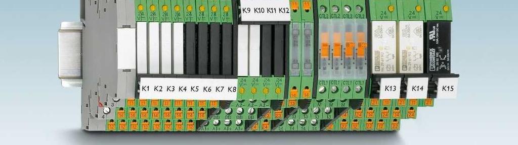
85 398 PHOENIX CONTACT


86 PHOENIX CONTACT 399
87 Notes: of housing: Polyamide PA non-reinforced, color: green. Marking systems and mounting material See Catalog 5 Separating plate PLC-ATP must be installed for voltages larger than 250 V (L1, L2, L3) between identical terminal blocks in adjacent modules. Potential bridging is then carried out with FBST 8-PLC... or FBST If the specified maximum values for multi-layer contact relays are exceeded, the gold plating is destroyed. The maximum values of the power contact relay are then valid. This can result in a shorter service life than with a pure power contact. For diagrams of operating voltage ranges, see page 423 Note: for marking material (ZB 6), see CLIPLINE industrial connection technology, marking material for terminals, conductors, and cables. 1) 120 and 230 V types up to 55 C 2) 230 V types up to 55 C 1 PDT with power contact Electrical interrupting rating for PLC...21 with 1-PDT relay Switching voltage [V] AC, ohmic load DC, ohmic load Electrical interrupting rating for PLC with 2-PDT relay Switching voltage [V] AC, ohmic load DC, ohmic load, contacts in series DC, ohmic load DC, L/R = 40 ms Input data Typ. input current at U N [ma] Response/release time at U N [ms] 5 / 8 5 / 8 6 / 15 5 / 8 5 / 8 6 / 15 7 / 15 Input circuit DC Yellow LED, protection against polarity reversal, freewheeling diode Input circuit AC/DC Yellow LED, bridge rectifier Output data Contact material AgSnO Max. switching voltage 250 V AC/DC Min. switching voltage 5 V (at 100 ma) Limiting continuous current 6 A Max. inrush current on request Min. switching current 10 ma (at 12 V) General data Test voltage input/output 4 kv AC (50 Hz, 1 min.) Ambient temperature (operation) -40 C C 1 ) Mechanical service life 2 x 10 7 cycles Standards/regulations IEC 60664, EN 50178, IEC Connection data solid / stranded / AWG mm² / mm² / Dimensions W / H / D 6.2 mm / 80 mm / 94 mm EMC note Class A product, see page 625 Description Input voltage U N PLC-INTERFACE, with screw connection 12 V DC PLC-RSC- 12DC/ V DC PLC-RSC- 24DC/ V AC/DC PLC-RSC- 24UC/ V DC PLC-RSC- 48DC/ V DC PLC-RSC- 60DC/ V AC (110 V DC) PLC-RSC-120UC/ V AC (220 V DC) PLC-RSC-230UC/ PLC-INTERFACE, with push-in connection 12 V DC PLC-RPT- 12DC/ V DC PLC-RPT- 24DC/ V AC/DC PLC-RPT- 24UC/ V DC PLC-RPT- 48DC/ V DC PLC-RPT- 60DC/ V AC (110 V DC) PLC-RPT-120UC/ V AC (220 V DC) PLC-RPT-230UC/ PHOENIX CONTACT
88 1 PDT with multi-layer gold contact 2 PDT with power contact 2 PDT with multi-layer gold contact / 8 5 / 8 6 / 15 5 / 8 5 / 8 6 / 15 7 / 15 8 / 10 8 / 10 8 / 10 8 / 10 8 / 10 7 / 10 7 / 10 8 / 10 8 / 10 8 / 10 8 / 10 8 / 10 7 / 10 7 / 10 Yellow LED, protection against polarity reversal, freewheeling diode Yellow LED, protection against polarity reversal, freewheeling diode Yellow LED, protection against polarity reversal, freewheeling diode Yellow LED, bridge rectifier Yellow LED, bridge rectifier Yellow LED, bridge rectifier AgSnO, hard gold-plated AgNi AgNi, hard gold-plated 30 V AC / 36 V DC 250 V AC/DC 30 V AC / 36 V DC 100 mv (at 10 ma) 5 V AC/DC (at 10 ma) 100 mv (at 10 ma) 50 ma 6 A 50 ma 50 ma 15 A (300 ms) 50 ma 1 ma (at 24 V) 10 ma (at 5 V) 1 ma (at 24 V) 4 kv AC (50 Hz, 1 min.) 4 kv AC (50 Hz, 1 min.) 4 kv AC (50 Hz, 1 min.) -40 C C 1 ) -40 C C 2 ) -40 C C 2 ) 2 x 10 7 cycles 3 x 10 7 cycles 3 x 10 7 cycles IEC 60664, EN 50178, IEC IEC 60664, EN 50178, IEC IEC 60664, EN 50178, IEC mm² / mm² / mm² / mm² / mm² / mm² / mm / 80 mm / 94 mm 14 mm / 80 mm / 94 mm 14 mm / 80 mm / 94 mm Class A product, see page 625 Class A product, see page 625 Class A product, see page 625 PLC-RSC- 12DC/21AU PLC-RSC- 12DC/ PLC-RSC- 12DC/21-21AU PLC-RSC- 24DC/21AU PLC-RSC- 24DC/ PLC-RSC- 24DC/21-21AU PLC-RSC- 24UC/21AU PLC-RSC- 24UC/ PLC-RSC- 24UC/21-21AU PLC-RSC- 48DC/21AU PLC-RSC- 48DC/ PLC-RSC- 48DC/21-21AU PLC-RSC- 60DC/21AU PLC-RSC- 60DC/ PLC-RSC- 60DC/21-21AU PLC-RSC-120UC/21AU PLC-RSC-120UC/ PLC-RSC-120UC/21-21AU PLC-RSC-230UC/21AU PLC-RSC-230UC/ PLC-RSC-230UC/21-21AU PLC-RPT- 12DC/21AU PLC-RPT- 12DC/ PLC-RPT- 12DC/21-21AU PLC-RPT- 24DC/21AU PLC-RPT- 24DC/ PLC-RPT- 24DC/21-21AU PLC-RPT- 24UC/21AU PLC-RPT- 24UC/ PLC-RPT- 24UC/21-21AU PLC-RPT- 48DC/21AU PLC-RPT- 48DC/ PLC-RPT- 48DC/21-21AU PLC-RPT- 60DC/21AU PLC-RPT- 60DC/ PLC-RPT- 60DC/21-21AU PLC-RPT-120UC/21AU PLC-RPT-120UC/ PLC-RPT-120UC/21-21AU PLC-RPT-230UC/21AU PLC-RPT-230UC/ PLC-RPT-230UC/21-21AU PHOENIX CONTACT 401
89 Notes: of housing: Polyamide PA non-reinforced, color: green. Marking systems and mounting material See Catalog 5 Separating plate PLC-ATP must be installed for voltages larger than 250 V (L1, L2, L3) between identical terminal blocks in adjacent modules. Potential bridging is then carried out with FBST 8-PLC... or FBST For derating curves see page 425 Max. DC voltage output of 100 ma Input data Permissible range (with reference to U N ) Switching level (with reference to U N ) 1 signal ("H") signal ("L") Typ. input current at U N [ma] Typ. switch-on time at U N [ms] Typ. shutdown time at U N [ms] Transmission frequency f limit [Hz] Input circuit DC Yellow LED, protection against polarity reversal, freewheeling diode Input circuit AC/DC Yellow LED, bridge rectifier Output data Max. switching voltage 48 V DC Min. switching voltage 3 V DC Max. inrush current - Min. / max. switching current - / 100 ma Output protection Protection against polarity reversal, surge protection Voltage drop at max. limiting continuous current 1 V Leakage current in off state - Max. load value - General data Test voltage input/output 2.5 kv (50 Hz, 1 min.) Ambient temperature (operation) -25 C C Standards/regulations IEC 60664, EN 50178, IEC Pollution degree / surge voltage category 2 / III Connection data solid / stranded / AWG mm² / mm² / Dimensions W / H / D 6.2 mm / 80 mm / 94 mm EMC note Class A product, see page 625 Description Input voltage U N PLC-INTERFACE, with screw connection 24 V DC PLC-OSC- 24DC/ 48DC/ V DC PLC-OSC- 48DC/ 48DC/ V DC PLC-OSC- 60DC/ 48DC/ V DC PLC-OSC-125DC/ 48DC/ V AC (110 V DC) PLC-OSC-120UC/ 48DC/ V AC (220 V DC) PLC-OSC-230UC/ 48DC/ PLC-INTERFACE, with push-in connection 24 V DC PLC-OPT- 24DC/ 48DC/ V DC PLC-OPT- 48DC/ 48DC/ V DC PLC-OPT- 60DC/ 48DC/ V AC (110 V DC) PLC-OPT-120UC/ 48DC/ V AC (220 V DC) PLC-OPT-230UC/ 48DC/ PHOENIX CONTACT
90 Max. DC voltage output of 3 A Max. AC voltage output of 750 ma Yellow LED, protection against polarity reversal, freewheeling diode Yellow LED, protection against polarity reversal, freewheeling diode Yellow LED, bridge rectifier Yellow LED, bridge rectifier 33 V DC 253 V AC 3 V DC 24 V AC 15 A (10 ms) 30 A (10 ms) - / 3 A (see derating curve) 10 ma / 0.75 A (see derating curve) Protection against polarity reversal, surge protection RCV circuit 200 mv < 1 V - < 1 ma (in off state) A 2 s 2.5 kv (50 Hz, 1 min.) 2.5 kv (50 Hz, 1 min.) -25 C C -25 C C IEC 60664, EN 50178, IEC IEC 60664, EN 50178, IEC / III 2 / III mm² / mm² / mm² / mm² / mm / 80 mm / 94 mm 6.2 mm / 80 mm / 94 mm Class A product, see page 625 Class A product, see page 625 PLC-OSC- 24DC/ 24DC/ PLC-OSC- 24DC/230AC/ PLC-OSC- 48DC/ 24DC/ PLC-OSC- 48DC/230AC/ PLC-OSC- 60DC/ 24DC/ PLC-OSC- 60DC/230AC/ PLC-OSC-125DC/ 24DC/ PLC-OSC-125DC/230AC/ PLC-OSC-120UC/ 24DC/ PLC-OSC-120UC/230AC/ PLC-OSC-230UC/ 24DC/ PLC-OSC-230UC/230AC/ PLC-OPT- 24DC/ 24DC/ PLC-OPT- 24DC/230AC/ PLC-OPT- 48DC/ 24DC/ PLC-OPT- 48DC/230AC/ PLC-OPT- 60DC/ 24DC/ PLC-OPT- 60DC/230AC/ PLC-OPT-120UC/ 24DC/ PLC-OPT-120UC/230AC/ PLC-OPT-230UC/ 24DC/ PLC-OPT-230UC/230AC/ PHOENIX CONTACT 403
91 Notes: of housing: Polyamide PA non-reinforced, color: green. Marking systems and mounting material See Catalog 5 Separating plate PLC-ATP must be installed for voltages larger than 250 V (L1, L2, L3) between identical terminal blocks in adjacent modules. Potential bridging is then carried out with FBST 8-PLC... or FBST For diagrams of operating voltage ranges, see page 423 For derating curves see page N/O contact with power contact Input data Permissible range (with reference to U N ) See diagram Electrical interrupting rating for PLC...24DC/1/ACT with 1-N/O relay Switching voltage [V] AC, ohmic load DC, ohmic load Electrical interrupting rating for PLC...24DC/1-1/ACT with 2-N/O relay Switching level (with reference to U N ) 1 signal ("H") 0 signal ("L") Typ. input current at U N [ma] 9 Typ. response time/switch-on time at U N [ms] 5 Typ. release time/shutdown time at U n [ms] 8 Transmission frequency f limit [Hz] Input circuit DC Yellow LED, protection against polarity reversal, freewheeling diode Output data Contact material AgSnO Max. switching voltage 250 V AC/DC Min. switching voltage 5 V (at 100 ma) Limiting continuous current 6 A Max. inrush current on request Min. switching current 10 ma (at 12 V) Output protection - Voltage drop at max. limiting continuous current - Leakage current in off state - Phase angle (cos ) - Max. load value - General data Test voltage input/output 4 kv AC (50 Hz, 1 min.) Ambient temperature (operation) -40 C C Mechanical service life 2 x 10 7 cycles Standards/regulations IEC 60664, EN 50178, IEC Pollution degree / surge voltage category 3 / III Connection data solid / stranded / AWG mm² / mm² / Dimensions W / H / D 6.2 mm / 80 mm / 94 mm EMC note Class A product, see page 625 Switching voltage [V] AC, ohmic load DC, ohmic load, contacts in series DC, ohmic load DC, L/R = 40 ms 404 PHOENIX CONTACT Description PLC-INTERFACE, with screw connection PLC-INTERFACE, with push-in connection Input voltage U N 5 V DC 24 V DC PLC-RSC- 24DC/ 1/ACT V DC 24 V DC PLC-RPT- 24DC/ 1/ACT
92 2 N/O contacts with power contact Max. DC voltage output of 3 A Max. AC voltage output of 750 ma See diagram Yellow LED, protection against polarity reversal, freewheeling diode Yellow LED, protection against polarity reversal, freewheeling diode Yellow LED, protection against polarity reversal, freewheeling diode AgNi V AC/DC 33 V DC 253 V AC 5 V AC/DC 3 V DC 24 V AC 6 A 3 A (see derating curve) 0.75 A (see derating curve) 8 A 15 A (10 ms) 30 A (10 ms) 10 ma - 10 ma - Protection against polarity reversal, surge protection RCV circuit mv < 1 V - - < 1 ma (in off state) A 2 s 4 kv AC (50 Hz, 1 min.) 2.5 kv (50 Hz, 1 min.) 2.5 kv (50 Hz, 1 min.) -40 C C -25 C C -25 C C 3 x 10 7 cycles - - IEC 60664, EN 50178, IEC IEC 60664, EN 50178, IEC IEC 60664, EN 50178, IEC / III 2 / III 2 / III mm² / mm² / mm² / mm² / mm² / mm² / mm / 80 mm / 94 mm 6.2 mm / 80 mm / 94 mm 6.2 mm / 80 mm / 94 mm Class A product, see page 625 Class A product, see page 625 Class A product, see page 625 PLC-OSC- 5DC/ 24DC/ 2/ACT PLC-RSC- 24DC/ 1-1/ACT PLC-OSC- 24DC/ 24DC/ 2/ACT PLC-OSC- 24DC/230AC/ 1/ACT PLC-OPT- 5DC/ 24DC/2/ACT PLC-OPT- 24DC/ 24DC/2/ACT PHOENIX CONTACT 405
93 Notes: of housing: Polyamide PA non-reinforced, color: green. Marking systems and mounting material See Catalog 5 Separating plate PLC-ATP must be installed for voltages larger than 250 V (L1, L2, L3) between identical terminal blocks in adjacent modules. Potential bridging is then carried out with FBST 8-PLC... or FBST For derating curves see page 425 Max. DC voltage output of 5 A Max. AC voltage output of 2 A Input data Permissible range (with reference to U N ) Switching level (with reference to U N ) 1 signal ("H") signal ("L") Typ. input current at U N [ma] 9 9 Typ. switch-on time at U N [ms] Typ. shutdown time at U N [ms] Transmission frequency f limit [Hz] Input circuit DC Yellow LED, protection against polarity reversal, freewheeling diode Yellow LED, protection against polarity reversal, freewheeling diode Output data Max. / min. switching voltage 33 V DC / 3 V DC 253 V AC / 24 V AC Max. inrush current 15 A (10 ms) 30 A (10 ms) Min. / max. switching current - / 5 A (see derating curve) 25 ma / 2 A (see derating curve) Output protection Protection against polarity reversal, surge protection Surge protection Voltage drop at max. limiting continuous current 200 mv 1 V Leakage current in off state - typ. 1 ma Phase angle (cos ) Max. load value - 4 A 2 s (tp = 10 ms, at 25 C) General data Rated insulation voltage - - Rated surge voltage Basic insulation Basic insulation Ambient temperature (operation) -20 C C -20 C C Standards/regulations IEC 60664, EN 50178, IEC IEC 60664, EN 50178, IEC Pollution degree / surge voltage category 2 / III 2 / III Mounting position / mounting see derating / can be aligned without spacing see derating / can be aligned without spacing Connection data solid / stranded / AWG mm² / mm² / mm² / mm² / Dimensions W / H / D 14 mm / 80 mm / 94 mm 14 mm / 80 mm / 94 mm Description PLC-INTERFACE, with screw connection Input voltage U N 24 V DC PLC-OSC- 24DC/ 24DC/ 5/ACT PLC-OSC- 24DC/230AC/ 2/ACT PHOENIX CONTACT
94 Notes: Maximum interrupting rating diagrams, see page 426 For derating curves see page 425 Basic terminal block that can be fitted with mech. relay Basic terminal block that can be fitted with solid-state relay Input data Permissible range (with reference to U N ) Typ. input current with U N (50 /60 Hz) 15.6 ma / 8.5 ma 15 ma / 8.3 ma Typ. response time at U N 5 ms 10 ms Typ. release time at U N 30 ms 20 ms Input circuit Yellow LED, bridge rectifier Yellow LED, bridge rectifier Output data with: REL-MR-24DC/21AU REL-MR-24DC/21 OPT...48DC/... OPT...24DC/... OPT...230AC/... Contact type Single contact, 1 N/O contact Single contact, 1 N/O contact Contact material AgSnO, hard gold-plated AgSnO Max. switching voltage 30 V AC / 36 V DC 250 V AC/DC 48 V DC 33 V DC 253 V AC Min. switching voltage 100 mv (at 10 ma) 5 V (at 100 ma) 3 V DC 3 V DC 24 V AC Limiting continuous current 50 ma 6 A 100 ma 3 A (see derating curve) 0.75 A (see derating curve) Min. switching current 1 ma (at 24 V) 10 ma (at 12 V) - Output protection - - Protection Protection RCV circuit against polarity reversal, surge protection against polarity reversal, surge protection Voltage drop at limiting continuous current V 150 mv 1 V Leakage current in off state ma Max. load value I 2 x t (t = 10 ms) A 2 s (tp = 10 ms, at 25 C) General data Rated insulation voltage 250 V AC 250 V AC Rated surge voltage / insulation 6 kv / Safe isolation, increased insulation 6 kv / Safe isolation, increased insulation Ambient temperature (operation) -20 C C -20 C C Clearance and creepage distances EN 50178, IEC EN 50178, IEC Pollution degree / Surge voltage category 2 / III 2 / III Connection data solid / stranded / AWG mm² / mm² / mm² / mm² / Dimensions W / H / D 6.2 mm / 80 mm / 94 mm 6.2 mm / 80 mm / 94 mm Description Voltage U N PLC-INTERFACE, with screw connection PLC-INTERFACE, with push-in connection 24 V AC/DC PLC-BSC- 24UC/ 1/ACT PLC-BSC- 24UC/ 1/ACT V AC/DC PLC-BPT- 24UC/ 1/ACT PLC-BPT- 24UC/ 1/ACT Accessories Accessories Plug-in miniature relay with multi-layer gold contacts REL-MR- 24DC/21AU with power contacts REL-MR- 24DC/ Plug-in solid-state relay Solid-state input relay OPT-24DC/ 48DC/ Solid-state power relay OPT-24DC/ 24DC/ Solid-state power relay OPT-24DC/230AC/ PHOENIX CONTACT 407
95 Notes: of housing: Polyamide PA non-reinforced, color: green. Marking systems and mounting material See Catalog 5 Separating plate PLC-ATP must be installed for voltages larger than 250 V (L1, L2, L3) between identical terminal blocks in adjacent modules. Potential bridging is then carried out with FBST 8-PLC... or FBST If the specified maximum values for multi-layer contact relays are exceeded, the gold plating is destroyed. The maximum values of the power contact relay are then valid. This can result in a shorter service life than with a pure power contact. For diagrams of operating voltage ranges, see page 423 1) 120 and 230 V types up to 55 C Relay module 1 N/O contact Input data Permissible range (with reference to U N ) See diagram Switching level (with reference to U N ) 1 signal ("H") 0 signal ("L") Typ. input current at U N [ma] Typ. response time/switch-on time at U N [ms] Typ. release time/shutdown time at U n [ms] Transmission frequency f limit [Hz] Input circuit DC Yellow LED, protection against polarity reversal, freewheeling diode Input circuit AC/DC Yellow LED, bridge rectifier Output data Contact material AgSnO, hard gold-plated Max. switching voltage 30 V AC / 36 V DC Min. switching voltage 100 mv (at 10 ma) Limiting continuous current 50 ma Max. inrush current 50 ma Min. switching current 1 ma (at 24 V) Output protection - Voltage drop at max. limiting continuous current - General data Test voltage input/output 4 kv AC (50 Hz, 1 min.) Ambient temperature (operation) -40 C C 1 ) Mechanical service life 2 x 10 7 cycles Standards/regulations IEC 60664, EN 50178, IEC Pollution degree / surge voltage category 3 / III Connection data solid / stranded / AWG mm² / mm² / Dimensions W / H / D 6.2 mm / 80 mm / 94 mm EMC note Class A product, see page 625 Description Input voltage U N PLC-INTERFACE, with screw connection 24 V DC PLC-RSC- 24DC/ 1AU/SEN V AC (110 V DC) PLC-RSC-120UC/ 1AU/SEN V AC (220 V DC) PLC-RSC-230UC/ 1AU/SEN PLC-INTERFACE, with push-in connection 24 V DC PLC-RPT- 24DC/ 1AU/SEN V AC (110 V DC) PLC-RPT-120UC/ 1AU/SEN V AC (220 V DC) PLC-RPT-230UC/ 1AU/SEN PHOENIX CONTACT
96 Max. DC voltage output of 100 ma Yellow LED, protection against polarity reversal, freewheeling diode Yellow LED, bridge rectifier - 48 V DC 3 V DC 100 ma - - Protection against polarity reversal, surge protection 1 V 2.5 kv (50 Hz, 1 min.) -25 C C - IEC 60664, EN 50178, IEC / III mm² / mm² / mm / 80 mm / 94 mm Class A product, see page 625 PLC-OSC- 24DC/ 48DC/100/SEN PLC-OSC-120UC/ 48DC/100/SEN PLC-OSC-230UC/ 48DC/100/SEN PLC-OPT- 24DC/ 48DC/100/SEN PLC-OPT-120UC/ 48DC/100/SEN PLC-OPT-230UC/ 48DC/100/SEN PHOENIX CONTACT 409
97 Notes: of housing: Polyamide PA non-reinforced, color: green. Marking systems and mounting material See Catalog 5 Separating plate PLC-ATP must be installed for voltages larger than 250 V (L1, L2, L3) between identical terminal blocks in adjacent modules. Potential bridging is then carried out with FBST 8-PLC... or FBST For diagrams of operating voltage ranges, see page N/O contact of up to 130 A peak Basic behavior of capacitive loads: - Very high input current - Voltage increases with an e-function Input data Typ. input current at U N [ma] 18 Response/release time at U N [ms] 8 / 10 Input circuit DC Yellow LED, protection against polarity reversal, freewheeling diode Output data Contact material AgSnO Max. switching voltage 250 V AC/DC Min. switching voltage 12 V AC/DC (at 100 ma) Max. inrush current 80 A (for 20 ms) / 130 A (peak, at capacitive load, 230 V AC, 24 F) General data Test voltage input/output 4 kv AC (50 Hz, 1 min.) Ambient temperature (operation) -40 C C Mechanical service life 3 x 10 7 cycles Standards/regulations IEC 60664, EN 50178, IEC Connection data solid / stranded / AWG mm² / mm² / Dimensions W / H / D 14 mm / 80 mm / 94 mm EMC note Class A product, see page 625 Description PLC-INTERFACE, with screw connection PLC-INTERFACE, with push-in connection Input voltage U N 24 V DC PLC-RSC- 24DC/ 1IC/ACT V DC PLC-RPT- 24DC/ 1IC/ACT Maximum interrupting rating Switching voltage [V] AC, ohmic load DC, ohmic load DC, L/R = 40 ms 410 PHOENIX CONTACT
98 Notes: of housing: Polyamide PA non-reinforced, color: green. Marking systems and mounting material See Catalog 5 Separating plate PLC-ATP must be installed for voltages larger than 250 V (L1, L2, L3) between identical terminal blocks in adjacent modules. Potential bridging is then carried out with FBST 8-PLC... or FBST For diagrams of operating voltage ranges, see page ) 230 V types up to 55 C 1 PDT up to 10 A Input data Typ. input current at U N [ma] Response/release time at U N [ms] 8 / 10 8 / 10 8 / 10 8 / 10 8 / 10 7 / 10 7 / 10 Input circuit DC Yellow LED, protection against polarity reversal, freewheeling diode Input circuit AC/DC Yellow LED, bridge rectifier Output data Contact material AgNi Max. switching voltage 250 V AC/DC Min. switching voltage 12 V AC/DC Limiting continuous current 10 A Max. inrush current 30 A (300 ms) Min. switching current 100 ma General data Test voltage input/output 4 kv AC (50 Hz, 1 min.) Ambient temperature (operation) -40 C C 1 ) Mechanical service life 3 x 10 7 cycles Standards/regulations IEC 60664, EN 50178, IEC Connection data solid / stranded / AWG mm² / mm² / Dimensions W / H / D 14 mm / 80 mm / 94 mm EMC note Class A product, see page 625 Max. interrupting rating Description Input voltage U N PLC-INTERFACE, with screw connection 12 V DC PLC-RSC- 12DC/21HC V DC PLC-RSC- 24DC/21HC V AC/DC PLC-RSC- 24UC/21HC V DC PLC-RSC- 48DC/21HC V DC PLC-RSC- 60DC/21HC V AC (110 V DC) PLC-RSC-120UC/21HC V AC (220 V DC) PLC-RSC-230UC/21HC PLC-INTERFACE, with push-in connection 12 V DC PLC-RPT- 12DC/21HC V DC PLC-RPT- 24DC/21HC V AC/DC PLC-RPT- 24UC/21HC V DC PLC-RPT- 48DC/21HC V DC PLC-RPT- 60DC/21HC V AC (110 V DC) PLC-RPT-120UC/21HC V AC (220 V DC) PLC-RPT-230UC/21HC PHOENIX CONTACT 411
99 Notes: of housing: Polyamide PA non-reinforced, color: green. Marking systems and mounting material See Catalog 5 Separating plate PLC-ATP must be installed for voltages larger than 250 V (L1, L2, L3) between identical terminal blocks in adjacent modules. Potential bridging is then carried out with FBST 8-PLC... or FBST Ex: 2 PDT with power contact 1 PDT with power contact Ex: Input data Permissible range (with reference to U N ) See diagram See diagram Switching level (with reference to U N ) 1 signal ("H") 0 signal ("L") Typ. input current at U N [ma] Typ. response time/switch-on time at U N [ms] Typ. release time/shutdown time at U n [ms] Transmission frequency f limit [Hz] Input circuit DC Yellow LED, protection against polarity reversal, surge protection Yellow LED, protection against polarity reversal, freewheeling diode Input circuit AC/DC Yellow LED, bridge rectifier Output data Contact material AgNi AgSnO Max. switching voltage 250 V AC/DC 250 V AC/DC Min. switching voltage 5 V AC/DC (at 10 ma) 5 V (at 100 ma) Limiting continuous current 6 A 6 A Max. inrush current 15 A (300 ms) on request Min. switching current 10 ma (at 5 V) 10 ma (at 12 V) Output protection - - Voltage drop at max. limiting continuous current - - General data Test voltage input/output 4 kv (50 Hz, 1 min.) 4 kv AC (50 Hz, 1 min.) Ambient temperature (operation) -20 C C (UL) -20 C C Mechanical service life 3 x 10 7 cycles 2 x 10 7 cycles Standards/regulations IEC 60664, EN 50178, IEC 62103, EN , EN IEC 60664, EN 50178, IEC 62103, EN , EN Pollution degree / surge voltage category 2 / III 3 / III Connection data solid / stranded / AWG mm² / mm² / mm² / mm² / Dimensions W / H / D 14 mm / 80 mm / 94 mm 6.2 mm / 80 mm / 94 mm EMC note Conformance / approvals Conformance CE-compliant CE-compliant ATEX DEMKO 03 ATEX U; II 3G Ex na nc IIC Gc DEMKO 11 ATEX U; II 3G Ex nc IIC Gc UL, USA Class I, Zone 2, AEx na nc IIC T6 Class I, Zone 2, AEx na nc IIC T6 UL, USA / Canada Class I, Div. 2, Groups A, B, C, D Class I, Div. 2, Groups A, B, C, D UL, Canada Class I, Zone 2, Ex na nc IIC Gc T6 X Class I, Zone 2, Ex na nc IIC Gc T6 X Description Input voltage U N PLC-INTERFACE, with screw connection 12 V DC 24 V DC PLC-RSC- 24DC/21-21ATEX PLC-RSC- 24DC/21 ATEX V AC (110 V DC) PLC-RSC-120UC/21 ATEX V AC PLC-INTERFACE, with spring-cage connection 12 V DC 120 V AC (110 V DC) 412 PHOENIX CONTACT
100 1 PDT with power contact Max. DC voltage output of 3 A Max. DC voltage output of 100 ma Ex: Ex: See diagram Yellow LED, protection against polarity reversal, protection against Yellow LED, protection against polarity reversal, freewheeling diode Yellow LED, protection against polarity reversal, freewheeling diode polarity reversal Yellow LED, bridge rectifier Yellow LED, bridge rectifier Yellow LED, bridge rectifier AgSnO V AC/DC 33 V DC 48 V DC 12 V AC/DC 3 V DC 3 V DC 6 A 3 A 100 ma - 15 A (10 ms) - 10 ma Protection against polarity reversal, surge protection Protection against polarity reversal, surge protection mv 1 V 4 kv AC (50 Hz, 1 min.) 2.5 kv (50 Hz, 1 min.) 2.5 kv (50 Hz, 1 min.) -25 C C -20 C C -25 C C 2 x 10 7 cycles - - IEC 60664, EN 50178, IEC 62103, EN , EN IEC 60664, EN 50178, IEC IEC 60664, EN 50178, IEC / III 2 / III 2 / III mm² / mm² / mm² / mm² / mm² / mm² / mm / 80 mm / 94 mm 6.2 mm / 80 mm / 94 mm 6.2 mm / 80 mm / 94 mm Class A product, see page 625 Class A product, see page 625 Class A product, see page 625 CE-compliant CE-compliant CE-compliant Class I, Zone 2, AEx na nc IIC T6 Class I, Zone 2, AEx na nc IIC T6 Class I, Zone 2, AEx na nc IIC T6 Class I, Div. 2, Groups A, B, C, D Class I, Div. 2, Groups A, B, C, D Class I, Div. 2, Groups A, B, C, D Class I, Zone 2, Ex na nc IIC Gc T6 X Class I, Zone 2, Ex na nc IIC Gc T6 X Class I, Zone 2, Ex na nc IIC Gc T6 X PLC-RSC-12DC/21-C1D PLC-RSC-24DC/21 C1D PLC-OSC- 24DC/ 24DC/ 2 C1D PLC-OSC- 24DC/ 48DC/100 C1D PLC-RSC-120UC/21 C1D PLC-OSC-120UC/ 24DC/ 2 C1D PLC-OSC-120UC/ 48DC/100 C1D PLC-RSC-230UC/21-CID PLC-RSP-12DC/21 CID PLC-RSP-120UC/21 C1D PHOENIX CONTACT 413
101 Notes: of housing: Polyamide PA non-reinforced, color: green. Marking systems and mounting material See Catalog 5 Separating plate PLC-ATP must be installed for voltages larger than 250 V (L1, L2, L3) between identical terminal blocks in adjacent modules. Potential bridging is then carried out with FBST 8-PLC... or FBST For diagrams of operating voltage ranges, see page 423 Maximum interrupting rating diagrams, see page 426 Universal design Occurrence of interference signals Scenario 1: controller - AC output card Input data Nominal input voltage U N 120 V AC 230 V AC Permissible range (with reference to U N ) Typ. release voltage (with relay) 50 V AC 80 V AC Typ. input current with U N (50 /60 Hz) 7 ma / 8 ma 8.8 ma / 10 ma Typ. response time at U N 7 ms 7 ms Typ. release time at U N 20 ms 20 ms Input circuit Yellow LED, bridge rectifier, filter Output data with: REL-MR-60DC/21 REL-MR-60DC/21AU Contact type Single contact, 1-PDT Single contact, 1-PDT Contact material AgSnO AgSnO, hard gold-plated Max. switching voltage 250 V AC/DC 30 V AC / 36 V DC Min. switching voltage 5 V (at 100 ma) 100 mv (at 10 ma) Limiting continuous current 6 A 50 ma Max. inrush current on request 50 ma Min. switching current 10 ma (at 12 V) 1 ma (at 24 V) General data Test voltage input/output 4 kv (50 Hz, 1 min.) Ambient temperature (operation) -20 C C Mechanical service life 2 x 10 7 cycles Standards/regulations IEC 60664, EN 50178, IEC Pollution degree / Surge voltage category 3 / III Connection data solid / stranded / AWG mm² / mm² / Dimensions W / H / D 6.2 mm / 80 mm / 94 mm EMC note Class A product, see page 625 Description Voltage U N PLC-INTERFACE basic terminal block, for plug-in miniature relays or solid-state relays With screw connection 120 V AC PLC-BSC-120UC/21/SO With screw connection 230 V AC PLC-BSC-230UC/21/SO With push-in connection 120 V AC PLC-BPT-120UC/21/SO With push-in connection 230 V AC PLC-BPT-230UC/21/SO Accessories Plug-in miniature relay with gold contact REL-MR- 60DC/21AU with power contact REL-MR- 60DC/ PHOENIX CONTACT Occurrence of interference signals Scenario 2: long signal cables
102 Sensor design 2 PDT universal design 1 PDT for high continuous currents 120 V AC 230 V AC 120 V AC 230 V AC 120 V AC 230 V AC V AC 80 V AC 16 V AC 70 V AC 16 V AC 70 V AC 7 ma / 8 ma 8.8 ma / 10 ma 6 ma / 7 ma 8.5 ma / 10 ma 6 ma / 7 ma 8.5 ma / 10 ma 7 ms 7 ms 7 ms 7 ms 7 ms 7 ms 20 ms 20 ms 10 ms 10 ms 20 ms 20 ms Yellow LED, bridge rectifier, filter Yellow LED, bridge rectifier, filter Yellow LED, bridge rectifier, filter REL-MR-60DC/21 REL-MR-60DC/21AU REL-MR-110DC/21-21 REL-MR-110DC/21-21AU REL-MR-110DC/21HC Single contact, 1 N/O contact Single contact, 1 N/O contact Single contact, 2-PDT Single contact, 2-PDT Single contact, 1-PDT AgSnO AgSnO, hard gold-plated AgNi AgNi, + 5 µm Au AgNi 250 V AC/DC 30 V AC / 36 V DC 250 V AC/DC 30 V AC / 36 V DC 250 V AC/DC 5 V (at 100 ma) 100 mv (at 10 ma) 5 V AC/DC 100 mv 12 V AC/DC 6 A 50 ma 6 A 50 ma 10 A on request 50 ma 15 A (300 ms) 50 ma 30 A (300 ms) 10 ma (at 12 V) 1 ma (at 24 V) 10 ma 1 ma 100 ma 4 kv (50 Hz, 1 min.) 4 kv (50 Hz, 1 min.) 4 kv (50 Hz, 1 min.) -20 C C -20 C C -20 C C 2 x 10 7 cycles 3 x 10 7 cycles 3 x 10 7 cycles IEC 60664, EN 50178, IEC IEC 60664, EN 50178, IEC IEC 60664, EN 50178, IEC / III 3 / III 3 / III mm² / mm² / mm² / mm² / mm² / mm² / mm / 80 mm / 94 mm 14 mm / 80 mm / 94 mm 14 mm / 80 mm / 94 mm Class A product, see page 625 Class A product, see page 625 Class A product, see page 625 PLC-BSC-120UC/ 1/SEN/SO PLC-BSC-120UC/21-21/SO PLC-BSC-120UC/21HC/SO PLC-BSC-230UC/ 1/SEN/SO PLC-BSC-230UC/21-21/SO PLC-BSC-230UC/21HC/SO PLC-BPT-120UC/ 1/SEN/SO PLC-BPT-230UC/ 1/SEN/SO Accessories Accessories Accessories REL-MR- 60DC/21AU REL-MR-110DC/21-21AU REL-MR- 60DC/ REL-MR-110DC/ REL-MR-110DC/21HC PHOENIX CONTACT 415
103 Notes: of housing: Polyamide PA non-reinforced, color: green. Marking systems and mounting material See Catalog 5 Separating plate PLC-ATP must be installed for voltages larger than 250 V (L1, L2, L3) between identical terminal blocks in adjacent modules. Potential bridging is then carried out with FBST 8-PLC... or FBST For derating curves see page 425 Universal design Input data Nominal input voltage U N 120 V AC 230 V AC Permissible range (with reference to U N ) Switching level (with optocoupler) 0 signal ("L") Typ. input current with U N (50 /60 Hz) 7 ma / 8 ma 8.8 ma / 10 ma Typ. response time/switch-on time at U N 6 ms 6 ms Typ. shutdown time at U N 10 ms 10 ms Input circuit Yellow LED, bridge rectifier, filter Output data with: OPT...48DC/... OPT...24DC/... OPT...230AC/... Max. switching voltage 48 V DC 30 V DC 253 V AC Min. switching voltage 3 V DC 3 V DC 24 V AC Limiting continuous current 100 ma 3 A 0.75 A Max. inrush current 15 A (10 ms) 30 A (10 ms) Output protection Protection against polarity reversal, surge protection Protection against polarity reversal, surge protection RCV circuit Voltage drop at limiting continuous current < 1 V DC < 200 mv < 1 V AC Leakage current in off state - - < 1 ma Max. phase shift (inductive load) Max. load value I 2 x t (t = 10 ms) A 2 s General data Test voltage input/output 2.5 kv (50 Hz, 1 min.) Ambient temperature (operation) -20 C C Standards/regulations IEC 60664, EN 50178, IEC Pollution degree / Surge voltage category 2 / III Connection data solid / stranded / AWG mm² / mm² / Dimensions W / H / D 6.2 mm / 80 mm / 94 mm EMC note Class A product, see page 625 Description Voltage U N PLC-INTERFACE basic terminal block, for plug-in miniature relays or solid-state relays With screw connection 120 V AC PLC-BSC-120UC/21/SO With screw connection 230 V AC PLC-BSC-230UC/21/SO With push-in connection 120 V AC PLC-BPT-120UC/21/SO With push-in connection 230 V AC PLC-BPT-230UC/21/SO Accessories Plug-in solid-state relay Solid-state input relay OPT-60DC/ 48DC/ Solid-state power relay OPT-60DC/ 24DC/ Solid-state power relay OPT-60DC/230AC/ PHOENIX CONTACT
104 Sensor design 120 V AC 230 V AC ma / 8 ma 8.8 ma / 10 ma 6 ms 6 ms 10 ms 10 ms Yellow LED, bridge rectifier, filter OPT...48DC/... OPT...24DC/... OPT...230AC/ V DC 30 V DC 253 V AC 3 V DC 3 V DC 24 V AC 100 ma 3 A 0.75 A 15 A (10 ms) 30 A (10 ms) Protection against polarity reversal, surge protection Protection against polarity reversal, surge protection RCV circuit < 1 V < 200 mv < 1 V - - < 1 ma A 2 s 2.5 kv (50 Hz, 1 min.) -20 C C IEC 60664, EN 50178, IEC / III mm² / mm² / mm / 80 mm / 94 mm Class A product, see page 625 PLC-BSC-120UC/ 1/SEN/SO PLC-BSC-230UC/ 1/SEN/SO PLC-BPT-120UC/ 1/SEN/SO PLC-BPT-230UC/ 1/SEN/SO Accessories OPT-60DC/ 48DC/ OPT-60DC/ 24DC/ OPT-60DC/230AC/ PHOENIX CONTACT 417
105 Notes: If the specified maximum values for multi-layer contact relays are exceeded, the gold plating is destroyed. The maximum values of the power contact relay are then valid. This can result in a shorter service life than with a pure power contact. For dimensional drawings and perforations for assembly, see page 424 For diagrams of operating voltage ranges, see page PDT Input data Permissible range (with reference to U N ) see diagram Typ. input current at U N [ma] Typ. response time at U N [ms] Typ. release time at U N [ms] Output data Contact type 1 PDT 1 PDT Contact material AgSnO AgSnO, hard gold-plated Max. switching voltage 250 V AC/DC 30 V AC / 36 V DC Min. switching voltage 5 V (at 100 ma) 100 mv (at 10 ma) Limiting continuous current 6 A 50 ma Max. inrush current on request on request Min. switching current 10 ma (at 12 V) 1 ma (at 24 V) Max. interrupting rating, ohmic load 24 V DC 140 W 1.2 W 48 V DC 20 W - 60 V DC 18 W V DC 23 W V DC 40 W V AC 1500 VA - General data Test voltage (winding/contact) 4 kv AC (50 Hz, 1 min.) Ambient temperature (operation) -40 C C Nominal operating mode 100% operating factor Mechanical service life 2 x 10 7 cycles Standards/regulations IEC 60664, EN 50178, IEC Mounting position / mounting any / can be aligned without spacing Dimensions W / H / D 5 mm / 28 mm / 15 mm Description Input voltage U N Plug-in miniature power relay with power contact 4.5 V DC REL-MR- 4,5DC/ with power contacts 12 V DC REL-MR- 12DC/ with power contact 18 V DC REL-MR- 18DC/ with power contacts 24 V DC REL-MR- 24DC/ with power contact 60 V DC REL-MR- 60DC/ with power contact 110 V DC Plug-in miniature power relay with gold contact 4.5 V DC REL-MR 4,5DC/21AU with multi-layer gold contacts 12 V DC REL-MR- 12DC/21AU with gold contact 18 V DC REL-MR- 18DC/21AU with multi-layer gold contacts 24 V DC REL-MR- 24DC/21AU with gold contact 60 V DC REL-MR- 60DC/21AU with gold contact 110 V DC 418 PHOENIX CONTACT
106 2 PDT 1 N/O contact, for high inrush currents 1 PDT for high continuous currents see diagram see diagram see diagram PDT 2 PDT 1 N/O contact 1 PDT AgNi AgNi, hard gold-plated AgSnO AgNi 250 V AC/DC 30 V AC / 36 V DC 250 V AC/DC 250 V AC/DC 5 V (at 10 ma) 100 mv (at 10 ma) 12 V (at 100 ma) 12 V (at 10 ma) 8 A 50 ma 16 A 16 A 25 A (20 ms) 50 ma 80 A (20 ms) 50 A (20 ms) 10 ma (at 5 V) 1 ma (at 24 V) 100 ma (at 12 V DC) 10 ma (at 12 V) 190 W 1.2 W 384 W 384 W 85 W - 58 W 58 W 60 W - 48 W 48 W 44 W - 50 W 50 W 60 W - 80 W 80 W 2000 VA VA 4000 VA 5 kv AC (50 Hz, 1 min.) 5 kv AC (50 Hz, 1 min.) 5 kv AC (50 Hz, 1 min.) -40 C C -40 C C -40 C C 100% operating factor 100% operating factor 100% operating factor 3 x 10 7 cycles 3 x 10 7 cycles 3 x 10 7 cycles IEC 60664, EN 50178, IEC IEC 60664, EN 50178, IEC IEC 60664, EN 50178, IEC any / can be aligned without spacing (> 70 C 2.5 mm) any / can be aligned without spacing (> 70 C 2.5 mm) any / can be aligned without spacing (> 70 C 2.5 mm) 12.7 mm / 29 mm / 15.7 mm 12.7 mm / 29 mm / 15.7 mm 12.7 mm / 29 mm / 15.7 mm REL-MR- 12DC/ REL-MR- 12DC/21HC REL-MR- 24DC/ REL-MR- 24DC/1IC REL-MR- 24DC/21HC REL-MR- 60DC/ REL-MR- 60DC/21HC REL-MR-110DC/ REL-MR-110DC/21HC REL-MR- 12DC/21-21AU REL-MR- 24DC/21-21AU REL-MR- 60DC/21-21AU REL-MR-110DC/21-21AU PHOENIX CONTACT 419
 [V DC] 2.5 16 35 2.5 16 52 0 signal (\"L\") [V DC] 0.8 10 20 0.8 10 40 Typ. input current at U N [ma] 9 7 3 4 7 3 Typ.")
107 Notes: For dimensional drawings and perforations for assembly, see page 425 Max. DC voltage output of 3 A Max. DC voltage output of 100 ma Input data Permissible range (with reference to U N ) Switching level 1 signal ("H") [V DC] signal ("L") [V DC] Typ. input current at U N [ma] Typ. switch-on time at U N [µs] Typ. shutdown time at U N [µs] Transmission frequency f limit [Hz] Output data Max. switching voltage 33 V DC 48 V DC Min. switching voltage 3 V DC 3 V DC Limiting continuous current 3 A (see derating curve) 100 ma Min. load current - - Max. inrush current 15 A (10 ms) - Leakage current in off state - - Phase angle (cos ) - - Output circuit 2-wire, floating 2-wire, floating Max. load value - - Output protection Protection against polarity reversal, surge protection Protection against polarity reversal, surge protection Voltage drop at max. limiting continuous current 150 mv 1 V General data Rated surge voltage Basic insulation Basic insulation Test voltage input/output 2.5 kv (50 Hz, 1 min.) 2.5 kv (50 Hz, 1 min.) Ambient temperature (operation) -25 C C -25 C C Nominal operating mode 100% operating factor 100% operating factor Standards/regulations IEC 60664, EN 50178, IEC IEC 60664, EN 50178, IEC Pollution degree / surge voltage category 2 / III 2 / III Mounting position / mounting any / can be aligned without spacing any / can be aligned without spacing Dimensions W / H / D 5 mm / 28 mm / 15 mm 5 mm / 28 mm / 15 mm Description Input voltage U N Plug-in solid-state relay Solid-state power relay 5 V DC OPT- 5DC/ 24DC/ Solid-state power relay 24 V DC OPT-24DC/ 24DC/ Solid-state power relay 60 V DC OPT-60DC/ 24DC/ Plug-in solid-state relay Solid-state input relay 5 V DC OPT- 5DC/ 48DC/ Solid-state input relay 24 V DC OPT-24DC/ 48DC/ Solid-state input relay 60 V DC OPT-60DC/ 48DC/ PHOENIX CONTACT
108 Max. DC voltage output of 5 A Max. AC voltage output of 750 ma Max. AC voltage output of 2 A V DC 253 V AC 253 V AC 3 V DC 24 V AC 24 V AC 5 A (see derating curve) 0.75 A (see derating curve) 2 A (see derating curve) - 10 ma 25 ma 15 A (10 ms) 30 A (10 ms) 30 A (10 ms) - < 1 ma < 1 ma wire, floating 2-wire floating, zero voltage switch 2-wire floating, zero voltage switch A 2 s 4 A 2 s (tp = 10 ms, at 25 C) Protection against polarity reversal, surge protection RCV circuit Surge protection 200 mv < 1 V 1 V Basic insulation Basic insulation Basic insulation 2.5 kv (50 Hz, 1 min.) 2.5 kv (50 Hz, 1 min.) 2.5 kv (50 Hz, 1 min.) -25 C C -25 C C -25 C C 100% operating factor 100% operating factor 100% operating factor IEC 60664, EN 50178, IEC IEC 60664, EN 50178, IEC IEC / III 2 / III 2 / III any / can be aligned without spacing any / can be aligned without spacing any / see derating curve 12.7 mm / 29 mm / 15.7 mm 5 mm / 28 mm / 15 mm 12.7 mm / 29 mm / 15.7 mm OPT- 5DC/ 24DC/ OPT- 5DC/230AC/ OPT-24DC/ 24DC/ OPT-24DC/230AC/ OPT-24DC/230AC/ OPT-60DC/ 24DC/ OPT-60DC/230AC/ OPT-60DC/230AC/ PHOENIX CONTACT 421
109 Relay and solid-state relay options REL-MR-4,5DC/ X X X REL-MR-4,5DC/21AU X X REL-MR-12DC/ X REL-MR-12DC/21AU X REL-MR-24DC/ X X X X X X REL-MR-24DC/21AU X X X X X X REL-MR-60DC/ X X X X X X REL-MR-60DC/21AU X X X X X X REL-MR-24DC/1IC X REL-MR-18DC/ X REL-MR-18DC/21AU X REL-MR-12DC/ X REL-MR-12DC/21-21AU X REL-MR-24DC/ X X X REL-MR-24DC/21-21AU X X X REL-MR-60DC/ X REL-MR-60DC/21-21AU X REL-MR-110DC/ X X REL-MR-110DC/21-21AU X X REL-MR-12DC/21HC X REL-MR-24DC/21HC X X X REL-MR-60DC/21HC X REL-MR-110DC/21HC X X OPT-24DC/230AC/ X X X X X OPT-60DC/230AC/ X X X X X OPT-5DC/24DC/ X X X OPT-24DC/24DC/ X X X X X OPT-60DC/24DC/ X X X X X OPT-5DC/48DC/ X X X OPT-24DC/48DC/ X X X X X OPT-60DC/48DC/ X X X X X OPT-24DC/24DC/ X X X X X OPT-60DC/24DC/ X X OPT-24DC/230AC/ X X X X X OPT-60DC/230AC/ X X 422 PHOENIX CONTACT
110 PLC-R...-12DC... PLC-R...-24DC... PLC-R...-24UC... PLC-R...-48DC... PLC-R...-60DC... PLC-R UC... PLC-R DC... PLC-R UC... PLC-R...-12DC... PLC-R...-24DC... PLC-R...-24UC... PLC-R...-48DC... PLC-R...-60DC... PLC-R UC... PLC-R UC... General conditions: Direct alignment in the block, all devices 100% operating time, horizontal or vertical mounting. Curve A Maximum permitted continuous voltage U max with limiting continuous current on the contact side (see relevant technical data). Curve B Minimum permitted pick-up voltage U op after pre-excitation 1 ) (see relevant technical data). 1 ) Pre-excitation: relay has been operated in a thermally steady state at the ambient temperature T A with nominal voltage U N and limiting continuous current on the contact side (see relevant technical data) (warm coil). After being switched off for a short time, the relay must reliably pick up again at U op. The U op values for cold coils (T coil = T A = 20 C) indicated by other manufacturers yield better values, but are not practical. PHOENIX CONTACT 423
111 Permitted input voltage range for REL-MR...21 Permitted input voltage range for REL-MR , REL-MR-24DC/1IC, REL-MR...21HC General conditions: Direct alignment in the block, all devices 100% operating time, horizontal or vertical mounting. Curve A Maximum permitted continuous voltage U max with limiting continuous current on the contact side (see relevant technical data). Curve B Minimum permitted pick-up voltage U op after pre-excitation 1 ) (see relevant technical data). 1 ) Pre-excitation: relay has been operated in a thermally steady state at the ambient temperature T A with nominal voltage U N and limiting continuous current on the contact side (see relevant technical data) (warm coil). After being switched off for a short time, the relay must reliably pick up again at U op. The U op values for cold coils (T coil = T A = 20 C) indicated by other manufacturers yield better values, but are not practical. 5 mm overall width 12.7 mm overall width Perforations for assembly: view of the connections Perforations for assembly: view of the connections Pitch division: 1.25 mm and 1.27 mm Pitch division: 2.5 mm 424 PHOENIX CONTACT
112 Derating curve for OPT...DC/24DC/2 and PLC-OS.../24DC/2 solid-state relays Derating curve for OPT...DC/24DC/5 and PLC-OS.../24DC/5/ACT solid-state relays Ambient temperature range [ C] Ambient temperature range [ C] Derating curve for OPT...DC/230AC/1 and PLC-OS.../230AC/1 solid-state relays Derating curve for OPT...DC/230AC/2 and PLC-OS.../230AC/2/ACT solid-state relays Ambient temperature range [ C] Ambient temperature range [ C] Aligned with > 10 mm spacing Aligned without spacing 5 mm overall width 12.7 mm overall width PHOENIX CONTACT 425
113 Electrical interrupting rating for PLC...21 with 1 PDT relay Electrical service life for PLC-RSP...UC/21RW Switching voltage [V] AC, ohmic load DC, ohmic load Switching current [A] 250 V AC, ohmic load Electrical interrupting rating for PLC with 2 PDT relay Switching voltage [V] AC, ohmic load DC, ohmic load, contacts in series DC, ohmic load DC, L/R = 40 ms Electrical service life for PLC-RSP...UC/21-21/RW Switching current [A] 250 V AC, ohmic load (DC coils) 250 V AC, ohmic load (AC coils) Electrical interrupting rating for PLC...1IC/ACT for high inrush currents Switching voltage [V] AC, ohmic load DC, ohmic load DC, L/R = 40 ms Electrical service life for PLC-RSP...UC/21HC/RW Switching current [A] 250 V AC, ohmic load (DC coils) 250 V AC, ohmic load (AC coils) Electrical interrupting rating for PLC...21HC for high continuous currents AC, ohmic load DC, ohmic load DC, L/R = 40 ms Switching voltage [V] 426 PHOENIX CONTACT
114 Derating curve for EMG 17-OV...48DC/2 Derating curve for ST-OV 4-24DC/24DC...PRO Time diagrams for UEGM-OE/AV-24DC/24DC/100 Ambient temperature [ C] Aligned without spacing Stand-alone device 4 A type 1 A type Ambient temperature [ C] Time-current characteristic, 1 A version Scenario 1: input pulse t I < output pulse t O set Operating voltage present Output pulse t O Set Scenario 2: input pulse t I output pulse t O set : t I = t O Operating voltage present Current limitation Output pulse t O Time-current characteristic, 4 A version Set Table of adjustable output pulse lengths DIP switches 1 ) S1 S2 S3 S4 S5 S6 S7 S Current limitation Length of output pulses [ms] (when in on switch position) State diagram Operating state Not activated Switching level Input Light indicator, yellow LED Light indicator, red LED L L L Alarm contact/ CONTROL 1) If no switch is actuated, the output voltage is not defined. If the input pulse is longer than the set time, the output is switched off almost simultaneously with the input. Intermediate values can be obtained by combining several DIP switches according to the following formula: 1 T tot = t 1 t 2 t n Normal operation Overload/s hort circuit H H L H H H Open circuit L L H PHOENIX CONTACT 427
115 Notes: of housing: Polyamide PA non-reinforced, color: green. Marking systems and mounting material See Catalog 5 Two integrated relays Input data Typ. input current at U N [ma] 7 Response/release time at U N [ms] 4 / 6 Input circuit DC Yellow LED, protection against polarity reversal, freewheeling diode Output data Contact material AgNi Max. switching voltage 250 V AC/DC Min. switching voltage 24 V AC/DC Limiting continuous current 3.5 A Min. switching current 5 ma General data Test voltage input/output 3 kv AC (50 Hz, 1 min.) Test voltage output/output 3 kv AC (50 Hz, 1 min.) Ambient temperature (operation) -20 C C Mechanical service life 2 x 10 7 cycles Standards/regulations IEC 60664, EN 50178, IEC Connection data solid / stranded / AWG mm² / mm² / Dimensions W / H / D 6.2 mm / 80 mm / 86 mm EMC note Class A product, see page 625 Description PLC-INTERFACE, with screw connection PLC-INTERFACE, with push-in connection Input voltage U N 24 V DC PLC-2RSC-24DC/ V DC PLC-2RPT-24DC/ PHOENIX CONTACT
116 Application example for PLC-2RS...24DC/1 Operating voltage range Ambient temperature Interrupting rating Switching voltage [V] DC, ohmic load PHOENIX CONTACT 429
117 Notes: of housing: Polyester PBT non-reinforced, color: green. Marking systems and mounting material See Catalog 5 For the protection of input and output, inductive loads must be dampened with an effective protection circuit. Separating plate PLC-ATP is to be used in the following cases: always at the start and end of a PLC terminal strip, for voltages greater than 250 V (L1, L2, L3) between the same terminal points of neighboring modules (potential bridging then takes place with FBST 8-PLC... or FBST ) and with safe isolation between neighboring modules. Module height: PLC-...-S/H = 90 mm; PLC-...-S/L: = 86 mm PLC...H - manual operation PLC...L - operation using screwdriver Relay module with manual switch and integrated relay Application example PLC-RS...24UC/1/S... Permissible input voltage range for PLC-RS...24UC/1/S... Input data Typ. input current at U N [ma] Response/release time at U N [ms] 6 / 15 6 / 15 Input circuit AC/DC Yellow LED, bridge rectifier Output data Contact material AgSnO Max. switching voltage 250 V AC/DC Min. switching voltage 5 V (at 100 ma) Limiting continuous current 6 A Max. inrush current on request Min. switching current 10 ma (at 12 V) Feedback Operating mode Automatic floating max. 30 V AC/DC / 50 ma min. 2 V AC/DC / 1 ma General data Rated insulation voltage 250 V AC Rated surge voltage 6 kv Ambient temperature (operation) -20 C C Standards/regulations IEC 60664, EN 50178, IEC Pollution degree / surge voltage category 2 / III Connection data solid / stranded / AWG mm² / mm² / Dimensions W / H / D 6.2 mm / 80 mm / 90 mm EMC note Class A product, see page 625 Description PLC-INTERFACE, with screw connection PLC-INTERFACE, with push-in connection Input voltage U N 24 V AC/DC PLC-RSC- 24UC/ 1/S/H V AC/DC PLC-RSC- 24UC/ 1/S/L V AC/DC PLC-RPT- 24UC/ 1/S/H V AC/DC PLC-RPT- 24UC/ 1/S/L Curve A maximum continuous voltage at limiting continuous current = 6 A Curve B minimum operating voltage for pre-excitation with U N and limiting continuous current = 6 A 430 PHOENIX CONTACT
118 Notes: of housing: Polyester PBT non-reinforced, color: green. Marking systems and mounting material See Catalog 5 For the protection of input and output, inductive loads must be dampened with an effective protection circuit. Separating plate PLC-ATP is to be used in the following cases: always at the start and end of a PLC terminal strip, for voltages greater than 250 V (L1, L2, L3) between the same terminal points of neighboring modules (potential bridging then takes place with FBST 8-PLC... or FBST ) and with safe isolation between neighboring modules. Module height: PLC-...-S/H = 90 mm; PLC-...-S/L: = 86 mm PLC...H - manual operation PLC...L - operation using screwdriver Module with manual switch without relay Max. switching voltage Min. switching voltage Max. inrush current Min. switching current Cycles, max. 72 V DC 2 V DC 50 ma 1 ma 100 (at 72 V DC / 50 ma) / (at 12 V DC / 100 ma) Feedback Operating mode Automatic floating 72 V DC / 50 ma General data Rated insulation voltage 85 V AC Rated surge voltage 0.5 kv / basic insulation Ambient temperature (operation) -20 C C Standards/regulations IEC 60664, EN 50178, IEC Pollution degree / surge voltage category 2 / III Dimensions W / H / D 6.2 mm / 80 mm / 90 mm Application example PLC-S...S... Description PLC-INTERFACE, with screw connection PLC-INTERFACE, with spring-cage connection PLC-SC-S/H PLC-SC-S/L PLC-SP-S/H PLC-SP-S/L PHOENIX CONTACT 431
119 Notes: of housing: Polyester PBT non-reinforced, color: green. Marking systems and mounting material See Catalog 5 For the protection of input and output, inductive loads must be dampened with an effective protection circuit. Separating plate PLC-ATP is to be used in the following cases: always at the start and end of a PLC terminal strip, for voltages greater than 250 V (L1, L2, L3) between the same terminal points of neighboring modules (potential bridging then takes place with FBST 8-PLC... or FBST ) and with safe isolation between neighboring modules. The housings of the following modules are open on one side: - PLC-OS DC/1 - PLC-OS...-24DC/24DC/10/R Power solid-state relay with DC voltage output, max. 1 A Input data Permissible range (with reference to U N ) Switching level (with reference to U N ) 1 signal ("H") signal ("L") Typ. input current at U N [ma] Transmission frequency f limit [Hz] Alarm output Operating range - / - Output data Max. / min. switching voltage 300 V DC / 12 V DC Limiting continuous current 1 A (see derating curve) Voltage drop at max. limiting continuous current < 500 mv General data Rated insulation voltage 300 V Rated surge voltage 4 kv / basic insulation Ambient temperature (operation) -25 C C Standards/regulations IEC 60664, EN 50178, IEC Connection data solid / stranded / AWG mm² / mm² / Dimensions W / H / D 6.2 mm / 80 mm / 86 mm EMC note Class A product, see page 625 Description Input voltage U N PLC-INTERFACE, with screw connection 5 V DC PLC-OSC- 5DC/300DC/ V DC PLC-OSC- 12DC/300DC/ V DC PLC-OSC- 24DC/300DC/ V DC V DC 60 V DC PLC-OSC- 60DC/300DC/ V DC PLC-OSC-110DC/300DC/ V DC PLC-OSC-220DC/300DC/ V AC PLC-OSC-120AC/300DC/ V AC PLC-OSC-230AC/300DC/ PLC-INTERFACE, with push-in connection 5 V DC PLC-OPT- 5DC/300DC/ V DC PLC-OPT- 12DC/300DC/ V DC PLC-OPT- 24DC/300DC/ V DC V DC 60 V DC PLC-OPT- 60DC/300DC/ V DC PLC-OPT-110DC/300DC/ V DC PLC-OPT-220DC/300DC/ V AC PLC-OPT-120AC/300DC/ V AC PLC-OPT-230AC/300DC/ PHOENIX CONTACT
120 Derating curve for PLC...300DC/1 Ambient temperature [ C] For input voltages 220 V DC and 230 V AC Power solid-state relay with short-circuit-proof DC voltage output, max. 10 A, with feedback Input solid-state relay with DC voltage output, max. 500 ma, with electronic PDT Derating curve for PLC-...24DC/24DC/10/R Ambient temperature [ C] Derating curve for PLC...24DC/48DC/500/W V DC V DC (High active) / 100 ma - / - 33 V DC / 5 V DC 48 V DC / 3 V DC 10 A (see derating curve) 500 ma (see derating curve) 50 mv < 1.2 V 300 V 300 V 4 kv / basic insulation 4 kv / basic insulation -25 C C -25 C C IEC 60664, EN 50178, IEC IEC 60664, EN 50178, IEC mm² / mm² / mm² / mm² / mm / 80 mm / 86 mm 6.2 mm / 80 mm / 86 mm Class A product, see page 625 Class A product, see page 625 Ambient temperature [ C] PLC-OSC- 24DC/ 24DC/ 10/R PLC-OSC- 24DC/ 48DC/500/W PLC-OPT- 24DC/ 24DC/10/R PLC-OPT- 24DC/ 48DC/500/W PHOENIX CONTACT 433
121 Solid-state power relay with AC voltage output, max. 2.4 A Input data Rated actuating voltage range with reference to U C Rated actuating current I C [ma] 8 Switching level (with reference to U C ) 1 signal ("H") > signal ("L") < 0.4 Typ. switch-on time at U N [ms] 10 Typ. shutdown time at U N [ms] 10 Transmission frequency f limit [Hz] 10 Input circuit DC Yellow LED, protection against polarity reversal, surge protection Output data Max. switching voltage 253 V AC Min. switching voltage 24 V AC Max. inrush current 250 A (20 ms) Min. / max. switching current 10 ma / 2.4 A (see to derating) Output protection RCV circuit Voltage drop at max. limiting continuous current < 1 V Leakage current in off state < 1 ma Phase angle (cos ) - Max. load value 340 A 2 s (tp = 10 ms, at 25 C) General data Rated insulation voltage 260 V AC Rated surge voltage 4 kv Insulation Basic insulation Ambient temperature (operation) -25 C C Standards/regulations DIN EN Pollution degree / surge voltage category 2 / III Connection data solid / stranded / AWG mm² / mm² / Dimensions W / H / D 6.2 mm / 80 mm / 86 mm EMC note Class A product, see page 625 Load current as a function of the ambient temperature Operating time: 100% operating factor Description PLC-INTERFACE, with screw connection PLC-INTERFACE, with push-in connection Rated actuating voltage U C 24 V DC PLC-OSC- 24DC/230AC/2.4/ACT V DC PLC-OPT- 24DC/230AC/2.4/ACT PHOENIX CONTACT
122 Hybrid solid-state relay with AC voltage output, max. 10 A Input data Rated control supply voltage U S [V DC] 24 Rated control supply voltage range with reference to U S Rated control supply current I S 14 ma (input low, output low) 19 ma (input high, output high) Rated actuation voltage U C ON [V DC] 24 Rated actuating voltage range with reference to U C Rated actuating current I C [ma] 6.8 Input circuit DC Yellow LED, protection against polarity reversal, surge protection Output data Max. switching voltage 253 V AC Min. switching voltage 24 V AC Max. inrush current - Min. / max. switching current 100 ma / 10 A (see derating curve) Output protection RCV circuit Voltage drop at max. limiting continuous current - Leakage current in off state < 1 ma Phase angle (cos ) - Max. load value 350 A 2 s (tp = 10 ms, at 25 C) General data Rated insulation voltage 260 V AC Rated surge voltage 6 kv Insulation safe isolation Ambient temperature (operation) -25 C C Standards/regulations DIN EN Pollution degree / surge voltage category 2 / III Connection data solid / stranded / AWG mm² / mm² / Dimensions W / H / D 6.2 mm / 80 mm / 86 mm Description PLC-INTERFACE, with screw connection PLC-INTERFACE, with push-in connection Rated actuating voltage U C 24 V DC PLC-HSC-24DC/230AC/ V DC PLC-HPT-24DC/230AC/ PHOENIX CONTACT 435
123 Notes: of housing: Polyamide PA non-reinforced, color: green. Marking systems and mounting material See Catalog 5 With DC voltage output Transmission frequency 100 khz Input data Permissible range (with reference to U N ) Switching level with reference to U N 1 signal ("H") > 0.8 > signal ("L") < 0.4 < 0.4 Typ. input current at U N [ma] 7 6 Typ. switch-on time at U N [µs] Typ. shutdown time at U N [µs] 2 2 Transmission frequency f limit [khz] Input protection: Yellow LED, protection against polarity reversal, surge protection Output data Operating voltage range 4 V DC V DC Limiting continuous current 50 ma Quiescent current 4.3 ma Residual voltage drop at "H" < 0.5 V Output circuit 3-conductor, ground-referenced Output protection Protection against polarity reversal, surge protection General data Test voltage input/output 2.5 kv rms (50 Hz, 1 min.) Ambient temperature (operation) -20 C C Standards/regulations DIN EN Pollution degree / surge voltage category 2 / II Connection data solid / stranded / AWG mm² / mm² / Dimensions W / H / D 6.2 mm / 80 mm / 86 mm EMC note Class A product, see page 625 Description Input solid-state relay with screw connection Input voltage U N Input solid-state relay with push-in connection 5 V DC PLC-OSC- 5DC/ 24DC/100KHZ V DC PLC-OSC- 24DC/ 24DC/100KHZ V DC PLC-OPT- 5DC/ 24DC/100KHZ V DC PLC-OPT- 24DC/24DC/100KHZ PHOENIX CONTACT
124 With DC voltage output push-pull Transmission frequency 100 khz With DC voltage output push-pull Transmission frequency 100 khz > 0.5 > 0.8 > 0.5 > 0.8 < 0.3 < 0.4 < 0.3 < Yellow LED, protection against polarity reversal, surge protection Yellow LED, protection against polarity reversal, surge protection 4 V DC V DC 14 V DC V DC 50 ma 50 ma 8.5 ma 15 ma < 1.2 V < 2.2 V 3-conductor push-pull, ground referenced 3-conductor push-pull, ground referenced Protection against polarity reversal, surge protection Protection against polarity reversal, surge protection 2.5 kv rms (50 Hz, 1 min.) 2.5 kv rms (50 Hz, 1 min.) -20 C C -20 C C DIN EN DIN EN / II 2 / II mm² / mm² / mm² / mm² / mm / 80 mm / 86 mm 6.2 mm / 80 mm / 86 mm Class A product, see page 625 Class A product, see page 625 PLC-OSC- 5DC/ 5DC/100KHZ-G PLC-OSC- 5DC/ 24DC/100KHZ-G PLC-OSC- 24DC/ 5DC/100KHZ-G PLC-OSC- 24DC/ 24DC/100KHZ-G PLC-OPT- 5DC/ 5DC/100KHZ-G PLC-OPT- 5DC/24DC/100KHZ-G PLC-OPT- 24DC/ 5DC/100KHZ-G PLC-OPT- 24DC/24DC/100KHZ-G PHOENIX CONTACT 437
125 Notes: of housing: Polyester PBT non-reinforced, color: green. Marking systems and mounting material See Catalog 5 Basic terminal block, for fitting with relay for TTL (5 V) Input data Rated control supply voltage U VN 5 V DC Rated control supply voltage range with reference to U VN Rated control supply current I VN 41 ma Rated actuating voltage U c (IN) 5 V DC (TTL) Rated actuating voltage range with reference to U C Rated actuating current I C Typ. response time at U c Typ. release time for U c Input circuit 2.5 ma 4.5 ms 3.5 ms Yellow LED, protection against polarity reversal, surge protection Output data with: REL-MR-4,5DC/21 AU REL-MR-4,5DC/21 Contact type Single contact, 1 N/O contact Single contact, 1 N/O contact Contact material AgSnO, hard gold-plated AgSnO Max. switching voltage 30 V AC / 36 V DC 250 V AC/DC Min. switching voltage 100 mv (at 10 ma) 5 V (at 100 ma) Limiting continuous current 50 ma 6 A Max. inrush current 50 ma on request Min. switching current 1 ma (at 24 V) 10 ma (at 12 V) General data Rated insulation voltage 250 V Rated surge voltage / insulation 6 kv Ambient temperature (operation) -20 C C Mechanical service life 2 x 10 7 cycles Clearance and creepage distances between the power circuits IEC 60664, EN 50178, IEC Pollution degree / Surge voltage category 2 / III Max. interrupting rating Mounting position / mounting any / can be aligned without spacing Connection data solid / stranded / AWG mm² / mm² / Dimensions W / H / D 6.2 mm / 80 mm / 94 mm EMC note Class A product, see page 625 Description PLC-INTERFACE With screw connection PLC-BSC-TTL/ With push-in connection PLC-BPT-TTL/ Accessories Plug-in miniature power relay with gold contact REL-MR 4,5DC/21AU with power contact REL-MR- 4,5DC/ PHOENIX CONTACT
126 Notes: of housing: Polyester PBT non-reinforced, color: green. Marking systems and mounting material See Catalog 5 For derating curves see page 425 Basic terminal block for fitting with solid-state relay for TTL (5 V) Input data Rated control supply voltage U VN 5 V DC Rated control supply voltage range with reference to U VN Rated control supply current I VN 11.5 ma Rated actuating voltage U c (IN) 5 V DC (TTL) Switching level 1 signal ("H") (TTL signal) > 2 V DC Switching level 0 signal ("L") (TTL signal) < 0.8 V DC Rated actuating current I C 2.5 ma Typ. response time/switch-on time at U c 35 µs Typ. shutdown time at U C 320 µs Input circuit Yellow LED, protection against polarity reversal, surge protection Output data with: OPT-5DC/48DC/100 OPT-5DC/24DC/2 Max. switching voltage 48 V DC 33 V DC Min. switching voltage 3 V DC 3 V DC Limiting continuous current 100 ma 3 A Output protection Protection against polarity reversal, surge protection Protection against polarity reversal, surge protection Voltage drop at limiting continuous current < 1 V < 200 mv General data Rated insulation voltage 250 V Rated surge voltage / insulation 6 kv / Basic insulation Ambient temperature (operation) -20 C C Clearance and creepage distances between the power circuits IEC 60664, EN 50178, IEC Pollution degree / Surge voltage category 2 / III Connection data solid / stranded / AWG mm² / mm² / Dimensions W / H / D 6.2 mm / 80 mm / 94 mm EMC note Class A product, see page 625 Description PLC-INTERFACE With screw connection PLC-BSC-TTL/ With push-in connection PLC-BPT-TTL/ Accessories Plug-in solid-state relay Solid-state input relay OPT- 5DC/ 48DC/ Solid-state power relay OPT- 5DC/ 24DC/ PHOENIX CONTACT 439
127 Notes: of housing: Polyester PBT non-reinforced, color: green. Marking systems and mounting material See Catalog 5 Input solid-state relay with TTL (5 V) output Input data Rated actuating voltage U C 24 V DC Rated actuating voltage range with reference to U C Switching level 1 signal ("H") > 0.8 Switching level 0 signal ("L") < 0.4 Rated actuating current I C 3.4 ma Typ. switch-on time for U c 35 µs Typ. shutdown time at U C 35 µs Transmission frequency f limit 1 khz Input circuit DC Yellow LED, protection against polarity reversal, surge protection Output data with: Rated control supply voltage U S 5 V DC Rated control supply voltage range with reference to U S Limiting continuous current A TTL load (Fan out = 1)/50 ma for switching mode Derating curve for PLC-OSP...24DC/3RW Ambient temperature [ C] Aligned without spacing Aligned with 20 mm spacing Derating curve for PLC-OSP...110DC/3RW Output protection Protection against polarity reversal, surge protection Voltage drop at max. limiting continuous current < 80 mv General data Rated insulation voltage 250 V DC Rated surge voltage / insulation 4 kv / basic insulation Ambient temperature (operation) -25 C C Clearance and creepage distances between the power circuits IEC 60664, EN 50178, IEC Pollution degree / surge voltage category Connection data solid / stranded / AWG mm² / mm² / Dimensions W / H / D 6.2 mm / 80 mm / 86 mm EMC note Class A product, see page / III Description PLC-INTERFACE With screw connection PLC-OSC- 24DC/TTL With push-in connection PLC-OPT- 24DC/TTL Ambient temperature [ C] 440 PHOENIX CONTACT
128 Power solid-state relay with DC voltage output, max. 3 A Power solid-state relay with DC voltage output, max. 3 A Notes: of housing: Polyester PBT non-reinforced, color: green. Marking systems and mounting material See Catalog 5 For derating curves see page 440 Input data Permissible range (with reference to U N ) Switching level (with reference to U N ) 1 signal ("H") > 0.6 > 0.6 > 0.6 > 0.6 > 0.6 > signal ("L") < 0.4 < 0.4 < 0.3 < 0.3 < 0.3 < 0.3 Typ. input current at U N [ma] Typ. switch-on time at U N [ms] Typ. shutdown time at U N [ms] Transmission frequency f limit [Hz] Input circuit DC Yellow LED, protection against polarity reversal Yellow LED, protection against polarity reversal, surge protection Output data Max. switching voltage 33 V DC 140 V DC Min. switching voltage 3 V DC 12 V DC Limiting continuous current 3 A (see derating curve) 3 A (see derating curve) Output protection Protection against polarity reversal, surge protection Protection against polarity reversal, surge protection Voltage drop at max. limiting continuous current < 200 mv < 150 mv General data Rated insulation voltage 250 V 160 V DC Rated surge voltage 4 kv / basic insulation 4 kv / basic insulation Ambient temperature (operation) -25 C C -25 C C Standards/regulations IEC 60664, EN 50178, IEC IEC 60664, EN 50178, IEC Pollution degree / surge voltage category 2 / III 2 / III Connection data solid / stranded / AWG mm² / mm² / mm² / mm² / Dimensions W / H / D 6.2 mm / 80 mm / 86 mm 6.2 mm / 80 mm / 86 mm EMC note Class A product, see page 625 Description PLC-INTERFACE, with spring-cage connection PLC-INTERFACE, with push-in connection Input voltage U N 24 V DC PLC-OSP- 24DC/ 24DC/ 3RW PLC-OSP- 24DC/110DC/ 3RW V DC PLC-OSP- 36DC/110DC/ 3RW V DC PLC-OSP- 48DC/110DC/ 3RW V DC PLC-OSP- 72DC/110DC/ 3RW V DC PLC-OSP- 96DC/110DC/ 3RW V DC PLC-OSP-110DC/ 24DC/ 3RW PLC-OSP-110DC/110DC/ 3RW V DC PLC-OPT- 24DC/ 24DC/3RW PLC-OPT- 24DC/110DC/3RW V DC PLC-OPT- 36DC/110DC/3RW V DC PLC-OPT- 48DC/110DC/3RW V DC PLC-OPT- 72DC/110DC/3RW V DC PLC-OPT- 96DC/110DC/3RW V DC PLC-OPT-110DC/ 24DC/3RW PLC-OPT-110DC/110DC/3RW PHOENIX CONTACT 441
129 Notes: of housing: Polyamide PA non-reinforced, color: green. Marking systems and mounting material See Catalog 5 Separating plate PLC-ATP must be installed for voltages larger than 250 V (L1, L2, L3) between identical terminal blocks in adjacent modules. Potential bridging is then carried out with FBST 8-PLC... or FBST If the specified maximum values for multi-layer contact relays are exceeded, the gold plating is destroyed. The maximum values of the power contact relay are then valid. This can result in a shorter service life than with a pure power contact. Basic terminal block for fitting with 1 PDT relay Permitted input voltage range for PLC-BSP-24DC/21RW (with REL-MR-18DC/21... relay) Ambient temperature [ C] Maximum continuous voltage at limiting continuous current = 3 A Minimum pick-up voltage for pre-excitation with U N and limiting continuous current = 3 A Electrical interrupting rating for PLC...21 with 1 PDT relay Switching voltage [V] AC, ohmic load DC, ohmic load Input data Nominal input voltage U N 24 V DC Permissible range (with reference to U N ) See diagram Typ. input current at U N 12 ma Typ. response time at U N 5 ms Typ. release time at U N 8 ms Input circuit Yellow LED, protection against polarity reversal, freewheeling diode Output data with: REL-MR-18DC/21 REL-MR-18DC/21AU Contact type Single contact, 1-PDT Single contact, 1-PDT Contact material AgSnO AgSnO, hard gold-plated Max. switching voltage 250 V AC/DC 30 V AC / 36 V DC Min. switching voltage 5 V (at 100 ma) 100 mv (at 10 ma) Limiting continuous current 3 A 50 ma Max. inrush current on request 50 ma Min. switching current 10 ma (at 12 V) 1 ma (at 24 V) General data Test voltage input/output 4 kv (50 Hz, 1 min.) Ambient temperature (operation) -25 C C Mechanical service life 2 x 10 7 cycles Standards/regulations IEC 60664, EN 50178, IEC Pollution degree / Surge voltage category 3 / III Connection data solid / stranded / AWG mm² / mm² / Dimensions W / H / D 6.2 mm / 80 mm / 94 mm EMC note Class A product, see page 625 Description Voltage U N PLC-INTERFACE basic terminal block, for plug-in miniature relay With push-in connection 24 V DC PLC-BPT- 24DC/21RW Accessories Plug-in miniature relay with power contact REL-MR- 18DC/ with gold contact REL-MR- 18DC/21AU PHOENIX CONTACT
130 Notes: of housing: Polyamide PA non-reinforced, color: green. Marking systems and mounting material See Catalog 5 Separating plate PLC-ATP must be installed for voltages larger than 250 V (L1, L2, L3) between identical terminal blocks in adjacent modules. Potential bridging is then carried out with FBST 8-PLC... or FBST If the specified maximum values for multi-layer contact relays are exceeded, the gold plating is destroyed. The values in parentheses then apply for further operation. This can result in a shorter service life than with a pure power contact. For 16.7 Hz input frequency with 2 PDTs Permitted input voltage range for PLC-RSP-230UC/21-21AU/RWF Input data Nominal input voltage U N 230 V AC Input nominal frequency Hz Permissible range (with reference to U N ) see diagram Typ. input current at U N - Typ. response time at U N 20 ms Typ. release time at U N 60 ms Input circuit Yellow LED, bridge rectifier Output data Contact type 2 PDT Contact material AgNi, hard gold-plated Max. switching voltage 30 V AC / 36 V DC ( 250 V AC/DC ) Min. switching voltage 100 mv ( 5 V AC/DC ) Limiting continuous current 50 ma ( 6 A ) Max. inrush current 50 ma ( 8 A ) Min. switching current 1 ma ( 10 ma ) General data Test voltage input/output 6 kv Ambient temperature (operation) -25 C C Mechanical service life Approx. 3 x 10 7 cycles Standards/regulations IEC 60664, EN 50178, IEC Pollution degree / Surge voltage category 2 / III Connection data solid / stranded / AWG mm² / mm² / Dimensions W / H / D 14 mm / 80 mm / 94 mm EMC note Class A product, see page 625 Description Voltage U N PLC-INTERFACE With push-in connection 230 V AC PLC-RPT-230UC/21-21AU/RWF Ambient temperature [ C] Curve A Maximum continuous voltage at limiting continuous current = 6 A Curve B Minimum pick-up voltage for pre-excitation with U N and limiting continuous current = 6 A PHOENIX CONTACT 443
131 Notes: of housing: Polyamide PA non-reinforced, color: green. Marking systems and mounting material See Catalog 5 Separating plate PLC-ATP must be installed for voltages larger than 250 V (L1, L2, L3) between identical terminal blocks in adjacent modules. Potential bridging is then carried out with FBST 8-PLC... or FBST If the specified maximum values for multi-layer contact relays are exceeded, the gold plating is destroyed. The maximum values of the power contact relay are then valid. This can result in a shorter service life than with a pure power contact. Electrical service life diagrams, see page PDT Input data Permissible range (with reference to U N ) Typ. input current at U N [ma] Typ. response time at U N [ms] Typ. release time at U N [ms] Input protection: Yellow LED, bridge rectifier, freewheeling diode Output data Contact type 1 PDT 1 PDT Contact material AgSnO AgSnO, hard gold-plated Max. switching voltage 250 V AC/DC 30 V AC / 36 V DC Min. switching voltage 5 V (at 100 ma) 100 mv (at 10 ma) Limiting continuous current 6 A 50 ma Max. inrush current on request 50 ma Min. switching current 10 ma (at 12 V) 1 ma (at 24 V) General data Test voltage (winding/contact) 4 kv rms (50 Hz, 1 min.) Ambient temperature (operation) -40 C C (temperature class TX) Mechanical service life Approx. 2 x 10 7 cycles Standards/regulations EN (VDE 0115 part 200), EN 50178, IEC 62103, EN 61373, EN Connection data solid / stranded / AWG mm² / mm² / Dimensions W / H / D 6.2 mm / 80 mm / 94 mm EMC note Class A product, see page 625 Description PLC-INTERFACE, with power contact Input voltage U N With push-in connection 24 V DC PLC-RPT- 24UC/21/RW V DC PLC-RPT- 72UC/21/RW V DC PLC-RPT-110UC/21/RW PLC-INTERFACE, with hard gold-plated contact With push-in connection 24 V DC PLC-RPT- 24UC/21AU/RW V DC PLC-RPT- 72UC/21AU/RW V DC PLC-RPT-110UC/21AU/RW PHOENIX CONTACT
132 Derating curve for PLC-RSP...21/RW PLC-RSP...21AU/RW PLC-RSP /RW PLC-RSP AU/RW Ambient temperature [ C] 2 PDTs 1 PDT up to 10 A Interrupting rating for PLC-RSP...UC/21RW Switching voltage [V] Ohmic load Yellow LED, bridge rectifier, freewheeling diode Yellow LED, bridge rectifier, freewheeling diode 2 PDTs 2 PDTs 1 PDT AgNi AgNi, hard gold-plated AgNi 250 V AC/DC 30 V AC / 36 V DC 250 V AC/DC 5 V (at 10 ma) 100 mv (at 10 ma) 12 V (at 10 ma) 6 A 50 ma 10 A (with inserted bridge ) 15 A (300 ms) 50 ma 30 A (300 ms) 10 ma (at 5 V) 1 ma (at 24 V) 10 ma (at 12 V) 5 kv rms (50 Hz, 1 min.) 5 kv rms (50 Hz, 1 min.) -40 C C (temperature class TX) -40 C C (temperature class TX) Approx. 3 x 10 7 cycles Approx. 3 x 10 7 cycles EN (VDE 0115 part 200), EN 50178, IEC 62103, EN 61373, EN EN (VDE 0115 part 200), EN 50178, IEC 62103, EN 61373, EN mm² / mm² / mm² / mm² / mm / 80 mm / 94 mm 14 mm / 80 mm / 94 mm Class A product, see page 625 Class A product, see page 625 PLC-RPT- 24UC/21-21/RW PLC-RPT- 24UC/21HC/RW PLC-RPT- 72UC/21-21/RW PLC-RPT- 72UC/21HC/RW PLC-RPT-110UC/21-21/RW PLC-RPT-110UC/21HC/RW PLC-RPT- 24UC/21-21AU/RW PLC-RPT- 72UC/21-21AU/RW PLC-RPT-110UC/21-21AU/RW Interrupting rating for PLC-RSP...UC/21-21/RW Switching voltage [V] AC, ohmic load DC, ohmic load, contacts in series DC, ohmic load DC, L/R = 40 ms Interrupting rating for PLC-RSP...UC/21HC/RW Switching voltage [V] AC, ohmic load DC, ohmic load DC, L/R = 40 ms PHOENIX CONTACT 445
133 Notes: of housing: Polyamide PA non-reinforced, color: green. Marking systems and mounting material See Catalog 5 Separating plate PLC-ATP is to be used in the following cases: always at the start and end of a PLC terminal strip, for voltages greater than 250 V (L1, L2, L3) between the same terminal points of neighboring modules (potential bridging then takes place with FBST 8-PLC... or FBST ) and with safe isolation between neighboring modules. For inductive proximity sensors acc. to NAMUR, with light indicators for sensor signal and faults Supply Input supply nominal voltage U VN 24 V DC ±20 % Typ. input current at U VN approx. 14 ma Transmission frequency f limit approx. 350 Hz Input circuit Green LED, protection against polarity reversal, surge protection Application 1 NAMUR initiator Control circuit No-load voltage 8.2 V DC ±10 % Switching points in accordance with EN : 2.1 ma (in conductive state) 1.2 ma (in blocking state) 6.3 ma ma (in the event of a short-circuit) 0 ma ma (in the event of an open circuit) Protective circuit Surge protection Alarm output Operating voltage range (positive switching) U VN - U Res Limiting continuous current 50 ma Voltage drop at max. limiting continuous current 1.5 V (U R ) Output protection Red LED, surge protection Signal output Limiting continuous current 50 ma Voltage drop U R at max. limiting continuous current 1.5 V (U R ) Output protection Surge protection General data Rated insulation voltage 50 V DC Rated surge voltage / insulation 0.4 kv / Basic insulation Ambient temperature (operation) -25 C C Standards/regulations IEC 60664, EN 50178, IEC Pollution degree / Surge voltage category 2 / I Application 2 Limit switch Initiator state Switching level LED OUT ERR Green Red conductive L L OFF OFF blocking H L ON OFF short circuit L H OFF ON open circuit L H OFF ON Connection data solid / stranded / AWG mm² / mm² / Dimensions W / H / D 6.2 mm / 80 mm / 86 mm EMC note Class A product, see page 625 Description Switching amplifier electronic terminal block, positive switching With screw connection PLC-SC-EIK 1-SVN 24P/P With push-in connection PLC-PT-EIK 1-SVN 24P/P Double-level terminal block, with pre-assembled resistors Accessories With screw connection UKK 5-2R/NAMUR PHOENIX CONTACT
134 Notes: of housing: Polyester PBT non-reinforced, color: green. Marking systems and mounting material See Catalog 5 Separating plate PLC-ATP is to be used in the following cases: always at the start and end of a PLC terminal strip, for voltages greater than 250 V (L1, L2, L3) between the same terminal points of neighboring modules (potential bridging then takes place with FBST 8-PLC... or FBST ) and with safe isolation between neighboring modules. For the protection of input and output, inductive loads must be dampened with an effective protection circuit. PWM = Pulse Width Modulation With overload and short-circuit-proof output Application example for PLC-S...ELR W 1/2-24DC Input data Control voltage U ST right/left 24 V DC ±20 % Control input current I ST right/left approx. 3 ma Input protection: Yellow LED, protection against polarity reversal, surge protection PWM option Max. clock frequency of the PWM at the control inputs 1000 Hz Pulse width repetition rate of the PWM 0 % % Output data Supply voltage range U V 10 V DC V DC Quiescent current 10 ma Output protection Green LED, protection against polarity reversal, surge protection Status table Input Output Right Left M + M 0 0 High resistance High resistance V GND 0 1 GND +24 V 1 1 GND GND Motor switching output Continuous current I A max. 2 A (see derating curve) Current limitation at short-circuits 15 A (during braking) General data Rated insulation voltage 50 V DC Rated surge voltage / insulation 0.5 kv / basic insulation Ambient temperature (operation) -25 C C Standards/regulations IEC 60664, EN 50178, IEC Pollution degree / Surge voltage category 2 / II Mounting position Vertical (horizontal DIN rail) Mounting Can be aligned without spacing Connection data solid / stranded / AWG mm² / mm² / Dimensions W / H / D 6.2 mm / 80 mm / 86 mm EMC note Class A product, see page 625 Description Electronic reversing load relay, for driving DC motors, with light indicator and protection circuit Derating curve for PLC-S...ELR W 1/2-24DC With screw connection PLC-SC-ELR W1/ 2-24DC With spring-cage connection PLC-SP-ELR W1/ 2-24DC Ambient temperature [ C] Aligned without spacing Aligned with > 20 mm spacing PHOENIX CONTACT 447
135 With DC voltage output Max. 100 ma Input data Rated control supply voltage U S 24 V DC Rated control supply voltage range with reference to U S Rated control supply current I S - Input low, output low 13 ma - Input high, output high 19 ma Rated actuating voltage U C 24 V DC Rated actuating current I C 3 ma Switching threshold 0 signal in reference to U C < 0.4 Switching threshold 1 signal in reference to U C > 0.8 Status indication Yellow LED Operating voltage display Green LED Input circuit Protection against polarity reversal, surge protection Output data Output voltage range U E 3 V DC V DC Limiting continuous current 100 ma Voltage drop at max. limiting continuous current < 1 V DC Output circuit 3-conductor, ground-referenced Output protection Protection against polarity reversal, surge protection, freewheeling General data Rated insulation voltage 50 V DC Rated surge voltage 0.5 kv Ambient temperature (operation) -25 C C Standards/regulations DIN EN Connection data solid / stranded / AWG mm² / mm² / Dimensions W / H / D 6.2 mm / 80 mm / 86 mm EMC note Class A product, see page 625 Description PLC-INTERFACE, with screw connection PLC-INTERFACE, with push-in connection PLC-OSC-LPE-24DC/48DC/ PLC-OPT-LPE-24DC/48DC/ PHOENIX CONTACT
136 Input pulse t1 < set output pulse t3 (no restart when triggered again) Input pulse t1 set output pulse t3, then input pulse t1 = output pulse t2 (no restart when triggered again) Input pulse t1 < set output pulse t3 (restart when triggered again) DIP S1 S2 S3 S4 S5 S6 S7 S PHOENIX CONTACT 449


137 Description Color Power terminal, for supply of up to four potentials, with the same shape as PLC standard series, max. 32 A/250 V AC gray PLC-ESK GY Separating plate, thickness 2 mm, required at the start and end of a PLC terminal strip. It also serves in visual separation of groups, safe isolation of different voltages of neighboring PLC interfaces as per DIN EN 50178/VDE0160, separation of neighboring bridges of different potentials and separation of PLC interfaces at voltages >250 V black PLC-ATP BK Screwdriver Blade: 0.6 x 3.5 x 100 mm, length: 181 mm SZF 1-0,6X3, Passive feed-through bridge, can be plugged in instead of relay or solid-state relay, bridges terminal points A1 and 14 black PLC-BP A Description Color Continuous bridge, 500 mm long, isolated, can be cut to length, for potential distribution Nominal current: 32 A red FBST 500-PLC RD blue FBST 500-PLC BU gray FBST 500-PLC GY Jumper, 2-pos., 6 mm long, for potential distribution Nominal current: 6 A red FBST 6-PLC RD blue FBST 6-PLC BU gray FBST 6-PLC GY Jumper, 2-pos., 8 mm long, for potential distribution with a partition plate Nominal current: 6 A gray FBST 8-PLC GY Jumper, 2-pos., 14 mm long, insulated, for potential distribution Nominal current: 10 A black FBST 14-PLC BK Zack marker strip, printed horizontally, 10-section, with consecutive numbers, e.g., 1-10, 11-20, etc. up to ZB 6,LGS:FORTL.ZAHLEN PHOENIX CONTACT
 1 A (per signal path) 1 A (per signal path) Max total current (voltage supply) 3 A 3 A Ambient temperature (operation) -40 C.")
138 Notes: For cross-reference list with matching PLC-INTERFACE modules, see page 572 VARIOFACE adapter for 6.2 mm PLC RELAY VARIOFACE adapter for 14 mm PLC RELAY Max. perm. operating voltage 30 V DC 30 V DC Max. perm. current (per branch) 1 A (per signal path) 1 A (per signal path) Max total current (voltage supply) 3 A 3 A Ambient temperature (operation) -40 C C -40 C C Standards/regulations IEC 60664, DIN EN 50178, IEC IEC 60664, DIN EN 50178, IEC Connection method Power supply Screw connection Screw connection Signal level IDC/FLK pin strip (2.54 mm) IDC/FLK pin strip (2.54 mm) Connection data solid / stranded / AWG mm² / mm² / mm² / mm² / Dimensions H / D 100 mm / 94 mm 100 mm / 94 mm Description No. of pos. Module width W V8 adapter, for 8 PLC interfaces (6.2 mm), with FLK connection, for PLC system cabling, positive switching OUTPUT mm PLC-V8/FLK14/OUT INPUT mm PLC-V8/FLK14/IN V8 adapter, for 8 PLC interfaces (6.2 mm), with FLK connection, for PLC system cabling, negative switching OUTPUT mm PLC-V8/FLK14/OUT/M INPUT mm PLC-V8/FLK14/IN/M V8 output adapter, for 8 PLC interfaces (6.2 mm), with 15-pos. D-SUB connection Pin strip mm PLC-V8/D15S/OUT Socket strip mm PLC-V8/D15B/OUT V8 input adapter, for 8 PLC interfaces (6.2 mm), with 15-pos. D-SUB connection Pin strip mm PLC-V8/D15S/IN Socket strip mm PLC-V8/D15B/IN V8 adapter, for 8 PLC interfaces (14 mm), with FLK connection, for PLC system cabling, positive switching mm PLC-V8L/FLK14/OUT V8 adapter, for 8 PLC interfaces (14 mm), with FLK connection, for PLC system cabling, negative switching mm PLC-V8L/FLK14/OUT/M PHOENIX CONTACT 451

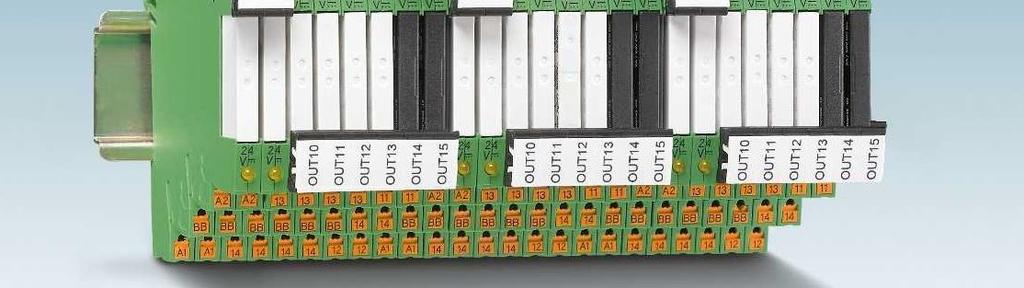
139 452 PHOENIX CONTACT


140 Your web code: #0139 PHOENIX CONTACT 453
141 Stand-alone module Supply Supply voltage 24 V DC Supply voltage range 19.2 V DC V DC Max. input current at U N 120 ma Input data (digital) Number of inputs 8 (2 configurable as analog) Input voltage 24 V DC Description of the input EN , type 3 Input current 0-signal < 1 ma Input current 1-signal typ. 2.5 ma Input data (analog) Number of inputs 2 (IN6 and IN7 are configurable as analog) Input voltage range 0 V V Input resistance > 3.5 k Input data (PLC-INTERFACE) Number of inputs 8 Output data (for controlling PLC-INTERFACE) Number of outputs 8 Nominal voltage 24 V DC Nominal current 9 ma Realtime clock (basic module only) Buffer time (capacitor) 24 h (capacitor) Realtime clock accuracy ±2 s/d General data Ambient temperature (operation) -20 C C Ambient temperature (storage/transport) -20 C C Permissible humidity (operation) 95 % Clearance and creepage distances between the power circuits DIN EN Rated insulation voltage 50 V Rated surge voltage 0.8 kv Insulation Basic insulation Mounting type Can be plugged onto 8 x PLC-INTERFACE Degree of protection IP20 Screw connection solid / stranded / AWG mm² / mm² / Push-in connection solid / stranded / AWG mm² / mm² / Description PLC-V8C plug-in logic modules With screw connection PLC-V8C/SC-24DC/SAM With push-in connection PLC-V8C/PT-24DC/SAM PHOENIX CONTACT
142 Basic module Extension module 24 V DC 24 V DC 19.2 V DC V DC 19.2 V DC V DC 120 ma 65 ma 8 (2 configurable as analog) 8 (2 configurable as analog) 24 V DC 24 V DC EN , type 3 EN , type 3 < 1 ma < 1 ma typ. 2.5 ma typ. 2.5 ma 2 (IN6 and IN7 are configurable as analog) 2 (IN6 and IN7 are configurable as analog) 0 V V 0 V V > 3.5 k > 3.5 k V DC 24 V DC 9 ma 9 ma 24 h (capacitor) - ±2 s/d C C -20 C C -20 C C -20 C C 95 % 95 % DIN EN DIN EN V 50 V 0.8 kv 0.8 kv Basic insulation Basic insulation Can be plugged onto 8 x PLC-INTERFACE Can be plugged onto 8 x PLC-INTERFACE IP20 IP mm² / mm² / mm² / mm² / mm² / mm² / mm² / mm² / PLC-V8C/SC-24DC/BM PLC-V8C/SC-24DC/EM PLC-V8C/PT-24DC/BM PLC-V8C/PT-24DC/EM PHOENIX CONTACT 455


143 General data EMC note Class A product, see page 625 Description Color Programming cable Multifunctional memory module for the INTERFACE system CAB-USB A/MICRO USB B/2,0M Flat design IFS-CONFSTICK Description Color PLC logic starter kit 1, 8 integrated inputs (24 V DC) and 8 outputs via PLC-INTERFACE (switching capacity 250 V AC/DC, max. 6 A) PLC-LOGIC-STARTERKIT PHOENIX CONTACT

144 General data EMC note Class A product, see page 625 Description Color IFS gateway for PROFIBUS DP green EM-PB-GATEWAY-IFS RS-232 green EM-RS232-GATEWAY-IFS RS-485 green EM-RS485-GATEWAY-IFS Modbus/TCP green EM-MODBUS-GATEWAY-IFS DeviceNet green EM-DNET-GATEWAY-IFS CANopen green EM-CAN-GATEWAY-IFS PROFINET green EM-PNET-GATEWAY-IFS Ethernet/IP green EM-ETH-GATEWAY-IFS Programming adapter for configuring modules with S-PORT interface Cable length: 3 m IFS-USB-DATACABLE DIN rail connector green ME 22,5 TBUS 1,5/ 5-ST-3,81 GN Connecting cable for connecting PLC logic with the ME 22,5 TBUS DIN rail connector, cable length: 0.3 m PLC-V8C/CAB/TBUS/0,3M PHOENIX CONTACT 457
145 Push-in connection Screw connection Relay output 1 PDT, output data 6 A, 250 V AC/DC PLC-RPT-24DC/ PLC-RSC-24DC/ PDT, output data 50 ma, 36 V DC, gold contact PLC-RPT-24DC/21AU PLC-RSC-24DC/21AU N/O contact, output data 6 A, 250 V AC/DC, actuator type PLC-RPT-24DC/1/ACT PLC-RSC-24DC/1/ACT N/O contact with switch, output data 6 A, 250 V AC/DC PLC-RPT-24UC/1/S/H PLC-RSC-24UC/1/S/H Solid-state relay output Output data 100 ma, 3 V DC - 48 V DC PLC-OPT-24DC/48DC/ PLC-OSC-24DC/48DC/ Output data 3 A, 3 V DC - 33 V DC PLC-OPT-24DC/24DC/ PLC-OSC-24DC/24DC/ Output data 750 ma, 24 V AC V AC PLC-OPT-24DC/230AC/ PLC-OSC-24DC/230AC/ Output data 3 A, 3 V DC - 33 V DC, actuator type PLC-OPT-24DC/24DC/2/ACT PLC-OSC-24DC/24DC/2/ACT Output data 750 ma, 24 V AC V AC, actuator type PLC-OSC-24DC/230AC/1/ACT Output data 1 A, 12 V DC V DC PLC-OPT-24DC/300DC/ PLC-OSC-24DC/300DC/ Output data 10 A, 3 V DC - 33 V DC PLC-OPT-24DC/24 DC/10/R PLC-OSC-24DC/24DC/10/R Output data 500 ma, 3 V DC - 48 V DC, electronic PDT PLC-OPT-24DC/48DC/500/W PLC-OSC-24DC/48DC/500/W Output data, TTL, 50 ma, 5 V DC PLC-OPT-24DC/TTL PLC-OSC-24DC/TTL Relay input Input voltage 24 V DC PLC-RPT-24DC/1AU/SEN PLC-RSC-24DC/1AU/SEN Input voltage 120 V AC/DC PLC-RPT-120UC/1AU/SEN PLC-RSC-120UC/1AU/SEN Input voltage 230 V AC/DC PLC-RPT-230UC/1AU/SEN PLC-RSC-230UC/1AU/SEN Input voltage 5 V DC (basic terminal block without relay) PLC-BSC- 5DC/ 1/SEN Relay for 5 V DC basic terminal block REL-MR-4,5DC/21AU Solid-state relay input Input voltage 24 V DC PLC-OPT-24DC/48DC/100/V8C/SEN PLC-OSC-24DC/48DC/100/V8C/SEN Input voltage 120 V AC/DC PLC-OPT-120UC/48DC/100/V8C/SEN PLC-OSC-120UC/48DC/100/V8C/SEN Input voltage 230 V AC/DC PLC-OPT-230UC/48DC/100/V8C/SEN PLC-OSC-230UC/48DC/100/V8C/SEN Dummy or reserve Basic terminal blocks output PLC-BPT-24DC/ PLC-BSC-24DC/ Basic terminal blocks input PLC-BPT-24DC/1/SEN PLC-BSC-24DC/1/SEN PHOENIX CONTACT


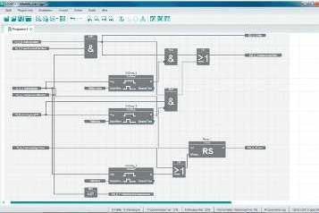


146 PHOENIX CONTACT 459
147 460 PHOENIX CONTACT
148 Notes: of housing: Polyamide PA non-reinforced, color: green. Marking systems and mounting material See Catalog 5 For the protection of relay coils and contacts, inductive loads must be dampened with an efficient protection circuit. For other EB...DIK... insertion bridges refer to page 467 For medium to large loads 1 PDT (21) Input data Permissible range (with reference to U N ) Typ. input current at U N [ma] 9 Response/release time at U N [ms] 8 / 5 Input protection: Yellow LED, protection against polarity reversal, freewheeling diode Output data Contact type 1 PDT Contact material AgSnO Max. switching voltage 250 V AC/DC Min. switching voltage 12 V AC/DC Limiting continuous current 6 A Max. inrush current 6 A Min. switching current 10 ma Max. interrupting rating, ohmic load 24 V DC 140 W 48 V DC 20 W 60 V DC 18 W 110 V DC 23 W 220 V DC 40 W 250 V AC 1500 VA General data Test voltage (winding/contact) 4 kv AC (50 Hz, 1 min.) Ambient temperature (operation) -20 C C Mechanical service life Approx cycles Standards/regulations IEC 60664, EN 50178, IEC Connection data solid / stranded / AWG mm² / mm² / Dimensions W / H / D 6.2 mm / 80 mm / 56 mm EMC note Class A product, see page 625 Description Relay terminal block with power relay Cover Insertion bridge, for middle and lower levels Input voltage U N 24 V DC DEK-REL-G24/ Accessories D-DEK 1,5 GN No. of Color pos. 80 blue EB 80- DIK BU 26 A red EB 80- DIK RD 26 A white EB 80- DIK WH 26 A PHOENIX CONTACT 461
149 Notes: of housing: Polyamide PA non-reinforced, color: green. Marking systems and mounting material See Catalog 5 For the protection of relay coils and contacts, inductive loads must be dampened with an efficient protection circuit. For other EB...DIK... insertion bridges refer to page 467 for small to medium loads 1 N/O contact (1) Pin configuration, DEK-REL-...AKT Input data Permissible range (with reference to U N ) Typ. input current at U N [ma] Response/release time at U N [ms] 8 / 15 5 / 15 Input protection: Yellow LED, bridge rectifier Output data Contact type 1 N/O contact (double contact) Contact material AgNi, hard gold-plated Max. switching voltage 250 V AC / 125 V DC Min. switching voltage 0.1 V Limiting continuous current 3 A (5 A up to 35 C at 24 V DC) Max. inrush current 5 A Min. switching current 1 ma Max. interrupting rating, ohmic load 24 V DC 72 W 48 V DC 60 W 60 V DC 50 W 110 V DC 50 W 250 V AC 750 VA General data Test voltage (winding/contact) 2 kv AC (50 Hz, 1 min.) Ambient temperature (operation) -20 C C Mechanical service life Approx. 2 x 10 7 cycles Standards/regulations IEC 60664, EN 50178, IEC Connection data solid / stranded / AWG mm² / mm² / Dimensions W / H / D 6.2 mm / 80 mm / 56 mm EMC note Class A product, see page 625 Description Relay terminal block with miniature relay Terminal block, with three through contacts, for mounting on NS For busbar feeding Cover Insertion bridge, for middle and lower levels Input voltage U N 5 V AC/DC DEK-REL- 5/I/ V AC/DC DEK-REL- 24/I/ Accessories D-DEK 1,5 GN No. of Color pos. 80 blue EB 80- DIK BU 26 A red EB 80- DIK RD 26 A white EB 80- DIK WH 26 A Pin configuration DEK-REL-...SEN 462 PHOENIX CONTACT
150 for small to medium loads 1 N/O contact (1) for small to medium loads 1 N/O contact (1) for small to medium loads 1 N/O contact (1) / 15 5 / 15 5 / 15 5 / 15 Yellow LED, bridge rectifier Yellow LED, bridge rectifier Yellow LED, bridge rectifier 1 N/O contact (double contact) 1 N/O contact 1 N/O contact AgNi, hard gold-plated AgNi, hard gold-plated AgNi, hard gold-plated 250 V AC / 125 V DC 250 V AC / 125 V DC 250 V AC / 125 V DC 0.1 V 0.1 V 0.1 V 3 A (5 A up to 35 C at 24 V DC) 3 A (5 A up to 35 C at 24 V DC) 3 A (5 A up to 35 C at 24 V DC) 5 A 5 A 5 A 1 ma 1 ma 1 ma 72 W 72 W 72 W 60 W 60 W 60 W 50 W 50 W 50 W 50 W 50 W 50 W 750 VA 750 VA 750 VA 2 kv AC (50 Hz, 1 min.) 2 kv AC (50 Hz, 1 min.) 2 kv AC (50 Hz, 1 min.) -20 C C -20 C C -20 C C Approx. 2 x 10 7 cycles Approx. 2 x 10 7 cycles Approx. 2 x 10 7 cycles IEC 60664, EN 50178, IEC IEC 60664, EN 50178, IEC IEC 60664, EN 50178, IEC mm² / mm² / mm² / mm² / mm² / mm² / mm / 80 mm / 56 mm 6.2 mm / 80 mm / 56 mm 6.2 mm / 80 mm / 56 mm Class A product, see page 625 Class A product, see page 625 Class A product, see page 625 DEK-REL- 5/O/ DEK-REL- 24/O/ DEK-REL- 24/1/AKT DEK-REL- 24/1/SEN Accessories Accessories Accessories DIKD 1, DIKD 1, D-DEK 1,5 GN D-DEK 1,5 GN D-DEK 1,5 GN EB 80- DIK BU 26 A EB 80- DIK BU 26 A EB 80- DIK BU 26 A EB 80- DIK RD 26 A EB 80- DIK RD 26 A EB 80- DIK RD 26 A EB 80- DIK WH 26 A EB 80- DIK WH 26 A EB 80- DIK WH 26 A PHOENIX CONTACT 463
151 Notes: of housing: Polyamide PA non-reinforced, color: green. Marking systems and mounting material See Catalog 5 For the protection of input and output, inductive loads must be dampened with an effective protection circuit. For other EB...DIK... insertion bridges refer to page 467 with DC voltage output max. = 100 ma Derating curve for DEK-OV...24DC/3 and DEK-OV-24DC/24DC/3/AKT Ambient temperature [ C] Horizontal mounting Vertical mounting Ambient temperature [ C] 464 PHOENIX CONTACT Derating curve for DEK-OV-24DC/24DC/10 Derating curve for DEK-OV...240AC/800 Ambient temperature [ C] Input data Permissible range (with reference to U N ) Switching level with reference to U N 1 signal ("H") signal ("L") Typ. input current at U N [ma] Transmission frequency f limit [Hz] Input circuit AC Yellow LED, protection against polarity reversal, surge protection Input circuit DC Yellow LED, protection against polarity reversal Output data Operating voltage range 3 V DC V DC Periodic peak reverse voltage - Limiting continuous current 100 ma Min. load current - Surge current - Leakage current in off state - Max. load value - Output protection Protection against polarity reversal, freewheeling diode Voltage drop at max. limiting continuous current 0.9 V General data Test voltage input/output 2.5 kv (50 Hz, 1 min.) Ambient temperature (operation) -20 C C Standards/regulations IEC 60664, EN 50178, IEC Pollution degree / surge voltage category 2 / III Connection data solid / stranded / AWG mm² / mm² / Dimensions W / H / D 6.2 mm / 80 mm / 56 mm EMC note Class A product, see page 625 Description Solid-state input relay Solid-state power relay Actuator principle Insertion bridge, for middle and lower levels Input voltage U N 5 V DC DEK-OE- 5DC/ 48DC/ V DC DEK-OE- 12DC/ 48DC/ V DC DEK-OE- 24DC/ 48DC/ V DC DEK-OE- 60DC/ 48DC/ V AC DEK-OE-120AC/ 48DC/ V AC DEK-OE-230AC/ 48DC/ V DC 12 V DC 24 V DC 24 V DC Accessories No. of Color pos. 80 blue EB 80- DIK BU 26 A red EB 80- DIK RD 26 A white EB 80- DIK WH 26 A
152 with DC voltage output max. = 3 A with DC voltage output max. = 10 A with AC voltage output max. = 800 ma Yellow LED, protection against polarity reversal Yellow LED, protection against polarity reversal, surge protection Yellow LED, protection against polarity reversal, surge protection 3 V DC V DC 5 V DC V DC 10 V AC V AC (50/60 Hz) V 3 A (see derating curve) 10 A (see derating curve) 0.8 A (see derating curve) ma A (t = 20 ms) 30 A (t = 10 ms) ma A 2 s Protection against polarity reversal, surge protection Protection against polarity reversal, surge protection RCV circuit 0.2 V < 50 mv 1 V 2.5 kv (50 Hz, 1 min.) 2.5 kv (50 Hz, 1 min.) 2.5 kv (50 Hz, 1 min.) -20 C C -20 C C -20 C C IEC 60664, EN 50178, IEC IEC 60664, EN 50178, IEC IEC 60664, EN 50178, IEC / III 2 / III 2 / III mm² / mm² / mm² / mm² / mm² / mm² / mm / 80 mm / 56 mm 6.2 mm / 80 mm / 56 mm 6.2 mm / 80 mm / 56 mm Class A product, see page 625 Class A product, see page 625 DEK-OV- 5DC/ 24DC/ DEK-OV- 5DC/ 24DC/ DEK-OV- 5DC/240AC/ DEK-OV- 12DC/ 24DC/ DEK-OV- 12DC/ 24DC/ DEK-OV- 12DC/240AC/ DEK-OV- 24DC/ 24DC/ DEK-OV- 24DC/ 24DC/ DEK-OV- 24DC/240AC/ DEK-OV- 24DC/ 24DC/ 3/AKT Accessories Accessories Accessories EB 80- DIK BU 26 A EB 80- DIK BU 26 A EB 80- DIK BU 26 A EB 80- DIK RD 26 A EB 80- DIK RD 26 A EB 80- DIK RD 26 A EB 80- DIK WH 26 A EB 80- DIK WH 26 A EB 80- DIK WH 26 A PHOENIX CONTACT 465
153 466 PHOENIX CONTACT

154 Notes: of housing: Polyamide PA non-reinforced, color: green. Marking systems and mounting material See Catalog 5 For the protection of input and output, inductive loads must be dampened with an effective protection circuit. Relay module with manual switch and integrated relay Input data Permissible range (with reference to U N ) Typ. input current at U N [ma] 6.5 Response/release time at U N [ms] 5 / 15 Input protection: Yellow LED, bridge rectifier Output data Contact type 1 N/O contact Contact material AgNi, hard gold-plated Max. switching voltage 250 V AC / 125 V DC Min. switching voltage 0.1 V Limiting continuous current 3 A (5 A up to 35 C at 24 V DC) Max. inrush current 5 A Min. switching current 1 ma Max. interrupting rating, ohmic load 24 V DC 72 W 48 V DC 60 W 60 V DC 50 W 110 V DC 50 W 250 V AC 750 VA General data Test voltage (winding/contact) 2 kv AC (50 Hz, 1 min.) Ambient temperature (operation) -20 C C Mechanical service life Approx. 2 x 10 7 cycles Standards/regulations IEC 60664, EN 50178, IEC Connection data solid / stranded / AWG mm² / mm² / Dimensions W / H / D 6.2 mm / 80 mm / 61 mm EMC note Class A product, see page 625 Description Relay module with power relay Input voltage U N 24 V AC/DC DEK-REL- 24/1/S Accessories Cover D-DEK 1,5 GN Insertion bridge No. of pos. Color 2 red EB 2- DIK RD red EB 3- DIK RD red EB 4- DIK RD red EB 5- DIK RD red EB 10- DIK RD blue EB 2- DIK BU blue EB 3- DIK BU blue EB 4- DIK BU blue EB 5- DIK BU blue EB 10- DIK BU blue EB 80- DIK BU red EB 80- DIK RD PHOENIX CONTACT 467
155 1 PDT, plug-in relay 1 PDT, soldered-in relay Notes: Load current diagrams, see page 427 Input data Permissible range (with reference to U N ) Typ. input current at U N [ma] Response/release time at U N [ms] 8 / 10 8 / / 8 10 / 8 Input protection: Yellow LED, bridge rectifier, surge protection Yellow LED, bridge rectifier, surge protection Output data Contact type Single contact, 1-PDT Double contact, 1 PDT Single contact, 1-PDT Double contact, 1 PDT Contact material AgNi Au AgNi AgPd60, hard gold-plated Max. switching voltage 250 V AC/DC 30 V AC / 36 V DC 250 V AC/DC 30 V AC / 36 V DC Limiting continuous current 6 A 0.5 A 6 A 0.5 A Max. inrush current 8 A 0.2 A 8 A 0.2 A Max. interrupting rating, ohmic load 24 V DC 140 W 5 W 95 W 5 W 48 V DC 60 W - 50 W - 60 V DC 45 W - 45 W V DC 35 W - 35 W V DC 55 W - 55 W V AC 1500 VA VA - General data Test voltage (winding/contact) 2.5 kv AC (50 Hz, 1 min.) 2.5 kv AC (50 Hz, 1 min.) Ambient temperature (operation) -20 C C -20 C C Mechanical service life Approx. 2 x 10 7 cycles Approx. 2 x 10 7 cycles Standards/regulations IEC 60664, EN 50178, IEC IEC 60664, EN 50178, IEC Connection data solid / stranded / AWG - / - / mm² / mm² / Dimensions W / H / D 20.8 mm / 42.5 mm / 112 mm 22.5 mm / 75 mm / 62.5 mm Description Relay module with power contact relay Relay module with multi-layer contact relay Input voltage U N 24 V AC ST-REL3-KG 24/21/SO V AC ST-REL3-KG120/21/SO V AC ST-REL3-KG230/21/SO EMG 22-REL/KSR-230/21/ SO V AC ST-REL3-KG 24/21/AU/SO V AC ST-REL3-KG120/21/AU/SO V AC ST-REL3-KG230/21/AU/SO EMG 22-REL/KSR-230/21/AU/SO Accessories Basic terminal block, complete with end cover URELG Accessories Equipment marker EMG-GKS PHOENIX CONTACT

156 Notes: of housing: ST-REL: Polyamide non-reinforced PA, color: bottom part gray, hood green EMG: Polyamide fiber reinforced PA-F, color: green. DEK: Polyamide non-reinforced PA, color: green. Marking systems and mounting material See Catalog 5 For derating curve, refer to page 425 Solid-state input relay 100 ma, maximum Solid-state power relay Max. 2 A Input data Permissible range (with reference to U N ) Switching level 1 signal ("H") [V DC] signal ("L") [V DC] Typ. input current at U N [ma] Typ. switch-on time at U N [ms] Typ. shutdown time at U N [ms] Transmission frequency f limit [Hz] Input circuit AC Yellow LED, surge protection, RC element Input circuit DC Protection against polarity reversal Output data Max. switching voltage 48 V DC 48 V DC Min. switching voltage 3 V DC 12 V DC Limiting continuous current 100 ma 2 A (see derating curve) Max. inrush current - 5 A (t = 1 s) Output circuit 3-conductor, ground-referenced 3-conductor, ground-referenced Output protection Protection against polarity reversal, freewheeling Protection against polarity reversal, surge protection Voltage drop at max. limiting continuous current 0.9 V 1.1 V General data Test voltage input/output 2.5 kv AC 3.5 kv AC Ambient temperature (operation) 0 C C -10 C C Standards/regulations IEC 60664, EN 50178, IEC IEC 60664, EN 50178, IEC Pollution degree / surge voltage category 2 / III 2 / III Mounting position / mounting any / can be aligned without spacing - / aligned without spacing: horizontal/not aligned: any Connection data solid / stranded / AWG mm² / mm² / mm² / mm² / Dimensions W / H / D 6.2 mm / 80 mm / 56 mm 17.5 mm / 75 mm / 102 mm EMC note Class A product, see page 625 Description Solid-state power relay Input voltage U N 24 V DC EMG 17-OV- 24DC/ 48DC/ V AC DEK-OE-230AC/ 48DC/100/SO Accessories Accessories Equipment marker EMG-GKS PHOENIX CONTACT 469
157 Notes: of housing: Polycarbonate fiber reinforced PC-F, color: green or black. Marking systems and mounting material See Catalog 5 Input data Permissible range (with reference to U N ) Typ. input current at U N [ma] 28 Response/release time at U N [ms] 13 / 15 Input protection: Yellow LED, freewheeling diode Output data Contact type 1 N/O contact with lead contact Contact material AgCdO Max. switching voltage 250 V AC Limiting continuous current 10 A Max. inrush current 80 A (20 ms) Max. interrupting rating, ohmic load 24 V DC - 48 V DC - 60 V DC V DC V DC V AC 2500 VA General data Test voltage (winding/contact) 2.5 kv AC (50 Hz, 1 min.) Ambient temperature (operation) -20 C C Mechanical service life Approx cycles Standards/regulations IEC 60664, EN 50178, IEC Mounting position / mounting - / horizontal without spacing, vertical with spacing medium to large loads 1 N/O contact (1) Connection data solid / stranded / AWG - / - / - Dimensions W / H / D 20.8 mm / 42.5 mm / 112 mm Description Relay module with power contact relay + wolfram lead contact Input voltage U N 24 V DC ST-REL3-KG 24/ 1/SO Relay module with power contact relay, with two inputs for manual, automatic 24 V DC Accessories Basic terminal block, complete with end cover URELG Equipment marker 470 PHOENIX CONTACT


158 medium to large loads 1 N/O contact (1) medium to large loads 1 N/O contact (1) / 9 / Yellow LED, freewheeling diode Automatic: yellow LED, manual: red LED, freewheeling diode, protection against polarity reversal 1 N/O contact with lead contact Single contact, 1 N/O contact AgCdO AgSnO 250 V AC 250 V AC/DC 10 A 10 A 80 A (20 ms) 120 A (20 ms) W W - 85 W - 70 W - 90 W 2500 VA 2500 VA 4 kv AC (50 Hz, 1 min.) 4 kv AC (50 Hz, 1 min.) -20 C C -20 C C Approx cycles 3 x 10 7 cycles IEC 60664, EN 50178, IEC IEC 60664, EN 50178, IEC any any mm² / mm² / mm² / mm² / mm / 75 mm / 62.5 mm 17.5 mm / 75 mm / 62.5 mm EMG 17-REL/KSR-G 24/SO38 BK Accessories EMG 17-REL/KSR-G 24/2E/SO Accessories EMG-GKS EMG-GKS PHOENIX CONTACT 471
 0.8 0 signal (\"L\") 0.4 Typ.")
159 Notes: of insulating housing: polyamide PA non-reinforced, color: bottom part gray, hood green Ground (minus) potential from the input and output of the optocoupler should not be connected. AC loads must be protected with a varistor or an RC element. with AC voltage output max. = 3 A Input data Switching level with reference to U N 1 signal ("H") signal ("L") 0.4 Typ. input current at U N [ma] 7 Transmission frequency f limit [Hz] 10 Input protection: Yellow LED, protection against polarity reversal, RC element Output data Operating voltage 400 V AC Operating voltage range 24 V AC V AC Periodic peak reverse voltage 800 V Limiting continuous current 3 A (see derating curve) Min. load current 50 ma Surge current 125 A (t = 10 ms) Residual voltage drop at "H" 1.2 V Leakage current in off state approx. 12 ma Output protection Surge protection, RC element General data Test voltage input/output 2.5 kv AC Ambient temperature (operation) 0 C C Standards/regulations IEC 60664, EN 50178, IEC Pollution degree / surge voltage category 2 / III Mounting position / mounting Horizontal DIN rail / - Dimensions W / H / D 20.8 mm / 42.5 mm / 112 mm Description Solid-state power relay Input voltage U N 24 V DC ST-OV3-24DC/400AC/ Accessories Basic terminal block, complete with end cover URELG Derating curve for ST-OV 3-24DC/400AC/3 Ambient temperature [ C] Aligned without spacing Aligned with 20 mm spacing 472 PHOENIX CONTACT
160 Notes: of housing: Polyamide PA non-reinforced, color: bottom part gray, hood green Marking systems and mounting material See Catalog 5 For load current diagram, see page 427 Derating curve, time/current characteristic curves, and state diagram, see page 427 with short-circuit-proof DC voltage output max. = 1 A or 4 A Input data ST-OV4-24DC/ 24DC/1-PRO ST-OV4-24DC/ 24DC/4-PRO Operating voltage 24 V DC ± 50% Switching level 1 signal ("H") 8.5 V DC 0 signal ("L") 5 V DC Typ. input current at U N 6.5 ma Transmission frequency f limit 100 Hz Reset period after short-circuit / overload shutdown 1 ms Input circuit Yellow LED, polarity protection diode Output data signaling contact / CONTROL Operating voltage range 5 V DC V DC Limiting continuous current 50 ma Residual voltage drop at "H" 1.5 V Output protection Polarity protection diode Output circuit 3-conductor, ground-referenced Output data load contact Operating voltage range 18 V DC V DC Limiting continuous current 1 A (see derating curve) 4 A (see derating curve) Min. load current 1 ma Residual voltage drop at "H" 300 mv 200 mv Open circuit alarm with load current < 100 µa Overload disconnection (~ 1.4 x continuous current) 100 ms (see the time-current characteristic curve) Short-circuit disconnection < 200 µs (see the time-current characteristic curve) Current limitation at short-circuits approx. 25 A approx. 70 A Switching time t in /t out 300 µs / 700 µs Output protection Red LED, freewheeling diode Output circuit 3-conductor, ground-referenced General data Test voltage input/output 2.5 kv AC Test voltage output/output 2.5 kv AC Rated surge voltage Basic insulation Ambient temperature (operation) 0 C C Standards/regulations IEC / EN / IEC Screw connection solid / stranded / AWG mm² / mm² / Dimensions W / H / D 27 mm / 63.5 mm / 114 mm Description Output current Power circuit breaker solid-state relay, with signal logic 1 A ST-OV4-24DC/ 24DC/1-PRO A ST-OV4-24DC/ 24DC/4-PRO Accessories Basic terminal block, complete with end cover UDK-RELG PHOENIX CONTACT 473
 0.8-1.")
161 Notes: of housing: Polyamide PA non-reinforced, color: green. Marking systems and mounting material See Catalog 5 With DC voltage output Transmission frequency 100 khz Input data Permissible range (with reference to U N ) Switching level with reference to U N 1 signal ("H") signal ("L") Typ. input current at U N [ma] 7 6 Typ. switch-on time at U N [µs] Typ. shutdown time at U N [µs] 2 2 Transmission frequency f limit [khz] Input protection: Yellow LED, protection against polarity reversal, surge protection Output data Operating voltage range 4 V DC V DC Limiting continuous current 50 ma Quiescent current 4.3 ma Residual voltage drop at "H" 0.5 V DC Output circuit 3-conductor, ground-referenced Output protection Surge protection General data Test voltage input/output 2.5 kv AC Ambient temperature (operation) -20 C C Standards/regulations IEC 60664, EN 50178, IEC Pollution degree / surge voltage category 2 / II Connection data solid / stranded / AWG mm² / mm² / Dimensions W / H / D 6.2 mm / 80 mm / 56 mm EMC note Class A product, see page 625 Description Solid-state input relay Input voltage U N 5 V DC DEK-OE- 5DC/ 24DC/100KHZ V DC DEK-OE- 24DC/ 24DC/100KHZ PHOENIX CONTACT
162 With DC voltage output push-pull Transmission frequency 100 khz With DC voltage output push-pull Transmission frequency 100 khz Yellow LED, protection against polarity reversal, surge protection Yellow LED, protection against polarity reversal, surge protection 4 V DC V DC 14 V DC V DC 50 ma 50 ma 8.5 ma 15 ma 1.2 V DC 2.2 V DC 3-conductor push-pull, ground referenced 3-conductor push-pull, ground referenced Surge protection Surge protection 2.5 kv AC 2.5 kv AC -20 C C -20 C C IEC 60664, EN 50178, IEC IEC 60664, EN 50178, IEC / II 2 / II mm² / mm² / mm² / mm² / mm / 80 mm / 56 mm 6.2 mm / 80 mm / 56 mm Class A product, see page 625 Class A product, see page 625 DEK-OE- 5DC/ 5DC/100KHZ-G DEK-OE- 5DC/ 24DC/100KHZ-G DEK-OE- 24DC/ 5DC/100KHZ-G DEK-OE- 24DC/ 24DC/100KHZ-G PHOENIX CONTACT 475
163 Notes: of housing: Polyamide PA non-reinforced, color: green. Marking systems and mounting material See Catalog 5 For inductive proximity sensors acc. to NAMUR Supply Input supply nominal voltage U VN 18.5 V DC V DC (U VN, see derating curve) Derating curve for EIK 1-SVN 24 P Ambient temperature [ C] Ripple in acc. with DIN Current consumption I Imax 70 ma (at 50 ma output current) Input circuit Green LED, polarity protection diode Control circuit No-load voltage 8.2 V DC ±10 % Switching points in accordance with EN : 2.1 ma (in conductive state) 1.2 ma (in blocking state) 6.3 ma ma (in the event of a short-circuit) 0 ma ma (in the event of an open circuit) Switching hysteresis approx. 0.2 ma Internal resistance approx. 1 k Output protection visual short-circuit and open circuit check with LED (red), 12 V Zener diode Signal output Max. output current I Omax 50 ma Residual voltage U R with I Omax 1.5 V (U R ) Output voltage U O 100 mv (in conductive state) U VN - U R ; in blocking state Output protection 36 V Zener diode as freewheeling diode General data Ambient temperature (operation) -25 C C Transmission frequency (INPUT/OUTPUT) 1 khz Input pulse length 0.5 ms Input pause length 0.5 ms Standards/regulations IEC 60664, EN , EN Pollution degree / Surge voltage category 2 / III Application 1 Screw connection solid / stranded / AWG mm² / mm² / Dimensions W / H / D 6.2 mm / 80 mm / 56 mm EMC note Class A product, see page 625 NAMUR initiator Description Switching amplifier electronic terminal block, for inductive proximity initiators as per NAMUR, with light indicators for sensor signal and faults EIK1-SVN-24P Application 2 Accessories Terminal block, with three through contacts, for mounting DIKD 1, on NS Double-level terminal block, with pre-assembled resistors UKK 5-2R/NAMUR Insertion bridge EB...-DIK... at DEK-REL... Limit switch 476 PHOENIX CONTACT
 Continuous current 200 ma Residual voltage drop < 1 V Leakage current < 1 ma Max.")
164 Notes: of housing: Polyamide PA non-reinforced, color: green. Marking systems and mounting material See Catalog 5 Supply voltage 20 V DC V DC (U V ) Continuous current 200 ma Residual voltage drop < 1 V Leakage current < 1 ma Max. transmission frequency 15 khz NPN input/pnp output Switch-on threshold < 5 V (at U V = 24 V; < (U V - 19 V)) Switch-off threshold > 15 V (at U V = 24 V; > (U V - 9 V)) Min. limit values -2 V Max. limit values 26 V (at U V = 24 V; U V + 2 V) Control circuit Switch-on threshold > 19 V Switch-off threshold < 9 V Min. limit values -2 V Max. limit values 26 V (at U V = 24 V; U V + 2 V) General data Ambient temperature (operation) -20 C C Standards/regulations IEC Basic insulation Pollution degree / Surge voltage category 2 / II Screw connection solid / stranded / AWG mm² / mm² / Dimensions W / H / D 6.2 mm / 80 mm / 56 mm Description Inverter module DEK-TR/INV Connection examples: NPN output Load PNP output Load PHOENIX CONTACT 477
PLC INTERFACE With Leakage Current and Interference Voltage Suppression
 PLC INTERFACE With Leakage Current and Interference Voltage Suppression PLC- SO46 1. PLC INTERFACE, the super thin, plug-in, and flexible modular interface system with a user-friendly jumper system, now
relais A mark Relay modules
 Relay modules relais Introduction to relay technology Modular DIN rail mounted relays Plug-in DIN rail mounted relays Multiple chassis mounted relays Timer relays The relay modules offer features such
60 Series - General purpose relays 6-10 A. Features Plug-in mount 10 A General purpose relay
 Series - General purpose relays - 0 A Features Plug-in mount 0 A General purpose relay.. & pole changeover contacts Cadmium Free contacts (preferred version) AC coils & DC coils UL Listed (certain relay/socket
Relay modules, Relay sockets, Plug relays
 , Relay sockets, Plug relays General information Relay input side (coil) Single relays housed in slim, rail mounting enclosures taking up the minimum of space. Multiple relays (up to 24) in compact rail
2 Pole CO, 8 A Plug-in 2 CO (DPDT) 1 CO (SPDT) 8/15 16/25* 250/ /400 2,000 4, /0.5/ /0.5/ (5/5) 300 (10/5)
 1 CO (SPDT) 8/15 16/25* 250/ /400 2,000 4, /0.5/ /0.5/ (5/5) 300 (10/5)") 46 Series - Relays for railway applications 8-16 A 46 SERIES Features Plug-in power relays: 8 A, 2 pole 16 A, 1 pole Complies with EN 45545-2:2013 (protection against fire of materials), EN 61373 (resistance
46 Series - Relays for railway applications 8-16 A 46 SERIES Features Plug-in power relays: 8 A, 2 pole 16 A, 1 pole Complies with EN 45545-2:2013 (protection against fire of materials), EN 61373 (resistance
General data. Technical data DIKD 1,5. General. Dimensions
 General data Order number 2715979 Type DIKD 1,5 Barcode number 4017918061722 Unit pack 50 Pcs. Customs tariff 85369010000 Technical data General Number of levels 3 Number of connections 6 Color gray Insulating
DIK 1,5 General data Technical data General
 General data Order number 2715966 Type DIK 1,5 Barcode number 4017918061715 Unit pack 50 Pcs. Customs tariff 85369010000 Technical data General Number of levels 3 Number of connections 4 Color gray Insulating
58 SERIES. Relay interface modules 7-10 A 58.P3 58.P4
 58 58 3 & 4 CO relay interface modules, 31 mm wide with Push-in terminals Ideal interface for PLC and electronic systems 58.P3 58.P4 Type 58.P3 3 CO 10 A Push-in terminals Type 58.P4 4 CO 7 A Push-in terminals
RELOG. All-or-nothing Relay
 RELOG All-or-nothing Relay Table of Content Page RELOG a system with contact components used in control engineering 3 Survey of the 'All-or-nothing relays' device program included in the RELOG system 3
48 SERIES. Relay interface modules 8 A CO forcibly guided contacts relay interface modules,15.8 mm wide Type 48.12
 48 Relay interface modules 8 A 48 2 CO forcibly guided contacts relay interface modules,15.8 mm wide Type 48.12 2 CO 8 A s Relay with forcibly guided contacts according to EN 50205 Type 35 mm rail (EN
Relay interface modules A
 4C SЕRIES Relay interface modules 8-10 - 16 A Escalators Road / tunnel lighting Hoists and cranes Carousel warehouses Control panels Panels for electrical distribution FINDER reserves the right to alter
3.5 mm contact pin pitch 1 Pole 12 A PCB direct or via socket
 41 Series - Low profile PCB relays 8-12 - 16 A Features 41.31 41.52 41.61 1 & 2 Pole - Low profile (15.7 mm height) 41.31-1 Pole 12 A (3.5 mm pin pitch) 41.52-2 Pole 8 A (5 mm pin pitch) 41.61-1 Pole 16
Output of three-phase motors at 50 Hz and 400 V
 RT0, RH Coupling Relays (Interfaces) Description DC operation IEC 0 947 and EN 0 947 (VDE 00) The RT0 coupling relays for switching motors and RH for auxiliary circuits are laid out to the special requirements
PHOENIX CONTACT
 Selective circuit breaker CLIPLINE Data sheet 100464_en_05 PHOENIX CONTACT 2009-11-17 1 Description The electronic circuit breaker, which has a design width of just 12.5 mm, selectively protects all 24
48 Series - Relay interface modules A. Features
 Series - Relay interface modules 8-0 - 6 A Features & Pole relay interface modules, 5.8 mm wide. Ideal interface for PLC and electronic systems.3 - Pole 0 A.5 - Pole 8 A.6 - Pole 6 A coils or sensitive
40 Series - Miniature P.C.B. Relays A
 ..4..4..4 40 Series - Miniature P.C.B. Relays 8-0 - 6 A - P.C.B. or plug-in mount - AC, DC, sensitive DC or single bistable coil versions available - 8 mm, 6 kv (./0 µs) between coil and contacts - Ambient
38 Series - Relay interface modules A
 38 Series - Relay interface modules 0.1-2 - 3-5 - 6-8 A Common features Instant ejection of relay by plastic retaining clip Integral coil indication and protection circuit EMR Electromechanical Relays
38 Series - Relay interface modules A
 38 Series - Relay interface modules 0.1-2 - 3-5 - 6-8 A Common features Instant ejection of relay by plastic retaining clip Integral coil indication and protection circuit 6.2 mm wide EMR - DC, AC or AC/DC
62 Series - Power relays 16 A. Features / /
 6 Series - Power relays 6 A Features 6. / 6.3 6.-0300 / 6.3-0300 Printed circuit mount 6 A Power relay & 3 Pole changeover contacts or NO ( 3 mm contact gap) AC coils & DC coils Reinforced insulation between
38 Series - Relay interface modules A. Features /
 Series - Relay interface modules 0.1-2 - 6-8 A Features 1 Pole - 6 A electromechanical relay interface modules, 6.2 mm wide. Ideal interface for PLC and electronic systems Sensitive DC coil or coil versions
2 pole (1 NO + 1 NC) 1 NO + 1 NC 2 NO + 2 NC, 3 NO + 1 NC 4 NO + 2 NC Rated current / Max. peak current Rated load AC1
 1 NO + 1 NC 2 NO + 2 NC, 3 NO + 1 NC 4 NO + 2 NC Rated current / Max. peak current Rated load AC1") Features 7S.12...5110 7S.14...0220/0310 7S.16..0420 Relay module with forcibly guided contacts 7S.12 with 2 pole (1NO + 1 NC) 7S.14 with 4 pole (2 NO + 2 NC and 3 NO + 1 NC) 7S.16 with 6 pole (4 NO + 2
Features 7S.12...5110 7S.14...0220/0310 7S.16..0420 Relay module with forcibly guided contacts 7S.12 with 2 pole (1NO + 1 NC) 7S.14 with 4 pole (2 NO + 2 NC and 3 NO + 1 NC) 7S.16 with 6 pole (4 NO + 2
38 Series - Relay Interface Modules A
 Series - Relay Interface Modules 0.1-2 - 6 A - Relay interface modules for use with PLC systems, mm wide - Sensitive DC coil or AC/DC coil version - Supplied with integral coil - Instant removal of relay
SIGMA Terminal components
 SIGMA Terminal components Optocouplers Content Terminal components Description, Certifications, Authorizations... 151 Ordering details R1000 / R2000 / R 1500... 152 Ordering details - Series RT, PT, MT...
38 SERIES. Relay interface modules A. EMR Electromechanical Relays. Common features. SSR Solid State Relays. 6.
 38 Relay interface modules 0.1-2 - 3-5 - 6-8 - 16 A 38 Common features Instant ejection of relay by plastic retaining clip Integral coil indication and protection circuit 6.2 mm wide EMR - DC, AC or AC/DC
Miniature Power Relay MSR
 V23061 PCB relay for DC voltage, neutral, monostable Features Used as a switching element for electrical separation between low-power control circuits and power load circuits With 8 mm clearance and creepage
PSR-SCP- 24DC/ESD/5X1/1X2/300
 Extract from the online catalog PSR-SCP- 24DC/ESD/5X1/1X2/300 Order No.: 2981428 Safety relay with adjustable delay time 0-300 s, screw version Commercial data EAN 4017918975227 Pack 1 pcs. Customs tariff
mm wide Low coil power PCB or 93 series sockets. Copper side view. 1 CO (SPDT) 6/10 250/400 1, /0.2/ (12/10) AgNi
 6/10 250/400 1, /0.2/ (12/10) AgNi") 34 Series - Slim electromechanical PCB relays 6 A Features 34.51 Ultra-slim 1 Pole - 6 A relay Printed circuit mount - direct or via PCB socket 35 mm rail mount - via screw or screwless sockets 1 Pole
34 Series - Slim electromechanical PCB relays 6 A Features 34.51 Ultra-slim 1 Pole - 6 A relay Printed circuit mount - direct or via PCB socket 35 mm rail mount - via screw or screwless sockets 1 Pole
MasterINTERFACE 39 Series - Relay interface modules
 Common features Space saving 6.2 mm wide Connections for 16-way jumper link Integral coil indication and protection circuit Secure retention and easy ejection by plastic clip Dual screw head (blade+cross)
EMD-FL-3V-400. Electronic monitoring relay for voltage monitoring in three-phase networks. INTERFACE Data sheet _en_03. 1 Description.
 Electronic monitoring relay for voltage monitoring in three-phase networks INTERFACE Data sheet 102110_en_03 1 Description PHOENIX CONTACT - 09/2009 Features Increasingly higher demands are being placed
IB IL 24/230 DOR 4/W-PC IB IL 24/230 DOR 4/W-PC-PAC
 IB IL 24/230 DOR 4/W-PC IB IL 24/230 DOR 4/W-PC-PAC Inline Terminal With Four Relay Changeover Contacts Data Sheet 6530B 03/2003 $ $ ) The IB IL 24/230 DOR 4/W-PC and IB IL 24/230 DOR 4/W-PC-PAC only differ
PHOENIX CONTACT
 Electronic circuit breaker CLIPLINE Data sheet 102898_en_03 PHOENIX CONTACT 2010-12-17 1 Description The electronic circuit breaker can be used in applications that cover all aspects of the switched-mode
Controls Contactors and Contactor Assemblies Special Applications
 Controls Contactors and Contactor Assemblies Special Applications Price groups 1B, 1H /2 Introduction More information can be found on the Internet: see the opening information, page 13 - Contactors for
2 or 4 pole changeover contact Plug-in/Faston 187
 56 Miniature power relays 56 Plug-in - Power relay, & 4 pole Flange mount option - (Faston 87, 4.8 x 0.5 mm termination) C coils & DC coils Lockable test button and mechanical flag indicator Cadmium Free
The power in relays and timers since Catalogue
 The power in relays and timers since 1954 2012 Catalogue PCB relays Industrial relays Relay interface modules Sockets and accessories Timers Monitoring relays Energy meters Surge protection devices Industrial
Interface relays and optocouplers Product group picture
 Interface relays and optocouplers Product group picture /1 ABB Catalog Electronic Products and Relays 2013/2014 2CDC 1 004 C0209 Interface relays and optocouplers Table of contents Interface Relays and
Contents XR U 1 D 12 G. Poles 1 = 1PDT 2 = 2PDT. Type D = Standard relay S = Octocoupler (solid-state) H = High current
 H = High current") Control Relays and Timers Relay Product Overview.2 Contents Description Standard Terminal Block Relays............ OptoCoupler Terminal Block Relays......... High Current Terminal Block Relays.........
Control Relays and Timers Relay Product Overview.2 Contents Description Standard Terminal Block Relays............ OptoCoupler Terminal Block Relays......... High Current Terminal Block Relays.........
650 PHOENIX CONTACT Courtesy of Power/mation Energy Lane, Saint Paul, MN
 650 PHOENIX CONTACT Monitoring relays, timer relays, function blocks The requirements pertaining to safety and system availability are constantly increasing regardless of the industry. Processes are becoming
MasterINTERFACE 39 Series - Relay interface modules
 MasterINTERFACE 39 Series - Relay interface modules Common features Space saving 6.2 mm wide Connections for 16-way jumper link Integral coil indication and protection circuit Secure retention and easy
Switching relay terminal block; Relay with 1 changeover contact (1u); with miniature switching relay
; with miniature switching relay") relay - Item No: 89-304 Switching relay terminal block; Relay with changeover contact (u); with miniature switching relay Item No: 89-304 Switching relay terminal block; Relay with changeover contact (u);
relay - Item No: 89-304 Switching relay terminal block; Relay with changeover contact (u); with miniature switching relay Item No: 89-304 Switching relay terminal block; Relay with changeover contact (u);
All-or-nothing relay RH(M) 1000 in plug-in case and case for top-hat rail or wall mounting
 1000 in plug-in case and case for top-hat rail or wall mounting") Data Sheet 10/86-2.36-EN All-or-nothing relay RH(M) 1000 in plug-in case and case for top-hat rail or wall mounting Compact robust power relay Type RH(M) 1003: 3 changeover contacts Type RH(M) 1004: 4
Data Sheet 10/86-2.36-EN All-or-nothing relay RH(M) 1000 in plug-in case and case for top-hat rail or wall mounting Compact robust power relay Type RH(M) 1003: 3 changeover contacts Type RH(M) 1004: 4
RU Series Universal Relays
 Full featured universal miniature relays Designed with environment taken into consideration Two terminal styles: plug-in and PCB mount Non-polarized LED indicator available on plug-in relays No internal
UTTB 4. Extract from the online catalog. Order No.:
 Extract from the online catalog UTTB 4 Order No.: 3044814 Feed-through modular terminal block, Cross section: - 6 mm², AWG: 26-10, Connection type: Screw connection, Width: 6.2 mm, Color: gray, Mounting
Relays & Sockets. RF1V Force Guided Relays/SF1V Relay Sockets. Certification Organization/ File Number. UL/c-UL File No.
 RFV Key features: Compact and EN compliant RFV force guided relays Force guided contact mechanism (EN00 Type A TÜV approved) Contact configuration -pole (NO-NC, 3NO-NC) 6-pole (NO-NC, NO-NC, 3NO-3NC) Built-in
Measuring and monitoring relays CM-SRS.1 Current monitoring relays, single-phase AC/DC
 2CDC 251 244 F0t05 Characteristics Monitoring of DC and AC currents: RMS measuring principle One device includes 3 measuring ranges Over- or undercurrent monitoring configurable Hysteresis adjustable from
Relays & Sockets RU Series Universal Relays. With Latching or Momentary Lever. Standard (without lever) Key features:
 Key features:") RU Series Universal Relays Key features: Full featured universal miniature relays Designed with environment taken into consideration Two terminal styles: plug-in and PCB mount Non-polarized LED indicator
RU Series Universal Relays Key features: Full featured universal miniature relays Designed with environment taken into consideration Two terminal styles: plug-in and PCB mount Non-polarized LED indicator
DEK-OV- 12DC/ 24DC/ 3
 Extract from the online catalog DEK-OV- 12DC/ 24DC/ 3 Order No.: 2941387 The illustration shows the version DEK-OV- 24DC/24DC/3 Power optocoupler terminal block, input: 12 V DC, output: 3-30 V DC/3 A,
QUINT-PS-24DC/24DC/10
 QUINT-PS-24/24/10 QUINT - converter, primary switched mode, input: 24 V, output: 24 V /10 A INTERFACE Data Sheet PHOENIX CONTACT - 02/2006 Description The QUINT - converter 24 V/10 A converts the voltage
UTTB 2,5. Extract from the online catalog. Order No.:
 Extract from the online catalog UTTB 2,5 Order No.: 3044636 Feed-through modular terminal block, Cross section: - 4 mm², AWG: 26-12, Connection type: Screw connection, Width: 5.2 mm, Color: gray, Mounting
Type CP-S, CP-C & CP-A Switch mode
 Switch mode power CP-S, CP-C & CP-A Switch mode Characteristics CP-S and CP-C range Output current 5 A, 10 A and 20 A Integrated power reserve of up to 50 % 5 A and 10 A devices with pluggable connecting
SLKK 5. Extract from the online catalog. Order No.:
 Extract from the online catalog SLKK 5 Order No.: 0461018 Double-level terminal block with protective conductor foot, cross section: 0.2-4 mm², width: 6.2 mm, color: Gray Commercial data EAN 4017918002381
Smart Power Relay E I...
 Smart Power Relay E-48-8I... Description The Smart Power Relay E-48-8I.- is a remotely controllable electronic load disconnecting relay with three functions in a single unit: l electronic relay l electronic
Industrial Controls. Catalog IC SIRIUS. Answers for industry.
 Industrial Controls Catalog IC 10 2012 SIRIUS Answers for industry. Contactor Relays Siemens AG 2012 Overview Standards IEC 60947-1, EN 60947-1, IEC 60947--1, EN 60947--1 The 3TH42 and 3TH43 contactor
3.5 mm contact pin pitch 1 Pole 12 A PCB direct or via socket
 8-12 - 16 A Features 41.31 41.52 41.61 1 & 2 Pole - Low profile (15.7 mm height) 41.31-1 Pole 12 A (3.5 mm pin pitch) 41.52-2 Pole 8 A (5 mm pin pitch) 41.61-1 Pole 16 A (5 mm pin pitch) PCB mount - direct
Electronic timer CT-TGD.22
 2CDC 251 097 F0t06 a Rotary switch for the preselection of the time range of the ON time b Potentiometer with direct reading scale for the fine adjustment of the ON time c Rotary switch for the preselection
Pluggable interface relays CR-U Universal relays
 Data sheet Pluggable interface relays CR-U Universal relays Pluggable interface relays are used for electrical isolation, amplification and signal matching between the electronic controlling, e.g. PLC
3.5 mm contact pin pitch 1 Pole 12 A PCB direct or via socket
 41 Low profile PCB relays 8-12 - 16 41 1 & 2 Pole - Low profile (15.7 mm height) 41.31-1 Pole 12 (3.5 mm pin pitch) 41.52-2 Pole 8 (5 mm pin pitch) 41.61-1 Pole 16 (5 mm pin pitch) PCB mount - direct or
EMD-FL-C-10. Current Monitoring Relay. Data Sheet. Functions. Structure 08/2004
 Current Monitoring Relay Data Sheet 08/2004 Functions Structure Current monitoring of direct and alternating current in 1-phase networks with settable threshold values, starting override and response delay
Electronic timer CT-SDS.22 Star-delta change-over with 2 n/o contacts Data sheet
 CDC 0 F0t07 Features Rated control supply voltage -8 V DC, -0 V AC Single-function timer with star-delta change-over One device includes 7 time ranges (0.0 s - 0 min) n/o contacts LEDs for status indication
Switching Devices Contactors and Contactor Assemblies for Switching Motors
 Switching Devices Contactors and Contactor Assemblies for Switching Motors groups 41B, 41H / Introduction Power contactors for switching motors /5 General data /11 SIRIUS RT10 contactors, -pole,... 50
PCB Relays Single Relays
 Power Relay K (Open - Sealed) Features Limiting continuous current 40 A Wide voltage range For high current version refer to Power Relay K-S Typical Applications ABS control Blower fans Car alarm Cooling
Thermistor motor protection relays
 Thermistor motor protection relays Content Benefits and advantages... / 68 Selection table... / 68 Ordering details CM-MSE... / 69 CM-MSS... / 69 CM-MSN... / 7 PTC sensor C0... / 7 Technical data... /
Semiconductor contactors, Solid-state relays
 Semiconductor contactors, Solid-state relays Content Benefits and advantages, approvals... 224 R100.xx semiconductor contactors, single-phase Ordering details... 225 Technical data... 228 Dimensional drawings...
PHOENIX CONTACT - 09/2009
 Electronic miniature circuit-breaker CLIPLINE Data sheet 03906_en_0 PHOENIX CONTACT - 09/2009 Description The EC-E... electronic miniature circuit-breaker selectively protects all 24 V DC load circuits
Safety relays - PSR-SCP- 24DC/ESD/4X1/
 Please be informed that the data shown in this PDF Document is generated from our Online Catalog. Please find the complete data in the user's documentation. Our General Terms of Use for Downloads are valid
77 Series - Modular Solid State Relay 5 A. Features. Timers and Monitoring relays
 Series - Modular Solid State Relay 5 A 77 Features 77.01.x.xxx.8050 77.01.x.xxx.8051 5 A modular SSR, 1 NO output 17.5 mm housing 60 to 240 V AC output (with back to back SCR) 5 kv (1.2/50 μs) insulation
PHOENIX CONTACT - 06/2008. Features. DANGER OF EXPLOSION! Only remove equipment when it is disconnected and not in the potentially explosive area.
 Primary-switched power supply with SFB technology, 1 AC, output current 20 A INTERFACE Data Sheet 103383_en_00 1 Description PHOENIX CONTACT - 06/2008 Features QUINT POWER power supply units highest system
HMI Components. Series. Raised design PCB (with adaptor) Machinery and Automation. Indicator Illuminated pushbutton
 Machinery and Automation. Indicator Illuminated pushbutton") Edition 10/2016 HMI Components 41 Series Characteristics The rectangular design of the Series 41 (18 x 24 mm) makes it especially suited: Raised design PCB (with adaptor) Functions The Series 41 incorporates
Edition 10/2016 HMI Components 41 Series Characteristics The rectangular design of the Series 41 (18 x 24 mm) makes it especially suited: Raised design PCB (with adaptor) Functions The Series 41 incorporates
TRIO-PS/1AC/24DC/ 5. Extract from the online catalog. Order No.:
 Extract from the online catalog TRIO-PS/1AC/24DC/ 5 Order No.: 2866310 DIN rail power supply unit, primary-switched mode, 1-phase, output: 24 V DC / 5 A Commercial data EAN 4046356046640 Pack 1 pcs. Customs
No-wear isolation of potentials in terminal block design
 TERMOPTO Overview No-wear isolation of potentials in terminal block design Space saving solid-state relay with PUSH IN connection technology The TERMOPTO opto modules are characterised by a particularly
QUINT-PS/ 3AC/24DC/10
 Primary-switched power supply with SFB technology, 3 AC, output current 10 A INTERFACE Data sheet 103131_en_01 1 Description PHOENIX CONTACT - 09/2009 Features QUINT POWER power supply units Maximum system
CM-MPS.11, CM-MPS-21, CM-MPS.31 and CM-MPS.41 Data sheet. UL 508, CAN/CSA C22.2 No.14 GL GOST CB scheme CCC
 2CDC 251 048 F0t08 CM-MPS.11 2CDC 251 049 F0t08 CM-MPS.21 Features Monitoring of three-phase mains for phase sequence (can be switched off), phase failure, over- and undervoltage as well as phase unbalance
QUINT-PS/ 3AC/24DC/40
 Primary-switched power supply unit with SFB technology, 3 AC, output current 40 A INTERFACE Data sheet 103133_en_00 1 Description PHOENIX CONTACT - 07/2009 Features QUINT POWER power supply units Maximum
ABB NEW. Multifunctional three-phase monitoring relays. CM-MPS.23 and CM-MPS.43 Data sheet. Features J. Approvals. Marks.
 2CDC 251 052 F0t08 CM-MPS.23 2CDC 251 053 F0t08 CM-MPS.43 - relay status, timing - fault message - fault message Adjustment of the tripping delay t V Adjustment of the threshold value for overvoltage 6
Industrial Controls. SIRIUS 3R_1* in sizes S00/S0 to S12. Catalog Add-On IC 10 AO 2012 SIRIUS. Answers for industry.
 Industrial Controls SIRIUS R_* in sizes S00/S0 to S Catalog Add-On IC 0 AO 0 SIRIUS Answers for industry. Controls Contactors and Contactor Assemblies for Switching Motors Price Groups PG B, H / Introduction
62.22 Copper side view
 62 Power relays 16 62 Printed circuit mount 16 Power relay 2 & 3 Pole changeover contacts or NO ( 3 mm contact gap) C coils & DC coils Reinforced insulation between coil and contacts according to EN 60335-1,
Semiconductor contactors, Solid-state relays
 Semiconductor contactors, Solid-state relays Content Benefits and advantages... 338 Approvals and marks... 338 Semiconductor contactors... 339 Ordering details... 339 R100.xx, single-phase... 339 R300.xx,
QUINT-PS AC/24DC/40
 Power supply unit INTERFACE Data sheet 102315_en_02 1 Description PHOENIX CONTACT 2010-04-23 Features QUINT POWER power supply units for plant and special engineering reliably start heavy loads with high
DPDT MY2N-D2 MY2IN-D2 --- (DC only) 4PDT MY4N-D2 MY4IN-D PDT (bifurcated) MY4ZN-D2 MY4ZIN-D2 --- With built-in CR
 4PDT MY4N-D2 MY4IN-D PDT (bifurcated) MY4ZN-D2 MY4ZIN-D2 --- With built-in CR") General-purpose Relay MY New model Versatile and Function-filled Miniature Power Relay for Sequence Control and Power Switching Applications Models with lockable test buttons now available. Many variations
General-purpose Relay MY New model Versatile and Function-filled Miniature Power Relay for Sequence Control and Power Switching Applications Models with lockable test buttons now available. Many variations
Insulation coordination (EN ) Standards EN Note 24 V DC / 24 V DC 0,1 A. 230 V AC ±10% Power rating 24 V DC ±20 % 140 mw
 Standards EN Note 24 V DC / 24 V DC 0,1 A. 230 V AC ±10% Power rating 24 V DC ±20 % 140 mw") Optos - MIROSERIES MOS / MOZ 3 48 V D / 0.1 A Universal interface between control and sensor/actuator Plug-in cross-connection ZQV 4N Interchangeable solid-state relay 6.1 mm wide Screw or tension clamp
Optos - MIROSERIES MOS / MOZ 3 48 V D / 0.1 A Universal interface between control and sensor/actuator Plug-in cross-connection ZQV 4N Interchangeable solid-state relay 6.1 mm wide Screw or tension clamp
Mini Contactors. Mini Contactor Relays 4-pole 8 Auxiliary Contact Blocks. Interface Contactor Relays. Mini Contactors 10 Auxiliary Contact Blocks
 Mini Contactors Mini Contactor Relays 4-pole 8 Auxiliary Contact Blocks Interface Contactor Relays Mini Contactors 10 Auxiliary Contact Blocks Mini Contactors With Fast On Tab Connectors 12 Mini Contactors
62 Series - Power relays 16 A. Features SERIES / / Printed circuit mount 16 A Power relay
 62 Series - Power relays 16 62 SERIES Features 62.22 / 62.23 62.22-0300 / 62.23-0300 Printed circuit mount 16 Power relay 2 & 3 Pole changeover contacts or NO ( 3 mm contact gap) C coils & DC coils Reinforced
Electronic Circuit Breaker ESS20-0..
 Description Electronic circuit breaker type ES-0.. is designed to ensure selective disconnection of individual loads in systems which are powered by a DC 4 V switch-mode power supply. DC 4 V power supplies,
MINI-PS AC/24DC/1.3
 Power supply unit INTERFACE Data sheet 102894_en_03 1 Description PHOENIX CONTACT 2015-11-17 Features MINI POWER power supplies for MCR technology In measurement and control technology (MCR), modular electronics
QUINT-PS/ 1AC/24DC/20
 Primary-switched power supply with SFB technology, 1 AC, output current 20 A INTERFACE Data sheet 103129_en_04 1 Description PHOENIX CONTACT - 02/2010 Features QUINT POWER power supply units Maximum system
Safety Technique. Emergency Stop Module With Time Delay BH 5928, BI 5928
 Safety Technique safemaster Emergency Stop Module With Time Delay BH 5928, BI 5928 0226419 BH 5928 BI 5928 Function Diagram According to - Performance Level (PL) e and category 4 to E ISO 13849-1 2008
This data sheet is only valid in association with the IL SYS INST UM E user manual.
 Inline counter terminal, version for extreme conditions, 1 counter input, 1 control input, 1 output, 24 V DC, 500 ma Data sheet 106148_en_03 PHOENIX CONTACT 2015-11-04 1 Description The terminal is designed
Electronic timer CT-SDS.22
 CDC 0 F0t07 Features Rated control supply voltage 8 V DC, 0 V AC Single function timer with star delta change over One device includes 7 time ranges (0.0 s 0 min) n/o contacts LEDs for status indication
RJ Series Slim Power Relays
 RJ Series RJ Series Slim Relays Circuit Breakers Terminal Blocks Timers Display Lights Switches & Pilot Lights Compact and rugged power relays. Large switching capacity. Compact housing only.7-mm wide.
VariTrans P D1 TRMS
 Isolation Amplifiers Transmitters Indicators Process Analytics Portable Meters Laboratory Meters Sensors Fittings VariTrans P 41000 D1 TRMS VariTrans P 41000 TRMS AC/DC High-Voltage Transmitters With True
Low profile safety relay with forcibly guided double contacts FEATURES. Relay height, 14.5mm. 4a2b
 Low profile safety relay with forcibly guided double contacts SFN4D RELAY 3.3 33.0 FEATURES Relay complies with EN 020, Type B. Polarized magnet system with snap action function Tolerance ±0.3 mm Weight
ET M3792_a. DC 6, 12, 15, 20, 24 V AC 12, 24, 42, 230 V Voltage range U N
 Control Technique Connecting Module Interface Relay Pluggable HC 09 078 According to DIN EN 18 output contacts with monostable PCB-relay OA 8 Version with bistable PCB-relay OB 9 Contact material with
PHOENIX CONTACT - 05/2008. DANGER OF EXPLOSION! Remove an item only when it is not connected to power or if it is located in the non-explosive area.
 Primary-switched power supply with SFB technology, 1 AC, output current 20 A INTERFACE Data Sheet 103129_en_01 PHOENIX CONTACT - 05/2008 1 Description QUINT POWER power supply units highest system availability
PCB Relays Twin Relays
 Features Limiting continuous current A Easiest PCB routing among all PCB relays Typical Applications Car alarm Door control Door lock Immobilizer Seat control Sun roof Window lifter Wiper control Please
DATASHEET - ETR4-70-A. Delivery program. Timing relay, 2W, 0.05s-100h, multi-function, VAC/DC, potentiometer connection
 DATASHEET - ETR4-70-A Delivery program Timing relay, 2W, 0.05s-100h, multi-function, 24-240VAC/DC, potentiometer connection Part no. ETR4-70-A Catalog No. 031888 Eaton Catalog No. XTTR6A100H70B EL-Nummer
CP-T range Product group picture
 Product group picture /1 ABB Catalog Electronic Products and Relays 1/1 2CDC 110 00 C09 Table of contents CP-T range Product group picture /1 Table of contents /2 Benefits and advantages / Ordering details
CONTA-ELECTRONICS. Relay systems
 CONTA-ELECTRONICS Relay technology continues to play a large role in the reliability of industrial control and automation solutions. Because of their thin design, relay couplers are suitable for use in
4. 2. Electronics Relays and Optos. Catalogue C A T A L O G U E
 C A T A L O G U E 4. 011 01 Electronics Relays and Optos Catalogue Product Portfolio Weidmüller is a leading international provider of solutions for electrical connectivity, transmission and conditioning
Index. Capacitor Switching - 2 Contactors. Typical Circuit Diagram 2. Auxiliary Contact Blocks 2. Contactors 3. Dimensions 3. Technical Data 4,5,6
 Index Index Page Capacitor Switching - 2 Contactors Typical Circuit Diagram 2 Auxiliary Contact Blocks 2 Contactors 3 Dimensions 3 Technical Data 4,5,6 Contactor operation 7 Function 8 Construction 9 Oscillogram
3RF A A 0 2. Switching function. Control voltage Operating voltage with heat sink 10 = 10.5 A. A = Zero-point switching
 Main Characteristics: Zero-point switching LED display Various connection technologies Plug-in control terminal Degree of protection IP 2 Insulated mounting foot Standards / Approvals: DIN EN 697--3 UL
Industrial Controls SIRIUS Controls
 Industrial Controls SIRIUS Controls Contactor Overvoltage Damping Functional Example No. CD-FE-III-003-V20-EN Comments Sirius Functional Examples are functional, tested automation configurations based