Please keep the following using conditions certainly
|
|
|
- Debra Morrison
- 5 years ago
- Views:
Transcription
1
2 1
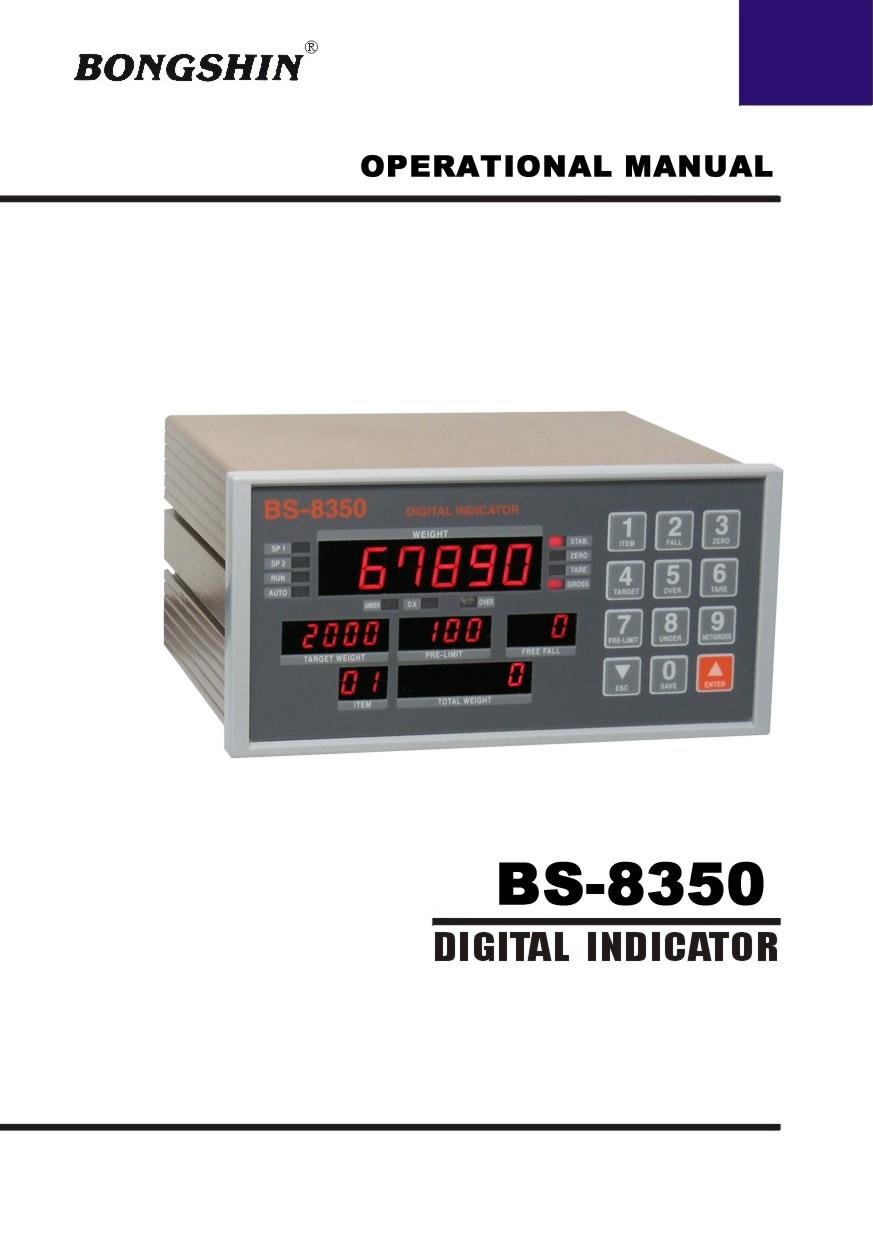
3 2 Thank you very much for your purchasing BONGSHIN Digital Weighing Indicator of BS This Instruction Manual will lead you to use BS-8350 with top reliability, High speed, high accuracy. BS-8350 is Digital Weighing Indicator amplifying the analog output from a load Cell, converting the analog signal to digital data and then displaying this data As a weight reading and is designed for flawless performance in your demanding Application of input-weighing, output-weighing, accumulating-weighing, 2step control. Also, an additional option will make Modern Industry demand equipment that both versatile And availed to easily connect to other devices Example for application : 1. PACKING EQUIPMENTS FOR MANUAL WEIGHING 2. EQUIPMENTS FOR AUTO-FILLER WEIGHING 3. EQUIPMENTS FOR OUTPUT WEIGHING 4. EQUIPMNETS FOR ACCURACY WEIGHING 5. RECORD-MANAGEMENT FOR PRODUCT WEIGHT REMARK - Specification subject to change for improvement without prior notice. - If changing, the Version No can be increased, but keeps a former version As far as possible
4 Please keep the following using conditions certainly 3 EARTH To avoid an electric error such as a noises in your production line It should be earthed before installation certainly. Specially it will be safety to divide the power of Indicator into a load cell. SAFTY CONDITIONS Don t use it closed to a explosive gas and an inflammable dust environments POWER Use the power under 110/220V 50/60HZ ±10% and divide it into the power line TEMPERTURE CONDITIONS Operating Temperature : -10 o C +40 o C ( +14 o to 104 o F ) Custody Temperature : -40 o C +80 o C ( -40 o to 176 o F ) INSTALLATION LOAD CELL - Available to use the same load cell of 6pcs ( 350Ω standard ) - A ground should be installed horizontal - Installing over 2pcs of load cell, please connect each line in parallel and Insert a variable resistor under 50Ω in EX + line and minimize a output Accuracy of load cell. It may occur a weight error by each accuracy of load cell. - It may occur a weight error in case of a temperature variation of load cell - Please weld(elect spark) at the place installed with load cell and equipments, Divide the power into a connector of load cell in inevitable case - Please connect the below construction of load cell with the above ones using The earth to the weighing part weighing a material occurring a electro sparks.
5 4 - A compact Appearance by DIN regulations ( DIN 193 x 96 Panel system ) - Easy to preset, change, confirm the weight value by the numeral key. - Improved a convenience and precision of operating with Message Function. - Can use or disuse each key function. (SETUP Reference) - Weight Memory function even in electro spark case. - Watch-Dog timer guards for self-diagnostics. - Set up to 1/20,000 display resolution - Function available to change the unit value such as g, kg, ton. ( In case of Serial Communication & Printer ) - Various specification of weight conversion speed. (Digital Filter Function) - Various option and addition for customer s satisfaction such as serial communication, RS-422, Printer, BCD Input and so on.
6 5 DC 10V ±5%, 300mA up to 8 x 350ohm load cells 0.3 μv/d Within 0.01% F.S. -1mV ~ +34mV Max. 34 mv Min. 5 mv Zero drift : ±0.2 μv/ RTI max. Span drift : 20ppm/ max. ±0.3 μv p.p or less 10 MΩ (Min.) Sigma-Delta system Approximately 200,000 counts 1/20,000 (Max.) 50 times/sec 1/20,000 7 Segment LED, 6-Digits, 14.1mm(Height) - minus signal Zero, Stable, Gross, SP1, SP2, AUTO, RUN, UNDER, OVER x1, x2, x5, x10, x20, x50, x100 0, 0.0, 0.00, 0.000,
7 6 AC 110/220V ±10%, 50/60Hz 30 VA 10 year -10 ~+40 (+14 ~ +104 ) 85% Rh Max. 193(W) x 162(D) x 96(H) 2.5 kg Serial Interface : RS-232C Serial Interface : RS-422 Parallel Interface : BCD INPUT
8 7

9 8 : : It will lamp when 1step(90%) control works : : It will lamp when 2step(100%) control works : ON when the weighing is run. : ON when the weight is stable. : ON when the current weight is 0 kg. : ON when the tare weight is stored. This Lamp will be switched to Net mode : ON when the current weight is GROSS weight. When presetting a TARE, It will be a Lamp Function. : : :

10 9 * The Key operating can be permitted or prohibited by SETUP-F10 * When pushing the key, it sounds "OK". * Each Key works either a single function or compound functions. A compound function key will be a command key when it push first and According to the command key, the fixed value works its function, The key to finish a input data is ENTER Key. ITEM Key : Usable to confirm or change the product part * Can set up the data of each product from 1 No to 50 No. - Confirmation ITEM : ITEM Key ESC Key - Changing ITEM : ITEM Key Numeral Key ENTER key FALL Key : Set Point 2(100%) weight. - Confirmation FALL : FALL Key ESC Key - Changing FALL : FALL Key Numeral Key ENTER key ZERO Key : This key returns the display to the center of ZERO when the weighing device is empty - Changing ZERO : ZERO Key ENTER key TARGET Key : Usable to confirm or change the target weight. - Confirmation TARGET : TARGET Key ESC Key - Changing TARGET : TARGET Key Numeral Key ENTER key OVER Key : OVER weight. - Confirmation OVER : OVER Key ESC Key - Changing OVER : OVER Key Numeral Key ENTER key
11 10 TARE Key 1. Set-up of TARE Key 1 Put a TARE on the weighing plate 2 TARE Key SET Key 2. Remove of TARE Key 1 Remove TARE on the weighing plate 2 Push TARE Key and push ENTER Key. PRE- LIMIT Key : Set Point 1(90%)weight. - Confirmation PRE-LIMIT : PRE-LIMIT Key ESC Key - Changing PRE-LIMIT : PRE-LIMIT Key Numeral Key ENTER key UNDER Key : UNDER weight. - Confirmation UNDER : UNDER Key ESC Key - Changing UNDER : UNDER Key Numeral Key ENTER key NET/GROSS Key After setting TARE, Net Weight converts Gross weight, or Gross weight converts Net Weight * Available to convert setting TARE only. SAVE Key When recording each sated data SAVE Key ENTER key ESC Key This have 2way to use as follows. 1) When canceling it with input the setting value 2) Change the set Point 2 value Decrease the first place value to 1.
12 11 ENTER Key This have 2way to use as follows. 1) When canceling it with input the setting value 2) Change the set Point 2 value Increases the first place value to 1.

13 12 : Power ON, OFF switch It will be safe to use it after 10minuate for a precise measurements. : Available to change AC110/220V with multiple. Before setting up, please confirm the power voltage. Please change the connect terminal of 110V/220V after opening the cover If you need to change. (It was settled with AC220V at the first) Use a stable power supply AC110/220V ±10%, 50/60Hz : please use the standard approved. FUSE AC250V, 0.5A (a glass tube with small type) : Please earth it for safe. Please connect the indicator connector with the wire of load cell according to the color. Pin no. SIGNAL 1 Load cell Input Voltage (+) EXC+ (Red) 2 Load cell output (+) SIG+ (Green) 3 Load cell output (-) SIG- (Blue) 4 Load cell Input Voltage (-) EXC- (White) 5 Shield SHIELD
14 13 EXC+ SIG+ EXC- SIG EXC+ (Red) SIG+ (Green) SIG- (Blue) EXC- (White) SHIELD The wire color of load cell according to a manufactures. 1 EXC+ 2 EXC- 3 SIG+ 4 SIG- 5 SHIELD CAS, TMI, AND RED WHITE GREEN BLUE SHIELD BLH GREEN BLACK WHITE RED YELLOW INTERFACE RED BLACK GREEN WHITE SHIELD KYOWA RED BLACK GREEN WHITE SHIELD P.T. RED BLACK GREEN WHITE SHIELD SHOWA RED BLUE WHITE BLACK SHIELD SHINKOH RED BLACK GREEN WHITE SHIELD TML RED BLACK WHITE GREEN SHIELD TFAC RED BLUE WHITE BLACK YELLOW HUNTLEIGH GREEN BLACK RED WHITE SHIELD Because wire color may be different according to a manufacture and load cell models. Please refer for the data sheet of load cell. : COM1, PAUSE, STOP, START, ZERO, PRINT This key is to control a equipment from the outside.
15 14 Please connect between COM terminal and each input terminal. Because the power of input terminal was connected with 12V voltage From the inside. * An electric current is about 10mA. * Please make the minimum time to input a data with over 50mSEC. : COM2, EMPTY, FULL, COMP, SP 1, SP 2, OVER, UNDER Connect between COM terminal and OUTPUT terminal With the earth of no electric power. Please use the output data For a signal only, don t use it for working. Max earth capacity : AC250V / 0.5A GENEANL RULES
16 - Avoid sudden Collision, vibration, temperature, water, wind - Use a stable power supply 110V/220V ± 10% 50/60Hz Set up voltage 220V 15 (Adjust the power voltage because the choice terminal of power is inside.) - Connect and power off the switch when connecting the external equipments. - Ensure to earth Indicator to equipments - Ensure to calibrate and set up it for operating. * PARTS - POWER CODE : 1EA - FUSE : 1EA (PIPE TYPE 250V 0.5A SMALL TYPE) - OPERATING MANUAL : 1EA - A Stable Connector for Option installation. FUSE : AC250V, 500mA What is Calibration?
17 16 Calibration is to adjust max weight, minimum division, decimal point displayed to Indicator To the actual weight worked by load cell. It should calibrated certainly when load cell or indicator will be changed. what is span adjustment. Span adjustment is to make the display value from "0" to max weight consistent to the actual weight. Turn on the power while pushing Key then, the display will be "SEt. CAL." Also, pushing ENTER KEY on the below right. it will be displayed with "d xx" ("xx" means 1, 2, 5, 10, 20, 50, 100) 예 ) POWER OFF CONDITIONS 1. While pushing Key Display is "SEt. CAL." 2. Pushing ENTER key Display is "d 2" "SEt. CAL." means SETUP & CALIBRATION mode S&C MODE have 6way to adjust span. each step will be advanced with ENTER key. Also, ESC key was used to return the prior conditions. F.F : ENTER key Review : ESC key
18 1 Step : Maximum Capacity Set 2 Step : Minimum Division Set 3 Step : Setting Weight in span calibration 4 Step : Zero Calibration 5 Step : Span Calibration 6 Step : END 17 - Function : Range 1~ 100 A step to set up a division value. "d" means "Division" and "xx" means a division capable of displaying. Also this value will be displayed as by each key. A step to set up a Decimal point is Function mode. So, it will be go to the next step recording the position. Key Display Description SAVE key : Increase ENTER key : SEt.CAL. condition. 1 kg (Decimal point : 0) 0.01kg (Decimal point: 2) Store and move Into next menu REF 1.The minimum division means the value of one division. REF 2. External resolution is obtained by division the min. division by the maximum capacity. Set the resolution to be within 1/30,000.
19 18 - Function : Range 1 ~ 99,999kg A step to set up max. weight. The display will appear "CAP."(Capacity) and discretion number "C " (max. 5figure) It can input the maximum weight as the end-user demands instead of discretion number. How to input is to push ENTER key after inputting discretion number. Don t excess (A division Max. weight) with over 1/20,000 If accessing over 1/20,000,it will appear "Err 01". Key Display Description ENTER key : Store and move into next menu Step 2 condition. 100 kg 10000kg REF 1. The maximum capacity means the maximum weight that scale can measure. - Function : Range 1~ 99,999kg The display discretion number "L " (span 5figure) Please input the value of standard weight for span adjustment by numeric key. How to input is to push ENTER key after inputting discretion number. This value of span standard weight must be equal to full capacity, or over 10% of full capacity. ( In case of less 1/5,000 resolution,the value of standard weight
20 must be over 10% of full capacity at least.) ( In case of over 1/5,000 resolution,the value of standard weight must be over 20% of full capacity at least.) (Notice) If span capacity is set less 10%, indicator will display error message. 19 Key Display Description ENTER key : Store and move into next menu Step kg 10000kg Setting Weight REF 1. The weight shall be within the range of 10%~100% of maximum weight. REF 2. The setting weight must be over the range of 10% of maximum weight. REF 3. The setting weight over the maximum capacity. - Function : A step to check the zero conditions of Indicator. After appearing "UnLoAd", please push ENTER key. Please do it as the zero adjustment instruction. Key Display Description ENTER key : Zero calibration and move into next menu Step 4 Unload the tray and press ENTER key Under zero calibration Zero calibration is completed. REF 1. If zero calibration is done without any error, good message is
21 20 displayed and program moves into Step 5 automatically. REF 2. If the ZERO key is pressed, only zero calibration is completed and program moves SAVE & EXIT mode. please push ESC key. - Function : Please put the span standard weight on the platform.(the weight is 10000kg at here) Press ENTER key after stable of platform. (Notice) If indicator is unmatched with load cell capacity or span standard weight, indicator will display error message. Key Display Description ENTER key : Span calibration and move into Step 5 Load the weight which was set in Step3 and press ENTER key. Under span calibration next menu Span calibration is completed. please push ESC key.(save & exit CAL mode) REF 1. If zero calibration is done without any error, good message is displayed the weight of setting weight is displayed on LED screen. Check the weight. REF 2. Check the weight of setting weight and please push ESC key and calibration is completed.
22 - Function : The "END" message is displayed in 6 step, all span adjustment is end. Press ENTER key after put down of span standard weight on the platform. The indicator will enter into user's weighing mode. 21 Key Display Description ENTER key : Step 6 Store and move into next menu REF 1. The maximum capacity means the maximum weight that scale can measure.
23 22 What is Simulation Calibration? Calibration is performed for matching the BS-8350 to a strain-gage sensor. The following two type of calibration are available for the BS Equivalent input Calibration. Calibration is performed without an actual load by entering the rated output value (mv/v) and the capacity (to be indicated) of the straingage sensor by the keys. Calibration is easily performed when no actual load is available. For example, the gain is automatically determined by entering mV/V (rated output)-100.0kg (capacity) as indicated for a load. Turn on the power while pushing Key then, the display will be "Sim. CAL." Also, pushing ENTER KEY on the below right. it will be displayed with "d xx" ("xx" means 1, 2, 5, 10, 20, 50, 100) 예 ) POWER OFF CONDITIONS 1. While pushing Key Display is "Sim. CAL." 2. Pushing ENTER key Display is "d 2" "Sim. CAL." means SETUP & CALIBRATION mode S&C MODE have 6way to adjust span. each step will be advanced with ENTER key. Also, ESC key was used to return the prior conditions. F.F : ENTER key Review : ESC key
24 1 Step : Minimum Division Set 2 Step : Maximum Capacity Set 3 Step : Rated Output value Set 4 Step : Zero Calibration 5 Step : END 23 - Function : Range 1~ 100 A step to set up a division value. "d" means "Division" and "xx" means a division capable of displaying. Also this value will be displayed as by each key. A step to set up a Decimal point is Function mode. So, it will be go to the next step recording the position. Key Display Description SAVE key : Increase ENTER key : Sim.CAL. condition. 1 kg (Decimal point : 0) 0.01kg (Decimal point: 2) Store and move Into next menu REF 1.The minimum division means the value of one division. REF 2. External resolution is obtained by division the min. division by the maximum capacity. Set the resolution to be within 1/30,000.
25 24 - Function : Range 1 ~ 99,999kg A step to set up max. weight. The display will appear discretion number "C " (max. 5figure) It can input the maximum weight as the end-user demands instead of discretion number. How to input is to push ENTER key after inputting discretion number. Don t excess (A division Max. weight) with over 1/20,000 If accessing over 1/20,000,it will appear "Err 01". Key Display Description ENTER key : Store and move into next menu Step kg 10000kg REF 1. The maximum capacity means the maximum weight that scale can measure. - Function : Range mv/v ~ mv/v The display discretion number "r2.0000" (rated output 5figure) Please input the value of standard weight for span adjustment by numeric key. How to input is to push ENTER key after inputting discretion number. Key Display Description
 rated output. Voltage(in mv/v) non-linearity, Hysteresis, input resistance, output resistance and zero balance.")
26 25 ENTER key : Store and move into next menu Step 3 1mV/V 2mV/V REF 1. A data sheet is attached to a strain-gauge sensor at the time of purchase. The data sheet provides data including: capacity load(in kg, t, etc.) rated output. Voltage(in mv/v) non-linearity, Hysteresis, input resistance, output resistance and zero balance. Enter the capacity and the rated output value required for equivalent input calibration into the BS Function : A step to check the zero conditions of Indicator. After appearing "UnLoAd", please push ENTER key. Please do it as the zero adjustment instruction. Key Display Description ENTER key : Zero calibration and move into next menu Step 4 Unload the tray and press ENTER key Under zero calibration Zero calibration is completed. REF 2. If the ZERO key is pressed, only zero calibration is completed and program moves SAVE & EXIT mode. please push ESC key.
27 26 - Function : The "END" message is displayed in 5 step, all span adjustment is end. Press ENTER key after put down of span standard weight on the platform. The indicator will enter into user's weighing mode. Key Display Description ENTER key : Step 5 Store and move into next menu REF 1. The maximum capacity means the maximum weight that scale can measure.
28 27 -- The meaning of " SET-UP " : is to choose each proper functions for matching the indicator with the appliances of field. * How to enter into set-up mode This set-up mode is required for proper weighing operation when indicator connect with other appliance. You can enter into sep-up mode by below two methods. 1) Depress key "2 (TARGET)" first and power on at the same time. At that time," F01-xx " word will be displayed on indicator. Indicator will display to " F01-xx " from above test message. 2) If you depress key "2 (TARGET)" for 3 seconds at the normal weighing mode, indicator will also display above. If you depress key "2 (TARGET)" for 3 seconds at the normal weighing mode, indicator will also display above. F 01 x x Each functional setting number Function number Abbreviation of function ---Setting method : 1) If you proceed to next function, press CLR key or, If you want to see your desirous any function number,
29 28 Press "CLR" key after input any function number by numeric key. Indicator will display function number directly from present function number. (EXAMPLE) * Present display : F01-01 Press CLR key --> "F02-00" display --> Press CLR key. --> "F03-01 display --> Continuously press CLR key --> "F04-XX" --> "F05-XX" --> "F06-XX" --> Press CLR key in streams, the next function number will be displayed. * Present display : F01-01 If you want to see function number 12, Press numeric key "1" and "2" --> Press CLR key --> "F12-XX" display 2) IF you want to change each functional setting number newly, Press ENTER key after input the functional setting number by numeric key. (EXAMPLE) If "F01-01" is changed to "F01-03", Press ENTER key --> F01-03 display --> Press ENTER key. A new function number will be memorized. (Remarks) When you want to change " S & C MODE " from Set-up mode, Please press key "2 (TARGET)" for 3 seconds at the normal weighing mode, indicator will also display above. By pressing "2 (TARGET)" for 3 seconds at the normal weighing mode, indicator will also display above.
30 29 F01 F02 F03 F04 F05 F06 F07 F08 F09 F10 F12 F12 F13 F14 F15 F16 F17 F18 F19 F20
31 30 0 No decimal point : Less vibration Adjust the set value ~ ~ according to the condition 9 9 : Much vibration how many times converted digital value read and display. 00 None automatic zero sec per 1.5 digit Auto-zero tracking will 23 ~ 2.0 sec per 1.5 digit automatically bring the display back to 0 when there are small deviations sec per 4.5 digit
32 31 00 No motion Detection Condition 03 ~ 03 : Less vibration ~ If weight change within given time is not bigger : Much vibration than the SET range, stable condition is displayed.. 00 ~ : Start, stop Relay ON 03 : 0.3 sec Relay ON ~ 99 : 9.9 sec Relay ON : 0.3sec/per 1count ~ 99 ~ 99 : 9.9sec/per 1count 0 0 : None Feedback Mode ~ 3 : 3 time average 9 9 : 9 time average 0 TARE key 1 Print key
33 32 0 Packer Mode 1 Discharging Mode bps (bit per second) bps bps bps bps 0 No data output 1 Stream mode 2 Transmit only in stable condition 3 Print key mode 4 Transmit when data is required Request signal : device ID(F13 : Device ID) In case F13 : 1, send hex value 01H in computer 0 Data Format (PC) 1 Printing Format (Korean Language) 2 Printing Format (English Language)
34 01 ~ : Device ID 1 99 : Device ID It is used the no. of indicator when system is connected. 0 g gram 1 kg kilogram 2 t ton 0 Sequence print 1 Piece print 0 Normal print 1 Sub-total Print 2 Grand-total Print Through Setting EMPTY Range. Through Setting FULL Range.
35 34 Display Meaning MAY. 5th, 2002 Display Meaning : 30 : 30 PM
36 35 Type : EIA-RS-232C Method : Full-Duplex, Asynchronous, Bi-direction Baud rate : 600, 1200, 2400, 4800, 9600bps ( Baud-Rate ) Format : 1 Data Bit : 8 (NO Parity) 2 Start/Stop : 1 bit 3 Parity Bit : None 4 Code : ASCII RXD TXD GND pin port(male) RS-232C port of BS Transmit Data 3 Receive Data 7 Signal Ground 4 Request to Send 5 Clear to Send 6 Data Set Ready 8 Carrier Detect 20 Data Terminal Ready 25 pin port(female) serial port of computer
37 36 RXD TXD GND 9 pin port(male) RS-232C port of BS Transmit Data 2 Receive Data 5 Chassis Ground 1 Carrier Detect 4 Data Terminal Ready 6 Data Set Ready 7 Request to Send 8 Clear to Send 9 pin port(female) serial port of computer Basic Program 10 OPEN "COM1:9600,N,8,1 As #1 20 IF LOC(1) = 0 THEN A$ = INPUT$(1,1) 40 PRINT A$ ; ; 50 GOTO B$=INKEY$ : IF B$ = THEN PRINT B$ ; ; 80 PRINT #1,B$; 90 GOTO 20
38 37 C Program #include <bios.h> #include <conio.h> #define COM1 0 #define DATA_READY #define TRUE 1 #define FALSE 0 #define SETTINGS 0 E3 int main(void) { int in, out, status, DONE = FALSE; bioscom(0, SETTINGS, COM1); cprintf( BIOSCOM [ESC] to exit n ); while (!DONE) { status = bioscom(3, 0, COM1); if (status & DATA_READY) if ((out = bioscom(2, 0, COM1) & 0 7F)!= 0) putch(out); if (kbhit()) { if ((in = getch()) == 1B ) DONE = TRUE; bioscom(1, in, COM1); } } return 0; }
39 38 - RS-422 is to transmit the signal by the power difference. Also, it is more safety rather other interface system for a electric noise. - Specially please use the cable with shield coax cable surely. - Recommended distance is under 1.2 km. - Both end side of a wire must be connected by the termination of 300Ω. : Same as RS-232C : Same as RS-232C 485(+) 5 485(-) 9 GND 7 9 pin port(male) RS-422 port of BS Transmit Data (+) 15 9핀포트 ( 암컷 ) 컴퓨터 Receive 직렬 Data 포트(-) 14 Transmit Data (-) 3 Receive Data (+) 1 Ground 7 Ground 4,5 Wire Connect 16,17 Wire Connect 25 pin serial port of computer. Parallel BCD input is used to change the PART to the external device. This device make it effective to weigh a various works changing the PART with a connection of Computer, PLC, Digital Switch. The inside circuit of Input & Output circuit use a photo-coupler and was isolated from the external * Recommend distance is under 10 M * BCD code makes a denary into 4figure of a binary number * In case PART 19 displayed with BCE CODE such as = OFF, 1 = ON
40 39 9P D-Type Female Connector PIN NO SIGNAL 1 COM COM BCD INPUT CIRCUIT
41 40 PRINT SHEET (SEQUENCE) ============ DATE : 2003/11/22 TIME : 12:35:07 CODE : 10 PN SN D WEIGHT 1 1 P kg 1 2 O kg 1 3 P kg 1 4 P kg 50 5 U kg 50 6 U kg 50 7 O kg 50 8 O kg ============ SUB-TOTAL DATE : 2003/11/30 TIME : 14:50:00 P.N. : 2 M.N : 8 S.T. : kg ============ GRAND-TOTAL DATE : 2003/12/01 TIME : 10:30:28 PN SN WEIGHT kg kg T.PN : 2 T.MN : 8 T.GT : kg ============ PRINT SHEET (PIECE) ============ DATE : 2003/11/22 TIME : 12:35:07 CODE : 10 PN SN D WEIGHT 1 1 P kg ============ DATE : 2003/11/22 TIME : 14:50:10 CODE : 10 PN SN D WEIGHT 1 2 O kg ============ SUB-TOTAL DATE : 2003/11/30 TIME : 14:50:00 P.N. : 1 M.N : 2 S.T. : kg ============ GRAND-TOTAL DATE : 2003/12/01 TIME : 10:30:28 PN SN WEIGHT kg kg kg PN : 2 T.MN : 38 T.GT : kg ============
42 41 0 Packer Mode 1 Discharging Mode F09-0 : Sequence 2 step Control 1(Packer Mode) F09-1 : Output 2step,Input 1step Control * Sequence 2step Control The signal of 1Step,2Step will be ON. Also if the set-up weight was the same or greater, the signal will be OFF * Output 2step,Input 1step Control Control Mode for the output only was made with 1step to input the material weighing And the 2step of output.
43 42 Sequence 2step Control ( Packer Mode ) Finished Signal & F09-0 High, Low Signal The basic operating is simple 2step control But, High and Low Signal output a signal and have a finished signal 1,2 Step Control according to the weight was changed. Each weight was setting weight and greater then, it s signal is ON, the except o f it is OFF The FALL compensation was available according to FALL set. It keeps from the first to the empty range by (1) F05-00 setting.
44 43 Sequence 2step Control ( Discharging Mode ) Finished Signal & F09-1 High, Low Signal The basic operating is simple 2step control But, High and Low Signal output a signal and have a finished signal 1,2 Step Control according to the weight was changed. Each weight was setting weight and greater then, it s signal is ON, the except o f it is OFF The FALL compensation was available according to FALL set. It keeps from the first to the empty range by (1) F05-00 setting.
45 44 ERROR CAUSE A/S Reference. Waving a weight Value. Load cell damage Insulation resistance badness of load cell. Checking for Input, Output of load cell. Resistance Value. Checking Insulation Weighing part error Resistance value of Load cell. Input resistance : about 420Ω Output resistance : about 350Ω Insulation Resistance : over100mω A. Changing a Weight value, B. Not return to ZERO Load cell damage. Disconnected to Load Cell. Checking Insulation Resistance value of Load cell. (Normal Max 100MΩ or -OL-appear) Confirm a connect of Load cell Checking a single wire Of load cell cable Weight (-) changed Load cell output (SIG+,SIG-)changed. Load cell connector Load cell damage Connection Error Load cell damage Load cell connector Appear "Ovr 1" (OVER LOAD) Excess Max weight Remove excess weight
Please keep the following using conditions certainly
 1 2 Thank you very much for your purchasing BONGSHIN Digital Weighing Indicator of BS-7200. This Instruction Manual will lead you to use BS-7200 with top reliability, High speed, high accuracy. BS-7200
Please keep the following using conditions certainly
 1 2 Thank you very much for your purchasing BONGSHIN Digital Weighing Indicator of BS-7220. This Instruction Manual will lead you to use BS-7220 with top reliability, High speed, high accuracy. BS-7220
BS-3520 Digital Indicator
 BS-3520 Digital Indicator The Better Way for Weighing & easurements Table of Contents. Introduction...3 - Trait... 3-2 Warning... 4 2. Specification...5 3. External Size...6 4. Description on Front Panel...7
igital Weighing Indicator Instruction Manual ( FS-1200C )
") D igital Weighing Indicator FINE Instruction Manual ( FS-1200C ) FINE INTER KOREA CO,. LTD 780-2, Noonsa dong, Kwangmyeong-City, Gyeonggi Do,Korea. TEL : +82 2 899 4472 FAX : +82 2 899 4479 http://www.fineweigher.co.kr
D igital Weighing Indicator FINE Instruction Manual ( FS-1200C ) FINE INTER KOREA CO,. LTD 780-2, Noonsa dong, Kwangmyeong-City, Gyeonggi Do,Korea. TEL : +82 2 899 4472 FAX : +82 2 899 4479 http://www.fineweigher.co.kr
igital Weighing Indicator
 D igital Weighing Indicator Instruction Manual ( FS-2101C ) CO,. LTD #A-106, Gwangmyeong Techno Park, 1345, Soha-Dong, Gwangmyeong-City, Gyeonggi Do, Korea. TEL : +82 2 899 4472 FAX : +82 2 899 4479 http://www.fineweigher.co.kr
INTRODUCTION. T hank you for your HB8215/HB8216 loadcell indicator purchase. The HB8215 and HB8216 are the best choice for industrial weighing
 INTRODUCTION T hank you for your HB8215/HB8216 loadcell indicator purchase. The HB8215 and HB8216 are the best choice for industrial weighing application requiring quality, performance and economy. Please
SPECIFICATIONS Digital Indicator 1. General
 SPECIFICATIS Digital Indicator 1. General The instrument is a digital indicator for the purpose of instrumentation, and suitable for the application in hopper, tank scale, and so on. 2. Specifications
Kelba (Australia) Pty Ltd. PA8101S Manual ~ TABLE OF CONTENTS
 Pty Ltd. PA8101S Manual ~ TABLE OF CONTENTS") Kelba (Australia) Pty Ltd Tel: Int 61 2 9476 4544 Web: www.kelba.com Email: Kelba@bigpond.net.au PA8101S Manual ~ TABLE OF CONTENTS Chapter 1: Introduction to the PA8101S Indicator (1) Chapter 2: Panel
Kelba (Australia) Pty Ltd Tel: Int 61 2 9476 4544 Web: www.kelba.com Email: Kelba@bigpond.net.au PA8101S Manual ~ TABLE OF CONTENTS Chapter 1: Introduction to the PA8101S Indicator (1) Chapter 2: Panel
ENGLISH ENGLISH ENGLISH ENGLISH. Installation and User Manual version 1.03 TLB4 2014/30/UE EN55022:2010 EN :2005 EN :2007
 ENGLISH ENGLISH ENGLISH ENGLISH Installation and User Manual version 1.03 TLB4 2014/30/UE EN55022:2010 EN61000-6-2:2005 EN61000-6-4:2007 SYSTEM IDENTIFICATION KEY TO SYMBOLS Below are the symbols used
1.01 TLM8 2004/108/EC EN55022 EN EN SYSTEM IDENTIFICATION
 Microlectra bv. Hermanus Boerhaavestraat 6. 3261 ME Oud-Beijerland. Netherlands. Tel 31(0)186-616290 Fax 31(0)186-610349 www.microlectra.nl info@microlectra.nl Installation and User Manual version 1.01
T1 4-Channel transmitter
 T1 4-Channel transmitter 4-20mA 0-20mA 0-10V 0-5V +/-5V +/-10V 2014/30/EU EN55022:2010 EN61000-6-2 :2005 EN61000-6-4 :2007 The Netherlands 1/48 http://www.top-sensors.com KEY TO SYMBOLS Below are the symbols
13. OP-03 RS-232C SERIAL INTERFACE
 This document hosted by: www.oldwillknottscales.com 13. OP-03 RS-232C SERIAL INTERFACE This interface allows the HC-i series to be connected with a multifunction printer or a personal computer. The OP-03
Characteristics and functioning
 Characteristics and functioning 1/36 enod4-d Characteristics and functioning NU-eNod4D-ETH-E-1014_216710-A 1 ENOD4 PRODUCT RANGE... 5 1.1 General presentation... 5 1.2 Versions and options... 5 1.2.1 Versions...
Characteristics and functioning
 Characteristics and functioning /25 ENOD4 PRODUCT RANGE:... 4. General presentation:... 4.2 enodview software tool... 4.3 Versions and options:... 4.3. Versions:...4.3.2 Options :...4.4 Dimensions:...
TLE ANALOG WEIGHT TRANSMITTER 4 20 ma, 0 20 ma, 0 10 V, 0 5 V, V, -5 5 V
 Installation and User Manual version 1.00 TLE ANALOG WEIGHT TRANSMITTER 4 20 ma, 0 20 ma, 0 10 V, 0 5 V, -10 10 V, -5 5 V 2014/30/EU EN55022:2010 EN61000-6-2:2005 EN61000-6-4:2007 SYSTEM IDENTIFICATION
General Specifications
 General Specifications GS 77J01Q08-01E Model VJQ8 Pulse to Analog Converter (Multi-function) (Isolated Single-output and Isolated Dual-output Types) General This plug-in type pulse to analog converter
AD-4826 AD G/200G/500G. For high-speed, highly accurate continuous feeding of powder and dry solids. Model predictive feeder controller
 Patent pending For high-speed, highly accurate continuous feeding of powder and dry solids AD-4826 Model predictive feeder controller AD-4826-30G/200G/500G Vibratory feeder http://www.aandd.jp Model predictive
Precise Counting Scale GC. User Manual SNOWREX INTERNATIONAL CO., LTD. SRGC
 Precise Counting Scale GC User Manual SNOWREX INTERNATIONAL CO., LTD. SRGC 20100415 Table of Contents Table of Contents...1 Specifications... 2 Basic specification... 2 Series specification(ec TYPE/OIML
The LEBOW 7554 Operator's Manual 7.2
 The LEBOW 7554 Operator's Manual 7.2 This manual covers operating version 7.2 of the LEBOW 7554. 11 February 1999 Lebow Products Inc Lebow Products Inc 1728 Maplelawn Rd Troy, MI 48084 1 (800) 803-1164
LCT100. Load Cell Tester User s Guide (v1711) Anyload Transducer Co. Ltd Website:
 Anyload Transducer Co. Ltd Website:") LCT100 Load Cell Tester User s Guide (v1711) Anyload Transducer Co. Ltd Website: www.anyload.com Email: info@anyload.com A. Basic Steps in Load Cell Testing using the LCT100: 1. Connect the load cell cable
LCT100 Load Cell Tester User s Guide (v1711) Anyload Transducer Co. Ltd Website: www.anyload.com Email: info@anyload.com A. Basic Steps in Load Cell Testing using the LCT100: 1. Connect the load cell cable
Digital Weighing Controller SI Instruction Manual. Version 3.20 (May 2011)
") Digital Weighing Controller Instruction Manual Version 3.20 (May 2011) CONTENTS DIGITAL WEIGHING INDICATOR 1. Before Installation 3 page 2. Introduction 4 page 3. Specification 5 page 4. Installation 4-1.
Digital Weighing Controller Instruction Manual Version 3.20 (May 2011) CONTENTS DIGITAL WEIGHING INDICATOR 1. Before Installation 3 page 2. Introduction 4 page 3. Specification 5 page 4. Installation 4-1.
2F. No.25, Industry E. 9 th Rd., Science-Based Industrial Park, Hsinchu, Taiwan Application Note of OGM220, AN001 V1.8
 Application Note of OGM220, AN001 V1.8 1.0 Introduction OGM220 series is a dual channels NDIR module having a digital output directly proportional to CO2 concentration. OGM220 is designed for multi-dropped
Simplified Operations for TM-3100 Series Digital Tachometer
 Simplified Operations for TM-3100 Series Digital Tachometer The TM-3100 series Digital Tachometers has the most fundamental function in rotational measurement of four standard models (rotation speed display,
This manual is subject to change without notice, at any time, to improve the product.
 WMPD4002678B This manual and Marks All safety messages are identified by the following, WARNING or CAUTION, of ANSI Z535.4 (American National Standard Institute: Product Safety Signs and Labels). The meanings
F4-08RTD 8-Channel RTD Input
 F-8RTD 8-Channel RTD 92 F8RTD 8-Channel RTD Module Specifications The F8RTD 8 Differential Channel RTD module provides several features and benefits. It provides eight RTD input channels with 16-bit resolution.
Digital Electric Micrometer. DEG2000 Instruction Manual
 Digital Electric Micrometer DEG2000 Instruction Manual Contents 1. Introduction 1 2. Main Features 1 3. Main Modes 1 4. Names and Functions of Controls and Parts 2 5. Specifications 9 6. Operation 11 6.1
Operation. Displayed channel. Measuring range. Status indication/ remote control Key lock Measuring mode/ time constant. Scale.
 Electronics & Software Type 5080A... Multichannel Laboratory This universal laboratory charge amplifier can be used for force and torque measurements with piezoelectric dynamometers or force plates. Piezoelectric
Features. Description. General Specifications. VS Series Inclinometer : Dual Axis, RS232 and Analogue Output
 Features Dual axis measurement from ±5 to ±60 High resolution and accuracy Low temperature drift, with optional temperature compensation to further improve temperature performance. RS232 output interface
DFDA5000 Reserve Manual Controller. With Servo Amplifier. Operation Instruction
 DFDA5000 Reserve Manual Controller With ervo Amplifier Operation Instruction CATALOG 1.Application..1 2.Technique Features.1 3.Ordering Number 2 4.Outline Dimension..3 5.Terminal Wiring..4 6.Key Operation
Parameter Value Unit Notes
 Features Single axis measurement from ±5 to ±60 High resolution and accuracy. Low temperature drift, with optional temperature compensation to further improve temperature performance. RS232 and RS485 output
APPENDIX APPENDIX A 1
 A 1 SPECIFICATIONS Ratings Supply voltage 100 to 240 VAC, 50/60 Hz 24 VAC, 50/60 Hz/24 VDC Operating voltage range 85 to 110% of rated supply voltage Power consumption 7VA 4VA/2.5W Sensor input Thermocouple
5700A/5720A Series II Multi-Function Calibrator
 5700A/5720A Series II Multi-Function Calibrator Operator Guide PN 601648 May 1996 1996 Fluke Corporation, Inc. All rights reserved. Printed in U.S.A. Contents What is in this Guide?... 2 Safety Summary...
Ultrasonic Multiplexer OPMUX v12.0
 Przedsiębiorstwo Badawczo-Produkcyjne OPTEL Sp. z o.o. ul. Morelowskiego 30 PL-52-429 Wrocław tel.: +48 (071) 329 68 54 fax.: +48 (071) 329 68 52 e-mail: optel@optel.pl www.optel.eu Ultrasonic Multiplexer
5700A/5720A. Operator Guide. Series II Multi-Function Calibrator
 5700A/5720A Series II Multi-Function Calibrator Operator Guide PN 3474006 May 1996, Rev. 1, 5/09 2009 Fluke Corporation. All rights reserved. Printed in USA. All product names are trademarks of their respective
8730 Electric Parameter Meter User manual
 8730 Electric Parameter Meter User manual ( Ver 2.10 ) Qingdao QINGZHI Instruments Co., Ltd. Address: 5th Floor, Building 1, Shenghe Building, No.58 Shandongtou Road, Laoshan District, Qingdao, China,
Model 4800 O P E R AT I O N M A N U A L L O A D C E L L S U M M I N G T R A N S M I T T E R
 O P E R AT I O N M A N U A L Model 4800 L O A D C E L L S U M M I N G T R A N S M I T T E R CALEX Manufacturing Company, Inc. Concord, California 94520 Ph: 925/687-4411 800/542-3355 Fax: 925/687-3333 http://www.calex.com
GE Infrastructure Sensing. Druck DPI 841/842. Frequency calibrator and Frequency loop calibrator User manual - K395
 GE Infrastructure Sensing Druck DPI 841/842 Frequency calibrator and Frequency loop calibrator User manual - K395 A1 B1 10 1 A 2 9 A 3 8 2 3 7 6 11 4 5 B1 12 A2 DPI 842 13 15 14 A3 19 18 17 16 27 20 21
Carbon Dioxide (Tiny CO2) Gas Sensor. Rev TG400 User Manual
 Gas Sensor. Rev TG400 User Manual") Carbon Dioxide (Tiny CO2) Gas Sensor Rev. 1.2 TG400 User Manual The TG400 measuring carbon dioxide (chemical formula CO2) is a NDIR (Non-Dispersive Infrared) gas sensor. As it is contactless, it has high
Carbon Dioxide (Tiny CO2) Gas Sensor Rev. 1.2 TG400 User Manual The TG400 measuring carbon dioxide (chemical formula CO2) is a NDIR (Non-Dispersive Infrared) gas sensor. As it is contactless, it has high
ICAM. Electronics & Software. Industrial Charge Amplifier for Applications in Manufacturing. Type 5073A...
 Electronics & Software ICAM Type 5073A... Industrial Charge Amplifier for Applications in Manufacturing The ICAM charge amplifier (Industrial Charge Amplifier Manufacturing) converts the piezoelectric
PalmGauss SC PGSC-5G. Instruction Manual
 PalmGauss SC PGSC-5G Instruction Manual PalmGauss SC PGSC 5G Instruction Manual Thank you very much for purchasing our products. Please, read this instruction manual in order to use our product in safety
Preset counters, electronic
 The Codix 716 / 717 can be used universally. These preset pulse, tachometers or preset timers with up to 2 presets can solve a wide variety of control and monitoring tasks in every application. With their
Series Valve Temperature Controller. Instruction Sheet
 2013/10/03 Series Valve Temperature Controller Instruction Sheet Thank you very much for choosing Delta DTV series valve temperature controller. Please read this instruction sheet before using your DTV
LCT COUNTING SCALE INSTRUCTION MANUAL
 LCT COUNTING SCALE INSTRUCTION MANUAL USER MANUAL LCT COUNTING SCALE Ⅰ. Preparation: Place the scale horizontally and keep the bubble inside the bubble level aligned with the red circle (See Fig.1). Correct
A new approach to weighing and measuring control. Loss-In-Weigher Controller BRS-1003 BORYUNG INDUSTRIAL CO.,LTD. Friends to trust!
 Loss-In-Weigher Controller BRS-1003 BORYUNG INDUSTRIAL CO.,LTD SPECIFICATIONS FEATURES Loadcell Input AI1 MODEL : BRS-1003 Flowrate measurement and control for loss-in-weight systems - Input Range : 0-40mV
For ultra-high precision measurement of current: DC, AC, pulsed..., with galvanic separation between primary and secondary. Applications.
 Current Transducer IT 605-S ULTRASTAB I PN = 600 A For ultra-high precision measurement of current: DC, AC, pulsed..., with galvanic separation between primary and secondary. Features Wide operating temperature
MINI PRINTER. Contents. Instruction Manual DESK TYPE SE7200 SD SE7200 PD SE7200 ST SE7200 PT. Chapter 1. Pre-face. Chapter 2.
 Instruction Manual SE 7200 DESK TYPE SD PD ST PT Chapter 1. Pre-face 1-1. Feature 1-2. Usage Chapter 2. Introduction 2-1. Specification 2-2. Control Panel Function 2-3. Self Test Mode 2-4. Hex Decimal
96M0374. Instruction Manual. Analog Sensor Controller. RD Series
 Instruction Manual Analog Sensor Controller RD Series 96M0374 Safety precautions This manual describes how to install the RD Series as well as its operating procedures and precautions. Please read this
Model FLSC-C3-XX. DC Powered Microprocessor Controlled Transmitter
 Model FLSC-C3-XX DC Powered Microprocessor Controlled Transmitter CONTENTS. Introduction----------------------------------------------------------------- 2 2. Specifications ---------------------------------------------------------------
User s instructions. Page 1 sur 20 AXD-C / AAD-C / DVX-C / DVS-C : User s instructions B
 User s instructions Page 1 sur 20 : User s instructions 195752-B Document revisions version date description A 13/01 - Creation B 04/17 - Add DVX-C and DVS-C Page 2 sur 20 : User s instructions 195752-B
ROTRONIC HygroClip Digital Input / Output
 ROTRONIC HygroClip Digital Input / Output OEM customers that use the HygroClip have the choice of using either the analog humidity and temperature output signals or the digital signal input / output (DIO).
Additel 875 Series Dry Well Calibrators
 Additel 875 Series Dry Well Calibrators Three models ranging from -40 to 660 Portable, rugged, and quick to temperature Metrology-level performance in stability, uniformity, accuracy and loading effect
Connection. Input EEx ia IIC. Sense. Fine tuning adjustment. Fine tuning amplifying. Amplifying. Adjustment. Output. Composition
 Converter Connection 1-channel EEx ia IIC for 4-wire and 6-wire bridges Analogue output 0/4 ma... 20 ma or 4mA...-12mA Full bridge load cells and strain gauges circuit for resistance bridges up to 17 Ω
Select datum Page backward in. parameter list
 HEIDENHAIN Working with the measured value display unit ND Actual value and input display (7-segment LED, 9 decades and sign) Select datum Page backward in parameter list Confirm entry value Set display
VersaPoint I/O Module
 GFK-2012A March 2010 Module provides two-input channels for measuring signals from standard thermocouples. It supports thirteen different thermocouples types. In addition, it accepts linear voltage inputs
DIGEM f 96 x 48 EK. Applications. Description
 3-349-002-03 1/7.98 Front panel dimensions: 96 x 48 mm LED display: red or green, 14 mm high Max. display range: 19 999 to + 32 765 Modular connectors for flexible use Simple adjustments at front panel
Model 6517B Electrometer / High Resistance Meter Specifications
 VOLTS Accuracy (1 Year) 1 / C 2V 10µV 0.025+4 0.003+2 20V 100µV 0.025+3 0.002+1 200V 1mV 0.06+3 0.002+1 NMRR: 2V and 20V range > 60dB, 200V range > 55dB. 50Hz or 60Hz 2 CMRR: >120dB at DC, 50Hz or 60Hz.
6/12/24 Dot Printing Model Smart Recorder SRF206/212/224
 No. CP-SS-E // Dot Printing Model Smart Recorder SRF0// The Smart Recorder SRF 0// Dot Printing Model accepts DC voltage, thermocouple, resistance temperature detector (RTD), communications and ON/OFF
IP 251 Universal Signal Converter SSI parallel RS232 parallel SSI RS232
 control motion interface ELEKTRO-TRADING sp. z o.o Tel. +48 (0-32) 734-55-72 Tel/Fax +48 (0-32) 734-55-70 E-Mail et@elektro-trading.com.pl http://www.elektro-trading.com.pl IP 251 Universal Signal Converter
control & display PROGRAMMABLE SENSOR CONTROLLER COMPLETE VERSATILITY OF SENSOR MANAGEMENT & DATA COMMUNICATIONS
 S E N S O R S PROGRAMMABLE SENSOR CONTROLLER TX9044 COMPLETE VERSATILITY OF SENSOR MANAGEMENT & DATA COMMUNICATIONS Analogue sensors, temperature devices, frequency inputs and digital sensors direct fingertip
Charge Meter. Electronics & Software. Universally Applicable for Piezoelectric Measuring Technology. Type 5015A...
 Electronics & Software Charge Meter Type 5015A... Universally Applicable for Piezoelectric Measuring Technology This instrument can be used wherever mechanical quantities are measured with piezoelectric
MODEL: DAST-20. Telemetering System
 MODEL: DAST-0 Telemetering System TELEMETERING SYSTEM Functions & Features Small-scale telemetering system Lightning arrester protecting telephone circuit standard Approved of Technical Requirements Compliance
ADAM 4000/4100 Series
 ADAM 4000/4100 Series Common Dimensions Communication RS-485 (2-wire) to host Speeds: 1200, 2400, 4800, 9600, 19200, 38400, 57600, 115200 bps (ADAM-4080, ADAM-4080D only support up to 38400 bps) Max. communication
ST-10 Expert. Horn Analyzer. for serial and parallel resonance Resonators. Bär. Operator Manual.
 Bär Elektronik Hauptstrasse 39 CH-8594 Güttingen 0041 71 695 12 83 Horn Analyzer ST-10 Expert for serial and parallel resonance Resonators Operator Manual Version 2.5 www.baer-elektronik.ch ndice 1.0 Controls
PROCESS & TEMPERATURE CONTROLLERS
 PROCESS & TEMPERATURE CONTROLLERS NOVA PD54 Series Thermocouple, RTD, & Process Inputs High Accuracy Auto-Tuning PID Heating & Cooling Models Universal Power Supply 1-24 VAC Up to 3 Relays & 2 Analog Outputs
SOLAR-360 : 360 Inclinometer, RS232 or RS485 Output
 Features Single axis measurement, range ±180 High resolution and accuracy Low temperature drift, with optional temperature compensation to further improve temperature performance. RS232 or multi-drop RS485
Easy-to-read in either English, French, or German; 20-digit, 2-line display; 6-channel simultaneous display possible
 PHA & PHC STRIP CHART RECORDERS WITH BRILLIANT SIX-COLOR PRINTING Why use dot-matrix or fiber-tip pen printing when Fuji Electric s patented, cutting-edge recording technology offers an affordable inkjet
SHIMADEN DIGITAL INDICATORS
 Shimaden, Temperature and Humidity Control Specialists C %RH Series SD16A & SHIMADEN DIGITAL INDICATORS approved,ul applied BASIC FEATURES compliance DIN Size 48 x 96 mm ±.3% High Accuracy Indication Large
Fuji Electric Instruments Co.,Ltd
 Instruction Manual for FD5000 Series 1/12! 1. Before Using the Product Thank you for purchasing the FD5000 series. This manual should be passed on to the person who operates the product. Examine the product
Section 1, General information Introduction... 3 Description... 3 Specifications... 4 Wiring connections... 5
 LIST OF CONTENTS Section 1, General information Introduction... 3 Description... 3 Specifications... 4 Wiring connections... 5 Section 2, Calibration Calculations... 7 Calibration Procedure... 8 Section
DIGITAL INDICATOR CC-Link Interface CSD Instruction Manual
 DIGITAL INDICATOR CC-Link Interface CSD-903-73 Instruction Manual EN294-1499D 1 2 Introduction Thank you very much for your purchasing Minebea s Digital Indicator, model CSD-903-73. This instruction manual
Refer to manual. Failure to read message could result in personal injury or serious damage to the equipment or both.
 CERAVAC Transmitter CTR 100 N Short form manual 300544675_002_C0 Part numbers: 230 300V02 230 310V02 230 301V02 230 311V02 230 302V02 230 312V02 230 303V02 230 313V02 230 304V02 230 314V02 230 305V02 230
MODEL: DLS. Telemetering System
 POW RUN SA SA RT RU MODEL: DLS Telemetering System TELEMETERING UNIT Functions & Features Interfacing remote I/O devices with a modem for a telemetering system Process I/O (.0) [] POWER INPUT AC Power
Universally Applicable for Piezoelectric Measuring Technology. Technical Data. Charge Input. Instant value. Extreme values ors statistic measurements
 Electronics & Software Charge Meter Universally Applicable for Piezoelectric Measuring Technology Type 5015A... This instrument can be used wherever mechanical quantities are measured with piezoelectric
Confirm entry value Set display to value from Actual value and input display Select datum P79 (P80!) (7-segment LED,
 (7-segment LED,") HEIDENHAIN Working with the measured value display unit ND 261 Confirm entry value Set display to value from Actual value and input display Select datum P79 (P80!) (7-segment LED, Page backward in 9 decades
HEIDENHAIN Working with the measured value display unit ND 261 Confirm entry value Set display to value from Actual value and input display Select datum P79 (P80!) (7-segment LED, Page backward in 9 decades
WRM-10 TM TRANSFORMER WINDING RESISTANCE METER
 WRM-10 TM TRANSFORMER WINDING RESISTANCE METER USER S MANUAL Vanguard Instruments Company, Inc. 1520 S. Hellman Ave. Ontario, California 91761, USA TEL: (909) 923-9390 FAX: (909) 923-9391 June 2009 Revision
Analog Module D1-15P User Manual
 D1-15P Manual Analog Module D1-15P User Manual Sielco Elettronica Srl Edison Street 209 20019 Settimo Milanese (MI) - Italy http://www.sielcoelettronica.com info @ sielcoelettronica.com Tel 02 48916252
This Errata Sheet contains corrections or changes made after the publication of this manual.
 Errata Sheet This Errata Sheet contains corrections or changes made after the publication of this manual. Product Family: DL4 Date: September 12, 218 Manual Number D4-ANLG-M Revision and Date th Ed., Rev.
SR25. SHIMADEN DIGITAL CONTROLLER Shimaden, Temperature and Humidity Control Specialists MICROPROCESSOR-BASED AUOT-TUNING PID CONTROLLER
 SHIMADEN DIGITAL CONTROLLER Shimaden, Temperature and Humidity Control Specialists SERIES SR25 MICROPROCESSOR-BASED AUOT-TUNING PID CONTROLLER High Accuracy ±0.1% High Sampling Cycle 0.1 sec. Auto-Tuning
BATCHMATE 1500 Batch Control Computer Technical Bulletin
 TS-5(C) BATCHMATE 5 Batch Control Computer Technical Bulletin DESCRIPTION The BATCHMATE features an 8 digit.55-in. alphanumeric LED display. The pulse input model will accept up to 2, pulses per second
MAGTROL. LMU Series Load Monitoring Units. LMU Data Sheet. Description. Features
 MAGTROL Data Sheet Series Load Monitoring Units Features For use with full-bridge strain gauge transducers (sensitivity 0.5 to 4 mv/v) Voltage input for load summation or for individual use (without sensor)
Select datum Page backward in parameter list
 HEIDENHAIN Working with the measured value display unit ND Actual value and input display (7-segment LED, 9 decades and sign) Select datum Page backward in parameter list Confirm entry value Set display
SMR5000F. User Manual. Smart Radio Data Repeater. Web Site: P.N.: Book 092
 SMR5000F Smart Radio Data Repeater User Manual ISRAEL Office: Email: info@kpsystems.com PO Box 42, Tefen Industrial Park, Tefen 24959 Tel: 972-4-987-3066 / Fax: 972-4-987-3692 USA Office: KP ELECTRONICS,
AIO and DIO PFXLM4B01DAK:Sink Output Type PFXLM401DAC:Source Output Type Virtual Resolution (pixels)
") Model:PFXLM4B01DDK PFXLM4B01DDC PFXLM4B01DAK PFXLM4B01DAC LT4000M Rear module Model Name Indication PFXLM4B01 D * * (1) (2) (3) (4) Notice to our valued customers who use LT4000M series (analog model)
Model:PFXLM4B01DDK PFXLM4B01DDC PFXLM4B01DAK PFXLM4B01DAC LT4000M Rear module Model Name Indication PFXLM4B01 D * * (1) (2) (3) (4) Notice to our valued customers who use LT4000M series (analog model)
Single Channel Loop Detector
 Single Channel Loop Detector Model LD120T Series The LD120T is a series of single channel inductive loop detectors. The use of microprocessor and surface mount technology enables a large number of functions
Data Acquisition Modules/ Distributed IO Modules
 User Manual Data Acquisition Modules/ Distributed IO Modules Future Design Controls, Inc. 7524 West 98 th Place / P.O. Box 1196 Bridgeview, IL 60455 888.751.5444 - Office: 888.307.8014 - Fax 866.342.5332
 1 Model 3153 Automatic Insulation Voltage Withstand Testing Voltage Control from a PC Full Remote Control All test parameters can be controlled by RS-232C or GP-IB, including test voltage, cut-off current,
Voltage regulator TAPCON 240
 Voltage regulator TAPCON 240 Supplement 2398402/00 Protocol description for IEC 60870-5-103 All rights reserved by Maschinenfabrik Reinhausen Copying and distribution of this document and utilization and
F340A DIGITAL INDICATOR
 F340A DIGITAL INDICATOR OPERATION MANUAL 4. JUN. 2004 Rev. 1.34 Introduction Introduction We appreciate your kind purchase of F340A Digital Indicator. To take full advantage of high performance of F340A,
DPF-MAC Auto power factor controller
 Digital Electric& Electronics System DPF-MAC Auto power factor controller MULTI POWER FACTOR AUTOMATIC MULTI POWER FACTOR AUTOMATIC Introduction DPF-MAC increases usage efficiency by controlling the power
ma/bcd Converter Model MFC-201 ma/bcd The MFC-201 ma/bcd Converter is a device designed to convert a DC current signal into BCD (8421) signals.
 signals.") 1 Definition ma/bcd Converter Model MFC-201 ma/bcd The MFC-201 ma/bcd Converter is a device designed to convert a DC current signal into BCD (8421) signals. 2 Operating Principle An electronic circuit
1 Definition ma/bcd Converter Model MFC-201 ma/bcd The MFC-201 ma/bcd Converter is a device designed to convert a DC current signal into BCD (8421) signals. 2 Operating Principle An electronic circuit
DIGITAL THERMOMETER Digital Thermometer FEATURES INDEX RECORDERS
 Digital Thermometer 23 88 350 mm 3 kg (8-5/8 3-/2 3-3/4" 6.6 lbs) The Digital Thermometer has 6 ranges of temperature sensors and measuring functions of DC V and Ω. YOKOGAWA-original A/D converter (feedback
Electric Motor Actuator with a built in Microcomputer
 Electric Motor Actuator with a built in Microcomputer The New MICOM ELMY offers highly accurate controllability, and its various functions are easily set via communication with a personal computer. Controller
TRANSMITTER CSA-522B. Instruction Manual EN E
 TRANSMITTER CSA-522B Instruction Manual EN294-1348-E II Forward Thank you very much for purchasing the transmitter, model CSA-522B. This manual explains installation procedures and connecting method and
Ethernet-Based Temperature, Voltage and Strain Measurement Modules
 Ethernet-Based Temperature, Voltage and Strain Measurement Modules OMB-NET6000 Series OMB-NET6220 shown smaller than actual size. U 12 Analog Inputs U 8 Digital I/O U Simultaneous Sampling U Multiple Trigger
PC-805 Parts Counter User s Manual
 PC-805 Parts Counter User s Manual EUROPEAN COUNTRIES WARNING This is a Class A product. In a domestic environment this product may cause radio interference in which the user may be required to take adequate
DC1010/DC1020/DC1030/DC1040
 05/0 0-10-10-0-EN Page 1 of DC1010/DC1020/DC100/DC1040 DIGITAL CONTROLLERS Specification Overview The DC1000 Series are microprocessorbased controllers designed with a high degree of functionality and
Electric Motor Actuator with a built in Microcomputer
 Electric Motor with a built in Microcomputer The New MICOM ELMY offers highly accurate controllability, and its various functions are easily set via communication with a personal computer. Controller features
Load cells connection. Supply and relay connection. AC digital input connection. DC digital input connection. -20 o C ~ 60 o C. Operating Temperature
 Operating Voltage Power Consumption Operating Temperature Load Cell Excitation Relay Outputs Digital Inputs (AC) A/D Sampling speed Display Analog Input range Input impedance Size 230VAC,50Hz Approx. 3VA
1000TR. Instructions
 1000TR ph Instructions CONTENTS 1. INTRODUCTION... 2 1.1 COMMON INTRODUCTION... 2 1.2 PARTS & ACCESSORIES... 2 2. INSTALLATION... 3 2.1 CASING... 3 2.2 MOUNTING... 3 2.3 ELECTRICAL INSTALLATION... 3 2.3.1
9320 Manual Portable Battery Powered Indicator
 9320 Manual Portable Battery Powered Indicator Interface, Inc. 7401 E. Butherus Dr. Scottsdale, AZ 85260 800-947-5598 480-948-1924 (fax) www.interfaceforce.com CONTENTS INTRODUCTION...2 USER OPERATION...2