1000TR. Instructions
|
|
|
- Coleen Lynch
- 5 years ago
- Views:
Transcription
1 1000TR ph Instructions
2 CONTENTS 1. INTRODUCTION COMMON INTRODUCTION PARTS & ACCESSORIES INSTALLATION CASING MOUNTING ELECTRICAL INSTALLATION Connection of the power supply Connection of the electrode Connection of a temperature probe ( RTD Pt100 ) Connection of a recorder CHECK THE CONNECTIONS FUNCTIONS COMMON FUNCTIONS MEASURE CAL CAL CAL TEMP OUTPUT ALARM KEY FUNCTIONS PARAMETER SETTINGS DEFAULT SETTINGS PARAMETER SETTINGS Setting of the temperature compensation Set the output signal CALIBRATION OPERATION CHANGING THE PARAMETER SETTINGS Change the temperature compensation Change the output range MAINTENANCE HARDWARE CHECK PRE-CALIBRATION RESET OF DEFAULT SETTINGS TROUBLE SHOOTING SPECIFICATIONS
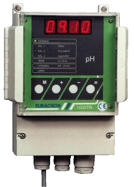
3 1. INTRODUCTION 1.1 COMMON INTRODUCTION 1000TR is a new CE-approved series of transmitters from Elmacron AB. In the series, there are instruments for ph, Redox%, Redox mv and temperature measurement. 1000TR is easy to program, calibrate and use. The layout on the instrument is clear; a large display with four LED-segments, diode indication for the menu and four large function keys. All settings are made through the function keys on the front panel. When connecting an electrode to 1000TR-pH the display shows the actual ph-value in the solution measured. Manual / Automatic temperature compensation is built-in to give the highest possible accuracy over the whole range. 1000TR-pH is provided with an isolated output 0/4-20 ma, proportional to the ph-value, for connection to, for example, a computer, printer or other recording equipment. When measuring is interrupted, the output stays frozen at the last measured value. 1.2 PARTS & ACCESSORIES 1000TR is delivered without connection cables and electrodes. Article Function Code number Power supply cord, standard Power supply 20-R Low noise coax cable with BNC-connection Connection of electrode/probe 60-T810-0xx* ( xx* = 01, 02, 03, 05, 07 or 10 meter ) Pt100-probe, glass. Type T2V12 Automatic temperature compensation 60-K ph-buffer 7.00, 500 ml Calibration of ph-electrode 90-T ph-buffer 4.00, 500 ml Calibration of ph-electrode 90-T ph-buffer 10.00, 500 ml Calibration of ph-electrode 90-T
4 2. INSTALLATION 2.1 CASING The casing is made of die-cast polystyrol with a transparent front cover that is closed with a snaplock. The connection terminals are located in a separate partition at the lower part of the transmitter. At the bottom of the instrument there are four cable glands ( two 15,2 and two 18,6 ) for the electrical connections. The protection class is IP MOUNTING The instrument is designed for wall mounting. Be sure that the instrument is mounted at a nonvibrating place. 1000TR is mounted vertically with two fastening screws ( 7) through the mounting brackets on the instrument. 2.3 ELECTRICAL INSTALLATION It is recommended that each instrument is provided with a separate power switch. The electrode coax cable must be protected by a screen and may not be installed near power cables. Avoid extension of cables. The connection terminals are located in a separate space at the lower part of the transmitter
5 2.3.1 Connection of the power supply Connect the power supply to terminal 1 (earth), terminal 2 (zero) and terminal 3 (live) Connection of the electrode Electrode cabling is a critical part of the whole system. Use a low noise coax cable between the electrode and the input terminal on the controller. Low noise cables has, in general, a black semi-conductive sheath between the centrewire insulation and the shield. Remove this sheath. Keep the cable away from power wires. Max recommended length of cable is 10 meters. Connect the shield ( reference ) of the coax cable to terminal 4 ( EL - ). Connect the centre ( glass electrode ) of the coax cable to terminal 5 ( EL + ) Connection of a temperature probe ( RTD Pt100 ) When automatic temperature compensation is configured, a Pt100-probe is connected to terminal 6, 7, 8 and 9 ( 1A, 1B, 1C and 1D ) Connection of 4-wire Pt Connection of 2-wire Pt100 The temperature sensor has to be installed in the same solution being measured, close to the electrode either in-line or in the tank. A pre-set calibration has to be done when installing a new Pt100- sensor ( see chapter 5.2 ). When manual temperature compensation is configured a 107 Ω-resistor is connected to the temperature input and a jumper is set between terminals as shown in the figure below Connection of a recorder Connect the recorder to terminal 10 ( REC + ) and terminal 11 ( REC - ). 2.4 CHECK THE CONNECTIONS Before the power supply is turned on; check that the connections are mechanical and electrical correct
6 3. FUNCTIONS 3.1 COMMON FUNCTIONS All settings are made through the function keys on the front panel. The keys + and are accelerating in three steps when they are kept pressed. Chosen function is indicated by a green diode in the menu, at alarm a red diode is activated at the same time as the diode at the actual function activates. When pressing M you step down in the menu. When calibration or setting mode is entered the output signal stays "frozen" at the latest value, until = is pressed. 3.2 MEASURE CAL. 1 CAL. 2 CAL. 3 TEMP. Offset High-buffer Low-buffer Aut./Man. 0/4-20 ma OUTPUT ALARM MEASURE When power supply is connected the measuring starts CAL. 1 Calibration point 1. Pre-set value: ph 7.00, other values can be chosen in the calibration mode CAL. 2 Calibration point 2. Pre-set value: ph 10.00, other values > ph 7.00 can be chosen in the calibration mode CAL. 3 Calibration point 3. Pre-set value: ph 4.00, other values < ph 7.00 can be chosen in the calibration mode TEMP. The instrument is provided with a choice between automatic and manual temperature compensation. The values shown when automatic temperature compensation is activated, the value is corresponding to the temperature 20 C. In manual compensation mode, the temperature is set by the operator OUTPUT Can be set to 0-20 ma or 4-20 ma. The function is scaleable
7 3.2.7 ALARM When an error occurs in the measuring mode, the alarm diode activates at the same time as the error code is shown on the display. At serious errors, the error code is flashing on the display. 3.3 KEY FUNCTIONS KEY FUNCTION 1 ( at parameter setting mode ) FUNCTION 2 ( in measuring mode ) Steps down the menu Accelerating key. Increase the value in setting mode. Used when making a choice according to the display. Interrupt measuring together with Accelerating key. Decrease the value in setting mode. Interrupt measuring together with Confirm performed settings and choices. Starts measuring
8 4. PARAMETER SETTINGS 4.1 DEFAULT SETTINGS When delivered, 1000TR have the following default settings. Output 0-20 ma Temperature compensation Manual, 20 C Offset ph = 7.00 Low-buffer ph = 4.00 High-buffer ph = Slope 100% ( 20 ) 4.2 PARAMETER SETTINGS All settings has to be confirmed with = to be saved. To leave the setting mode without saving the settings: press M. Before starting up the transmitter the following parameters has to be set: Temperature compensation and output range. Turn the power on Setting of the temperature compensation 4.2.1a) Manual temperature compensation For automatic temperature compensation, see b). 1. Interrupt the measuring by pressing + and at the same time until the measuring is interrupted and the diode at CAL.1 is activated. 2. Press M until the diode at TEMP. is activated. At the display: In--. Press = to confirm. 3. Set the correct temperature with + and -. Press = to confirm. The diode at OUTPUT activates and the display shows b) Automatic temperature compensation In automatic temperature compensation a Pt100 sensor has to be installed ( see chapter 2.3 for connection ). NOTE! Save the 107Ω resistor. A pre-calibration according to 5.2 has to be performed when a new Pt100 sensor is installed. 1. Interrupt the measuring by pressing + and at the same time until the measuring is interrupted and the diode at CAL.1 is activated. 2. Press M until the diode at TEMP. is activated. At the display: In Press + until the display shows Au--. Press = to confirm. The diode at OUTPUT activates and the display shows Set the output signal 1. Choose between 0-20 and 4-20 ma with Press = to confirm. 3. The display shows SPAn. Press = to confirm. 4. The display shows Set the ph-value corresponding to 0 (alt. 4) ma. 5. Press = to confirm. The display shows
9 6. Set the ph-value corresponding to 20 ma. Press = to confirm. 7. The diode at MEASURE is activated and the display shows Hold. 8. Press = to start the measurement. NOTE! The ph-values have to be set so that the 0/4 ma-level is corresponding to a lower value than the 20 ma value. In other cases the output signal stays at 0 ma. 4.3 CALIBRATION When delivered the transmitter is calibrated according to standard: offset ( zero point ) at ph 7.00, and slope 100% at 20 C. The transmitter should be calibrated on a regular basis according to ph, to reach a high security in the measurement. Calibration can be performed at 1, 2 or 3 ( recommended ) calibration points. The transmitter is preset for calibration at ph 7.00 ( offset ), ph 4.00 (low buffer) and ph (high buffer), other values can be chosen. If calibration at two points is desired, it is recommended that the calibration points are chosen at the "zero-point" and at a point close to the expected ph. During the calibration, the latest output signal stays "frozen". When a new electrode is installed or at the first start-up of the instrument, we advise you to do as follows: Check that the electrode glass membrane is stored wet. If the protective cap is empty and the electrode is dry, immerse the electrode in a buffer solution or tap water ( do not use destilled water ) for three hours before calibration ( and using ). If the transmitter is set for manual temperature compensation, the temperature of the buffer solution has to be set. ( see chapter ). If the transmitter is set for automatic temperature compensation, the Pt100-sensor has to be immersed in the buffer solution together with the electrode. 1. Interrupt the measuring by pressing + and at the same time. 2. The instrument automatically steps down to CAL. 1 ( calibration point 1). Pre-set zeropoint is at ph 7.00, if another offset value is desired it can be set with + and Rinse the electrode membrane carefully with destilled water. 4. Put the electrode in buffer 1. Press = to start. Wait until the value at the display has stabilised. Use + and to set the correct value. Press = to save the calibration. If the measured value differs more than ± 1.5 ph-units* from the pre-set buffer value, calibration can not be performed. When pressing = a message is shown, ( see chapter 6 ). Locate and correct the error and try again. Press M to interrupt the calibration. 5. The instrument automatically steps to CAL. 2 (calibration point 2). At calibration point 2, the instrument is calibrated at a high-buffer value ( ph > 7 ). If no calibration at point 2 is desired, the point can be ignored by pressing M until the diode at CAL.3 is activated. 6. The pre-set value on buffer 2 is ph 10.00, if another offset value is desired it can be set with + and Rinse the electrode membrane carefully with destilled water
10 8. Put the electrode in buffer 2. Press = to start. Wait until the value at the display has stabilised. Use + and to set the correct value. Press = to save the calibration. If the phslope differs more than +10%, -20%* the calibration is not accepted and the value can not be adjusted. If the ph-slope differs more than +10%, -20%* the alarm diode is activated and the calibration can not be done, when pressing = an error message is shown, (see chapter 6). Accept the error by pressing =. Locate and correct the error and try again. Press M to interrupt the calibration. 9. The instrument automatically steps to CAL. 3 (calibration point 3). At calibration point 3 the instrument is calibrated at a low-buffer value ( ph < 7 ). If no calibration at point 3 is desired, the point can be ignored by pressing M. 10. The pre-set value on buffer 3 is ph 4.00, if another offset value is desired it can be set with + and Rinse the electrode membrane carefully with destilled water. 12. Put the electrode in buffer 3. Press = to start. Wait until the value at the display has stabilised. Use + and to set the correct value. Press = to save the calibration. If the phslope differs more than +10%, -20%* the calibration is not accepted and the value can not be adjusted. If the ph-slope differs more than +10%, -20%* the alarm diode is activated and the calibration can not be done, when pressing = an error message is shown, (see chapter 6). Accept the error by pressing =. Locate and correct the error and try again. Press M to interrupt the calibration. 13. Step to MEASURE with M. 14. Rinse the electrode membrane carefully with destilled water. 15. Do not forget to reset to the process temperature when manual temperature compensation is chosen. 16. The instrument is now ready for measuring. Press M to start. The accepted range is calculated in relation to the distance from the offset value. Example: Offset ( zero ) ph 7.00 Calibration point 1 ph Calibration point 2 ph 4.00 Accepted ph-slope is +10%, -20% from ideal slope. The deviation is calculated according to: ph = 3, which gives max deviation = +10 % of 3 = 0,3 ph-units, -20 % of 3 = -0,6 ph-units. ph 4.00 = -3, which gives max deviation = +10 % of -3 = -0,3 ph-units, -20 % of -3 = 0,6 ph-units. The accepted intervals in the example: calibration point 1 = ph 9,4 - ph 10,3 calibration point 2 = ph 3,7 - ph 4,6 Accepted limits for the offset value is ph 5,5 - ph 8,5-9 -
11 ph ,5 ph ,3 0, ,5 0,6 0, OPERATION Measuring is started when the power supply is turned on. After an interruption off the measuring it can be restarted by pressing = when the MEASURE diode is activated. The display shows the actual ph-value in the solution measured at the same time as the corresponding ma-signal is sent to the output. During the operation, the diode at MEASURE is activated. 4.5 CHANGING THE PARAMETER SETTINGS All settings has to be confirmed with = to be saved. To leave the setting mode without saving the settings: press M Change the temperature compensation Manual temperature compensation 1. When manual temperature compensation is configured a 107 Ω-resistor is connected to the temperature input and a jumper is set between terminals as shown in figure below. 2. Interrupt the measuring mode by pressing + and at the same time until the measurement is interrupted and the diode at CAL.1 is activated. 3. Press M until the diode at TEMP. is activated. 4. Press + until the display shows In-- Press = to confirm. 5. Set the correct temperature with + and -. Press = to confirm. The diode at OUTPUT is activated and the display shows Step to MEASURE with M. Hold is shown on display, start measuring by pressing =. Automatic temperature compensation
12 1. Connect a Pt100-sensor to the instrument ( see chapter 2.3 for connection instructions). Make a pre-calibration according to chapter Interrupt the measuring mode by pressing + and at the same time until the measurement is interrupted and the diode at CAL.1 is activated. 3. Press M until the diode at TEMP. is activated. 4. Press + until the display shows Au--. Press = to confirm. 5. The diode at OUTPUT is activated and the display shows Step to MEASURE with M. Hold is shown on display, start measuring by pressing = Change the output range 1. Interrupt the measuring mode by pressing + and at the same time until the measurement is interrupted and the diode at CAL.1 is activated. 2. Step to OUTPUT with M. 3. Choose between 0-20 and 4-20 ma with Press = to confirm. 5. The display shows SPAn. Press = to confirm. 6. The display shows Set the ph-value corresponding to 0 (alt. 4) ma. 7. Press = to confirm. The display shows Set the ph-value corresponding to 20 ma. Press = to confirm. 9. The diode at MEASURE is activated and the display shows Hold. 10. Press = to start the measurement. NOTE! The ph-values have to be set so that the 0/4 ma-level is corresponding to a lower value than the 20 ma value. In other cases the output signal stays at 0 ma
13 5. MAINTENANCE 5.1 HARDWARE CHECK A check of the hardware is necessary only if you suspect that there is something wrong with your transmitter. 1. Disconnect the power supply. 2. Short-circuit the electrode input. 3. Connect a ma-meter to the REC-output. 4. Press M and connect the power supply, keep M pressed during 5 seconds until the four upper diodes are activated. 5. The transmitter performs a self-test according to table Hardware check CH01 Test of LED on display All 4 LED-segments are activated CH02 Test of function keys Press the keys one by one and the corresponding sign is shown on the display CH03 Test of output signal Press = is shown on the display at the same time as the corresponding signal is sent to the output. Press = is shown on the display at the same time as the corresponding signal is sent to the output. Press = CH04 test of diodes All the menu diodes are activated The version number is shown, then the instrument starts to measure. 5.2 PRE-CALIBRATION The transmitter is always pre-calibrated when delivered. Pre-calibration is only necessary when the instrument has been shut of for a longer period or when a new Pt100-sensor is connected. 1. Turn the power off. Short-circuit the electrode input. Connect a 100 Ω-resistor to the Pt100-input terminal clamps. Make a connection between the terminals according to the figure below or, when a new Pt100-sensor is connected, put the sensor in icy water ( 0 C )
14 2. Press and turn on the power supply. Keep the key pressed until the display shows CAL1. (10 seconds). Every second diode is activated. CAL1. 3. Press = to continue. 4. On the display E0.00 during 5 s. 5. On the display CAL2. 6. On the display P0.0 during 5 s. 7. On the display CAL3. 8. On the display 0.01A CAL2.. Press = to continue. CAL3. Press = to continue. 0.01A. Press + or - to receive 10.0 ma on the ma-instrument. NOTE! You have to press + or - repeatedly to get a change in the signal, 9. Press = to continue. The display shows the version number during 5 sec. 10. The instrument returns to measuring mode, the measuring starts automatically. 11. If manual temperature compensation is chosen the 100 Ω-resistor is replaced with a 107 Ω-resistor. 5.3 RESET OF DEFAULT SETTINGS The settings are reset according to chapter Turn off the power supply. 2. Press + and turn on the power supply. Keep the key pressed until the display shows C l r O (10 seconds). The four lower diodes are activated. 3. Press = to continue. 4. The display shows the version number and then the measuring starts up
15 6. TROUBLE SHOOTING CODE INDICATES PROBABLE CAUSE CORRECTION The temperature in the The temperature in the measured Correct the temperature E-01* measured solution is to low. solution is below 0 C Broken Pt100-sensor Replace the sensor E-02* The temperature in the measured solution is too high. Damage at the connections of the Pt100-sensor The temperature in the measured solution is above 100 C Check the connections Correct the temperature Broken Pt100-sensor Replace the sensor E-03 Buffer 1 measured value > ph the measured value exceeds the upper interval limit E-04 Buffer 1 measured value < ph or Or the measured value exceeds the lower interval limit Damage at the connections of the Pt100-sensor Faulty buffer solution Old/bad electrode Faulty buffer solution Old/bad electrode Check the connections Check the buffer solution Replace the electrode Check the buffer solution Replace the electrode * If the error message appears during normal operation it is probably the Pt100-sensor that is broken, the fault has to be corrected before the measuring can be continued. To continue the measurement with manual temperature compensation until a new Pt100-sensor is connected: Press = to accept the error message. Set the temperature compensation to the manual mode ( see chapter A )
16 7. SPECIFICATIONS Instrument Version Dimensions 186x131x103 Weight Ca 1,0 kg Max length, electrode cable 10 meters Display Four 7-segment LED Keyboard 4 push buttons Connections Terminals Power supply 230 VAC, 50 Hz Backup > 10 years Range, ph ph Accuracy, ph ± 0.01 ph Resolution, ph ± 0.01 ph Offset Range ± 1.5 ph, steps 0.01 ph Slope +10%, -20% Calibration 1, 2 or 3 points Temp. range C Temperature compensation manual automatic with a connected 4-wire Pt100-sensor Input ph-inp z = Ω Outputs Output 0-20 ma / 4-20 ma Max load, output 700 Ω
Model. Instruction Manual. Digital ph Pen. reedinstruments. REED Instruments
 Model Instruction Manual 8689 Digital ph Pen reedinstruments com Table of Contents Features... 3 Specifications... 3 Instrument Description... 4 Operating Instructions...4-10 Data Hold... 5 Auto Power
Instruction manual SMART 96-2 / WG-2 ph
 Instruction manual SMART 96-2 / WG-2 ph Stand: 06.09.2015 SMART 96-2 / WG-2 ph / mv Instructions for Installation Configuration PH-mV / Temp. 0...20 ma 4...20mA 20 ma PH-mV / Temp. 0...20 ma 4...20mA 20
Microprocessor Transmitter/Controller for ph - Type for redox - Type B Operating Instructions 9.
 Microprocessor Transmitter/Controller for ph - Type 262501 for redox - Type 262510 B 20.2501 Operating Instructions 9.96 / 00314944 CONTENTS 1 DESCRIPTION......................................................
W100/W600/W900 Controller ph Electrode Troubleshooting Guide
 W100/W600/W900 Controller ph Electrode Troubleshooting Guide Table of Contents Section 1 Section 2 Section 3 Section 4 Section 5 Electrode Reading Responds Slowly Electrode Reading is Stuck on one Value
ph or ORP Transmitter
 ph or ORP Transmitter Programmable outputs: two transistor and single or dual analog 4-20 ma (Process + Temp) Removable backlighted display Universal process connection Compatible with 120 mm ph/ ORP probes
Troubleshooting Guide for Aquatrac Smart AS and Flex
 Troubleshooting Guide for Aquatrac Smart AS and Flex Part 1 Sensors and Analog Signals Alpha Release July 28 th, 2000 Alpha Release Page 1 of 21 Preface Welcome to the Aquatrac troubleshooting guide. This
UNICONT. PMG-400 Universal controller and display unit USER'S AND PROGRAMMING MANUAL 1. pmg4111a0600p_01 1 / 24. ST edition
 UNICONT PMG-400 Universal controller and display unit USER'S AND PROGRAMMING MANUAL 1 ST edition pmg4111a0600p_01 1 / 24 TABLE OF CONTENTS 1. GENERAL DESCRIPTION... 3 2. ORDER CODE... 3 3. TECHNICAL DATA...
COMPACT-LINE. KOBO-RP Transmitter for ORP Model ARM-Z
 KOBO-RP Transmitter for ORP Model ARM-Z measuring monitoring analysing COMPACT-LINE Measuring range -1999 to +1999 mv Switchable from ORP to ph ph or mv/orp (Oxidation Reduction Potential) and temperature
PH AUTOCLEAN ph + ORP CONTROLLER MICROPROCESSOR BASED
 OPERATOR'S MANUAL PH 7685.010 AUTOCLEAN ph + ORP CONTROLLER MICROPROCESSOR BASED Rev. B Valid from S/N 60262 ph range: 0/14.00 ph ORP range: -1000/+1000 mv Temperature range: -11/+110 C Power supply: 110/220
DIGITAL ph / ORP / mv CONTROLLER PMH-2 USERS GUIDE. PMH-2 Instruction manual PAGE 1
 DIGITAL ph / ORP / mv CONTROLLER PMH-2 USERS GUIDE PAGE 1 TABLE OF CONTENTS SPECIFICATIONS................ 3 INTRODUCTION................. 5 Normal dosing (nor) 6 Normal Proportional dosing (no.p) 6 Adaptive
COMPACT-LINE. KOBO-pH Transmitter for ph-value Model APM-Z
 KOBO-pH Transmitter for ph-value Model APM-Z measuring monitoring analysing COMPACT-LINE Measuring range ph -1 to 14 Switchable from ph to ORP Display of ph value, mv/orp (Oxidation Reduction Potential)
GREISINGER electronic GmbH D Regenstauf, Hans-Sachs-Straße 26 phone: / , fax: / ,
 H66.0.01.6C-05 Operating Manual Conductivity measuring instrument from Version 1.2 GLF 100 GREISINGER electronic GmbH D - 93128 Regenstauf, Hans-Sachs-Straße 26 phone: +49 9402 / 9383-0, fax: +49 9402
PH METER OPERATION MANUAL. Model : PH-208
 PH METER Model : PH-208 Your purchase of this PH METER marks a step forward for you into the field of precision measurement. Although this PH METER is a complex and delicate instrument, its durable structure
4-20mA, 0-10V and general process measuring bargraph displays
 Page 1 of 6 Digital panel meters Large displays Bargraphs Transmitters 4-20mA, 0-10V process input bargraph displays Display almost any physical variable... The bargraph displays on this page accept most
INSTRUCTION MANUAL Redox sensor M 1322 C
 INSTRUCTION MANUAL Redox sensor M 1322 C From version 2.01 2013 Controlmatik ABW d.o.o. 2 1. General... 7 1.1 Assembly... 8 1.2 Storage of Redox probes... 9 1.3 Connection to the electrical power supply...
Measuring and Controlling Unit Multronic OC
 Measuring and Controlling Unit Multronic OC One channel measuring and controlling unit for ph / conductivity / Chlorine measuring Automatic temperature compensation Measuring and control behaviour simultaneously
Datasheet Platinum Resistance Pt100 In-head (Push Button) Temperature Transmitter TX203P mA output, default range supplied C
 Temperature Transmitter TX203P mA output, default range supplied C") Datasheet Platinum Resistance Pt100 In-head (Push Button) Temperature Transmitter TX203P - 4-20mA output, default range supplied 0-100 C ENGLISH The TX203P RTD in-head mounted temperature transmitter connects
Datasheet Platinum Resistance Pt100 In-head (Push Button) Temperature Transmitter TX203P - 4-20mA output, default range supplied 0-100 C ENGLISH The TX203P RTD in-head mounted temperature transmitter connects
OPTISENS PH 8390 Technical Datasheet
 OPTISENS PH 8390 Technical Datasheet ph sensor for water and wastewater industry Large PTFE diaphragm and integrated Pt100 Robust sensor design for harsh applications Low maintenance costs and a long life
INSTRUCTION MANUAL DISSOLVED OXYGEN-METER MODEL CDO-01
 INSTRUCTION MANUAL DISSOLVED OXYGEN-METER MODEL CDO-01 EL-221, MIDC Electronic Zone, Mhape, Navi Mumbai-400710. Tel: 022- 61393000 CHAPTER 1 INTRODUCTION Contech CDO-01 measures Dissolved Oxygen and temperature
SMARTPAT PH 1590 Technical Datasheet
 SMARTPAT PH 1590 Technical Datasheet Digital ph sensor for the water industry 2-wire loop powered sensor with integrated transmitter technology Special sensor design for all-purpose applications Low maintenance
Conductivity +/ 2% 1 or 2 point remotely through PLC or directly on board. Any two lead Conductivity probe (K 0.01, K 0.1, K 1.
 V 2.0 Revised 1/16/17 Conductivity IXIAN Transmitter Reads Range Accuracy Calibration Supported probes Temp probe Conductivity 0.07µS 100,000µS +/ 2% 1 or 2 point remotely through PLC or directly on board
DIGITAL proportional ph CONTROLLER PPH-1 USERS GUIDE. PPH-1 Instruction manual PAGE 1
 DIGITAL proportional ph CONTROLLER PPH-1 USERS GUIDE PPH-1 Instruction manual PAGE 1 TABLE OF CONTENTS SPECIFICATIONS................ 3 INTRODUCTION................. 5 INSTALLATION................. 8 Signal
Signet 2751 DryLoc ph/orp Smart Sensor Electronics
 Signet 2751 DryLoc ph/ Smart Sensor Electronics Features Probe health monitoring, glass impedance and broken glass detection Memory chip interface that allows for transferable calibration, runtime data,
C 2030 חפר מיכשור ומערכות בע"מ טכנולוגיות לטיפול במים ושפכים מיכשור אנליטי למדידה ובקרת תהליכים OPERATOR'S MANUAL. 2- Wire E.C transmitter Din Rail
 HEFER SYSTEMS & CONTROLS LTD. Water & Waste Water treatment Tech. Process Analytical Equipment HEFER חפר מיכשור ומערכות בע"מ טכנולוגיות לטיפול במים ושפכים מיכשור אנליטי למדידה ובקרת תהליכים OPERATOR'S
SPECIFICATION SHEET. 2-WIRE TYPE ph ANALYZER/TRANSMITTER SYSTEM CONFIGURATION
 ISO-14001 ISO-9001 SPECIFICATION SHEET 2-WIRE TYPE ph ANALYZER/TRANSMITTER Model: HDM-135A FEATURES 2-wire ph transmitter with built-in microcomputer: Field installation type ph analyzer / transmitter
Lines, plugs and sockets for ph, redox, conductivity and temperature sensors
 Page 1/5 Lines, plugs and sockets for ph, redox, conductivity and temperature sensors Brief description The use of electrochemical sensors for liquid analysis requires special connection lines and connectors.
ABB ph/orp analyzer and probe package
 Water Technologies & Solutions fact sheet ABB ph/orp analyzer and probe package Series AX466 dual input analyzer description and use AX466 analyzers incorporate the latest technology to provide highly
USER MANUAL. EPP Intelligent Positioner Control Unit 1/22.
 USER MANUAL - Intelligent Positioner Control Unit 1/22 Table of contents: 1 General... 3 1.1 Safety instructions... 3 2 Application... 4 3 Electrical specifications and terminals... 5 3.1 Control loop...
Process Calibrator. TechChek 820
 Process Calibrator TechChek 80 CONTENTS GENERAL... TURN ON... CONNECTIONS... TILT STAND...4 CHANGING BATTERIES...4 RESTORING DEFAULT SETTINGS... CONFIGURING TEMPERATURE SCALES... ENABLING AUTO-OFF... SELECTING
Thermo Scientific Orion Star A111 ph Benchtop Meter
 Orion Star A Meters Thermo Scientific Orion Star A111 Benchtop Meter Thermo Scientific Orion Star A111 Benchtop Meters combine simplicity with accuracy for dedicated applications. A large LCD displays
OVEN INDUSTRIES, INC. Model 5C7-362
 OVEN INDUSTRIES, INC. OPERATING MANUAL Model 5C7-362 THERMOELECTRIC MODULE TEMPERATURE CONTROLLER TABLE OF CONTENTS Features... 1 Description... 2 Block Diagram... 3 RS232 Communications Connections...
COMPACT-LINE. Transmitter for ph-value
 Transmitter for ph-value measuring monitoring analysing COMPACT-LINE Measuring range ph -1 to 14 Switchable from ph to ORP Display of ph value, mv/orp (Oxidation Reduction Potential) and temperature Simple
OPTISENS PH 8500 Handbook
 OPTISENS PH 8500 Handbook ph sensor The documentation is only complete when used in combination with the relevant documentation for the signal converter. KROHNE : IMPRINT :::::::::::::::::::::::::::::::::::::::
Measuring and Controlling Unit Multronic
 Measuring and Controlling Unit Multronic Modular system Up to 3 measurement variables with control functions in one housing Free combination of the measurement variables ph / Redox / temperature / conductivity
Operating instructions Electronic level sensor LK / / 2008
 Operating instructions Electronic level sensor LK31 UK 704046 / 00 01 / 2008 Contents Safety instructions...2 Menu structure...3 Controls and indicating elements...4 Function and features...5 Functional
IXIAN TM class V 1.5. EC Transmitter This is an evolving document. EC Transmitter IXIAN TM. Features
 class V 1.5 EC Transmitter This is an evolving document check back for updates. Features 4 20mA output Reads conductivity from 0.07µs to 100,000µs Accuracy +/- 2% Calibrate remotely through a PLC or directly
DUAL OUTPUT AC CURRENT/VOLTAGE TRANSDUCER
 OPERATOR S MANUAL DUAL OUTPUT AC CURRENT/VOLTAGE TRANSDUCER Masibus Automation & Instrumentation Pvt. Ltd. B/30, GIDC Electronics Estate, Sector-25, Gandhinagar-382044, Gujarat, India Web Site: www..com
MHPS MHPS. Modular pressure transmitter. Technical documentation. Table of content. Characteristics - applications - technical data
 Technical documentation Table of content Page 2: Page 3: Page 4: Page 5: Page 6: Page 7: Page 8: Characteristics - applications - technical data Technical data - input quantity - output quantity Electrical
Please enter the identity code of your device here!
 Operating Instructions DULCOMETER D2C Part 2: Adjustment and Operation, Measured Variables ph/chlorine dioxide ProMinent D2C2-001-pH/CIO2-GB ph/clo 2 7.20 ph 0.45 ppm DULCOMETER STOP STAR T ph/clo 2 7.20
Installation and Operating Instructions. Power IT Power Factor Controller RVC
 Installation and Operating Instructions Power IT Power Factor Controller RVC Table of contents Page 1. Read this first... 3 About this Instruction Manual... 3 Safety... 3 Electromagnetic compatibility...
R7420B. MicroniK 100 HONEYWELL TEMPERATURE CONTROLLER PRODUCT DATA GENERAL FEATURES
 HONEYWELL MicroniK 1 R742B TEMPERATURE CONTROLLER GENERAL PRODUCT DATA The temperature controller R742B uses direct digital control technology to provide a more accurate and efficient operation of heating,
Remote Controlled FOUNDATION Fieldbus Two-Wire ph/orp Transmitter
 Model 4081 ph/orp Product Data Sheet PDS 71-4081P February 2000 Remote Controlled FOUNDATION Fieldbus Two-Wire ph/orp Transmitter REMOTE COMMUNICATION IS SIMPLE; use the hand-held infrared remote controller,
Endress Hauser. SmarTec M CLD 133 Conductivity Measurement
 Technical Information / Operating Instructions TI 281C/07/en/08.02 No. 51506567 SmarTec M Conductivity Measurement Compact conductivity transmitter with inductive sensor and integrated temperature compensation
Conductivity Transmitter N-LF V AC
 OPERATING INSTRUCTIONS Conductivity Transmitter N-LF2000 230V AC These operating instructions apply to the following device: Article Measuring range Order number N-LF2000, Conductivity measuring device
CX105 Conductivity/Resistivity Transmitter
 CX105 Conductivity/Resistivity Transmitter User Manual REV A.15 Sensorex Corporation, USA 11751 Markon Drive Garden Grove, CA. 92841 U.S.A. www.sensorex.com IMPORTANT SAFETY INFORMATION Please read and
M1 Series. Humidity - Temperature Transmitter INSTRUCTION MANUAL
 M1 Series Humidity - Temperature Transmitter INSTRUCTION MANUAL 20031110 -2- CONTENTS Overview... 3 Operation... 4 Power supply... 4 Operating range and limits... 4 Temperature compensation of the humidity
Please enter the identity code of your device here!
 Operating Instructions DULCOMETER D1C Part 2: Adjustment and Operation, Measured Variable Conductive Conductivity ProMinent D1C2-Leit.-001-GB Conductivity 100 µs/cm DULCOMETER STOP START Conductivity 100
OPTISENS ORP 8590 Technical Datasheet
 OPTISENS ORP 8590 Technical Datasheet ORP sensor for water and wastewaster industry Large ceramic diaphragm and integrated Pt100 Special sensor design for all-purpose applications Low maintenance costs
DISSOLVED OXYGEN TRANSMITTER
 4 to 20 ma DISSOLVED OXYGEN TRANSMITTER Model : TR-DOT1A4 ATTENTION : Fill the Probe's Electrolyte at first. Intend to keep the DO probe under the best condition, when user receive the DIGITAL OXYGEN METER
high accuracy tester-calibrator PJ 6301
 high accuracy testercalibrator PJ 6301 PJ6301 is a highaccuracy instrument: ± 0.005% with 600,000 measuring counts on voltage and current ranges; for thermocouple and for RTD measurement resolution. Simultaneous
8000 SERIES PRECISION MULTIMETER VERIFICATION AND ADJUSTMENT GUIDE
 8000 SERIES PRECISION MULTIMETER VERIFICATION AND ADJUSTMENT GUIDE TRANSMILLE LTD. Version 1.1 : Apr 2015 TABLE OF CONTENTS PREPARING FOR CALIBRATION... 4 INTRODUCTION... 4 CALIBRATION INTERVAL SELECTION...
Dual Channel Conductivity Controller EC Operational Manual CH1 CH ATC 25.0 MTC 25.0
 Dual Channel Conductivity Controller EC-4200 Operational Manual 18.00 1.000 MΩ us ATC 25.0 MTC 25.0 0 1 Specifications 2 Assembly and installation 2.1 Precautions for installation 2.2 Installation of controller
EV-06 with option AAG...
 E32.0.02.6C-07 keller Manual for connection and operation of the EV-06 page 1 of 36 Manual for connection and operation of EV-06 with option AAG... as of version 2.3 E32.0.02.6C-07 keller Manual for connection
USER'S GUIDE. Vaisala HUMICAP Humidity and Temperature Transmitters HMD70U/Y U303EN11
 USER'S GUIDE Vaisala HUMICAP Humidity and Temperature Transmitters HMD70U/Y U303EN11 PUBLISHED BY Vaisala Oyj Phone (int.): +358 9 8949 1 P.O. Box 26 Fax: +358 9 8949 2227 FIN-00421 Helsinki Finland Visit
HBPH-MK2 Brine/NH3 Leakage Sensor
 INSTRUCTION MANUAL HBPH-MK2 Brine/NH3 Leakage Sensor DIFFERENTIAL 2-WIRE (4-20 ma) ph Sensor TABLE OF CONTENTS General Information... 2 Specifications... 2 Installation... 3 Cold Liquid applications...
Please completely read through operating instructions! Do not discard! The warranty shall be invalidated by damage caused by operating errors!
 Operating Instructions DULCOMETER D1C Part 2: Adjustment and Operation, Measured Variable Conductivity ProMinent D1C2-Leit.-001-GB Conductivity 100 µs/cm DULCOMETER STOP START Please completely read through
CONDUCTIVITY/ TDS METER + PH meter. Model : DCT2001
 CONDUCTIVITY/ TDS METER + PH meter Model : DCT2001 TABLE OF CONTENTS 1. FEATURES... 1 2. SPECIFICATIONS... 2 2-1 General Specifications...2 2-2. Conductivity/TDS/Temp. specifications...3 a. Conductivity...
EXPERT-LINE. KOBO-pH. Transmitter for ph-value and ORP Model APM-X
 KOBO-pH Transmitter for ph-value and ORP Model APM-X measuring monitoring analysing EXPERT-LINE Measuring range: ph value: 0 to 14 ORP: -1500 to +1500 mv (0-100%) For general-purpose use with: Analogue
Universal Alarm Indicator
 Universal Alarm Indicator Model: PCA13 User s Manual CM2-PCA100-2001 4th edition Copyright, Notices and Trademarks 1996-2012 Azbil Corporation All Rights Reserved. While this information is presented in
Dissolved Oxygen Transmitter
 Dissolved Oxygen Transmitter OBM-67H The OBM-67H is a -wire type (4VDC power supply) dissolved oxygen transmitter housed in a robust, die-cast aluminum enclosure suitable for installation out in the field.
Operating Instructions
 Level and Pressure Operating Instructions VEGATOR 620, 621, 622 max. 0 10 min. 0 10 on VEGATOR 622! 6 7 8 9 10 11 12 13 14 in out Contents Contents Safety information... 2 Note Ex area... 2 1 Product description
Please enter the identity code of your device here!
 Operating Instructions DULCOMETER D1C Part 2: Adjustment and Operation, Measured variable chlorine dioxide ProMinent D1C2-Cl02-001-GB ClO 2 0.15 ppm DULCOMETER STOP START ClO 2 0.15 ppm DULCOMETER STOP
SEM104 SERIES. SEM104P Pt100 Temperature Transmitter. SEM104TC Thermocouple Temperature Transmitter INDEX SECTION CONTENTS PAGE NO.
 INDEX SECTION CONTENTS PAGE NO. SEM104 SERIES SEM104P Pt100 Temperature Transmitter SEM104TC Thermocouple Temperature Transmitter SEM104P 1 1.0 DESCRIPTION 2 2.0 SPECIFICATION 2 3.0 INSTALLATION 24 4.0
GE Fanuc IC695ALG600. Rx3i PacSystem
 GE Fanuc IC695ALG600 http://www.pdfsupply.com/automation/ge-fanuc/rx3i-pacsystem/ic695alg600 Rx3i PacSystem UNIVERSAL ANALOG MODULE. 8 CHANNELS OF ANALOG CONFIGURABLE IC695A IC695AL IC695ALG 919-535-3180
LS3300 AC Power Calibrator Simple Adjustment Procedure for Voltage, Current, and Frequency
 User s Manual AC Power Calibrator Simple Adjustment Procedure for Voltage, Current, and Frequency The instrument should be adjusted by a qualified engineer at a qualified facility with sufficient precision.
Roline L1 Series. Humidity - Temperature Transmitters INSTRUCTION MANUAL
 Roline L1 Series Humidity - Temperature Transmitters INSTRUCTION MANUAL 20030314 CONTENTS Overview... 3 Operation... 5 Power supply... 5 Operating range and limits... 5 Temperature compensation of the
FC-33, DC SELECTABLE SIGNAL CONDITIONER
 FC-33, DC SELECTABLE SIGNAL CONDITIONER Description. The FC-33 is a DIN rail or side mount, selectable input/output signal conditioner with 1500VDC isolation between input and output, and 1500VDC isolation
MEAS CAL ALARM CONF APT2000 TC
 APT2000 Series 2-Wire Toroidal Conductivity Transmitters Overview The Honeywell Analytical Process Transmitter (APT) 2000 Series transmitter is a two-wire 24-Volt device that continuously measures conductivity,
DIGITAL MULTIMETER CONTENTS DIGITAL MULTIMETER CONTENTS
 CONTENTS CONTENTS CONTENTS 1. SAFETY INFORMATION...1 1.1 Preliminary...1 1.2 Dos and don ts...2 1.3 Symbols...3 1.4 Precautions...4 2. DESCRIPTION...5 2.1 Names of parts...6 2.2 Switches, buttons and input
PIECAL 311 Automated Universal RTD Calibrator Operating Instructions. Product Description. Practical Instrument Electronics
 Product Description Easy to use With the PIECAL 311 you can check & calibrate all your RTD instruments and measure RTD Sensors. Automatic indication of connections on the display for simple hookups. Take
User s Manual. Model MXS Universal Computing Unit (1-input, Isolated 2-output Type) MODEL AND SUFFIX CODES
 MODEL AND SUFFIX CODES") User s Manual Model MXS Universal Computing Unit (1-input, Isolated 2-output Type) IM 77J04X11-01E Network Solutions Business Division 2-9-32, Naka-cho Musashino-shi, Tokyo 180-8750 Japan Phone: 81-422-52-7179
User s Manual Model MXS Universal Computing Unit (1-input, Isolated 2-output Type) IM 77J04X11-01E Network Solutions Business Division 2-9-32, Naka-cho Musashino-shi, Tokyo 180-8750 Japan Phone: 81-422-52-7179
just below the screen. Data collection will begin, and a graph will show your data being plotted in real time.
 To Collect Additional Data To start a second data collection run, tap the file should now see Run 2 displayed with a blank graph. cabinet in the upper right corner. You just below the screen. Data collection
Commissioning Instructions Rev. 03
 Power Factor regulator BLR-CM-T/RT L1 L2 L3 Einspeisung Supply Last Load BLR-CM-T + - Triggereingang/ Triggerinput BEL-TSXX N PE L1 L2 L3 Einspeisung Supply Last Load BLR-CM-RT + - Triggereingang/ Triggerinput
Additel 875 Series Dry Well Calibrators
 Additel 875 Series Dry Well Calibrators Three models ranging from -40 to 660 Portable, rugged, and quick to temperature Metrology-level performance in stability, uniformity, accuracy and loading effect
BU: EPBP GPG: DIN Rail Products Devices for the permanent control of insulation on supply lines for medical locations ISOLTESTER-DIG-RZ/RS/PLUS
 INSTRUCTION MANUAL BU: EPBP GPG: DIN Rail Products Devices for the permanent control of insulation on supply lines for medical locations ISOLTESTER-DIG-RZ/RS/PLUS 1/23 More information than that reported
Type PLC Fitting. Valve for Continuous control. Diaphragm valve. Output
 Digital Inductive conductivity transmitter Optimal solution for conductivity measurements in difficult fluids (polluted, dirty,...) PEEK/PPA version for CIP applications Large range of process connections
SET Installation and Operating Instructions. Level switch for two sensors
 Labkotec Oy Myllyhaantie 6 FI-33960 PIRKKALA FINLAND Tel: + 358 29 006 260 Fax: + 358 29 006 1260 20.2.2013 Internet: www.labkotec.fi 1/14 SET-2000 Level switch for two sensors Copyright 2013 Labkotec
- HD HD HD pag. 338 Portable ph meters. - HD HD pag. 342 Portable ph and conductivity meters
 - HD 2105.1 - HD 2105.2 - HD 2305.0 pag. 338 Portable ph meters - HD 2156.1 - HD 2156.2 pag. 342 Portable ph and conductivity meters - HD 9609 pag. 345 Portable ph Simulator - DO 9403T-RI - DO9785T - DO
Sensor Troubleshooting Application Note
 Sensor Troubleshooting Application Note Rev. May 2008 Sensor Troubleshooting Application Note 2008 Argus Control Systems Limited. All Rights Reserved. This publication may not be duplicated in whole or
1800 Series Attachable Loop-Powered Digital Indicators Operating Manual
 1800 Series Attachable Loop-Powered Digital Indicators Operating Manual 1010 West Bagley Road, Berea, Ohio 44017 P 440.243.0888 F 440.243.3472 www.noshok.com Index 1 INTRODUCTION 3 2 SAFETY REGULATIONS
ph / ORP Transmitter / Controller PH2000/ PH3000/ PH5000/ PH ph / ORP Operation Manual
 Operation Manual ph / ORP Transmitter / Controller PH2000/ PH3000/ PH5000/ PH5500 PH5500 Turbidimeter/Transmitter PH3000 ph / ORP Controller / Transmitter (PH2000/PH3000/PH5000/PH5500) www.cleaninst.com
TxBlock-USB Transmitter
 Transmitter TEMPERATURE TRANSMITTER - OPERATING MANUAL V1.0x I INTRODUCTION The TxBlock-USB is a 4-20 ma 2-wire temperature transmitter for head mount, powered by the current loop. The output current is
B850 Boiler House Energy Monitor
 Local regulations may restrict the use of this product to below the conditions quoted. In the interests of development and improvement of the product, we reserve the right to change the specification without
AMM-1022 Digital Multimeter USER`S MANUAL
 Digital Multimeter USER`S MANUAL www.tmatlantic.com CONTENTS 1. SAFETY INFORMATION.3 2. DESCRIPTION..6 3. SPECIFICATIONS.8 4. OPERATING INSTRUCTION..11 4.1 Voltage measurement...11 4.2 Current measurement
Computer-14d - xx - 144a
 POWER FACTOR REGULATOR Computer-14d - xx - 144a INSTRUCTION MANUAL ( M 981 602 / 98B ) (c) CIRCUTOR S.A. -------- POWER FACTOR REGULATOR COMPUTER- 14d --------- Page 2 1.- POWER FACTOR REGULATORS COMPUTER-14d-144a
CL900. True RMS 1000V 2000A 60MΩ ENGLISH. INSTRUCTION MANUAL 2000A Digital Clamp Meter. Measurement Technology
 ENGLISH INSTRUCTION MANUAL 2000A Digital Clamp Meter True RMS Measurement Technology NON-CONTACT VOLTAGE TESTING INRUSH CURRENT LOW IMPEDANCE DATA HOLD RANGE HOLD AUDIBLE CONTINUITY DIODE TEST CAPACITANCE
2-Wire Toroidal Conductivity Transmitters Series APT2000 Specifications
 2-Wire Toroidal Conductivity Transmitters Series APT2000 Specifications 70-82-03-35 March 2001 Overview The Honeywell Analytical Process Transmitter (APT) 2000 Series transmitter is a two-wire 24-Volt
Bedienungsanleitung Operating manual Mode d emploi Instrucciones de operación
 Bedienungsanleitung Operating manual Mode d emploi Instrucciones de operación ba7542defs M PRT CAL STO O ESC Universal-Taschenmessgerät Seite 3 Universal Pocket Meter Page 7 Instrument de poche universel
RMO500 M I C R O O H M M E T E R
 M I C R O O H M M E T E R Reference Manual IBEKO POWER AB Sweden 2 IBEKO POWER AB Manual Version:. MV.01 IBEKO POWER AB 2003 This Reference Manual is a publication of IBEKO POWER AB, 18 125 Lidingö, Sweden.
SC200 Series. Signal Conditioner MNX10020, REV H 10/17/ Connection Technology Center, Inc Rae Boulevard Victor, NY (585)
") SC200 Series Signal Conditioner MNX10020, REV H 10/17/2012 1 CONTENTS SECTION 1: OVERVIEW... 4 Introduction... 4 Description... 4 Ordering Information... 4 Specifications... 5 Environmental... 5 Electrical...
SC200 Series Signal Conditioner MNX10020, REV H 10/17/2012 1 CONTENTS SECTION 1: OVERVIEW... 4 Introduction... 4 Description... 4 Ordering Information... 4 Specifications... 5 Environmental... 5 Electrical...
Please enter the identity code of your device here!
 Operating Instructions DULCOMETER D1C Part 2: Adjustment and Operation, Measured Variable Ozone ProMinent D1C2-03-001-GB O 3 DULCOMETER STOP START O 3 DULCOMETER STOP START Type D Type W D1C A Please enter
phix Compact 4.10 PH, TEMPERATURE AND REDOX MEASUREMENT DATASHEET EN 4.10 PHIX DATASHEET 1812
 PH, TEMPERATURE AND REDOX MEASUREMENT General The advanced and unique design of phix Compact ensures that your work is done fast, easy and with accuracy. The compact design offers a union in one end, and
IDEAL INDUSTRIES, INC. TECHNICAL MANUAL MODEL:
 IDEAL INDUSTRIES, INC. TECHNICAL MANUAL MODEL: 61-920 The Service Information provides the following information: Precautions and safety information Specifications Performance test procedure Calibration
Earth Leakage Monitoring System IsoBase IsoHub IsoOut
 2014 11 21 Earth Leakage Monitoring System IsoBase IsoHub IsoOut User Manual Due to our policy of continual improvement, specifications may change without prior notice Page 2 (34) Contents Earth Leakage
269 Troubleshooting Guide 11/4/98 1
 269 Troubleshooting Guide 11/4/98 1 Table of Contents Phase currents 3 Communications. 6 RTDs.. 9 Ground Fault Currents... 13 Output Relays. 15 Analog Output 17 Switch Inputs...18 11/4/98 2 Phase Currents
Operating Instructions CAMILLE BAUER METRAWATT METRAOHM /9.97. Low impedance resistance meas. instrument
 Operating Instructions METRAOHM 413 Low impedance resistance meas. instrument GOSSEN METRAWATT CAMILLE BAUER 3-348-776-37 2/9.97 V 8 6 5 4 20 200 PE-TEST 7 1 20 200 + /- METRAOHM 413 3 2 10 9 1 Measurement
R24 DISPLAY MODULE WITH ACTIVE OUTPUT AND RELAY
 Čapkova 22 678 01 Blansko tel.: +420 516 416942, 419995 fax: +420 516 416963 R24 DISPLAY MODULE WITH ACTIVE OUTPUT AND RELAY Display module is designed for measuring the resistance, the signal from the
Paperless Recorder PR20
 Technical Information TI 075R/24/ae Paperless Recorder PR20 Economical and time saving recorder operates without the need for paper or pens and is exceedingly simple to operate Application Areas Technological
DVM98. True RMS Digital Multimeter. 1 Safety information. 1.1 Preliminary. 1.2 During use
 True RMS Digital Multimeter DVM98 1 Safety information This multimeter has been designed according to IEC - 1010 concerning electronic measuring instruments with an overvoltage category (CAT II) and pollution
CMM System - Encapsulated Modules
 CMM System - Encapsulated Modules Bearing Monitoring BMM-40 BDM-40 BMM-42 BDM-42 DMM-13 DMM-12 SPM 40000 SPM 42000 45011-L (max. 4 m) 45011-L (max.100 m) VMM-14/15 VMM-20/21 VDM-14/15 VDM-20/21 90296-L