CRITICAL FACTORS INSTALLING A DH ANTENNA
|
|
|
- Michael Harris
- 5 years ago
- Views:
Transcription
1 CRITICAL FACTORS INSTALLING A DH ANTENNA 1. READ INSTRUCTIONS before disassembling the crate. 2. RIBS: Look for color coded dot on the rib. Dots indicate correct order to assemble panels. Number is stamped in the lip of the antenna too. 3. PILOT HOLE: Locate pilot hole on the ring and antenna. THIS IS YOUR STARTING POINT! Pilot hole is located on the 2 nd block from the left of the weld on the ring from the back view of the antenna. MATCH mount pilot hole to panel with pilot hole. 4. FINGER TIGHT: Installing the panels to the ring and installing the ribs on the panel sections. DO NOT OVERTIGHTEN. 5. TIGHTEN DOWN all ribs to become a solid antenna. (Once all panels installed) 6. STRING THE ANTENNA. Strings should just touch. Adjust the braces so front surface is exactly flat. 7. TIGHTEN DOWN ALL BOLTS: Ring to antenna. 8. SET FEEDHORN TO EXACT FOCAL LENGTH & TO EXACT CENTER OF THE ANTENNA. Use a laser tool or cut a piece of wood to the focal length of your antenna. Feedhorn must be flat to antenna surface. Please consider feedhorn manufacturer s recommendation. See Preparing the Feed Assembly in manual. CALL WITH QUESTIONS


 1 BOLT BAG TO INCLUDE ALL HARDWARE (SEE PAGE 11)")
 2 alignment punches 1/8-5/16 or 5/32 3/8 *Galvanized back braces please immediately read special note on bolt")
2 3.0M, 3.7M & 3.8M Antenna w/48 Polar Mount 1 PC or Sectional INSTRUCTION MANUAL CONGRATULATIONS on obtaining your new DH Antenna and mount. The 48 polar mount has been designed with a 48 diameter ring to support both our one-piece and sectional DH 3M, 3.7M and 3.8M antenna. This system is supplied with a locking bar for fixed satellite positions. The locking bar can be replaced with a 36 actuator for polar tracking. PLEASE COMPLY WITH THE FOLLOWING INSTRUCTIONS. YOU MAY CONTACT US IF YOU HAVE ANY QUESTIONS AT , , OR DHSAT@MHTC.NET THIS MOUNT IS DESIGNED TO BE USED WITH THE 3.0M 36 F/L AND THE 3.7M & 3.8M 57.6 F/L SPUN DH ANTENNA. 48" MOUNT TO INCLUDE PARTS LIST 1 48" BACK RING 1 5 1/2" BASE CAN 8 BACK BRACES 4 FEED STRUTS 1 FEED COLLAR (Heavy duty optional) 1 BOLT BAG TO INCLUDE ALL HARDWARE (SEE PAGE 11) TOOLS Suggested for ease of Installation 2 1 1/8 wrench 1/2 or 3/8 Drive Ratchet 2 3/4 wrench Plus the additional sockets 2 9/16 wrench 3/4 socket 2 1/2 wrench 9/16 socket 2 7/16 wrench 1/2 socket 1 adjustable wrench 7/16 socket (open to 1 1/2 ) 2 alignment punches 1/8-5/16 or 5/32 3/8 *Galvanized back braces please immediately read special note on bolt bag page 11. ADDITIONAL TOOLS THAT MAYBE HELPFUL BUT NOT NECESSARY Cordless drill 1 or 2 pair of Vise Grips 7/16 nut driver (locking pliers) 1/2 drill bit CAUTION!! Sectional antennas MUST be handled with EXTREME CARE. 04/02/2018
3 INSTALLATION OF BASE: Look at the figures below, FIG. #3 shows the recommended concrete base. In areas of deep frost we recommend that this base go below frost levels. 1/2" rebar can be used to reinforce the structure, if required; contact your local concrete people or a local Engineer to give you an idea of how much steel to use. WE RECOMMEND THAT YOU CHECK WITH A LOCAL ENGINEER TO DETERMINE SOIL TYPE AND BEARING TO VERIFY THAT THIS BASE WILL WORK FOR YOUR LOCALE. With this mount option you have a choice of two different base assemblies. The first is a base post (see FIG. #3). The base post is simply a 5" I.D. / 5 1/2" O.D. pipe that has one or more weldments on the lower section. We recommend that the post be in the concrete at least 4 '-0". When the post is set in concrete, be sure it is plumb. The second option is using either a square foundation or a sono tube shown in FIG. #4. FIG. #3 FIG. #4 FIG. #4 Page 2


4 INSTALLING BASE POST 2.1 Remove nuts from anchor bolts & pry off the wooden template. 2.2 Next, set base post so the holes align with the anchor bolts. 2.3 Once the post is sitting on the concrete pad, fasten and tighten the nuts to the anchor bolts. Page 2A


 When you have them aligned either the top or bottom hole on the boom with the hole in the")
5 ASSEMBLE RING TO BASE CAN Assembling the 48" Polar mount is very easy as there are only two major parts to put together. Take the base can and set it over the base post. Tighten the set screws on the base can to hold it in place. Then take the ring and attach the 8 bent back brace tabs to the ring. Take the 48" ring, which has the top cross members and the boom tube pre-assembled, and set it up into the base can. You need to line up either the top or bottom hole on the boom with the hole on the base can saddle. NOTE: If using the top hole in the boom you will not be able to lay the antenna in bird bath position. (See the various positions in FIG 1 BELOW for placing the hole on the boom with the hole in the saddle) When you have them aligned either the top or bottom hole on the boom with the hole in the saddle, slip in the 3/4"x 4 1/2" bolt. Make sure the bolts are secure but leave them slightly loose until you have lined the antenna on the satellite you will be using. Once you have aligned the antenna please double check all bolts and nuts to be sure they are tight. Assembling the turnbuckle: Because of International demand this mount has been designed to be used almost anywhere in the world. You will use one of the two locations on the base can to attach the turnbuckle assembly. Please read the below in Fig#1 to determine the correct position you will use for the Turnbuckle assembly for your latitude. You will use the front tab /position on the base can and the top hole in the boom for setting latitudes of 0 26 degrees. You will use the back/rear top tab on the base can and the top hole in the boom for setting degree latitudes, the back/rear bottom tab on the base can and the bottom hole on the saddle for degree latitudes, and the rear/bottom tab on the base can and the top hole in the boom for degrees latitudes. We have a longer threaded rod that can be installed in place of the Right Hand threaded rod for higher elevation /look angle needs. (See figure #2 below) Figure #1 4 pc 3.7 & 8 pc Polar Saddle & Boom Assembly Use Rear, Top turnbuckle Tab on base can and top hole on boom for latitude Use Rear Bottom turnbuckle tab & bottom hole in boom for Latitude Use Front turnbuckle tab on the base can and top hole on boom for 0-26 latitude Use Rear Bottom turnbuckle tab & top hole in boom for Latitude Notes on setting boom: Boom should be set on your Latitude when polar tracking. If using as an AZ-EL or Fixed mount this is not a critical adjustment. The 48 mount is a polar tracking mount with a locking bar for fixed satellite positions. Elevation numbers are not look angles To Get look angles of below 10 deg. you can do any of these options: 1. Turnbuckle in front using boom in top hole, using a 6 rods in turnbuckle, elevate to 20 deg, remove locking bar and let antenna rotate to proper look angle and mark the locking bar and drill 1/2" hole and fasten with 1/2" bolt. 2. Turnbuckle in rear top bracket of base can, use top hole in boom, elevate to 70 deg use long rod in turnbuckle, remove locking bar and let antenna rotate to desired look angle mark the locking bar and drill 1/2" hole, now fasten with 1/2" bolt. Figure #2 Tabs on Ring 3. To get lower look angle at any elevation you can move the declination adjustment bolts out on the top and in on the bottom When doing this adjust the bottom 2 and the top 2 bolts the same. Page 3
.")
6 ASSEMBLY OF THE ANTENNA (On Ground: Lift As One Piece Antenna) See page 4A for installing antenna as sections to the ring IMPORTANT!! Disregard this page if you have purchased a 1 PC antenna and proceed to page 5. The antenna will come in 4 pieces each having a color coded dot on the rib (see FIG. #9). NOTE: After complete installation you will no longer see the colored dots. You must take the two sections and place them on a flat surface face down allowing for the installer to work on attaching the numbered ribs. The antenna must always stay in crate until assembled. (see FIG. #10). Take panel one labeled 08/1 and 08/2 and attach it to panel 2 which is labeled 08/2 on one rib and 08/3 on the other rib. Connect panel 1 with rib #2 (labeled 08/2) to panel 2 with rib #2 (labeled 08/2), matching the #2 on each rib of the two panels (See photos below). Install 1/4" x 3/4" bolts in all holes, finger tight. Continue on to the next panel in the same manner until finished with all panels. Now tighten all hardware. FIG. #9 Match 2 with 2 NOTE: The aluminum antenna is also stamped in the lip. This number reflects the position of the panel. FIG. #10 The number stamped on the rib reflects the antenna as a whole for bulk shipping. Each section has one rib stamped. The number will be the same on all ribs making it one complete antenna. Rib The top number represents the serial number of the antenna. *Example: In FIG. #9 you will see 4 sections with the top number 08. You will take all four pieces of 08 to make one complete antenna. Rib number. *Example: On a 4 piece 3.7m antenna the dot will have a 08 on the upper part of the dot (serial number) and the lower number of 1, 2, 3, 4 are the rib numbers. Page 4


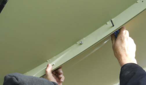


7 Installation Photos: Additional Help for Installing by Sections to the Ring Template Rib Color Coded Dot on Rib Back Brace Tab Block Template Rib Continue to page 4A for section by section antenna installation or see page 4AB for additional photo helps Page 4AA


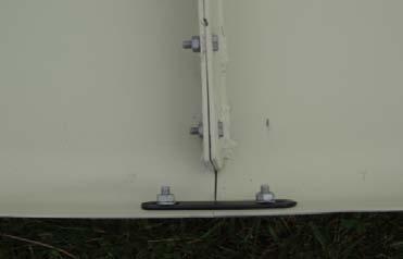


8 Installation Photos: Additional Help for Installing by Sections to the Ring Splice Strap Back Brace Brace Clip Continue to page 4A for antenna section by section installation Page 4AB
 SEE Page 4AA & 4AB for photo helps Assemble mount and put mount in")
 STEP 1: Install the brace clips to all 8 back braces, using a 3/8 x 2 bolt, 3/8 nut and 3/8 lock washer before placing on the")
 STEP 2: Install brace clips to the ends of the 8 back braces and install the ½ nut on the threaded rod end of the back brace,")

.")
.")
 TIP: To assist on holding the rubber washer placed between the block and the antenna we suggest using a piece of electrical tape to hold the rubber washer to")


9 See: DH Satellite YouTube Video SECTIONAL ANTENNA ASSEMBLY METHOD (Install By Sections to ring: Using 2-3 People) SEE Page 4AA & 4AB for photo helps Assemble mount and put mount in birdbath position. Be sure to lock the mount with ratchet straps once in birdbath position. (See picture C, birdbath below) STEP 1: Install the brace clips to all 8 back braces, using a 3/8 x 2 bolt, 3/8 nut and 3/8 lock washer before placing on the antenna lip and ring. Have all 8 brace clips installed on the brace before going to the next step. See brace clip and back brace photos below. (details to install in Step 2) STEP 2: Install brace clips to the ends of the 8 back braces and install the ½ nut on the threaded rod end of the back brace, threading it down approximately 4 to 4 ½ down the threaded rod (see FIG. #13 and #14). STEP 3: Take the first panel and install it to the ring of the mount finger tight. Be sure to find the pilot hole on the mount and on the antenna. The pilot hole is located on the 2 nd block from the left of the weld on the ring from the back view of the antenna. The pilot holes are used for a starting point only. (see picture D). Take the back brace that is ready and put the threaded rod through the tab on the ring (see picture A). Take the other end of the rod with the clip and attach the brace and clip to the lip of the antenna section (see picture B). STEP 4: Insert ½ x 3 bolt from the antenna to the mount. (see FIG. #17) TIP: To assist on holding the rubber washer placed between the block and the antenna we suggest using a piece of electrical tape to hold the rubber washer to the block. Have one person continue holding the panel in place while the second person attaches the back brace. (Remember the threaded end of the back brace should already have the ½ nut on the threaded end about 4-4 ½ on the threaded rod and the bent tab already installed on the ring, see FIG. #15). Insert the threaded rod of the back brace into the bent tab and bolt brace clip on the edge of the antenna with 1/4 x 3/4 bolt, 1/4 nut and 1/4 lock washer. Make sure everything is finger tight. STEP 5: Pick up the second antenna panel and be sure the numbers line up and bolt in place just like the first panel. (see FIG. #9) Once secure you can begin bolting the two units together by placing the ¼ x ¾ bolts through the templates. Again only finger tight. Continue for remaining panels. STEP 6: You will notice all 8 bolts in the face of the antenna have been installed from the antenna to the ring at this point. You now remove every other bolt from the face of the antenna and replace them with a feed strut. (See preparing the feed assembly on page 6) FIG. #13 Brace Clip FIG. #15 48 Ring PICTURE A 1/2 x 1 1/2" Bolt Back braces are measured by tube length only. PICTURE B PICTURE B Fig 14 Block PICTURE AA Brace Tab Threaded 1/2 x 3 Bolt FIG. #17 PICTURE D Weld Pilot Hole PICTURE C Match 2 with 2 FIG. # 9 Page 4A


10 PREPARING THE MOUNT TO RECEIVE THE ANTENNA **SPECIAL NOTE: Disregard if you have a sectional antenna and skip to page 6. It is time to install the antenna to the mount. You must first elevate the ring to about 60 degrees. Lock it in place. Locate the 1/8" pilot holes; one is located next to one of the 8-1/2" holes in the dish and the other is found on one of the 8 blocks on the mount next to the 1/2" holes. When you have located these two holes you will need 2-3 people to help pickup the dish and set it into the ring making sure the pilot holes line up. Slip in the l/2" x 1 1/2" bolts using both a rubber & steel washer, leaving out every other bolt until the feed struts are in place. (see Fig.#1A) Do not tighten these bolts more than just snug. The feed struts should now be installed. Finish installing the remaining bolts, washers, and nuts to complete the assembly of the antenna to the ring mount. (Fig.#1) Please read page 6 & 7 Preparing the feed. You are ready to put the dish in a vertical position and use a ladder to assemble and install the feed horn. Install the bolts as in page 8, Fig.#3 for Ku band. DO NOT OVER TIGHTEN. Install the back braces finger tight. Refer to figures #2, #2A, #3, & #4 below. NOTE: 3.0m, 3.7m and 3.8m antenna systems have 15/16 galvanized round tube back braces. Please refer to mechanical drawing specifications on page 5A. There are eight holes around the rear of the 48" ring to accept the braces. See Fig. #3. The angle clip( bent tab, (Fig.#2) is a piece of steel, bent in the middle approximately 1 l/2"x 3" long with two 1/2" holes. You will find these in the bolt bag. First fasten the clip with 1/2" bolts to the 48" ring; now thread one 1/2" nut about 2/3rds of the way down on the 1/2" rod end of the brace. Slip the rod end through the clip and install another 1/2" nut. Only tighten these finger tight. Now, go to the edge of the dish and place the two 1/4" x 3/4" bolts thru the predrilled holes in the lip (Refer to Fig. #4) of the dish and into the end of the brace and tighten with 1/4" nuts. Repeat this for all eight braces. Set the dish in its normal position for tracking the arc and walk 30 feet away and sight the front surface of the dish. It should be flat. If it is not, adjust any brace that may be holding pressure and try to make the front surface flat. Try to do very little adjusting and try to release pressure to make the antenna as flat as possible. Fig. 1A Feed struts Figure #2 Fig.#2A 1/2 x 1 1/2" Bolt Figure #3 Back braces are measured by tube length only. 37 for both the 3M 1pc & 3M 4pc The 4pc 3.7M has a 3/4" x 50 and the 3.8m brace is 53 long. 3/4" x 37" 1pc 3M or 4 pc 3M Figure #4 Brace clip Figure #1 Block Splice strap 1/2 x 3 Bolt Page 5
11 48" MOUNT Tab for square back brace 3/4" 5/16" 3 7/8" 3/4" 3/4" 1/8" 1/4" SQUARE TUBING BACK BRACE NEW 3/8" 3/8" Hole 1 1/2" 1/8" FLATTENED WITH DIE 1/2" threaded rod 3/8" 3/8" Hole 1 1/2" 5/16" 1/8" 48" MOUNT Tab for round back brace 3/4" 3 7/8" 1" 3/4" 1/8" 15/16" o.d. ROUND TUBING BACK BRACE NEW 37"= 3.0m 50"=3.7m 53"=3.8m 60" MOUNT 15/16 o.d. ROUND TUBING BACK BRACE NEW 2" 1/4" FLATTENED WITH DIE 1/2" threaded rod 6" 60" MOUNT 37"=3.0m 50"=3.7m 53"=3.8m 2" 6" 45"=3.7m 47"=3.8m 2" 6" 45"=3.7m 47"=3.8m 55 1/4"=4.2m 62.5"= 4.5m 68.5"= 5m 2" 6" 3/8" HOLE 1/2" 2" 6" 3/8" HOLE 1/2" 2" 6" Back Brace Brace bracket 3/8" x 2" bolt/nut Edge of Antenna DESCRIPTION: DRWN BY: SCALE: DH SATELLITE P.O. BOX 239 PRAIRIE DU CHIEN, WISCONSIN PHONE (608) BACK BRACES NEW DESIGN GILBERTS DATE; REVISED: NOT TO SCALE DRWG#: back brace new


12 New style collar C14F2018 transition will start April 16 th, 2018 please refer to page 6A for setup. FINE TUNING THE ANTENNA Plan to take an extra hour of your time to get the most from your antenna. We recommend using a Spectrum Analyzer to do this or A1 Turbo S2 made by Applied Instruments. With each adjustment you make you will be able to see your increase/decrease in gain. To begin you must string the antenna. This is done by simply taking a string, tying it to one brace and running the string across the front of the antenna to the other brace at 180 degrees and tying it so it is taut. Now tie another string to a brace 90 degrees from the first brace and running it to the corresponding brace 180 degrees away. Be sure you put the string on top or under the other string so as to not touch each other. When done you should have two strings at 90 degrees and they should meet in the center of the antenna. (Ideally you should use four strings at approximately 45 deg. apart.) If the strings don't touch at the center, then you will have to do some adjusting with the braces. Be sure your strings are taut. Stand back about 30 ' and sight the antenna again and see where you must apply pressure with the braces or relieve the pressure from an area. Now go ahead and make small adjustments with the braces, each time checking with the Spectrum analyzer to see that you are increasing the gain of the antenna (See also page 9). PREPARING THE FEED ASSEMBLY You will find below the focal lengths and focal length/diameter ratios for our commercial 3M, 3.7M & 3.8M antennas. This information is necessary to set the antenna and feed up properly. Measuring the f/l 10' (3m) 36"f/l.3 f/d 12 (3.7m) 57.6 f/l.4 f/d 12 5 (3.8m) 57.6 f/l.378f/d 35 ¾ OR 57 3/8 Below you will find a list of feed collars that are available to purchase from DH Satellite. (See Fig #1 - #4) Your DH representative should have asked you what type feed you will be using. We need this information to be assured we are sending the proper collar to attach your feed to our struts. Take the collar and set it on the back of the scaler ring of the feed horn. Turn it until all three holes line up between the two and insert the 1/4 "x 3/4" bolts thru the scaler ring and then thru the collar. Fasten with the 1/4" nuts. Most C-band and dual feeds have a 3-bolt pattern on the scaler just for this. Now, slide the end of the strut thru the feed bracket as shown in drawing #1 and attach each leg w/ 2-¼ x 1 1/2 bolt & nut. Do this on all four struts. Refer to Fig.#5. Place the flattened end of the struts onto the antenna and use the 1/2 x 3" bolts to fasten to the dish. Use every other hole. Check to see the feed is at the focal length, and then tighten all bolts. The actual focal length should be 1/4" inside the waveguide for C-band. DH Collars C14F (Chaparral collar with conduit struts): C Band C14FHD (Chaparral collar with heavy duty struts): C Band, C/Ku C24HD (Seavey collar with heavy duty struts): C Band, C/Ku KU4FL: Ku Band ONLY Fig. #5 C14F 1/2" x 3 Bolt 1/4 x 1 1/2 Bolt Collar 1/4 Lock Washers & Nuts Conduit Feed Strut 1/2 Rubber Washer Antenna Surface 1/2 Steel Washer 1/2 Nut C14F COLLAR & STRUTS KU4FL COLLAR & STRUTS C14FHD COLLAR & STRUTS C24HD COLLAR & STRUTS Fig. #1 Fig. #2 Fig. #3 Fig. #4 SPECIAL NOTE: Fig. #1 & #3 are used primarily with Chaparral and ADL C band and C/Ku band feed horns. Fig#3 is a special order Heavy Duty feed strut system and may be purchased at an additional cost. Figure#4: Our C24HD is a special order Heavy Duty system set up for Seavey manufactured C & C/Ku band feeds. This may be purchased at an additional cost. Refer to the drawing on page 7 for the bolt placement of a C14FHD or C24HD. Page 6
13 Preparing the C Band Feed Assembly C14F2018 If the feedhorn you have selected has an adjustable scalar ring, move it to the proper wave guide setting as per the manufacturer's instructions. Below we have listed the focal lengths and focal length diameter ratios for our commercial antennas. Just find your antenna and you will have the information to set the scalar properly. Special Note: More critical than setting the wave guide to the manufacturer's recommendations is to make sure you are setting the feedhorn at the correct focal length of the antenna. Antenna Size Focal Length Focal Distance 10' (3.0m) 36" f/l.3 f/d 12' (3.7m) 57.6" f/l.4 f/d 12 5 (3.8m) 57.6 f/l.378 f/d NOTE: C14F2018 Strut length includes bend in measurement. Your DH representative should have asked you what type feed you will be using. We need this information to be assured we are sending the proper collar to attach your feed to our struts. A DH C14F2018 is supplied as standard unless you have made a request for another style collar. Place the C14F2018 collar or collar supplied on the back of the feedhorn scaler ring. Turn the scaler plate off the feedhorn so that all three holes line up between the slotted holes on the feed collar. Insert the 1/4" x 3/4" bolts through the scalar ring and then thru the collar; fasten with the 1/4" nuts. (Most C-band and dual feeds have a 3-bolt pattern on the scalar ring as described above). For CHAPARRAL type feeds, refer to Figure #10. Slip the feed strut into a tab on the collar and line up the two holes. Insert the 2 5/16 x 3/4 bolts into the holes and tighten with the 5/16" nuts. Proceed with all four struts then check focal length and tighten down. Use every fourth hole. The actual focal length should be 1/4 inside the waveguide for C-band and 1/8 for Ku band. 5/16 x 3/4 Bolt Collar Figure # 10 C14F2018 5/16 Lock Washers & Nuts 1/2" x 3 Bolt C14F2018 Refer to the drawing on page 7 for the bolt placement of a C14FHD or C24HD. 3/4 Feed Strut 1/2 Rubber Washer Antenna Surface 1/2 Steel Washer 1/2 Nut For use of Chaparral Feeds C14F2018 Page 6A
14 C14F-HD/C24HD 48" MOUNT Notes This strut is used for 48" mount with: HD Feed collar Black painted end goes toward the Antenna on 48" Mt Use the top 2 holes on the strut for the C14HD or C24HD Bolt goes through the 1-1/2" wide side of the feed strut Use the top 2 holes on this end when using a 48" mount ring w/hd Collar 1 15/16" 7/8" 3/8" 3" All Holes 11/32" dia. 11/32" Holes 11/32" Holes 3.7m, 3.8m, 4.2m, 4.5m uses 58" x 1" x 1 1/2" Struts 3 meter uses 37 5/8" x 1" x 1 1/2" Struts Black Painted strip on this end 1 11/16" 5/8" 3/8" 1" 1 1/2" C14F-HD or C24HD COLLAR This bolt hole not used This bolt hole not used 5/16" x 2 1/4" Bolts Feed Struts 5/16" x 1 1/2" Bolt Antenna 1/2" x 3" Bolt 2" x 2" Angle Brackets Top hole is for Chaparral type feed Bottom hole is for Seavey type feed DESCRIPTION: DRWN BY: SCALE: DH SATELLITE P.O. BOX 239 PRAIRIE DU CHIEN, WISCONSIN PHONE (608) Feed Assembly for 48" Ring: C14F-HD/C24HD MD/GILBERTS DATE; REVISED: NOT TO SCALE DRWG#: C14HD feed for 48ring
 and add in a three-piece flat collar to hold the Ku band feedhorn.")
.")

. (See Fig.")

15 NOTE: New style collar C14F2018 transition will start April 16 th, Set up instructions on page 6A. KU BAND FEED ASSEMBLY The Ku band collar is only used when you are using KU band only feeds. You will use our horseshoe collar C14F or C14F2018 (see photos below) and add in a three-piece flat collar to hold the Ku band feedhorn. When using these to pieces together we call it a KU4FL (see figure #2) First assemble two pieces of the flat tri-collar, slide it onto the feedhorn, and then add the last piece. Attach the flat tri-collar to the horseshoe collar (fig#2). You will notice that you can adjust the polarization of a single feed by rotating your feed to the desired position and then tighten the tricollar to the feedhorn. This will prevent the feedhorn from sliding. Major adjustments in your focal length can be made by placing the threepiece collar on either side of the horseshoe collar. FINE TUNING THE FEED Set the feed at the exact focal length we recommend. It will either be a 36" or 57.6 f/l. (This does not take into consideration the allowance for the feed manufacturer's recommendation that the focal length be 1/4" inside the waveguide for C-band and 1/8" for Ku band). (See Fig.#4) You must set the feed so that you are looking directly at the center of the dish. Use a focal finder or anything handy to assist in aiming the feed to the center of the dish. The feed must not be tilted in any way. DH offers a new focal finder tool to assist in centering the feed. Call for pricing. FIG.#1 FIG.#4 35 7/8 OR 57 ½ FIG.#2 FIG.#3 FOCAL LENGTH C14F KU4FL KU4FL W/ DH STRAIGHT THRU FEED KU4FL USING C14F2018 COLLAR KU4FL W/DH STRAIGHT THRU FEED USING C14F2018 COLLAR C14F2018 NOTE: New style collar C14F2018 transition will start April 16 th, The feed plate has flex so that when setting up the collar you will be able to achieve the correct position regardless of the collar you have received. Once you tighten all of the hardware on the feed assembly, the flex will be established and tightened into place. It is VERY important that, 24 hrs after installation, a final inspection is completed on the feed assembly. You will need to recheck the focal length and make sure your feedhorn is looking directly at the center of the dish. This step is necessary 24 hrs after installation and if you make any future adjustments to the feed assembly. Please take time to read over page 9 on ADDITIONAL FINE TUNING TECHNIQUES. Page 8


 or to make a tool to assist in finding the center of")
16 ADDITIONAL FINE TUNING TECHNIQUES To receive the optimum from your antenna, you must take time to fine tune the antenna. What are the antenna adjustments? They are: make the front surface flat, be sure the feed looks at the center of the dish, and set the proper focal length. You must also be pointed at the satellite and have the feedhorn skew properly adjusted. Many of the adjustments are done without any measurement of the signal, and in fact require no signal at all. The adjustment of making the front surface flat, adjusting the focal length, and aligning the feed will be done without signal. You will use the strings and the back braces to make the dish flat, a focal finder and measure tape to align the feedhorn to find center, and set the focal length using a measure tape to measure from dish to feedhorn. You will use a satellite tool to locate signal in further steps of fine tuning. We feel that you must use strings to assure the front of the dish is flat. The strings must be taut and run from brace to the opposite brace at 180 degrees. A larger dish with 8 braces needs four strings. Do all adjustments with the braces loose. The strings must touch at the center, if they do not, sight the dish from the side to see which braces should be slightly adjusted to make the front surface of the antenna perfectly flat. CAUTION: do not over tighten the bolts that hold the dish to the ring as they can distort the dish. The easiest way to assure yourself that the feedhorn is looking directly at the center of the antenna is to use a Focal Finder (SEE PHOTO A BELOW) or to make a tool to assist in finding the center of the antenna. You can, if no focal finder is available, cut a 1 X 4 board to the length of the antenna s focal length. Held vertically against the feed it should point at the center of the antenna, this will be true at the horizontal plane as well. DH recommends using an A1 Turbo S2 made by Applied Instruments or another tool such as a spectrum analyzer to locate your satellite signal in order to complete the following steps: Setting the Azimuth: To set the azimuth of the system you will use the base can and a tool to locate and measure signal. Find a satellite signal using the A1-Turbo or another satellite tool that will show signal spiking. Any signal strength will work. This is your reference point. Now you will go from bad signal to bad signal. From this reference point you will move the antenna left of the reference point to see if the signal gets better or worse and right of the reference point to see if this makes it better or worse. When you see the location of the base can for the best signal, you will tighten down the set screws on the base can. (Special Note: It is best to make a mark on the pole and base can to reference your starting point before making any moves with the base can. Remark your base can and pole so that you now know the location that is allowing the strongest satellite signal.) Setting the Elevation: You will use the turnbuckle assembly to make this adjustment and again you will go from bad to bad signal and find the center point with the best signal strength. Again, to make this adjustment you will only use the turnbuckle. It is best to mark the starting point of the threaded rod or count the turns so you know exactly where you started before making slight adjustments with the turnbuckle assembly. Skewing the feedhorn: You will rotate the feedhorn again going from left or right of the marked reference location for your feedhorn to find your strongest signal. Once you find your strongest signal tighten down into place. Keep in mind when you are making these last Additional Fine Tuning Techniques very small moves will be needed to make the best improvements in signal strength. PHOTO A Focal Finder to Locate Center of Antenna A1 Turbo S2 Made By Applied Instruments Page 9

17 FINAL ASSEMBLY FOR POLAR TRACKING Set the axis (mount boom) the approximate same degrees as your latitude. See chart. The dish is tipped forward the amount of declination (from chart). The mount must point south. Some things should be set and some adjusted. The following should be set and then left alone, Dish front surface must be flat. Feed should be centered and have the proper focal length. Declination angle should be set. There are only two adjustments to polar track - 1 is elevation (latitude) the other is pointing south (very critical and very small movements are involved). Have your A1Turbo S2 by the dish. You need an inclinometer to set declination and boom angle and also a compass to find south. Find a satellite the closest to the south of you. Get a picture, adjust elevation. Try a satellite east or west and if your arc does not match the polar arc, you must adjust the base can east or west. If you go west and are under the satellite, do not raise elevation. Move the mount slightly west, also the same for east. A WORD ABOUT KU FREQUENCY Fig.#1 Installing the feed for 12 Gig & Digital is more critical than on C-Band. This is why DH has a special feed collar and struts just for the KU application, (see Fig. 1.) The center of the feedhorn must be exactly at the focal length. Also check to be sure the feedhorn is centered by measuring from edge of dish. Check to see that feed is pointed directly at the center of the dish. The f/l can be adjusted by sliding the feedhorn closer or farther away from the antenna through the three-piece collar. Major adjustments can be made by placing the three-piece collar on either side of the horseshoe collar. PO BOX 239 PRAIRIE DU CHIEN WI USA PH: Page 10
18 Polar Tracking a DH Antenna 1. Point the Antenna system at your most direct southern satellite for your longitude. 2. Set the boom at your site s latitude. 3. Ensure that the top cross bar of the mount is directly horizontal with the boom and that the boom is pointed north to south. 4. Measure the off-set for your site latitude: (if the site is at 43 deg. Lat and 91 deg. Long): Set the boom to 43 degrees and ensure the top bar is horizontal with the boom, measuring the rings position with a digital inclinometer. This particular site would have a 6 degree off-set. This means the ring should be around 49 degrees. (if you need to make adjustments to the offset, use the declination adjustment on the left and right side of the ring near the top of the ring and the bar). 5. Aim the antenna at the most southern satellite and then peak the signal from this satellite with the Applied Instruments Turbo S2 or your test instrument. Then you will need to move the base can on the pole very slightly to the left or right to peak the signal even further. 6. Once you are satisfied with the location of the base can, mark the base can and base post to reference your spot. This will also be your reference satellite that you will return to in the next steps. 7. Track to the next satellite using the drill to motor the antenna over east or west. Once a signal is obtained on the Turbo S2 or other instrument, slightly move the antenna east or west with the drill. Once this signal has peaked, choose another satellite that is 10 to 20 degrees further and motor over to its position to see if a signal can be obtained(for the site referenced 43 deg. Lat and 91 w long, the most southern satellite used was 91 deg, then the next satellite used to peak was 97 deg. Moving 10 or 20 degrees AMC11(131 deg.) was used.) Peak this satellite signal until you are happy with the signal. 8. Once you have peaked, make a slight turn on the turnbuckle, slightly moving the dish up and down. Using your Turbo S2 or other testing device, note if these adjustments make the signal better or worse. This will indicate if you are over or under the polar arc. Remember where the turnbuckle position started as you will need to put it back to this position. If you increased the signal strength lowering the dish, this indicates that you were shooting over the arch. If you increased the signal by raising the dish, this indicates you were shooting under the arc. The following will correct that. Adjusting arc 1. First, adjust the turnbuckle back to where it was before you made the move either up or down. Drive the dish back using a drill back to the most southern satellite that you started on and peak this signal out. Note: you must be peaked on your most southern satellite signal. Looking at the mark that was previously made on the can/pole, rotate the dish assembly and base can. 2. If the last satellite you attempted to peak the signal on had a better signal by turning the turnbuckle and dish down, you will need to move the base can to the East about 1/8. If the signal was stronger when you raised the dish, you will need to move the base can to the West about 1/8. 3.Tighten down a set screw and mark on the can and pole where you just moved it. Motor the dish slightly east or west to repeak the southern most satellite you used as your reference satellite. Slightly adjust the turnbuckle if needed to peak the signal even further.
19 4. Once you obtain the best signal strength, drive the dish over with a drill to the last few satellite signals that you had done previously. Note if the signal strength has improved from the adjustments that were just made. 5. Peak the satellite signal out on the farthest satellite you are trying to obtain(we used 131W). Note the signal and then adjust the turnbuckle again either up or down seeing if this increases or decreases the signal strength. If it does, you will need to repeat the steps under Adjusting arc until you are satisfied with the signal strengths with the satellite signals you are trying to obtain.
20 Technical: Cindy Wille or Nate Gilberts M-F 8AM 4:30PM CST or or C14F Feed Assembly 1- Set of Struts (4) 1-Collar 8-1/4 x 1 1/2 Bolts 8-1/4" Lock Washers & Nuts *New Style Collar C14F2018 *C14F2018 transition Starts April 16 th, 2018 Feed Assembly 1- Set of 4 Struts 1- Collar (C, Ku) 8-5/16 x 3/4 Bolts 8-5/16 Lock Washers & Nuts Feedhorn to Collar & LNB 3-1/4 x 3/4" Bolts 3-1/4" Lock Washers 3-1/4" Nuts (LNB to Feed) 20-1/4 x 3/4" Bolts 20-1/4" Nuts 20-1/4 Lock Washers BOLT BAG FOR: 48 POLAR MOUNT (3.0m, 3.7m and 3.8m) Ku4FL: 3PC ADD TO C14F 3- Section to 3pc collar x 1 Bolts ( 3pc Collar To Horseshoe) x ¾ Bolts 3- #8 Fender Washers Nuts Locking Bar 1-27 ½ Lock Bar 2-1/2" x 1 1/2" Bolts 2-1/2" Nuts 2-1/2 Lock Washers Heavy Duty Feed Struts C14F or C24 1- Set of 4 Struts 1- Collar (C, Ku) 12-5/16 Lock Washers & Nuts 4-2' x 2' Angle Brackets 4-5/16 x 1 ½ Bolts 8-5/16 x 2 ¼ Bolts Turnbuckle 1- Turnbuckle 2-1/2 x 1 1/2 Bolts 2-1/2 Nuts 2-1/2 Lock Washers 1-8 Spade Bolt Back Braces 8- Back Braces 8-1/2" x 1 1/2" Bolts 8-1/2" Lock Washers 24-1/2" Nuts 8-Bent Tabs 8-Brace Clips 8-3/8" x 2" Bolts 8-3/8" Nuts 16-1/4" x 3/4" Bolts 16-1/4" Nuts 8-3/8" Lock Washers 16-1/4" Lock Washers Back Brace Length 3.0m- 37 Long 3.7m- 50 Long 3.8m- 53 Long 3/4 Set Screws (4) Actuator 2-1/2 x 2 1/2" Bolts 2-1/2" Nuts 2-1/2" Lock Washers Base Can to Mount 2-3/4" x 5" Bolts 2-3/4" Lock Washers 2-3/4" Flat Washers 2-3/4" Nuts Antenna to Ring 8-1/2" x 3 Bolts 8-1/2" Nuts 8-1/2" Lock Washers 8-1/2" Flat Washers 16-1/2" Rubber Washers NOTE: 3.0m, 3.7m and 3.8m antenna systems have 15/16 galvanized round tube back braces. *Highly Recommended On Systems With Galvanized Back Braces* Please use a rubberized spray or silicon sealant to coat the threaded rods on the end of back braces to help prevent corrosion. When doing annual maintenance on your antenna system please make sure to check as it may need to be reapplied. NOTE: Stainless steel or DURA-CON hardware provided. *DURA-CON is a corrosion resistant coating. DURA-CON : Problem of thread-galling is eliminated. NOTE: SECTIONAL ANTENNAS INCLUDE ADDITIONAL HARDWARE, SEE TABLES BELOW Template Rib Hardware: Sectional Antenna Size ¼ x ¾ Bolts ¼ Lock Washers ¼ Nuts 3.0M M M Splice Straps: Sectional Antenna Size Splice Straps ¼ x ¾ Bolts ¼ Lock Washers ¼ Nuts 3.0M M M Missing parts warranty: Factory warranty on missing parts is 30 days ARO. DH will supply parts and shipping Regular UPS at no charge for 30 days ARO within the continental US. Red label within the US is only covered by DH if notified within three days ARO. Missing parts warranty is void 30 days ARO. Page 11

21 COMMERCIAL WARRANTY PO BOX N MARQUETTE RD PRAIRIE DU CHIEN, WI USA 1(608) YEAR LIMITED WARRANTY ON SPUN ALUMINUM DH Antenna warrants to the original purchaser of our spun aluminum antennas and mounts that they will be substantially free from defects in materials and workmanship for 5 years. In the event of failure during the first year of ownership, DH Antenna will supply a new antenna and /or mount at no charge. (Delivery of antenna or mount, freight, and cartooning of return defective part and installation will be borne by purchaser.) After the first year, and each successive year, in the event of any failure of the antenna or mount, we will replace at a fee 1/5 of the current suggested price for each year of use. (Delivery of antenna or mount, freight, and cartooning of return defective part and installation will be borne by purchaser.) These warranties exclude damage incurred in delivery and installation, Acts of God, vandalism, and owner neglect or abuse. Warranty procedure is to contact the factory for authorization of repair or replacement and or return authorization. Freight for defect parts will be shipped as prepaid and will be assumed by the purchaser. dhsatellite.com A Division of Design Homes Inc. Manufactured in the USA
3.0M, 3.7M & 3.8M Antenna w/48 Polar Mount 1 PC or Sectional INSTRUCTION MANUAL
 3.0M, 3.7M & 3.8M Antenna w/48 Polar Mount 1 PC or Sectional INSTRUCTION MANUAL CONGRATULATIONS on obtaining your new DH Antenna and mount. The 48 polar mount has been designed with a 48 diameter ring
Installation Instructions for the
 Installation Instructions for the Standard AZ EL Mount Congratulations! You have now purchased the finest AZ-EL mount available. This unit has been designed to give you the most stable system to work on
HANDLING AND ASSEMBLY INSTRUCTIONS FOR TRUE FOCUS 3.0M, 3.8M AND 4.2M ANTENNAS WITH POLAR MOUNT
 HANDLING AND ASSEMBLY INSTRUCTIONS FOR TRUE FOCUS 3.0M, 3.8M AND 4.2M ANTENNAS WITH POLAR MOUNT Introduction SECTION 1 Thank you for purchasing one of our fine True Focus products. This manual covers the
1.2 METER SERIES 1130 Rx/O ANTENNA SYSTEM
 REVISION H April 20, 2016 ASSEMBLY MANUAL 1.2 METER SERIES 1130 Rx/O ANTENNA SYSTEM General Dynamics SATCOM Technologies 1700 Cable Drive NE Conover NC 28613 USA Phone 770-689-2040 www.gdsatcom.com 1.2
INSTALL INSTRUCTIONS WELCOME TO THE NEWAGE PERFORMANCE CABINETRY SERIES NEWAGE STEEL WELDED CABINETRY
 NEWAGE STEEL WELDED CABINETRY WELCOME TO THE NEWAGE PERFORMANCE CABINETRY SERIES ALL CABINETS MUST BE MOUNTED TO STUDS ON A SECURE WALL, AS PER THESE INSTRUCTIONS. FAILURE TO DO SO MAY RESULT IN SERIOUS
GlideRite Retractable Cover System For HotSpring & Tiger River Spas (except Classic & pre-2000 Landmark Spas)
") List of Contents Quantity Description 12 #10 x 1 ½ Flat Head Phillips Screw (see pg. 2) 2 #10 x ½ Pan Head Phillips Screw (see pg. 2) 8 ¼ x 2 ½ Lag Bolt (see pg. 2) 7 ¼ 20 x 5 / 8 Hex Head Bolt (see pg.
List of Contents Quantity Description 12 #10 x 1 ½ Flat Head Phillips Screw (see pg. 2) 2 #10 x ½ Pan Head Phillips Screw (see pg. 2) 8 ¼ x 2 ½ Lag Bolt (see pg. 2) 7 ¼ 20 x 5 / 8 Hex Head Bolt (see pg.
.84M Ku-Band Rx/O Antenna System
 4096-644 Revision A May 9, 2003 ASSEMBLY MANUAL.84M Ku-Band Rx/O Antenna System PRODELIN CORPORATION 1500 PRODELIN DRIVE NEWTON, NC 28658 .84M Ku-Band Rx/O Antenna System A ORIGINAL RELEASE 5/9/2003 A.Hahn
1.2M Ku-BAND Rx/Tx SERIES 1134 ANTENNA SYSTEM
 August 21, 1997 Revision D ASSEMBLY MANUAL 1.2M Ku-BAND Rx/Tx SERIES 1134 ANTENNA SYSTEM PRODELIN CORPORATION 1700 NE CABLE DRIVE CONOVER, NC 28613-0368 1.2M Ku-BAND Rx/Tx SERIES 1134 ANTENNA SYSTEM D
1.8 METER SERIES 1194 ANTENNA SYSTEM
 January 14, 2002 REVISION G ASSEMBLY MANUAL 1.8 METER SERIES 1194 ANTENNA SYSTEM PRODELIN CORPORATION 1500 Prodelin Drive Newton NC 28658 1.8 METER SERIES 1194 ANTENNA SYSTEM G Revise Address 1/14/02 F
May 14, Installation Manual
 May 14, 2012 Installation Manual Contents MAG TRACKER Components...1 Mount Installation...7 Module Installation & Grounding...11 Maintenance...14 Warranty......14 Contact Information......14 May 14, 2012
Install Instructions. NewAge Steel Welded Tall Locker
 Kit Contains Full Width Adjustable Steel Shelves (4) Height-Adjustable Steel Leveling Legs (4) Aluminum Door Trim (2) 2.5 x ¼ Cabinet Mounting Lag Bolts (4) Large Zinc Plated Mounting Washers (4) 5/8 x
GlideRite Retractable Cover System For Hot Spot Spas (SE & SLX only)
") List of Contents Quantity Description 12 #10 x 1 ½ Flat Head Phillips Screw (see pg. 2) 2 #10 x ½ Pan Head Phillips Screw (see pg. 2) 8 ¼ x 2 ½ Lag Bolt (see pg. 2) 7 ¼ 20 x 5 / 8 Hex Head Bolt (see pg.
List of Contents Quantity Description 12 #10 x 1 ½ Flat Head Phillips Screw (see pg. 2) 2 #10 x ½ Pan Head Phillips Screw (see pg. 2) 8 ¼ x 2 ½ Lag Bolt (see pg. 2) 7 ¼ 20 x 5 / 8 Hex Head Bolt (see pg.
1.8 METER SERIES 1184 ANTENNA SYSTEM
 REVISION F January 10, 2002 ASSEMBLY MANUAL 1.8 METER SERIES 1184 ANTENNA SYSTEM PRODELIN CORPORATION 1500 Prodelin Drive Newton NC 28658 1.8 METER SERIES 1184 ANTENNA SYSTEM F Revised Address 1/10/02
Before returning this product to the store of purchase
 Before returning this product to the store of purchase Contact Dee Zee if you experience the following problems: Missing Parts Installation Problems/Questions Warranty Questions 1.800.779.2102 Hours of
Gared Pro-S Portable Backstop
 Models: 9616 & 9618 Installation, Operation and Maintenance Instructions Please read all instructions before attempting installation or operation of these units SAVE THESE INSTRUCTIONS FOR FUTURE USE PUBLICATION
.98M Ku-BAND Rx/Tx ANTENNA SYSTEM
 Revision C January 2, 2002 ASSEMBLY MANUAL ANTENNA SYSTEM PRODELIN CORPORATION 1500 Prodelin Drive Newton NC 28658 ANTENNA SYSTEM C Revised Series text B Revised Address 1/2/02 RAH A Revise and Update
Flex Fence Instruction Manual
 The Safer Stronger Smarter Choice Flex Fence Instruction Manual Table of contents 2 3 4 4 5 5 6 7 8 10 10 11 11 12 13 13 15 18 18 19 20 22 Table of contents Supplies, tools and equipment Introduction Laying
Spring Loaded All Season Roll-Up Doors
 Spring Loaded All Season Roll-Up Doors STAND-OFF MOUNTING METHOD INSTALLATION INSTRUCTIONS READ THIS FIRST Carefully examine the crate(s) for damage before opening. If the carton is damaged, immediately
 INSTRUCTION BOOKLET #C10 Watch step by step installation instructions at: https://www.wallbedsbywilding.com/wallbed-installation-studio-series/ WARNING! ALL MURPHY/WALLBED SYSTEMS CONTAIN STORED ENERGY.
 INSTRUCTION BOOKLET #C0 Watch step by step installation instructions at: https://www.wallbedsbywilding.com/wallbed-installation-studio-series/ WARNING! ALL MURPHY/WALLBED SYSTEMS CONTAIN STORED ENERGY.
6' Wide Premium Greenhouse Benches
 6' Wide Premium Greenhouse Benches Premium Greenhouse Bench with Stationary Top 2015 FarmTek All Rights Reserved. Reproduction is prohibited without permission. STK# DIMENSIONS 112416S6X08 6' W x 3' H
Side Mount INSTRUCTION BOOKLET #C122 BED STYLE: PARK CITY
 Side Mount BED STYLE: PARK CITY INSTRUCTION BOOKLET #C1 WARNING! ALL MURPHY/WALLBED SYSTEMS CONTAIN STORED ENERGY. FAILURE TO USE AND FOLLOW THESE INSTRUCTIONS DURING THE INSTALLATION PROCESS COULD RESULT
SERIES M Ku-BAND Rx / Tx ANTENNA SYSTEM
 4096-432 June 15, 2011 REVISION D ASSEMBLY MANUAL SERIES 1125 1.2M Ku-BAND Rx / Tx ANTENNA SYSTEM General Dynamics 1500 PRODELIN DRIVE NEWTON, NC 28658 PRODELIN CORPORATION 4096-432 SERIES 1125 1.2M Ku-BAND
Assembly Instructions and Parts Manual JPSF-1 Fence and JPSR Rail Set #
 Assembly Instructions and Parts Manual JPSF-1 Fence and JPSR Rail Set #1002493 JET 427 New Sanford Road LaVergne, Tennessee 37086 Part No. M-708482 Ph.: 800-274-6848 Revision C3 02/2014 www.jettools.com
ANTENNA EXPERTS. Website: AP MHz. 2.4 Meters 30dBi. Gain
 ANTENNA EXPERTS E-mail: info@antennaexperts.in Website: www.antennaexperts.in AP-180030 1700 1900 MHz. 2.4 Meters 30dBi. Gain INSTALLATION MANUAL GRID PARABOLIC ANTENNA NOTICE: Installation, maintenance
https://www.wallbedsbywilding.com/wallbed-installation-studio-series/
 For Wallbed models: KING SIZE INSTRUCTION BOOKLET #C1 Watch step by step installation instructions at: https://www.wallbedsbywilding.com/wallbed-installation-studio-series/ WARNING! ALL MURPHY/WALLBED
INSTRUCTION BOOKLET #C21. For Wallbed models: KING SIZE
 For Wallbed models: KING SIZE INSTRUCTION BOOKLET #C1 WARNING! ALL MURPHY/WALLBED SYSTEMS CONTAIN STORED ENERGY. FAILURE TO USE AND FOLLOW THESE INSTRUCTIONS DURING THE INSTALLATION PROCESS COULD RESULT
 For Wallbed models: KING SIZE INSTRUCTION BOOKLET #C1 Watch step by step installation instructions at: https://www.wallbedsbywilding.com/wallbed-installation-studio-series/ WARNING! ALL MURPHY/WALLBED
Football Goal Posts MODEL SERIES: FGP400 and FGP600 series
 Football Goal Posts MODEL SERIES: FGP400 and FGP600 series Installation and Maintenance Instructions Please read all instructions before attempting installation of these units SAVE THESE INSTRUCTIONS FOR
3.8m Commercial Antenna TxRx King Post Mount
 ANTENNA SYSTEMS 3.8m Commercial Antenna TxRx King Post Mount INSTALLATION & ASSEMBLY INSTRUCTIONS LIMITED TWELVE (12) MONTH WARRANTY This PATRIOT ANTENNA equipment is warranted to be free from defects
INSTALLATION INSTRUCTIONS
 AUTOMOTIVE PRODUCTS, INSTALLATION INSTRUCTIONS PLATINUM 4 OVAL STEP BAR (90 BENT END) APPLICATION: 2010-2015 Dodge Ram 2500/3500 Mega Cab PART NUMBER: 21-3570, 21-3575, 23-3570, 23-3575, 25-3570, 25-3575,
INSPECTION AND CORRECTION OF BELLHOUSING TO CRANKSHAFT ALIGNMENT
 INSPECTION AND CORRECTION OF BELLHOUSING TO CRANKSHAFT ALIGNMENT BACKGROUND Proper alignment of the transmission input shaft to the crankshaft centerline is required in order to achieve the best results
INSTRUCTION BOOKLET #C20
 INSTRUCTION BOOKLET #C0 WARNING! ALL MURPHY/WALLBED SYSTEMS CONTAIN STORED ENERGY. FAILURE TO USE AND FOLLOW THESE INSTRUCTIONS DURING THE INSTALLATION PROCESS COULD RESULT IN SEVERE PERSONAL INJURY TO
Horizontal Cable Systems
 ALUMINUM RAILING INSTALLATION INSTRUCTIONS Horizontal Cable Systems 1) Check Contents Of Packages: Verify that all parts have arrived and that they match the packing list. 1A) Coastal applications: Confirm
6' Wide Premium Greenhouse Benches
 6' Wide Premium Greenhouse Benches Premium Greenhouse Bench with Rolling Top 2015 FarmTek All Rights Reserved. Reproduction is prohibited without permission. STK# DIMENSIONS 112416R6X08 6' W x 3' H x 8'
Horizontal Cable Systems
 ALUMINUM RAILING INSTALLATION INSTRUCTIONS v2012 orizontal Cable Systems 1) Check Contents Of Packages: Verify that all parts have arrived and that they match the packing list. 1A) Coastal applications:
INSTRUCTION BOOKLET #34. For Wallbed models: KING SIZE SIERRA WITH STORAGE HEADBOARD
 For Wallbed models: KING SIZE SIERRA WITH STORAGE HEADBOARD INSTRUCTION BOOKLET #34 WARNING! ALL MURPHY/WALLBED SYSTEMS CONTAIN STORED ENERGY. FAILURE TO USE AND FOLLOW THESE INSTRUCTIONS DURING THE INSTALLATION
ASSEMBLY INSTRUCTIONS FOR T-10, T-11 & T-12 SERIES RACKS
 ASSEMBLY INSTRUCTIONS FOR T-10, T-11 & T-12 SERIES RACKS T12SHD-1 with 26 Legs shown above. Package Contents: HARDWARE KIT PARTS (8) 3/8-16 x 3 CARRAIGE BOLTS (1) RAIL DRIVER S SIDE ASSEMBLIES (20) 3/8-16
Sunset Swings By Health in Motion, LLC
 Sunset Swings By Health in Motion, LLC Model 421 Lounge Swing Assembly and Operation Manual Record Serial Number Here www.sunsetswings.com by Health In Motion, LLC. 11/6/2009 421 Owners Assembly and Operation
Worktop INDEX eight Capacity Unpacking
 Pro.0 Series Warning: Excessive weight hazard! Use two or more people to move, assemble or install cabinets and locker to avoid back injury. Do not leave children unattended near cabinets. High risk of
Installation Instructions. Tools Needed. Tape measure. Level. Shovel or Post hole digger. Concrete. Drill. Stakes. Mallet or hammer.
 Installation Guide EcoStone Fence 1330 West 400 North Orem, UT 84057 Toll Free 1.866.648.9336 Tel. 1.801.655.5236 Fax 1.801.655.5240 www.ecostonefence.com Installation Instructions Introduction. These
Part# 85200, 86200, 85095, 86095, TC200,TT200,TC095,TT095
 Part# 85200, 86200, 85095, 86095, TC200,TT200,TC095,TT095 Bag Hardware: (8) 5/16 x 1 ½ Allen flat head (14) 3/8 x 1 Hex bolt G5 (2) ½ x 2 ½ Hex Bolt G5 (6) 5/16 flange nuts (14) 3/8 flange nuts (2) ½ stove
PHG-1000X. Owner s Manual HOME GYM
 HOME GYM Owner s Manual WWW.BODYSOLID.COM THERE IS A RISK ASSUMED BY INDIVIDUALS WHO USE THIS TYPE OF EQUIPMENT. TO MINIMIZE RISK, YOU MUST FOLLOW THESE RULES:! " # $ % & ' ( ) * + ' (, ' " -. *, * ) )
INSTALLATION INSTRUCTIONS FOR SL-LB MANUAL LIFT BARRIER GATE ARMS
 INSTALLATION INSTRUCTIONS FOR SL-LB MANUAL LIFT BARRIER GATE ARMS Questions? Call 520-780-9751 or visit our website at: www.barriergatearm.com YOUR SL-LB MANUAL LIFT BARRIER GATE ARM WILL ARRIVE WITH WEIGHT
JK Rear Crusher Flares
 INSTALLATION INSTRUCTIONS INST-17-05-010_A JK Rear Crusher Flares IMPORTANT: Thank you for purchasing this Poison Spyder product. Please read through this entire document before proceeding with installation.
INSTALLATION INSTRUCTIONS
 INSTALLATION INSTRUCTIONS For Wallbed models: Do-It-Yourself BOOKLET #C90 WARNING! ALL MURPY/WALLBED SYSTEMS CONTAIN STORED ENERGY. FAILURE TO USE AND FOLLOW THESE INSTRUCTIONS DURING THE INSTALLATION
JK Front Crusher Flares
 INSTALLATION INSTRUCTIONS INST-17-03-030_A JK Front Crusher Flares IMPORTANT: Thank you for purchasing this Poison Spyder product. Please read through this entire document before proceeding with installation.
HD installation guide
 JANUS INTERNATIONAL 1 866 562 2580 www.janusintl.c o m 1950 1950HD installation guide RIGHT DRIVE END SHOWN LH OPPOSITE LEFT TENSION END SHOWN RH OPPOSITE PUSH-UP OPERATION 1950 1950HD SHOWN A rolling
400A 40113V, 401A 40120V, & 401AL 40120VL ALUMINUM VERTICAL 4000 LB LIFT INCLUDES SCREW LEG ASSEMBLY INSTRUCTIONS
 12/11/07 PAGE 1 OF 12 400A 40113V, 401A 40120V, & 401AL 40120VL ALUMINUM VERTICAL 4000 LB LIFT INCLUDES SCREW LEG ASSEMBLY INSTRUCTIONS Thank you for purchasing our product! *Please read these instructions
Model #SH & CH SH Pine CH Naturaline
 Model #SH304-101 & CH304-101 Assembly Manual SH304-101 Pine CH304-101 Naturaline Component Parts A 2 ea. Angled Rail - 2 x 4 x 107-1/8" B 1 ea. Center Angled Rail - 2 x 4 x 107-1/8" C 9 ea. Rock Board
Standard Pole Mount Parabolic Antenna Mounting Instructions 3 ft. (90cm) & 4 ft. (120cm)
 & 4 ft. (120cm)") 495 R Billerica Ave. N. Billerica, MA 01862 USA Tel: (978) 459-8800 Fax: (978) 459-3310 / 8814 www.radiowavesinc.com email: sales@radiowavesinc.com Standard Pole Mount Parabolic Antenna Mounting Instructions
495 R Billerica Ave. N. Billerica, MA 01862 USA Tel: (978) 459-8800 Fax: (978) 459-3310 / 8814 www.radiowavesinc.com email: sales@radiowavesinc.com Standard Pole Mount Parabolic Antenna Mounting Instructions
ASSEMBLY INSTRUCTIONS FOR HAULER II SERVICE BODY A RACK
 ASSEMBLY INSTRUCTIONS FOR HAULER II SERVICE BODY A RACK T12USBA-1 shown above Package Contents: HARDWARE KIT PARTS (4) 3/8-16 x 3 CARRAIGE BOLTS (1) RAIL DRIVER S SIDE ASSEMBLY (20) 3/8-16 x 2 CARRAIGE
CertainTeed INSTALLATION GUIDE SIMTEK FENCE PRODUCTS. Fence Installation Guide 3', 4' & 6' High
 CertainTeed INSTALLATION GUIDE SIMTEK FENCE PRODUCTS Fence Installation Guide 3', 4' & 6' High INSTALLATION GUIDE These instructions are designed to assist both professional installers and do-it-yourselfers
WILDING WALLBEDS INSTALLATION INSTRUCTION Side Mount
 WILDING WALLBEDS INSTALLATION INSTRUCTION Side Mount For Wallbed models: Do-It-Yourself Insturction booklet C92 WARNING! ALL MURPHY/WALLBED SYSTEMS CONTAIN STORED ENERGY. FAILURE TO USE AND FOLLOW THESE
Nancy s Knit Knacks LLC 4 Yard Option Upgrade Kit Assembly Instructions and User Manual
 Nancy s Knit Knacks LLC 4 Yard Option Upgrade Kit Assembly Instructions and User Manual Thank you for purchasing our 4 Yard Option (4YO) Upgrade Kit. To install this upgrade you are simply going to assemble
RBP-1215B-RX DODGE RAM QUAD CAB RX3
 RBP-1215B-RX3 2002-2017 DODGE RAM 15-3500 QUAD CAB RX3 Passenger side RX-3 Side Step Drill Template Passenger side rear Modular Bracket (6) L Support Brackets Driver side rear Modular Bracket Driver side
1.2M Ku-BAND Rx/Tx SERIES 1132 ANTENNA SYSTEM
 August12, 2003 ASSEMBLY MANUAL Revision E 1.2M Ku-BAND Rx/Tx SERIES 1132 ANTENNA SYSTEM PRODELIN CORPORATION 1500 Prodelin Drive Newton NC 28658 1.2M Ku-BAND Rx/Tx SERIES 1132 ANTENNA SYSTEM E Revised
(6) Plastic Retainers. Passenger/Right. Passenger/Right Support Brackets
 Plastic Retainers. Passenger/Right. Passenger/Right Support Brackets") PART#R102580 PARTS LIST: 1 Driver/Left HD Running Board 4 8mm Bolt/Nut Plates 1 Passenger/Right HD Running Board 4 8mm Plastic Retainers 2 Driver/Left & Center Mount Bracket 14 8mm-1.25 x 30mm Hex Bolts
PART#R102580 PARTS LIST: 1 Driver/Left HD Running Board 4 8mm Bolt/Nut Plates 1 Passenger/Right HD Running Board 4 8mm Plastic Retainers 2 Driver/Left & Center Mount Bracket 14 8mm-1.25 x 30mm Hex Bolts
Modular XP Ramp Assembly Manual
 Modular XP Manual 1 Contents Overview... 2-5 1.1 Tools required...6 1.2 Hardware list...6 Ramp & Platform Standard Parts 2.1 Ramp Parts...7 2.2 Platform Parts...8 2.3 Standard Platform Configurations...
DH SOLAR TRACKER INSTALLATION MANUAL BOLT TOGETHER FRAME
 DH SOLAR TRACKER INSTALLATION MANUAL BOLT TOGETHER FRAME Some history of this product. We began spinning parabolic aluminum antennas in 1980 with our 5 meter commercial antenna and tracking mount. We have
ClearSpan End Frame Kit 30' Wide x 11' High
 ClearSpan End Frame Kit 30' Wide x 11' High Diagram shows the end frame kit for an end wall without a door. (Door and end panel are purchased separately.) Rafter and mounting feet shown in the above diagram
SB-WM-ART2-L-BL SB-WM-ART2-XL-BL
 SB-WM-ART2-L-BL SB-WM-ART2-XL-BL Weatherproof Universal Dual-Arm Articulating Mount for Large TVs INSTALLATION MANUAL WARNING The maximum weight of this wall mount is 150 lbs (68.04 kg). Use with heavier
MM540 Installation Instructions IMPORTANT SAFETY INSTRUCTIONS - SAVE THESE INSTRUCTIONS
 MM50 Installation Instructions IMPORTANT SAFETY INSTRUCTIONS - SAVE THESE INSTRUCTIONS Please read this entire manual before you begin. Do not unpack any contents until you verify all requirements on PAGE.
INSTALLATION INSTRUCTIONS FOR FRONT CASTING DECK RAIL Ranger
 INSTALLATION INSTRUCTIONS FOR FRONT CASTING DECK RAIL Ranger TOOLS REQUIRED FOR INSTALLATION: Drill motor, (1) 5/16 inch drill bit, (1) 13/64 drill bit, (1) 3/16 inch hex wrench (1) 3/32 inch hex wrench.
Hollywood Swing Away 2 and 4 Bike Racks Assembly and Installation Guide
 Hollywood Swing Away 2 and 4 Bike Racks Assembly and Installation Guide Tools Required: two adjustable wrenches, pliers, ¾ socket wrench recommended Note: please do assembly near your vehicle as you Can
Assembly Instructions and Parts Manual JPSF-1 Fence and JPSR Rail Set
 Assembly Instructions and Parts Manual JPSF-1 Fence and JPSR Rail Set WALTER MEIER (Manufacturing) Inc. 427 New Sanford Road LaVergne, Tennessee 37086 Part No. M-708482 Ph.: 800-274-6848 Revision C2 02/2013
FENCE INSTALLATION GUIDE 8 HIGH WALLS
 FENCE INSTALLATION GUIDE 8 HIGH WALLS 1.866.648.9336 www.simtekfence.com INSTALLATION GUIDE These instructions are designed to assist both professional installers and do-it-yourselfers of SimTek decorative
Gared Pro Portable Backstop
 Models: 5016, 5017, & 5018 Installation, Operation and Maintenance Instructions Please read all instructions before attempting installation or operation of these units PUBLICATION NO. 551754436 SAVE THESE
OWNER S MANUAL Table Tennis Table Patent Pending
 OWNER S MANUAL Table Tennis Table Patent Pending Be sure to write your model number and serial number here for future reference. You can find these numbers printed on the bottom of the table. MODEL # T8266
4" Oval Nerf Bar. Part No. A1007S/B. PARTS LIST: Qty Part Description Qty Part Description
 4" Oval Nerf Bar Part No. A1007S/B Fits: 2009 - Current Dodge Ram 1500 Crew Cab 2001 - Current Dodge Ram 2500/3500 Crew Cab REMOVE CONTENTS FROM BOX. VERIFY ALL PARTS ARE PRESENT. 60-180 min Cutting Not
Heavy Duty Ceiling Tilt Mount Installation Manual
 HD-CTM-5580 Heavy Duty Ceiling Tilt Mount Installation Manual *This Installation requires a minimum of two people. For your safety: Read the complete instruction manual before starting an installation
FENCE INSTALLATION GUIDE 6 HIGH FENCE
 FENCE INSTALLATION GUIDE 6 HIGH FENCE 1.866.648.9336 www.simtekfence.com INSTALLATION GUIDE These instructions are designed to assist both professional installers and do-it-yourselfers of SimTek decorative
INSTALLATION INSTRUCTIONS 3 ROUND & 4 OVAL SIDEBAR (90-DEG BENT END) DODGE RAM MEGA CAB PART NUMBER SB1214S SB1214B
 DODGE RAM MEGA CAB PART NUMBER SB1214S SB1214B") INSTALLATION INSTRUCTIONS PART NUMBER SB1214S SB1214B PARTS LIST: Qty Description Qty Description 1 Driver/Left Sidebar 4 12mm x 32mm OD x 3mm Flat Washers 1 Passenger/Right Sidebar 4 12mm Lock Washers
INSTALLATION INSTRUCTIONS PART NUMBER SB1214S SB1214B PARTS LIST: Qty Description Qty Description 1 Driver/Left Sidebar 4 12mm x 32mm OD x 3mm Flat Washers 1 Passenger/Right Sidebar 4 12mm Lock Washers
MODULAR TRACKER SOLAR
 SOLAR MODULAR TRACKER INSTALLATION INSTRUCTIONS Congratulations on purchasing a DH Solar Tracker! The DH Solar Tracker moves throughout the day with the use of a timed controller. Tracking throughout the
MantelMount. TM1A Installation Instructions IMPORTANT SAFETY INSTRUCTIONS - SAVE THESE INSTRUCTIONS
 MantelMount TMA Installation Instructions IMPORTANT SAFETY INSTRUCTIONS - SAVE THESE INSTRUCTIONS TM Thank you for choosing the MantelMount television wall mount. Please read this entire manual before
(W) INSTALLATION INSTRUCTIONS 3" ROUND & 4" OVAL SIDEBAR (90-DEG BENT END) DODGE RAM 1500 QUAD CAB PART #DZ /DZ /DZ /DZ
 INSTALLATION INSTRUCTIONS 3 ROUND & 4 OVAL SIDEBAR (90-DEG BENT END) DODGE RAM 1500 QUAD CAB PART #DZ /DZ /DZ /DZ") (W) INSTALLATION INSTRUCTIONS 3" ROUND & 4" OVAL SIDEBAR (90-DEG BENT END) PART #DZ 372231/DZ 372233/DZ 372237/DZ 372239 PARTS LIST: 3" ROUND & 4" OVAL SIDEBAR (90-DEG BENT END) Qty Description Qty Description
(W) INSTALLATION INSTRUCTIONS 3" ROUND & 4" OVAL SIDEBAR (90-DEG BENT END) PART #DZ 372231/DZ 372233/DZ 372237/DZ 372239 PARTS LIST: 3" ROUND & 4" OVAL SIDEBAR (90-DEG BENT END) Qty Description Qty Description
Side Winder R o u t e r L i f t.
 Woodpeckers PRECISION WOODWORKING TOOLS Side Winder R o u t e r L i f t. INSTALLATION INSTRUCTIONS The wrench handle must be pointing left in order to fully insert or remove it. Lift Wrench Once fully
VIEWPOINT ALUMINUM RUNNING BOARD TOYOTA RAV4
 PARTS LIST: VIEWPOINT ALUMINUM RUNNING BOARD 1 Driver/Left Running Board 4 10-1.5mm x 50mm T-Bolt 1 Passenger/Right Running Board 12 10mm Plastic Retainers 1 Driver/Left Bracket 2 10-1.50mm x 40mm Hex
MFJ-1835K34 40,30 METER ADD ON KIT FOR THE MFJ-1835 COBWEB ANTENNA INSTRUCTION MANUAL. CAUTION: Read All Instructions Before Operating Equipment
 MFJ-1835K34 40,30 METER ADD ON KIT FOR THE MFJ-1835 COBWEB ANTENNA INSTRUCTION MANUAL CAUTION: Read All Instructions Before Operating Equipment 300 Industrial Park Road Starkville, MS 39759 USA Tel: 662-323-5869
ALUMA-VENT AWNING REGULAR END STYLE INSTALLATION INSTRUCTIONS
 ALUMA-VENT AWNING REGULAR END STYLE INSTALLATION INSTRUCTIONS Contact us at: 1-888-442-2928 or www.americana.com Options in your kit: A. Splice Pg 16 B. Column Pg 17 C. C-Channel Brace Pg 19 D. Runner
SE5a Instrument Board part 2 - rev 1.1
 SE5a Instrument Board part 2 - rev 1.1 Fuel (Petrol) Valve This valve uses two circular name plates, eight brass screws, one black plastic base, copper wire and two black plastic risers. You can pick any
INSTALLATION INSTRUCTIONS 6 OVAL BENT END SIDEBARS DODGE RAM 1500, CREW CAB PART#: /241533B
 PARTS LIST: 1 Driver/Left Sidebar 24 8mm x 24mm x 2mm Flat Washers 1 Passenger/Right Sidebar 12 8mm Lock Washers 3 Driver/left, Passenger Center and Rear 6 8mm Hex Nuts 3 INSTALLATION INSTRUCTIONS 6 OVAL
INSTALLATION INSTRUCTIONS 3"/4 BENT END SIDEBARS FORD F-150 SUPERCREW PART # DZ /DZ
 INSTALLATION INSTRUCTIONS 09-12 FORD F-150 SUPERCREW PART # DZ 372697/DZ 372699 PARTS LIST: 1 Driver/Left Sidebar 4 1/2 Lock Washers 1 Sidebar 4 12mm x 32mm OD x 3mm Flat Washers 1 Driver/Left Mounting
ClearSpan PolyMax Windbreak Wall
 ClearSpan PolyMax Windbreak Wall Photo may show a different but similar model. 2007 ClearSpan All Rights Reserved. Reproduction is prohibited without permission. Revision date: February 2007ldg STK# DIMENSIONS
AWNING / PATIO COVER INSTALLATION INSTRUCTIONS
 AWNING / PATIO COVER INSTALLATION INSTRUCTIONS Before You Begin Read the installation instructions thoroughly before beginning the installation procedure. Perspective In the Awning Instructions, Back means
ClearSpan PolyMax Windbreak Wall
 ClearSpan PolyMax Windbreak Wall Photo may show a different but similar model. 2007 ClearSpan All Rights Reserved. Reproduction is prohibited without permission. Revision date: April 2007ldg STK# DIMENSIONS
BEAST THE. Tube and Pipe Notcher Operating Instructions. Notches In Bends Straight Notches. Angled Notches. Offset Notches
 Copyright (c) 2007 J D SQUARED INC. www.jd2.com THE BEAST Tube and Pipe Notcher Operating Instructions Notches In Bends Straight Notches Angled Notches PATENT PENDING Offset Notches Assembly After unpacking
Performance 2.0 Series
 Performance. Series Warning: Excessive weight hazard! Warning: Excessive weight hazard! Use two or more people to move, assemble, or install cabinets and locker to avoid back injury. Do not leave children
Clearview Railing System Installation Instructions
 Clearview Railing System Installation Instructions Disclaimer: AGS Stainless, Inc. has its Clearview Railing Systems designed by a professional engineer to meet the requirements of the latest national
INSTALLATION INSTRUCTIONS HEAVY DUTY TILT WALL MOUNT Model: PPH-2000
 INSTALLATION INSTRUCTIONS HEAVY DUTY TILT WALL MOUNT Model: PPH-2000 Specifications: Accomodates Akira and Orion 84" displays without interface bracket; accomodates other large flat panel displays with
7878 K940. Checkpoint Antenna. Kit Instructions. Issue B
 7878 K940 Checkpoint Antenna Kit Instructions Issue B Revision Record Issue Date Remarks A July 7, 2009 First issue B Nov2013 Revised the Checkpoint installation procedures for 7878 and 7874 scanners Added
Installation Instructions
 DODGE 16K Industry Standard Rail Custom Mounting Kit #2728 Gross Trailer Weight (Maximum)...16,000 lbs. Vertical Load Weight (Max. Pin Weight)...4,000 lbs. SYSTEM TOW CAPACITY Please note, in order to
SB-WM-ART1-M-BL. Weatherproof Universal Single-Arm Articulating Mount for Medium Displays INSTALLATION MANUAL
 SB-WM-ART1-M-BL Weatherproof Universal Single-Arm Articulating Mount for Medium Displays INSTALLATION MANUAL WARNING The maximum weight of this wall mount is 90 lbs (41 kg). Use with heavier than the maximum
QDV120 Operation and Pointing manual
 QDV120 Operation and Pointing manual MPAD1 Plus OP-080316-E1 page 1 Contents Item Description Page 1.0 Health and Safety for Operators and Installation Staff 3 2.0 Transit case Reflector/Mount/BUC/LNB
ASSEMBLY INSTRUCTIONS FOR HAULER II UNIVERSAL CAMPER SERIES RACKS
 ASSEMBLY INSTRUCTIONS FOR HAULER II UNIVERSAL CAMPER SERIES RACKS C11U2873-1 shown above Package Contents: HARDWARE KIT PARTS (4) 3/8-16 x 3 CARRAIGE BOLTS (1) RAIL DRIVER S SIDE ASSEMBLY (20) 3/8-16 x
SILVERBACK INSTALLATION MANUAL
 SILVERBACK INSTALLATION MANUAL R-SERIES SOLAR RACKS T OLL FREE 866-766-3727 WWW.ROOFSCREEN.COM Introduction... 2 The Silverback Solar Racking System... 2 This manual... 2 Application... 2 System Overview...
FOR PROFESSIONAL GARAGE DOOR INSTALLERS
 Composite Garage Doors Installation Instructions FOR PROFESSIONAL GARAGE DOOR INSTALLERS Tools required Screwdriver Claw Hammer Locking Pliers Power Drill Level with a 3/32" Drill Bit Utility Knife 9/16",
Assmann Corporation of America TANK INSTALLATION AND USE GUIDELINES FOR BULK STORAGE TANKS
 Assmann Corporation of America TANK INSTALLATION AND USE GUIDELINES FOR BULK STORAGE TANKS General Information Assmann polyethylene storage tanks are manufactured to give you the toughest, most reliable
ASSEMBLY INSTRUCTIONS FOR SERVICE BODY A MOUNT RACKS
 ASSEMBLY INSTRUCTIONS FOR SERVICE BODY A MOUNT RACKS T12 Service Body A shown with optional middle crossbar Package Contents: HARDWARE KIT PARTS (8) 3/8-16 x 3 CARRAIGE BOLTS (1) RAIL DRIVER S SIDE ASSEMBLIES
Please Do Not Return This Product To The Store!
 MODEL NO. T8176 QUICK SERVE 3000 TABLE TENNIS TABLE OWNER'S MANUAL 1. Read this manual carefully before starting assembly. Read each step completely before beginning each step. 2. Some smaller parts may