Installation Instructions for the
|
|
|
- Jessica Barker
- 6 years ago
- Views:
Transcription


1 Installation Instructions for the Standard AZ EL Mount Congratulations! You have now purchased the finest AZ-EL mount available. This unit has been designed to give you the most stable system to work on a single pole application. Assemble using these instructions. If you have any questions please call for help. The AZ-EL Mount is designed to go with the 3.0m, 3.7m, 3.8m, 4.2m and the 4.5 meter antennas. As all are identical in theory, we will cover the basic installation first and address each individually as the installation requires. PLEASE READ COMPLETE INSTRUCTIONS BEFORE BEGINNING INSTALLATION! HD Az-El option is available for the DH 4.5m antenna. If you will be storing the antenna for a period of time, we would prefer it to be laid flat on a level surface. Always store the antenna on its outer lip. Shipping Warranty for missing parts is detailed on the last page of the manual. A detailed parts list is provided on the page prior to the shipping warranty. Please refer to this section immediately on delivery. PARTS LIST 1 - DH Antenna 1 - AZ-EL Mount 60" Back Ring 1 5 1/2" I.D. Base Can 4 - Back Braces for 3.3m- See Note* 8 - Back Braces for 3.7m and larger **3m requires no back braces** 4 - Feed Struts 1 - Feed Collar 1 - Elevation Tube 1 - Elevation Tube Bracket 1 - Bolt Bag to include all Hardware (see page 14) 1 - Feed Cover *3.3m Discontinued After *3.9m Discontinued After Sectional antennas must be handled with care not to twist or distort sections while handling for installation. DH Satellite P.O. Box 239 Prairie du Chien, WI Phone: (608) Fax: (608) a.m. to 5 p.m. C.S.T. 03/22/2016
2 AZ-EL Mount 4.5m Fixed HD Az-El requires a 6 5/8 OD post to be installed with special pad design from DH. 2) Please contact DH for stand and prep work for this option. The 4.5m will install identically as all other antennas using the Az-El mount in this manual. Page 1
3 Installation of Base Post Look at the drawings below, the first drawing shows the recommended concrete base. In areas of deep frost, we recommend that the base go below frost levels. 1/2 rebar can be used to reinforce the structure, if required; contact your local concrete people or a local Engineer to give you an idea of how much steel to use. WE RECOMMEND THAT YOU CHECK WITH A LOCAL ENGINEER TO DETERMINE SOIL TYPE AND BEARING TO VERIFY THAT THIS BASE WILL WORK FOR YOUR LOCALE. With this AZ-EL mount, you have a choice of two different base assemblies. The first is a base post (see Figure #1). The base post is simply a 5 I.D. / 5 1/2" O.D. pipe that has one or more weldments on the lower section. We recommend that the post be in concrete at least 4'-0. When the post is set in concrete, be sure it is plumb. The second option is using either a square foundation or a sono tube shown in figure #2. Figure #1 Figure #2 Page 2

4 Installation of Base for the Four Leg Base Stand (continued) 2) The second base assembly is our Four Leg Base Stand (Figure #2). This unit is designed to go above ground on a concrete pad. You can install this either of two ways; number one, you can request a template of the base stand and install J -bolts in the concrete as you are pouring it, or you can wait until you receive the base stand (having previously poured the pad) and drill the holes into the concrete using the stand as a template. You must use a type of lead head or garonite (a parafast resin mortar) to secure the bolts. ** Most local concrete companies stock this type of product. *** If not available locally, DH Satellite can furnish the garonite. Concrete Pad for m Antennas Four Leg Base Stand Discontinued as of June 1 st, 2013 Garonite is a specially formulated, finley ground hydraulic cement. It expands while setting and will not loosen, shrink or crack under stress, vibration, heat or cold and will cure to strengths far exceeding those of regular concrete. Garonite does not contain metallic filings, calcium chloride or other corrosive agents. Garonite is supplied in ready-to-use form. Simply add water for special application when a high-strength, non-shrink, pourable consistency grout material is required, such as grouting heavy duty equipment when core drilling anchor bolts and base plates. Page 3
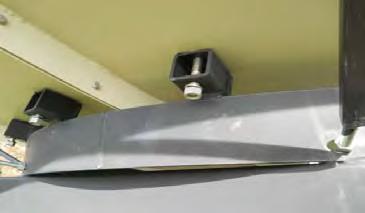
5 Assembling the Ring to the Base Assembling the AZ-EL Mount is very easy (familiarize yourself with Figure #3), as there are only four parts to put together. First take the base can and set it on the base post. Tighten it with the 3/4 set screws. Take the 60" ring and place each of the two ears inside of the tubes and line up the holes on the ears with the holes in the tubes. You will notice the 3/4" holes in the center on each of the 3 x 3 x 52 1/2" tubes welded to the 60" ring. Place the 3/4" x 5" bolts through the holes and secure with the lock washers and nuts provided. Place the elevation tube bracket onto the elevation tube. Tighten the set screws to hold it in place. Take the top end of the elevation tube, the end with the 3" x 6" plate welded on and place it in the brackets on the cross member of the ring. You will use a 3/4" x 3" bolt, lock washer and nut. Go to the elevation tube bracket and place the tab with the 3/4 hole into the tab brackets at the back of the base can. Secure it with a 3/4 x 3" bolt, lock washer and nut. Make sure the bolts are secure, but leave them slightly loose until you have aligned the antenna on the satellite you will be using. Once you have aligned the antenna, tighten all bolts and nuts. Page 4
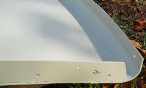
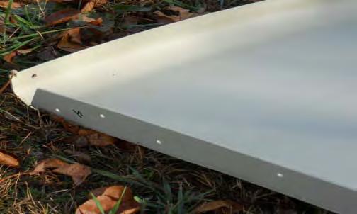
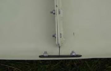
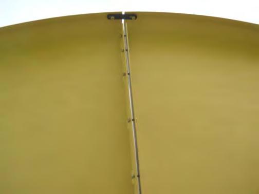
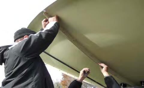
6 Assembly of the 2 Piece Antenna with Joiner Strips Disregard this section if you have a 1pc, 4pc, or 8pc Antenna. At this time the antenna will come in either one or two pieces when using the standard AZ-El mount. If you have requested your antenna be shipped in one piece, please ignore this paragraph and go on to the next page. Those of you who are left must take the two halves and place them on a flat surface. The antenna must always set on the lip when assembling or storing (see Figure #4). Before sliding the halves together, one person should get under the antenna with the 1/4" x 3/4" bolts supplied. Using the proper joiner strips, push the bolts from the inside out and secure with the 1/4" nuts. The joiner strips and the dish will have serial numbers that match, so when installing, be sure the numbers match. These numbers are on the inside lip of the dish and the end of the joiner strip (see Figure #5). Tighten these very tight so the dish holds the shape it had when made. Below is a listing of the additional number of 1/4" bolts that should be in your bolt bag when your antenna is in two pieces. 10' (3.0m) /4" x 3/4" bolts 11" (3.3m) /4" x 3/4" bolts Discontinued 12' (3.7m) /4" x 3/4" bolts 12' 9" (3.9m) /4" x 3/4" bolts Discontinued 14' (4.2m)... '36 1/4" x 3/4" bolts Figure # 5 Serial Number 1234 Jointer Strip 2pc antenna discontinued as of January 2013 Page 5
. NOTE: After complete installation you will no longer see the colored dots.")
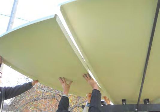
7 ASSEMBLY OF THE ANTENNA (On Ground: Lift As One Piece Antenna) IMPORTANT!! If you have purchased a 4 piece or 8 piece sectional antenna follow the instructions on page 6A and 6B. The antenna will come in 4 or 8 pieces each having a color coded dot on the rib (see FIG. #9). NOTE: After complete installation you will no longer see the colored dots. You must take two sections of the antenna and place them on a flat surface face down allowing for the installer to work on attaching the numbered ribs. The antenna must always stay in crate until assembled. (see FIG. #10). Take panel one labeled 08/1 and 08/2 and attach it to panel 2 which is labeled 08/2 on one rib and 08/3 on the other rib. Connect panel 1 with rib #2 (labeled 08/2) to panel 2 with rib #2 (labeled 08/2), matching the #2 on each rib of the two panels (See photos below). Install 1/4" x 3/4" bolts in all holes, finger tight. Continue on to the next panel in the same manner until finished with all panels. Now tighten all hardware. Match 2 with 2 FIG. #9 FIG. #10 NOTE: The aluminum antenna is also stamped in the lip. This number reflects the position of the panel. The number stamped on the rib reflects the antenna as a whole for bulk shipping. Each section has one rib stamped. The number will be the same on all ribs making it one complete antenna. Rib The top number represents the serial number of the antenna. *Example: In FIG. #9 you will see 4 sections with the top number 08. You will take all four pieces of 08 to make one complete antenna. Rib number. *Example: On a 4 piece 3.0m antenna the dot will have a 08 on the upper part of the dot (serial number) and the lower number of 1, 2, 3, 4 are the rib numbers. See optional sectional installation on page 6B: Installing by Sections to Ring Page 6A


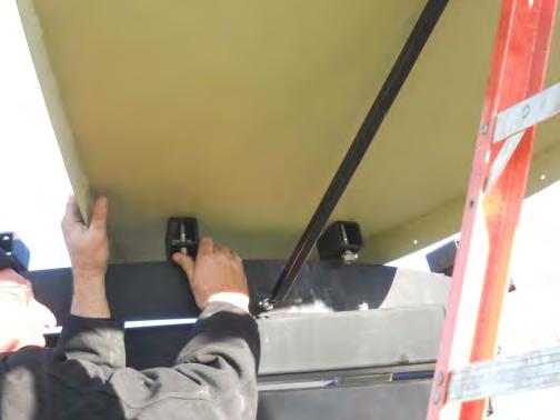
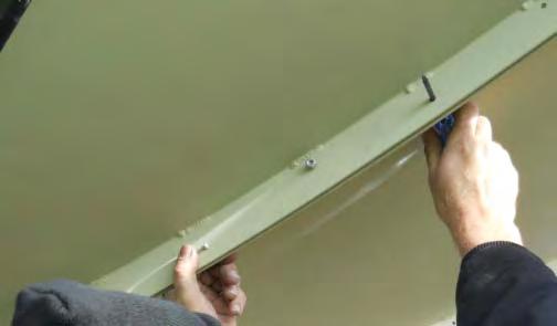
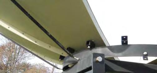
8 Installation Photos: Additional Help for Installing by Sections to the Ring Template Rib Color Coded Dot on Rib Back Brace Tab Block Continue to page 6B for section by section installation
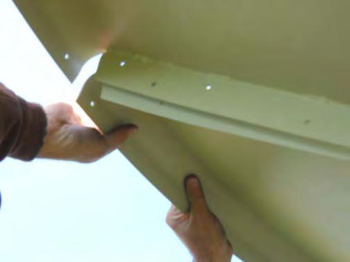
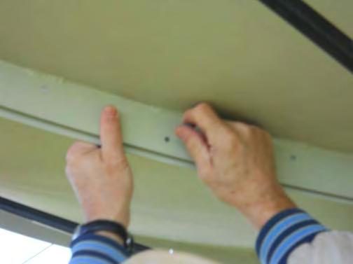

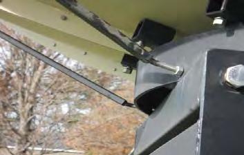
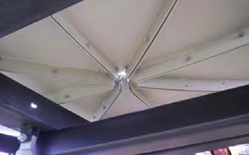

9 Installation Photos: Additional Help for Installing by Sections to the Ring Template Rib Splice Strap Back Brace Brace Clip Continue to page 6B for section by section installation


.")

.")

.")

 Once secure you can begin bolting the two units together by placing the ¼ x ¾ bolts through the templates.")
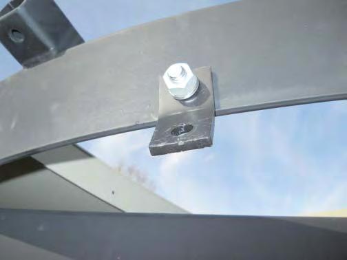
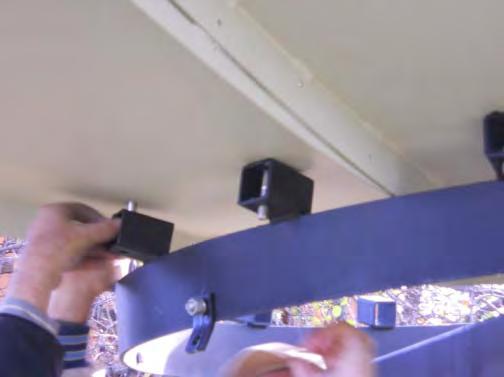
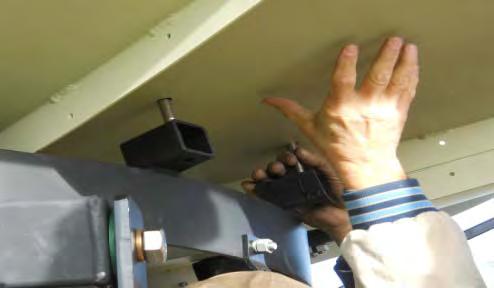
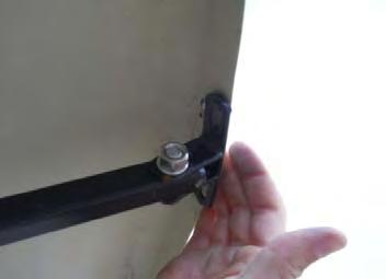
10 OPTIONAL ASSEMBLY METHOD (Install By Sections: Using 2-3 People) Assemble mount and put mount in birdbath position. Be sure to lock the mount with ratchet straps once in birdbath position. (See picture C, birdbath below) Step 1: Install the brace clips to the back braces before placing on the antenna lip and ring. Have all 8 brace clips installed on the brace before going to the next step. See brace clip and back brace photos below. Step 2: Install brace clips to the ends of the 8 back braces and install the ½ nut on the threaded rod end of the back brace, threading it down approximately 4 to 4 ½ down the threaded rod (see FIG. #13 and #14). Step 3: Take the first panel and install it to the ring of the mount finger tight. Be sure to find the pilot hole on the mount and on the antenna. Take the back brace that is ready and put the threaded rod through the tab on the ring (see photo A). Take the other end of the rod with the clip and attach the brace and clip to the lip of the antenna section (see picture B). Step 4: Insert ½ x 3 bolt (see FIG. #17 for washers and rubber placement) from the antenna to the mount. Have one person continue holding the panel in place while the second person attaches the back brace. (Remember the threaded end of the back brace should already have the ½ nut on the threaded end about 4-4 ½ on the threaded rod and the bent tab already installed on the ring, see FIG. #15). Insert the threaded rod of the back brace into the bent tab and bolt brace clip on the edge of the antenna with 3/8 x 1 ½ bolt, 3/8 nut and 3/8 lock washer. Make sure everything is finger tight. Step 5: Pick up the second antenna panel and be sure the numbers line up and bolt in place just like the first panel. (see FIG. #9) Once secure you can begin bolting the two units together by placing the ¼ x ¾ bolts through the templates. Again only finger tight. Continue for the next 6 panels. STEP 6: You will notice all 8 bolts in the face of the antenna have been installed from the antenna to the ring at his point. You now remove every other bolt from the face of the antenna and replace them with a feed strut. (See preparing the feed assembly on page 10) FIG. #13 Brace Clip FIG. #15 PICTURE A 60 Ring 1/2 x 1 1/2" Bolt Back braces are measured by tube length only. PICTURE AA PICTURE B Brace Tab Threaded Block 1/2 x 3 Bolt FIG. #17 PICTURE C Match 2 with 2 FIG. # 9 Page 6B
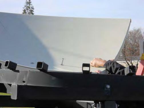
11 ASSEMBLING THE ANTENNA TO THE RING This section/page is for assembly of a 1pc solid antenna or a sectional antenna assembled to install as a 1pc antenna. (3M-4.5M) The mount should be assembled and now it is time to install the antenna. We recommend two methods of lifting the antenna onto the post. The first option is using the Ground method. Place the antenna face down and with a person under the antenna, you will place the ring on the antenna. Put the bolt from under side up through the dish and ring tabs. Attach the 8 back braces, clips, and tabs on the ring and tighten, but not too tight as we need to allow for flex. You can now lift this antenna and ring by a crane, forklift or a boom truck. This insures that no pressure will be put on the antenna. The second option is the Bird Bath method. If you are going to use manpower, follow the ensuing instructions. First you must elevate the ring to about 60 degrees. Lock it in place. Now locate the 1/8 pilot holes on the ring and the antenna. One is located next to one of the 16 ½ holes in the dish and the other is located on one of the 16 blocks next to ½ holes on the mount. See figure #5. (These pilot holes are only to locate the two 1/2 holes they will not line up from the mount to the dish.) When you have located these two holes, use 4-5 people and pick up the dish and set it into the ring making sure the pilot holes line up. BE EXTREMELY CAREFUL IN HANDLING THE ANTENNA WHEN SETTING IT INTO THE MOUNT. Now slip in the 1/2 x 3 bolts, (leave out every fourth bolt when using a C, Ku, C/Ku, or S band feed.) Do not tighten these bolts more than just snug. Now put the dish in a very flat position (birdbath). Have the smallest worker (installer) get into the dish and install the feed and hold the bolts while they are tightened. Install the bolts as in figure #6. DO NOT OVER TIGHTEN. Figure #5 Figure #6 FRONT VIEW STD AZ-EL Note: THE WELD OF THE ANTENNA IS ALWAYS LINED UP WITH THE BOOM OF THE MOUNT *FROM THE BACK VIEW OF ANTENNA Pilot hole is located on the 2 nd block from the left of the weld on the ring. Page 7
12 Assembling & Installing the Back Brace---- There are eight holes around the rear of the 60" ring to accept the braces. First install the bent tabs (See Figures #7 & #8). The bent tabs are a piece of steel bent in the middle, approximately 1 ½ x 3" long with two holes; you will find these in the bolt bag. Fasten the bent tabs with ½ bolts to the 60" ring, thread one ½ nut about 2/3 of the way down on the 2/3 rod end of the brace. Slip the rod end thru the tab and install another 1/2" nut. Only tighten these finger tight. Go to the edge of the dish and place the two 1/4" x 3/4" bolts thru the dish and into the end of the brace clip and tighten with 1/4" nuts. Fasten the end of the back brace to the brace clip using 3/8 x 1 ½ bolt and 3/8 locknut. (Refer to Figure #5 on pg. 6) Repeat this on all eight braces on the 3.7m, 3.8m, 3.9m, 4.2m, 4.5m and 5.0m antenna. Set the dish in its normal position for tracking the arc and walk 30 feet away and sight the front surface of the dish. It should be flat. If it is not, adjust any braces that may be holding pressure and try to make the front surface flat. Try to do very little adjusting and try to release pressure to make flat. String the antenna in four locations is advised. String from back brace across the face of the antenna to the diagonally located brace. Adjust so that the strings just touch in the center. The following is a list of the different back braces for the different size antennas. Check this chart to be sure you have the right length braces. Listed is tube length only and does not include the bracket or the bolt in this measurement. Refer to Figure #9. Dish Size Focal Length Tube Length 10' (3.0m) 36 f/l None 11' (3.3m) 36 f/l 40 Discontinued 12' (3.7m) 57.6 f/l (3.8m) 57.6 f/l 47 12' 9" (3.9m) 57.6 f/l 50 Discontinued 14' (4.2m) 57.6 f/l 55 ½ Page 8
.")
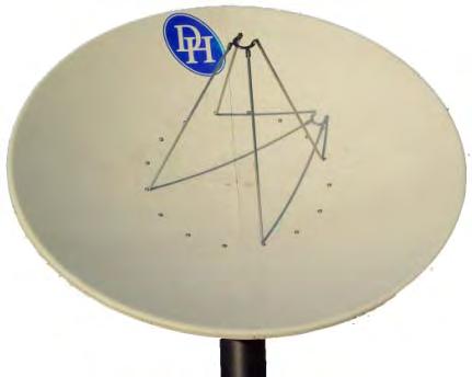
13 Fine Tuning the Antenna To get the most gain from your antenna, take an extra hour to make the adjustments needed and if possible use a Spectrum Analyzer. You will be able to see your increase or decrease gain with each adjustment you make. To begin, string the antenna (use two strings on 3.3m and four strings on antennas 3.7m and larger). You do this by simply taking a string and tying it to one brace and running the string across the front of the antenna to the other brace at 180 degrees, tying it so it is taut. Tie another string to a brace 90 degrees from the first brace and run it to the corresponding brace 180 degrees away. Be sure you put the string on top or under the other string so they do not touch each other. You should, when done, have two/four strings at 90 degrees and they should meet in the center of the antenna. If the strings don't touch at the center, then you will have to do some adjusting with the braces. BE SURE YOUR STRINGS ARE TAUT. Stand back about 30 feet and sight the antenna to see where you must apply pressure with the braces or relieve the pressure from another area. Go ahead and make small adjustments with the braces, each time checking with the Spectrum Analyzer to see that you are increasing the gain of the antenna. Elevation Fine Tuning The fine tune adjustment for the elevation of the AZ-EL Mount is very simple to operate. First elevate the antenna to the satellite and lock the elevation rod down. Tighten the U- bolt on the tube and loosen the bolts on the bracket that hold the tube. The tube now can be moved up and down by loosening and tightening the nuts on either side of the bracket. You can make very small adjustments with this bracket, thus optimizing your signal. Page 9

14 Preparing the C Band Feed Assembly If the feedhorn you have selected has an adjustable scalar ring, move it to the proper wave guide setting as per the manufacturer's instructions. Below we have listed the focal lengths and focal length diameter ratios for our commercial antennas. Just find your antenna and you will have the information to set the scalar properly. Special Note: More critical than setting the wave guide to the manufacturer's recommendations is to make sure you are setting the feedhorn at the correct focal length of the antenna. Antenna Size Focal Length Focal Distance 10' (3.0m) 36" f/l.3 f/d 11' (3.3m) 36" f/l.27 f/d Discontinued 12' (3.7m) 57.6" f/l.4 f/d 12 5 (3.8m) 57.6 f/l.378 f/d 12' 9" (3.9m) 57.6" f/l.375 f/d Discontinued 14' (4.2m) 57.6" f/l.35 f/d 14' 9" (4.5m) 57.6" f/l.33 f/d Not available with az-el 16' (5.0m) 57.6" f/l.3 f/d Not available with az-el NOTE: Strut length includes bent end. Your DH representative should have asked you what type feed you will be using. We need this information to be assured we are sending the proper collar to attach your feed to our struts. In the event that DH did not get this information a standard strut/collar (c14f) is sent. Take the collar and set it on the back of the scalar ring of the feedhorn. Turn it until all three holes line up between the two and insert the 1/4" x 3/4" bolts through the scalar ring and then thru the collar; fasten with the 1/4" nuts. Most C-band and dual feeds have a 3-bolt pattern on the scalar ring as described above. For heavy duty SEAVEY (C24HD) or heavy duty CHAPARRAL (C14FHD) feed assembly please refer to page 11 and page 12. For CHAPARRAL type feeds, refer to Figure #10. Slip the feed strut into a tab on the collar and line up the two holes. Insert the 2 ¼ x 1 ½ bolts into the holes and tighten with the 1/4" nuts. Proceed with all four struts then check focal length and tighten down. Use every third hole. The actual focal length should be 1/4 inside the waveguide for C-band and 1/8 for Ku band. 1/4 x 1 1/2 Bolt Collar Figure # 10 C14F 1/4 Lock Washers & Nuts 1/2" x 3 Bolt 3/4 Feed Strut 1/2 Rubber Washer Antenna Surface 1/2 Steel Washer 1/2 Nut (For use of Chaparral (Universal) Feed) Page 10

15 Heavy Duty Feed Strut We have developed a new feed strut and collar for the heavier 4 Port Seavey and Chaparral feed assemblies. This utilizes the rectangular aluminum tube for the feed strut. Refer to the drawing on page 12 for the bolt placement of a C14FHD or C24HD. Each strut has 2 5/16 x 2 ¼ bolts to attach to the feed collar. Attach one of the angle brackets (2" x 2") to the antenna with the ½ x 3 bolts. Notice that angle brackets have two holes. The bottom hole is for a Seavey type feed (C24HD). The top hole is for a Chaparral type feed (C14FHD). Next, attach the base of the strut to the angle brackets with the 5/16 x 1 ½ bolts supplied. Align the feed to point directly at the center of the antenna. Measure the focal length to the front of the scalar rings. (Seavey recommends f/l is measured to front of scalar ring.) (Chaparral measures ¼ inside the wave guide.) Ku Band Feed Assembly When using the Ku only feeds, you will be using the C14F feed plate and tri collar. See Figure #13. First, attach the flat tri collar to the feedhorn as follows: attach the first two pieces by using the 8 32 x 1" screws provided. Now slide the collar onto the feedhorn and add the third piece; tighten evenly. Attach the tri collar to the larger horseshoe collar by the 8 32 x ¾ bolts and nuts; tighten down. You can adjust polarity by loosening these nuts and rotating feed. Finish by assembling the struts to the feed collar as shown in Figure 14. (Fig#14 shows single Ku feed inserted in collar) Figure #13 Figure #14 Fine Tuning the Antenna After the assembly is complete, we recommend you "string the antenna." Simply run a string from a back brace across the front of the antenna to the brace 180 degrees apart. Now do this with each brace. If the strings all meet in the middle and no pressure is on any of them, the antenna is perfect and no further work needs be done. If one of the strings is not close to the others, then step back and sight across the dish and see where you will have to push with the back braces. Only make small adjustments at a time and remember to start with all braces loose. After you are sure the antenna surface is flat, you should double check to see that the feedhorn is set at the proper distance, then check to see that it is pointed at the center of the antenna. In our years of setting up antennas, these three items seem to cover over 98% of all problems of picture quality (See also page 13). Page 11
16 Notes This strut is used for 60" mount with: HD Feed collar Use the 2 holes on the strut for the C14HD or C24HD Bolt goes through the 1-1/2" side of the feed strut 3/8" 11/32" Hole 60" MOUNT Use this end to fasten to feed collar 1 3/4" 7/8" 1" 11/32" Holes Use this end to fasten to bracked on dish FOR ANTENNAS: 3.7m, 3.8m, 4.2m, 4.5m, 5m use 59"x1"x1.5" struts FOR 3 METER Antenna use 39"x1"x1.5" struts 1 1/2" C14F-HD or C24HD C14F-HDC24HD COLLAR 5/16" x 2 1/4" Bolts Feed Struts Top hole is for Chaparral type feed 11/16" Hole Bottom hole is for Seavey type feed 17/32" Hole 5/16" x 1 1/2" Bolt 1/2" x 3" Bolt Antenna 2" x 2" Angle Brackets DESCRIPTION: DRWN BY: SCALE: DH SATELLITE P.O. BOX 239 PRAIRIE DU CHIEN, WISCONSIN PHONE (608) FEED ASSEMBLY FOR C14F-HD & C24HD 60" RING MD/GILBERTS DATE; REVISED: NOT TO SCALE DRWG#: C14HD feed for 60ring


 or to make a tool to assist in finding the center of")
17 ADDITIONAL FINE TUNING TECHNIQUES To receive the optimum from your antenna, you must take time to fine tune the antenna. What are the antenna adjustments? They are: make the front surface flat, be sure the feed looks at the center of the dish, and set the proper focal length. You must also be pointed at the satellite and have the feedhorn skew properly adjusted. Many of the adjustments are done without any measurement of the signal, and in fact require no signal at all. The adjustment of making the front surface flat, adjusting the focal length, and aligning the feed will be done without signal. You will use the strings and the back braces to make the dish flat, a focal finder and measure tape to align the feedhorn to find center, and set the focal length using a measure tape to measure from dish to feedhorn. You will use a satellite tool to locate signal in further steps of fine tuning. We feel that you must use strings to assure the front of the dish is flat. The strings must be taut and run from brace to the opposite brace at 180 degrees. A larger dish with 8 braces needs four strings. Do all adjustments with the braces loose. The strings must touch at the center, if they do not, sight the dish from the side to see which braces should be slightly adjusted to make the front surface of the antenna perfectly flat. CAUTION: do not over tighten the 12 bolts that hold the dish to the ring as they can distort the dish. The easiest way to assure yourself that the feedhorn is looking directly at the center of the antenna is to use a Focal Finder (SEE PHOTO A BELOW) or to make a tool to assist in finding the center of the antenna. You can if no focal finder is available, cut a 1 X 4 board to the length of the antenna s focal length. Held vertically against the feed it should point at the center of the antenna, this will be true at the horizontal plane as well. DH recommends using an A1 Turbo S2 made by Applied Instruments or another tool such as a spectrum analyzer to locate your satellite signal in order to complete the following steps: Setting the Azimuth: To set the azimuth of the system you will use the base can and a tool to locate and measure signal. Find a satellite signal using the A1-Turbo or another satellite tool that will show signal spiking. Any signal strength will work. This is your reference point. Now you will go from bad signal to bad signal. From this reference point you will move the antenna left of the reference point to see if the signal gets better or worse and right of the reference point to see if this makes it better or worse. When you see the location of the base can for the best signal, you will tighten down the set screws on the base can. (Special Note: It is best to make a mark on the pole and base can to reference your starting point before making any moves with the base can. Remark your base can and pole so that you now know the location that is allowing the strongest satellite signal.) Setting the Elevation: You will use the turnbuckle assembly to make this adjustment and again you will go from bad to bad signal and find the center point with the best signal strength. Again, to make this adjustment you will only use the turnbuckle. It is best to mark the starting point of the threaded rod or count the turns so you know exactly where you started before making slight adjustments with the turnbuckle assembly. Skewing the feedhorn: You will rotate the feedhorn again going from left or right of the marked reference location for your feedhorn to find your strongest signal. Once you find your strongest signal tighten down into place. Keep in mind when you are making these last Additional Fine Tuning Techniques very small moves will be needed to make the best improvements in signal strength. PHOTO A Focal Finder to Locate Center of Antenna A1 Turbo S2 Made By Applied Instruments Page 13
 20-1/4 x 3/4\" Bolts 20-1/4\" Nuts 20-1/4 Lock Washers Ku4FL: 3PC ADD TO C14F 3- Section to 3pc collar 3 8-32 x 1 Bolts 3pc Collar To Horseshoe 3 8-32 x ¾ Bolts 3- #8")
 2-3/4 x 3 Bolts 2-3/4 Nuts 2-3/4 Lock Washers Antenna to")


18 BOLT BAG FOR: THE STANDARD AZ-EL MOUNT C14F Feed Assembly 1- Set of 4 Struts 1- Collar (C, Ku) 8-1/4 x 1 1/2 Bolts 8-1/4 Lock Washers & Nuts Feedhorn to Collar & LNB 3-1/4 x 3/4" Bolts 3-1/4" Lock Washers 3-1/4" Nuts (LNB to Feed) 20-1/4 x 3/4" Bolts 20-1/4" Nuts 20-1/4 Lock Washers Ku4FL: 3PC ADD TO C14F 3- Section to 3pc collar x 1 Bolts 3pc Collar To Horseshoe x ¾ Bolts 3- #8 Fender Washers Nuts Heavy Duty Feed Struts C14F or C24 1- Set of 4 Struts 1- Collar (C, Ku) 12-5/16 Lock Washers & Nuts 4-2' x 2' Angle Brackets 4-5/16 x 1 ½ Bolts 8-5/16 x 2 ¼ Bolts Base Can to Mount 2-3/4 x 5 Bolts 2-3/4 Nuts 2-3/4 Flat Washers 2-3/4 Lock Washers Elevation Assembly 1- Elevation Clamp 1- Elevation Tube (36 Long) 2-3/4 x 3 Bolts 2-3/4 Nuts 2-3/4 Lock Washers Antenna to Ring (16 Block) 16- ½ x 3 Bolts 16- ½ Flat Washers 32- ½ Rubber Washers 16- ½ Lock Washers 16- ½ Nuts Fine Tuning Kit 1-5/16" x 2 U-bolt 2-5/16" Lock Washers & Nuts 1-3 x 2 x 2 Elev. Angle 1-5/8" x 8" Eye Bolt 2-5/8" Nuts 1-1/2" x 1 1/2" Bolt 1-1/2" Nut 1-1/2" Lock Washer Back Braces 8- Back Braces 8- Brace Clips 8- Bent Tabs 8- ½ x 1 ½ Bolts 24- ½ Nuts 8- ½ Lock Washers 8-3/8 x 1 ½ Bolts 8-3/8 Nuts 8-3/8 Lock Washers 16- ¼ x ¾ Bolts 16- ¼ Nuts 16- ¼ Lock Washers Back Brace Length 3.7m- 45 Long 3.8m- 47 Long 4.2m- 55 Long 4.5m Long NOTE: SECTIONAL ANTENNAS INCLUDE ADDITIONAL HARWARE, SEE TABLES BELOW Template Rib Hardware: Sectional Antenna Size ¼ x ¾ Bolts ¼ Lock Washers ¼ Nuts 3.0M M M M M Splice Straps: Sectional Antenna Size Splice Straps ¼ x ¾ Bolts ¼ Lock Washers ¼ Nuts 3.0M M M M M If you have upgraded to an 8PC 3.7M sectional antenna please refer to the tables below for additional hardware needed. Base can with set screws. NOTE: Stainless steel or DURA-CON hardware provided. *DURA-CON is a corrosion resistant coating. DURA-CON : Problem of thread-galling is eliminated. Template Rib Hardware: Sectional Antenna Size ¼ x ¾ Bolts ¼ Lock Washers ¼ Nuts 3.7M Splice Straps: Sectional Antenna Size Splice Straps ¼ x ¾ Bolts ¼ Lock Washers ¼ Nuts 3.7M Page 14

19 MISSING PARTS WARRANTY You have obtained one of the best antennas on the market today! We hope that you will be happy with your new DH Antenna. To better acquaint you with our system, we ask that you read the instruction manual and verify that all of the equipment has been supplied in your shipment. Please check the hardware as well as the parts list and compare to what you have received. It is our policy to make every effort to assure you that you have received all parts necessary to make this a pleasant experience. While checking over your parts it is possible to find that you are missing pieces that are necessary to complete the installation. You will find below our shipping policy and charges if any. Notify Factory within 5 days ARO (Delivery): Red / no charge Notify Factory 5 to 30 days ARO: Regular / no charge Notify Factory 31 days ARO: Your cost for parts and shipping. Please note we are only able to ship out from our location if notified by 12:00 PM CST. Calls received after this time will ship the following business day. Call us M-F 7:30 am to 5 pm PHONE: 1 (608) FAX: 1 (608) dhsat@mhtc.net Please make notes below to help in future years with replacement needs. Size of antenna: Feedhorn make: LNB Make: Mount type: Model: Model:
3.0M, 3.7M & 3.8M Antenna w/48 Polar Mount 1 PC or Sectional INSTRUCTION MANUAL
 3.0M, 3.7M & 3.8M Antenna w/48 Polar Mount 1 PC or Sectional INSTRUCTION MANUAL CONGRATULATIONS on obtaining your new DH Antenna and mount. The 48 polar mount has been designed with a 48 diameter ring
CRITICAL FACTORS INSTALLING A DH ANTENNA
 CRITICAL FACTORS INSTALLING A DH ANTENNA 1. READ INSTRUCTIONS before disassembling the crate. 2. RIBS: Look for color coded dot on the rib. Dots indicate correct order to assemble panels. Number is stamped
HANDLING AND ASSEMBLY INSTRUCTIONS FOR TRUE FOCUS 3.0M, 3.8M AND 4.2M ANTENNAS WITH POLAR MOUNT
 HANDLING AND ASSEMBLY INSTRUCTIONS FOR TRUE FOCUS 3.0M, 3.8M AND 4.2M ANTENNAS WITH POLAR MOUNT Introduction SECTION 1 Thank you for purchasing one of our fine True Focus products. This manual covers the
Before returning this product to the store of purchase
 Before returning this product to the store of purchase Contact Dee Zee if you experience the following problems: Missing Parts Installation Problems/Questions Warranty Questions 1.800.779.2102 Hours of
RBP-1215B-RX DODGE RAM QUAD CAB RX3
 RBP-1215B-RX3 2002-2017 DODGE RAM 15-3500 QUAD CAB RX3 Passenger side RX-3 Side Step Drill Template Passenger side rear Modular Bracket (6) L Support Brackets Driver side rear Modular Bracket Driver side
1.2 METER SERIES 1130 Rx/O ANTENNA SYSTEM
 REVISION H April 20, 2016 ASSEMBLY MANUAL 1.2 METER SERIES 1130 Rx/O ANTENNA SYSTEM General Dynamics SATCOM Technologies 1700 Cable Drive NE Conover NC 28613 USA Phone 770-689-2040 www.gdsatcom.com 1.2
Gared Pro-S Portable Backstop
 Models: 9616 & 9618 Installation, Operation and Maintenance Instructions Please read all instructions before attempting installation or operation of these units SAVE THESE INSTRUCTIONS FOR FUTURE USE PUBLICATION
.84M Ku-Band Rx/O Antenna System
 4096-644 Revision A May 9, 2003 ASSEMBLY MANUAL.84M Ku-Band Rx/O Antenna System PRODELIN CORPORATION 1500 PRODELIN DRIVE NEWTON, NC 28658 .84M Ku-Band Rx/O Antenna System A ORIGINAL RELEASE 5/9/2003 A.Hahn
Spring Loaded All Season Roll-Up Doors
 Spring Loaded All Season Roll-Up Doors STAND-OFF MOUNTING METHOD INSTALLATION INSTRUCTIONS READ THIS FIRST Carefully examine the crate(s) for damage before opening. If the carton is damaged, immediately
HD installation guide
 JANUS INTERNATIONAL 1 866 562 2580 www.janusintl.c o m 1950 1950HD installation guide RIGHT DRIVE END SHOWN LH OPPOSITE LEFT TENSION END SHOWN RH OPPOSITE PUSH-UP OPERATION 1950 1950HD SHOWN A rolling
GlideRite Retractable Cover System For HotSpring & Tiger River Spas (except Classic & pre-2000 Landmark Spas)
") List of Contents Quantity Description 12 #10 x 1 ½ Flat Head Phillips Screw (see pg. 2) 2 #10 x ½ Pan Head Phillips Screw (see pg. 2) 8 ¼ x 2 ½ Lag Bolt (see pg. 2) 7 ¼ 20 x 5 / 8 Hex Head Bolt (see pg.
List of Contents Quantity Description 12 #10 x 1 ½ Flat Head Phillips Screw (see pg. 2) 2 #10 x ½ Pan Head Phillips Screw (see pg. 2) 8 ¼ x 2 ½ Lag Bolt (see pg. 2) 7 ¼ 20 x 5 / 8 Hex Head Bolt (see pg.
400A 40113V, 401A 40120V, & 401AL 40120VL ALUMINUM VERTICAL 4000 LB LIFT INCLUDES SCREW LEG ASSEMBLY INSTRUCTIONS
 12/11/07 PAGE 1 OF 12 400A 40113V, 401A 40120V, & 401AL 40120VL ALUMINUM VERTICAL 4000 LB LIFT INCLUDES SCREW LEG ASSEMBLY INSTRUCTIONS Thank you for purchasing our product! *Please read these instructions
GlideRite Retractable Cover System For Hot Spot Spas (SE & SLX only)
") List of Contents Quantity Description 12 #10 x 1 ½ Flat Head Phillips Screw (see pg. 2) 2 #10 x ½ Pan Head Phillips Screw (see pg. 2) 8 ¼ x 2 ½ Lag Bolt (see pg. 2) 7 ¼ 20 x 5 / 8 Hex Head Bolt (see pg.
List of Contents Quantity Description 12 #10 x 1 ½ Flat Head Phillips Screw (see pg. 2) 2 #10 x ½ Pan Head Phillips Screw (see pg. 2) 8 ¼ x 2 ½ Lag Bolt (see pg. 2) 7 ¼ 20 x 5 / 8 Hex Head Bolt (see pg.
Spring Loaded SCREEN-PRO. All Season Roll-Up Doors IN-JAMB MOUNTING METHOD INSTALLATION INSTRUCTIONS READ THIS FIRST
 Spring Loaded SCREEN-PRO All Season Roll-Up Doors IN-JAMB MOUNTING METHOD INSTALLATION INSTRUCTIONS READ THIS FIRST Carefully examine the crate(s) for damage before opening. If the carton is damaged, immediately
1.8 METER SERIES 1194 ANTENNA SYSTEM
 January 14, 2002 REVISION G ASSEMBLY MANUAL 1.8 METER SERIES 1194 ANTENNA SYSTEM PRODELIN CORPORATION 1500 Prodelin Drive Newton NC 28658 1.8 METER SERIES 1194 ANTENNA SYSTEM G Revise Address 1/14/02 F
1.2M Ku-BAND Rx/Tx SERIES 1134 ANTENNA SYSTEM
 August 21, 1997 Revision D ASSEMBLY MANUAL 1.2M Ku-BAND Rx/Tx SERIES 1134 ANTENNA SYSTEM PRODELIN CORPORATION 1700 NE CABLE DRIVE CONOVER, NC 28613-0368 1.2M Ku-BAND Rx/Tx SERIES 1134 ANTENNA SYSTEM D
Assmann Corporation of America TANK INSTALLATION AND USE GUIDELINES FOR BULK STORAGE TANKS
 Assmann Corporation of America TANK INSTALLATION AND USE GUIDELINES FOR BULK STORAGE TANKS General Information Assmann polyethylene storage tanks are manufactured to give you the toughest, most reliable
6' Wide Premium Greenhouse Benches
 6' Wide Premium Greenhouse Benches Premium Greenhouse Bench with Stationary Top 2015 FarmTek All Rights Reserved. Reproduction is prohibited without permission. STK# DIMENSIONS 112416S6X08 6' W x 3' H
southpaw enterprises, inc.
 southpaw enterprises, inc. Store these instructions with the enclosed maintenance checklist in a safe place. You may also access them on our website. Instruction Sheet Wood Joist 2-1/2 Ft. Drop Ceiling
installation guide
 JANUS INTERNATIONAL 1 866 562 2580 w w w. j a n u s i n t l. c o m 2000 2500 3000 installation guide RIGHT DRIVE END SHOWN LH OPPOSITE LEFT TENSION END SHOWN RH OPPOSITE PUSH-UP OPERATION 2000 2500 3000
VIEWPOINT ALUMINUM RUNNING BOARD TOYOTA RAV4
 PARTS LIST: VIEWPOINT ALUMINUM RUNNING BOARD 1 Driver/Left Running Board 4 10-1.5mm x 50mm T-Bolt 1 Passenger/Right Running Board 12 10mm Plastic Retainers 1 Driver/Left Bracket 2 10-1.50mm x 40mm Hex
Installation Instructions Kit, Base Rail Bracket Part # 31413
 Installation Instructions Kit, Base Rail Bracket Part # 31413 Dealer / Installer: Provide a copy of these Instructions to the end user of this product. These Instructions provide important operating and
Oceanside Outdoor Vinyl Shower Kit (3 x 3 Enclosure)
") Oceanside Outdoor Vinyl Shower Kit ( x Enclosure) A B ASSEMBLY GUIDE REQUIRED FOR INSTALLATION (A) Zippity Post Extension for In-Ground Installation (Sold as 4-Packs) (B) Zippity Galvanized Steel Surface
Oceanside Outdoor Vinyl Shower Kit ( x Enclosure) A B ASSEMBLY GUIDE REQUIRED FOR INSTALLATION (A) Zippity Post Extension for In-Ground Installation (Sold as 4-Packs) (B) Zippity Galvanized Steel Surface
 INSTRUCTION BOOKLET #C0 Watch step by step installation instructions at: https://www.wallbedsbywilding.com/wallbed-installation-studio-series/ WARNING! ALL MURPHY/WALLBED SYSTEMS CONTAIN STORED ENERGY.
Horizontal Cable Systems
 ALUMINUM RAILING INSTALLATION INSTRUCTIONS Horizontal Cable Systems 1) Check Contents Of Packages: Verify that all parts have arrived and that they match the packing list. 1A) Coastal applications: Confirm
Flex Fence Instruction Manual
 The Safer Stronger Smarter Choice Flex Fence Instruction Manual Table of contents 2 3 4 4 5 5 6 7 8 10 10 11 11 12 13 13 15 18 18 19 20 22 Table of contents Supplies, tools and equipment Introduction Laying
INSPECTION AND CORRECTION OF BELLHOUSING TO CRANKSHAFT ALIGNMENT
 INSPECTION AND CORRECTION OF BELLHOUSING TO CRANKSHAFT ALIGNMENT BACKGROUND Proper alignment of the transmission input shaft to the crankshaft centerline is required in order to achieve the best results
INSTALLATION INSTRUCTIONS 3"/4 BENT END SIDEBARS FORD F-150 SUPERCREW PART # DZ /DZ
 INSTALLATION INSTRUCTIONS 09-12 FORD F-150 SUPERCREW PART # DZ 372697/DZ 372699 PARTS LIST: 1 Driver/Left Sidebar 4 1/2 Lock Washers 1 Sidebar 4 12mm x 32mm OD x 3mm Flat Washers 1 Driver/Left Mounting
1.8 METER SERIES 1184 ANTENNA SYSTEM
 REVISION F January 10, 2002 ASSEMBLY MANUAL 1.8 METER SERIES 1184 ANTENNA SYSTEM PRODELIN CORPORATION 1500 Prodelin Drive Newton NC 28658 1.8 METER SERIES 1184 ANTENNA SYSTEM F Revised Address 1/10/02
BISON GOOSENECK FOOTBALL 1 PAIR OF GOAL POSTS
 Instruction Manual BISON GOOSENECK FOOTBALL 1 PAIR OF GOAL POSTS Customer Service (800) 247-7668 P A R T S L I S T Item Qty Description Item Qty Description A 2 GOOSENECK POLE I 4 UPRIGHTS B 2 BAND CLAMP
Side Mount INSTRUCTION BOOKLET #C122 BED STYLE: PARK CITY
 Side Mount BED STYLE: PARK CITY INSTRUCTION BOOKLET #C1 WARNING! ALL MURPHY/WALLBED SYSTEMS CONTAIN STORED ENERGY. FAILURE TO USE AND FOLLOW THESE INSTRUCTIONS DURING THE INSTALLATION PROCESS COULD RESULT
Oxford Stalls Installation Instructions
 Oxford Stalls Installation Instructions RAMM Horse Fencing and Stalls 13150 Airport Hwy. Swanton, OH 43558-9615 1-800-434-8456 Rev. 8/15/17 Before You Start Typical stall sizes are 10 x 10, 12 x 12 or
Classic Roll Tarp. Installation Instructions. Attention Dealers: Please give this owners manual to the customer when the product is delivered.
 Serving the Truck & Trailer Industry Since 1944 Classic Roll Tarp Attention Dealers: Please give this owners manual to the customer when the product is delivered. Call 800-535-9545 www.aeroindustries.com
INSTALLATION INSTRUCTIONS 3 BULL BAR 99-04, 04 "HERITAGE" F-150/250LD 2WD, 97-04, 04 "HERITAGE" 4WD WD EXPEDITION/ WD EXPEDITION PART
 INSTALLATION INSTRUCTIONS 3 BULL BAR PART #B-F1971;B-F2971 PARTS LIST: 1 Bull Bar 2 12-1.75mm x 130mm x 40mm Hex Bolts 1 Driver/Left Mounting Bracket 4 12-1.75mm x 35mm Hex Bolts 1 Passenger/Right Mounting
MM540 Installation Instructions IMPORTANT SAFETY INSTRUCTIONS - SAVE THESE INSTRUCTIONS
 MM50 Installation Instructions IMPORTANT SAFETY INSTRUCTIONS - SAVE THESE INSTRUCTIONS Please read this entire manual before you begin. Do not unpack any contents until you verify all requirements on PAGE.
NOTE: Top section pole (Q) is packed INSIDE bottom section pole (S)
 is packed INSIDE bottom section pole (S)") Form 0905-0 Instructions and Parts List TM- Mini Castle (modified) MARTIN SAFETY SYSTEM NOTES: () A complete system is packed in two boxes post box and house box. House box contains hardware for both post
Form 0905-0 Instructions and Parts List TM- Mini Castle (modified) MARTIN SAFETY SYSTEM NOTES: () A complete system is packed in two boxes post box and house box. House box contains hardware for both post
Model 6025 Single-Boom
 Log Periodic FM Broadcast Antenna Model 6025 Single-Boom Instruction Manual Installation, Operation, & Maintenance Congratulations! Thank you for purchasing one of the finest FM broadcast antennas on the
.98M Ku-BAND Rx/Tx ANTENNA SYSTEM
 Revision C January 2, 2002 ASSEMBLY MANUAL ANTENNA SYSTEM PRODELIN CORPORATION 1500 Prodelin Drive Newton NC 28658 ANTENNA SYSTEM C Revised Series text B Revised Address 1/2/02 RAH A Revise and Update
TM12 ASSEMBLY INSTRUCTIONS
 TM12 ASSEMBLY INSTRUCTIONS Congratulations on purchasing the finest purple martin house available. Nature House Brand houses are the proven leader in aluminum martin housing for over half a century. After
Assembly Instructions 10 X 10 Aluminum Roof Support
 Assembly Instructions 10 X 10 Aluminum Roof Support Aluminum Roof Support Bolt Package 16-5/16 X 2 ¼ SS Bolt 24-5/16 X 1 SS Bolt 40-5/16 SS Nylon Lock Nuts 16-5/16 SS Flat Washers 28-4 ½ Wood Screws 36-1
ClearSpan End Frame Kit 30' Wide x 11' High
 ClearSpan End Frame Kit 30' Wide x 11' High Diagram shows the end frame kit for an end wall without a door. (Door and end panel are purchased separately.) Rafter and mounting feet shown in the above diagram
200A FLB VERTICAL 22113V LIFT W/CHAIN DRIVE WINCH
 PG. 1 OF 11 PORTA-DOCK, INC. 200A FLB VERTICAL 22113V LIFT W/CHAIN DRIVE WINCH STEP 1. Separate and group like parts and fasteners together. Locate the winch side member with the longer upright tube and
PACKING LIST MACO V-5000
 PACKING LIST MACO V-5000 PART QTY O.D. SIZE LENGTH DESCRIPTION CHECKLIST T47P 4 5/8.050 36 Aluminum Tubing _ T43P 1 7/8.050 48 Aluminum Tubing _ T18P 1 3/4.050 48 Aluminum Tubing _ T15P 1 5/8.050 48 Aluminum
 For Wallbed models: KING SIZE INSTRUCTION BOOKLET #C1 Watch step by step installation instructions at: https://www.wallbedsbywilding.com/wallbed-installation-studio-series/ WARNING! ALL MURPHY/WALLBED
ANTENNA EXPERTS. Website: AP MHz. 2.4 Meters 30dBi. Gain
 ANTENNA EXPERTS E-mail: info@antennaexperts.in Website: www.antennaexperts.in AP-180030 1700 1900 MHz. 2.4 Meters 30dBi. Gain INSTALLATION MANUAL GRID PARABOLIC ANTENNA NOTICE: Installation, maintenance
PORTABLE ADJUSTABLE BASKETBALL SYSTEM
 Instruction Manual PORTABLE ADJUSTABLE BASKETBALL SYSTEM P A R T S L I S T 5 1/2 and 8 safe play clearance Item Qty Description Item Qty Description A 1 Portable Base Assembly M 4 1/2 Lock Nut B 2 Front
Football Goal Posts MODEL SERIES: FGP400 and FGP600 series
 Football Goal Posts MODEL SERIES: FGP400 and FGP600 series Installation and Maintenance Instructions Please read all instructions before attempting installation of these units SAVE THESE INSTRUCTIONS FOR
ClearSpan End Frame Kit 26' Wide x 12' High
 ClearSpan End Frame Kit 26' Wide x 12' High Diagram shows the end frame kit for an end wall without a door. (Door and end panel are purchased separately.) Rafter and struts shown in the above diagram are
INSTRUCTION SHEET. PIECE INVENTORY - MOBILE BASES Refer to the diagram for part identification.
 INSTRUCTION SHEET D2260 HEAVY-DUTY MINI-MOBILE BASE D2057 HEAVY-DUTY MOBILE BASE D2058 SUPER HEAVY-DUTY MOBILE BASE D2259 EXTENSION KIT FOR D2260/D2057 D2246 EXTENSION RAIL KIT FOR D2058 This Shop Fox
INSTALLATION INSTRUCTIONS / DODGE RAM CREW CAB 2500/3500
 INSTALLATION INSTRUCTIONS 225019 / 225019-2 2010 DODGE RAM CREW CAB 2500/3500 PARTS LIST: Qty Description Qty Description 1 Driver/Left Side Bar 4 Plastic Square Retainer 1 Side Bar 2 12mm x 120mm Hex
INSTALLATION INSTRUCTIONS for the JOMY RETRACTABLE LADDER. If there are any questions, please call (800)
") INSTALLATION INSTRUCTIONS for the JOMY RETRACTABLE LADDER If there are any questions, please call (800) 255-2591 INSTALLATION INSTRUCTIONS WARNING! Ladder Sections Lock When Closed. Do Not Install or Close
INSTALLATION INSTRUCTIONS for the JOMY RETRACTABLE LADDER If there are any questions, please call (800) 255-2591 INSTALLATION INSTRUCTIONS WARNING! Ladder Sections Lock When Closed. Do Not Install or Close
Parts list continues on Page 2 HOUSE PARTS PACKED IN HOUSE BOX PARTS IN SMALL PLASTIC BAG (HARDWARE) POST PARTS PACKED IN THIS BOX (LARGE PLASTIC BAG)
 POST PARTS PACKED IN THIS BOX (LARGE PLASTIC BAG)") Form 05-07 Instructions and Parts List MSS- Martin Safety System NOTES: () A complete system is packed in two boxes post box and house box. House box contains hardware for both post and house assembly.
Form 05-07 Instructions and Parts List MSS- Martin Safety System NOTES: () A complete system is packed in two boxes post box and house box. House box contains hardware for both post and house assembly.
JK Front Crusher Flares
 INSTALLATION INSTRUCTIONS INST-17-03-030_A JK Front Crusher Flares IMPORTANT: Thank you for purchasing this Poison Spyder product. Please read through this entire document before proceeding with installation.
Nancy s Knit Knacks LLC 4 Yard Option Upgrade Kit Assembly Instructions and User Manual
 Nancy s Knit Knacks LLC 4 Yard Option Upgrade Kit Assembly Instructions and User Manual Thank you for purchasing our 4 Yard Option (4YO) Upgrade Kit. To install this upgrade you are simply going to assemble
Standard Pole Mount Parabolic Antenna Mounting Instructions 3 ft. (90cm) & 4 ft. (120cm)
 & 4 ft. (120cm)") 495 R Billerica Ave. N. Billerica, MA 01862 USA Tel: (978) 459-8800 Fax: (978) 459-3310 / 8814 www.radiowavesinc.com email: sales@radiowavesinc.com Standard Pole Mount Parabolic Antenna Mounting Instructions
495 R Billerica Ave. N. Billerica, MA 01862 USA Tel: (978) 459-8800 Fax: (978) 459-3310 / 8814 www.radiowavesinc.com email: sales@radiowavesinc.com Standard Pole Mount Parabolic Antenna Mounting Instructions
AUXILIARY FRAMING AND ACCESSORIES
 CUSTOM CABINETS & RACKS STRUT AND ACCESSO- RIES JUNCTION KITS ANGLE AND BRACE KITS SPLICE KITS BRACE KITS INSTALLATION KITS WALL ANGLE KITS RUBBER END CAPS SUPPORT INSTALLATION AND SUPPORT KITS STANCHION
HOUSE PARTS PACKED IN HOUSE BOX PARTS IN PLASTIC BAG (HARDWARE) PARTS IN SMALL PLASTIC BAG (FLOOR CLIPS) PARTS PACKED IN BUNDLE
 PARTS IN SMALL PLASTIC BAG (FLOOR CLIPS) PARTS PACKED IN BUNDLE") Check parts against this list before starting assembly. Refer to illustrations on pages 6 and 7 to view house parts. If any shortages are found, refer to Packing Slip for claim instructions. Item 3 5 6
Check parts against this list before starting assembly. Refer to illustrations on pages 6 and 7 to view house parts. If any shortages are found, refer to Packing Slip for claim instructions. Item 3 5 6
H HD Adult Wheelchair Swing Frame & Hangers(perm) IMPORTANT
 IMPORTANT") Page 1 IMPORTANT PLEASE READ THESE INSTRUCTIONS BEFORE COMMENCING ASSEMBLY. All equipment must be installed in accordance with these instructions. Check your shipment against Bill of Lading and Parts list.
Page 1 IMPORTANT PLEASE READ THESE INSTRUCTIONS BEFORE COMMENCING ASSEMBLY. All equipment must be installed in accordance with these instructions. Check your shipment against Bill of Lading and Parts list.
ALUMINUM FOOTBALL GOALS INSTRUCTIONS WARNING WARNING Upright. Upright. Flag. Flag. Offset Pole.
 ALUMINUM FOOTBALL GOALS INSTRUCTIONS 800-67-090 Flag Flag Ground Sleeve Anchor Kit WARNING Football goals are shipped unassembled. Read all instructions thoroughly before attempting to assemble this equipment.
Thank you for purchasing our product! *Please read these instructions and follow them step by step.*
 07/07/08.rev1 PAGE 1 OF 11 601AL VERTICAL 60120VL LIFT W/CHAIN DRIVE WINCH Thank you for purchasing our product! *Please read these instructions and follow them step by step.* Step 1. Separate and group
Classic Roll Tarp. Installation Instructions. Attention Dealers: Please give this owners manual to the customer when the product is delivered.
 Serving the Truck & Trailer Industry Since 1944 Classic Roll Tarp Attention Dealers: Please give this owners manual to the customer when the product is delivered. Call 800-535-9545 www.aeroindustries.com
INSTRUCTION BOOKLET #C21. For Wallbed models: KING SIZE
 For Wallbed models: KING SIZE INSTRUCTION BOOKLET #C1 WARNING! ALL MURPHY/WALLBED SYSTEMS CONTAIN STORED ENERGY. FAILURE TO USE AND FOLLOW THESE INSTRUCTIONS DURING THE INSTALLATION PROCESS COULD RESULT
TK 422 PORTABLE BRAKE
 1 TIN KNOCKER TK 422 PORTABLE BRAKE INSTRUCTIONS & PARTS DIAGRAM TAAG MACHINERY CO. (Master Distributor) 1257-B Activity Dr. Vista, Ca 92081 Tel: (800) 640-0746 Fax: (760) 727-9948 Website: www.tinknocker.com
Heavy Duty Ceiling Tilt Mount Installation Manual
 HD-CTM-5580 Heavy Duty Ceiling Tilt Mount Installation Manual *This Installation requires a minimum of two people. For your safety: Read the complete instruction manual before starting an installation
Paradigm. Connect100 Installation Guide
 Paradigm GX Connect100 Installation Guide Paradigm GX Safe Use WARNING Radiation Hazard. Transmitter power levels are sufficient to cause blindness or other serious injury to body tissue. Do not power
 INSTRUCTION BOOKLET #C10 Watch step by step installation instructions at: https://www.wallbedsbywilding.com/wallbed-installation-studio-series/ WARNING! ALL MURPHY/WALLBED SYSTEMS CONTAIN STORED ENERGY.
PowerLock. Installation Instructions. Attention Dealers: Please give this owners manual to the customer when the product is delivered.
 Serving the Truck & Trailer Industry Since 1944 PowerLock Attention Dealers: Please give this owners manual to the customer when the product is delivered. Call 800-535-9545 www.aeroindustries.com Indianapolis,
Kwik-Lock. Installation Instructions. Attention Dealers: Please give this owners manual to the customer when the product is delivered.
 Serving the Truck & Trailer Industry Since 1944 Installation Instructions Attention Dealers: Please give this owners manual to the customer when the product is delivered. Call 800-535-9545 www.aeroindustries.com
Horizontal Cable Systems
 ALUMINUM RAILING INSTALLATION INSTRUCTIONS v2012 orizontal Cable Systems 1) Check Contents Of Packages: Verify that all parts have arrived and that they match the packing list. 1A) Coastal applications:
10 x 10 Flat Top Two Tone Pergola
 0 x 0 Flat Top Two Tone Pergola Models: Bordeaux ASSEMBLY GUIDE OPTIONAL ACCESSORIES Arch Kit System ( Arches) Privacy Fence Panel System ( Panels & Middle Post) Bolt Down Bracket Kit ( for Pergola) Ver.0-00
Large Wood Windmill Assembly Instructions
 CROW S NEST (TOP VIEW) TOWER (SIDE VIEW) 0 QTY 2 2 ITEM QTY 2 QTY QTY 8 QTY 8 QTY 4 TOP TOP TOP 47 9 QTY 4 QTY 4 QTY 4 QTY 4 QTY 4 ITEM 6 ITEM 7 ITEM 8 ITEM 3 ITEM 9 ITEM 4 ITEM 2 ITEM 5 47 Leg QTY 4 42.5
PowerLock. Installation Instructions. Attention Dealers: Please give this owners manual to the customer when the product is delivered.
 Serving the Truck & Trailer Industry Since 1944 FOR Attention Dealers: Please give this owners manual to the customer when the product is delivered. Call 800-535-9545 www.aeroindustries.com Indianapolis,
Titan Series Assembly Instructions
 Titan Series Assembly Instructions Bill of Materials A(1) Vertical Post J(4) 5/8" Anchor Bolt B(1) Main Extension Arm K(4) Anchor Footing Rebar C(2) Parallel Linkage L(1) Anchor Footing Template D(1) H-Frame
Hardware and Components:
 Hardware and Components: (A) 5/16 x 2 Hex Bolt (B) 5/16 x 2-1/4 Hex Bolt (C) 5/16 x 2-1/2 Hex Bolt (D) 4X 5/16 x 3/4 Hex Bolt (E) 4X 5/16 x 1-1/4 Hex Bolt (F) 11X 5/16 Flat Washer (G) 12X 5/16 Nylock Nut
Tools: Sharpie, Square, Vise, Hack saw, Ruler, Punch, Hammer, File. 2. Cut the stock Place stock in vise and cut with hack saw
 Purpose: MAKE CATAPULT ARM Step 1 Tools: Sharpie, Square, Vise, Hack saw, Ruler, Punch, Hammer, File Materials: Flat aluminum ½ inch stock (see picture below) Gloves required 1. Pick up the aluminum ½
10 x 10 Arch Top Pergola
 0 x 0 Arch Top Pergola I N S T A L L A T I O N G U I D E O P T I O N A L A C C E S S O R I E S Privacy Fence Panel System ( Panels & Middle Post Included) Bolt Down Bracket Kit (Set of ) Additional Shade
3.8m Commercial Antenna TxRx King Post Mount
 ANTENNA SYSTEMS 3.8m Commercial Antenna TxRx King Post Mount INSTALLATION & ASSEMBLY INSTRUCTIONS LIMITED TWELVE (12) MONTH WARRANTY This PATRIOT ANTENNA equipment is warranted to be free from defects
12 x 12 Flat Top Pergola
 x Flat Top Pergola Model: Regency, Roosevelt A S S E M B L Y G U I D E O P T I O N A L A C C E S S O R Y Bolt Down Bracket Kit ( for Pergola) Ver./MAR 0 Ta b l e o f Co n t e n t s PAGE x Flat Top Pergola
PLAY HOUSE IMPORTANT
 IMPORTANT Page 1 PLEASE READ THESE INSTRUCTIONS BEFORE COMMENCING ASSEMBLY. All equipment must be installed in accordance with these instructions. Check your shipment against Bill of Lading and Parts list.
ClearSpan PolyMax Windbreak Wall
 ClearSpan PolyMax Windbreak Wall Photo may show a different but similar model. 2007 ClearSpan All Rights Reserved. Reproduction is prohibited without permission. Revision date: April 2007ldg STK# DIMENSIONS
Hoops Installation Instructions for Adjustable Basketball Goals
 WARNING! Before beginning any excavation, call your local Underground Service Locator company to make sure there are NO electrical power, natural gas, telephone, cable television, irrigation systems or
https://www.wallbedsbywilding.com/wallbed-installation-studio-series/
 For Wallbed models: KING SIZE INSTRUCTION BOOKLET #C1 Watch step by step installation instructions at: https://www.wallbedsbywilding.com/wallbed-installation-studio-series/ WARNING! ALL MURPHY/WALLBED
INSTALLATION INSTRUCTIONS GRILLE GUARD RAM 1500 PART # 5058/5058-2
 INSTALLATION INSTRUCTIONS GRILLE GUARD PART # 5058/5058-2 PARTS LIST: Qty Description Qty Description 1 Grille Guard 8 12-1.75mm x 35mm Hex Bolts 2 Upper Frame Mounting s (for trucks without tow hooks
INSTRUCTION BOOKLET #C20
 INSTRUCTION BOOKLET #C0 WARNING! ALL MURPHY/WALLBED SYSTEMS CONTAIN STORED ENERGY. FAILURE TO USE AND FOLLOW THESE INSTRUCTIONS DURING THE INSTALLATION PROCESS COULD RESULT IN SEVERE PERSONAL INJURY TO
Lok Fast Column Clamp General Information
 Lok Fast Column Clamp General Information Gates Lok-Fast Column Clamp Has These Advantages: Can Be Job Built Gang Formed No Loose Pieces Designed For Rapid Placement of Concrete Rapid Locking Action 3
SERIES M Ku-BAND Rx / Tx ANTENNA SYSTEM
 4096-432 June 15, 2011 REVISION D ASSEMBLY MANUAL SERIES 1125 1.2M Ku-BAND Rx / Tx ANTENNA SYSTEM General Dynamics 1500 PRODELIN DRIVE NEWTON, NC 28658 PRODELIN CORPORATION 4096-432 SERIES 1125 1.2M Ku-BAND
Baseball Backstopper System
 D 8 7 6 5 4 3 2 1 Baseball Backstopper System Cable Design - 4 Poles Layout Form Project Name: Zip Code: A2/A1 = D C B1/A2 = B2/A1 = C A2 POLE A1 POLE B A2/B2 = B1/A1 = B B2 POLE B1 POLE A Please fill
Assembly Instructions 10 X 10 Aluminum Frame Building
 Assembly Instructions 10 X 10 Aluminum Frame Building 27 97 9 8 47 36 74 52 10 10 X 10 Square Building W/ Dome Includes: The Steel Entry Door with a Dead Bolt Lock assembly and Aluminum Door Frame. Metal
12 x 12 Flat Top Pergola
 x Flat Top Pergola A S S E M B LY G U I D E Model: Freemont OPTIONAL ACCESSORY Bolt Down Bracket Kit ( for Pergola) Ver /NOV 00 AI-BP0-0- Ta b l e o f Co n t e n t s PAGE x Flat Top Pergola Introduction
Downtown Rack. Custom logo option available
 Custom logo option available Downtown Rack The Downtown Rack uses thick, square-tube construction that can t be cut with a pipe cutter. The extended width of the Downtown Rack makes for easy bike parking
INSIDE PANEL NOT SHOWN TO DETAIL ANCHORING SYSTEM
 SIX INCH ALPHA MODULE INSTALLATION KEWAUNEE SCIENTIFIC CORPORATION SIX INCH ALPHA MODULE ANCHORING SYSTEM After Alpha module has been set in desired location. Adjust the four adjustment bolts until the
10x10 Trellis Pergola
 0x0 Trellis Pergola ASSEMBLY GUIDE Ver.0-7 Table of Contents PAGE Introduction & Overview...................................................... Pergola Materials Overview..............................................................
CEILING-MOUNTED MONORAIL ANCHOR TRACK SYSTEM Assembly and Operation Instruction Manual
 CEILING-MOUNTED MONORAIL ANCHOR TRACK SYSTEM Assembly and Operation Instruction Manual This manual is for various mounting types and plain and trussed track profiles. ISO 9001:2008 Registered Manual 103-0075
Side-of-Pole Mount for 4 Modules (SPM4) For Module Type B ASSEMBLY INSTRUCTIONS. step-by-step assembly and installation
 For Module Type B ASSEMBLY INSTRUCTIONS. step-by-step assembly and installation") Side-of-Pole Mount for 4 Modules (SPM4) For Module Type B ASSEMBLY INSTRUCTIONS step-by-step assembly and installation Version 1, Rev A SP3358-2 PCN 060712-5 Side-of-Pole Mount for 4 Modules (SPM4) For
Side-of-Pole Mount for 4 Modules (SPM4) For Module Type B ASSEMBLY INSTRUCTIONS step-by-step assembly and installation Version 1, Rev A SP3358-2 PCN 060712-5 Side-of-Pole Mount for 4 Modules (SPM4) For
12 x 12 Flat Top Pergola
 x Flat Top Pergola Model: Freemont A S S E M B L Y G U I D E O P T I O N A L A C C E S S O R Y Bolt Down Bracket Kit ( for Pergola) Ver.-057 Ta b l e o f Co n t e n t s PAGE x Flat Top Pergola Introduction
(2) 12mm x 40mm Bolt Plate (long) pictured w/plastic retainer. (6) 12mm x 40mm Bolt Plate (short) Support Bracket Driver/left Front
 12mm x 40mm Bolt Plate (long) pictured w/plastic retainer. (6) 12mm x 40mm Bolt Plate (short) Support Bracket Driver/left Front") PARTS LIST: 1 Driver/left Running Board w-1 Backing 8 12mm Plastic Retainers 1 Passenger/right Running Board w-1 Backing 8 12mm x 32mm x 3mm Flat Washers 2 2 inch tall rubber backing (SX & Limited only)
PARTS LIST: 1 Driver/left Running Board w-1 Backing 8 12mm Plastic Retainers 1 Passenger/right Running Board w-1 Backing 8 12mm x 32mm x 3mm Flat Washers 2 2 inch tall rubber backing (SX & Limited only)
FLIP TARP SINGLE & DOUBLE UNDERBODY TRAILERS
 1-800-248-7717 1002 N. 15th Street, Middlesboro, KY 40965 FLIP TARP SINGLE & DOUBLE UNDERBODY TRAILERS INSTALLATION INSTRUCTIONS Congratulations on your purchase of a Mountain Flip Tarp Trailer system.
STANDARD GRAVITY BOX TARP INSTALLATION
 OPERATORS MANUAL Rev. 9.9.2016 STANDARD GRAVITY BOX TARP INSTALLATION J. & M. Mfg. Co., Inc. 284 Railroad Street - P.O. Box 547 Fort Recovery, OH 45846 Ph: (419) 375-2376 Fax: (419) 375-2708 www.jm-inc.com
ALUMA-CLASSIC FENCE W1716 & W1720 INSTRUCTION MANUAL
 ALUMA-CLASSIC FENCE W1716 & W1720 INSTRUCTION MANUAL Phone: Phone: 1-360-734-3482 On-Line On-Line Technical Technical Support: Support: tech-support@woodstockint.com tech-support@shopfox.biz COPYRIGHT
8 x 8 Flat Top Pergola
 A S S E M B L Y G U I D E O P T I O N A L A C C E S S O R Y Bolt Down Bracket Kit Models: Mirage, Mandalay Ver 6/00 Ta b l e o f Co n t e n t s Introduction & Overview......................................................