QDV120 Operation and Pointing manual
|
|
|
- Buck Watts
- 5 years ago
- Views:
Transcription


1 QDV120 Operation and Pointing manual MPAD1 Plus OP E1 page 1
2 Contents Item Description Page 1.0 Health and Safety for Operators and Installation Staff Transit case Reflector/Mount/BUC/LNB QDV120 IP Terminal Unpacking instructions Antenna Assembly 6 Step 1 - Remove Case lid Step 2 - Remove case contents and layout in order Step 3 - Kingpost/AZ-EL Head to Leg Assembly Step 4 - Adjustable Stay Assembly Step 5 - Reflector Assembly Step 6 - Wind load Stay Assembly Step 7 - Feed Arm Assembly APPENDIX A Pointing with MPAD1 PLUS and ODU Modem Power ON the Modem (the modem will take 1-2 minutes for Boot up) 2. Polarization of Feed 3. Elevation - Initial Setting 4. Azimuth - Initial Setting 5. Azimuth Fine Adjustment 6. Antenna Pointing Procedure (peaking) 7. Setting the satellite orbital slot 8. Dip Switch Selection Chart 1 Polarization Chart Chart 2 Elevation Chart Chart 3 - Azimuth APPENDIX B Pointing with Birddog and IDU 26 APPENDIX C Spares and Accessories 28 OP E1 page 2


3 1.0 Health and Safety for Operators and Installation Staff Prior to installation, verify that the installation site and supporting structure have been investigated and found capable of withstanding all loads imposed by the proposed antenna system, equipment and personnel. It is highly recommended that a RISK ASSESMENT is carried out prior to the deployment to ensure the safe working area for everyone and the risks have been reduced. Working at Height a brief guide Risk Assessment a brief guide The TP100 has been designed as a no-tool assembly, this results in moving parts that could cause a finger trap. These are pointed out through-out this manual. Do not stand in front of the antenna whilst the system is operating. Do not look into the feed system whilst the system is operating. Due to the single case design the transit case is a 4-man lift OP E1 page 3


4 2.0 Transit case Reflector/Mount/BUC/LNB The QDV120 is has been designed so that all the outside elements of the IP terminal are transported in one robust case. Size: H1470 X W1300 X D450 Weight: 96kg Recessed locking over centre catches Locking/Rotating castors 4 Carrying Handles Internal foam for transport protection Note : Due to the single case design the case is a 4-man lift OP E1 page 4

")
5 3.0 QDV120 IP Terminal Unpacking instructions Case Contents 1 X 1.2M Reflector 1 X AZ/EL no-tools head 1 X King post 3 X Tripod legs and sand feet 3 X Tensioning stays 2 X Front feed arm supports 2 X Rear antenna supports 1 X Feed arm with BUC/LNB/Cables 1 X Accessories pack 1 X ODU Modem 1 X MPAD1 Plus (and cables) OP E1 page 5


6 4.0 Antenna Assembly Step 1 Remove Case lid Unlock over-centre catch Use lifting handle Remove case lid Step 2 Remove case contents and layout in order OP E1 page 6

7 Step 3 Kingpost/AZ-EL Head to Leg Assembly AZ/EL Head / Kingpost The AZ-EL head and the King post will be pre-assembled and requires no tools to assemble or operate. Terrain compensating Inclinometer Reflector interface points Elevation Fine adjust Azimuth Fine adjust Azimuth Course adjust Adjustable stay clamping points King post leg locations Leg Assemblies (X3) The leg assemblies are supplied complete and need no tools for assembly Adjustable stay locations Sand feet Sand feet securing pin Tripod leg Leg Pins (X3 Note: to secure the legs to the kingpost you will need the Leg Pins from the Accessories Pack OP E1 page 7
 onto the centre location of the Kingpost and fasten")
 Note:")
")
8 Leg Assembly to Kingpost Insert the tripod leg (and sand foot assembly) onto the centre location of the Kingpost and fasten with the Leg Pin. Repeat this for all three legs. Step 4 Adjustable Stay Assembly Adjustable Stay Pins (X6) Note: to secure the legs to the kingpost you will need the Adjustable Stay Pins from the Accessories Pack Adjustable Stay s (X3) OP E1 page 8


9 The stays have opposite cut threads on each eyed end, this will allow the stay to extend in length by simply rotating the centre rod Open the adjustable stay pin clip and push the pin through the hole in the tripod leg, captivating the stay. Then secure the pin with the spring clip. Repeat for all three legs. Repeat this process for the retainer lugs on the kingpost (X3) You are now ready to tension the tripod Rotate the main connecting rod until pressure is applied to the leg and the kingpost. Repeat three times Warning: DO NOT OVER TIGHTEN OP E1 page 9


 Bottom stud into holes OP-080316-E1")
10 Step 5 Reflector Assembly Place the top reflector securing studs (with thumb nuts attached) into the top EL Plate slots Top studs to top slots With the top studs engaged, locate the bottom studs into the elevation plate bottom captive holes and secure with thumb nuts (In Accessories Pack) Bottom stud into holes OP E1 page 10


11 Thumb Nuts(M8) Secure reflector Tighten evenly (no movement) Step 6 Wind load Stay Assembly The QDV120 has four wind stays per system, two short stays for the rear and two longer stays for the front feed arm Studs to push through reflector Rear Front OP E1 page 11


12 Place rear wind loading stay inside rear of the reflector. Push the stud through the reflector This will be used to fasten the front feed arm stay Using the thumb nuts from the accessory pack secure the rear stay onto the elevation plate (X2) Tighten the thumb screws Using the rear wind stay stud, locate the front feed arm stay onto the reflector. Using the thumb nut from the accessory pack loosely tighten NOTE: the front feed arm stay must be allowed to move OP E1 page 12


13 Repeat the process both sides of the antenna The reflector is now ready to accept the feed arm assembly Assembly Tip: Step 7 Feed Arm Assembly Make sure you attached the feed to the feed arm stays before you fix the feed arm to the base of the antenna Using the Thumb stubs (in Accessory Pack) loosely secure the feed arm stays to the feed carriage Repeat both sides of the feed carriage Offer the feed arm up to the underside of the reflector Secure in place with thumb stud Tighten all Thumb nuts so that there is no movement of the components. OP E1 page 13

14 The antenna is now ready for pointing OP E1 page 14


 Power ON/OFF Button Modem Booting Please Wait will")
15 Appendix A Pointing with MPAD1 PLUS and ODU Modem Alignment with the satellite is obtained by setting polarization, elevation, and azimuth angles which will be automatically displayed on the M-PAD1 Plus hand held unit. As a precaution/ backup, charts are provided in this manual to determine the values for your earth station antenna site. ΔL is the difference between the earth station antenna site longitude and the satellite longitude. Use ΔL and your earth station latitude to obtain polarization, elevation or azimuth setting 1. Power ON the Modem (the modem will take 1-2 minutes for Boot up) Power ON/OFF Button Modem Booting Please Wait will appear on the M-PAD1 Plus whilst the modem is booting OP E1 page 15
 2.")

16 Once the Modem has booted and the GPS has locked the M-PAD1 Plus will display a T-AZ & T-EL (the T standing for target angle). The target AZ & EL will be the position of the satellite from your location. The Polarisation will be displayed as Receive POL (i.e. this is the polarisation of the receive carrier coming from the satellite) 2. Polarization of Feed NOTE: you must know the Polarization you are receiving (Horizontal or Vertical, this will be given to you by your satellite operator) Loosen feed Horn clamp bolts and turn feed clockwise or counter-clockwise, depending on the value calculated by the M-PAD 1 Plus hand held device. Alternatively set the POL angle, east or west of the satellite as shown on Chart 1. OP E1 page 16


 Step 2.")

17 3. Elevation - Initial Setting The QDV120 is fitted with a pre-calibrated oil filled terrain compensation inclinometer (which is mounted on the Elevation Head. The inclinometer has been set to compensate for the offset of the reflector. The M-PAD 1 Plus will display the calculated elevation angle Course Adjust Fine Adjust Step 1. Release the top locking nut (could be brass or hand nut depending on model) Step 2. Rotate the locking nut to give rough travel required to move the reflector to desired elevation NOTE: You can manually move the reflector Step 4. Use the lower hand nut for fine adjustment Step 5. Secure the top locking nut NOTE: for peaking you will need to release the locking nut OP E1 page 17


18 4. Azimuth - Initial Setting The M-PAD 1 Plus will display the calculated Azimuth angle Azimuth refers to the rotation of the whole antenna around a vertical axis. It is the side to side angle. The QDV120 azimuth mechanism will allow you to loosen the main mount bracket and swing the whole dish all the way around in a 360 deg circle. By definition North is 0 deg, East is 90 deg, South is 180 deg and West is 270 deg. North can also be called 360 deg. Course Adjust Step 1. Release the locking levers (X2) one on each side Step 2. Release the four azimuth clamps on the bottom of the AZ/EL head. NOTE: these could be over centre clamps or hand nuts depending on model number Step 3. Set the look angle as denoted on the M- PAD 1 Plus by moving the reflector with your hand (using a compass) Step 3. lock off the reflector with lock levers (X2) NOTE: leave the X4 bottom clamps loose until final pointing OP E1 page 18

19 5. Azimuth Fine Adjustment Note: that you find a satellite by pre-setting the elevation accurately and then swinging the whole antenna boldly in azimuth till the signal locks up - so an approximate azimuth angle is normally sufficient. Inclinometer Elevation fine adjust nut Elevation locking nut Azimuth fine adjust nut Once the antenna is peaked then secure the X4 Azimuth clamps on the bottom of the AZ/EL head OP E1 page 19
 and then put the dish in the exact centre.")
 After setting the azimuth with the fine adjust, tighten the X4 locking clamps on the bottom of the AZ/EL")
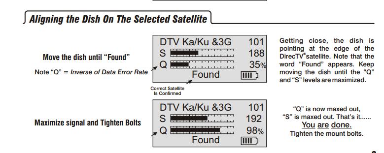
20 6. Antenna Pointing Procedure (peaking) Start with the azimuth direction and swinging the dish either side of the satellite till you lose the signal. You need to identify two points on either side where the signals are down by exactly the same amount (on your meter) and then put the dish in the exact centre. NOTE: on the M-PAD1 Plus the lower signal strength bar is the MAX signal strength that has been achieved, it will hold for a few seconds. This can be achieved by using the fine adjust lead screw on the AZ EL head (see section 5) After setting the azimuth with the fine adjust, tighten the X4 locking clamps on the bottom of the AZ/EL head. This locks the azimuth setting but will often simultaneously increase the elevation angle, so you may temporarily lose the signal. Elevation adjustment is best done with the bottom hand nut nut while allowing the weight to keep tight contact (no backlash). Count the turns while moving from one low measurement to the same low measurement. Then turn the nut accurately back to the middle position. Do it accurately to 1/6th of a turn by counting the knurls on the hand nut. Polarisation adjustment normally needs assistance from the network hub. The hub can switch your transmitter on and make it transmit a continuous wave (CW) un-modulated clean carrier on a frequency where it is unlikely to cause interference to other satellite services. Your antenna is ready to transmit. OP E1 page 20
 Remove the rear cover of the M-PAD1 Plus to expose the internal PCB.")

 POL X Circular (no polarisation")
21 7. Setting the satellite orbital slot The orbital slot can be set from -180 to +180 (- is locations West of South, + is for locations east of south) Remove the rear cover of the M-PAD1 Plus to expose the internal PCB. To adjust the orbital slot press the + and - input keys (reading on the front screen will change) once the desired orbital slot has been selected press the SAVE key 8. Dip Switch Selection The MPAD has a logic circuit to allow you to select linear or circular POL. Down UP EL X Elevation off set EL X Normal screen POL X Linear (Ku-Band) POL X Circular (no polarisation displayed on front LCD) 10 X Sets POL Mode to C0- POL (Vertical Rx pol = OP E1 page 21
22 0) 10 X Sets POL Mode to Cross- POL (Horizontal Rx pol = 0) A6 Not Used Polarisation mode selection Pin Mode : POL Down Linear UP Circular In the up position the MPAD2 will be set to circular polarisation, no POL skew angles displayed In the down position the MPAD2 will be set to linear polarisation, the POL angle for the desired satellite will be displayed on the front LCD for both Horizontal and vertical RX. Cross Polarisation mode selection Pin Mode : 10 Down Cross POL Vertical Rx =0 UP Co-POL Horizontal Rx =0 Pin mode 10 switches between H pol at 0 deg & V pol at 0 deg. Switch up is H at 0 which will relate to Co-pol on the 5W TRIA fitted and with the switch down it is V at 0 which will be Cross-pol for TRIA & normal operation for most beams. OP E1 page 22

23 Chart 1 Polarization Chart OP E1 page 23

24 Chart 2 Elevation Chart OP E1 page 24

25 Chart 3 - Azimuth OP E1 page 25
 OP-080316-E1")
26 Appendix B Birddog Pointing (Quick Start) OP E1 page 26
27 OP E1 page 27


 2 X Rear stay HOL0984 2 X Front stay HOL0985 Tripod")

28 Appendix C - Spares and Accessories Accessories Pack (Complete) Individual Part No. 3 X Leg Clips HOL X Adjustable Stay Clips HOL X Rear Stay Thumb Nuts HOL X Front to Rear Thumb Nuts HOL X Feed Support Stay Thumb Studs HOL X Antenna Securing Nuts HOL X Feed Arm to Reflector Thumb Stud HOL X Carry bag HOL0982 Tensioning stays (set) 3 X Tensioning stays HOL0983 Antenna stays (set) 2 X Rear stay HOL X Front stay HOL0985 Tripod leg (set) with sand foot 3 X Leg (with sand foot) HOL0986 MPAD1-PLUS Hand Held controller GPS Module Cables set HOL0987 HOL0988 HOL0989 OP E1 page 28
2005 ODU Point & Peak Job Aid
 Summary This Job Aid covers: Preparing the Antenna for Pointing and Peaking Point Elevation Set the Skew Point Azimuth Peak Azimuth Peak Elevation Push/Pull Test This Job Aid supports all Technician audiences.
C-COM Satellite Systems Inc. Page 1 of 39
 Page 1 of 39 inetvu Fly-75V & Fly-98G/H/V & Fly-981 User Manual The inetvu brand and logo are registered trademarks of C-COM Satellite Systems, Inc. Copyright 2006 C-COM Satellite Systems, Inc. 1-877-iNetVu6
Paradigm. Connect100 Installation Guide
 Paradigm GX Connect100 Installation Guide Paradigm GX Safe Use WARNING Radiation Hazard. Transmitter power levels are sufficient to cause blindness or other serious injury to body tissue. Do not power
75 cm ODU (VS1300) Assembly Job Aid
 Assembly Job Aid") Summary This Job Aid covers: Verify AZ/EL Assembly Alignment Antenna Back Bracket Assembly Transport On Site Assembly This Job Aid supports all Technician audiences. This job aid covers the VS1200 ODU
Summary This Job Aid covers: Verify AZ/EL Assembly Alignment Antenna Back Bracket Assembly Transport On Site Assembly This Job Aid supports all Technician audiences. This job aid covers the VS1200 ODU
2009 ODU Point and Peak Job Aid
 Summary This Job Aid covers: Preparing the Antenna for Pointing and Peaking Point Elevation Set the Skew Point Azimuth Peak Azimuth Peak Elevation Push/Pull Test This Job Aid supports all Technician audiences.
75 cm ODU (VS1300 with the SurfBeam2 TRIA) Assembly Job Aid
 Assembly Job Aid") Summary This Job Aid covers: Verify AZ/EL Assembly Alignment Antenna Back Bracket Assembly TRIA, TRIA Bracket, and Boom Arm Assembly This Job Aid supports all Technician audiences. This job aid covers
Summary This Job Aid covers: Verify AZ/EL Assembly Alignment Antenna Back Bracket Assembly TRIA, TRIA Bracket, and Boom Arm Assembly This Job Aid supports all Technician audiences. This job aid covers
1.8 METER SERIES 1184 ANTENNA SYSTEM
 REVISION F January 10, 2002 ASSEMBLY MANUAL 1.8 METER SERIES 1184 ANTENNA SYSTEM PRODELIN CORPORATION 1500 Prodelin Drive Newton NC 28658 1.8 METER SERIES 1184 ANTENNA SYSTEM F Revised Address 1/10/02
Assembly Manual for the 1.2m Quick-Deploy Antenna System
 704 North Clark Street Albion, MI 49224 USA Phone +1 517 680 0125 Fax +1 517 680 0133 www.challengercommunications.com Challenger Communications Assembly Manual for the 1.2m Quick-Deploy Antenna System
1.8 METER SERIES 1194 ANTENNA SYSTEM
 January 14, 2002 REVISION G ASSEMBLY MANUAL 1.8 METER SERIES 1194 ANTENNA SYSTEM PRODELIN CORPORATION 1500 Prodelin Drive Newton NC 28658 1.8 METER SERIES 1194 ANTENNA SYSTEM G Revise Address 1/14/02 F
75cm ODU/SurfBeam 2 Point and Peak Job Aid
 Summary This Job Aid covers: 75cm ODU/SurfBeam 2 Point and Peak Job Aid Preparing the Antenna for Pointing and Peaking Configure the SurfBeam 2 Modem and 75cm TRIA Point Elevation Set the Skew Point Azimuth
.98M Ku-BAND Rx/Tx ANTENNA SYSTEM
 Revision C January 2, 2002 ASSEMBLY MANUAL ANTENNA SYSTEM PRODELIN CORPORATION 1500 Prodelin Drive Newton NC 28658 ANTENNA SYSTEM C Revised Series text B Revised Address 1/2/02 RAH A Revise and Update
.84M Ku-Band Rx/O Antenna System
 4096-644 Revision A May 9, 2003 ASSEMBLY MANUAL.84M Ku-Band Rx/O Antenna System PRODELIN CORPORATION 1500 PRODELIN DRIVE NEWTON, NC 28658 .84M Ku-Band Rx/O Antenna System A ORIGINAL RELEASE 5/9/2003 A.Hahn
Instruction Manual for 98cm Elliptical Ka Antenna
 Instruction Manual for 98cm Elliptical Ka Antenna 98cm WB Issue 03 Caution This instruction leaflet will assist you in the correct installation of the product. Read it prior to starting any installation
MESA-HPX. Assembly and Installation Manual. w/appendix A for Prodelin Antenna. 901-Manual-MESA-HPX
 MESA-HPX Assembly and Installation Manual w/appendix A for Prodelin Antenna 901-Manual-MESA-HPX Rev 30 March 2011 2 INDEX Installation Cautions 4 Installation Pole Height Orientation of the Mount on the
1.2 METER SERIES 1130 Rx/O ANTENNA SYSTEM
 REVISION H April 20, 2016 ASSEMBLY MANUAL 1.2 METER SERIES 1130 Rx/O ANTENNA SYSTEM General Dynamics SATCOM Technologies 1700 Cable Drive NE Conover NC 28613 USA Phone 770-689-2040 www.gdsatcom.com 1.2
1.2M Ku-BAND Rx/Tx SERIES 1134 ANTENNA SYSTEM
 August 21, 1997 Revision D ASSEMBLY MANUAL 1.2M Ku-BAND Rx/Tx SERIES 1134 ANTENNA SYSTEM PRODELIN CORPORATION 1700 NE CABLE DRIVE CONOVER, NC 28613-0368 1.2M Ku-BAND Rx/Tx SERIES 1134 ANTENNA SYSTEM D
SERIES M Ku-BAND Rx / Tx ANTENNA SYSTEM
 4096-432 June 15, 2011 REVISION D ASSEMBLY MANUAL SERIES 1125 1.2M Ku-BAND Rx / Tx ANTENNA SYSTEM General Dynamics 1500 PRODELIN DRIVE NEWTON, NC 28658 PRODELIN CORPORATION 4096-432 SERIES 1125 1.2M Ku-BAND
ANTENNA EXPERTS. Website: AP MHz. 2.4 Meters 30dBi. Gain
 ANTENNA EXPERTS E-mail: info@antennaexperts.in Website: www.antennaexperts.in AP-180030 1700 1900 MHz. 2.4 Meters 30dBi. Gain INSTALLATION MANUAL GRID PARABOLIC ANTENNA NOTICE: Installation, maintenance
Installation Guide. Hiltron Motorized Antenna Mount HMAM
 HMAM_Install_A.doc Page 1 of 20 Installation Guide for Hiltron Motorized Antenna Mount HMAM HMAM_Install_A.doc Page 2 of 20 Table of Contents 1 Overview...3 2 Unpacking and Inspection...3 3 Contents of
SINCE 1922 P UBLICATION N O
 SINCE 1922 GARED SPORTS MICRO-Z SET-UP INSTRUCTIONS VERY IMPORTANT! READ INSTRUCTIONS CAREFULLY AND FOLLOW STEP BY STEP SET-UP PROCEDURE P UBLICATION N O. 5 5 1 7 5 2 9 1 6 Recommended tools and accessories.
MPA-9000 Universal Ceiling Projector Mount Kit
 I N S T R U C T I O N M A N U A L Universal Ceiling Projector Mount Kit The Universal Ceiling Projector Mount provides a unique, simplified method of ceiling mounting your inverted projector. This low
Gared Pro-S Portable Backstop
 Models: 9616 & 9618 Installation, Operation and Maintenance Instructions Please read all instructions before attempting installation or operation of these units SAVE THESE INSTRUCTIONS FOR FUTURE USE PUBLICATION
M2 Antenna Systems, Inc. Model No: 2MCP22
 M2 Antenna Systems, Inc. Model No: 2MCP22 SPECIFICATIONS: Model... 2MCP22 Frequency Range... 144 To 148 MHz *Gain... 14.39 dbic Front to back... 25 db Typical Elipticity... >3db Beamwidth... 38 Feed type...
HANDLING AND ASSEMBLY INSTRUCTIONS FOR TRUE FOCUS 3.0M, 3.8M AND 4.2M ANTENNAS WITH POLAR MOUNT
 HANDLING AND ASSEMBLY INSTRUCTIONS FOR TRUE FOCUS 3.0M, 3.8M AND 4.2M ANTENNAS WITH POLAR MOUNT Introduction SECTION 1 Thank you for purchasing one of our fine True Focus products. This manual covers the
Installation Guide Installation Kit for Mounting Philips MP20/30/40/50 on Datex-Ohmeda Aisys Anesthesia Machine
 Installation Guide Installation Kit for Mounting Philips MP20/30/40/50 on Datex-Ohmeda Aisys Anesthesia Machine The purpose of this guide is to: 1. Describe mounting of Counterweight (page 2). 2. Describe
1.2M Ku-BAND Rx/Tx SERIES 1132 ANTENNA SYSTEM
 August12, 2003 ASSEMBLY MANUAL Revision E 1.2M Ku-BAND Rx/Tx SERIES 1132 ANTENNA SYSTEM PRODELIN CORPORATION 1500 Prodelin Drive Newton NC 28658 1.2M Ku-BAND Rx/Tx SERIES 1132 ANTENNA SYSTEM E Revised
ABM International, Inc.
 ABM International, Inc. Lightning Stitch required 1 1.0: Parts List head and motor assembly (Qty. 1) Reel stand (Qty. 1) Needle bar frame clamp (Qty. 1) Motor drive (Qty. 1) 2 Cable harness with bracket
SERIES I MILLING MACHINES
 INSTALLATION, OPERATION, MAINTENANCE, AND PARTS LIST SERIES I MILLING MACHINES TP5260 Revised: August 29, 2005 Manual No. M-450 Litho in U.S.A. Part No. M -0009500-0450 June, 2003 MAINTENANCE PROCEDURES
7. Operating instructions: EFL 300
 7. Operating instructions: EFL 300 Copyright 2015 by Endecotts Ltd. 59 1. Setting up Technical specifications SIEVE SHAKER MODEL: EFL 300 General Information The new EFL 300 combines the best features
STOP. V00029AC Rev. 04 READ ALL OF THE FOLLOWING INSTRUCTIONS BEFORE REMOVING CABINET FROM SKID TOOL LIST. NET-ACCESS S-Type Network Cabinets
 Rev. 04 STOP READ ALL OF THE FOLLOWING INSTRUCTIONS BEFORE REMOVING CABINET FROM SKID NET-ACCESS S-Type Network Cabinets -Phillips screwdriver -Flatblade screwdriver -22mm socket wrench -15mm socket wrench
Standard Pole Mount Parabolic Antenna Mounting Instructions 3 ft. (90cm) & 4 ft. (120cm)
 & 4 ft. (120cm)") 495 R Billerica Ave. N. Billerica, MA 01862 USA Tel: (978) 459-8800 Fax: (978) 459-3310 / 8814 www.radiowavesinc.com email: sales@radiowavesinc.com Standard Pole Mount Parabolic Antenna Mounting Instructions
495 R Billerica Ave. N. Billerica, MA 01862 USA Tel: (978) 459-8800 Fax: (978) 459-3310 / 8814 www.radiowavesinc.com email: sales@radiowavesinc.com Standard Pole Mount Parabolic Antenna Mounting Instructions
Side Winder R o u t e r L i f t.
 Woodpeckers PRECISION WOODWORKING TOOLS Side Winder R o u t e r L i f t. INSTALLATION INSTRUCTIONS The wrench handle must be pointing left in order to fully insert or remove it. Lift Wrench Once fully
Hollywood Swing Away 2 and 4 Bike Racks Assembly and Installation Guide
 Hollywood Swing Away 2 and 4 Bike Racks Assembly and Installation Guide Tools Required: two adjustable wrenches, pliers, ¾ socket wrench recommended Note: please do assembly near your vehicle as you Can
Installation Instructions
 Installation Instructions For 4 foot / 1.2m Diameter Ultra-high Performance Antenna Model ADxxG-4-T2 Before Installation, please read the instructions carefully. This instruction guide covers the installation
Field Service Procedure Replacement Pol Motor Kit, Coastal
 1. Brief Summary: Troubleshooting document for diagnosing a fault with and replacing the pol motor on the Coastal series antennas. 2. Checklist: Verify Motor Drive Drive the Pol from Progterm Run the Built
HFp. User s Guide. Vertical. entenna. 7 MHz 30 MHz Amateur Radio Antenna Plus 6-Meters
 User s Guide HFp Vertical 7 MHz 30 MHz Amateur Radio Antenna Plus 6-Meters The Ventenna Co. LLC P.O. Box 2998, Citrus Heights, CA, 956 www.ventenna.com entenna Table of Contents The HFp Antenna -------------------------------------------------------------------
FBX1104P FBX1104 FBX1106P FBX1106
 FBX1104P FBX1104 FBX1106P FBX1106 Second edition : September 2004 No. 040037 INTRODUCTION Thank you for your purchasing Kansai Special's FBX Series. Read and study this instruction manual carefully before
Hydrajaws Safety Lifeline Tester
 Hydrajaws Safety Lifeline Tester Operating Instructions HYDR AJAWS LIMITED Hydrajaws Safety Lifeline Tester 4 5 1 6 7 2 3 9 10 8 12 11 TECHNICAL SPECIFICATIONS Load Gauges Range available: Analogue: 0-25kN/lb/f
JVice Care and Maintenance Thanks for purchasing a Jvice. If properly looked after your Jvice will give a lifetime of tying pleasure.
 JVice Care and Maintenance Thanks for purchasing a Jvice. If properly looked after your Jvice will give a lifetime of tying pleasure. Although it is manufactured from highest quality materials any metal
model tsa-sa48 Sliding Crosscut Table installation guide
 model tsa-sa48 Sliding Crosscut Table installation guide A Note About Color Variations Among Anodized Aluminum Components Congratulations on the purchase of this SawStop Sliding Crosscut Table. We at SawStop
a.k.a. casegoods instructions
 a.k.a. casegoods instructions a a.k.a. workwall installation IMPORTANT NOTES Failure to install product according to installation instruction will result in loss of warranty. Tools required for assembly
Tradewinds Amplify Display System Instructions
 Table of Contents Packing & Unpacking... Standard Kits... Component Identification... Primary Components Vertical Pole Top... Vertical Pole Bottom... Horizontal... Cross/Hanging Bar... Amplify Shelf Package
M2 Antenna Systems, Inc. Model No:
 M2 Antenna Systems, Inc. Model No: 400-600-10 SPECIFICATIONS: Model... 400-600-10 Frequency Range... 390 To 650 MHz *Gain... 12 To 13 dbic Front to back... 20 db Nominal Beamwidth... 46 Nominal Feed Impedance....
CleanBench Laboratory Tables
 CleanBench 63 Series High-Performance Lab Tables... 2 Accessories Faraday Cages...11 SpaceSaver Overhead Rack...21 Support Bars...27 Sliding Shelves...37 Perimeter Enclosure...37 Casters...38 63-600 Series
Assembly Instructions for model: VMPR1
 Assembly Instructions for model: VMPR1 Congratulations on your purchase! The VMPR1 ceiling mount provides a unique, simplified method of ceiling mounting inverted LCD/DLP projectors. Its low profile design
Installation and Assembly: In-wall Mount for 32" to 71" Flat Panel Screens
 Installation and Assembly: In-wall Mount for 32" to 71" Flat Panel Screens Model# IM760P, IM760P-S IM760PU, IM760PU-S Screen size range 32" to 71" (81 to 180 cm) 32" to 60" (81 to 152 cm) IM760P IM760P-S
MBM Sprint 3000 Booklet Maker
 MBM Sprint 3000 Booklet Maker Instruction Manual Provided By http://www.mybinding.com http://www.mybindingblog.com SPRINT 3000 BOOKLETMAKER OPERATION MANUAL IMP oper3500.doc Page 1 23/01/2004 CONTENTS
Installation and Assembly - Universal Articulating Swivel Double-Arm for 42" - 60" Plasma Screens
 Installation and Assembly - Universal Articulating Swivel Double-Arm for 42" - 60" Plasma Screens Models: PLAV 70-UNL, PLAV 70-UNL-S PLAV 70-UNLP, PLAV 70-UNLP-S R This product is UL Listed. It must be
Brother Industries, Ltd. Nagoya, Japan
 4. 2001. This service manual has been compiled for explaining repair procedures of the MODEL XL-6562, XL6452, XR- 46. This was produced based on up-to-date product specifications at the time of issue,
Installation Instructions TMW Antenna Tower Mount for 4ft (1.2m) Antennas.
 Antennas.") Description The following pages show the steps required to assembly and fit the antenna mount to a vertical tower pipe of diameter 48 to 115 mm (1.9 to 4.5"). This mount provides ±20 azimuth or ±15 elevation
Description The following pages show the steps required to assembly and fit the antenna mount to a vertical tower pipe of diameter 48 to 115 mm (1.9 to 4.5"). This mount provides ±20 azimuth or ±15 elevation
Instruction and Assembly Manual 1 - Compass 1 - Clinometer 1-9 Magnetic Bubble Level 1 - Torque Wrench (Capacity 4 Ft-lbs Ft-lbs)
") Instruction and Assembly Manual 1 - Compass 1 - Clinometer 1-9 Magnetic Bubble Level 1 - Torque Wrench (Capacity 4 Ft-lbs - 175 Ft-lbs) ASSEMBLY TOOLS REQUIRED 1 - ¹⁵ ₁₆ Deep Socket (¹ ₂ Drive) 1 - ⁷ ₁₆
Instruction and Assembly Manual 1 - Compass 1 - Clinometer 1-9 Magnetic Bubble Level 1 - Torque Wrench (Capacity 4 Ft-lbs - 175 Ft-lbs) ASSEMBLY TOOLS REQUIRED 1 - ¹⁵ ₁₆ Deep Socket (¹ ₂ Drive) 1 - ⁷ ₁₆
Before use please read & understand this manual, paying particular attention to the safety instructions.
 OPERATOR S MANUAL AND PARTS LIST 12 HAND PUSH ROLLER MOWER - THHMR Sales & Helpline 01793 333220 www.thehandy.co.uk Before use please read & understand this manual, paying particular attention to the safety
Installing the Hughes BGAN Remote Antenna
 Installing the Hughes BGAN Remote Antenna Product description BGAN Remote Antenna The Hughes BGAN Remote Antenna (HNS Part No. 9501286-0001) is designed to be permanently installed with the Basic Fixed
FD 125 Large-Format Card Cutter
 FD 125 Large-Format Card Cutter 3/201 OPERATOR MANUAL Page 2 Table of Contents SAFETY PRECAUTIONS... 4 Introduction... 5 Specifications... 5 Accessories... 5 Major Components and Assemblies... 6 Control
INSTALLATION GUIDE 8IWBM-EL. phone: (02) fax: (02)
 fax: (02)") INSTALLATION GUIDE 8IWBM-EL www.gilkon.com.au email: sales@gilkon.com.au phone: (02) 99140900 fax: (02) 99140901 CONTENTS 1. DISCLAIMER Page 2 2. WARNINGS & SAFETY INSTRUCTIONS Page 3 3. PACKAGE CONTENTS
INSTALLATION GUIDE 8IWBM-EL www.gilkon.com.au email: sales@gilkon.com.au phone: (02) 99140900 fax: (02) 99140901 CONTENTS 1. DISCLAIMER Page 2 2. WARNINGS & SAFETY INSTRUCTIONS Page 3 3. PACKAGE CONTENTS
Instruction Sheet RADIO FREQUENCY SYSTEMS. Install. Instr. for Microwave Parabolic Antennas 2.4 m (8 ft) No Rev.
 No Rev.") Instruction Sheet No. 412764 Rev. B ECO 12469 Install. Instr. for Microwave Parabolic Antennas 2.4 m (8 ft) These Installation Instructions are valid for antennas in the following version: reflector 2.4
Instruction Sheet No. 412764 Rev. B ECO 12469 Install. Instr. for Microwave Parabolic Antennas 2.4 m (8 ft) These Installation Instructions are valid for antennas in the following version: reflector 2.4
Remarks: Before Installation, please read the instruction carefully.
 30 cm antenna Z24A30T37301 Remarks: Before Installation, please read the instruction carefully. This instruction book is for the installation of 0.3m ultra-high performance microwave antenna. Installation,
VARIABLE SPEED WOOD LATHE
 MODEL MC1100B VARIABLE SPEED WOOD LATHE INSTRUCTION MANUAL Please read and fully understand the instructions in this manual before operation. Keep this manual safe for future reference. Version: 2015.02.02
Type 100 and Type 120 SMC Antenna System 1.0 Meter and 1.2 Meter Reflector with Az/El Cap Mount
 Assembly Instructions Type 100 and Type 120 SMC Antenna System 1.0 Meter and 1.2 Meter Reflector with Az/El Cap Mount 8000284-01 Skyware Global 1315 Industrial Park Drive Smithfield, NC 27577 USA Telephone:
Hip Roof Canopy Instructions
 Hip Roof Canopy Instructions - PUT SAFETY FIRST. NOT COMPLYING WITH THE PROCEDURES AND PRECAUTIONS OUTLINED IN THIS MANUAL MAY RESULT IN PERSONAL INJURY AND WILL INVALIDATE THE WARRANTY.. Before attempting
Setup & Operating INSTRUCTIONS. for (FOR PIN FITTING AND ROD RECONDITIONING)
") I-AG-400A Setup & Operating INSTRUCTIONS for SUNNEN AG-400 PRECISION GAGE (FOR PIN FITTING AND ROD RECONDITIONING) AG-400 Precision Bore Gage Range:.375 to 2.687 in. (9,5-68mm) Graduation of Dial:.0001
I-AG-400A Setup & Operating INSTRUCTIONS for SUNNEN AG-400 PRECISION GAGE (FOR PIN FITTING AND ROD RECONDITIONING) AG-400 Precision Bore Gage Range:.375 to 2.687 in. (9,5-68mm) Graduation of Dial:.0001
COFFEE LABORATORY WHITE STONE VA TEL
 1. Technical specifications 4. Operating instructions: Octagon 200 Copyright 2015 by Endecotts Ltd. 21 1. Setting up Technical specifications SIEVE SHAKER MODEL: Octagon 200 General Information The sieve
installation instructions
 installation instructions Easi-Plan WC Frame 820mm with Dual Flush Cistern ref: EPWC-05-1005 Easi-Plan WC Frame 980mm with Dual Flush Cistern ref: EPWC-05-1505 EASI-PLAN installation instructions Parts
3,500/4,500lb. Vertical Cable Feighner Lift
 3,500/4,500lb. Vertical Cable Feighner Lift CAUTION - PUT SAFETY FIRST 1. Before attempting to install or operate this lift, study and fully understand the proper operating procedures and safety precautions
Operating, Servicing, and Safety Manual Model " Foot Shear CAUTION: Read and Understand
 Operating, Servicing, and Safety Manual Model 3000 52" Foot Shear CAUTION: Read and Understand These Operating, Servicing, and Safety Instructions, Before Using This Machine. SAFETY The purpose of the
Remarks: Before Installation, please read the instruction carefully.
 60 cm antenna Z24A60T37301 Remarks: Before Installation, please read the instruction carefully. This instruction book is for the installation of 0.6m ultra-high performance microwave antenna. Installation,
Code Product Qty 1 Top Vertex 3 2 Hot End Housing 1 3 Bottom Vertex 3 4 Print Platform Lock 3 5 End Stop Holder 3 6 Filament Feeder Motor Bracket 1 7
 List of Parts Code Product Qty 1 680mm Extrusion 3 2 Power Supply 1 3 240mm Extrusion 9 4 42mm Nema 17 Stepper Motor 3 5 Slider-Hotend Connecting Rod 6 6 48mm Nema 17 Stepper Motor 1 7 Linear Rail with
Preference Collection 5580 Treatment Console INSTALLATION GUIDE
 Preference Collection 5580 Treatment Console INSTALLATION GUIDE 0 WARNING Failure to install the 5580 as described in this installation guide may cause the unit to collapse, resulting in serious injury
INSTALLATION INSTRUCTIONS Medium Flat Panel Model MSP-SI1
 INSTALLATION INSTRUCTIONS Medium Flat Panel Model MSP-SI1 IMPORTANT! : The MSP-S11 Mount is designed for use with Sharp 45" LCD displays that have a 200mm x 200mm mounting pattern. IMPORTANT! : The mount
74CM KU-BAND TYPE 741 ANTENNA SYSTEM HIGH WIND with Factory Assembled Az/El Mount
 JULY 2016 Revision A ASSEMBLY MANUAL 8001114-01 74CM KU-BAND TYPE 741 ANTENNA SYSTEM HIGH WIND with Factory Assembled Az/El Mount A ORIGINAL RELEASE - EC-02522 JUL 2016 R. Thompson REV. DESCRIPTION DATE
Signature Choral Riser Side Rail
 Assembly/Owner s Manual Signature Choral Riser Side Rail Signature Choral 3-Step Riser with Optional Side Rail Signature Choral 4-Step Riser with Optional Side Rail CONTENTS Visit the Signature Choral
Electric Skein Winder
 Electric Skein Winder Assembly and Use Package Contents 1 - Triangular Body (w/ motor) 1 - Cross Arm 1 - Left Foot (w/ yarn guide) 1 - Right Foot 1 - Adjustable Finger (w/ yarn clip) 3 - Adjustable Fingers
INSTALLATION INSTRUCTIONS
 INSTALLATION INSTRUCTIONS PARTS REQUIRED Single QuickStand Lite Parts A (1) Lower Arm A B C D B (1) Upper Arm C (1) Base D (1) Base Plate E (1) M8 Dynamic Arm Long F (1) Clamp Bracket G H (1) VESA Plate
WPS crew Doors Installation instructions
 WPS-132-133 crew Doors Installation instructions ORDER OF INSTALLATION FOR A COMPLETE ENCLOSURE OF A CREW WPS (Weather Protection System) IS AS FOLLOWS: 1. Heater 2. Rear Thresholds - Right Hand & Left
Note: This assembly instruction will cover all configurations of Alloy adjustable height double bases.
 Note: This assembly instruction will cover all configurations of adjustable height double bases. 1 Screw in the provided adjustable glides into each leg as shown in Figure A. Two glides per leg. Figure
3D PRINTER. Pack 11. Anything you can imagine, you can make! 3D technology is now available for you at home! BUILD YOUR OWN
 BUILD YOUR OWN Pack 11 Anything you can imagine, you can make! 3D PRINTER Compatible with Windows 7 & 8 Mac OS X 3D technology is now available for you at home! BUILD YOUR OWN 3D PRINTER CONTENTS PACK
American Morse Equipment
 American Morse Equipment Thank you for purchasing an American Morse Porta Paddle-II Kit. We redesigned the original Porta Paddle for ease of assembly & provide all parts finished and ready for assembly,
features and benefits: dimensions: Approximate weight with cases: 122 lbs / 28 kgs Shipping Packing case(s): 1 OCE 1 OCH
: 1 OCE 1 OCH") Formulate Kiosk - 01 FMLT-KIOSK-01 Formulate Kiosks combine lightweight aluminum tube frames with state-of-the-art printed stretch zipper pillowcase fabric graphics to create funky and functional multimedia
Formulate Kiosk - 01 FMLT-KIOSK-01 Formulate Kiosks combine lightweight aluminum tube frames with state-of-the-art printed stretch zipper pillowcase fabric graphics to create funky and functional multimedia
HFp. User s Guide. Vertical. entenna. 7 MHz 30 MHz Amateur Radio Antenna
 User s Guide HFp Vertical 7 MHz 30 MHz Amateur Radio Antenna The Ventenna Co. LLC P.O. Box 2998, Citrus Heights, CA, 95611 www.ventenna.com entenna Table of Contents The HFp Antenna -------------------------------------------------------------------
Setup. The Faraday Cage is available in two types of configurations. Cage for mounting to a full perimeter enclosure on series tables.
 Faraday CageSetup, 2017 Setup The Faraday Cage is available in two types of configurations. Cage for mounting to a full perimeter enclosure on 63-500 series tables. Cage with a base plate for use on a
Double-Ridged Waveguide Horn Antennas
 Models 3112, 3106B, 3119, 3115, 3117, 3116C Double-Ridged Waveguide Horn Antennas User Manual ETS-Lindgren Inc. Although the information in this document has been carefully reviewed and is believed to
FLIP TARP SINGLE & DOUBLE UNDERBODY TRAILERS
 1-800-248-7717 1002 N. 15th Street, Middlesboro, KY 40965 FLIP TARP SINGLE & DOUBLE UNDERBODY TRAILERS INSTALLATION INSTRUCTIONS Congratulations on your purchase of a Mountain Flip Tarp Trailer system.
INSTALLATION MANUAL PBL-UMP
 INSTALLATION MANUAL PBL-UMP Table of Contents Warning Statements... 4 Parts List... 5 Installation Tools... 5 Features... 7 Projector Preparation... 8 Bracket Installation... 10 Leveling the Mounting Bracket...
Steel Frame Assembly
 Steel Frame Assembly The Alpha Steel Frame is adaptable as vertical or horizontal bed. Note: A leg connector rod extension bar is required for a horizontal bed. Hardware Card #3 is used for Steel Frame
Assembly Instructions. Table of Contents
 HQ Little Foot Assembly Instructions Back of Handi Quilter, Inc. 501 North 400 West North Salt Lake, UT 84054 1-877-697-8458 Front of 2015 Handi Quilter, Inc. www.handiquilter.com Printed in the United
SERVICE MANUAL AND PARTSLIST
 SERVICE MANUAL AND PARTSLIST Next 20 CONTENTS WHAT TO DO WHEN... 1~3 SERVICE ACCESS FACE COVER... 4 TOP COVER... 4 BASE COVER... 5 REAR COVER... 6 FRONT COVER... 7 MECHANICAL ADJUSTMENT NEEDLE THREAD TENSION...
Note: This assembly instruction will cover all configurations of Alloy adjustable height single bases.
 Note: This assembly instruction will cover all configurations of adjustable height single bases. 1 With the leg upside down. Attach the freestanding foot to the bottom of the adjustable height leg using
ESA-300 Full Breakout
 Interior View 0 Installation Instructions For use with ESA II Controler DORMA AUTOMATICS, Inc. 94 Sherwood Drive Toll-Free: 877-67-6 DL844-00 Lake Bluff, IL 60044 Fax: 877-4-7999 Rev. /07 Tools Required:
Installation and Assembly - Universal Articulating Swivel Double-Arm for 42" - 60" Plasma Screens
 Installation and Assembly - Universal Articulating Swivel Double-Arm for 42" - 60" Plasma Screens Models: PLAV 70-UNL, PLAV 70-UNL-S PLAV 70-UNLP, PLAV 70-UNLP-S R This product is UL Listed. It must be
Legacy Woodworking Machinery a division of Phantom Engineering. The Legacy CNC. Assembly Manual
 Legacy Woodworking Machinery a division of Phantom Engineering The Legacy CNC Assembly Manual New Orientation of the Legacy Step one: Re-orientation of the machine Remove the X-axis screw and supports.
INSTRUCTION MANUAL. X-Wedge for LX200 and LX600 telescopes _07028_XWedge_InstructionManual.indd 1
 INSTRUCTION MANUAL X-Wedge for LX200 and LX600 telescopes 55-12003_07028_XWedge_InstructionManual.indd 1 8/8/2012 11:07:49 AM X-Wedge AutoStar Instruction #497 HANDBOX Manual X-WEDGE OPERATING MANUAL This
Assembly, Use and Care Instructions
 Assembly, Use and Care Instructions Product #336677 Instruction #1068318 Rev. F Thank you for purchasing a Caldwell Lead Sled DFT 2. The Lead Sled DFT 2 comes to you partially assembled. It will require
Thank you for purchasing out product! *Please read these instructions and follow them step by step. *
 Page 1 of 7 AD17 AA DS 4 X 16 T12 Thank you for purchasing out product! *Please read these instructions and follow them step by step. * STEP 1. Slide two support posts (REF. # 24) into the two outside
MantelMount. TM1A Installation Instructions IMPORTANT SAFETY INSTRUCTIONS - SAVE THESE INSTRUCTIONS
 MantelMount TMA Installation Instructions IMPORTANT SAFETY INSTRUCTIONS - SAVE THESE INSTRUCTIONS TM Thank you for choosing the MantelMount television wall mount. Please read this entire manual before
Xceed ASSEMBLY MANUAL
 Xceed ASSEMBLY MANUAL Table of Contents / Registration Congratulations on your commitment to fitness and your purchase of the Bowflex Xceed home gym. Before assembling your Bowflex Xceed home gym please
Gared Pro Portable Backstop
 Models: 5016, 5017, & 5018 Installation, Operation and Maintenance Instructions Please read all instructions before attempting installation or operation of these units PUBLICATION NO. 551754436 SAVE THESE
MFJ-2982 Feather-Lite 80-6 Meter Vertical Antenna
 MFJ-2982 Feather-Lite 80-6 Meter Vertical Introduction: The MFJ-2982 is a lightweight 31-foot fiberglass antenna designed to mount on any convenient post, mast, or a suitable wide-stance tripod such as
Hubble GOTO Installation Instruction (1.3, 04/30/2014)
") Hubble GOTO Installation Instruction (1.3, 04/30/2014) 1. Preparation... 1 1.1 Tools required... 1 1.2 AZ GOTO Drive Parts List...1 1.3 ALT GOTO Drive Parts List... 1 2. The Azimuth motor drive installation...2
Hubble GOTO Installation Instruction (1.3, 04/30/2014) 1. Preparation... 1 1.1 Tools required... 1 1.2 AZ GOTO Drive Parts List...1 1.3 ALT GOTO Drive Parts List... 1 2. The Azimuth motor drive installation...2
Hardware and Components:
 Hardware and Components: (A) 4X 5/16 x 1 Carriage Bolt (B) 2X 5/16 x 2-1/4 Carriage Bolt (C) 2X 5/16 x 3-1/4 Hex Bolt (D) 2X 5/16 x 3/4 Hex Bolt (E) 2X 5/16 x 1-1/4 Hex Bolt (F) 5/16 x 2-1/4 Hex Bolt (G)
400A 40113V, 401A 40120V, & 401AL 40120VL ALUMINUM VERTICAL 4000 LB LIFT INCLUDES SCREW LEG ASSEMBLY INSTRUCTIONS
 12/11/07 PAGE 1 OF 12 400A 40113V, 401A 40120V, & 401AL 40120VL ALUMINUM VERTICAL 4000 LB LIFT INCLUDES SCREW LEG ASSEMBLY INSTRUCTIONS Thank you for purchasing our product! *Please read these instructions