Modulators and Isolators for Advanced LIGO
|
|
|
- Marlene Christine Hardy
- 5 years ago
- Views:
Transcription

1 LIGO-G D Modulators and Isolators for Advanced LIGO UF LIGO group 28 April
2 LIGO mid-life upgrade After S5 LIGO will undergo a mid-life upgrade Laser power will be increased to 30 W» Electro-optic modulators (EOMs) and the Faraday isolators (FIs) must be replaced.» LiNbO 3 modulators will suffer from severe thermal lensing» Absorption in the FI leads to thermal lensing, thermal birefringence, and beam steering Same devices as will be used in advanced LIGO 2
3 Overview EOMs» RTP as EO material» RTP has significantly lower absorption and therefore thermal lensing.» Use "industry standard" housing, so can be replaced in existing hardware. FI» Uses two TGG crystals/ quartz rotator to cancel thermally induced birefringence» Uses DKDP, a -dn/dt material, to compensate thermal lensing. Performance data and implementation issues presented in Upgrading the Input Optics for High Power Operation This review tries to answer questions posed by the review panel 3
4 EOM materials Worked with Crystal Associates and Raicol Corp. Choose rubidium titanyl phosphate (RbTiOPO 4 or RTP) for the modulator material in advanced LIGO. Rubidium titanyl arsenate (RTA), also meets requirements. Lithium niobate (LiNb0 3 ), used in initial LIGO, not satisfactory Thermal lensing Damage Residual absorption 4
5 High Frequency Modulation The capability of modulating at 180 MHz, with a depth of 0.5 rad, clearly stresses the driver design, but it is very unlikely that such a modulation would be needed. We can discuss modifying the requirements to something more reasonable. Response:» iligo upgrade highest frequency is 68.8 MHz, depth is m ~ 0.06 Not an issue» AdvLIGO Mach-Zehnder architecture requires 4x overdriving the index to achieve the effective index If m effective = 0.06 is required m~
6 Thermal properties Section says that no thermal lensing was seen up to 60 W. What is the upper limit on alpha, or on the focal length, that can be established with this data? Thermal lensing scales as the parameter Q Q dn α dt κ RTP has Q times smaller than LiNbO 3 Can estimate thermal lens of f ~ 20 m Measured a f ~ 9 m thermal lens at 103 W power Corresponds to a ~ 5 m thermal focal length when scaled to 180 W.» compare with LiNbO3 (20 mm long): f thermal ~ W 6
7 Thermal lens measurement Blue lines show beam divergence with no RTP crystal Red lines => 15 mm long RTP crystal thermal lens will scale inversely with crystal length 7
8 Crystal Cross Section and Beam Size How was the 4 mm x 4 mm size chosen? How large can the beam be made for this size? Section 1.3 mentions a 360 μm radius beam, but this seems very small for this size crystal. Crystal aperture constrained by trade-offs» Damage threshold» Ability to get high quality large aperture crystals» Drive voltage considerations Chose 4 x 4 mm 2» Largest aperture available when we started testing (now up to 8 x 8 mm 2 )» Drive voltages not extreme (U z = 124 V; reduced by ~10x with tank circuit)» 360 μm spot used for damage testing only (I beam ~ 10x I AdvLIGO )» 900 μm gives a 50 ppm clip loss for 4 mm diameter aperture We choose 900 μm spot size in x-tal 8
9 Piezo-Resonances Swept sine measurement 0-50 MHz Detected resonances by spikes in AM component Highest resonance is at 6.8 MHz Typical FWHM ~ 10 khz» Q ~ 100 No features between 10 MHz and 50 MHz AM Transfer Function AMTF Frequency (MHz) Frequency (MHz) 9
10 RTP Crystal Ends Who does the AR coatings, and what is the spec? Are the ends wedged? should they be? For prototypes, AR < 0.1% were provided by Raicol Can spec as low as 300 ppm» Will require REO or Advanced Thin Films (ATF) to do batch job Original crystals were not wedged, but can (and probably should) wedge at ~ 2 deg» RFAM measurements: ΔI/I ~ 10-5 at Ω mod 10

11 EOM Housing How is the crystal mounted in the box? How big is the aperture in the housing? What thought went into choosing the (Al) housing material? 1.5 cm x 0.4 cm x 0.4 cm crystal Electrodes: gold over titanium Industry-standard housing» New Focus reverse-engineered Cover and can made of aluminum» durable and easy to machine.» Other materials are possible. The base is made of delrin. 11

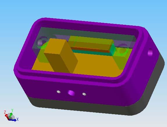
12 Modulator Design eom_assembly.easm 12
13 Dynamic RFAM Would like to see a measurement of the dynamic RFAM, with comparison to the current LiNbO3 modulators. Measured RFAM in RTP EOMs vs laser heating power Static RFAM measured over 20 min period ΔIΩmod / I DC ~ Ω mod = 19.7 MHz (No attempt to correct and re-establish baseline upon heating) 13
14 RFAM in νfocus LiNbO 3 EOMs data from LLO PSL enclosure, Oct ΔIΩ mod /I DC 7 x 10⁻⁶ (Better now?) Comparison: LIGO1 EOMs somewhat better Possibly due to the lack of wedges on the crystal on RTP or temperature conditions could investigate temperature-stabilized EOMs RFAM (V) RFAM of Resonant Sideband 1V = 1.7 x 10⁻⁵ RFAM amplitude Time (sec) I Q Amplitude 14
15 One or three EOMs? Need to discuss the different options of driving & impedance matching to the crystal:» - single electrode vs multi-electrodes on the crystal» matching circuit components: inside vs outside the crystal housing - some progress toward a multiple frequency driver circuit, but more simulations and testing are needed before we feel confident that it will work. Matching circuits: for higher frequencies, better to put the matching circuit in the crystal housing» Driving the cable at high frequencies is difficult possible to get crystals as long as 40 mm» could put three electrodes (one for each frequency) on a single crystal.» Some thought would need to be put into defining the gap spacing and estimating the effects of fringing fields between the gaps. 15
16 EOMs in vacuum if we are tempted to mount a EO modulator in the vacuum system, after the MC, to be able to tune the signal recycling cavity, how would the design need to change for an in-vacuum unit? Two issues» Vacuum compatibility Replace teflon clamp with boron nitride Design EOM can for vacuum compatibility Matching circuit outside the vacuum Alternatively, put the EOM in its own vacuum container in the main vacuum» Beam size Similar to AdvLIGO PSL intensity stabilization PD? MC beam waist is 2.1 mm in Advanced LIGO Requires large diameter aperture 8 mm 70 ppm clipping or alternatively modify the layout to accommodate a 1 mm focus for the EOM after the MC Not obvious how to do this 16
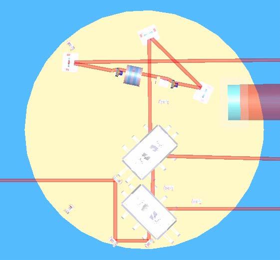
17 Faraday rotator (FR) Faraday isolator» Two 22.5 TGG-based rotators with a reciprocal 67.5 quartz rotator between» Polarization distortions from the first rotator compensated in the second.» ½ waveplate to set output polarization.» Thermal lens compensation via negative dn/dt material: deuterated potassium dihydrogen phosphate, KD 2 PO 4, or DKDP ). Most likely TFPs Mounted on breadboard as single component Polarizer Faraday TGG Crystals QR λ/2 DKDP Thermal Lens Compensation Polarizer H H 17
18 Isolation Requirement What is the basis of the isolation requirement? Somewhat ill-defined» iligo FI s provide ~ 30 db isolation» parasitic interferometers seen at power levels of a few watts into IFO in iligo» Scale to AdvLIGO powers (125W/4W): 15 db of additional isolation at least is needed to achieve the same performance Hard to get to 45 db, but not impossible 18
19 Thermal Drift/Steering Thermal beam drift/steering: the limit of 100 μrad seems too high, it's a large fraction of the beam divergence angle -- and we'd prefer not to have to use the RBS to compensate for it. Can we make it more like <10% of the beam divergence angle, which would be around 20 μrad? iligo upgrade (upper limit of 30 W through the FI) Drift ( μ rad) Calcite wedges Horizontal Vertical Time (s) Drift ( μ rad) TFPs Time (s) Horizontal Vertical Calcite: W; TFPs: 3 30W 19
20 Thermal Drift/Steering II Scaling to AdvLIGO (~ 150 W)» Calcite: 200 μrad» TFPs: 15 μrad Calcite potentially problematic for AdvLIGO» Could think about using double wedges for compensation, but beam separation may be a problem We recommend TFPs, and are working with ATF to develop special high extinction ratio coatings (10000:1) 20
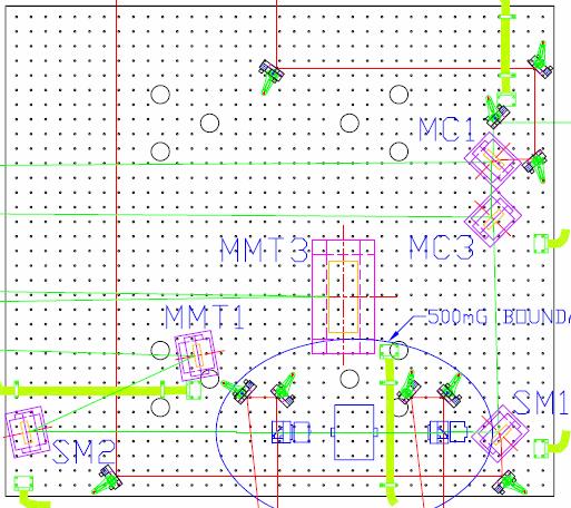
21 Beam Heights in iligo, AdvLIGO H1, L1 H2» FI moved downstream of MMT1» Need to account for rising beam from MMT1 MMT2 H1: 2.48 mrad; L1: 2.79 mrad Breadboard will be angled to align FI axis with beam axis Need to establish level REFL beam height HAM 1, since it will have same downward angle mm downward shift on first mirror Need to establish level diagnostic beam heights same idea» FI maintains position between SM1 and SM2 AdvLIGO» FI located between SM1 and MMTs where beam is level Beam height is 8.46 off table 21
22 H1, L1 layout (preliminary) 22
23 H2 layout (preliminary) 23

24 AdvLIGO layout (preliminary) 24
25 Spot Size in FI What is the assumed and/or optimum spot size in the Faraday? characterization measurements were performed with a beam size of ~ 1.9 mm» Beam in iligo is 1.6 mm 1.8 mm» Beam in AdvLIGO is 2.1 mm Thermal effects are first order insensitive to beam size In general, smaller is better to sample homogeneous magnetic field 25
26 FI Sensitivity to Beam Displacement How sensitive is the isolation to the transverse beam position? W 10 W Extinction Extintion, db (db) W 90 W 1.4 W 10 W 50 W 90 W Shift, mm Transverse Displacement, mm 26
27 Choice of Polarizers How about a hybrid approach, using the combination of a TFP + calcite polarizer. The REFL beam would come off the TFP, for low thermal drift, and the calcite would give high isolation. The TFP could even be just a piece of fused silica at Brewster's angle. Hybrid approach probably doesn t help much» Input polarizers sets isolation; REFL reflects off of it Working to develop high extinction ratio TFPs from ATF» All experiments on isolation ratio to date performed with calcite wedges Need to characterize sensitivity of extinction ratio to angle since beam will be steered in IO optics chain 27
28 Power budgets Where is the power going (for both the transmitted and rejected cases)? Are all the beams being sufficiently dumped? FI with TFPs:» Percent transmitted: 93.3% +/- 0.3%» Percent rejected: 90.3% +/- 0.3% FI with calcite wedge polarizers:» Percent transmitted: 98.3% +/- 0.3% Power Budget: TFP FI 3.4% ~ 99.95% 3.4% ~ 99.95%» Percent rejected: 94.6% +/- 1.0% Most or all of the beams from polarizers will be picked off and sent through viewports for diagnostic purposes ~ 90.3% 0.3% ~ 99.95% 3.4% 0.3% 28
29 Thermal Performance in Vacuum Thermal performance in vacuum: Has there been any analysis of this? Any problems foreseen? Maximum absorbed power is P ~ 1.5 W in TGG for AdvLIGO» Concern about long term heating of magnet» Assuming all heat is radiated, the temperature is: T = (P/εσA) 1/4 = 30 C Assume ε ~ 0.9, σ = Wien s constant, A=TGG surface area This is somewhat conservative TGG is thermal contact with rotator housing which is in good thermal contact with HAM tables 29
30 AR Coatings on Transmissive Optics Presumably all the elements have AR coatings... are they high quality? what are their specs? For the FI:» AR coatings were ~ 0.1% on all surfaces (14!) Calcite wedges» Could be reduced to 300 ppm FI through put limited by TGG and quartz rotator absorption: For calcite wedges: limit is ~ 99% For TFPs, limited by intrinsic polarizer losses 30

31 FI Vacuum Compatibility Would like to address vacuum compatibility. This seems to be not very mature at this time, and will need to be thoroughly reviewed before finalizing the design. Can we see a list of all components being used? Prototype FR underwent bake out in March 2006» All parts but optics baked at 60 C for 48 hours Magnet: sintered NiFeB Housing: aluminum with one titanium part» Failed miserably 31

32 FI Vacuum Compatibility II But this was not an unexpected result» Prototype designed and assembled by IAP not for vacuum testing but for optical testing Blind holes in design Not assembled in LIGO clean environment Housing undergoing redesign by UF to address vacuum issues Vacuum compatible version will be first baked and then assembled in clean conditions» in optics labs at one of the sites (during an S5 break)» Ready by late summer russian_fr.easm 32
33 Views to the FI Need to think about being able to view important points of the assembly from outside the vacuum system; mirrors may need to be included to provide views. For iligo upgrade, it will be possible to place mirrors on the HAM that will provide views from cameras mounted in the upper HAM door viewports» Access to the entrance aperture of the FR on HAM1 may be difficult, because component positions are constrained by beams Should be able to get a look at the polarizer For AdvLIGO, layout is still sufficiently preliminary» HAM 1 is relatively clear where FI is located, so FI components can be separated 33

34 Views to the FI: HAM1 34
35 Low Frequency B-Field Coupling You've analyzed the effects in the GW band (100 Hz). What about the static B-field, or the fluctuations at the stack modes for iligo -- could these be large enough to torque around any of the suspended optics? B-fields exerts torques and forces on the mirrors» F = (μ B), torque: τ = μ x B» Static forces and torques can be compensated by initial alignment» Rotation: Φ < 3x10⁻⁸ rad x B/[G/m] Φ < 4x10⁻⁷ rad x B/[G] 35
36 Low Frequency B-Field Coupling 36
37 Supplementary Material 37
38 RTP Thermal properties Properties Units RTP RTA KTP LiNb0 3 dn x /dt 10-6 /K dn y /dt 10-6 /K dn z /dt 10-6 /K κ x W/Km κ y W/Km κ z W/Km α cm -1 < < < < 0.05 Q x 1/W Q y 1/W Q z 1/W
39 Optical and electrical properties Properties Units/conditions RTP RTA LiNbO 3 Damage Threshold MW/cm 2, > n x 1064nm n y 1064nm n z 1064nm Absorption coeff. α cm -1 (1064 nm) < < < r 33 pm/v r 23 pm/v r 13 pm/v r 42 pm/v?? 28 r 51 pm/v?? 28 r 22 pm/v 3.4 n z3 r 33 pm/v Dielectric const., ε z 500 khz, 22 o C Conductivity, σ z Ω 1 cm -1, 10 MHz ~10-9 3x10⁻⁷ Loss Tangent, d z 500 khz, 22 o C
40 Modulator parameters The largest EO-coefficient is r 33. Modulation depth (L = crystal length, U z = voltage, d = thickness) πl 3 U z ΔΦ = m = r33nz λ d For a modulation depth of m = 0.5: L U z = 708V d For L = 2.0 cm and d = 0.4 cm, U z = 124 V. Resonant circuit reduces voltage by Q~5-20. RF power loss in the microwatt range 40
41 Performance 19.7 MHz matching circuit had Q = 20; 180 MHz, Q = MHz modulator gave m = 0.2 with 5 V rms RF in» 12 V rms -> m = 0.5.» 4 W RF into 50 Ω. 180 MHz modulator gave m = 0.2 with 30 V rms RF in» 75 V -> m = 0.5.» 120 W into 50 Ω 41
42 Ongoing noise measurements Characterize excess phase and amplitude noise Modulated, intensity-stabilized NPRO beats against 2 nd -locked, intensity-stabilized NPRO» intensity stabilization ~10-8 /rhz at 100 Hz» Components to go into vacuum 42
43 Damage In advanced LIGO, the central intensity in the EOM is: P( r = 0) kw cm approximately 6000 times below the damage threshold quoted for 10 ns pulses We subjected an RTP crystal to 90 W of 1064 nm light for 300 hours, with no damage or other changes in properties. 43
44 FI performance specifications Parameter Goal Comment Optical throughput (%) > 95% Limited by absorption in TGG and DKDP, surface reflections in the FI components (total of 16 surfaces) Isolation ratio (db) > 30 db Limited entirely by extinction ratio of thin film polarizers[1] Thermal lens power (m -1 ) < 0.02 Leads to <2% reduction in mode-matching Thermal beam drift (μrad) < 100 Based on dynamic range of RBS actuators [1] It may be possible to use calcite wedge polarizers (which have extinction ratios in excess of 10 5 ), which would improve the isolation specification to > 40 db. 44
45 Faraday performance Optical isolation measured with beam reflected from the HR mirror High quality calcite wedge polarizers used (extinction ratio > 10 5 ) Not limited by the extinction ratio of the polarizers. P In, forward Pol λ/2 TGG QR TGG Pol DKDP P T, forward HR Mirror P T, b ackward P R, backward H H P In, back ward 45

46 Mechanical design TGG and quartz crystals all in large magnet housing TFP s on stands, orientation controlled by mechanical design DKDP compensator on fixed stand ½ wave plate on CVI vacuum-compatible rotator 46
47 Isolation Isolation as function of incident laser power 50» Red circles: Advanced LIGO design» Black squares: LIGO 1 FI At 30 W, ~ 46 db isolation If TFPs are used, isolation ~ 30 db Optical Isolation Current EOT Isolator Compensated Isolator Incident Laser Power 47
48 Incident angle variations Isolation ratio vs angle of incidence» Black points correspond to angular deviations parallel or perpendicular to the laser polarization axis and represent the minimum depolarization. Isolation ratio (db)» Red points correspond to angular 28 deviations at 45 o perp. or par. to laser polarization to the deg to laser polarization polarization axis (worst case) Incident Angle (mrad)
49 Thermal lensing DKPD was placed before the FI as lens compensator Only single-pass lensing measured» Location of the DKPD in the upgrade will either be between the polarizer and wave plate or between the FI and the PRM DKD Pol TGG QR TGG λ/2 Pol WinCAM Δz 49
50 Thermal lens results Thermal lens (in m -1 ) in the FI as a function of incident laser power.» Black squares show focal power of the FI (no thermal compensation)» Red circles show DKDP focal power» Green triangles show focal power for the fully compensated FI. At 70 W, f = 40 m Focal Power (m -1 ) Rotator only Compensator only Rotator and Compensator Incident Power (W) 50
51 HAM layouts for MLU Drawings of advanced LIGO FI in HAMS 1 and 7 in next two slides Main beam is green; aux beams are red Beam dumps» There are ghost beams from most surfaces» Will have to be identified and dumped 0.5 Gauss boundary is shown See docs for magnetic field couplings. They are manageable. Vacuum compatible design is underway 51


52 New Faraday in HAM 1 52
53 New Faraday in HAM 7 53
High-Frequency Electro-Optic Phase Modulators
 USER S GUIDE High-Frequency Electro-Optic Phase Modulators Models 442X, 443X, 444X, 446X, 48XX U.S. Patent #5,414,552 3635 Peterson Way Santa Clara, CA 95054 USA phone: (408) 980-5903 fax: (408) 987-3178
Electro-optic components and system
 Electro-optic components and system Optical Isolators 700 Series Faraday Rotator and Accessories The unique feature of a Faraday rotator is its nonreciprocity, that is, the fact that the "handedness" of
Model Series 400X User s Manual. DC-100 MHz Electro-Optic Phase Modulators
 Model Series 400X User s Manual DC-100 MHz Electro-Optic Phase Modulators 400412 Rev. D 2 Is a registered trademark of New Focus, Inc. Warranty New Focus, Inc. guarantees its products to be free of defects
Installation and Characterization of the Advanced LIGO 200 Watt PSL
 Installation and Characterization of the Advanced LIGO 200 Watt PSL Nicholas Langellier Mentor: Benno Willke Background and Motivation Albert Einstein's published his General Theory of Relativity in 1916,
User s Guide Modulator Alignment Procedure
 User s Guide Modulator Alignment Procedure Models 350, 360, 370, 380, 390 series Warranty Information ConOptics, Inc. guarantees its products to be free of defects in materials and workmanship for one
Optical Isolator Tutorial (Page 1 of 2) νlh, where ν, L, and H are as defined below. ν: the Verdet Constant, a property of the
 νlh, where ν, L, and H are as defined below. ν: the Verdet Constant, a property of the") Aspheric Optical Isolator Tutorial (Page 1 of 2) Function An optical isolator is a passive magneto-optic device that only allows light to travel in one direction. Isolators are used to protect a source
Aspheric Optical Isolator Tutorial (Page 1 of 2) Function An optical isolator is a passive magneto-optic device that only allows light to travel in one direction. Isolators are used to protect a source
User s Guide Modulator Alignment Procedure
 User s Guide Modulator Alignment Procedure Models 350, 360, 370, 380, 390 series Warranty Information Conoptics, Inc. guarantees its products to be free of defects in materials and workmanship for one
Faraday Rotators and Isolators
 Faraday Rotators and I. Introduction The negative effects of optical feedback on laser oscillators and laser diodes have long been known. Problems include frequency instability, relaxation oscillations,
The VIRGO detection system
 LIGO-G050017-00-R Paolo La Penna European Gravitational Observatory INPUT R =35 R=0.9 curv =35 0m 95 MOD CLEAN ER (14m )) WI N d:yag plar=0 ne.8 =1λ 064nm 3km 20W 6m 66.4m M odulat or PR BS N I sing lefrequ
High-Power, Passively Q-switched Microlaser - Power Amplifier System
 High-Power, Passively Q-switched Microlaser - Power Amplifier System Yelena Isyanova Q-Peak, Inc.,135 South Road, Bedford, MA 01730 isyanova@qpeak.com Jeff G. Manni JGM Associates, 6 New England Executive
DC-250 MHz Electro-Optic Phase Modulators Models 4001, 4002, 4003, 4004, 4061, 4062, 4063, 4064
 USER S GUIDE DC-250 MHz Electro-Optic Phase Modulators Models 4001, 4002, 4003, 4004, 4061, 4062, 4063, 4064 U.S. Patent # 5,189,547 2584 Junction Ave. San Jose, CA 95134-1902 USA phone: (408) 919 1500
High-Frequency Electro-Optic Phase Modulators
 USER S GUIDE High-Frequency Electro-Optic Phase Modulators Models 442x, 443x, & 485x U.S. Patent # 5,414,552 3635 Peterson Way Santa Clara, CA 95054 USA phone: (408) 980-5903 fax: (408) 987-3178 e-mail:
Arm Cavity Finesse for Advanced LIGO
 LASER INTERFEROMETER GRAVITATIONAL WAVE OBSERVATORY - LIGO - CALIFORNIA INSTITUTE OF TECHNOLOGY MASSACHUSETTS INSTITUTE OF TECHNOLOGY Technical Note LIGO-T070303-01-D Date: 2007/12/20 Arm Cavity Finesse
CHAPTER 5 FINE-TUNING OF AN ECDL WITH AN INTRACAVITY LIQUID CRYSTAL ELEMENT
 CHAPTER 5 FINE-TUNING OF AN ECDL WITH AN INTRACAVITY LIQUID CRYSTAL ELEMENT In this chapter, the experimental results for fine-tuning of the laser wavelength with an intracavity liquid crystal element
User s Guide Modulator Alignment Procedure
 User s Guide Modulator Alignment Procedure Models 350, 360, 370, 380, 390 series Warranty Information ConOptics, Inc. guarantees its products to be free of defects in materials and workmanship for one
Initial Results from the C-Mod Prototype Polarimeter/Interferometer
 Initial Results from the C-Mod Prototype Polarimeter/Interferometer K. R. Smith, J. Irby, R. Leccacorvi, E. Marmar, R. Murray, R. Vieira October 24-28, 2005 APS-DPP Conference 1 Abstract An FIR interferometer-polarimeter
Compensating thermal lensing in Faraday rotators.
 Compensating thermal lensing in Faraday rotators. Donovan McFeron University of Florida. New Physics Building Corner of Museum and North South Drive Gainesville, FL 36 ( August 3, 000) ABSTRACT An analyzer
880 Quantum Electronics Optional Lab Construct A Pulsed Dye Laser
 880 Quantum Electronics Optional Lab Construct A Pulsed Dye Laser The goal of this lab is to give you experience aligning a laser and getting it to lase more-or-less from scratch. There is no write-up
Stable Recycling Cavities for Advanced LIGO
 Stable Recycling Cavities for Advanced LIGO Guido Mueller University of Florida 08/16/2005 Table of Contents Stable vs. unstable recycling cavities Design of stable recycling cavity Design drivers Spot
Fibre Optic Sensors: basic principles and most common applications
 SMR 1829-21 Winter College on Fibre Optics, Fibre Lasers and Sensors 12-23 February 2007 Fibre Optic Sensors: basic principles and most common applications (PART 2) Hypolito José Kalinowski Federal University
Development of scalable laser technology for EUVL applications
 Development of scalable laser technology for EUVL applications Tomáš Mocek, Ph.D. Chief Scientist & Project Leader HiLASE Centre CZ.1.05/2.1.00/01.0027 Lasers for real-world applications Laser induced
Development of C-Mod FIR Polarimeter*
 Development of C-Mod FIR Polarimeter* P.XU, J.H.IRBY, J.BOSCO, A.KANOJIA, R.LECCACORVI, E.MARMAR, P.MICHAEL, R.MURRAY, R.VIEIRA, S.WOLFE (MIT) D.L.BROWER, W.X.DING (UCLA) D.K.MANSFIELD (PPPL) *Supported
1. INTRODUCTION 2. LASER ABSTRACT
 Compact solid-state laser to generate 5 mj at 532 nm Bhabana Pati*, James Burgess, Michael Rayno and Kenneth Stebbins Q-Peak, Inc., 135 South Road, Bedford, Massachusetts 01730 ABSTRACT A compact and simple
SELECTION GUIDE MULTIPLE-ORDER QUARTZ WAVEPLATES ZERO-ORDER QUARTZ WAVEPLATES DUAL-WAVELENGTH WAVEPLATES... 85
 WAVEPLATES Mirrors Waveplates are used in applications where the control, synthesis, or analysis of the polarization state of an incident beam of light is required. Our waveplates are constructed of very
Experimental Physics. Experiment C & D: Pulsed Laser & Dye Laser. Course: FY12. Project: The Pulsed Laser. Done by: Wael Al-Assadi & Irvin Mangwiza
 Experiment C & D: Course: FY1 The Pulsed Laser Done by: Wael Al-Assadi Mangwiza 8/1/ Wael Al Assadi Mangwiza Experiment C & D : Introduction: Course: FY1 Rev. 35. Page: of 16 1// In this experiment we
Laser Speckle Reducer LSR-3000 Series
 Datasheet: LSR-3000 Series Update: 06.08.2012 Copyright 2012 Optotune Laser Speckle Reducer LSR-3000 Series Speckle noise from a laser-based system is reduced by dynamically diffusing the laser beam. A
Department of Electrical Engineering and Computer Science
 MASSACHUSETTS INSTITUTE of TECHNOLOGY Department of Electrical Engineering and Computer Science 6.161/6637 Practice Quiz 2 Issued X:XXpm 4/XX/2004 Spring Term, 2004 Due X:XX+1:30pm 4/XX/2004 Please utilize
The Lightwave Model 142 CW Visible Ring Laser, Beam Splitter, Model ATM- 80A1 Acousto-Optic Modulator, and Fiber Optic Cable Coupler Optics Project
 The Lightwave Model 142 CW Visible Ring Laser, Beam Splitter, Model ATM- 80A1 Acousto-Optic Modulator, and Fiber Optic Cable Coupler Optics Project Stephen W. Jordan Seth Merritt Optics Project PH 464
Lithium Triborate (LiB 3 O 5, LBO) Introductions
 Introductions") s Laser s NLO s Birefringent s AO and EO s Lithium Triborate (LiB 3 O 5, ) Introductions Banner Union provide the high quality Broad transparency range from 160nm to 2600nm; High optical homogeneity (δn
s Laser s NLO s Birefringent s AO and EO s Lithium Triborate (LiB 3 O 5, ) Introductions Banner Union provide the high quality Broad transparency range from 160nm to 2600nm; High optical homogeneity (δn
Intracavity, common resonator, Nd:YAG pumped KTP OPO
 Intracavity, common resonator, Nd:YAG pumped KTP OPO James Beedell* a, Ian Elder a, David Legge a & Duncan Hand b a SELEX Galileo, Crewe Toll House, 2 Crewe Road North, Edinburgh EH5 2XS, UK b School of
EE119 Introduction to Optical Engineering Spring 2003 Final Exam. Name:
 EE119 Introduction to Optical Engineering Spring 2003 Final Exam Name: SID: CLOSED BOOK. THREE 8 1/2 X 11 SHEETS OF NOTES, AND SCIENTIFIC POCKET CALCULATOR PERMITTED. TIME ALLOTTED: 180 MINUTES Fundamental
Electro-Optic Sensors for RF Electric Fields: a Diagnostic Tool for Microwave Circuits and Antennas
 Electro-Optic Sensors for RF Electric Fields: a Diagnostic Tool for Microwave Circuits and Antennas If any of the enclosed materials are to be cited in other publications, the users are responsible for
A Thermal Compensation System for the gravitational wave detector Virgo
 A Thermal Compensation System for the gravitational wave detector Virgo M. Di Paolo Emilio University of L Aquila and INFN Roma Tor Vergata On behalf of the Virgo Collaboration Index: 1) Thermal Lensing
Computer Generated Holograms for Optical Testing
 Computer Generated Holograms for Optical Testing Dr. Jim Burge Associate Professor Optical Sciences and Astronomy University of Arizona jburge@optics.arizona.edu 520-621-8182 Computer Generated Holograms
A gravitational wave is a differential strain in spacetime. Equivalently, it is a differential tidal force that can be sensed by multiple test masses.
 A gravitational wave is a differential strain in spacetime. Equivalently, it is a differential tidal force that can be sensed by multiple test masses. Plus-polarization Cross-polarization 2 Any system
Multiply Resonant EOM for the LIGO 40-meter Interferometer
 LASER INTERFEROMETER GRAVITATIONAL WAVE OBSERVATORY - LIGO - CALIFORNIA INSTITUTE OF TECHNOLOGY MASSACHUSETTS INSTITUTE OF TECHNOLOGY LIGO-XXXXXXX-XX-X Date: 2009/09/25 Multiply Resonant EOM for the LIGO
WL Photonics Inc. Leading Provider of Fiber Optic Wavelength Tuning and Conditioning Solutions
 Faraday Optical Isolator FI-PS-, FI-PI- & FI-BP- Faraday optical isolators of FI- series are built with the superior materials of large Verdet constant, high thermal conductivity, low absorption coefficient
Electro-optic components and systems Toll Free:
 Electro-optic components and systems Toll Free: 800 748 3349 Laser Modulation Choose from our line of modulators and driver electronics Conoptics manufactures an extensive line of low voltage electro-optic
Increasing the laser power incident on the recycling mirrors in the LIGO interferometers
 LASER INTERFEROMETER GRAVITATIONAL WAVE OBSERVATORY -LIGO- CALIFORNIA INSTITUTE OF TECHNOLOGY MASSACHUSETTS INSTITUTE OF TECHNOLOGY Technical Note LIGO-T030288-00-W 12/09/03 Increasing the laser power
OPERATING MANUAL. ACOUSTO OPTIC MODULATOR MODEL NUMBER: X-LTD X= 1, 2, or 3 mm DOCUMENT NUMBER: 51A00620D
 OPERATING MANUAL ACOUSTO OPTIC MODULATOR MODEL NUMBER: 23080-1 23080-X-LTD X= 1, 2, or 3 mm DOCUMENT NUMBER: 51A00620D Document approved for release: W Seale Date: 6/20/06 US OFFICE:. 4005 Opportunity
LISA and SMART2 Optical Work in Europe
 LISA and SMART2 Optical Work in Europe David Robertson University of Glasgow Outline Overview of current optical system work Title Funded by Main focus Prime Phase Measuring System LISA SMART2 SEA (Bristol)
Radial Polarization Converter With LC Driver USER MANUAL
 ARCoptix Radial Polarization Converter With LC Driver USER MANUAL Arcoptix S.A Ch. Trois-portes 18 2000 Neuchâtel Switzerland Mail: info@arcoptix.com Tel: ++41 32 731 04 66 Principle of the radial polarization
Adaptive Optics for LIGO
 Adaptive Optics for LIGO Justin Mansell Ginzton Laboratory LIGO-G990022-39-M Motivation Wavefront Sensor Outline Characterization Enhancements Modeling Projections Adaptive Optics Results Effects of Thermal
DESIGN OF COMPACT PULSED 4 MIRROR LASER WIRE SYSTEM FOR QUICK MEASUREMENT OF ELECTRON BEAM PROFILE
 1 DESIGN OF COMPACT PULSED 4 MIRROR LASER WIRE SYSTEM FOR QUICK MEASUREMENT OF ELECTRON BEAM PROFILE PRESENTED BY- ARPIT RAWANKAR THE GRADUATE UNIVERSITY FOR ADVANCED STUDIES, HAYAMA 2 INDEX 1. Concept
Pockels Cells. Selection Guide. BBO Pockels Cells page 3.4. DQ High Repetition Rate Pockels Cell Driver for Q-Switching page 3.6
 Selection Guide Drivers & High Voltage Supplies KTP page 3.2 Mounting Stage for of Ø25.4 mm page 3.5 DPB High Voltage Pockels Cell Driver page 3.12 KD*P page 3.3 Pulse Picking Solutions page 3.15 Mounting
Chapter Ray and Wave Optics
 109 Chapter Ray and Wave Optics 1. An astronomical telescope has a large aperture to [2002] reduce spherical aberration have high resolution increase span of observation have low dispersion. 2. If two
How to Build a Gravitational Wave Detector. Sean Leavey
 How to Build a Gravitational Wave Detector Sean Leavey Supervisors: Dr Stefan Hild and Prof Ken Strain Institute for Gravitational Research, University of Glasgow 6th May 2015 Gravitational Wave Interferometry
Pockels Cells. Selection Guide. KD*P Pockels Cells page 3.3. DQ High Repetition Rate Pockels Cell Driver for Q-Switching page 3.6
 Selection Guide Drivers & High Voltage Supplies KTP page 3.2 Mounting Stages for of Ø25.4 mm page 3.5 DPB High Voltage Pockels Cell Driver page 3.12 Pulse Picking Solutions page 3.15 Mounting Stages for
The AEI 10 m Prototype. June Sina Köhlenbeck for the 10m Prototype Team
 The AEI 10 m Prototype June 2014 - Sina Köhlenbeck for the 10m Prototype Team The 10m Prototype Seismic attenuation system Suspension Platform Inteferometer SQL Interferometer Suspensions 2 The AEI 10
Sintec Optronics Pte Ltd
 Sintec Optronics Pte Ltd Study of a Second Harmonic Nd:YAG Laser ABSTRACT A second harmonic generator was designed and set-up. The factors affecting conversion efficiency and beam quality were discussed.
Results from the Stanford 10 m Sagnac interferometer
 INSTITUTE OF PHYSICSPUBLISHING Class. Quantum Grav. 19 (2002) 1585 1589 CLASSICAL ANDQUANTUM GRAVITY PII: S0264-9381(02)30157-6 Results from the Stanford 10 m Sagnac interferometer Peter T Beyersdorf,
LASER INTERFEROMETER GRAVITATIONAL WAVE OBSERVATORY - LIGO - CALIFORNIA INSTITUTE OF TECHNOLOGY MASSACHUSETTS INSTITUTE OF TECHNOLOGY
 LASER INTERFEROMETER GRAVITATIONAL WAVE OBSERVATORY - LIGO - CALIFORNIA INSTITUTE OF TECHNOLOGY MASSACHUSETTS INSTITUTE OF TECHNOLOGY Technical Report LIGO-T010061-00- D 5/16/01 ISC Electrooptic Shutter:
Commissioning of Advanced Virgo
 Commissioning of Advanced Virgo VSR1 VSR4 VSR5/6/7? Bas Swinkels, European Gravitational Observatory on behalf of the Virgo Collaboration GWADW Takayama, 26/05/2014 B. Swinkels Adv. Virgo Commissioning
Application Instruction 002. Superluminescent Light Emitting Diodes: Device Fundamentals and Reliability
 I. Introduction II. III. IV. SLED Fundamentals SLED Temperature Performance SLED and Optical Feedback V. Operation Stability, Reliability and Life VI. Summary InPhenix, Inc., 25 N. Mines Road, Livermore,
EE119 Introduction to Optical Engineering Fall 2009 Final Exam. Name:
 EE119 Introduction to Optical Engineering Fall 2009 Final Exam Name: SID: CLOSED BOOK. THREE 8 1/2 X 11 SHEETS OF NOTES, AND SCIENTIFIC POCKET CALCULATOR PERMITTED. TIME ALLOTTED: 180 MINUTES Fundamental
PHYS 241 FINAL EXAM December 11, 2006
 1. (5 points) Light of wavelength λ is normally incident on a diffraction grating, G. On the screen S, the central line is at P and the first order line is at Q, as shown. The distance between adjacent
Preliminary Optical Fiber Stabilization for AdvLIGO Pre-Lock Acquisition System
 T080352-00 Preliminary Optical Fiber Stabilization for AdvLIGO Pre-Lock Acquisition System Jaclyn R. Sanders Mentors: Dick Gustafson, Paul Schwinberg, Daniel Sigg Abstract Advanced LIGO requires a seismic
Stable recycling cavities for Advanced LIGO
 Stable recycling cavities for Advanced LIGO Guido Mueller LIGO-G070691-00-D with input/material from Hiro Yamamoto, Bill Kells, David Ottaway, Muzammil Arain, Yi Pan, Peter Fritschel, and many others Stable
Development of a Deformable Mirror for High-Power Lasers
 Development of a Deformable Mirror for High-Power Lasers Dr. Justin Mansell and Robert Praus MZA Associates Corporation Mirror Technology Days August 1, 2007 1 Outline Introduction & Project Goal Deformable
GOOCH & HOUSEGO NOVEL OPTICAL COMPONENTS FOR THE IR
 GOOCH & HOUSEGO NOVEL OPTICAL COMPONENTS FOR THE IR June 017 Gooch & Housego NOVEL Optical components for the IR Acousto-Optic components for:- µm < λ < 4µm Novel Optical Components Slide ACOUSTO OPTICS
The VIRGO suspensions
 INSTITUTE OF PHYSICSPUBLISHING Class. Quantum Grav. 19 (2002) 1623 1629 CLASSICAL ANDQUANTUM GRAVITY PII: S0264-9381(02)30082-0 The VIRGO suspensions The VIRGO Collaboration (presented by S Braccini) INFN,
SECOND HARMONIC GENERATION AND Q-SWITCHING
 SECOND HARMONIC GENERATION AND Q-SWITCHING INTRODUCTION In this experiment, the following learning subjects will be worked out: 1) Characteristics of a semiconductor diode laser. 2) Optical pumping on
9) Describe the down select process that led to the laser selection in more detail
 Describe the down select process that led to the laser selection in more detail") 9) Describe the down select process that led to the laser selection in more detail David Shoemaker NSF Annual Review of the LIGO Laboratory 18 November 2003 Process Interested research groups pursued separate
9) Describe the down select process that led to the laser selection in more detail David Shoemaker NSF Annual Review of the LIGO Laboratory 18 November 2003 Process Interested research groups pursued separate
Lasers for Advanced Interferometers
 Lasers or Advanced Intererometers Benno Willke Aspen Meeting Aspen CO, February 2004 G040041-00-Z Requirements - Topology Sagnac: broadband source to reduce scattered light noise power control recycled
Characterization of an Electro-Optical Modulator for Next Linear Collider. Photocathode Research
 SLAC-TN-04-062 September 2004 Characterization of an Electro-Optical Modulator for Next Linear Collider Photocathode Research Matthew Kirchner Office of Science, Student Undergraduate Laboratory Internship
Ultra-stable flashlamp-pumped laser *
 SLAC-PUB-10290 September 2002 Ultra-stable flashlamp-pumped laser * A. Brachmann, J. Clendenin, T.Galetto, T. Maruyama, J.Sodja, J. Turner, M. Woods Stanford Linear Accelerator Center, 2575 Sand Hill Rd.,
Autotracker III. Applications...
 Autotracker III Harmonic Generation System Model AT-III Applications... Automatic Second Harmonic and Third Harmonic Generation of UV Wavelengths Automatic Production of IR Wavelengths by Difference Frequency
Physics 431 Final Exam Examples (3:00-5:00 pm 12/16/2009) TIME ALLOTTED: 120 MINUTES Name: Signature:
 TIME ALLOTTED: 120 MINUTES Name: Signature:") Physics 431 Final Exam Examples (3:00-5:00 pm 12/16/2009) TIME ALLOTTED: 120 MINUTES Name: PID: Signature: CLOSED BOOK. TWO 8 1/2 X 11 SHEET OF NOTES (double sided is allowed), AND SCIENTIFIC POCKET CALCULATOR
Physics 431 Final Exam Examples (3:00-5:00 pm 12/16/2009) TIME ALLOTTED: 120 MINUTES Name: PID: Signature: CLOSED BOOK. TWO 8 1/2 X 11 SHEET OF NOTES (double sided is allowed), AND SCIENTIFIC POCKET CALCULATOR
Lithium Triborate (LiB 3 O 5, LBO)
") NLO Cr ys tals Introduction Lithium Triborate (LiB 3 O 5, LBO) Lithium Triborate (LiB 3 O 5 or LBO) is an excellent nonlinear optical crystal discovered and developed by FIRSM, CAS (Fujian Institute of
NLO Cr ys tals Introduction Lithium Triborate (LiB 3 O 5, LBO) Lithium Triborate (LiB 3 O 5 or LBO) is an excellent nonlinear optical crystal discovered and developed by FIRSM, CAS (Fujian Institute of
Lab 5 - Electro-Optic Modulation
 Lab 5 - Electro-Optic Modulation Goal To measure the characteristics of waveplates and electro-optic modulators Prelab Background Saleh and Tiech Section 1st edition 18.1-18.3 or 20.1-20.3 in second edition.
queensgate a brand of Elektron Technology
 NanoSensors NX/NZ NanoSensor The NanoSensor is a non-contact position measuring system based on the principle of capacitance micrometry. Two sensor plates, a Target and a Probe, form a parallel plate capacitor.
TCS beam shaping: optimum and achievable beam profiles for correcting thermo-refractive lensing (not thermo-elastic surface deformation)
") LASER INTERFEROMETER GRAVITATIONAL WAVE OBSERVATORY Laboratory / Scientific Collaboration -T1200103-v2 Date: 28-Feb-12 TCS beam shaping: optimum and achievable beam profiles for correcting thermo-refractive
LASER INTERFEROMETER GRAVITATIONAL WAVE OBSERVATORY Laboratory / Scientific Collaboration -T1200103-v2 Date: 28-Feb-12 TCS beam shaping: optimum and achievable beam profiles for correcting thermo-refractive
Will contain image distance after raytrace Will contain image height after raytrace
 Name: LASR 51 Final Exam May 29, 2002 Answer all questions. Module numbers are for guidance, some material is from class handouts. Exam ends at 8:20 pm. Ynu Raytracing The first questions refer to the
MRO Delay Line. Performance of Beam Compressor for Agilent Laser Head INT-406-VEN The Cambridge Delay Line Team. rev 0.
 MRO Delay Line Performance of Beam Compressor for Agilent Laser Head INT-406-VEN-0123 The Cambridge Delay Line Team rev 0.45 1 April 2011 Cavendish Laboratory Madingley Road Cambridge CB3 0HE UK Change
plasmonic nanoblock pair
 Nanostructured potential of optical trapping using a plasmonic nanoblock pair Yoshito Tanaka, Shogo Kaneda and Keiji Sasaki* Research Institute for Electronic Science, Hokkaido University, Sapporo 1-2,
OPERATING MANUAL. ACOUSTO OPTIC MODULATOR MODEL NUMBER: X-1.06-LTD X= 1, 2, or 3 mm DOCUMENT NUMBER: 51A14950A
 OPERATING MANUAL ACOUSTO OPTIC MODULATOR MODEL NUMBER: X= 1, 2, or 3 mm DOCUMENT NUMBER: 51A14950A Document approved for release: W Seale Date: 6/06/06 US OFFICE: NEOS Technologies, Inc. 4005 Opportunity
Holography Transmitter Design Bill Shillue 2000-Oct-03
 Holography Transmitter Design Bill Shillue 2000-Oct-03 Planned Photonic Reference Distribution for Test Interferometer The transmitter for the holography receiver is made up mostly of parts that are already
Wavelength Control and Locking with Sub-MHz Precision
 Wavelength Control and Locking with Sub-MHz Precision A PZT actuator on one of the resonator mirrors enables the Verdi output wavelength to be rapidly tuned over a range of several GHz or tightly locked
The Core Optics. Input Mirror T ~ 3% T ~ 3% Signal Recycling Photodetector
 The Core Optics End Mirror Power Recycling Mirror Input Mirror T ~ 3% T ~ 3% End Mirror T ~ 10 ppm Laser Nd:Yag 6 W 100 W 12 kw 20 m 4000 m Signal Recycling Photodetector Mirror (dark fringe) Fold mirrors
ModBox Pulse Generation Unit
 ModBox Pulse Generation Unit The ModBox Family The ModBox systems are a family of turnkey optical transmitters and external modulation benchtop units for digital and analog transmission, pulsed and other
Electro-Optic Modulators
 Electro-Optic Modulators Electro-Optic Modulator Family Scientists and engineers rely on our optical modulators for exceptional performance, quality, ease of use, broad selection, and excellent value.
Nmark AGV-HP. High Accuracy, Thermally Stable Galvo Scanner
 Nmark AGV-HP Galvanometer Nmark AGV-HP High Accuracy, Thermally Stable Galvo Scanner Highest accuracy scanner available attains single-digit, micron-level accuracy over the field of view Optical feedback
Testbed for prototypes of the LISA point-ahead angle mechanism
 Testbed for prototypes of the LISA point-ahead angle mechanism, Benjamin Sheard, Gerhard Heinzel and Karsten Danzmann Albert-Einstein-Institut Hannover 7 th LISA Symposium Barcelona, 06/16/2008 Point-ahead
Nmark AGV-HP. High Accuracy, Thermally Stable Galvo Scanner
 Nmark AGV-HP High Accuracy, Thermally Stable Galvo Scanner Highest accuracy scanner available attains single-digit, micron-level accuracy over the field of view Optical feedback technology significantly
Collimation Tester Instructions
 Description Use shear-plate collimation testers to examine and adjust the collimation of laser light, or to measure the wavefront curvature and divergence/convergence magnitude of large-radius optical
TEPZZ 7 8 9ZA_T EP A1 (19) (11) EP A1. (12) EUROPEAN PATENT APPLICATION published in accordance with Art.
 (11) EP A1. (12) EUROPEAN PATENT APPLICATION published in accordance with Art.") (19) TEPZZ 7 8 9ZA_T (11) EP 2 728 390 A1 (12) EUROPEAN PATENT APPLICATION published in accordance with Art. 153(4) EPC (43) Date of publication: 07.05.2014 Bulletin 2014/19 (21) Application number: 12804964.0
(19) TEPZZ 7 8 9ZA_T (11) EP 2 728 390 A1 (12) EUROPEAN PATENT APPLICATION published in accordance with Art. 153(4) EPC (43) Date of publication: 07.05.2014 Bulletin 2014/19 (21) Application number: 12804964.0
5 Advanced Virgo: interferometer configuration
 5 Advanced Virgo: interferometer configuration 5.1 Introduction This section describes the optical parameters and configuration of the AdV interferometer. The optical layout and the main parameters of
Optical design of shining light through wall experiments
 Optical design of shining light through wall experiments Benno Willke Leibniz Universität Hannover (member of the ALPS collaboration) Vistas in Axion Physics: A Roadmap for Theoretical and Experimental
Optical Communications and Networking 朱祖勍. Sept. 25, 2017
 Optical Communications and Networking Sept. 25, 2017 Lecture 4: Signal Propagation in Fiber 1 Nonlinear Effects The assumption of linearity may not always be valid. Nonlinear effects are all related to
First step in the industry-based development of an ultra-stable optical cavity for space applications
 First step in the industry-based development of an ultra-stable optical cavity for space applications B. Argence, E. Prevost, T. Levêque, R. Le Goff, S. Bize, P. Lemonde and G. Santarelli LNE-SYRTE,Observatoire
Narrow line diode laser stacks for DPAL pumping
 Narrow line diode laser stacks for DPAL pumping Tobias Koenning David Irwin, Dean Stapleton, Rajiv Pandey, Tina Guiney, Steve Patterson DILAS Diode Laser Inc. Joerg Neukum Outline Company overview Standard
Lecture 04: Solar Imaging Instruments
 Hale COLLAGE (NJIT Phys-780) Topics in Solar Observation Techniques Lecture 04: Solar Imaging Instruments Wenda Cao New Jersey Institute of Technology Valentin M. Pillet National Solar Observatory SDO
OFR. Air-Path Isolators. For Fiber-Optic Isolators. see FIBER-OPTIC PRODUCTS Section
 OFR F A R A D A Y E F F E C T P R O D U C T S Air-Path Isolators For Fiber-Optic Isolators see FIBER-OPTIC PRODUCTS Section Table of Contents CONTENTS OFR and Isolators Page IO-1 aser Power imitations
ARCoptix. Radial Polarization Converter. Arcoptix S.A Ch. Trois-portes Neuchâtel Switzerland Mail: Tel:
 ARCoptix Radial Polarization Converter Arcoptix S.A Ch. Trois-portes 18 2000 Neuchâtel Switzerland Mail: info@arcoptix.com Tel: ++41 32 731 04 66 Radially and azimuthally polarized beams generated by Liquid
Beam Splitters. Diameter ET Transmission Reflectance %
 Beam Splitters Beam splitters allow a beam to be split into two beams of differing power, however, the most popular power split is 50:50 at a 45 incidence angle. The polarization needs to be considered
Instructions LASNIX Polarization Sensors Models 601, 605, option H
 Instructions LASNIX Polarization Sensors Models 601, 605, option H 1. HANDLING. LASNIX polarization sensors operate on the principle of a rotating linear polarizer. The polarizer element is a very thin
R.B.V.R.R. WOMEN S COLLEGE (AUTONOMOUS) Narayanaguda, Hyderabad.
 Narayanaguda, Hyderabad.") R.B.V.R.R. WOMEN S COLLEGE (AUTONOMOUS) Narayanaguda, Hyderabad. DEPARTMENT OF PHYSICS QUESTION BANK FOR SEMESTER III PAPER III OPTICS UNIT I: 1. MATRIX METHODS IN PARAXIAL OPTICS 2. ABERATIONS UNIT II
R.B.V.R.R. WOMEN S COLLEGE (AUTONOMOUS) Narayanaguda, Hyderabad. DEPARTMENT OF PHYSICS QUESTION BANK FOR SEMESTER III PAPER III OPTICS UNIT I: 1. MATRIX METHODS IN PARAXIAL OPTICS 2. ABERATIONS UNIT II
Assembly and Experimental Characterization of Fiber Collimators for Low Loss Coupling
 Assembly and Experimental Characterization of Fiber Collimators for Low Loss Coupling Ruby Raheem Dept. of Physics, Heriot Watt University, Edinburgh, Scotland EH14 4AS, UK ABSTRACT The repeatability of
PREPARED BY: I. Miller DATE: 2004 May 23 CO-OWNERS REVISED DATE OF ISSUE/CHANGED PAGES
 Page 1 of 34 LIGHTMACHINERY TEST REPORT LQT 30.11-3 TITLE: HMI Michelson Interferometer Test Report Serial Number 3 wide band FSR INSTRUCTION OWNER HMI Project Manager PREPARED BY: I. Miller DATE: 2004
Makros Series. User Guide nm High Power Faraday Rotators & Optical Isolators
 Makros Series User Guide 1900-2100nm High Power Faraday Rotators & Optical Isolators (800)697-6782 sales@eotech.com www.eotech.com Page 1 of 13 Thank you for purchasing your Makros Series Faraday Rotator