X30 System Components
|
|
|
- Jasper Gaines
- 5 years ago
- Views:
Transcription
1
2 X30 System Components

3 X30 Monitor - Monitor is 12.1 inches - LINUX operating system not windows - Can-based communication. No serial ports - New part number

, located on the back of the console in the lower left corner.")
4 Note: please follow the shut down procedure and DO NOT hold button until display shuts down. Reset Button Next to the green power button there is a red button, that is used to reset the console when it freezes or can not be turned off in the normal way. Only use this method as a last resort. Turning On To turn on the X30 console, press and hold green power button (approximately 3 sec), located on the back of the console in the lower left corner. Shutting Down To shut down the console, briefly press the green ON/OFF button. The system will ask if you want to power down. Select YES to turn off or No to continue working

5 LED Light Bar Battery Status LED Light Sensor Supply Status LED
6 Before removing the USB, always disconnect first by touching the USB Eject icon on the base of the console. A message will display that it is safe to remove the USB. Topcon Logo can perform one of the following functions: take a screen shot or save/load global home screen. Brightness Control adjusts the brightness of the display. Use plus or minus to adjust display. Day/Night mode changes the brightness of the display. Settings are Day, Night and Auto. Auto light mode will set the mode automatically depending on light conditions


7 Setup - All configuring and parameter entry is completed in the setup menu - To toggle though the screens use the wrench on the guidance screen and the running man on the settings page
8 Language - Language: change the operating language - Decimal point format: Period or coma
9 Time/Date - Just touch each bar to Set the Date format: the way it shows Set the Time format: 12hrs or 24hrs Set the current time: this will set itself when you hook to GPS signal. With out GPS signal the time will be incorrect.

10 Units - Units: imperial (US) - Latitude: DMS - Pressure: PSI - Short Distance Units: Inches - Area: acre - Dry Product: bushels - Dry Density: pounds per cubic foot - Liquid units: Gallons - Application Rate: fixed rate

11 Environment Setup - Audio Volume % The volume of the audio and button clicks. - Button Clicks on/off Clicking sound every time you touch a button. - Alarm Audio on/off Whether or not you want the audio part of the alarm - Touchscreen Calibration If the screen is out of calibration. Restart required - Sensitivity of touchscreen Change the sensitivity. Restart required - Multi-function region mode- assigns the function to the Topcon icon button on the screen - System transfer Not used - Steering status Topcon steering Toolbar Button Size allows to select button size for mini-view and job/guidance menu options that appear on the right and left sides of the operating screen.

12 Map - Point of focus: Allows you to set the point focus either the vehicle or the implement - Map Planning: allow you to pan though the map with your finger and drag it to where ever you like. So you can see parts of the map that aren't on the screen - Map focus auto shift: if this is enabled it will automatically refit the map in the guidance screen when you have any mini views out. - Highlight loaded coverage: when enabled, as product is being applied covered area will be in green and the previously covered will be yellow. - Pause boundary recording with master: allows to enable or disable pausing of boundary recording with the master switch. - Visual reference line length: allows you to Set a visual reference line length

13 Access Level - Allows for access to some feature (like diagnostics) not accessible at the Operator level Provision USB for Upgrade: this will unlock the thumbdrive to prepare for software upgrade

14 Console Universal terminal: Not used File server: enabled for upgrading firmware on ECU s Cameras: Not used Per-point Data logging: Not used Wireless Network: connect to a wireless network for remote support. Remote Assistance: team viewer remote support from the dealer. Cloud Based Service: Not used VDC Support: Not used
15 Guidance - Guidance (this is always enabled) - Auto Steer (used with Topcon Steer) - Controlled Traffic (Topcon Steer) - Job helper mode Job assist or Quick Start Job Assist - when job assist icon on the guidance/coverage map screen selected, it will bring up a window, that will automatically display some brief instructions as different job and field related menus are selected. Quick Start - when quick start icon on the guidance/coverage map screen selected, it will prompt the operator to perform an action or enter information that is required to start/ continue with a job.
16 Implements - Auto Sectional Control: ON if you want the guidance to turn the clutches on and off. Or if your using sectional control NH3 or Liquid. - Variable Rate Control if using a VR map - Task Data (not used) - Area Counters on or off - Reset Job Area Counters - Never - never reset area counters - Prompt - prompt before resetting area counters - Auto - automatically reset area counters. - Water conservation Not Used

17 Quick Start When Job Helper mode set to Quick Start prompts for specific jobs that will be carried out, can be customized under System/Features/Quick Start. There are several options that can be enabled or disabled. Green checkmark beside the option indicates that option is enabled, red cross indicates that option is disabled. Note: please refer to our web site for more instruction on this.
18 GPS Receiver - GPS Receiver use Other for non Topcon WAAS or Omnister. - Baud Rate needs to match what your receiver is outputting

19 GPS Output NOT USED
20 Radar NOT USED

21 Serial Ports GPS receiver com; this can be set the either 1 or 2, depends on how you are connected into the main X30 harness. GPS Output Com: must be set to something different then the receiver coms
22 Alarms - Alarms that deal with the console, GPS or Steering. All can be disabled.

23 Seeder Alarms - All the alarms for the seeder, can be turned on or off individually.

24 Flag Points - With all the flag points you can change the description or name of the point
25 Select Vehicle - You can change between different vehicles that you have created - You can load a vehicle from another monitor through a USB - If you change the vehicle in this page it will restart the monitor
26 New Vehicle - This is were you can go in and create a new vehicle by selecting the proper manufacture. - Then it will ask you to pick the model of the unit if its not there pick a model that is close to right one.
")
27 Vehicle Geometry - After the unit is picked you will have to come in and adjust the measurements specific to each vehicle - Ensure distance from receiver to rear axle and rear axle to the hitch are accurate as this will affect ASC/Mapping - The rest are primarily for steering application - Some steer systems require odd dimensions to steer (AES25) Topcon

28 Select Implement - This is were you will pick the machine that you are operating - Every time you create a new profile it will appear here
29 Factory Profile Follow though a few steps to configure your monitor to the machine you are working with. -Start by picking the series of tank that you have. Touch and highlight the proper one then press the arrow. -Setting up a profile for both 6000/7000 is basically the same as you go though
30 Factory Profile Select the model for tank by highlighting it then press the arrow to move on.
31 Factory Profile This is were you pick how your machine is configured. How many meters and whether or not you have sectional control granular or NH3/LIQ. Find the one that fits your tank and highlight it and press the check mark. NOTE: you will see in a four tank configuration that it has a T3 or a T5. T3 - means that the fourth meter is on tank three. T5 means that the fourth meter is on the saddle tank.

32 Factory Profile This is asking you what ECU type your machine is. IB-1 is tanks built before May of 2014 and will have white box in cab Apollo tanks built after May of 2014 will have the ISO connection to tractor
33 Factory Profile - Pick Bourgault then go ahead and press the check mark.

34 Factory Profile - Highlight the machine that you will be using. Then press the check mark to proceed.
35 Factory Profile - Find the machine that fits then highlight it and hit the check mark to move on
36 Factory Profile - Pick the one that matches your machine, highlight and pick the check mark to move on. - HF High flotation - Gran Scn Granular sectional control
37 Factory Profile - On this screen it allows you to the name the unit simply by touching on the box with the name in it. - Then a key pad will come up for you to type the name. - When finished then touch the green check mark to move on - The monitor will then restart

38 ECU SETUP Please refer to our website for more information on ECU setup.
39 Not used

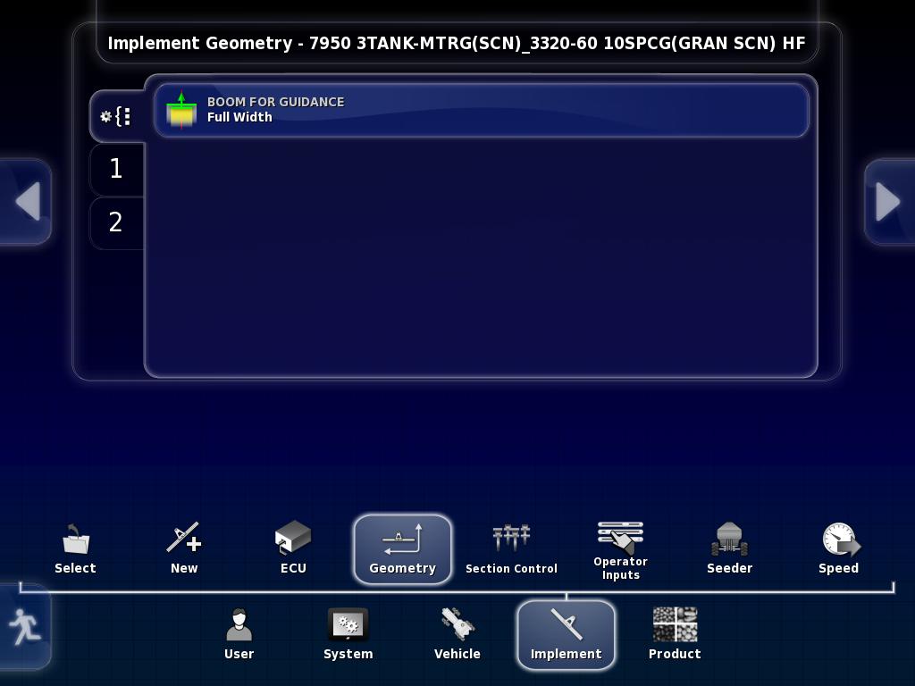
40 A - Swath Width - working width of the implement. B - Overlap - the width of the overlap between two adjacent swathes. It is mostly used for auto steer and guidance. This value is typically set to 0. C Not used D - Implement Wheels Offset - distance from pivot point of the drill to front row of openers. Enter: - negative number for standard machine as pivot point is back tires. - positive number for High Flotation machine as pivot point is front tires. E - Implement Offset - distance from the front hitch to pivot point of the drill. - regular drill, pivot point is back tires. - high flotation drill, pivot point is front tires. H - Working Length - depth of boom (distance from the front row of openers to the back row of openers).

41 Section Setup - Enter # of section and the width of each for the Multi-section boom - It can be set all the same or individually - If using multi-section the total width will auto Populate into the geometry screen

42 TIMING This will set times for product to get from the section control valves to the openers. 1. Select boom from the tabs on the left side, the name of that boom will be shown in the title bar. 2. ON time - it should be the time from when the section control valve opens until product is flowing at the exit of the opener. 3. OFF time - it should be the time from when the section control valve closes until product stops flowing at the exit of the opener. All sections can be set to have the same on/off time (the worst case) or they can have individual times for granular sections to have even less overlap. Since the product for the inner sections has less distance to travel they don't need to start as soon or stop as late so can have a shorter on/ off time. Note: please refer to the website for more on section control timing.
43 Section Switch - Enable a virtual switchbox so that you can manually control sections on screen - This virtual switchbox will show up on the guidance Page - Only works if your using sectional control

44 MASTER SWITCH - Virtual - use this selection if you do not have a cabin switchbox connected and only want the master switch to be controlled from the X30 console screen. - External Console Input - allows use of remote mapping connector on the X30 harness as an alternative master signal. - Apollo CM-40 - not used - Implement - use this selection if you want the auto clutch switch on your drill to act as the master switch Implement Master Switch - allows use of auto clutch as a secondary along with the other Master switch selection.
, select how you prefer to control tanks.")
45 KEYPAD This menu option will allow you to identify and assign the right in-cab and on-frame switchbox, assign functions to the buttons that have no functions assigned to them (A, B & C buttons), select how you prefer to control tanks. There are two tabs, one for the in-cab switchbox and the other for the switchbox on the frame of the air seeder.

46 GRANULAR SETUP Name as Bin or Tank - select Bin or Tank, depending on how you would like the individual compartments of your air seeder to be referred to. Use Product as Name - if enabled, name of the product that is assigned to the tank will be used as a name for that Bin/Tank. If no product assigned to the tank, the tank name will correspond to the tank number. Preload time this setting only effective for 7000 AS with hydraulic drive. This is time that meters will run when master is switched on while stationary Preload time is also the length of time that the meters will run when the prime button on the on-frame switchbox is pushed. Fan Speed to Start This prevents the possibility of running meters without fans engaged and subsequent plugging of the distribution pipes.
47 INDIVIDUAL TANK SETUP Name - here you can enter the name for the specific tank of the air seeder. Capacity - tank volume is factory preset and loaded from the implement profiles. Status - this setting will be shown only for the tanks which have drive assigned to them according to the air seeder tank model that was selected during the implement setup. Set status to "enable" if this tank will be metered from. Section Control (7000AS) - these settings appear only if granular section control is enabled in the profile. Sectional Boom: On Time to SC location - it should be the time from when meter starts until product is at the section valve. Off Time to SC location - it should be the time from when meter stops turning until product stop flowing through section valve. Full Width Boom: On Time to Ground - it should be the time from when meter starts until product is at the opener on longest run. Off Time to Ground - it should be the time from when meter stops turning until product stop flowing through the opener at shortest run. HINT: if tank is not being used disable it otherwise system won t allow you to start applying. All enabled tanks need a cal factor even if the switched off

48 Tank Grouping - Groupings are pre-set from the factory use the arrows on the right hand side to scroll though them - Tank volumes update automatically
49 Drive Setup - Toggle between the tanks with the tabs on the left Hand side - Drive type proportional for 7000 AS -linear for 6000 AS - Pulses/ Revolution 32 for 7000 AS 16 for 6000 AS - Minimum RPM set at 10 - Maximum RPM set at Metering Auger pick corresponding augers to each tank
 - Controller Response (medium")
50 Controller Settings - Minimum PWM (15%) - Maximum PWM (95%) - Controller Response (medium fast)
51 Tank Setup - Product Name enabled/disabled
52 Tank Setup - Name - can name each tank/bin - Capacity can be changed to match your tank - Status (enable/disable) if your not using one for a field Section Control - Available selections are Full Width and NH3/or Liquid. If using sectional control select NH3 or Liquid (the boom that is setup as sectional). If not using multi-section then select Full Width. On Time to Ground - it should be the time from when master is turned on until product is at the opener on longest run. Off Time to Ground - it should be the time from when master is turned off until product stops flowing through the opener at shortest run. Pump Speed (not used)

53 Flow Setup - Calibration Factor Can be set here or on the SRC screen - Flow Confirmation (not used)

54 PROPORTIONAL VALVE SETTINGS Flow Meter Sampling - Default setting is "standard". The optional "Reduced" sensitivity setting slows the reaction time of the proportional valve. This may be required for very low flow rates or if flow is highly irregular or worn equipment. Minimum/Maximum PWM - are the limits of the PWM (Pulse Width Modulation) drive and they vary with the type of drive. Min PWM: Is a percentage of voltage drive to the coil. Max PWM: Is a percentage of voltage drive to the coil. Controller Response - This will adjust how fast the controller will respond to changes. The default is set to Fastest. Dump Valve - Used to apply signal to a dump valve or master valve. - Enabled - applies power when tank is off. - Reversed - applies power when tank is on.

55 REGULATOR VALVE SETTINGS Flow Meter Sampling - Default setting is "standard". The optional "Reduced" sensitivity setting slows the reaction time of the regulator valve. This may be required for very low flow rates or if flow is highly irregular or worn equipment. Close Valve When Off- some regulating valves are a combination regulating and on/off valve, which means they must close when the tank is turned off Reverse Valve - this will allow for the polarity of the regulating motor of NH3 or liquid systems to be reversed if it was wired incorrectly. Dump Valve - Used to apply signal to a dump valve or master valve. - Enabled - applies power when tank is off. - Reversed - applies power when tank is on. Controller Mode - this is the controller model selection. Minimum On Time - is the minimum amount of time the controller will pulse the valve when it is trying to make a small correction. Maximum On Time - is the maximum amount of time that the controller will pulse the control valve before checking the rate. It is used to make a large correction for the rate. Gain Setting - is a software setting that either increases or reduces how hard the controller tries to stay on rate. The higher the Gain setting, the faster the valve responds. If this number is set too fast, it will lead to an overshoot, which then has to be corrected. PWM Setting - is the Pulse Width Modulation. Lowering this number reduces the voltage supplied to the valve, slowing it down.

56 Pressure Sensor Not Used
57 Fan Setup - Toggle though the different fans using the tabs On the left hand side - Fan speed disable if not using one of fans - Pulses (1)
58 Pump Speed Not Used

59 Not used this year Drill Control

60 Sensor Setup Don t need to touch if you have made a factor implement profile.

61 Blocked Head Monitor - Block head monitor (enabled/disabled) - Sensor Type (dickey - john) - Head monitoring Single/double shoot - Number of sensors 1 16 max - On the right hand you can name individual runs

62 Don t need to touch if you have made a factor implement profile.
63 GENERAL INPUTS This is an option that is related to other types of equipment and not used with Bourgault Air Seeders. Settings should be left disabled.

64 ENCODER Encoder settings designed for the technicians and can be accessed only if Access Level set to Dealer or Technician. Defaults are preassigned.

65 GENERAL OUTPUT This setting allows you to assign a relay output from one of the ECU drives. Not supported through Bourgault harnessing.
66 Speed setup Speed Source - allows user to select the speed source: GPS - to use GPS signal for speed. Wheel Sensor - to use wheel sensor on the air seeder tank for speed. Manual - to use custom manual speed entered in the Configuration panel on the Seeder Controller screen. Fallback Type In case the GPS signal is lost, to continue seeding, system will automatically switch to use speed source set in the Fallback Type. Wheel factor is pre-entered from the factory with a theoretical value and it represents the distance travelled by the seeder in the time between pulses from the ground speed sensor. The speed sensor is located on the rear left wheel, for 7000AS. For 6000AS it is located on a the transmission plate new the rear left wheel.
67 Not Used

68 New Product Setup Touch on the New product Bar to start
69 New Product setup - Pick Bourgault for our built in products list or Custom Products to build you own. This presentation will cover both. - Then click the side arrow to advance to the next screen
70 New Product setup - Scroll though the list of different product till you find the one you need. Click the product needed - Then click the side arrow to move to the next screen

71 New Product setup - You can click on the product name to change to what ever you like - Once finished click the side arrow to advance to the next screen
72 New Product Setup To finish it off press the green check mark

73 New Product Setup - You see the new product in your list. Now you can change and add information to the right hand side of the page - If you were unable to find the product that you need in our list you can go through and make a custom product. - Follow through the next couple slides on how to do that. - Start by touching the New Product icon.
74 Custom Product - Touch on custom Product then press the side arrow.
75 Custom Product This screen will prompt you to enter product name. Select Product Name button and keyboard screen will appear. Enter the product name and confirm. Select yellow arrow to proceed to the next step.
76 Custom Product This screen will prompt you to enter product density only if you are adding granular product, it is not required for liquid product.
77 Custom Products Rate Increment is used during operation to increase/decrease requested rate by preset value. Product Rate Preset 1 & 2 are preset rates, that are used to immediately adjust the application rate to that value during operation. Select Product Increment button, using numeric keypad enter required value and confirm. Repeat for Rate Preset 1 and Rate preset 2. Product setup is complete and next screen will prompt you to save product settings or cancel it,
78 Thank You
Dual Boom ASC Set-up
 Dual Boom ASC Set-up The Dual Boom ASC can be run with either the X30 or the X35. The compatible software versions for this on each monitor are 3.24.508 on the X30 and 4.01.508 on the X35. If you need
Granular Spinner Spreader Module Quick Reference Sheet
 Granular Spinner Spreader Module Quick Reference Sheet Section 1: Configuration Procedure The following procedure describes the complete process of configuring a granular spinner bed control system. To
SureFire Ag S 1.11A. 5.Select Application Type and Application Mode. 6. Set up Section Groups. Section Group 2 will start with Section
 396-3563Y1 QuickStart setup instructions for JDRC 2000 and SureFire harness for 2 Liquid/Dry Products 213-00-3453Y3 213-00-3538Y4 213-00-3467Y4 213-00-3585Y3 Below are typical SureFire Liquid Fertilizer
Y1. 5.Select Application Type and Application Mode. 6. Set up Section Groups. Section Group 2 will start with Section
 396-3563Y1 QuickStart setup instructions for JDRC 2000 and SureFire harness for 2 Liquid/Dry Products 213-00-3453Y1 213-00-3538Y1 213-00-3467Y1 213-00-3585Y1 Below are typical SureFire Liquid Fertilizer
Y1. QuickStart setup instructions for JDRC 2000 and SureFire harness for 1 Liquid/Dry Product Y Y Y3 1.
 396-3562Y1 Below are typical SureFire Liquid Fertilizer System setup screens. Your setup may vary. Not all screens are shown. See the John Deere Operator s Manual for safety information and additional
IOP:018.4 U.S. Fish and Wildlife Service INSTRUMENT OPERATING PROCEDURE
 IOP:018.4 January 9, 2017 U.S. Fish and Wildlife Service Marquette Biological Station 3090 Wright Street Marquette, Michigan 49855 U.S.A. and U.S. Fish and Wildlife Service Ludington Biological Station
Installation Guide. Suitable for: OEM Integration OEM Installation Retro Fit Installation
 Installation Guide Suitable for: OEM Integration OEM Installation Retro Fit Installation DTI AngleBlaster release 1.1 DTI 2010 Overview Angleblaster Installation Guide A-1 To obtain the best accuracy from
INSTRUCTION MANUAL FOR ULTRASONIC/MICROWAVE SENSORS
 INSTRUCTION MANUAL FOR ULTRASONIC/MICROWAVE SENSORS 1)Install PROBE_GatewayPC Software on PC.Remove previous installation. In Windows Control Panel go to the Programs and Features, select Probe_GatewayPC_Net
DirectCommand TM Spreader
 Create Configuration Application Start of Configuration Wizard Enter Settings Configuration Application Press to Highlight Configuration 4930rx calibrate fan frame feed gate Product Controller Settings
Calibration Instruction Manual Emerson 475 Field Communicator. Manual Revision FC.2
 Calibration Instruction Manual Emerson 475 Field Communicator Manual Revision FC.2 ABM 2 Wire Radar with HART ABM Sensor Technologies Inc 2013, all rights reserved. Emerson is a registered trademark of
Happy Link Software INSTRUCTION MANUAL
 Happy Link Software INSTRUCTION MANUAL 101001E-3 HAPPY Contents Regarding this software Normal Operation -------------------------------------------------------------------------------------------------
QUICK START GUIDE. AStrO. Ver Toll Free : 1 (877) Visit :
 Visit :") QUICK START GUIDE AStrO Ver.10.309 Toll Free : 1 (877) 462-7296 Visit : 1 Thank you for purchasing the latest in data acquisition technology, the AStrO. We hope that it surpasses your expectations. This
QUICK START GUIDE AStrO Ver.10.309 Toll Free : 1 (877) 462-7296 Visit : 1 Thank you for purchasing the latest in data acquisition technology, the AStrO. We hope that it surpasses your expectations. This
FIRST Robotics Control System
 2018/2019 FIRST Robotics Control System Team 236 1 (click on a component to go to its slide) 2 The Robot Powered solely by 12V battery RoboRIO- is the computer on the robot Controlled by Java code on the
ET Water SmartWorks Panel Installation Guide
 ET Water SmartWorks Panel Installation Guide You are installing a new piece of equipment that retrofits into an existing irrigation controller in order to create a weather-based irrigation control system.
HPVFP High Performance Full Function Vector Frequency Inverter
 Advanced User Manual HPVFP High Performance Full Function Vector Frequency Inverter HP VER 1.00 1. HPVFP Parameter Set Overview...3 1.1. About this section...3 1.2. Parameter Structure Overview...3 1.3.
BATCHMATE 1500 Batch Control Computer Technical Bulletin
 TS-5(C) BATCHMATE 5 Batch Control Computer Technical Bulletin DESCRIPTION The BATCHMATE features an 8 digit.55-in. alphanumeric LED display. The pulse input model will accept up to 2, pulses per second
MAXYM Mortiser Operating Manual
 MAXYM Mortiser Operating Manual Rev 2.112/16/02 Copyright MAXYM Technologies Inc. Table of Contents Visual Tour 1-2 Operating the Maxym Mortiser 3 Starting the Mortiser 3 Touch Screen Description 3 Mortise
AutoCAD Tutorial First Level. 2D Fundamentals. Randy H. Shih SDC. Better Textbooks. Lower Prices.
 AutoCAD 2018 Tutorial First Level 2D Fundamentals Randy H. Shih SDC PUBLICATIONS Better Textbooks. Lower Prices. www.sdcpublications.com Powered by TCPDF (www.tcpdf.org) Visit the following websites to
Convey-All BTS 550 Wireless Seed Tender Remote Users Manual
 Convey-All BTS 550 Wireless Seed Tender Remote Users Manual Intercomp Co. 3839 County Road 116 Medina, MN 55340, U.S.A. (763)-476-2531 1-800-328-3336 Fax: 763-476-2613 www.intercompcompany.com Manual#
Operating Rausch ScanCam within POSM.
 Operating Rausch ScanCam within POSM. POSM (Pipeline Observation System Management) // posmsoftware.com // info@posmsoftware.com // 859-274-0041 RAUSCH USA // www.rauschusa.com // reusa@rauschusa.com //
MATRIX 430. Entry level guidance Software version 1.03
 MATRIX 430 U S E R M A N U A L Entry level guidance Software version 1.03 GETTING STARTED 1. Power on the console. Setup machine 2. On guidance screen, press NAVIGATION AND GUIDANCE OPTIONS tab to display
Q Panel General Guide
 Q Panel General Guide Contents Q Panel General Guide Welcome to Q Experience! Available applications Tech overview Overview Quick Start Applications Elements: Sidebar Sidebar: Modes Elements: Main menu
Use the and buttons on the right to go line by line, or move the slider bar in the middle for a quick canning.
 How To Use The IntelliQuilter Help System The user manual is at your fingertips at all times. Extensive help messages will explain what to do on each screen. If a help message does not fit fully in the
Manual BC20 Control Service Guide
 Manual BC20 Control Service Guide To Access the following menus, with the in the OFF mode, press and hold the upper encoder (Timer Knob) until "0000" appears. Then turn the encoder till the first number
Instruction Manual. gizzmo. Real Performance Product By GIZZMO
 Real Performance Product By GIZZMO Thank you for purchasing the Gizzmo IBC-R RPM dependent Boost Controller Boost Controller. This manual contains operating instructions and installation procedures that
Contents STARTUP MICROSCOPE CONTROLS CAMERA CONTROLS SOFTWARE CONTROLS EXPOSURE AND CONTRAST MONOCHROME IMAGE HANDLING
 Operations Guide Contents STARTUP MICROSCOPE CONTROLS CAMERA CONTROLS SOFTWARE CONTROLS EXPOSURE AND CONTRAST MONOCHROME IMAGE HANDLING Nikon Eclipse 90i Operations Guide STARTUP Startup Powering Up Fluorescence
GreenStar Display Measuring Offsets PC21926
 Display Measuring Offsets PC21926 Machine Offsets Row Crop Tractor A or 1) Center of GPS Receiver to Center line of Machine Applications requiring this setting include: Guidance Section Control Mapping
Instruction Manual ABM HART Gateway Software. Instruction Manual Revision A.1
 Instruction Manual ABM HART Gateway Software Instruction Manual Revision A.1 Table of Contents Section 1: Getting Started... 3 1.1 Setup Procedure... 3 1.2 Quick Setup Guide for Ultrasonic Sensors... 11
About the DSR Dropout, Surge, Ripple Simulator and AC/DC Voltage Source
 About the DSR 100-15 Dropout, Surge, Ripple Simulator and AC/DC Voltage Source Congratulations on your purchase of a DSR 100-15 AE Techron dropout, surge, ripple simulator and AC/DC voltage source. The
Model # PCYFC-10kW-250A PCYFC-20kW-250A PowerCycle Battery Conditioner Operation Manual
 Model # PCYFC-10kW-250A PCYFC-20kW-250A PowerCycle Battery Conditioner Operation Manual MAN-000014-00 REV. B TABLE OF CONTENTS SPECIFICATIONS... 1 CYCLER CONTROLS AND USER INTERFACE... 3 OPERATING PROCEDURE...
FSP-211 DIGITAL HIGH/LOW PIR FIXTURE INTEGRATED SENSOR
 FSP-211 DIGITAL HIGH/LOW PIR FIXTURE INTEGRATED SENSOR CAUTIONS INSTALLATION INSTRUCTIONS IMPORTANT SAFEGUARDS When using electrical equipment, basic safety precautions should always be followed including
Warehouse Instruction Guide
 Warehouse Instruction Guide Review Equipment & Supplies page 2 Set-Up Access Point page 6 Register Scanners page 8 Place Fixture Stickers/Enter Ranges page 10 Scanning Basics and Additional Keyboard Functions
NOLTING LONGARM QUILTING MACHINES. The originator of longarm quilting machines since the 1970's
 NOLTING LONGARM QUILTING MACHINES The originator of longarm quilting machines since the 1970's Congratulations on the purchase of your new Nolting NV! NEW! The highest performance and most features are
EOS 80D (W) Wireless Function Instruction Manual ENGLISH INSTRUCTION MANUAL
 Wireless Function Instruction Manual ENGLISH INSTRUCTION MANUAL") EOS 80D (W) Wireless Function Instruction Manual ENGLISH INSTRUCTION MANUAL Introduction What You Can Do Using the Wireless Functions This camera s wireless functions let you perform a range of tasks wirelessly,
EOS 80D (W) Wireless Function Instruction Manual ENGLISH INSTRUCTION MANUAL Introduction What You Can Do Using the Wireless Functions This camera s wireless functions let you perform a range of tasks wirelessly,
EULAMBIA ADVANCED TECHNOLOGIES LTD. User Manual EAT-EOM-CTL-2. Alexandros Fragkos
 EULAMBIA ADVANCED TECHNOLOGIES LTD User Manual Alexandros Fragkos (alexandros.fragkos@eulambia.com) 11/28/2016 28/11/2016 User Manual User Manual 28/11/2016 Electro-Optic Modulator Bias Control Unit v2.0
Trimble FMX/FM with Hydraulic Steer - Trimble Aftermarket. Installation & Configuration Guide for Harness :
 Trimble FMX/FM 1000 - with Hydraulic Steer - Trimble Aftermarket Installation & Configuration Guide for Harness 725599: Summary: In order for 20/20 SeedSense Monitor to receive NMEA strings from a third
SYNGUIDER USER'S MANUAL
 SYNGUIDER USER'S MANUAL GETTING STARTED PREPARING THE SYNGUIDER BASIC OPERATIONS OPERATION UNDER THE NIGHT SKY SPECIFICATIONS 1 3 4 9 15 060613V1 Thank you for choosing the SynGuider. The SynGuider can
AutoCAD LT 2009 Tutorial
 AutoCAD LT 2009 Tutorial Randy H. Shih Oregon Institute of Technology SDC PUBLICATIONS Schroff Development Corporation www.schroff.com Better Textbooks. Lower Prices. AutoCAD LT 2009 Tutorial 1-1 Lesson
Blue Point Engineering
 Blue Point Engineering Instruction I www.bpesolutions.com Pointing the Way to Solutions! Animatronic Wizard - 3 Board (BPE No. WAC-0030) Version 3.0 2009 Controller Page 1 The Wizard 3 Board will record
Hagie STS/DTS (2018 & Newer)
") Hagie STS/DTS (2018 & Newer) ISO Liquid Kit PN: 2006486 REV. B Table of Contents Introduction... 3 Important Information... 3 Preliminary Installation Requirements... 3 Trademark... 3 Technical Support...
Hagie STS/DTS (2018 & Newer) ISO Liquid Kit PN: 2006486 REV. B Table of Contents Introduction... 3 Important Information... 3 Preliminary Installation Requirements... 3 Trademark... 3 Technical Support...
ET2000e IRRIGATION CONTROLLER
 ET2000e PROGRAMMING GUIDE ET2000e IRRIGATION CONTROLLER PROGRAMMING GUIDE For use with ET2000e irrigation controllers running on firmware version 605.a and above. CHANGE 1 INCORPORATED 30 March 2007 TABLE
AEROS Software version 4.32
 AEROS 9040 U S E R G U I D E Software version 4.32 Table of Contents START SIMPLE GUIDANCE 1 #1 POWER ON 1 #2 HOME SCREEN 1 System Setup...1 RealView Camera Full Screen Video View...1 ISOBUS Universal
SDC. AutoCAD LT 2007 Tutorial. Randy H. Shih. Schroff Development Corporation Oregon Institute of Technology
 AutoCAD LT 2007 Tutorial Randy H. Shih Oregon Institute of Technology SDC PUBLICATIONS Schroff Development Corporation www.schroff.com www.schroff-europe.com AutoCAD LT 2007 Tutorial 1-1 Lesson 1 Geometric
HT101V Reference Manual
 HT101V Reference Manual Overview The HT101V from Ag-Tester is our handheld tester designed to diagnose valve components on agricultural machinery. Valves tested include: 1- Boom Control Valves 2- Servo
Addendum to HQ 24 Fusion User Manual
 Addendum to HQ 24 Fusion User Manual The touch screen display photographed in the manual may be different from the one you received with your HQ 24 Fusion. These pages replace portions of the printed HQ
Addendum SmartPAC Third Party Communications Firmware
 Addendum SmartPAC Third Party Communications Firmware The SmartPAC Third Party Communications Firmware option enables SmartPAC 2 and the original SmartPAC to transmit real-time and status information to
BERNINA Sewing Machine Workbook 3
 my BERNINA Sewing Machine Workbook 3 Creative Options For BERNINA 880, 7 Series, 580, 570 QE, 560 (Pages 8-12: B 790, 880 only; Pages 13-15: B 880 only) 2016 BERNINA of America. Permission granted to copy
Nebraska 4-H Robotics and GPS/GIS and SPIRIT Robotics Projects
 Name: Club or School: Robots Knowledge Survey (Pre) Multiple Choice: For each of the following questions, circle the letter of the answer that best answers the question. 1. A robot must be in order to
DXXX Series Servo Programming...9 Introduction...9 Connections HSB-9XXX Series Servo Programming...19 Introduction...19 Connections...
 DPC-11 Operation Manual Table of Contents Section 1 Introduction...2 Section 2 Installation...4 Software Installation...4 Driver Installastion...7 Section 3 Operation...9 D Series Servo Programming...9
ATS-I USER MANUAL. Tecnoelettra srl Dal Via Vioni Dimo, S.Rocco di Guastalla (RE)
") USER MANUAL ATS-I Tel.+39.0522.832004 P1/17 ATS-I User manual Fax.+39.0522.832012 Tecnoelettra_EN.doc P.1/17 Index General description...3 Electrical specifics...3 Device operative logic...4 Manual mode...4
USER MANUAL ATS-I Tel.+39.0522.832004 P1/17 ATS-I User manual Fax.+39.0522.832012 Tecnoelettra_EN.doc P.1/17 Index General description...3 Electrical specifics...3 Device operative logic...4 Manual mode...4
Table of Contents. Chapter 3. The 843-R Power Meter Unit.. 17
 Table of Contents Chapter 1. Introduction: How to Use This Manual... 3 Chapter 2. Quick Reference... 4 2.1 Getting Started... 4 2.2 Functions with No Sensor Connected... 5 2.3 Thermal Sensors... 8 2.4
SpeedTube Operations Manual
 SpeedTube Operations Manual 955424_01 2/16 1 Contents SpeedTube Setup... 3 Swath Calibration... 5 SpeedTube Operation... 6 Vacuum Setting... 6 Good Ride Metric... 7 SpeedTube Diagnostics... 7 SpeedTube
Creative Options For BERNINA 8 Series, models 780, and 580 (Pages 1-8 also apply to models 710 & 750QE)
") Creative Options For BERNINA 8 Series, models 780, and 580 (Pages 1-8 also apply to models 710 & 750QE) 2012 BERNINA of America, Inc. Permission granted to copy and distribute in original form only. Content
Creative Options For BERNINA 8 Series, models 780, and 580 (Pages 1-8 also apply to models 710 & 750QE) 2012 BERNINA of America, Inc. Permission granted to copy and distribute in original form only. Content
5008 Dual Synthesizer Configuration Manager User s Guide (admin Version) Version valontechnology.com
 Version valontechnology.com") 5008 Dual Synthesizer Configuration Manager User s Guide (admin Version) Version 1.6.1 valontechnology.com 5008 Dual Synthesizer Module Configuration Manager Program Version 1.6.1 Page 2 Table of Contents
5008 Dual Synthesizer Configuration Manager User s Guide (admin Version) Version 1.6.1 valontechnology.com 5008 Dual Synthesizer Module Configuration Manager Program Version 1.6.1 Page 2 Table of Contents
AutoCAD LT 2012 Tutorial. Randy H. Shih Oregon Institute of Technology SDC PUBLICATIONS. Schroff Development Corporation
 AutoCAD LT 2012 Tutorial Randy H. Shih Oregon Institute of Technology SDC PUBLICATIONS www.sdcpublications.com Schroff Development Corporation AutoCAD LT 2012 Tutorial 1-1 Lesson 1 Geometric Construction
Operator Manual 1.4 FRACSIM MINI
 FracSim Meters FracSim Meters was founded with the intention of providing specifically designed tools for the well service industry. Our goal is to provide quality tools with a robust design to meet the
OVEN INDUSTRIES, INC. Model 5C7-362
 OVEN INDUSTRIES, INC. OPERATING MANUAL Model 5C7-362 THERMOELECTRIC MODULE TEMPERATURE CONTROLLER TABLE OF CONTENTS Features... 1 Description... 2 Block Diagram... 3 RS232 Communications Connections...
RISK OF SHOCK: DO NOT WIPE DOWN ANY ELECTRICAL COMPONENTS. ALWAYS KEEP AWAY FROM ALL AREAS WHERE ELECTRONIC COMPONENTS ARE INSTALLED.
 Maintenance General Cleaning Waste material from the printing process can accumulate inside the printer. Using a slightly damp, lint-free cloth, wipe the interior of the CubePro including the print plate,
Electronic regulator for PWM controlled proportional solenoid valves FABER -
 Electronic regulator for PWM controlled proportional solenoid valves STU Control Unit FABER - COM DESCRIPTION STU-PWM electronic card is a regulator for proportional solenoid valves, which can drive up
IMPORTANT SAFEGUARDS READ AND FOLLOW ALL SAFETY INSTRUCTIONS SAVE THESE INSTRUCTIONS FOR FUTURE REFERENCE
 FSP-2X1 Digital High/Low Pir Fixture Integrated Sensor INSTALLATION INSTRUCTIONS IMPORTANT SAFEGUARDS When using electrical equipment, basic safety precautions should always be followed including the following:
Alemite FCS Fluid Control System
 343000 343000-1 Alemite FCS Fluid Control System Installation and Operation Guide 670996 TABLE OF CONTENTS DISCLAIMER... 3 BEFORE YOU BEGIN........................................................ 4 1.0
Online - Display and CommandARM TM Simulator. Help Guide
 Online - Display and CommandARM TM Simulator Help Guide GS2 1800 Display GS3 CommandCenter TM Display GS3 2630 Display Generation 4 CommandCenter TM Display Last Updated: January 2017 Applies to Online
UWYO VR SETUP INSTRUCTIONS
 UWYO VR SETUP INSTRUCTIONS Step 1: Power on the computer by pressing the power button on the top right corner of the machine. Step 2: Connect the headset to the top of the link box (located on the front
Lucky Leprechaun. 1. Overview. Game Rules (v1.2-28/06/2016) The goal is to obtain a winning combination on a winning line spread across the reels.
 The goal is to obtain a winning combination on a winning line spread across the reels.") Lucky Leprechaun Game Rules (v1.2-28/06/2016) 1. Overview The goal is to obtain a winning combination on a winning line spread across the reels. Game specifications: Type Slots Number of reels 5 Number
Lucky Leprechaun Game Rules (v1.2-28/06/2016) 1. Overview The goal is to obtain a winning combination on a winning line spread across the reels. Game specifications: Type Slots Number of reels 5 Number
Agxcel GX10 Integration into Raven 440/450/540. AgXcel. GX10 Raven Integration 440/450/540 Version 2.0
 Agxcel GX10 Integration into Raven 440/450/540 Installation Overview These instructions cover AgXcel Integration kit installation for Raven 440/450 Sprayer Control Systems (Raven SCS) for liquid applications.
Firmware Version d & higher Installation & Operation
 DIGI LCD Readout Firmware Version d 2.100 & higher Installation & Operation READOUT SERIAL # SCALE SERIAL # TO MAXIMIZE THE ACCURACY OF YOUR SYSTEM, THE FOLLOWING PROGRAMMING PARAMETER HAS BEEN PRE-CONFIGURED
MA7200 PLUS INVERTER SERIES PID Quick Start Manual For Fan and Pump Applications
 MA7200 PLUS INVERTER SERIES PID Quick Start Manual For Fan and Pump Applications 3 to 75 HP Models- MA7200-2003-N1 Thru MA7200-2040-N1 (230V) & MA7200-4003-N1 Thru MA7200-4075-N1 (460V) speed time Rev.
RD1000 Ground Probing Radar
 RD1000 Ground Probing Radar CONTENTS Product Introduction Product Features Competitor Analysis Customers Models, Pricing & Availability Promotional Material Practical Demonstration What to do now Summary
Relay Driver Overview and Applications
 Relay Driver Overview and Applications Describes Basic and Advanced Settings for common and alternative/novel uses for the Relay driver (RD-1). Morningstar s Relay Driver (RD-1) is a fully programmable
Y1. Troubleshooting / Service Guide for SureFire PWM Liquid Application Systems. John Deere Rate Controller 2000
 396-3613Y1 Troubleshooting / Service Guide for SureFire PWM Liquid Application Systems John Deere Rate Controller 2000 Always verify the controller settings. See the screenshots in Section F of the system
SCOUT Mobile User Guide 3.0
 SCOUT Mobile User Guide 3.0 Android Guide 3864 - SCOUT February 2017 SCOUT Mobile Table of Contents Supported Devices...1 Multiple Manufacturers...1 The Three Tabs of SCOUT TM Mobile 3.0...1 SCOUT...1
SATELLITE RADIO/TELEPHONE
 A Unique and Powerful Communications System NETWORK INNOVATIONS SATELLITE RADIO/TELEPHONE (FORMERLY SKYTERRA, MSV, LIGHT SQUARED ) Secure Communications 1. The network employs the IMBE (Improved Multi-Band
Quick Start Guide for the PULSE PROFILING APPLICATION
 Quick Start Guide for the PULSE PROFILING APPLICATION MODEL LB480A Revision: Preliminary 02/05/09 1 1. Introduction This document provides information to install and quickly start using your PowerSensor+.
ADMS-847 Programming Software for the Yaesu FT-847
 for the Yaesu FT-847 Memory Types Memories Limit Memories VFO A VFO B Home Satellite Memories One Touch Memory Channel Functions Transmit Frequency Offset Frequency Offset Direction CTCSS DCS Skip The
FAG PRESTO DX. FAG PRESTO-DX preliminary User Manual. FAG GRAPHIC SYSTEMS S.A. 3, rue de la Vigie CH-1003 Lausanne Switzerland
 FAG PRESTO DX FAG PRESTO-DX preliminary User Manual Table of Contents Safety Instructions... 4 DECLARATION OF CONFORMITY... Erreur! Signet non défini. PRESTO DX... 5 Pass Fail Indicator... 6 RESET and
with MultiMedia CD Randy H. Shih Jack Zecher SDC PUBLICATIONS Schroff Development Corporation
 with MultiMedia CD Randy H. Shih Jack Zecher SDC PUBLICATIONS Schroff Development Corporation WWW.SCHROFF.COM Lesson 1 Geometric Construction Basics AutoCAD LT 2002 Tutorial 1-1 1-2 AutoCAD LT 2002 Tutorial
COMAND Operator, s Manual
 Order-No. DaimlerChrysler 6515 6635 13 Blaupunkt 8 622 402 630 Index B Parts-No. 203 584 01 93 USA Edition A 2002 203/463 Operator, s Manual COMAND COMAND Operator, s Manual As a result of new improvements
BandMaster V Manual. Installation
 BandMaster V Manual Installation Installing and configuring the BM-5 BandMaster V is a simple process. All the configuration process is done from the front panel. Installation and configuration steps are
QAM Snare Navigator Quick Set-up Guide- GSM version
 QAM Snare Navigator Quick Set-up Guide- GSM version v1.0 3/19/12 This document provides an overview of what a technician needs to do to set up and configure a QAM Snare Navigator GSM version for leakage
Firmware Version d & higher Installation & Operation
 DIGI LCD Readout Firmware Version d 2.100 & higher Installation & Operation Warranty Accurate Technology, Inc., warrants this product against defective parts and workmanship for 1 year commencing from
FRUIT BONUS 2 nd Generation 2004 AMCOE INC.
 PIN PARTS SIDE SOLDER SIDE PIN 1 VIDEO RED VIDEO GREEN 1 2 VIDEO BLUE VIDEO SYNC 2 3 SPEAKER + SPEAKER - 3 4 EXTRA - 4 5 EXTRA - STOP 2 EXTRA - ALL STOP 5 6 EXTRA - STOP 3 6 7 TICKET OUT BUTTON - panel
Operating Instructions Pocket Pictor For use with Pocket Pc s
 Introduction Operating Instructions Pocket Pictor For use with Pocket Pc s The compact size and low power consumption of Pocket PC s make them ideal for use in the field. Pocket Pictor is designed for
CS-200. PORTABLE TRAFFIC LIGHT CONTROLLER (Software 1.05) OPERATION AND SERVICE MANUAL
 OPERATION AND SERVICE MANUAL") CS-200 PORTABLE TRAFFIC LIGHT CONTROLLER (Software 1.05) OPERATION AND SERVICE MANUAL CS-200 Operation and Service Manual Page 2 Manufactured by: LINCAST INTERNATIONAL PTY. LTD. 2/3 Sir Laurence Drive
CS-200 PORTABLE TRAFFIC LIGHT CONTROLLER (Software 1.05) OPERATION AND SERVICE MANUAL CS-200 Operation and Service Manual Page 2 Manufactured by: LINCAST INTERNATIONAL PTY. LTD. 2/3 Sir Laurence Drive
Océ User manual. Océ CS4300 scanner series User Manual Océ CS4300 scanner series
 Océ User manual Océ CS4300 scanner series User Manual Océ CS4300 scanner series o Océ-Technologies B.V. 2008, Océ-Technologies B.V. Venlo, The Netherlands. All rights reserved. No part of this work may
The CO2 Sensor Calibration Kit
 The CO2 Sensor Kit For use with all BAPI CO 2 Sensors Instruction Manual CO 2 Kit Product Identification and Overview BAPI s CO 2 Sensor Kit is designed to calibrate and verify the operation of all BAPI
AUTO CAL II PO Box Sta Safety Road Houma, LA Tel # Fax #
 AUTO CAL II PO Box 10083 Sta. 1 233 Safety Road Houma, LA 70363 Tel # 985-868-1477 Fax # 985-879-1617 e-mail - autocalflow@aol.com www.autocalflow.com Operating Instructions American System SW 1 SW 2 SW
WLDS-10 Mk2 MAJOR WATER LEAK DETECTION SYSTEM INSTALLATION & COMMISSIONING
 WLDS-10 Mk2 MAJOR WATER LEAK DETECTION SYSTEM INSTALLATION & COMMISSIONING DESCRIPTION: An electronic control panel used in conjunction with one pulse meter (a water meter with pulse output proportional
Changing settings in the BlueSolar MPPT Charge Controllers
 2016-11-21 07:40 1/14 Changing settings in the BlueSolar MPPT Charge Controllers Changing settings in the BlueSolar MPPT Charge Controllers DEPRECATED: Use VictronConnect instead of mpptprefs We recommend
Studuino Icon Programming Environment Guide
 Studuino Icon Programming Environment Guide Ver 0.9.6 4/17/2014 This manual introduces the Studuino Software environment. As the Studuino programming environment develops, these instructions may be edited
MFJ ENTERPRISES, INC.
 Screwdriver Antenna Controller Model MFJ-1926 INSTRUCTION MANUAL CAUTION: Read All Instructions Before Operating Equipment! MFJ ENTERPRISES, INC. 300 Industrial Park Road Starkville, MS 39759 USA Tel:
Nikon Firmware Update for Coolpix 950 Version 1.3
 Nikon Firmware Update for Coolpix 950 Version 1.3 Notes: 1. It is most important that you follow the supplied directions; failure to follow all of the steps may result in your camera being disabled. 2.
Automatic Tool Changer (ATC) for the prolight A Supplement to the prolight 1000 User s Guide
 for the prolight A Supplement to the prolight 1000 User s Guide") Automatic Tool Changer (ATC) for the prolight 1000 A Supplement to the prolight 1000 User s Guide 1 1995 Light Machines Corporation All rights reserved. The information contained in this supplement (34-7221-0000)
Automatic Tool Changer (ATC) for the prolight 1000 A Supplement to the prolight 1000 User s Guide 1 1995 Light Machines Corporation All rights reserved. The information contained in this supplement (34-7221-0000)
Ag Leader EZ-Guide Quick Reference Card
 g Leader EZ-Guide Step 1: GPS antenna a. Mount the antenna on the highest part of the vehicle. Ensure that there are no obstructions in the way of the GPS antenna. b. Mount the antenna along the boom centerline
USER MANUAL. EPP Intelligent Positioner Control Unit 1/22.
 USER MANUAL - Intelligent Positioner Control Unit 1/22 Table of contents: 1 General... 3 1.1 Safety instructions... 3 2 Application... 4 3 Electrical specifications and terminals... 5 3.1 Control loop...
Uniden BCD396T Firmware Revision Notes
 Uniden BCD396T Firmware Revision Notes 1.20.13 As part of Uniden s commitment to the continued support of the BCD396T, Uniden has, from time to time, issued firmware updates. These updates contain major
WARRANTY. Long Range Systems, LLC, 20 Canal St, Suite 4N, Franklin, NH 03235
 WARRANTY Long Range Systems, Inc. warrants the trap release product against any defects that are due to faulty material or workmanship for a one-year period after the original date of consumer purchase.
2016 Motorized Shades Basic Programming
 About Motorized Shades: 2016 Motorized Shades Basic Programming A. THE (DUAL VOLTAGE) TWO WIRE 25TE MOTOR REQUIRES 120V AC OR 240V AC. B. BATTERIES ARE (NOT INCLUDED) FOR 12V 25CE BATTERY MOTORS. EACH
AZATOM SONANCE T1 Digital Radio. DAB+/DAB/FM Radio Alarm Clock. User Manual. This manual is available to download online at
 AZATOM SONANCE T1 Digital Radio DAB+/DAB/FM Radio Alarm Clock User Manual This manual is available to download online at www.azatom.com Thank you for shopping with AZATOM Please read this manual carefully
STRUCTURE SENSOR QUICK START GUIDE
 STRUCTURE SENSOR 1 TABLE OF CONTENTS WELCOME TO YOUR NEW STRUCTURE SENSOR 2 WHAT S INCLUDED IN THE BOX 2 CHARGING YOUR STRUCTURE SENSOR 3 CONNECTING YOUR STRUCTURE SENSOR TO YOUR IPAD 4 Attaching Structure
Reference Guide Brief explanations for routine operations
 Reference Guide Brief explanations for routine operations DCP-T30 DCP-T50W DCP-T70W Brother recommends keeping this guide next to your Brother machine for quick reference. Online User's Guide For more