Başkent University Department of Electrical and Electronics Engineering EEM 311 Electronics II Experiment 8 OPERATIONAL AMPLIFIERS
|
|
|
- Rosanna Ward
- 5 years ago
- Views:
Transcription
1 Başkent University Department of Electrical and Electronics Engineering EEM 311 Electronics II Experiment 8 Objectives: OPERATIONAL AMPLIFIERS 1.To demonstrate an inverting operational amplifier circuit. 2.To demonstrate the use of operational amplifiers for performing mathematical operations integration and differentation. Discussion: The operational amplifier is probably the most frequently used linear integrated circuit available. Applications for operational amplifiers range from the simple voltage amplifiers discussed in this experiment to complex circuitry that is beyond the scope of this course. The amplifier configurations investigated in this experiment are the basic building blocks of modern electronic circuits. There are two basic configurations for operational amplifier circuits: the inverting amplifier and the noninverting amplifier. Operational amplifiers ideally have infinite open-loop gain and infinite openloop input resistance. Open-loop characteristics refer to those of an amplifier having no feedback resistance between output and input. Closed-loop characteristics are those of an amplifier having an external feedback resistor. The resistor provides negative feedback, whereby a portion of the output voltage is subtracted from the input. Both the inverting and noninverting amplifier use the principle of negative feedback to control the overall (closed-loop) voltage gain. Figure 1 shows a typical inverting amplifier configuration. An ideal inverting amplifier s voltage gain is determined by: where: R1 is the input resistor RF is the feedback resistor As usual, the minus sign signifies phase inversion. As shown in Figure A, the output of an electronic integrator is proportional to the total area under the input waveform up to that point in time. To perform integration, a capacitor is connected in the feedback path of the amplifier. However, any DC voltage appearing at the input of an integrator will cause the output voltage to rise (or fall) until it reaches its maximum (or minimum) possible value. To
2 prevent this undesirable occurence, a ressitor, RF, is connected in parallel with the feedback capacitor. Any DC input voltage, such as the input offset voltage of the amplifier, is then simply amplified by the DC gain, RF/R1. The following equation can be used to determine the output voltage of the op-amp integrator with a sine wave input: integrator differentiator Figure A Integration will be performed only at frequencies well above the break frequency caused by the feedback resistor:
3 As shown in Figure A, the output of an electronic differentiator is proportional to the rate-ofchange of input waveform at any point in time. To perform differentiation, a capacitor is connected in series with the input. The following equation can be used to determine the output voltage of the op-amp differentiator with a sine wave input: Since the output voltage of a differentiator is proportional to the input frequency, high- frequency signals (such as electrical noise) may saturate or cutoff the amplifier. For this reason, a resistor is placed in series with the capacitor in the input. This establishes a high-frequency limit beyond which differentiation no longer occurs: To achieve greater attenuation at higher frequencies (to prevent oscillation), a feedback capacitor is added in parallel with the feedback resistor. This establishes another break frequency that can be calculated like the one in the integrator. Procedure: 1. To investigate an operational amplifier used as an inverting amplifier, connect the circuit in Figure 1.The small numbers in the diagram correspond to the integrated circuit s (chip s) pin numbers, as shown in specification sheets. (NOTE: If oscillation occurs it may be necessary to add 0.1 µf capacitors from each supply pin to ground. Also keep this in mind when performing all future op-amp experiments.) Figure 1
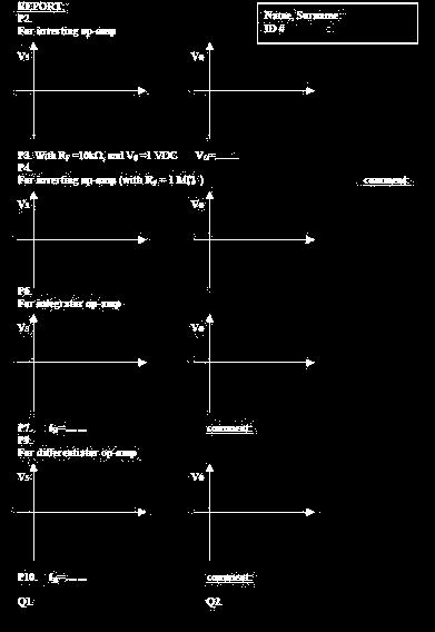
4 2. Connect a dual-trace oscilloscope to observe both the input VS =100 1 khz, and the output voltage VO draw the input and output waves in report. Also note,for an indicated value, the phase angle of the output VO with respect to the input VS. (Use a 4.7 KΩ resistor for RF for this step) 3.To verify that the inverting amplifier is a dc amplifier, replace the signal generator with a dc power supply. With RF =10kΩ, and VS =1 VDC measure the output voltage VO and note its polarity with respect to VS. 4.Now replace RF with a 1 MΩ resistor and sketch the resulting output waveform VO as well as the input waveform VS. What is your comment for that situation. 5.To investigate the use of an operational amplifier to perform mathematical integration, connect the circuit in Figure 2. Figure 2
5 6. With VS adjusted to produce a ± 5 V peak square 100 Hz. Using a dual-trace oscilloscope, sketch the output voltage Vo graph and the input voltage Vs graph to the report indicated values must be shown on graph- 7.Find break frequency, fb for integrator which is formulated in discussion part. Change the frequency to 20 Hz, what happens? Then change the frequency to 1 KHz, what happens? 8.To investigate the use of an operational amplifier to perform mathematical differentiation, connect the circuit in Figure 3. 9.With VS adjusted to produce a ± 1 V peak square 200 Hz. Using a dual-trace oscilloscope, sketch the output voltage Vo graph and the input voltage Vs graph to the report indicated values must be shown on graph- 10.Find break frequency, fb for differentiator which is formulated in discussion part. Change the frequency to 500 Hz, what happens? Then change the frequency to 100 Figure3 Questions: 1.What are the results of integrator and differentiator op-amp circuit experiments. Do they really work? 2.What is the phase difference between Vs and Vo for an inverting op-amp circuit
6 Equipment List: 741 operational amplifier or the equivalent DC power supplies (±15V and variable) Analog signal generator Resistors: 1*1MΩ, 1*4.7 kω, 1*10 kω, 1*1 kω, 1*47 kω, 1*470 kω, 1*470 Ω Capacitors: 1*1 nf, 1*0.22 µf Dual-trace oscilloscope References: Electronic Devices and Circuits, Fifth Edition: Section 10-1, The Ideal Operational Amplifier.
7
8 OP-AMP CHARACTERISTICS AND INSTRUMENTATION AMPLIFIERS Objectives: The purpose of this experiment is to give you experience in working with instrumentation amplifiers and to learn how to obtain some characteristics of operational amplifiers (op-amp) such as slew rate, common mode rejection ratio, bandwidth, offset voltage.. IMPORTANT!!! Understood all is a must! You must also declare the equipment list that you will use in your design to the teaching assistant at least one hour before the laboratory experiment. Make groups by at most 3 persons. In the lab your whole questions may not be answered. (Download the LM741 & AD620 data sheet from internet to look at it in a need.) Discussion: The op-amp has a few limitations. This experiment will investigate the op-amp s bandwidth as a function of gain, the slew rate of op-amp and output offset voltages. Unlike a real op-amp, the ideal op-amp has an infinite voltage gain, perfectly matched internal resistors, and no output offset voltage. The bandwidth of an op-amp is inversely proportional to the closed-loop gain of the amplifier. The following equation shows the relationship between bandwidth and the feedback ratio, β: ft=bwcl/β where: ft is the gain bandwidth product or unity gain frequency BWCL is the closed loop bandwidth of the amplifier β is the feedback ratio: β=r1/(r1+rf) Another factor that limits the high frequency response of an op-amp is its maximum permissible slew rate. The maximum slew rate is the maximum value of : S= V/ t where: V is a change in output voltage t is the tim internal over which the output voltage changes The slew rate limits the high frequency response because at high frequencies, there is a large rate of change of voltage. The maximum sinusoidal frequency at which an op-amp having a slew rate S can be operated without producing distortion is: fs(max) = S/2πK where: fs(max) is the maximumfrequency imposed by the slew rate limitation K is the peak value of the output waveform Output offset voltage is the DC voltage that appears at the output when both inputs are zero volts. The output offset voltage of an op-amp is caused by input offset voltage, due to slightly mismatched - + transistors in the differential amplifier input stage, and differences in input bias currents, I and I.The - + output offset voltage due to mismatched bias currents I and I can be reduced by connecting a compensating resistor, RC, in series with noninverting input. This resistor does not affect the closedloop gain of the amplifier. The optimum value of RC is: RC= R1 RF
9 When this compensating resistor is used, the magnitude of the output offset voltage due to input offset current is: + - VOS = (I - I ) RF = Iio RF where: VOS is the magnitude of the output offset voltage - I is the input bias current at the inverting terminal + İ is the input bias current at the noninverting terminal + - Iio is the input offset current (I - I ) + - Note that VOS may be either positive or negative, depending on which of I and I is larger. The 741 op-amp has externally accessible terminals that can be used to null, or balance, the amplifier, i.e., to adjust the output offset to zero when the inputs are zero.a potentiometer is connected across pins 1 and 5 for this purpose, as shown below. (e.g. R1= 1MΩ, RF =1MΩ, R+= 470KΩ and a 10 KΩ potentiometer ) Your specific tasks are: 1 Design and construct an instrumentation amplifier using 741 operational amplifiers on a breadboard.design the circuit for a gain of 10, and adjust for the maximum CMRR. 2 Construct a second instrumentation amplifier using the Analog Device AD620 module. Configure this circuit for a gain of 10 also. 3 For both circuits measure:a) Gain b) Common Mode Rejection Ratio (CMRR) c) Frequency responsed) Slew ratee) Noise A safety note: in case, be certain that the ±15 volt supply is connected correctly to the op-amp.a few milliseconds of incorrect polarity will result in a dead module. Always check your power supply levels and polarities before connecting to the op-amp circuit!


10 Experiment: A. Designing the circuit for a gain of 10 Figure 1 above is the classic instrumentation amplifier made from 3 op-amps. If you have experience in op-amp design, feel free to design your own circuit, but for those with minimal or no design experience this is the safest bet. The most important parameter in this design is the gain we want you to design for a gain of 10. What resistor values do we pick to achieve this? First we need to do some basic circuit analysis. The back end of the circuit is op-amp #3. The 2 inputs to this subcircuit are Va and Vb. Analyze this circuit in terms of Vo. Remember that the plus and minus terminals are at the same voltage, and no current flows into them. You should get Vo = (R3/R2)(Vb-Va).The front end of the circuit contains op-amps #1 and #2. We need to determine Vb and Va in terms of V1 and V2. Again noting that the plus and minus terminals on each op-amp are equal in voltage and no current flows into them, we see that the same current flows from the output terminal of 2 (at voltage Vb) thru the lower R1 resistor, then thru R, then thru the upper R1 to the output terminal of 1 (at voltage Va).Equate these currents and analyze this circuit to get an expression for Vb-Va in terms of V1 and V2. You should get Vb- Va= (V2-V1)(1+ (2R1/R)). Substituting this into the equation above, we get: Vo = (V2-V1) (R3/R2)(1+ (2R1/R)) You can control the gain by adjusting the ratio of R3 to R2, and by varying the ratio of R1 and R. As a practical matter, use resistors in the range from 10K ohms to 100K ohms. B. Determining the Common-Mode Rejection Ratio Biomedical applications of electronic circuitry tend to be in noisy locations like hospitals (noisy meaning electrical noise, though some hospitals can be just plain noisy! ). Also, the signals they attempt to measure, being biological, are often very small. So overhead fluorescent lights, other electronic devices, computer monitors, etc all contribute to ambient noise that can severely degrade the signal you re trying to measure. That s why instrumentation amplifiers need to have a high Common-Mode Rejection Ratio, or CMRR. A high ratio means that any noise that s on both terminals of the device (which usually comes from the environment) will tend to get cancelled out, leaving a cleaner signal to measure. This circuit will show a very high CMRR only if the resistors are accurately matched, i.e., the 2 R1s, R2s, and R3s are very close in value. Remember that standard
11 commercial-grade resistors can vary as much as 5%, so better check several with an ohmmeter to find the two that are closest, and use them in series with low-ohm resistors to get the values even closer. We won t spend any time here rigorously defining differential and common mode voltages (if you re interested consult any current op-amp text). The results of these definitions and relationships are: Vid = V1 V2 (differential mode voltage) Vic = (V1 + V2)/2 (common mode voltage) Vo = Ad * Vid + Ac * Vic (output voltage) that is, output is equal to the differential voltage times the differential gain (Ad), plus the commonmode voltage times the common-mode gain(ac). The CMRR is defined as Ad/Ac, the ratios of the gains. When calculating the CMRR, always express it as a log: CMRR = 20 log(ad/ac). Measuring CMRR can be tricky. Theoretically, all you are measuring is the ratio of the differential mode (DM) gain and the common-mode (CM) gain. So you might think that you apply the same voltage to both inputs, measure the output for common-mode voltage, then apply two different voltages to both inputs to get the differential voltage, and then take the ratio. Unfortunately, since real signals are not perfect, any time you apply a real differential signal to an amplifier, you are applying both a differential and common-mode voltage. You can t separate them in real life. But the CMRR can also be defined as the ratio between the amplitude of the common mode signal (call it Vcm ) and the amplitude of an equivalent differential signal (call it Vd ) which would produce the same output voltage from the amplifier. So first put in a relatively large common-mode signal, i.e., Vcm = 4 or 5 volts tied to both inputs. Measure the output signal. Then put a very small differential voltage on the inputs (a voltage divider as the circuit shown below could be required), and adjust this differential voltage carefully until the output voltage just equals the output voltage of the common-mode case. That gives you your Vd. Then the CMRR = 20 log (Vd /Vcm ).
12 C. Determining the frequency response Frequency response just means how well the amplitude of the signal is preserved at different frequencies. The instrumentation amplifier will work well from DC (f = 0 Hz) up to many thousands of Hz, but higher than that, the signal amplitude decreases rapidly. In general, we say that the cutoff frequency is that frequency where the signal is just 1/ 2, or of the full voltage level. Determining the frequency response in this case merely means finding the frequency where signal drops off around 70%. This is also called the 3-DB frequency. (-3 DB equals ) D. Slew Rate The slew rate is an indicator of how fast the circuit can change voltages. The slew rate of the circuit should be very close to the slew rate printed on the spec sheet of the op-amp, so if yours is very different (say, an order of magnitude), you re doing something wrong. To determine slew rate, put a square wave signal into the circuit, and use 2 channels of the oscilloscope to put both input and output on the same screen. Determine the total time it takes for the output to go from lower to higher voltage, and express it in the same units as you find on the spec sheet. E. Noise Noise is all the unwanted electronic signals coming in that you don t want to measure. This one we will leave to you: you have to determine how noisy your circuit is, and justify the method you use to measure noise. Remember from class that we characterize the noise characteristic of an amplifier by the Noise Figure. How can you measure the noise figure of your circuit? If nobody in your group has a clue, you ll have to go and look it up in an electrical engineering text. In any case, no asking the TA or instructor! Hint: look for RMS and thermal noise in resistors. Summary, REPORTing, Grading: When grading this lab, we will first check that you achieved a gain of 10, +/-5%, in your circuit. Also, we expect a CMRR of at least 40 db for the 741 circuit. That's equivalent to getting the differences of your resistors within about 1% of each other, something you can easily achieve with the components available. We may check this during lab, but don't dismantle your circuits after you finish the lab without the TA's permission, since we may spot check them afterwards too. In the summary, include all pertinent parameters and compare and contrast the two types of op-amp. We usually expect the monolithic 620 to do better in all categories. If it doesn't, your summary should include possible reasons for the anomalies.!!! Please write your summary clear, don t forget to add your ID# and name. You are free for the written language!!!
Operational Amplifiers. Boylestad Chapter 10
 Operational Amplifiers Boylestad Chapter 10 DC-Offset Parameters Even when the input voltage is zero, an op-amp can have an output offset. The following can cause this offset: Input offset voltage Input
UNIT - 1 OPERATIONAL AMPLIFIER FUNDAMENTALS
 UNIT - 1 OPERATIONAL AMPLIFIER FUNDAMENTALS 1.1 Basic operational amplifier circuit- hte basic circuit of an operational amplifier is as shown in above fig. has a differential amplifier input stage and
CHARACTERISTICS OF OPERATIONAL AMPLIFIERS - II
 CHARACTERISTICS OF OPERATIONAL AMPLIFIERS - II OBJECTIVE The purpose of the experiment is to examine non-ideal characteristics of an operational amplifier. The characteristics that are investigated include
ELC224 Final Review (12/10/2009) Name:
 Name:") ELC224 Final Review (12/10/2009) Name: Select the correct answer to the problems 1 through 20. 1. A common-emitter amplifier that uses direct coupling is an example of a dc amplifier. 2. The frequency
ELC224 Final Review (12/10/2009) Name: Select the correct answer to the problems 1 through 20. 1. A common-emitter amplifier that uses direct coupling is an example of a dc amplifier. 2. The frequency
Analog Electronics. Lecture Pearson Education. Upper Saddle River, NJ, All rights reserved.
 Analog Electronics V Lecture 5 V Operational Amplifers Op-amp is an electronic device that amplify the difference of voltage at its two inputs. V V 8 1 DIP 8 1 DIP 20 SMT 1 8 1 SMT Operational Amplifers
CHARACTERIZATION OF OP-AMP
 EXPERIMENT 4 CHARACTERIZATION OF OP-AMP OBJECTIVES 1. To sketch and briefly explain an operational amplifier circuit symbol and identify all terminals. 2. To list the amplifier stages in a typical op-amp
DEPARTMENT OF ELECTRICAL ENGINEERING AND COMPUTER SCIENCE MASSACHUSETTS INSTITUTE OF TECHNOLOGY CAMBRIDGE, MASSACHUSETTS 02139
 DEPARTMENT OF ELECTRICAL ENGINEERING AND COMPUTER SCIENCE MASSACHUSETTS INSTITUTE OF TECHNOLOGY CAMBRIDGE, MASSACHUSETTS 019.101 Introductory Analog Electronics Laboratory Laboratory No. READING ASSIGNMENT
Homework Assignment 03
 Homework Assignment 03 Question 1 (Short Takes), 2 points each unless otherwise noted. 1. Two 0.68 μf capacitors are connected in series across a 10 khz sine wave signal source. The total capacitive reactance
EE 3305 Lab I Revised July 18, 2003
 Operational Amplifiers Operational amplifiers are high-gain amplifiers with a similar general description typified by the most famous example, the LM741. The LM741 is used for many amplifier varieties
UNIVERSITY OF NORTH CAROLINA AT CHARLOTTE Department of Electrical and Computer Engineering
 UNIVERSITY OF NORTH CAROLINA AT CHARLOTTE Department of Electrical and Computer Engineering EXPERIMENT 5 GAIN-BANDWIDTH PRODUCT AND SLEW RATE OBJECTIVES In this experiment the student will explore two
ECE3204 D2015 Lab 1. See suggested breadboard configuration on following page!
 ECE3204 D2015 Lab 1 The Operational Amplifier: Inverting and Non-inverting Gain Configurations Gain-Bandwidth Product Relationship Frequency Response Limitation Transfer Function Measurement DC Errors
Introduction to Op Amps
 Introduction to Op Amps ENGI 242 ELEC 222 Basic Op-Amp The op-amp is a differential amplifier with a very high open loop gain 25k AVOL 500k (much higher for FET inputs) high input impedance 500kΩ ZIN 10MΩ
Intro To Engineering II for ECE: Lab 7 The Op Amp Erin Webster and Dr. Jay Weitzen, c 2014 All rights reserved.
 Lab 7: The Op Amp Laboratory Objectives: 1) To introduce the operational amplifier or Op Amp 2) To learn the non-inverting mode 3) To learn the inverting mode 4) To learn the differential mode Before You
EE 368 Electronics Lab. Experiment 10 Operational Amplifier Applications (2)
") EE 368 Electronics Lab Experiment 10 Operational Amplifier Applications (2) 1 Experiment 10 Operational Amplifier Applications (2) Objectives To gain experience with Operational Amplifier (Op-Amp). To
EE 368 Electronics Lab Experiment 10 Operational Amplifier Applications (2) 1 Experiment 10 Operational Amplifier Applications (2) Objectives To gain experience with Operational Amplifier (Op-Amp). To
OPERATIONAL AMPLIFIER PREPARED BY, PROF. CHIRAG H. RAVAL ASSISTANT PROFESSOR NIRMA UNIVRSITY
 OPERATIONAL AMPLIFIER PREPARED BY, PROF. CHIRAG H. RAVAL ASSISTANT PROFESSOR NIRMA UNIVRSITY INTRODUCTION Op-Amp means Operational Amplifier. Operational stands for mathematical operation like addition,
Basic operational amplifier circuits In this lab exercise, we look at a variety of op-amp circuits. Note that this is a two-period lab.
 Basic operational amplifier circuits In this lab exercise, we look at a variety of op-amp circuits. Note that this is a two-period lab. Prior to Lab 1. If it has been awhile since you last used the lab
Op-Amp Simulation Part II
 Op-Amp Simulation Part II EE/CS 5720/6720 This assignment continues the simulation and characterization of a simple operational amplifier. Turn in a copy of this assignment with answers in the appropriate
DEPARTMENT OF ELECTRICAL ENGINEERING AND COMPUTER SCIENCE MASSACHUSETTS INSTITUTE OF TECHNOLOGY CAMBRIDGE, MASSACHUSETTS 02139
 DEPARTMENT OF ELECTRICAL ENGINEERING AND COMPUTER SCIENCE MASSACHUSETTS INSTITUTE OF TECHNOLOGY CAMBRIDGE, MASSACHUSETTS 019 Spring Term 00.101 Introductory Analog Electronics Laboratory Laboratory No.
Lab Exercise # 9 Operational Amplifier Circuits
 Objectives: THEORY Lab Exercise # 9 Operational Amplifier Circuits 1. To understand how to use multiple power supplies in a circuit. 2. To understand the distinction between signals and power. 3. To understand
Experiment 1: Amplifier Characterization Spring 2019
 Experiment 1: Amplifier Characterization Spring 2019 Objective: The objective of this experiment is to develop methods for characterizing key properties of operational amplifiers Note: We will be using
OPERATIONAL AMPLIFIERS (OP-AMPS) II
 II") OPERATIONAL AMPLIFIERS (OP-AMPS) II LAB 5 INTRO: INTRODUCTION TO INVERTING AMPLIFIERS AND OTHER OP-AMP CIRCUITS GOALS In this lab, you will characterize the gain and frequency dependence of inverting op-amp
OPERATIONAL AMPLIFIERS (OP-AMPS) II LAB 5 INTRO: INTRODUCTION TO INVERTING AMPLIFIERS AND OTHER OP-AMP CIRCUITS GOALS In this lab, you will characterize the gain and frequency dependence of inverting op-amp
Chapter 10: Operational Amplifiers
 Chapter 10: Operational Amplifiers Differential Amplifier Differential amplifier has two identical transistors with two inputs and two outputs. 2 Differential Amplifier Differential amplifier has two identical
Lab Experiment #2 Differential Amplifiers. Group Members
 Lab Experiment #2 Differential Amplifiers Group Members Student 1 Student 2 Student 3 Student Name Surname First Name Student ID # Pre-Lab Mark (out of 30) Lab Demo and performance (out of 70) Total Lab
Electronics Lab. (EE21338)
") Princess Sumaya University for Technology The King Abdullah II School for Engineering Electrical Engineering Department Electronics Lab. (EE21338) Prepared By: Eng. Eyad Al-Kouz October, 2012 Table of
Princess Sumaya University for Technology The King Abdullah II School for Engineering Electrical Engineering Department Electronics Lab. (EE21338) Prepared By: Eng. Eyad Al-Kouz October, 2012 Table of
Lecture #2 Operational Amplifiers
 Spring 2015 Benha University Faculty of Engineering at Shoubra ECE-322 Electronic Circuits (B) Lecture #2 Operational Amplifiers Instructor: Dr. Ahmad El-Banna Agenda Introduction Op-Amps Input Modes and
Lab 6: Instrumentation Amplifier
 Lab 6: Instrumentation Amplifier INTRODUCTION: A fundamental building block for electrical measurements of biological signals is an instrumentation amplifier. In this lab, you will explore the operation
Linear IC s and applications
 Questions and Solutions PART-A Unit-1 INTRODUCTION TO OP-AMPS 1. Explain data acquisition system Jan13 DATA ACQUISITION SYSYTEM BLOCK DIAGRAM: Input stage Intermediate stage Level shifting stage Output
When you have completed this exercise, you will be able to relate the gain and bandwidth of an op amp
 Op Amp Fundamentals When you have completed this exercise, you will be able to relate the gain and bandwidth of an op amp In general, the parameters are interactive. However, in this unit, circuit input
LINEAR IC APPLICATIONS
 1 B.Tech III Year I Semester (R09) Regular & Supplementary Examinations December/January 2013/14 1 (a) Why is R e in an emitter-coupled differential amplifier replaced by a constant current source? (b)
EE LINEAR INTEGRATED CIRCUITS & APPLICATIONS
 UNITII CHARACTERISTICS OF OPAMP 1. What is an opamp? List its functions. The opamp is a multi terminal device, which internally is quite complex. It is a direct coupled high gain amplifier consisting of
10: AMPLIFIERS. Circuit Connections in the Laboratory. Op-Amp. I. Introduction
 10: AMPLIFIERS Circuit Connections in the Laboratory From now on you will construct electrical circuits and test them. The usual way of constructing circuits would be to solder each electrical connection
Assist Lecturer: Marwa Maki. Active Filters
 Active Filters In past lecture we noticed that the main disadvantage of Passive Filters is that the amplitude of the output signals is less than that of the input signals, i.e., the gain is never greater
Differential Amplifier : input. resistance. Differential amplifiers are widely used in engineering instrumentation
 Differential Amplifier : input resistance Differential amplifiers are widely used in engineering instrumentation Differential Amplifier : input resistance v 2 v 1 ir 1 ir 1 2iR 1 R in v 2 i v 1 2R 1 Differential
Lesson number one. Operational Amplifier Basics
 What About Lesson number one Operational Amplifier Basics As well as resistors and capacitors, Operational Amplifiers, or Op-amps as they are more commonly called, are one of the basic building blocks
EE320L Electronics I. Laboratory. Laboratory Exercise #2. Basic Op-Amp Circuits. Angsuman Roy. Department of Electrical and Computer Engineering
 EE320L Electronics I Laboratory Laboratory Exercise #2 Basic Op-Amp Circuits By Angsuman Roy Department of Electrical and Computer Engineering University of Nevada, Las Vegas Objective: The purpose of
Chapter 10: The Operational Amplifiers
 Chapter 10: The Operational Amplifiers Electronic Devices Operational Amplifiers (op-amp) Op-amp is an electronic device that amplify the difference of voltage at its two inputs. It has two input terminals,
1. INTRODUCTION TO OPERATIONAL AMPLIFIERS. The standard operational amplifier (op-amp) symbol is shown in Figure (1-a):-
 symbol is shown in Figure (1-a):-") Subject:- Electronic II /1 st Semester Class: 3 rd (Communication & Power Eng.) Lecturer: - Dr. Thamer M. J. Electrical Eng. Dep. Technology Univ. (This subject is deal with analog electronic circuit design
Subject:- Electronic II /1 st Semester Class: 3 rd (Communication & Power Eng.) Lecturer: - Dr. Thamer M. J. Electrical Eng. Dep. Technology Univ. (This subject is deal with analog electronic circuit design
Operational Amplifiers
 Operational Amplifiers Continuing the discussion of Op Amps, the next step is filters. There are many different types of filters, including low pass, high pass and band pass. We will discuss each of the
C H A P T E R 02. Operational Amplifiers
 C H A P T E R 02 Operational Amplifiers The Op-amp Figure 2.1 Circuit symbol for the op amp. Figure 2.2 The op amp shown connected to dc power supplies. The Ideal Op-amp 1. Infinite input impedance 2.
About the Tutorial. Audience. Prerequisites. Copyright & Disclaimer. Linear Integrated Circuits Applications
 About the Tutorial Linear Integrated Circuits are solid state analog devices that can operate over a continuous range of input signals. Theoretically, they are characterized by an infinite number of operating
Laboratory Project 1: Design of a Myogram Circuit
 1270 Laboratory Project 1: Design of a Myogram Circuit Abstract-You will design and build a circuit to measure the small voltages generated by your biceps muscle. Using your circuit and an oscilloscope,
BME/ISE 3512 Bioelectronics. Laboratory Five - Operational Amplifiers
 BME/ISE 3512 Bioelectronics Laboratory Five - Operational Amplifiers Learning Objectives: Be familiar with the operation of a basic op-amp circuit. Be familiar with the characteristics of both ideal and
Applied Electronics II
 Applied Electronics II Chapter 3: Operational Amplifier Part 1- Op Amp Basics School of Electrical and Computer Engineering Addis Ababa Institute of Technology Addis Ababa University Daniel D./Getachew
Laboratory 6. Lab 6. Operational Amplifier Circuits. Required Components: op amp 2 1k resistor 4 10k resistors 1 100k resistor 1 0.
 Laboratory 6 Operational Amplifier Circuits Required Components: 1 741 op amp 2 1k resistor 4 10k resistors 1 100k resistor 1 0.1 F capacitor 6.1 Objectives The operational amplifier is one of the most
Instructions for the final examination:
 School of Information, Computer and Communication Technology Sirindhorn International Institute of Technology Thammasat University Practice Problems for the Final Examination COURSE : ECS304 Basic Electrical
AN-1106 Custom Instrumentation Amplifier Design Author: Craig Cary Date: January 16, 2017
 AN-1106 Custom Instrumentation Author: Craig Cary Date: January 16, 2017 Abstract This application note describes some of the fine points of designing an instrumentation amplifier with op-amps. We will
Laboratory 8 Operational Amplifiers and Analog Computers
 Laboratory 8 Operational Amplifiers and Analog Computers Introduction Laboratory 8 page 1 of 6 Parts List LM324 dual op amp Various resistors and caps Pushbutton switch (SPST, NO) In this lab, you will
Objectives The purpose of this lab is build and analyze Differential amplifiers based on NMOS transistors (or NPN transistors).
.") 1 Lab 03: Differential Amplifiers (MOSFET) (20 points) NOTE: 1) Please use the basic current mirror from Lab01 for the second part of the lab (Fig. 3). 2) You can use the same chip as the basic current
1 Lab 03: Differential Amplifiers (MOSFET) (20 points) NOTE: 1) Please use the basic current mirror from Lab01 for the second part of the lab (Fig. 3). 2) You can use the same chip as the basic current
BME 3512 Bioelectronics Laboratory Five - Operational Amplifiers
 BME 351 Bioelectronics Laboratory Five - Operational Amplifiers Learning Objectives: Be familiar with the operation of a basic op-amp circuit. Be familiar with the characteristics of both ideal and real
CHARACTERISTICS OF OPERATIONAL AMPLIFIERS - I
 CHARACTERISTICS OF OPERATIONAL AMPLIFIERS - I OBJECTIVE The purpose of the experiment is to examine non-ideal characteristics of an operational amplifier. The characteristics that are investigated include
PHYS 536 The Golden Rules of Op Amps. Characteristics of an Ideal Op Amp
 PHYS 536 The Golden Rules of Op Amps Introduction The purpose of this experiment is to illustrate the golden rules of negative feedback for a variety of circuits. These concepts permit you to create and
LABORATORY EXPERIMENT. Infrared Transmitter/Receiver
 LABORATORY EXPERIMENT Infrared Transmitter/Receiver (Note to Teaching Assistant: The week before this experiment is performed, place students into groups of two and assign each group a specific frequency
Infrared Communications Lab
 Infrared Communications Lab This lab assignment assumes that the student knows about: Ohm s Law oltage, Current and Resistance Operational Amplifiers (See Appendix I) The first part of the lab is to develop
LAB 4: OPERATIONAL AMPLIFIER CIRCUITS
 LAB 4: OPERATIONAL AMPLIFIER CIRCUITS ELEC 225 Introduction Operational amplifiers (OAs) are highly stable, high gain, difference amplifiers that can handle signals from zero frequency (dc signals) up
EE431 Lab 1 Operational Amplifiers
 Feb. 10, 2015 Report all measured data and show all calculations Introduction The purpose of this laboratory exercise is for the student to gain experience with measuring and observing the effects of common
HOME ASSIGNMENT. Figure.Q3
 HOME ASSIGNMENT 1. For the differential amplifier circuit shown below in figure.q1, let I=1 ma, V CC =5V, v CM = -2V, R C =3kΩ and β=100. Assume that the BJTs have v BE =0.7 V at i C =1 ma. Find the voltage
Lab 9: Operational amplifiers II (version 1.5)
") Lab 9: Operational amplifiers II (version 1.5) WARNING: Use electrical test equipment with care! Always double-check connections before applying power. Look for short circuits, which can quickly destroy
Lab 9: Operational amplifiers II (version 1.5) WARNING: Use electrical test equipment with care! Always double-check connections before applying power. Look for short circuits, which can quickly destroy
Operational Amplifier BME 360 Lecture Notes Ying Sun
 Operational Amplifier BME 360 Lecture Notes Ying Sun Characteristics of Op-Amp An operational amplifier (op-amp) is an analog integrated circuit that consists of several stages of transistor amplification
Prelab 10: Differential Amplifiers
 Name: Lab Section: Prelab 10: Differential Amplifiers For this lab, assume all NPN transistors are identical 2N3904 BJTs and all PNP transistors are identical 2N3906 BJTs. Component I S (A) V A (V) 2N3904
EMG Electrodes. Fig. 1. System for measuring an electromyogram.
 1270 LABORATORY PROJECT NO. 1 DESIGN OF A MYOGRAM CIRCUIT 1. INTRODUCTION 1.1. Electromyograms The gross muscle groups (e.g., biceps) in the human body are actually composed of a large number of parallel
Sirindhorn International Institute of Technology Thammasat University at Rangsit
 Sirindhorn International Institute of Technology Thammasat University at Rangsit School of Information, Computer and Communication Technology Practice Problems for the Final Examination COURSE : ECS204
Lecture #4 Basic Op-Amp Circuits
 Summer 2015 Ahmad El-Banna Faculty of Engineering Department of Electronics and Communications GEE336 Electronic Circuits II Lecture #4 Basic Op-Amp Circuits Instructor: Dr. Ahmad El-Banna Agenda Some
Physics 303 Fall Module 4: The Operational Amplifier
 Module 4: The Operational Amplifier Operational Amplifiers: General Introduction In the laboratory, analog signals (that is to say continuously variable, not discrete signals) often require amplification.
Operational Amplifier
 Operational Amplifier Joshua Webster Partners: Billy Day & Josh Kendrick PHY 3802L 10/16/2013 Abstract: The purpose of this lab is to provide insight about operational amplifiers and to understand the
ECEN Network Analysis Section 3. Laboratory Manual
 ECEN 3714----Network Analysis Section 3 Laboratory Manual LAB 07: Active Low Pass Filter Oklahoma State University School of Electrical and Computer Engineering. Section 3 Laboratory manual - 1 - Spring
Lab 2: Discrete BJT Op-Amps (Part I)
") Lab 2: Discrete BJT Op-Amps (Part I) This is a three-week laboratory. You are required to write only one lab report for all parts of this experiment. 1.0. INTRODUCTION In this lab, we will introduce and
Lab 2: Discrete BJT Op-Amps (Part I) This is a three-week laboratory. You are required to write only one lab report for all parts of this experiment. 1.0. INTRODUCTION In this lab, we will introduce and
ME 365 EXPERIMENT 7 SIGNAL CONDITIONING AND LOADING
 ME 365 EXPERIMENT 7 SIGNAL CONDITIONING AND LOADING Objectives: To familiarize the student with the concepts of signal conditioning. At the end of the lab, the student should be able to: Understand the
Basic Information of Operational Amplifiers
 EC1254 Linear Integrated Circuits Unit I: Part - II Basic Information of Operational Amplifiers Mr. V. VAITHIANATHAN, M.Tech (PhD) Assistant Professor, ECE Department Objectives of this presentation To
Integrated Circuit: Classification:
 Integrated Circuit: It is a miniature, low cost electronic circuit consisting of active and passive components that are irreparably joined together on a single crystal chip of silicon. Classification:
Lecture Notes Unit-III
 Lecture Notes Unit-III FAQs Q1: An operational amplifier has a differential gain of 103 and CMRR of 100, input voltages are 120µV and 80µV, determine output voltage. 2 MARKS
PHYSICS 330 LAB Operational Amplifier Frequency Response
 PHYSICS 330 LAB Operational Amplifier Frequency Response Objectives: To measure and plot the frequency response of an operational amplifier circuit. History: Operational amplifiers are among the most widely
PURPOSE: NOTE: Be sure to record ALL results in your laboratory notebook.
 EE4902 Lab 9 CMOS OP-AMP PURPOSE: The purpose of this lab is to measure the closed-loop performance of an op-amp designed from individual MOSFETs. This op-amp, shown in Fig. 9-1, combines all of the major
EK307 Active Filters and Steady State Frequency Response
 EK307 Active Filters and Steady State Frequency Response Laboratory Goal: To explore the properties of active signal-processing filters Learning Objectives: Active Filters, Op-Amp Filters, Bode plots Suggested
Assignment 11. 1) Using the LM741 op-amp IC a circuit is designed as shown, then find the output waveform for an input of 5kHz
 Using the LM741 op-amp IC a circuit is designed as shown, then find the output waveform for an input of 5kHz") Assignment 11 1) Using the LM741 op-amp IC a circuit is designed as shown, then find the output waveform for an input of 5kHz Vo = 1 x R1Cf 0 Vin t dt, voltage output for the op amp integrator 0.1 m 1
Assignment 11 1) Using the LM741 op-amp IC a circuit is designed as shown, then find the output waveform for an input of 5kHz Vo = 1 x R1Cf 0 Vin t dt, voltage output for the op amp integrator 0.1 m 1
ES250: Electrical Science. HW6: The Operational Amplifier
 ES250: Electrical Science HW6: The Operational Amplifier Introduction This chapter introduces the operational amplifier or op amp We will learn how to analyze and design circuits that contain op amps,
Analog Electronic Circuits Code: EE-305-F
 Analog Electronic Circuits Code: EE-305-F 1 INTRODUCTION Usually Called Op Amps Section -C Operational Amplifier An amplifier is a device that accepts a varying input signal and produces a similar output
Concepts to be Reviewed
 Introductory Medical Device Prototyping Analog Circuits Part 3 Operational Amplifiers, http://saliterman.umn.edu/ Department of Biomedical Engineering, University of Minnesota Concepts to be Reviewed Operational
UNIT I. Operational Amplifiers
 UNIT I Operational Amplifiers Operational Amplifier: The operational amplifier is a direct-coupled high gain amplifier. It is a versatile multi-terminal device that can be used to amplify dc as well as
Chapter 9: Operational Amplifiers
 Chapter 9: Operational Amplifiers The Operational Amplifier (or op-amp) is the ideal, simple amplifier. It is an integrated circuit (IC). An IC contains many discrete components (resistors, capacitors,
University of Utah Electrical Engineering Department ECE 2100 Experiment No. 2 Linear Operational Amplifier Circuits II
 University of Utah Electrical Engineering Department ECE 2100 Experiment No. 2 Linear Operational Amplifier Circuits II Minimum required points = 51 Grade base, 100% = 85 points Recommend parts should
Unit WorkBook 1 Level 4 ENG U22 Electronic Circuits and Devices 2018 UniCourse Ltd. All Rights Reserved. Sample
 Pearson BTEC Level 4 Higher Nationals in Engineering (RQF) Unit 22: Electronic Circuits and Devices Unit Workbook 1 in a series of 4 for this unit Learning Outcome 1 Operational Amplifiers Page 1 of 23
Gechstudentszone.wordpress.com
 8.1 Operational Amplifier (Op-Amp) UNIT 8: Operational Amplifier An operational amplifier ("op-amp") is a DC-coupled high-gain electronic voltage amplifier with a differential input and, usually, a single-ended
University of North Carolina, Charlotte Department of Electrical and Computer Engineering ECGR 3157 EE Design II Fall 2009
 University of North Carolina, Charlotte Department of Electrical and Computer Engineering ECGR 3157 EE Design II Fall 2009 Lab 1 Power Amplifier Circuits Issued August 25, 2009 Due: September 11, 2009
LAB #2: OPERATIONAL AMPLIFIER CHARACTERISTICS Updated March 15, 2004
 SFSU - ENGR 30 ELECTRONICS LB LB #: OPERTIONL MPLIFIER CHRCTERISTICS Updated March 5, 004 Objective: To measure the most common parameters of a 74 op amp: The input bias and offset currents I B and I OS,
Electronics. RC Filter, DC Supply, and 555
 Electronics RC Filter, DC Supply, and 555 0.1 Lab Ticket Each individual will write up his or her own Lab Report for this two-week experiment. You must also submit Lab Tickets individually. You are expected
An active filter offers the following advantages over a passive filter:
 ACTIVE FILTERS An electric filter is often a frequency-selective circuit that passes a specified band of frequencies and blocks or attenuates signals of frequencies outside this band. Filters may be classified
UNIVERSITY OF UTAH ELECTRICAL AND COMPUTER ENGINEERING DEPARTMENT ELECTROMYOGRAM (EMG) DETECTOR WITH AUDIOVISUAL OUTPUT
 DETECTOR WITH AUDIOVISUAL OUTPUT") UNIVESITY OF UTAH ELECTICAL AND COMPUTE ENGINEEING DEPATMENT ECE 3110 LABOATOY EXPEIMENT NO. 5 ELECTOMYOGAM (EMG) DETECTO WITH AUDIOVISUAL OUTPUT Pre-Lab Assignment: ead and review Sections 2.4, 2.8.2,
UNIVESITY OF UTAH ELECTICAL AND COMPUTE ENGINEEING DEPATMENT ECE 3110 LABOATOY EXPEIMENT NO. 5 ELECTOMYOGAM (EMG) DETECTO WITH AUDIOVISUAL OUTPUT Pre-Lab Assignment: ead and review Sections 2.4, 2.8.2,
APPLICATION NOTE. Making Accurate Voltage Noise and Current Noise Measurements on Operational Amplifiers Down to 0.1Hz. Abstract
 APPLICATION NOTE Making Accurate Voltage Noise and Current Noise Measurements on Operational Amplifiers Down to 0.1Hz AN1560 Rev.1.00 Abstract Making accurate voltage and current noise measurements on
9 Feedback and Control
 9 Feedback and Control Due date: Tuesday, October 20 (midnight) Reading: none An important application of analog electronics, particularly in physics research, is the servomechanical control system. Here
Input Stage Concerns. APPLICATION NOTE 656 Design Trade-Offs for Single-Supply Op Amps
 Maxim/Dallas > App Notes > AMPLIFIER AND COMPARATOR CIRCUITS Keywords: single-supply, op amps, amplifiers, design, trade-offs, operational amplifiers Apr 03, 2000 APPLICATION NOTE 656 Design Trade-Offs
UNIVERSITI MALAYSIA PERLIS
 UNIVERSITI MALAYSIA PERLIS ANALOG ELECTRONICS II EMT 212 2009/2010 EXPERIMENT # 3 OP-AMP (OSCILLATORS) 1 1. OBJECTIVE: 1.1 To demonstrate the Wien bridge oscillator 1.2 To demonstrate the RC phase-shift
BENE 2163 ELECTRONIC SYSTEMS
 UNIVERSITI TEKNIKAL MALAYSIA MELAKA FAKULTI KEJURUTERAAN ELEKTRONIK DAN KEJURUTERAAN KOMPUTER BENE 263 ELECTRONIC SYSTEMS LAB SESSION 3 WEIN BRIDGE OSCILLATOR Revised: February 20 Lab 3 Wien Bridge Oscillator
Lab 10: Single Supply Amplifier
 Overview This lab assignment implements an inverting voltage amplifier circuit with a single power supply. The amplifier output contains a bias point which is removed by AC coupling the output signal.
MIC7122. General Description. Features. Applications. Ordering Information. Pin Configuration. Pin Description. Rail-to-Rail Dual Op Amp
 MIC722 Rail-to-Rail Dual Op Amp General Description The MIC722 is a dual high-performance CMOS operational amplifier featuring rail-to-rail inputs and outputs. The input common-mode range extends beyond
ELEC207 LINEAR INTEGRATED CIRCUITS
 Concept of VIRTUAL SHORT For feedback amplifiers constructed with op-amps, the two op-amp terminals will always be approximately equal (V + = V - ) This condition in op-amp feedback amplifiers is known
Each question is worth 4 points. ST07 One-hour Quiz #2 1 3/20/2007
 Name: Date: DEPARTMENT OF ELECTRICAL ENGINEERING AND COMPUTER SCIENCE MASSACHUSETTS INSTITUTE OF TECHNOLOGY CAMBRIDGE, MASSACHUSETTS 02139 Spring Term 2007 Quiz 2 6.101 Introductory Analog Electronics
Objectives The purpose of this lab is build and analyze Differential amplifier based on NPN transistors.
 1 Lab 03: Differential Amplifier Total 30 points: 20 points for lab, 5 points for well-organized report, 5 points for immaculate circuit on breadboard NOTES: 1) Please use the basic current mirror from
Laboratory 9. Required Components: Objectives. Optional Components: Operational Amplifier Circuits (modified from lab text by Alciatore)
") Laboratory 9 Operational Amplifier Circuits (modified from lab text by Alciatore) Required Components: 1x 741 op-amp 2x 1k resistors 4x 10k resistors 1x l00k resistor 1x 0.1F capacitor Optional Components:
Laboratory 9 Operational Amplifier Circuits (modified from lab text by Alciatore) Required Components: 1x 741 op-amp 2x 1k resistors 4x 10k resistors 1x l00k resistor 1x 0.1F capacitor Optional Components:
Model 176 and 178 DC Amplifiers
 Model 176 and 178 DC mplifiers Features*! Drifts to 100 MΩ! CMR: 120 db @! Gain Linearity of ±.005% *The key features of this amplifier series, listed above, do not necessarily apply
tyuiopasdfghjklzxcvbnmqwertyuiopas dfghjklzxcvbnmqwertyuiopasdfghjklzx cvbnmqwertyuiopasdfghjklzxcvbnmq
 qwertyuiopasdfghjklzxcvbnmqwertyui opasdfghjklzxcvbnmqwertyuiopasdfgh jklzxcvbnmqwertyuiopasdfghjklzxcvb nmqwertyuiopasdfghjklzxcvbnmqwer Instrumentation Device Components Semester 2 nd tyuiopasdfghjklzxcvbnmqwertyuiopas