MPH150 USER MANUAL 1 - V 150E H P 07/2013 M M U
|
|
|
- Valerie Maxwell
- 5 years ago
- Views:
Transcription
1 MPH150 USER MANUAL UMMPH150E - V1 07/2013
2 Instruction Thanks for purchasing and using vision tester. Before using our instrument, please read this manual carefully. We sincerely hope that it will provide you with enough information. Providing products with more refined quality, complete function and characteristics to customers is our target. We regret any inconvenience caused by not notifying you the differences of products from those advertised on promotional and packaging materials resulted by product performance enhancement. Meanwhile we reserve the right of constantly updating products and materials. If there is any problem during use, please contact authorized distributor. Your satisfaction is the cornerstone of our progress!
3 Index 1. Introduction Characteristics Working Environment Main technical indexes Name plate and indications Safety Notice 7 2.Configuration Parts 8 3.Assembly Attaching Instrument to Ophthalmic Stand Attaching Near Point Rod, Near Point Card and Card Holder Attaching face shield 12 4 Operation Procedures Spherical Lens Cylinder Lens Auxiliary Lens Cross Cylindrical Lens Rotary Prism Corneal Aligning Device Near Point Card Examination Procedures 22 5.Maintenance Daily Care Checking and Servicing Procedure 33 6 Before Requesting Service-Troubleshooting Guide Transportation and Storage Transportation Storage 34 8 Optional Accessories - Cylinder Lens 34
4 1. Introduction 1.1 Uses This instrument is applicable with stand and projection for precision measurement of visual functions such as myopia, hyperopia, astigmatism, visual acuity balance, phoria, stereoscopic vision and visual acuity amalgamation. 1.2 Characteristics Unique design of butterfly-shape appearance. Capable of checking up all-sided visual functions, accurate and comfortable in measurement. Exquisite manufacturing technique, with comfortable feel. High quality plated-film used in all optic lenses. Technology and design patents 1.3 Working Environment The instrument should be installed and worked under such environment: Temperature: 20 C to 30 C Humidity: 35% to 75% (No condensation) Environmental pressure: 70kPa to 106kPa lean indoor place direct strong light No vibration and collision 4
5 1.4 Main technical indexes Spherical Lens Range of measurement 19.00D 16.75D Step length 0.25D (being 0.12D when 0.12D auxiliary lens is used) Cylindrical Lens Range of measurement D (being D when additional lens is used) Step 0.25D (being 0.12D when additional lens is used) Axis of Cylindrical Lens: Range of measurement Step Cross Cylindrical Lens: ±0.25D Rotary Prism: Range of measurement 0 20 Step Prism basal angle: Range of measurement: 0~180 Step: Pupil Distance: Range 50mm 70mm Step 1mm Aggregated Adjustment: 380mm (whenpd=64 mm) Adjustment of Forehead Rest: 16 mm vertex distance: mm Overall Dimensions: 35mm(Length) 320mm(Width) 90mm(Height) Weight: 4.5kg 5


6 1.5 Name plate and indications Name plate and indications are sticked on the instrument to arise end-users' notice. Essilor International 147 rue de Paris Charenton FRANCE MODEL : MPH150 S/N : xxxxxxx FACILITY S/N : xxxxxxxx Made in PRC 2013 Notice, Operation Manual must be referred before operation Manufacturing date Manufacturer Comply to European regulations concerned Authorized European representative SN. Product serial number In case the name plate is not sticked well or the characters become unclear to recognize, please contact authorized distributors. 6

7 1.6 Safety Notice When taking the vision tester, one should hold mounting handle (Fig.1) at upper part of the instrument or carry left and right ends of the instrument by both hands (Fig.2). Do not set the instrument with face down or exert pressure onto surface of lens, and do not touch lens by hand. The instrument shall not be put in a damp and dusty room. All moving parts can be turned in dual-direction. However, care must be taken to do it, and do not turn it beyond the limit position so as to avoid damage to the device. The plastic part (Forehead Rest and spirit level, etc.) that can be scrubbed shall be swabbed down using cotton cloth, and do not use cleaning liquid or other chemicals. Vision tester belongs to precision instrument, so do not dismantle it at random. 7
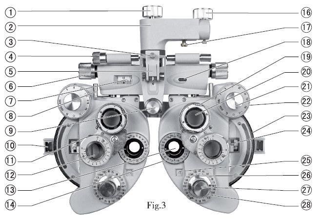
8 2.Configuration 2.1 Parts 8
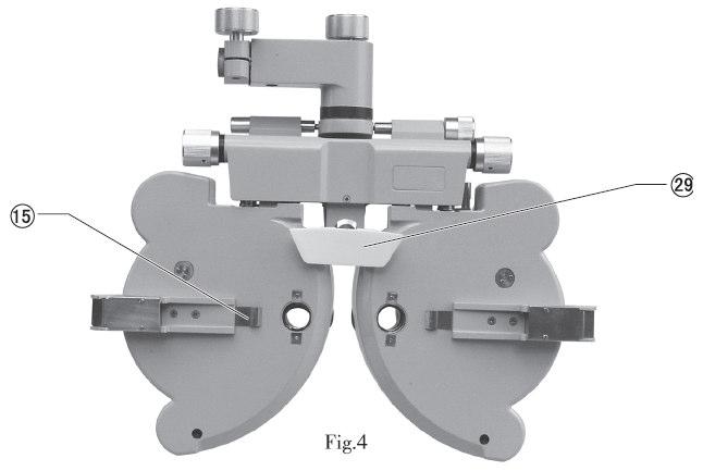
9 1. Rotation Adjustment Knob: used to adjust direction of instrument s main body 2. Mounting Handle : used to install the instrument onto eye-optometry table 3. Clamping Screw : used to fix near-point rod 4. Leveling Adjusting Knob: used to adjust level position of the instrument 5. Near Point Rod Holder: used to attach near-point testing mark rod to hanger frame 6. Pupil Distance Knob : used to adjust pupil distance 7. Pupil Distance Scale: used to display pupil distance 8. Vergence : used to adjust corner of device s left and right disks 9. Forehead Rest Knob : used to adjust patient s forehead position 10. Corneal Aligning Aperture : used to display position of patient s cornea vertex 11. Prism Rotation Knob : used to adjust prism power 12. Rotary Prism : used to test phoria or binocular balance 13. Examination Aperture for test, with various lenses set here. 14. Cylindrical Lens Axis Scale : used to indicate cylindrical lens axis angle 15. Face shield chip : fix face shield 16. Fixing Hand-wheel : used to fix instrument to ophthalmic stand 17. Tightening Screw : used to fix instrument to ophthalmic stand, and stored in accessory box 18. Spirit Level : used to indicate level direction 19. Rotation Knob : used to adjust astigmatic axis of cross cylindrical lens 20. Cross Cylindrical Lens : used to precisely check astigmatic power and axis 21. Auxiliary Lens Knob : used for various visual acuity tests 22. Strong Spherical Power Knob : used to adjust big spherical lens power, step:3.00d 23. Weak Spherical Power Dial : used to adjust small spherical lens power, step:0.25d 24. Spherical Power Scale : used to display spherical lens power 25. Cylindrical Power Scale : used to display cylindrical lens power 9

10 26. Cylindrical Lens Axis Knob : used to adjust cylindrical lens axis 27. Cylindrical Lens Knob : used to set cylindrical lens to examination aperture 28. Cylindrical Lens Axis Scale : used to display angle of cylindrical lens axis 29. Forehead Rest : Patient s forehead rests here. 30. Instruction Manual 31. Near Point Rod : Card holder is attached to position of near point measuring on this rod. 32. Near Point Card : Including near point sight mark 33. Card Holder : used to attach near point card 34. Dust Cover : Use dust cover to cover instrument when it is not in use to protect it from dust. 35. Accessories Box : used to store the standard accessories 36. Face shield :Left and right face shield's, one each, are installed on position where instrument and patient s nose contact. 37. Balloon with Brush : used to clean lens 38. Additional Lens : used to change testing range and precision 10

11 3.Assembly 3.1 Attaching Instrument to Ophthalmic Stand a/ When assembly is conducted, first insert the mounting rod extending from the ophthalmic stand to hole of mounting handle, and fix it with fixing hand-wheel. Then tighten tightening screw under mounting handle. Tightening screw is stored in standard accessories box. b/turn leveling adjusting knob 4 until air bubble is located at middle position of spirit-level bubble 18. Loosen rotation adjustment knob to turn the instrument to the required direction. *Notice Fastening screw 39 ( placed in accessories box) can be used to better fasten vision tester when it is not matching with the vision tester holding arm. 3.2 Attaching Near Point Rod, Near Point Card and Card Holder First insert card holder 33 into near point rod 31, and slide it to a proper position. Then attach near point card 32 to an open aperture of card holder 33 (Fig.8). Afterwards, attach near point rod 31 onto near point rod holder 5, and fix clamping screw 3. When near point rod 31 is not used, raise it upwards (Fig.9). 11
, turn auxiliary lens knob to O position, then turn cylindrical lens knob until \"00\" is shown on cylindrical power scale.")
.")
12 3.3 Attaching face shield Attach face shield 36 so that face shield clip 15 catches it. Then align face shield aperture with examination aperture 13 (Fig.10). 4 Operation Procedures 4.1 Spherical Lens To show the spherical power only (shortened as "S"), turn auxiliary lens knob to O position, then turn cylindrical lens knob until "00" is shown on cylindrical power scale. Then turn weak spherical power dial, value S is displayed in spherical power scale, within range from D~+16.75D, increasing or decreasing progressively in 0.25D (Fig.11). To obtain required diopter setting quickly, use strong spherical power knob, then value S increases or decreases progressively in 3.00D diopter steps (Fig.12). Note: Although several figures will appear on the scale, only three or four digit numbers have meaning. For example, if '075' is shown, it should be read as '0.75D', and if '1150' is shown, it should be read as '11.50D'. 12


13 4.2Cylinder Lens By turning cylindrical lens knob, the cylindrical power is shown on cylindrical power scale, with range from 0.00D to 6.00D, and increases or decreases progressively in 0.25D steps (Fig.13). By turning cylinder lens axis knob, the axis angle of cylinder lens is shown on cylinder lens axis scale, with range of 0~180 ; step: 5 (Fig.14) 13
. The meaning of each mark. O Open aperture OC Shelter from aperture ±.50 Cross cylinder lens, with horizontal plus +axis.")
14 4.3 Auxiliary Lens Turn auxiliary lens knob 21, the required symbol is to be set at 12 o'clock position. Then Corresponding referenced lens will appear in the examination aperture 13 (Fig.15 and Fig.16). The meaning of each mark. O Open aperture OC Shelter from aperture ±.50 Cross cylinder lens, with horizontal plus +axis. Used for presbyopia test 6U 6 diopter base up prism, used for horizontal phoria test PH A 1mm diameter pinhole is provided, used to determine reason of poor vision (due to refractive abnormity or their reasons) D spherical lens, and spherical power can be set by 0.12D Cross piece RL Red color-filter lens RMH Red Maddox rod lens, set horizontally RMV Red Maddox rod lens, set vertically P Polaroid filter, used for polarizing testing of stereoscopic vision Andbinocular balance of stereoscopic vision R Retinoscopic lens; +1.50D spherical lens (67cm) 10I 10 diopter base in prism, used for vertical phoria test GL Green color-filter lens WMH White Maddox rod lens, set horizontally WMV White Maddox rod lens, set vertically 14

. 4.")
15 To change direction of cross cylinder lens and polaroid filter, first remove the retaining ring and rear cover glass using screwdriver. Rotate the auxiliary lens knob until auxiliary lens is properly indexed and in alignment with examination aperture. By slightly turning the auxiliary lens knob in both directions, a screw and washer can be seen above and below the lens. Removing these two screws, auxiliary lens can be then removed. By reversing above procedure, reposition of lens is possible to ensure it is placed in a proper position (Fig.17). 4.4 Cross Cylindrical Lens It is used for precise determination of cylinder power and axis. Turn cross cylindrical lens to the front of examination aperture. The letter P at its front sustenance face stands for the power, and hand-wheel direction stands for axis. When red dot aligns with P it indicates minus -0.25D cylindrical lens. When white dot aligns with P it indicates plus +0.25D cylindrical lens. 15


16 4.5 Rotary Prism Turn rotary prism 12 by holding its base to set it on the examination aperture. Turn prism rotation knob 11 until the required prism power is set. What the black triangle arrow indicates is the current prism power. For example, prism power indicated in Fig.22 is 0, that in Fig.23 means base in 3 prism power, and that in Fig.24 means base up 3 prism power. 16

17 4.6 Corneal Aligning Device Turn forehead rest knob i to adjust position of forehead rest 9. After setting patient's forehead closely on forehead rest 29, look through the corneal aligning aperture 10 from around 20cm away. Look at the apex of the patient's cornea (Fig.25) after the examination aperture's pointer acme of corneal aligning aperture 10 aligns with the longer line on the scale. The longer line in the aperture means the measuring distance is 13.75mm, which is the standard spectacle wearing distance. Three shorter lines are provided by 2mm equal distance away from the longer line. If apex of the cornea of testee is positioned on second shorter line from the longer line, the lens power should be the value measured when spectacle is placed at 17.75mm away from apex of the cornea (standard value 13.75mm + correction value of second shorter line 4mm =17.75mm). If the actual spectacle wearing distance is different from the standard value (13.75mm), correction should be made according to Table 1 and Table 2. Example 1 Assume that data of S +8.00D is obtained when the apex of the cornea positioned at the second shortest line from the longest line, meaning that it is 4mm away from the standard wearing distance. When referring to the correction factor in Table 1, it is known that the applied correction factor is +0.26D for +8.00D diopter and 4mm distance. Therefore, the actual diopter of a patient who wears distance standard spectacle is (+8.00D) + (+0.26D)=8.26D. The correction value changes by 0.25 D or 0.12D. 17
18 Example 2 Assume that the apex of cornea is between the second and third shortest lines from the longest line (5mm from the standard line), the obtained data is S-11.50D. It is known when referring the correction factor in Table 2 that for D and 5mm distance, the correction value should be ( )/2= 0.62D. Thus the actual diopter of a patient who wears distance standard spectacle is (-11.50) + (+0.62)= D. Example 3 When the cornea apex is on the third shortest line from the longest one, the obtained value is D: It is known when referring to correction factor in table 2 that for D and 6mm distance, the correction value should be 1.08D. So the actual diopter of a patient who wears distance standard spectacle is (-14.00)+(1.08)= D. If more accurate measurement is required, please calculate it according to following formula. D'=D± 2 LD 1000 LD D D' L Measured power Corrected power Difference between measured distance and wearing distance(mm) 18
19 Correction Table 1 (When Correction Value of Measured Power is in Plus (+) Region ) 19
20 Correction Table 2 (When Correction Value of Measured Power is in Minus (-) Region) 20
 Near point distance from 15cm to 70cm (i.e. about 6 inches to 28 inches), and lens diopter from +8D to +1.")
21 4.7 Near Point Card If the lens is multifocal, it is required to measure lens diopter at near distance. Then near point rod, card holder and near point card can be used. Lower near point rod, keeping rod horizontal is the correct setting for measurement (Fig.27) Near point distance from 15cm to 70cm (i.e. about 6 inches to 28 inches), and lens diopter from +8D to +1.5D are provided. The value indicated at tail of card holder 33 is just the value to the card from apex of the cornea (Fig.28). Select the required sight mark on the near point card. Turn the rotating portion along the card center by the finger until the required value appears in the sight window. Then turn vergence lever 8 inward to move the instrument so that main axis of lens faces to 380mm. Now near point testing can be carried out (Fig.29). 21
22 4.8 Examination Procedures Following is an example of examination. Before examination, patient's visual acuity should be determined. Example: Testee, 35 years old, who wears spectacles. First, use lensmeter to measure the spectacles he is wearing, with following results: PD 63mm R -1.00DS/ 0.50DC 90 L -1.25DS/ 0.50DC 180 Examining results show pupil distance of Testee is 63mm; spherical power of his right eye is -1.00D, with astigmatic power of -0.50D, and axis 90 ; spherical power of his left eye is -1.25D, with astigmatic power of -0.50D, and axis 180. With these spectacles worn in examination, visual acuity of Testee's left and right eyes is all 0.7(20/30). Then use a comprehensive optometry meter to precisely measure diopter power of Testee's left and right eyes at present Installing Instrument (1)Attach the near point rod downwards to near point rod holder (Fig.9). (2)Set the spherical lens power (value S) and cylinder lens power (value C) to zero. (3)Before examination, first set pupil distance. Turn pupil distance knob, so that pupil distance of Testee is shown in pupil distance scale. (4) Move the instrument so that the instrument's side shown in Fig.4 is facing to Testee. Now place forehead of Testee on the forehead rest 29. (5)Turn leveling adjusting knob 4 while observing air bubble until the air bubble moves to middle of the water bubble. (6) Determine the distance between vertex of cornea and the instrument. (7) To measure right eye first, turn auxiliary lens knob to set O for right eye, and OC for left eye Examination Using "Fogging Method" (1)Add 3.00D to the estimated S value for right eye. Then power of his spectacle is -1.00D, namely, (-1.00)+(+3.00)= +2.00D. (2)In this condition, Testee is unable to clearly see the projected chart. Gradually add minus power. In example of Testee, reduce S value gradually by turning weak spherical power dial 23 : until it shows D. 22
. If Testee says all lines are equally bright, it means no astigmatism is existent.")
 Change S by 0.25D steps by turning weak spherical power dial 23 so that the visual acuity becomes from 1.2 to 1.5. Record the changed value of the visual acuity.")
23 (3)Project the astigmatic chart while asking Testee if he can see it. If Testee says he can see it as shown in Fig.30, turn the cylindrical lens axis knob to 90 from the darkest line he has seen (see Fig.31). If Testee says all lines are equally bright, it means no astigmatism is existent. Then procedures (3) and (4) in and procedure are not required. (4) Turn cylindrical lens knob to change C value, so every line is seen equally. When it is turned to -0.50, the chart is as shown as Fig.32. (5) Change S by 0.25D steps by turning weak spherical power dial 23 so that the visual acuity becomes from 1.2 to 1.5. Record the changed value of the visual acuity. For myopia, spectacles with least power should be selected, and for presbyopia, spectacles with largest power should be selected. To correct Testee's vision to that of 1.5, his spectacle power may be -1.75, or -2.25, and then should be selected. Now examination is almost completed, however, more precise measurement is required Precise Refining Cylinder Axis and Power (1) Set cross cylindrical lens in front of Testee 's right eye and, turning rotation 23


24 knob axially, to align it with axial direction of cylindrical lens (see Fig.33). (2) Project the cross cylinder dot chart as shown in Fig.34. Turn rotation knob 19 with finger to rotate cross cylindrical lens. Then ask Testee to compare the two images he sees before and after turning the cross cylindrical lens. Stop at the better side. For example, if what Testee sees is clearest as shown in Fig.35 of cross cylindrical lens, turn cylindrical lens axis knob to move axis of cross cylindrical lens by 5 in direction of red dot, so that position of cylindrical lens axis scale is positioned at 95. (3) Turn the lens again to make a comparison. If what Testee sees is the most clearest as shown in Fig.37, move cross cylindrical lens axially towards red dot by 5, enabling it to become 100. (4)Turn the lens again. If Testee cannot report any difference, precise examining cylinder axis is completed (with astigmatic axis of 100 ). (5) Now to conduct precise measurement of cylinder power (C), and turn letter P to original axis (see Fig.37). (6) Use cross cylinder dot chart shown in Fig.34 with same procedure as described in (2). Now ask Testee to compare the charts he sees. The result is shown as Fig.38. If Testee sees the clearest chart when red dot matches with letter P (as shown in Fig.38), it means Testee's diopter has increased by 0.25D (now Testee's diopter power is 24
 Turn the lens again to verify the finding.")
 (1) Use red and green chart to determine precise spherical lens value (see Fig.40). Ask the patient which one is seen clearest, red or green chart.")
25 0.75D). (7) Turn the lens again to make a comparison. If the chart as shown in Fig.39 is the clearest, the diopter power should be decreased by 0.25D because white dot is positioned at P. If the red dot is positioned at P, it means diopter power is increased by 0.25D, thus totally 0.5D is added. (8) Turn the lens again to verify the finding. If Testee reports that the chart in the setting of Fig.39 is clearest, the correct modified power should be between 0.25D and 0.5D. Hence the accurate power should be -0.62D Precise Refining Spherical Power (Red-Green Test) (1) Use red and green chart to determine precise spherical lens value (see Fig.40). Ask the patient which one is seen clearest, red or green chart. If the green one is seen better, it indicates myopia is increased (hyperopia decreased). The reduce spherical lens value by 0.25D (2) Ask Testee again to affirm which chart is seen clearer, the clearer red stands for decreased myopia (increased hyperopia). Testee's power is 1.62D. Generally, the 25
 Now right eye examination is completed, with lens power result as follows: Spherical power 1.50 Cylinder power 0.50 and Axis 100 R -1.50DS/-0.50DC 100 Then examine the left eye.")
26 weak spherical power dial is used to adjust myopia (and strong spherical power dial is used to adjust hyperopia). (3) Now right eye examination is completed, with lens power result as follows: Spherical power 1.50 Cylinder power 0.50 and Axis 100 R -1.50DS/-0.50DC 100 Then examine the left eye. Turn auxiliary lens knob, to set O for left eye, and OC for right eye. Then use same measuring method to measure left eye. Testee 's left eye is measured as: L -2.00DS/-0.50DC Binocular Balance Test (1) Rotary Prism Method a. Tests are performed for left and right eyes independently, in which, binocular prism shall be used for both eyes. On the whole, these tests are referred to as the binocular balance test. Set both eyes to O. Use the chart shown in Fig.34 and set prisms as 2 U (right eye), and 2D (left eye) (see Fig.41) b. Now Testee sees two images of chart, one at upper side and one at lower side. When asked which image is seen clearest, Testee replies the upper one is clearest. Then add +0.25D to spherical lens value of right eye. When the image at lower side is seen clearest, add +0.25D to spherical lens value of left eye, namely, (-2.00)+(+0.25)= -1.75D. c. Ask Testee again to affirm which one is clearest. When both become similar, it means balance test is completed. d. Remove the rotary prism. Add spherical lens power of D to both eyes. So, Testee's visual acuity should be: R -0.50DS /-0.50DC A l00 L -0.75DS /-0.50DC A l70 e. Now add minimum power of 0.25D to binocular spherical lens value. Gradually change the spherical lens value until he can see 1.2 or 1.5(20/15) visual mark clearly. 26
. Project the polarized binocular balance test chart. b. Now Testee sees two images, one at upper side and one at lower side.")
27 He desires to see 1.5 (20/15) clearly, then change spherical lens value as follows: R -1.50DS /-0.50DC A l00 L -1.75DS /-0.50DC A l70 (2) Polarizing filter method a. Turn auxiliary lens knob to P (both eyes). Project the polarized binocular balance test chart. b. Now Testee sees two images, one at upper side and one at lower side. When asked which image is seen clearest, Testee replies the upper one is clearer, and he can see upper row of the chart by his right eye, and the lower row by his left eye. If both rows can be seen with equal clarity, it means the balance is good. When both rows are not seen with equal clarity, add +0.25D spherical lens value to one eye with better clarity until both columns are seen with equal clarity. C. Turn auxiliary lens knob to O (both eyes). Add +1.00D to spherical lens value of both eyes. d. Gradually reduce spherical lens value by precision of minimum 0.25D until visual acuity for both eyes becomes 1.2 or Measuring Phoria at Far Point (1) Maddox rod and rotary prism method a. First conduct horizontal phoria measurement. Proceed according to (1) rotary prism method described in Binocular Balance Test. Turn auxiliary lens rotation knob, and set right eye to RMH ( Fig.44). Turn prism rotation knob with its setting 0 on the triangle symbol facing the left eye. Light a small fixation light at the position where the chart is projected. Now Testee's right eye can see a red vertical line (see Fig.45 a), and his left eye can see a light spot (see Fig.45 b). They are probably (a) or (b) of Fig.46. The light spot will also move when prism rotation knob 11 is turned. Then ask the patient to tell when he sees the image shown in Fig.46 b. The test result is shown in Fig.47. The prism rotation scale is shown as 2. The result of 2I (base inward) stands for 2 inclination outward. 27


28 b. Then measure vertical phoria. As shown in Fig.48, turn auxiliary lens knob 21 and set RMV for the right eye. Turn rotation prism lens 12 to set the left eye at horizontal position. Now Testee can see red horizontal line with the right eye, and the light spot with the left eye. Then using same procedure of a, ask Testee when he can see red line and light spot meet while turning prism lens rotation knob 11. When it is shown as Fig.49, Testee reports they meet, it is 0.5, below 0, indicating left eye is 0.5D, called 0.5upward heterophoria. 28

. e.")
29 (2) Polarizing Filter Method a. Turn auxiliary lens knob to P and project the polarizing chart ( Fig.50). b. Unless the patient has phoria, four lines seen to the patient will be shown as Fig.50. If the patient has phoria, these four lines will not be in alignment. c. When the vertical lines are seen disposed as shown in Fig.51-a, turn rotation prism of the left eye with 0 scale upward. Then turn prism rotation knob slowly so that the image is shown as Fig.50 (horizontal phoria). d. When horizontal lines are seen disposed as shown in Fig.51-b, adjust 0 scale to horizontal position, and then turn prism rotation knob 11 so that the image is as shown in Fig.50 (vertical phoria). e. When both vertical and horizontal lines are disposed to have phoria, as shown in Fig.51-c, adjust rotary prism 12 to make scale 0 vertical so that the vertical line is in the middle of horizontal line, as shown in Fig.51-b (horizontal phoria). Afterwards, adjust scale 0 to be horizontal. Turn prism rotation knob 11 so that horizontal lines are in the middle of vertical line, as shown in Fig.51-a (vertical phoria). 29
30 4.8.7 Arranging Results Now, examination of Testee is completed. If the results show Testee has severe phoria, the spectacles should be adjusted. If not, the prescription would be: PD 63mm R -1.5DS/-0.5DC l00 L -1.75DS/-0.5DC l Presbyopia Test This test is provided to those who are more than 45 years old. a. First, affirm distance of measurement and put it in the examination aperture. Attach near point rod and near point rod holder to the instrument, then fix them firmly using clamping screw. b. Turn auxiliary lens knob to ±.50D (both eyes). c. Use near point card as near point examination of the patient. Ask the patient how about the vertical line and horizontal line he sees. If presbyopia is seen, the horizontal line will be seen clearly, with vertical line being dull (if both lines are seen equally, presbyopia spectacles are unnecessary). d. Add 0.25 to both eyes' S simultaneously until horizontal line and vertical line are equally discernible. e. Change ±.50 of both eyes to O. Turn the near distance card to show small letters. Then ask the patient if letters are clear. A proper adjustment is required for S value. The measurement is complete. Record the results Phoria at Near Distance (1) Horizontal Phoria If the patient has no presbyopia, set the results of phoria tested at far point in aperture. If the patient has presbyopia, put the results on the near point test. Set the near point card at 40cm, and turn auxiliary lens knob to set the right eye at 6U so that letter rows are fully separated. If the patient has horizontal phoria, it will be shown as Fig.52. Turn rotary prism to the other eye, with 0 scale upward.(see Fig.54) Turn prism rotation knob so that there is no difference between the left and right eyes and, at this time, scale of the rotary prism indicates prism power(see fig.53). 30

.")
31 (2) Vertical Phoria Turn auxiliary lens knob 21 to set the left eye at 10I so that letter columns are completely separated. If the patient has vertical phoria, it will be shown as Fig.55. Then turn the rotary prism to the other eye, with scale of 0 horizontal (as shown in Fig.57). Turn prism rotation knob 11 so that there is no difference between the upper and the lower (see Fig.56). Then scale of rotary prism indicates vertical phoria power. 31
32 Other Measurements (1) Vergence (eyeball movement in different direction) Set rotary prism in front of both eyes, and place 0 setting in uppermost position. To measure adduction of eyeball at far point, turn the prism outward for both eyes simultaneously. When the chart is seen as two images in the vertical direction (the point where double vision first occurs), the reading at this time indicates adduction power. The rotary prism can be used to measure maximum 40only (about 22 ). For abduction measurement, turn the prism of both eyes inwards simultaneously. When the object is seen as a double image, record the readings. Maximum range of measurement is 40. If 10 BI is used on auxiliary lens disk, maximum test value is 50. Adduction and abduction at near point can be measured when the near point card is fixed to near point rod. The method for other measurements is identical. (2) Vertical Abduction Set rotary prism in front of both eyes, and place 0 setting in horizontal position. Use the horizontal letters in the visual acuity chart for far point (5m) test, and use near point card to conduct near point test. Turn prism rotation knob and, when horizontal letters are seen as a double image, record the reading, which is patient's vertical abduction power Transposition of Prescriptions In Comprehensive Optometry Device, myopia astigmatic method is used to carry out fogging measurement. However, when hyperopia astigmatism is required sometimes, please use correction results in following formula. XDS/YDC AZ (X+Y)DS/(-Y)DC (Z±90) S: Add the cylinder lens power to the spherical lens power C: Convert the index (+-) of cylinder lens power A: Add 90 when Z is less than 90 ; and deduct 90 when Z is larger than 90. Example 1: For +4.00DS/-1.50DC 155, changed to S:(+4.00)+(-1.50)= C:(-1.50)= A: = 65 So the result is +2.50DS/+1.50DC Example 2: For +1.5DS/+0.75DC 75 S:(+1.5)+(+0.75)= C:-(+0.75)= -0.75
33 So the result is: A: = DS/-0.75DC l65 5.Maintenance 5.1 Daily Care (1) Use dust cover to protect the instrument from dust when it is not in use. (2) For long-term storage, keep the instrument in a dry place free of dust. (3) When lens becomes dirty, use lens cleaning cloth moistened with a little absolute alcohol to wipe it. (4) Before operation. Clean Forehead Rest and nosepiece with medical cotton watted with absolute alcohol. 5.2 Checking and Servicing Procedure In normal use, no special checking or servicing is necessary. However, when it is used at extremely low temperature, the turning knobs or dials will become heavier than usual because of lubricant used inside, instead of any mechanical reason. When temperatures return to normal, all will be normal. 6 Before Requesting Service-Troubleshooting Guide If any problem occurs, first check the following items, and follow the suggested instructions. When the trouble cannot be eliminated, please contact us. (1) The required lens cannot be set at examination aperture Is knob turned to correct position? Is any other lens attached to the patient's examination aperture? (2) When vergence lever 8 is adjusted, does any action of corresponding vergence occur? 33
34 7. Transportation and Storage 7.1 Transportation Avoid sunshine, rains, heavy pressure and vibrant movement during transportation. Hold and move instruments lightly during transport and loading. No throw is allowed. During transportation, please keep the instrument well packed in original packing materials. Heavy hit may cause instrument failure. Transportation temperature: -10 C to 50 C Transportation humidity: 80% (No condensing) 7.2 Storage Store the instrument in dry, ventilated indoor place without corrosive gases. Details are below: Storage temperature: 5 C to 40 C Storage humidity: 70% (No condensing) Low dust content environment No direct sunlight 8 Optional Accessories - Cylinder Lens Three types of spare lens are optional: -2.00CYL,-0.12CYL and 00CYL. 34
35
36 Essilor Instruments USA 8600 W. Catalpa Avenue, Suite 703 Chicago, IL Phone:
AMCON LENSOMETER USER S MANUAL EQ Fax
 AMCON LENSOMETER USER S MANUAL EQ-6001 1-800-255-6161 Fax 1-800-397-0013 www.amconlabs.com CONTENTS Description and Usage... 2 Main Technical Index... 2 Principle of Operation... 2 Functions of Major Components...
REICHERT PHOROPTOR Refracting Instrument. User s Guide
 REICHERT PHOROPTOR Refracting Instrument User s Guide 2015 AMETEK, Inc. AMETEK is a registered trademark of AMETEK, Inc. Reichert, Reichert Technologies, and Phoroptor are registered trademarks of Reichert,
Ophthalmic Slit-lamp Microscope (SLM 1ER) Operation. Instruction
 Operation. Instruction") Ophthalmic Slit-lamp Microscope (SLM 1ER) Operation Instruction Content 1. Introduction... 2 1.1 Characteristics:... 2 1.2 Technical Parameters... 2 1.3 Notes:... 3 1.4 Caution:... 3 2. Installation...
Ophthalmic Slit-lamp Microscope (SLM 1ER) Operation Instruction Content 1. Introduction... 2 1.1 Characteristics:... 2 1.2 Technical Parameters... 2 1.3 Notes:... 3 1.4 Caution:... 3 2. Installation...
VARILUX FITTING GUIDE GUIDELINES FOR SUCCESSFULLY FITTING VARILUX LENSES
 VARILUX FITTING GUIDE GUIDELINES FOR SUCCESSFULLY FITTING VARILUX LENSES WELCOME We are pleased to present this guide which outlines the essential steps for successfully fitting progressive lenses to your
User Manual. Digital Compound Binocular LED Microscope. MicroscopeNet.com
 User Manual Digital Compound Binocular LED Microscope Model MD82ES10 MicroscopeNet.com Table of Contents i. Caution... 1 ii. Care and Maintenance... 2 1. Components Illustration... 3 2. Installation...
Learn Connect Succeed. JCAHPO Regional Meetings 2017
 Learn Connect Succeed JCAHPO Regional Meetings 2017 Refractometry JCAHPO Continuing Education Program Phoenix and Scottsdale, AZ Craig Simms BSc, COMT, CDOS, ROUB Director of Education, IJCAHPO Program
Compound Microscopes Instruction Manual
 Compound Microscopes Instruction Manual Thank you for purchasing an Omano microscope. We hope you enjoy it! It has been checked for quality before shipping, but please take time to ensure that it has not
Intelligent Refractor RT-5100
 Intelligent Refractor RT-5100 RT-5100 Reliability and Technology Assured 2 technology Reliable 3 Usability page page Experience the excellence with the RT-5100. Do you know what RT stands for? Originally
Intelligent Refractor RT-5100
 Intelligent Refractor RT-5100 RT-5100 Reliability and Technology Assured 2 technology Reliable 3 usability page page Experience the excellence with the RT-5100. Do you know what RT stands for? Originally
User Manual. Trinocular Metallurgical Microscope. MicroscopeNet.com
 User Manual Trinocular Metallurgical Microscope Model M83MPTR MicroscopeNet.com Table of Contents i. Caution.. 1 ii. Care and Maintenance... 2 1. Components Illustration..... 3 2. Installation...4 3. Operation
STEINDORFF NYMC Polarizing Microscope
 NYMC38000 Polarizing Microscope In order to exert performance of this microscope and to ensure the safety, please read the operating instruction carefully before use. 1 I. APPLICATION: NYMC38000 series
Components of the Microscope
 Swift M3 Microscope The Swift M3 is a versatile microscope designed for both microscopic (high magnification, small field of view) and macroscopic (low magnification, large field of view) applications.
User instructions Transmitted light laboratory microscope
 KERN & Sohn GmbH Ziegelei 1 D-72336 Balingen E-Mail: info@kern-sohn.com Tel: +49-[0]7433-9933-0 Fax: +49-[0]7433-9933-149 Internet: www.kern-sohn.com User instructions Transmitted light laboratory microscope
Tabletop Refraction System TS-310
 Tabletop Refraction System TS-310 Design your space The TS-310 is a tabletop subjective refraction system that integrates chart and refractor into a single unit. NIDEK's recognized quality examination
Zoom Stereo Microscope NYMCS-360 Instruction Manual
 Zoom Stereo Microscope NYMCS-60 Instruction Manual This manual is written for stereo microscope NYMCS-60. To ensure the safety, obtain optimum performance and to familiarize yourself fully with the use
Keratometry: Vertical Axis. Axis
 Keratometry: Step 1: FOCUS THE EYEPIECE Lower occluder, focus the keratometer light source on the occluder. Turn the eyepiece counter-clockwise until blurry, then rotate clockwise JUST until clear, no
OMM300. Inverted Metallurgical Microscope
 OMM300 Inverted Metallurgical Microscope Instruction Manual Please read the instructions carefully before operating CONTENTS Safety 2 Parts List 2 Features 3 Assembly 5 Operation 7 Maintenance 9 Specifications
Maintenance Information
 16601023 Edition 2 January 2014 Air Impact Wrench 2705P1 Maintenance Information Save These Instructions Product Safety Information WARNING Failure to observe the following warnings, and to avoid these
User instructions Compound laboratory microscope
 KERN & Sohn GmbH Ziegelei 1 D-72336 Balingen E-mail: info@kern-sohn.com User instructions Compound laboratory microscope Tel: +49-[0]7433-9933-0 Fax: +49-[0]7433-9933-149 Internet: www.kern-sohn.com KERN
Therefore, all descriptions and illustrations in this instruction manual, including all specifications are subject to change without notice.
 We are constantly endeavouring to improve our instruments and to adapt them to the requirements of modern research techniques and testing methods. This involves modification to the mechanical structure
ML7520 ML7530 DIOPTER ADJUSTMENT RING BINOCULAR BODY, INCLINED 30. (a) Field Iris Control Lever. (c) Filter Slots EYEPIECES, KHW10X
 Field Iris Control Lever. (c) Filter Slots EYEPIECES, KHW10X") JAPAN DIOPTER ADJUSTMENT RING BINOCULAR BODY, INCLINED 30 (a) Field Iris Control Lever (c) Filter Slots EYEPIECES, KHW10X ANALYZER CONTROL LEVER (b) Aperture Iris Control Lever LIGHT SOURCE HOUSING VERTICAL
JAPAN DIOPTER ADJUSTMENT RING BINOCULAR BODY, INCLINED 30 (a) Field Iris Control Lever (c) Filter Slots EYEPIECES, KHW10X ANALYZER CONTROL LEVER (b) Aperture Iris Control Lever LIGHT SOURCE HOUSING VERTICAL
Biological Microscope Manual
 Version No.: V1.2 Series Biological Microscope Manual This manual expatiates the using method, troubleshooting and maintenance about MT-50 series biological microscope. Please study this manual thoroughly
User instructions Transmitted light phase contrast microscope
 KERN & Sohn GmbH Ziegelei 1 D-72336 Balingen E-Mail: info@kern-sohn.com Tel: +49-[0]7433-9933-0 Fax: +49-[0]7433-9933-149 Internet: www.kern-sohn.com User instructions Transmitted light phase contrast
Notification. Precautions
 Notification Dear Users, Thank you for your purchase of LM 200 Lensmeter. Please take time to read our user s manual carefully before use. This guarantees you to make full use of this unit and prolongs
User instructions Compound laboratory microscope
 KERN & Sohn GmbH Ziegelei 1 D-72336 Balingen E-mail: info@kern-sohn.com User instructions Compound laboratory microscope Tel: +49-[0]7433-9933-0 Fax: +49-[0]7433-9933-149 Internet: www.kern-sohn.com KERN
TABLE OF CONTENTS. Safety notes i. Care and Maintenance. ii. 1. Components Illustration Installation of Components.. 4
 TABLE OF CONTENTS Safety notes i Care and Maintenance. ii 1. Components Illustration... 1 2. Installation of Components.. 4 2.1 Installation Diagram... 4 2.2 Installation Procedures 5 3. Operation...11
User Manual. Trinocular Infinity Compound LED Microscope. MicroscopeNet.com
 User Manual Trinocular Infinity Compound LED Microscope Model M8333Z series MicroscopeNet.com Table of Contents i. Caution... 1 ii. Care and Maintenance... 2 1. Components Illustration... 3 2. Installation...
Human Eye Model OS-8477A
 Instruction Manual 02-3032A Human Eye Model OS-8477A 800-772-8700 www.pasco.com Table of Contents Contents Quick Start............................................................ Introduction...........................................................
PART 3: LENS FORM AND ANALYSIS PRACTICE TEST - KEY
 PART 3: LENS FORM AND ANALYSIS PRACTICE TEST - KEY d 1. c 2. To determine the power of a thin lens in air, it is necessary to consider: a. front curve and index of refraction b. back curve and index of
Manual for BMS E1 eplan series, compound microscope
 Manual for BMS E1 eplan series, compound microscope The compound microscope allows it to study, at cell level, structures of textures of botanical and zoological nature. (e.g. slides of roots, leaves and
User instructions Metallurgical inverted microscope
 KERN & Sohn GmbH Ziegelei 1 D-72336 Balingen E-mail: info@kern-sohn.com Tel: +49-[0]7433-9933-0 Fax: +49-[0]7433-9933-149 Internet: www.kern-sohn.com User instructions Metallurgical inverted microscope
OPERATING INSTRUCTIONS
 OPERATING INSTRUCTIONS Rotary Microtome CUT 4062 / CUT 5062 / CUT 6062 CUT 6062 illustrated above INS1000GB 2012-01-06 Instructions CUT4062 / CUT 5062 / CUT 6062 2 CONTENTS 1. INTENDED USE... 4 2. SYMBOLS...
PART 3: LENS FORM AND ANALYSIS PRACTICE TEST
 PART 3: LENS FORM AND ANALYSIS PRACTICE TEST 1. 2. To determine the power of a thin lens in air, it is necessary to consider: a. front curve and index of refraction b. back curve and index of refraction
Distribution of Refractive Error. 20 year old males. Distribution of Aberrations
 Distribution of Refractive Error 20 year old males Distribution of Aberrations Aberrations and Accommodation Unaccommodated Aberations Change with Accommodation Spherical Aberration goes to zero for 2-3
SWIFT SERIES M2252DGL MICROSCOPE
 SWIFT SERIES M2252DGL MICROSCOPE The M2252DGL Series is ideal for elementary to high school classrooms. Built to withstand student use, this series has locked-on eyepieces, objectives, illuminator housing
Quick Set Dovetail Jig
 Quick Set Dovetail Jig FOR HELP OR ADVISE ON THIS PRODUCT PLEASE CALL OUR CUSTOMER SERVICE HELP LINE : 01509 500359 THE MANUFACTURER RESERVES THE RIGHT TO ALTER THE DESIGN OR SPECIFICATION TO THIS PRODUCT
D25122(K) D25123(K) D25124(K) D25213(K)
 D25123(K) D25124(K) D25213(K)") D25122(K) D25123(K) D25124(K) D25213(K) English 6 Copyright DEWALT 2 3 1 5 4 9 7 6 11 10 D25213 5 4 3 9 7 6 11 10 1 2 D25123 8 4 A D25122 D25124 3 5 4 6 B1 5 4 7 12 B2 C 10 9 11 D 4 E 3 3 F1 F2 6 8 13
D25122(K) D25123(K) D25124(K) D25213(K) English 6 Copyright DEWALT 2 3 1 5 4 9 7 6 11 10 D25213 5 4 3 9 7 6 11 10 1 2 D25123 8 4 A D25122 D25124 3 5 4 6 B1 5 4 7 12 B2 C 10 9 11 D 4 E 3 3 F1 F2 6 8 13
MANUAL EXC-350 MICROSCOPE SERIES
 MANUAL EXC-50 MICROSCOPE SERIES 7 Mall Drive, Commack, NY 75 6-864-000 (P) 6-54-8900 (F) www.accu-scope.com info@accu-scope.com CONTENTS SAFETY NOTES... CARE AND MAINTENANCE... INTRODUCTION... 4 UNPACKING
REPAIR INSTRUCTIONS. Cat. No Cat. No MILWAUKEE ELECTRIC TOOL CORPORATION. SDS Max Demolition Hammer. SDS Max Rotary Hammer
 Cat. No. 9-0 SDS Max Demolition Hammer Cat. No. -0 SDS Max Rotary Hammer MILWAUKEE ELECTRIC TOOL CORPORATION W. LISBON ROAD BROOKFIELD, WISCONSIN 00-0 8-9-0 d 000 8-9-0 d Special Tools Require Forcing
JUMBO STENCIL CUTTING MACHINE PARTS LIST AND OPERATING MANUAL
 JUMBO STENCIL CUTTING MACHINE PARTS LIST AND OPERATING MANUAL Marion, IL USA STK. NO. 5800-152, REV A Warning: This machine contains pinch points which can injure personnel when not used properly. This
User instructions Metallurgical microscope
 KERN & Sohn GmbH Ziegelei 1 D-72336 Balingen E-Mail: info@kern-sohn.com User instructions Metallurgical microscope Tel: +49-[0]7433-9933-0 Fax: +49-[0]7433-9933-149 Internet: www.kern-sohn.com KERN OKM-1
User instructions Transmitted light laboratory microscope (digital)
") KERN & Sohn GmbH Ziegelei 1 D-72336 Balingen E-Mail: info@kern-sohn.com Tel: +49-[0]7433-9933-0 Fax: +49-[0]7433-9933-149 Internet: www.kern-sohn.com User instructions Transmitted light laboratory microscope
KERN & Sohn GmbH Ziegelei 1 D-72336 Balingen E-Mail: info@kern-sohn.com Tel: +49-[0]7433-9933-0 Fax: +49-[0]7433-9933-149 Internet: www.kern-sohn.com User instructions Transmitted light laboratory microscope
Training Eye Instructions
 Training Eye Instructions Using the Direct Ophthalmoscope with the Model Eye The Model Eye uses a single plastic lens in place of the cornea and crystalline lens of the real eye (Fig. 20). The lens is
CONTENTS PRECAUTIONS BEFORE STARTING OPERATION PREPARATION FOR OPERATION CAUTIONS ON USE OPERATION
 CONTENTS PRECAUTIONS BEFORE STARTING OPERATION ------------------------------------- 1 PREPARATION FOR OPERATION 1. Adjustment of needle bar stop position ---------------------------------------------------------
3 IN 1 HEAVY DUTY TILE CUTTER. Model Visit our website at:
 3 IN 1 HEAVY DUTY TILE CUTTER Model 41711 ASSEMBLY Operating Instructions Visit our website at: http://www.harborfreight.com Read this material before using this product. Failure to do so can result in
O P E R A T I N G I N S T R U C T I O N S
 E N L A R G E R MODEL 3C - 2B O P E R A T I N G I N S T R U C T I O N S Manufactured in India by (Rajkot, Gujarat) Description: Modern Model 3C-2B is a precision enlarger designed to take negatives up
XI. Rotary Attachment Setups
 XI. Rotary Attachment Setups 1) Turn off the laser. 2) Put the rotary attachment onto the engraving table. Ensure the two screw holes on right side of rotary attachment match the two corresponding holes
Operation Instructions
 High Speed Coin Counter With Automatic Hopper Operation Instructions Content 1. Introduction. 3 2. Whole Machine Figure. 3 3. Technical Specifications 4 4. Key Panel..4 5. Precautions 5 6. Operation Procedures..6
S E L E C T I O N. Arm Curl. User manual
 S E L E C T I O N T H E S T R E N G T H E V O L U T I O N User manual The identification plate of the and manufacturer, affixed behind the seat, gives the following details: A Name and address of the manufacturer
INTRODUCTION TO LENSOMETRY
 INTRODUCTION TO LENSOMETRY Susan Brummett, COMT Little Rock, Arkansas January 2007 Terminology 1 Lensmeter instrument designed to measure the prescription of an optical lens. Also defined as an instrument
Marco TRS Total Refraction System
 Marco TRS-5100 Total Refraction System TRS-5100: Total Refraction System The TRS has a forehead position detector (blue LED) for reliable vertex measurements. Wide Visual Field (40 ) apertures provide
Versatile Functionality RT-5100 SMART REFRACTOR
 Versatile Functionality SMART REFRACTOR Smart Refractor Patient-Friendly Smart, Ergonomic Design for Patient Comfort Wide Visual Field (40º) R/L-Independent PD Adjustment for Improved Precision Right and
Kontax Stirling Engines KS90R instructions
 Kontax Stirling Engines KS90R instructions This document covers the following: Tools required Parts list Assembly instructions Operating instructions Maintenance Contact details: www.stirlingengine.co.uk
Kontax Stirling Engines KS90T instructions
 Kontax Stirling Engines KS90T instructions This document covers the following: Tools required Parts list Assembly instructions Operating instructions Maintenance Contact details: www.stirlingengine.co.uk
SAFETY AND OPERATING MANUAL. Portable versatile workstation
 SAFETY AND OPERATING MANUAL Original instructions Portable versatile workstation wu063 1 2 3 4 5 6 7 8 9 Safety instructions Warning! When using this product basic safety precautions should always be followed.
User instructions Polarisation microscope
 KERN & Sohn GmbH Ziegelei 1 D-72336 Balingen E-mail: info@kern-sohn.com User instructions Polarisation microscope Tel: +49-[0]7433-9933-0 Fax: +49-[0]7433-9933-149 Internet: www.kern-sohn.com KERN OPM-1,
FITTING GUIDE. Duette Hybrid Contact Lenses Duette Progressive Hybrid Contact Lenses - Center Distance - Center Near
 FITTING GUIDE Duette Hybrid Contact Lenses Duette Progressive Hybrid Contact Lenses - Center Distance - Center Near P R O G R E S S I V E The unique advanced-technology Duette hybrid contact lenses are
Trial Lens Sets. Full Set includes:
 Trial Lens Sets Trial Lens Set in Traditional Chrome Rims This trial lens set provides the full complement of 268 lenses packaged in an attractive lockable briefcase. Space is provided for your choice
Sabre Series 2 Inspired Design Precision Engineering
 Sabre Series 2 Inspired Design Precision Engineering USER INSTRUCTIONS Thank you for choosing the Keencut Sabre Series 2. Every effort has been made to bring you a precision engineered product with the
Solid Sample Holder Accessory
 Installation category I Pollution degree 2 Equipment class III Introduction The Solid Sample Holder for the Agilent Cary Eclipse is an accessory that enables you to perform fluorescence measurements on
12mm (Max) 6mm (Max) 82mm (Max) 12mm (Max) 6mm (Max)
 6mm (Max) 82mm (Max) 12mm (Max) 6mm (Max)") 1 1 2 2 3 3 82mm (Max) 12mm (Max) 12mm (Max) 6mm (Max) 4 4 5 6 8 6mm (Max) 0.5 0mm 1 5 6 7 7 8 9 9 A = B 10 11 12 D B 1 13 14 15 0 C A D E 16 17 18 F G D B N H J G I K 19 A 20 G L 21 C K 1mm L M 1mm 22
1 1 2 2 3 3 82mm (Max) 12mm (Max) 12mm (Max) 6mm (Max) 4 4 5 6 8 6mm (Max) 0.5 0mm 1 5 6 7 7 8 9 9 A = B 10 11 12 D B 1 13 14 15 0 C A D E 16 17 18 F G D B N H J G I K 19 A 20 G L 21 C K 1mm L M 1mm 22
VARIABLE SPEED WOOD LATHE
 MODEL MC1100B VARIABLE SPEED WOOD LATHE INSTRUCTION MANUAL Please read and fully understand the instructions in this manual before operation. Keep this manual safe for future reference. Version: 2015.02.02
USER MANUAL. Latitude Spotting Scopes SM11033, SM11033T SM11034, SM11034T
 USER MANUAL Latitude Spotting Scopes SM11033, SM11033T SM11034, SM11034T ABOUT SIGHTMARK Sightmark offers a wide range of products that include red dot scopes, reflex sights, rangefinders, riflescopes,
Artisan Technology Group is your source for quality new and certified-used/pre-owned equipment
 Artisan Technology Group is your source for quality new and certified-used/pre-owned equipment FAST SHIPPING AND DELIVERY TENS OF THOUSANDS OF IN-STOCK ITEMS EQUIPMENT DEMOS HUNDREDS OF MANUFACTURERS SUPPORTED
OPERATOR MANUAL AUTO LENSMETER TL-100
 OPERATOR MANUAL AUTO LENSMETER TL-100 HOLD Read this Operator Manual carefully before using this instrument in order to operate it properly and safely. Do not use procedures other than those specified
Kontax Stirling Engines KS90 instructions
 Kontax Stirling Engines KS90 instructions This document covers the following: Tools required Parts list Assembly instructions Operating instructions Maintenance Contact details: www.stirlingengine.co.uk
 GENERAL OPERATIONAL PRECAUTIONS WARNING! When using electric tools, basic safety precautions should always be followed to reduce the risk of fire, electric shock and personal injury, including the following.
Instruction Manual for Recipro Handpiece Model: Z-6X #
 Instruction Manual for Recipro Handpiece Model: Z-6X #510-2160 Introduction Gesswein Power Hand 2X Recipro handpieces are manufactured to the highest standards available to provide many years of trouble-free
S E L E C T I O N. Upper Back. User manual
 and S E L E C T I O N T H E S T R E N G T H E V O L U T I O N User manual and and The identification plate of the and manufacturer, affixed to the frame on the side opposite the padded rest, gives the
ISH-R150 MANUAL ROCKWELL HARDNESS TESTER OPERATION MANUAL
 MN-ISH-R15-E www.insize.com ISH-R15 MANUAL ROCKWELL HARDNESS TESTER OPERATION MANUAL Attention Description This Instruction Manual shall be carefully read through in prior to use of the apparatus to clearly
Sable Frame Series. Fixed Frame Projection Screen. Featuring CineGrey 3D Ambient Light Rejecting Material. User s Guide
 Sable Frame Series Fixed Frame Projection Screen Featuring CineGrey 3D Ambient Light Rejecting Material User s Guide Congratulations on your new Sable Frame purchase! The screen material included is our
HOW WE LL PROCEED. I ll put up a statement. You guess the answer Yes no True-false. You Focus the Lensometer Using the Target Circles.
 HOW WE LL PROCEED I ll put up a statement Lensometers Don t Read Power Ed De Gennaro Midlothian, Virginia OPTICAL MYTHS, HALF TRUTHS AND FALSEHOODS You guess the answer Yes no True-false True! HOW A LENSOMETER
Trouble Shooting Guide for Ortho-K lenses
 Trouble Shooting Guide for Ortho-K lenses The basic design of the third generation e Lens for Orthokeratology 1. Optic Zone (Base curve, Compression zone, BC) width 5.6 to 6.4mm 2. Fitting curve (second
Lenses- Worksheet. (Use a ray box to answer questions 3 to 7)
") Lenses- Worksheet 1. Look at the lenses in front of you and try to distinguish the different types of lenses? Describe each type and record its characteristics. 2. Using the lenses in front of you, look
Lenses- Worksheet 1. Look at the lenses in front of you and try to distinguish the different types of lenses? Describe each type and record its characteristics. 2. Using the lenses in front of you, look
Phoroptor VRx Digital Refraction System. User s Guide
 Phoroptor VRx Digital Refraction System User s Guide 2017 AMETEK, Inc. Reichert, Reichert Technologies, Phoroptor, and ClearChart are registered trademarks of Reichert, Inc. AMETEK is a registered trademark
Cut-True 16M Manual Paper Cutter
 Cut-True 16M Manual Paper Cutter 2/2013 OPERATOR MANUAL FIRST EDITION TABLE OF CONTENTS TOPIC PAGE Specifications 1 Safety Guidelines 1 Assembly 2 Overview 3 Description of Equipment Parts 3-4 Operation
SERVICE MANUAL FOR HOMELOCK M1034D 2034D 1134DW 1134D
 SERVICE MANUAL FOR HOMELOCK M1034D 2034D 1134DW 1134D 11.2000 2.2012 I HOW TO USE THIS MANUAL... 1 II HOW TO ADJUST... 2 1. Height of needle bar... 2 2. Position of the lowerlooper... 3 3. Timing of the
Metrology Prof. Dr Kanakuppi Sadashivappa Bapuji Institute of Engineering and Technology Davangere. Lecture 24 Measurement of Screw Thread Element
 Metrology Prof. Dr Kanakuppi Sadashivappa Bapuji Institute of Engineering and Technology Davangere Lecture 24 Measurement of Screw Thread Element I welcome you all for the module 6 lecture 2, in this lecture
Preface. General Requirements for Safety. Precautions
 Preface Thank you for purchasing our ESL-700 portable slit-lamp microscope. Please read this manual carefully for the sake of your best use. General Requirements for Safety Please read carefully about
SERVICE MANUAL PARTS LIST MODEL: NH40
 SERVICE MANUAL & PARTS LIST MODEL: NH40 CONTENTS What to do when... 1-3 SERVICE ACCESS Face Cover... 4 Bed Cover... 5 Free-arm Cover... 6 Front Cover... 7 Rear Cover... 8 MECHANICAL ADJUSTMENT Presser
2Win Binocular Mobile Refractometer and Vision Analyzer
 2Win Binocular Mobile Refractometer and Vision Analyzer The smartest way to detect refractive errors and vision problems Adaptica was founded in 2009 as a spin-off of the University of Padova, Italy specialising
TEKSCOPE MICROSCOPE. Models N2 Series USER S MANUAL
 TEKSCOPE MICROSCOPE Models N2 Series USER S MANUAL Contents Before use 1 1.Nomenclature. 2 2.Operation 4 2-1 Angle of observation.. 4 2-2 Set the specimen slide.. 4 2-3 Set illumination 4 2-4 Adjust focus
Topic 4: Lenses and Vision. Lens a curved transparent material through which light passes (transmit) Ex) glass, plastic
 Ex) glass, plastic") Topic 4: Lenses and Vision Lens a curved transparent material through which light passes (transmit) Ex) glass, plastic Double Concave Lenses Are thinner and flatter in the middle than around the edges.
Topic 4: Lenses and Vision Lens a curved transparent material through which light passes (transmit) Ex) glass, plastic Double Concave Lenses Are thinner and flatter in the middle than around the edges.
SAFETY AND OPERATING MANUAL
 SAFETY AND OPERATING MANUAL BladeRunner X2 WX572 9 10 8 11 5 7 12 6 20 1 2 4 3 14 13 15 A2 A1 17 18 B2 B1 1 2 1 2 19 B3 3 4 2 C 1 D1 D1 C 2 1 E1 D2 1 2 E2 1 2 F G1 G1 F OFF ON G2 G3 H1 H2 I1 I2 I1 I2 J
COMPLEX GRINDER OF MILL& DRILL
 COMPLEX GRINDER OF MILL& DRILL MODEL: MR-F6 OPERATING INSTRUCTION PLEASE REMEMBER 1. When using electric tools, machines or equipment, basic safety precautions should always be followed to reduce the risk
USER MANUAL & PARTS LIST MODEL 40B S/N:
 NUMBERALL STAMP & TOOL CO., INC. USER MANUAL & PARTS LIST MODEL 40B S/N: P.O. BOX 187, 1 HIGH ST. SANGERVILLE, ME 04479 www.numberall.com office@numberall.com TEL: 207-876-3541 FAX: 207-876-3566 MODEL
Dispensing 1. Prepared by Hatem S.H. Barhoom MHSC (clinical optometry) UKM Malaysia
 UKM Malaysia") Dispensing 1 Prepared by Hatem S.H. Barhoom MHSC (clinical optometry) UKM Malaysia Syllabus Ophthalmic lenses Uses of spectacle lenses Measurement of lenses power Neutralisation Lensmeter Uses Laying out
Dispensing 1 Prepared by Hatem S.H. Barhoom MHSC (clinical optometry) UKM Malaysia Syllabus Ophthalmic lenses Uses of spectacle lenses Measurement of lenses power Neutralisation Lensmeter Uses Laying out
Cleaning the cutter blade
 Cleaning the cutter blade < Daily maintenance > In order to use this printer in good condition, please perform the daily maintenance. Note the following when performing the maintenance. Do not lubricate
Kontax Stirling Engines KS90S instructions
 Kontax Stirling Engines KS90S instructions This document covers the following: Tools required Parts list Assembly instructions Operating instructions Maintenance Contact details: www.stirlingengine.co.uk
SIMPLEX ELITE MAT CUTTER
 INSTRUCTION MANUAL MODEL 750-1 / 760-1 SIMPLEX ELITE MAT CUTTER INSTRUCTIONS AND OPERATION MANUAL 40 in (101 cm) mat cutting system with bevel & straight cutters, production stops, 27 in (68 cm) squaring
High Speed Air Turbine Handpiece
 OPERATION MANUAL High Speed Air Turbine Handpiece Please read this Operation Manual carefully before use and file for future reference. Handpiece should not be used with friction grip burs exceeding 18.5
Motorized M3 AX7200 Rotary-Style Gasket Cutter Operating Instructions
 Motorized M3 AX7200 Rotary-Style Gasket Cutter Operating Instructions INTRODUCTION Congratulations! You are the owner of the finest rotary-style gasket cutter in the world. Originally developed and patented
3/31/2016. Presented by: Bob Alexander, ABOM/NCLE-AC Lens Consultant Vision Ease. Everywhere and Sportwrap; Understanding Digital Technology
 Everywhere and Sportwrap; Understanding Digital Technology Presented by: Bob Alexander, ABOM/NCLE-AC Lens Consultant Vision Ease Digital - Design and Surfacing VE Digital Designs Optimization Compensation
INTRODUCTION. SO-2200LED Binocular Indirect Ophthalmoscope
 INTRODUCTION Please read the following information carefully before installing and using the Scan Optics SO-2200LED binocular indirect ophthalmoscope. Scan Optics is responsible for the safety, reliability
Chapter 4 Assessment of Study Measures
 Chapter 4: Assessment of Study Measures...2 4.1 Overview...2 4.1.1 Overview of Eligibility and Masked Examination Procedures...2 4.1.2 Equipment Needed for Masked Examination Procedures...3 4.2 Primary
LO - Lab #06 - The Amazing Human Eye
 LO - Lab #06 - In this lab you will examine and model one of the most amazing optical systems you will ever encounter: the human eye. You might find it helpful to review the anatomy and function of the
Refraction Training Manual
 INTERNATIONAL CENTRE FOR EYE HEALTH Refraction Training Manual 2006 Mr S. Mayer & International Centre for Eye Health Contents Page 1. Introduction 2. Basic Optics 3. Vision and Visual Acuity 4. Refractive
8-Ton Manual Splitter OWNER S MANUAL
 8-Ton Manual Splitter OWNER S MANUAL WARNING: Read carefully and understand all ASSEMBLY AND OPERATION INSTRUCTIONS before operating. Failure to follow the safety rules and other basic safety precautions
assembly instructions
 door opens outwards door opens inwards front cubicle door opens outwards or inwards with side panel seite 1 ensure that the supplied parts are complete by checking the packing list. make sure that tools
EasyStitch. Instruction and guarantee manual 1 YEAR GUARANTEE
 EasyStitch Instruction and guarantee manual 1 YEAR GUARANTEE CONTENTS: 1. Machine Parts 2. Accessories 3. Safety Instructions 4. Battery Installation 5. Threading 6. Fitting fabric and sewing 7. Adjusting