User instructions Polarisation microscope
|
|
|
- Ginger Bailey
- 5 years ago
- Views:
Transcription

![+49-[0]7433-9933-149 Internet: www.kern-sohn.](/docs-images/87/96665221/images/1-1.jpg "com KERN OPM-1, OPN-1, OPO-1 OPM 181 OPN 182, OPN 184 OPO 183, OPO 185")
1 KERN & Sohn GmbH Ziegelei 1 D Balingen info@kern-sohn.com User instructions Polarisation microscope Tel: +49-[0] Fax: +49-[0] Internet: KERN OPM-1, OPN-1, OPO-1 OPM 181 OPN 182, OPN 184 OPO 183, OPO 185 Version /2016 OPM-1_OPN-1_OPO-1-BA-e-1510
2
3 GB KERN OPM-1, OPN-1, OPO-1 Version /2016 User instructions Polarisation microscope Table of contents 1 Before use General notes Notes on the electrical system Storage Maintenance and cleaning Nomenclature Technical data / Features Assembly Analyser unit (+ reflected light unit) Microscope head Objectives Eyepieces Condenser (Swing out) / Transmitting light polariser Operation Getting started (Pre-) focussing Adjusting the interpupillary distance Dioptre adjustment Centre-adjusting the stage Adjusting the magnification Using eye cups Adjusting the analyser unit Adjusting the Koehler illumination for transmitted light Adjusting the illumination for incident light Changing the bulb Transmitted light Reflected light Changing the fuse Transmitted light Reflected light Using optional accessories Camera connection (only for trinocular version) Trouble shooting Service Disposal Further information OPM-1_OPN-1_OPO-1-BA-e
4 1 Before use 1.1 General notes You must open the packaging carefully, to make sure that none of the accessories in the packaging fall on the floor and get broken. In general, microscopes should always be handled carefully because they are sensitive precision instruments. When using or transporting the microscope it is particularly important to avoid abrupt movements, as this may damage the optical components. You should also avoid getting dirt or finger prints on the lens surface, because in most cases this will reduce image clarity. To maintain the performance of the microscope, it must never be disassembled. So components such as lenses and other optical elements should be left as they were before use. Also the electrical parts on the rear and base of the device must not be tampered with, as in this area there is an additional risk of triggering an electric shock. 1.2 Notes on the electrical system Before connecting to a mains power supply, you must make sure that you are using the correct input voltage. The information to select the correct mains cable is located on the device, on the rear of the product directly above the connection socket. You must comply with this information. If you do not comply with these specifications, then fires or other damage to the device could occur. The main switch must also be switched off before the mains cable is connected. In this way you will avoid triggering an electric shock. If you are using an extension cable, then the mains cable you use must be earthed. If the original fuse should blow, it must only be replaced by an appropriate fuse. Suitable replacement fuses are included with the delivery. When carrying out any procedures whereby you come into contact with the electrical system of the device, such as, for example, changing the bulb or fuse, only carry out these procedures when the power is disconnected. 3 OPM-1_OPN-1_OPO-1-BA-e-1510
5 Under no circumstances should you touch the integrated halogen bulbs either during operation or directly after use. These bulbs produce significant heat and therefore there is a risk that the user could be severely burnt. So before handling the bulbs, you must check that they have cooled down. The microscope housing, on the other hand, is constructed so that no significant heat radiation emanates from the device and that there is absolutely no risk of the user burning themselves from the housing outer surfaces. 1.3 Storage You should ensure that the device is not exposed to direct sunlight, temperatures which are too high or too low, vibrations, dust or a high level of humidity. The ideal temperature range is between 0 and 40 C and a relative humidity of 85% should not be exceeded. The device should always be located on a rigid, smooth, horizontal surface. When the microscope is not being used, you should cover it with the enclosed dust protective cover. When doing this, the power supply is stopped by switching off at the main switch and unplugging the mains cable. If the eyepieces are being stored separately, the protective caps must be fitted to the tube connectors. In most cases, if dust and dirt gets inside the optical unit of a microscope this can cause irreversible errors or damage. The best way to store accessories which consist of optical elements, such as, for example, eyepieces and objectives, is in a dry box with desiccant. OPM-1_OPN-1_OPO-1-BA-e
6 1.4 Maintenance and cleaning In any event, the device must be kept clean and dusted regularly. If any moisture should be occur, before you wipe down the device you must ensure that the mains power is switched off. When glass components become dirty, the best way to clean them is to wipe them gently with a lint-free cloth. To wipe oil stains or finger prints off the lens surface, moisten the lint free cloth with a mixture of ether and alcohol (70 / 30 ratio) and use this to clean the lens. You must be careful when handling ether and alcohol, as these are highly flammable substances. You must therefore keep it away from naked flames and electrical devices which can be switched on and off, and only use it in well-ventilated rooms. However organic solutions of this type should not be used to clean other components of the device. This could lead to damage to the paint finish. To do this, it is sufficient to use a neutral cleaning product. You could also use the following cleaning products to clean the optical components: Special cleaner for optical lenses Special optical cleaning cloths Bellows Brush When handled correctly and checked regularly, the microscope should give many years of efficient service. Should repairs still be necessary, please contact your KERN dealer or our Technical Department. 5 OPM-1_OPN-1_OPO-1-BA-e-1510
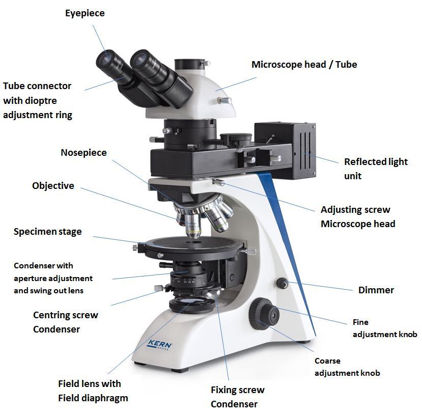
7 2 Nomenclature OPM-1_OPN-1_OPO-1-BA-e
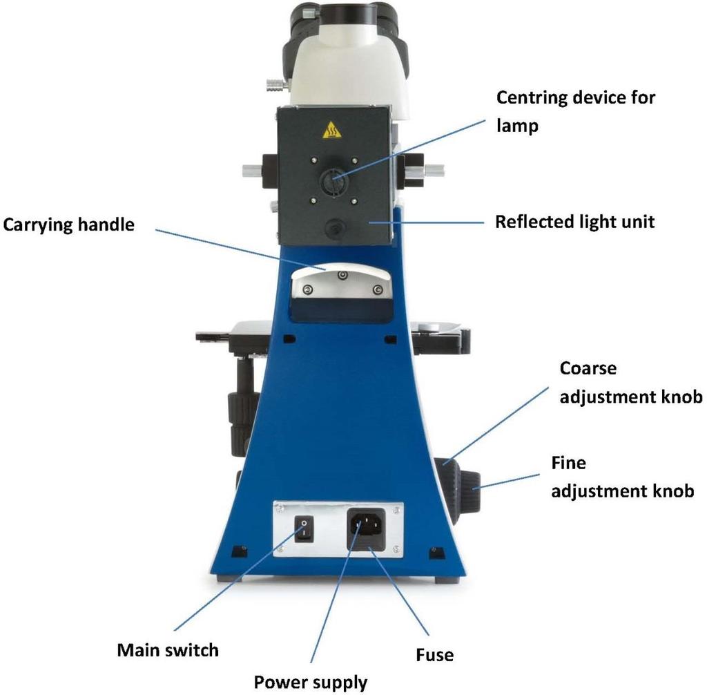
8 Rear view 7 OPM-1_OPN-1_OPO-1-BA-e-1510


9 Analyser unit / Reflected light unit OPM-1_OPN-1_OPO-1-BA-e

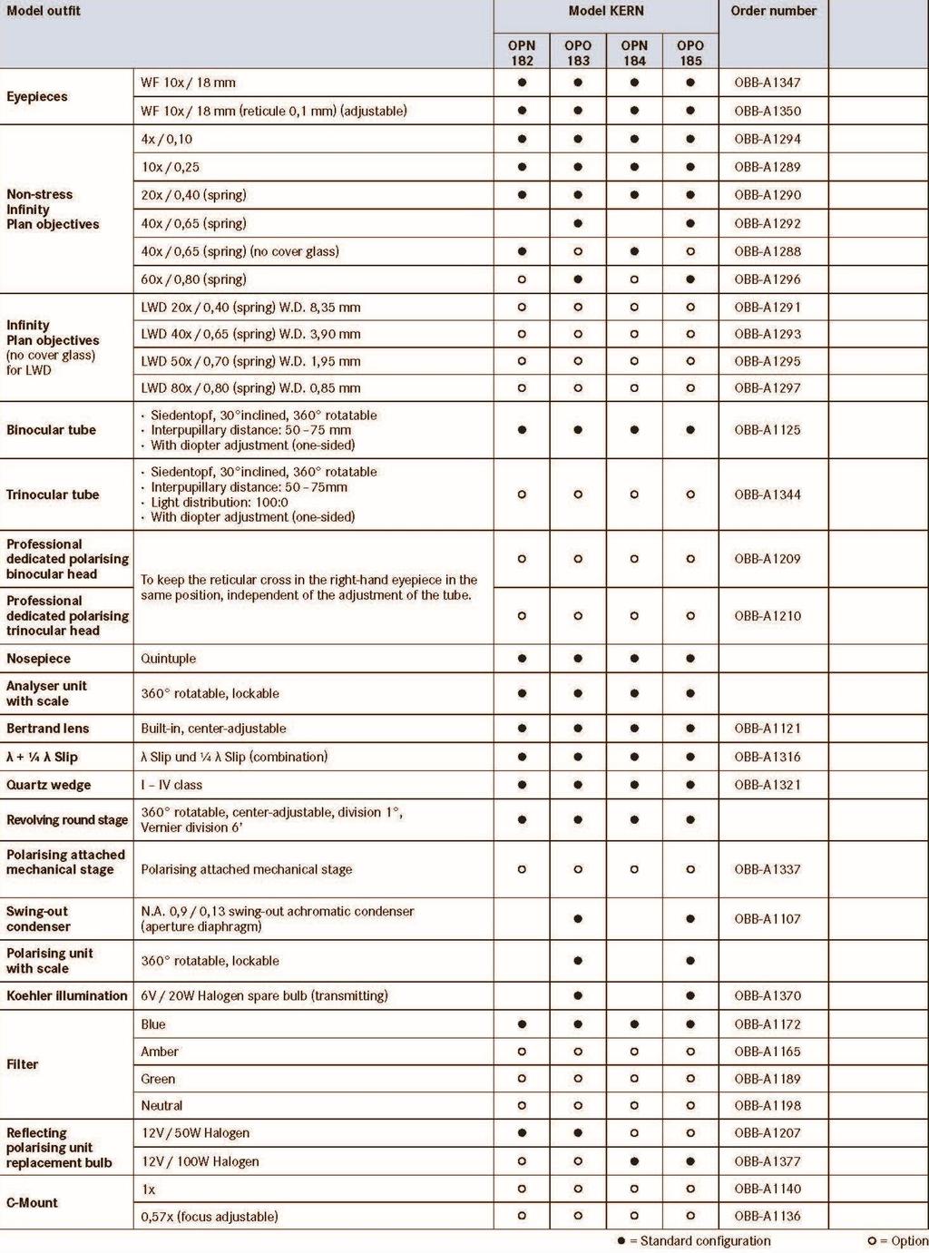
10 3 Technical data / Features Eyepieces: WF 10x / Ø 18 mm Objectives: OPM 181, OPN 182, OPN 184 Objectives: OPO 183, OPO 185 Non-stress 4x / 10x / 20x / 40x Non-stress 4x / 10x / 20x / 40x / 60x Product dimension: Net weight: 500x200x500 mm 14,5 kg Input voltage: Output voltage: Fuse: AC V, 50-60Hz DC 1,2-6V 2A 5x20mm 9 OPM-1_OPN-1_OPO-1-BA-e-1510

11 OPM-1_OPN-1_OPO-1-BA-e
12 11 OPM-1_OPN-1_OPO-1-BA-e-1510
13 4 Assembly OPM-1_OPN-1_OPO-1-BA-e
14 4.1 Analyser unit (+ reflected light unit) For devices without reflected light unit (OPM-1) it is only needed to mount the analyser unit. For devices, which are equipped with a reflected light unit (OPN-1, OPO-1), the analyser unit and the main part of the reflected light unit are already firmly connected. At this you firstly have to unite the lamp housing and the reflected light unit on their connection points. After that the connection has to be fixated by an Allen screw, which is attached to the right-hand side of the connection point of the lamp housing. Now the slides for analyser, polariser and colour filter can be attached to the appropriate slots (see page 8). Afterwards in order to install the reflected light unit to the microscope, you must loosen the fixing screw on the tube connection point and remove the black protective cover. You can then insert the round dovetail bracket on the light unit into the round dovetail bracket on the housing and fix it with the fixing screw. When doing this, you should always make sure that you do not touch the lenses with your bare fingers and that no dust enters the apertures. Finally you must establish the electrical connection between power supply unit and reflected light unit. The plug of the connection cable, attached to the rear of the light unit has to be installed to the socket on the rear of the power supply unit. Please do also use the screw lock on the plug. 4.2 Microscope head First you must loosen the fixing screw on the tube connection point of the reflected light unit / analyser unit and remove the black protective cover. You can then insert the round dovetail bracket on the head into the round dovetail bracket on the reflected light unit and fix it with the fixing screw. When doing this, you should always make sure that you do not touch the lenses with your bare fingers and that no dust enters the apertures. 4.3 Objectives The specimen stage must be in its lowest position so that the objectives can be screwed into the nosepiece. You can then screw the objectives into the nosepiece so that when you turn the nosepiece in a clockwise direction, the objective with the next strongest magnification appears. You must make sure that you do not touch the lenses with your bare fingers and that no dust enters the apertures. 13 OPM-1_OPN-1_OPO-1-BA-e-1510
15 4.4 Eyepieces You must always use eyepieces with the same magnification for both eyes. These are simply placed onto the tube connectors, once you have first removed the plastic protective caps. There is no way of fixing them. You should always make sure that you do not touch the lenses with your bare fingers and that no dust enters the apertures. 4.5 Condenser (Swing out) / Transmitting light polariser OPM-1, OPO-1 We recommend that you use the course adjustment knob to bring the specimen stage to its uppermost position. Use the focus dial of the condenser to move the condenser holder to the central position. In this way the condenser can be fitted at the right place in the condenser holder and fixed with the adjusting screw. When doing this, you should be able to read the scale from the front. You should avoid touching the optical lenses with bare fingers. There is a transmitting light polariser (incl. scale) located on the bottom side of the condenser. It is fastened with an Allen screw on the side of the condenser. When loosening this screw the polariser can be turned in both directions. For point 6 (Camera connection), please see Chapter 8 Use of optional accessories. 5 Operation 5.1 Getting started The very first step is to establish a power connection using the mains plug. You should first adjust the dimmer to a low level, so that when you look through the eyepiece for the first time, your eyes are not immediately subject to a high level of light. You can now switch on the lighting using the main switch. The next step is to place a slide with the sample on the round table. The object must be prepared accordingly in order to be suitable for applications with polarised transmitting or reflected light. With help of the object holder you can fix the specimen slide to the table. The object can be only observed if it is located inside of the beam path. OPM-1_OPN-1_OPO-1-BA-e
16 5.2 (Pre-) focussing When you are observing an object, you must have the correct distance to the objective to achieve a sharp image. In order to find this distance at the beginning (without other default settings of the microscope) place the objective with the lowest magnification in the beam path, look through the right eyepiece with the right eye and turn it slowly using the coarse adjustment knob (see illustration). The simplest way of doing this would be to first raise the specimen stage (using the coarse adjustment knob) until it is just under the objective and then lower it slowly. As soon as an image is recognisable (no matter how sharp), then you should only adjust the focus using the fine adjustment knob. Adjusting the torque of the coarse and fine adjustment knob Next to the left adjustment wheel for the coarse and fine adjustment knob there is a ring which you can use to alter the torque of these wheels. Turning it in a clockwise direction reduces the torque and turning it in an anti-clockwise direction increases it. On one hand, this function can help to make it easier to adjust the focus and on the other hand it can prevent the specimen stage from slipping down unintentionally. Important: In order to avoid damaging to the focussing system, the left and right adjustment wheels for the coarse and fine adjustment knob must never be rotated at the same time in opposite directions. 15 OPM-1_OPN-1_OPO-1-BA-e-1510

17 5.3 Adjusting the interpupillary distance With binocular viewing, the interpupillary distance must be adjusted accurately for each user, in order to achieve a clear image of the object. While you are looking through the eyepieces, use your hands to hold the righthand and lefthand tube housing firmly. By pulling them apart or pushing them together, you can either increase or reduce the interpupillary distance (see illustration). As soon as the field of views of the lefthand and righthand eyepieces completely overlap each other, i.e. they combine to form a circular image, then the interpupillary distance is set correctly. 5.4 Dioptre adjustment The eye strengths of each eye of the microscope user can often be slightly different, which in daily life has no consequences. But when using a microscope this can cause problems in achieving precise focussing. You can use a mechanism on both tube connectors (dioptre adjustment rings) to compensate for this as follows. 1. Put the right dioptre adjustment ring to position Look through the right eyepiece with the right eye and bring the object into focus by using the coarse and fine adjustment knob. 3. Then look through the left eyepiece with the left eye and use the lefthand dioptre adjustment ring to focus the image. To do this, you just need to turn the ring in both directions (see illustration), to find out where the image is at its most focussed. OPM-1_OPN-1_OPO-1-BA-e

18 5.5 Centre-adjusting the stage In order to analyse certain objects with help of the polarization method, it is important to be able to revolve the table. Thus, the contrasting of the object can be observed depending on its angle position between polariser and analyser. For getting ideal results the centre of the rotation axis of the table must be aligned to the centre of the optical beam path. The microscopes of the OPM-1, OPN-1 and OPO-1 series are correctly set at factory. However we recommend to regularly check before the first use and every now and then if the table is centre-adjusted. In case of a decentration the following steps have to be carried out. 17 OPM-1_OPN-1_OPO-1-BA-e-1510
19 1. Bring the 10x objective into beam path. 2. Assure, that one eyepiece with scale is attached to (one of) the tube connector(s). 3. Locate an appropriate specimen slide onto the table. This slide should preferably be equipped with a micro reticule. It would be also possible to use an object which includes plenty of single dots and for which one of those dots has such a size, so that it aligns with the centre cross point of the scale, visible inside of the eyepiece(s). 4. Locate the specimen slide to that point, that, when observing through the eyepiece(s), the centre of the reticule is on the centre of the eyepiece scale. 5. Assure, that the fixing screw of the table is loosened, in order to be able to revolve the table. If the table is not or heavy to revolve, even though the fixing screw is loosened, this serves as an evidence for a significant decentration of the table. 6. If the table is perfectly centre-adjusted, you will note that, during a complete rotation of the table, both centres stay always aligned to each other. In this case, the procedure would be finished at that point. 7. If the table is not centre-adjusted, you will note that the centre of the reticule moves, directly after the beginning of the rotation of the table, away from the centre of the eyepiece scale. And it matches again only after the complete rotation. 8. Estimate the centre of the circular motion, which the reticule is doing, and move the specimen slide, so that the centre of the reticule matches this estimated centre. 9. Operate the centring screws, so that the centre of the reticule and the centre of the eyepiece scale are aligning to each other again. 10. Repeat steps 6-9. OPM-1_OPN-1_OPO-1-BA-e
, you can then adjust the overall magnification using the nosepiece, as necessary. By turning the nosepiece you can bring any one of the four other objectives into the beam path.")
20 5.6 Adjusting the magnification After prefocussing has been carried out using the objective with the lowest magnification (see section 5.2), you can then adjust the overall magnification using the nosepiece, as necessary. By turning the nosepiece you can bring any one of the four other objectives into the beam path. When adjusting the nosepiece, you must take the following points into account: - The required objective must be properly locked in place at all times. - The nosepiece should not be rotated by holding individual objectives, you should use the silver ring above the objectives (see illustration). - When rotating the nosepiece you must always make sure that the objective which is about to be positioned in the beam path does not touch the object holder. This can lead to significant damage to the objective lens. We recommend that you always check from the side to make sure that there is sufficient leeway. If this should not be the case, the specimen stage must be lowered accordingly. If you have focussed the object to be observed for a specific magnification, then if you select the objective with the next greatest magnification, then the object will be slightly out of focus. Use the fine adjustment knob to make a slight adjustment and restore the focus. 19 OPM-1_OPN-1_OPO-1-BA-e-1510


21 5.7 Using eye cups The eye cups supplied with the microscope can basically be used at all times, as they screen out intrusive light, which is reflected from light sources from the environment onto the eyepiece, and the result is better image quality. But primarily, if eyepieces with a high eye point (particularly suitable for those who wear glasses) are used, then it may also be useful for users who don t wear glasses, to fit the eye cups to the eyepieces. These special eyepieces are also called High Eye Point eyepieces. They can be identified by the glasses symbol on the side. They are also marked in the item description by an additional H (example: HSWF 10x Ø 23 mm). When fitting the eye cups, make sure that the dioptre setting is not moved. We would therefore advise that you hold the dioptre compensation ring on an eyepiece with one hand while you fit the eye cup with the other. Before using the microscope, users who wear glasses must remove the eye cups, which you may find on High Eye Point eyepieces. As the eye cups are made of rubber, you must be aware that when you are using them, they can become slightly dirty through grease residues. In order to maintain hygiene, we would therefore recommend that you clean the eye cups regularly (e.g. with a damp cloth). Eye cups High Eye Point eyepiece (identified by the glasses symbol) OPM-1_OPN-1_OPO-1-BA-e
22 5.8 Adjusting the analyser unit In order to be able to apply the polarisation method, besides of the bright field method, certain components need to be adjusted. Basically, therefore the correct interaction between polariser and analyser is required. The analyser is located in one of the round apertures of a certain slide, the other aperture is empty (glass plate). This slide is additionally equipped with a rotary knob (incl. scale). If the analyser needs to be used, it has to be inserted into the appropriate slot (see page 8, top figure) and then pushed forward to the second snap-in position. After the usage the analyser can be pulled out to the first snap-in position, in order to bring it out of the beam path. The analyser unit is the counter part for both the transmitting light polariser and the reflected light polariser. The transmitting light polariser is located on the bottom side of the transmitting light condenser, it can be rotated if needed. The reflected light polariser is located in one the slides for the reflected light unit (see section 5.10). The setting of the analyser now has to be done with help of the rotary knob, which needs to display 0. As a result, provided that the transmitting light polariser is set to 0 as well, the orthogonality between polariser and analyser, which is required for common polarisation applications, is ensured. An indication for this orthogonality is the maximum obscuration, which can be thereby observed in the field of view. The slide of the Bertrand lens needs to be in the pulled out position for standard polarisation processes. It can be moved into the beam path in order to observe the interference pattern of a sample in regards to conoscopic analysis. If needed, you can use the Lambda filters, which are parts of the standard equipment. Therefore you need to insert the according slide into the appropriate slot. (Previously remove one of the retaining screws and reattach it after the insertion again). This slide contains three apertures, which can be brought in each case into the beam path with help of a snap-in function. The middle aperture does not contain any filter, at this position you can apply the standard polarising method. Each of the two other apertures contains one Lambda filter (¼ λ and λ). They can be used in order to adjust the interference colours, which are the result of polarised light colliding with the sample. 21 OPM-1_OPN-1_OPO-1-BA-e-1510

23 5.9 Adjusting the Koehler illumination for transmitted light OPM-1, OPO-1 To make sure that perfect image results are achieved during microscopic observation, it is important that the direction of light of the microscope is optimised. If, as with the devices in the KERN OPM-1 and OPO-1 series, the lighting can be set in accordance with Koehler, the result is homogenous illumination of the slide and avoidance of disruptive stray light. The necessary control elements for this are: Height-adjustable and centre-adjustable condenser with aperture diaphragm Field diaphragm When adjusting the Koehler lighting for the first time, you must first select the lowest possible objective magnification, so that you can carry out the following steps. 1. Use the condenser focus wheel to position the condenser directly below the specimen stage. Switch on the lighting and use the coarse and fine adjustment knob to bring the slide with the cover glass positioned facing upwards into focus. 2. Close the field diaphragm completely using its adjusting ring. When you look in the microscope a blurred image appears in the aperture. If the microscopic image is completely dark, the image for the field diaphragm is outside the field of view and must be brought into the field of view using the centring screws on the condenser. OPM-1_OPN-1_OPO-1-BA-e

24 3. Adjust the height of the condenser until the image from the field diaphragm appears clearly in the field of view. For some microscopes there is a risk that you will lift the condenser up so high that it collides with the object holder. Therefore care is needed when doing this. 4. Use the centring screws of the condenser holder to bring the image from the field diaphragm into the centre of the field of view. 5. Open the field diaphragm until it just disappears out of the field of view. If necessary, simply re-centre using the centring screws on the condenser holder. 23 OPM-1_OPN-1_OPO-1-BA-e-1510

25 6. Use the aperture diaphragm of the condenser to find the very best compromise between contrast and resolution for the microscopic image. The scale divisions on the condenser can be used as a guideline. Select in accordance with the objective being used. The view in the tube without the eyepiece should look something like the illustration on the right. The diameter of the aperture diaphragm which is then visible should make up approximately 2/3 of the pupil diameter. If the eyepiece should be removed, for checking, then please make sure that no dirt or dust falls into the tube. 7. It is possible to alter the brightness of the bulb using the dimmer. The brightness is always controlled by the bulb brightness and not by the aperture diaphragm. 8. Possibly there is the need of re-adjusting the focus and x-y axis. 9. Observe the object. If another magnification is selected afterwards, then the Koehler illumination does not have to be reset from scratch, only the aperture diaphragm and field diaphragm need to be adjusted as required. As a result you can always check whether the condenser needs to be re-centred. OPM-1_OPN-1_OPO-1-BA-e
26 5.10 Adjusting the illumination for incident light OPN-1, OPO-1 Just like the components of the transmitted illumination those ones of the incident illumination can be adjusted according to the application requirements as well. The following components are provided on this occasion: Field diaphragm and aperture diaphragm Both of the diaphragms have the same functions like described for the adjustment of the transmitted light (see section 5.9). To open and close these diaphragms you have to operate the levers located at the top of the reflected light unit. Colour filter The colour filter slide has two round apertures. One of them is with an integrated blue filter, the other one is empty. This slide is marked with the number 2 and therefore it has to be attached to the slot marked with the number 2 as well. If necessary, one of the two apertures has to be snapped into the beam path. Polariser The polariser slide has two round apertures. One of them is with an integrated polariser, the other one is empty. This slide is marked with the number 1 and therefore it has to be attached to the slot marked with the number 1 as well. If necessary, one of the two apertures has to be snapped into the beam path. Diffuser Directly behind the aperture diaphragm there is a slot for the diffuser. It is integrated in a round aperture of a little black slide. That slide can be attached in order to equally disperse the light of the halogen lamp. 25 OPM-1_OPN-1_OPO-1-BA-e-1510
27 Centring of the lamp When using the reflected light unit for a long time, the lamp holder possibly moves out of its centre due to the heat development. In this case the illumination is no longer efficiently adjusted. This circumstance can be identified by the user when the background brightness of the field of view has an uneven distribution. This malposition can be corrected by performing the following method. 1. Make sure, that the lamp housing has cooled down. 2. Switch on the reflected light unit. 3. Choose the objective with the lowest magnification for the beam path. 4. Remove all the (filter) slides from the beam path. 5. If there is one, remove the object (slide) from the stage. 6. Remove one of the eyepieces from the tube. 7. While watching through the tube connector, close the aperture diaphragm of the reflected light unit, so that its border can be seen clearly. 8. The decentred image of the lamp filament can now be seen as well. 9. Loosen the rotary knob on the rear of the lamp housing, so that you can move it together with the attached lamp holder. 10. Look through the tube connector and move the rotary knob in order to bring the image of the lamp filament back to the centre of the opening of the aperture diaphragm. 11. Fixate the rotary knob again. OPM-1_OPN-1_OPO-1-BA-e
28 6 Changing the bulb 6.1 Transmitted light OPM-1, OPO-1 You must not attempt to change the bulb immediately after the microscope has been used, as the bulb will still be hot and so there is a risk that the user could be burnt. Before changing the bulb the device must be switched off and unplugged. To change the bulb, tip the device carefully to the back or side. When doing this, please make sure that all microscope components are firmly fixed. The bulb holder is on the underside of the device. It can be opened by undoing the screws on the holder (see illustration). We recommend that here you should also test again, to check that heat is no longer being produced. The defective bulb can be pulled out of the socket and be replaced with a new one. After the bulb holder has been replaced in the underside of the device and the screws replaced, the bulb replacement procedure is complete. Important: When fitting the new bulb into the socket, it must only be handled with sterile gloves or using the bulb packaging film. Grease and dust residue can have a negative effect on the light quality and service life. 27 OPM-1_OPN-1_OPO-1-BA-e-1510
29 6.2 Reflected light OPN-1, OPO-1 You must not attempt to change the bulb immediately after the microscope has been used, as the bulb will still be hot and so there is a risk that the user could be burnt. Before changing the bulb the device must be switched off and unplugged. All 8 screws on the rear edges of the lamp housing have to be removed. Thus the holder of the halogen lamp can be separated from the rest of the housing. The defective bulb can be pulled out of the socket and be replaced with a new one. Finally the lamp housing is screwed together again. 7 Changing the fuse 7.1 Transmitted light OPM-1, OPO-1 The fuse housing is on the rear of the microscope below the mains power supply socket. With the device switched off and unplugged, you can pull out the housing. When doing this, it is helpful to use a screwdriver or similar tool. The defective fuse can be removed from its housing and be replaced with a new one. After that, you just need to insert the fuse housing back into the insertion point below the mains power supply socket. 7.2 Reflected light OPN-1, OPO-1 The fuse housing is on the rear of the power supply unit of the reflected light unit. With the device switched off and unplugged, you can pull out the housing. The defective fuse can be removed from its housing and be replaced with a new one. After that, you just need to insert the fuse housing back into the insertion point below the mains power supply socket. OPM-1_OPN-1_OPO-1-BA-e
30 8 Using optional accessories 8.1 Camera connection (only for trinocular version) Due to the trinocular tube, which can be optionally fitted for the OPM-1, OPN-1 and OPO-1 series, it is possible to connect microscope cameras to the device, in order to digitally record images or sequences of images of an object being observed. After the plastic cover has been removed from the camera adapter connector on the top of the microscope head, then a suitable adapter must be fitted. In general there are two C-mount adapters available for this (1x and 0.57x magnification, see Chapter 3 Features). After fitting one of these adapters it can be fixed with the fixing screw. A camera which has a C-mount thread is then screwed on top of the adapter. We recommend that you first adjust the field of view using the eyepieces on the device for the existing requirements, and then carry out the observation using the microscope camera (i.e. using the PC screen which is connected). To do this, the trinocular toggle rod on the righthand side of the microscope head must be pulled out. The light from the microscope lighting is deflected so that it is completely in the beam path for the camera, which causes a dark field of view in the eyepieces. This means that it is not possible to simultaneously observe by the eyepieces and PC screen. For C-mount adapters, which have their own integrated magnification, the image which is shown on the camera connected to the device can often have a different level of focus compared with the image on the eyepiece. In order to be able to bring both images into focus, the focus can be adjusted by those adapters. 29 OPM-1_OPN-1_OPO-1-BA-e-1510
31 9 Trouble shooting Problem Possible causes The mains plug is not correctly plugged in The bulb does not light There is no power at the socket Defective bulb Defective fuse The bulb blows immediately The field of view is dark You cannot adjust the brightness The field of view is dark or is not correctly illuminated The field of view of one eye does not match that of the other eye The specified bulb or fuse has not been used The aperture diaphragm and/or field diaphragm are not opened wide enough The selector switch for the beam path is set to Camera The condenser is not correctly centred The brightness control has been set incorrectly The condenser has not been correctly centred The condenser is too low The objective is not positioned correctly on the beam path The selector switch for the beam path is between two settings The nosepiece is not correctly fitted The condenser is not correctly fitted An objective is being used which doesn t match the lighting area of the condenser The condenser has not been correctly centred The field diaphragm is closed too tightly The bulb is not correctly fitted The interpupillary distance is not correctly adjusted Dioptre setting has not been carried out correctly Different eyepieces are used for the righthand and lefthand side The eyes are not used to using a microscope OPM-1_OPN-1_OPO-1-BA-e
32 Problem Blurred details Bad image Bad contrast Vignetted field of view Possible causes The aperture diaphragm is not opened wide enough The condenser is too low The objective does not belong to this microscope The front lens of the objective is dirty An immersion object has been used without immersion oil The immersion oil contains air bubbles The condenser is not correctly centred The recommended immersion oil has not been used Dirt / dust on the objective Dirt /dust on the front lens of the condenser Dirt / dust on the eyepieces Dirt or dust in the field of view Dirt / dust on the front lens of the condenser Dirt / dust on the object One side of the image is blurred The stage was not correctly fitted The objective is not positioned correctly on the beam path The nosepiece is not correctly fitted The upper side of the object is facing down The image flickers The coarse adjustment knob is difficult to turn The stage moves down on its own The fine adjustment knob moves on its own When you move the table, the image becomes blurred The nosepiece is not correctly fitted The objective is not positioned correctly on the beam path The condenser has not been correctly centred The rotational resistance brake is too tight The table is blocked by a solid body The rotational resistance brake is not tight enough The stage was not correctly fitted 31 OPM-1_OPN-1_OPO-1-BA-e-1510

33 10 Service If, after studying the user manual, you still have questions about commissioning or using the microscope, or if unforeseen problems should arise, please get in touch with your dealer. The device may only be opened by trained service engineers who have been authorised by KERN. 11 Disposal The packaging is made of environmentally-friendly materials, which you can dispose of at your local recycling centre. Disposal of the storage box and device must be carried out by the operator in accordance with all national or regional laws in force in the location of use. 12 Further information The illustrations may differ slightly from the product. The descriptions and illustrations in this user manual are subject to change without notice. Further developments on the device may lead to these changes. All language versions contain a non-binding translation. The original German document is the binding version. OPM-1_OPN-1_OPO-1-BA-e
User instructions Metallurgical inverted microscope
 KERN & Sohn GmbH Ziegelei 1 D-72336 Balingen E-mail: info@kern-sohn.com Tel: +49-[0]7433-9933-0 Fax: +49-[0]7433-9933-149 Internet: www.kern-sohn.com User instructions Metallurgical inverted microscope
User instructions Metallurgical microscope
 KERN & Sohn GmbH Ziegelei 1 D-72336 Balingen E-Mail: info@kern-sohn.com User instructions Metallurgical microscope Tel: +49-[0]7433-9933-0 Fax: +49-[0]7433-9933-149 Internet: www.kern-sohn.com KERN OKM-1
User instructions Compound laboratory microscope
 KERN & Sohn GmbH Ziegelei 1 D-72336 Balingen E-mail: info@kern-sohn.com User instructions Compound laboratory microscope Tel: +49-[0]7433-9933-0 Fax: +49-[0]7433-9933-149 Internet: www.kern-sohn.com KERN
User instructions Compound laboratory microscope
 KERN & Sohn GmbH Ziegelei 1 D-72336 Balingen E-mail: info@kern-sohn.com User instructions Compound laboratory microscope Tel: +49-[0]7433-9933-0 Fax: +49-[0]7433-9933-149 Internet: www.kern-sohn.com KERN
User instructions Transmitted light phase contrast microscope
 KERN & Sohn GmbH Ziegelei 1 D-72336 Balingen E-Mail: info@kern-sohn.com Tel: +49-[0]7433-9933-0 Fax: +49-[0]7433-9933-149 Internet: www.kern-sohn.com User instructions Transmitted light phase contrast
User instructions Transmitted light laboratory microscope
 KERN & Sohn GmbH Ziegelei 1 D-72336 Balingen E-Mail: info@kern-sohn.com Tel: +49-[0]7433-9933-0 Fax: +49-[0]7433-9933-149 Internet: www.kern-sohn.com User instructions Transmitted light laboratory microscope
User instructions Transmitted light laboratory microscope (digital)
") KERN & Sohn GmbH Ziegelei 1 D-72336 Balingen E-Mail: info@kern-sohn.com Tel: +49-[0]7433-9933-0 Fax: +49-[0]7433-9933-149 Internet: www.kern-sohn.com User instructions Transmitted light laboratory microscope
KERN & Sohn GmbH Ziegelei 1 D-72336 Balingen E-Mail: info@kern-sohn.com Tel: +49-[0]7433-9933-0 Fax: +49-[0]7433-9933-149 Internet: www.kern-sohn.com User instructions Transmitted light laboratory microscope
User instructions Biological inverted microscope
 KERN & Sohn GmbH Ziegelei 1 D-72336 Balingen E-mail: info@kern-sohn.com User instructions Biological inverted microscope Tel: +49-[0]7433-9933-0 Fax: +49-[0]7433-9933-149 Internet: www.kern-sohn.com KERN
Therefore, all descriptions and illustrations in this instruction manual, including all specifications are subject to change without notice.
 We are constantly endeavouring to improve our instruments and to adapt them to the requirements of modern research techniques and testing methods. This involves modification to the mechanical structure
TABLE OF CONTENTS. Safety notes i. Care and Maintenance. ii. 1. Components Illustration Installation of Components.. 4
 TABLE OF CONTENTS Safety notes i Care and Maintenance. ii 1. Components Illustration... 1 2. Installation of Components.. 4 2.1 Installation Diagram... 4 2.2 Installation Procedures 5 3. Operation...11
User Manual. Trinocular Metallurgical Microscope. MicroscopeNet.com
 User Manual Trinocular Metallurgical Microscope Model M83MPTR MicroscopeNet.com Table of Contents i. Caution.. 1 ii. Care and Maintenance... 2 1. Components Illustration..... 3 2. Installation...4 3. Operation
User Manual. Digital Compound Binocular LED Microscope. MicroscopeNet.com
 User Manual Digital Compound Binocular LED Microscope Model MD82ES10 MicroscopeNet.com Table of Contents i. Caution... 1 ii. Care and Maintenance... 2 1. Components Illustration... 3 2. Installation...
Zoom Stereo Microscope NYMCS-360 Instruction Manual
 Zoom Stereo Microscope NYMCS-60 Instruction Manual This manual is written for stereo microscope NYMCS-60. To ensure the safety, obtain optimum performance and to familiarize yourself fully with the use
ML7520 ML7530 DIOPTER ADJUSTMENT RING BINOCULAR BODY, INCLINED 30. (a) Field Iris Control Lever. (c) Filter Slots EYEPIECES, KHW10X
 Field Iris Control Lever. (c) Filter Slots EYEPIECES, KHW10X") JAPAN DIOPTER ADJUSTMENT RING BINOCULAR BODY, INCLINED 30 (a) Field Iris Control Lever (c) Filter Slots EYEPIECES, KHW10X ANALYZER CONTROL LEVER (b) Aperture Iris Control Lever LIGHT SOURCE HOUSING VERTICAL
JAPAN DIOPTER ADJUSTMENT RING BINOCULAR BODY, INCLINED 30 (a) Field Iris Control Lever (c) Filter Slots EYEPIECES, KHW10X ANALYZER CONTROL LEVER (b) Aperture Iris Control Lever LIGHT SOURCE HOUSING VERTICAL
User Manual. Trinocular Infinity Compound LED Microscope. MicroscopeNet.com
 User Manual Trinocular Infinity Compound LED Microscope Model M8333Z series MicroscopeNet.com Table of Contents i. Caution... 1 ii. Care and Maintenance... 2 1. Components Illustration... 3 2. Installation...
OMM300. Inverted Metallurgical Microscope
 OMM300 Inverted Metallurgical Microscope Instruction Manual Please read the instructions carefully before operating CONTENTS Safety 2 Parts List 2 Features 3 Assembly 5 Operation 7 Maintenance 9 Specifications
Eyepieces KHW10X. Diopter Adjustment Ring. Binocular Body Inclined 30. Binocular Clamp Screw. Analyzer control Lever. Reflected Light Illuminator
 JAPAN Eyepieces KHW10X Diopter Adjustment Ring Binocular Body Inclined 30 Binocular Clamp Screw Analyzer control Lever Reflected Light Illuminator Ball-Bearing Objective Nosepiece Objectives Large Scan
Manual for BMS E1 eplan series, compound microscope
 Manual for BMS E1 eplan series, compound microscope The compound microscope allows it to study, at cell level, structures of textures of botanical and zoological nature. (e.g. slides of roots, leaves and
TEKSCOPE MICROSCOPE. Models N2 Series USER S MANUAL
 TEKSCOPE MICROSCOPE Models N2 Series USER S MANUAL Contents Before use 1 1.Nomenclature. 2 2.Operation 4 2-1 Angle of observation.. 4 2-2 Set the specimen slide.. 4 2-3 Set illumination 4 2-4 Adjust focus
STEINDORFF NYMC Polarizing Microscope
 NYMC38000 Polarizing Microscope In order to exert performance of this microscope and to ensure the safety, please read the operating instruction carefully before use. 1 I. APPLICATION: NYMC38000 series
Therefore, all descriptions and illustrations in this instruction manual, including all specifications are subject to change without notice.
 We are constantly endeavouring to improve our instruments and to adapt them to the requirements of modern research techniques and testing methods. This involves modification to the mechanical structure
Biological Microscope Manual
 Version No.: V1.2 Series Biological Microscope Manual This manual expatiates the using method, troubleshooting and maintenance about MT-50 series biological microscope. Please study this manual thoroughly
OM FL400. Reflected Light Fluorescence Microscope. Instruction Manual. Please read instructions carefully before using microscope.
 OM FL400 Reflected Light Fluorescence Microscope Instruction Manual Please read instructions carefully before using microscope. Contents Safety ---------------------------------------------- 2 Parts List
STEINDORFF METALLURGICAL MICROSCOPE. NYMCS-620 Instruction Manual
 METALLURGICAL MICROSCOPE NYMCS-620 Instruction Manual It is recommended strongly that you study this manual thoroughly before using the microscope. Retain this manual in an easily accessible place near
User Manual. Digital Compound Binocular LED Microscope. MicroscopeNet.com
 User Manual Digital Compound Binocular LED Microscope Model MD827S30L series MicroscopeNet.com Table of Contents i. Caution... 1 ii. Care and Maintenance... 2 1. Components Illustration... 3 2. Installation...
Artisan Technology Group is your source for quality new and certified-used/pre-owned equipment
 Artisan Technology Group is your source for quality new and certified-used/pre-owned equipment FAST SHIPPING AND DELIVERY TENS OF THOUSANDS OF IN-STOCK ITEMS EQUIPMENT DEMOS HUNDREDS OF MANUFACTURERS SUPPORTED
Components of the Microscope
 Swift M3 Microscope The Swift M3 is a versatile microscope designed for both microscopic (high magnification, small field of view) and macroscopic (low magnification, large field of view) applications.
Advanced Polarising Microscope Operating Instructions
 PriorLux POL Advanced Polarising Microscope Operating Instructions q~ääé=çñ=`çåíéåíë= 1. Introduction 2 2. Unpacking 2 3. Specifications 3 4. Component Parts 4 5. Electrical Connections & Safety 5 6.
Instruction Manual T Binocular Acromat Research Scope T Trinocular Acromat Research Scope
 Research Scope Instruction Manual T-29031 Binocular Acromat Research Scope T-29041 Trinocular Acromat Research Scope T-29032 Binocular Semi-Plan Research Scope T-29042 Trinocular Semi-Plan Research Scope
SWIFT SERIES M2252DGL MICROSCOPE
 SWIFT SERIES M2252DGL MICROSCOPE The M2252DGL Series is ideal for elementary to high school classrooms. Built to withstand student use, this series has locked-on eyepieces, objectives, illuminator housing
Biological Microscope
 Gima S.p.A. Via Marconi, 1-20060 Gessate (MI) Italy gima@gimaitaly.com - export@gimaitaly.com www.gimaitaly.com Biological Microscope USE AND MAINTENANCE BOOK ATTENTION: The operators must carefully read
Therefore, all descriptions and illustrations in this instruction manual, including all specifications are subject to change without notice.
 We are constantly endeavoring to improve our instruments and to adapt them to the requirements of modern research techniques and testing methods. This involves modification to the mechanical structure
Compound Microscopes Instruction Manual
 Compound Microscopes Instruction Manual Thank you for purchasing an Omano microscope. We hope you enjoy it! It has been checked for quality before shipping, but please take time to ensure that it has not
MANUAL MICROSCOPE SERIES. 73 Mall Drive, Commack, NY (P) (F)
 (F)") MANUAL 3002 MICROSCOPE SERIES 73 Mall Drive, Commack, NY 11725 631-864-1000 (P) 631-543-8900 (F) www.accu-scope.com info@accu-scope.com CONTENTS SAFETY NOTES... 3 CARE AND MAINTENANCE... 3 INTRODUCTION...
MANUAL 3002 MICROSCOPE SERIES 73 Mall Drive, Commack, NY 11725 631-864-1000 (P) 631-543-8900 (F) www.accu-scope.com info@accu-scope.com CONTENTS SAFETY NOTES... 3 CARE AND MAINTENANCE... 3 INTRODUCTION...
MANUAL EXC-350 MICROSCOPE SERIES
 MANUAL EXC-50 MICROSCOPE SERIES 7 Mall Drive, Commack, NY 75 6-864-000 (P) 6-54-8900 (F) www.accu-scope.com info@accu-scope.com CONTENTS SAFETY NOTES... CARE AND MAINTENANCE... INTRODUCTION... 4 UNPACKING
Swift M2252DGL Series Microscope Use and Care Manual
 Swift M2252DGL Series Microscope Use and Care Manual SWIFT OPTICAL Enduring Quality and Technical Excellence 1 Swift Series M2252DGL Microscope The M2252DGL Series is ideal for elementary to high school
Swift M2250 Series Microscope Care and Use Manual
 Swift M2250 Series Microscope Care and Use Manual SWIFT OPTICAL Enduring Quality and Technical Excellence. Swift Series M2250 Microscope The M2250 Series is ideal for elementary to high school classrooms.
Instruction Manual English Motic Incorporation Ltd.
 Instruction Manual English Motic Incorporation Ltd. UL Listed Product E250223 We are constantly endeavouring to improve our instruments and to adapt them to the requirements of modern research techniques
CALIBRATION OF MICROSCOPE EYEPIECE GRATICULE
 CALIBRATION OF MICROSCOPE EYEPIECE GRATICULE A typical eyepiece graticule looks like this: It is 10mm in length and each mm is divided into 10 parts So each small division = 0.1mm = 100µm The eyepiece
Laboratory Introduction
 Laboratory Introduction There are two basic categories of microscopes: light microscopes and electron microscopes. Light, or optical, microscopes require light waves to provide the illumination while electron
MANUAL EXC-400 MICROSCOPE SERIES. 73 Mall Drive, Commack, NY (P) (F)
 (F)") MANUAL EXC-400 MICROSCOPE SERIES 7 Mall Drive, Commack, NY 75 6-864-000 (P) 6-54-8900 (F) www.accu-scope.com info@accu-scope.com CONTENTS SAFETY NOTES... CARE AND MAINTENANCE... INTRODUCTION... 4 UNPACKING
MANUAL EXC-400 MICROSCOPE SERIES 7 Mall Drive, Commack, NY 75 6-864-000 (P) 6-54-8900 (F) www.accu-scope.com info@accu-scope.com CONTENTS SAFETY NOTES... CARE AND MAINTENANCE... INTRODUCTION... 4 UNPACKING
STEINDORFF Digital LCD Biological Microscope
 Digital LCD Biological Microscope -1260/ -1261 Instruction Manual Thanks for purchasing this digital LCD biological microscope. This user s manual is for item number -1260 & -1261. In order to operate
Polarizing Microscope BA310 POL. Instructions
 Polarizing Microscope BA310 POL Instructions 1 We are constantly endeavouring to improve our instruments and to adapt them to the requirements of modern research techniques and testing methods. This involves
OPERATING INSTRUCTIONS
 OPERATING INSTRUCTIONS Rotary Microtome CUT 4062 / CUT 5062 / CUT 6062 CUT 6062 illustrated above INS1000GB 2012-01-06 Instructions CUT4062 / CUT 5062 / CUT 6062 2 CONTENTS 1. INTENDED USE... 4 2. SYMBOLS...
Microlux IV COMPOUND MICROSCOPE USER S MANUAL
 Microlux IV COMPOUND MICROSCOPE USER S MANUAL This document is property of Seiler Instrument & Mfg. Co., Inc. No part of this manual should be reproduced or transmitted without the expressed written consent
Epi-LED FL Fluorescence Microscope Instruction Manual
 Epi-LED FL Fluorescence Microscope Instruction Manual Note If the equipment is used in a manner not specified by the manufacturer, the protection provided by the equipment may be impaired. WWW.MOTIC.COM
CLEANING FOR BETTER OBSERVATION AND PHOTOMICROGRAPHY
 CLEANING FOR BETTER OBSERVATION AND PHOTOMICROGRAPHY Microscope components get dirty with time. Dirt and dust particles on the optical components are especially damaging to image quality. When photographing
Microlux IV - LED COMPOUND MICROSCOPE USER S MANUAL
 Microlux IV - LED COMPOUND MICROSCOPE USER S MANUAL This document is property of Seiler Instrument & Mfg. Co., Inc. No part of this manual should be reproduced or transmitted without the expressed written
Quick Set Dovetail Jig
 Quick Set Dovetail Jig FOR HELP OR ADVISE ON THIS PRODUCT PLEASE CALL OUR CUSTOMER SERVICE HELP LINE : 01509 500359 THE MANUFACTURER RESERVES THE RIGHT TO ALTER THE DESIGN OR SPECIFICATION TO THIS PRODUCT
Swift M10 Series Microscope Use and Care Manual
 Swift M10 Series Microscope Use and Care Manual SWIFT OPTICAL Enduring Quality and Technical Excellence SWIFT M10 SERIES (Non-digital) Your Swift M10 microscope is an instrument of precision, both optically
S E L E C T I O N. Arm Curl. User manual
 S E L E C T I O N T H E S T R E N G T H E V O L U T I O N User manual The identification plate of the and manufacturer, affixed behind the seat, gives the following details: A Name and address of the manufacturer
A BRIEF INTRODUCTION TO MICROSCOPY The two key properties of a microscope that allow you to see microbes are resolution and magnification.
 A BRIEF INTRODUCTION TO MICROSCOPY The two key properties of a microscope that allow you to see microbes are resolution and magnification. Magnification refers to the enlargement of the specimen when seen
Microscopes. A guide to use, general Maintenance, and repair tailored to the Olympus CX-21 microscope
 Microscopes A guide to use, general Maintenance, and repair tailored to the Olympus CX-21 microscope Topics Principles of Operation Diagrams Applications History Safety Operation Preventive Maintenance
BA410E Series Biological Microscope Instruction Manual
 BA410E Series Biological Microscope Instruction Manual Note If the equipment is used in a manner not specified by the manufacturer, the protection provided by the equipment may be impaired. WWW.MOTIC.COM
Using the Nikon TE2000 Inverted Microscope
 Wellcome Trust Centre for Human Genetics Molecular Cytogenetics and Microscopy Core Using the Nikon TE2000 Inverted Microscope Fluorescence image acquisition using Scanalytic s IPLab software and the B&W
REPAIR INSTRUCTIONS. Cat. No Cat. No MILWAUKEE ELECTRIC TOOL CORPORATION. SDS Max Demolition Hammer. SDS Max Rotary Hammer
 Cat. No. 9-0 SDS Max Demolition Hammer Cat. No. -0 SDS Max Rotary Hammer MILWAUKEE ELECTRIC TOOL CORPORATION W. LISBON ROAD BROOKFIELD, WISCONSIN 00-0 8-9-0 d 000 8-9-0 d Special Tools Require Forcing
Basic Microscopy. OBJECTIVES After completing this exercise, you should be able to do the following:
 Page 1 of 10 Basic Microscopy OBJECTIVES After completing this exercise, you should be able to do the following: a. Name the parts of the compound microscope and the functions of each. b. Describe how
Nikon Ti-E Microscope Manual. Rightmire Hall Ohio State University. Director: Tony Brown Rightmire
 Nikon Ti-E Microscope Manual Rightmire Hall Ohio State University Director: Tony Brown Rightmire 060 292-1205 brown.2302@osu.edu Facility Manager: Paula Monsma Rightmire 062 293-0939 292-1367 monsma.1@osu.edu
Biology 29 Cell Structure and Function Spring, 2009 Springer LABORATORY 1: THE LIGHT MICROSCOPE
 Biology 29 Cell Structure and Function Spring, 2009 Springer LABORATORY 1: THE LIGHT MICROSCOPE Prior to lab: 1) Read these instructions (p 1-6) 2) Go through the online tutorial, the microscopy pre-lab
XSP-100XSP-100SM/ OF BIOLOGICAL MICROSCOPE OPERATION MANUAL READ THIS MANUAL BEFORE USING THE MICROSCOPE
 XSP-100XSP-100SM/ OF BIOLOGICAL MICROSCOPE OPERATION MANUAL READ THIS MANUAL BEFORE USING THE MICROSCOPE XSP-100XSP-100SM OF BIOLOGICAL MICROSCOPE OPERATION MANUAL Ⅰ.Application XSP-100/XSP-100SM of biological
ATD AMP Variable Speed Reciprocating Saw Owner s Manual
 ATD-10535 7 AMP Variable Speed Reciprocating Saw Owner s Manual Manufactured in China To ATD Tools, Inc. Specifications TECHNICAL SPECIFICATIONS Voltage: 120V Frequency: 60Hz Power input: 7 Amps No load
VARIABLE SPEED WOOD LATHE
 MODEL MC1100B VARIABLE SPEED WOOD LATHE INSTRUCTION MANUAL Please read and fully understand the instructions in this manual before operation. Keep this manual safe for future reference. Version: 2015.02.02
STEINDORFF NYMC C. Comparison Microscope. Operating Instructions. A. Features and Functions
 1 NYMC0035000C Comparison Microscope Operating Instructions A. Features and Functions Through optical enlargement, this comparison microscope, can help the user to observe clearly, by looking into the
Basics of Light Microscopy and Metallography
 ENGR45: Introduction to Materials Spring 2012 Laboratory 8 Basics of Light Microscopy and Metallography In this exercise you will: gain familiarity with the proper use of a research-grade light microscope
Therefore, all descriptions and illustrations in this instruction manual, including all specifications are subject to change without notice.
 We are constantly endeavouring to improve our instruments and to adapt them to the requirements of modern research techniques and testing methods. This involves modification to the mechanical structure
Allegro Home Office Assembly Instructions. Tipping Restraint. Bun Foot W/ Leveler. 4 pcs.
 email: info@riverside-furniture.com Allegro Home Office Assembly Instructions Components and Hardware List Page 1 of 5 Made in China Shelf Pin Wood Shelf File Rod & Clips 1/2"Wood Screw A 16 pcs. B 4 pcs.
Heiland electronic GmbH TD / TD1 / TD2. B&W-Densitometers. USERS MANUAL Version 5
 Heiland electronic GmbH TD / TD1 / TD2 B&W-Densitometers USERS MANUAL Version 5 2 Table of Contents 1. GENERAL INFORMATION...4 2. SAFETY REGULATIONS...5 3. AREA OF APPLICATIONS...5 4. INSTRUMENT DESCRIPTION...6
Swift M3600, M3700 Series Digital & Compound Microscope
 Swift M3600, M3700 Series Digital & Compound Microscope Use and Care Manual SWIFT OPTICAL Enduring Quality and Technical Excellence 2 Eyepiece Head Arm Nosepiece Objective Stage Iris Diaphragm Illuminator
STEINDORFF. Inverted Fluorescence Microscope NYMCS-702. Instruction Manual
 Inverted Fluorescence Microscope NYMCS-702 Instruction Manual This manual is written for Inverted Fluorescence Microscope NYMCS-702. For safety and for keeping the best performance, making you familiar
S E L E C T I O N. Upper Back. User manual
 and S E L E C T I O N T H E S T R E N G T H E V O L U T I O N User manual and and The identification plate of the and manufacturer, affixed to the frame on the side opposite the padded rest, gives the
MANUAL EXM-150 MICROSCOPE SERIES
 MANUAL EXM-150 MICROSCOPE SERIES 73 Mall Drive, Commack, NY 11725 631-864-1000 (P) 631-543-8900 (F) www.accu-scope.com info@accu-scope.com CONTENTS SAFETY NOTES... 3 CARE AND MAINTENANCE... 3 INTRODUCTION...
 GENERAL OPERATIONAL PRECAUTIONS WARNING! When using electric tools, basic safety precautions should always be followed to reduce the risk of fire, electric shock and personal injury, including the following.
Ⅰ. Application. Ⅱ. Main Technical Specification. AS1 Biological microscope,which is widely used in medical and
 Ⅰ. Application Objective Eyepiece Monocular Head The Light Above Coarse Adjustment Knob AS1 Biological microscope,which is widely used in medical and hygienic establishments for conventional microscopic
Model S-520 Coin Counter / Sorter Operating Manual
 Model S-520 Coin Counter / Sorter Operating Manual Table of Contents Using the Product Safely... 2 About the Warning Stickers and Points of Warning/... 2 Warning.... 3. 4 Names of the Main Parts......
MANUAL EXC-500 MICROSCOPE SERIES. 73 Mall Drive, Commack, NY (P) (F)
 (F)") MANUAL Revised v04308 EXC-500 MICROSCOPE SERIES 73 Mall Drive, Commack, NY 75 63-864-000 (P) 63-543-8900 (F) www.accu-scope.com info@accu-scope.com CONTENTS SAFETY NOTES... 3 CARE AND MAINTENANCE... 3
MANUAL Revised v04308 EXC-500 MICROSCOPE SERIES 73 Mall Drive, Commack, NY 75 63-864-000 (P) 63-543-8900 (F) www.accu-scope.com info@accu-scope.com CONTENTS SAFETY NOTES... 3 CARE AND MAINTENANCE... 3
Marine Invertebrate Zoology Microscope Introduction
 Marine Invertebrate Zoology Microscope Introduction Introduction A laboratory tool that has become almost synonymous with biology is the microscope. As an extension of your eyes, the microscope is one
LED PowerBlinder 4 ORDERCODE 41320
 LED PowerBlinder 4 ORDERCODE 41320 Congratulations! You have bought a great, innovative product from Showtec. The Showtec LED PowerBlinder brings excitement to any venue. Whether you want simple plug-&-play
ILFORD SPORTSVIEW PROJECTOR INSTRUCTION BOOK
 ILFORD SPORTSVIEW PROJECTOR INSTRUCTION BOOK Now that you're the owner of a new Sportsview Projector, you'll want to begin using it right away. The Sportsview Projector is extremely simple to operate,
Easy Kohler Illumination Method
 Easy Kohler Illumination Method ACADEMIC SKILLS CENTRE (ASC) A. Silverberg Completion of a Kohler illumination method is required before a microscope can be used efficiently. The Kohler method is designed
Ophthalmic Slit-lamp Microscope (SLM 1ER) Operation. Instruction
 Operation. Instruction") Ophthalmic Slit-lamp Microscope (SLM 1ER) Operation Instruction Content 1. Introduction... 2 1.1 Characteristics:... 2 1.2 Technical Parameters... 2 1.3 Notes:... 3 1.4 Caution:... 3 2. Installation...
Ophthalmic Slit-lamp Microscope (SLM 1ER) Operation Instruction Content 1. Introduction... 2 1.1 Characteristics:... 2 1.2 Technical Parameters... 2 1.3 Notes:... 3 1.4 Caution:... 3 2. Installation...
AGES 10+ INSTRUCTION MANUAL. 800x Power Advanced Microscope Biological Experiments Gear. x 2 NOT INCLUDED
 AGES 10+ INSTRUCTION MANUAL 800x Power Advanced Microscope Biological Experiments Gear x 2 NOT INCLUDED CONTENTS Microscope parts: 01 Eyepiece (Interchangeable 16x & 20x) 02 Focus Knob 03 Stage 04 Metal
3B SCIENTIFIC PHYSICS
 3B SCIENTIFIC PHYSICS Equipment Set for Modulus of Elasticity 1857 Instruction manual 5/16 TL/UD 1. Safety instructions Safe operation of this equipment is assured as long as it is used as stipulated.
ProHead. User s Guide
 ProHead User s Guide 2Profoto ProHead Profoto ProHead Thank you for choosing Profoto. Thanks for showing us your confidence by investing in a ProHead unit. For more than four decades we have sought the
CAPTURING IMAGES ON THE HIGH-MAGNIFICATION MICROSCOPE
 University of Virginia ITC Academic Computing Health Sciences CAPTURING IMAGES ON THE HIGH-MAGNIFICATION MICROSCOPE Introduction The Olympus BH-2 microscope in ACHS s microscope lab has objectives from
User guide ProHead Plus
 User guide ProHead Plus For other languages visit: /support ProHead Plus 2 Congratulations on your new Profoto product! Thanks for showing us your confidence by investing in a ProHead unit. For more than
Nuclear Associates
 Nuclear Associates 07-424 Digital Densitometer II Operators Manual March 2005 Manual No. 112111 Rev. 4 2003, 2005 Fluke Corporation, All rights reserved. Printed U.S.A. All product names are trademarks
AcuteB Head. User s Guide
 User s Guide SAFETY PRECAUTIONS! Read and follow all safety instructions below carefully to avoid injuries or damages! Make sure that this user manual always accompanies equipment! Profoto products are
English User's Guide
 User's Guide Imacon Flextight 646 2 2002 Imacon A/S. All rights reserved. Imacon Flextight 646 User's Guide, Part No 70030036, revision A. The information in this manual is furnished for informational
Using a Compound Light Microscope
 Name Class Date Laboratory Skills 5 Using a Compound Light Microscope Introduction Many objects are too small to be seen by the eye alone. They can be seen, however, with the use of an instrument that
ELECTRIC TOOL CORPORATION
 Cat. No. -0 / Hex Demolition Hammer Cat. No. 0-0 Spline Rotary Hammer MILWAUKEE ELECTRIC TOOL CORPORATION W. LISBON ROAD BROOKFIELD, WISCONSIN 00-0 -9-00 d 000 -9-00 d SpecialTools Require Forcing discs
S E L E C T I O N. Vertical Traction. User manual
 and S E L E C T I O N T H E S T R E N G T H E V O L U T I O N User manual and and The identification plate of the and manufacturer, affixed behind the backrest, gives the following details: A Name and
Part/Reorder Number: Version 1.0
 Part/Reorder Number: 870000 Version 1.0 Cross Match Technologies L SCAN 100/100R Operator s Manual Version 1.0 First Edition (August 2006) No portion of this guide may be reproduced in any form or by any
VARIABLE SPEED WOOD LATHE. Model DB900 INSTRUCTION MANUAL
 VARIABLE SPEED WOOD LATHE Model DB900 INSTRUCTION MANUAL 1007 TABLE OF CONTENTS SECTION...PAGE Technical data.. 1 General safety rules....1-3 Specific safety rules for wood lathe.....3 Electrical information.4
ProRing 2 User s Guide
 User s Guide Guide de Iútilisateur Benutzerhandbuch Manuale Utente Manual del usuario Gebruikershandleiding 用户说明书 Användarhandbok Brukerhåndbok Brugerhåndbog Käyyttöopas 2 Thank you for choosing Profoto.
Tapping Screw (W/Flange) 46 Cord Armor 47 Tube (D) 48 Cord. 45 Cord Clip. Tapping Screw (W/Flange) 10 Gear Cover Ass'y. 12 Socket (B) Ass'y
 46 Cord Armor 47 Tube (D) 48 Cord. 45 Cord Clip. Tapping Screw (W/Flange) 10 Gear Cover Ass'y. 12 Socket (B) Ass'y") W8VB The exploded assembly drawing should be used only for authoized service center. W8VB Item No. Part time 1 Magnetic Hex. Socket 2 Sub Stopper 3 O-Ring (S-16) 4 Locator (A) 5 Lock Sleeve (A) 6 O-Ring
W8VB The exploded assembly drawing should be used only for authoized service center. W8VB Item No. Part time 1 Magnetic Hex. Socket 2 Sub Stopper 3 O-Ring (S-16) 4 Locator (A) 5 Lock Sleeve (A) 6 O-Ring
SAFETY AND OPERATING MANUAL
 SAFETY AND OPERATING MANUAL BladeRunner X2 WX572 9 10 8 11 5 7 12 6 20 1 2 4 3 14 13 15 A2 A1 17 18 B2 B1 1 2 1 2 19 B3 3 4 2 C 1 D1 D1 C 2 1 E1 D2 1 2 E2 1 2 F G1 G1 F OFF ON G2 G3 H1 H2 I1 I2 I1 I2 J
FOLDING MACHINE PF-45A OPERATOR MANUAL 1. FUNCTION
 FOLDING MACHINE OPERATOR MANUAL 1. FUNCTION The folding machine is used to fold documents stand alone or in combination with a system 7. Sheets can be folded in various types. These are: single fold; letter
Motorized Axio Observer Start-up instructions
 Start-up instructions 1. If using fluorescence turn on Fluorescent light source. TL light Source (Hal 100) 2. Turn on microscope using switch on lower left side of the microscope. 3. If imaging, turn on
Power Planer 1900B/N1900B/1902
 Power Planer 1900B N1900B 1902 SPECIFICATIONS Model 1900B/N1900B/1902 Planing width... 82 mm Planing depth... 1 mm Shiplapping depth... 9 mm No load speed (min -1 )...16,000 Overall length... 290 mm Net
Microbiology Laboratory 2
 Microbiology Laboratory 2 Microscopy Background Microorganisms are too small to be seen with the naked eye. Thus a microscope is used to magnify objects so they can be observed. A lens consists of one